JP5950397B2 - Column-beam joint bracket - Google Patents
Column-beam joint bracket Download PDFInfo
- Publication number
- JP5950397B2 JP5950397B2 JP2012176089A JP2012176089A JP5950397B2 JP 5950397 B2 JP5950397 B2 JP 5950397B2 JP 2012176089 A JP2012176089 A JP 2012176089A JP 2012176089 A JP2012176089 A JP 2012176089A JP 5950397 B2 JP5950397 B2 JP 5950397B2
- Authority
- JP
- Japan
- Prior art keywords
- plate
- horizontal plate
- column
- steel beam
- fixing
- Prior art date
- Legal status (The legal status is an assumption and is not a legal conclusion. Google has not performed a legal analysis and makes no representation as to the accuracy of the status listed.)
- Active
Links
Images


Landscapes
- Joining Of Building Structures In Genera (AREA)
Description
本発明は、鋼管柱とH鋼梁との接合に用いる柱梁接合ブラケットに関する。 The present invention relates to a beam-column joining bracket used for joining a steel pipe column and an H steel beam.
従来、鋼管柱にH鋼梁を接合するには、まず、鋼管柱の外側面にH鋼梁と同一断面形状で短尺のブラケットを溶接しておく。次いで、このブラケットとH鋼梁の端面同士を付きあわせ、ブラケットの水平プレートとH鋼梁のフランジ間、及びブラケットの垂直プレートと梁のウェブ間に、それぞれ渡した固定板で両者をボルトにより連結する。 Conventionally, in order to join an H steel beam to a steel pipe column, first, a short bracket having the same cross-sectional shape as that of the H steel beam is welded to the outer surface of the steel pipe column. Next, the end faces of the bracket and H steel beam are put together, and both are connected by bolts with a fixed plate between the horizontal plate of the bracket and the flange of the H steel beam, and between the vertical plate of the bracket and the web of the beam. To do.
しかし、この方法では、クレーンなどで吊り込んだH鋼梁をブラケットと同一の高さに保持して端面同士を突き合わせる必要があり、不安定な状態で作業を行う必要がある。更に、ブラケットとH鋼梁の上下のフランジを固定するための固定板2枚と、ブラケットと梁のウェブを固定するための1枚の合計3枚の固定板が必要であることに加え、それに伴い固定するためのボルトが多数必要となる。 However, in this method, it is necessary to hold the H steel beam suspended by a crane or the like at the same height as the bracket, but the end surfaces face each other, and it is necessary to work in an unstable state. Furthermore, in addition to the need for two fixing plates for fixing the upper and lower flanges of the bracket and the H steel beam, and one fixing plate for fixing the bracket and beam web, Accordingly, a large number of bolts for fixing are required.
前記の問題を解決するために、H鋼梁の上下のフランジをスリット状に形成された水平プレート間に挿入して固定するブラケットが提案されている(例えば、特許文献1参照。)。
このブラケットは、1対の2枚の水平プレートを同方向に一体に突出させ、H鋼梁の上下のフランジ端部を、それぞれ各ダイヤフラムの水平プレートとフランジを貫通して差し込んだボルトで固定するものである。
このブラケットによれば、H鋼梁のフランジをブラケットの水平プレート間に挿入して、ボルトで直接連結するので、特別の固定板が不要であり、且つ、ボルトの本数も少なくてすむ。
In order to solve the above problem, a bracket has been proposed in which the upper and lower flanges of the H steel beam are inserted and fixed between horizontal plates formed in a slit shape (for example, refer to Patent Document 1).
In this bracket, a pair of two horizontal plates are integrally projected in the same direction, and the upper and lower flange ends of the H steel beam are fixed with bolts inserted through the horizontal plate and flange of each diaphragm, respectively. Is.
According to this bracket, since the flange of the H steel beam is inserted between the horizontal plates of the bracket and directly connected by bolts, a special fixing plate is not required and the number of bolts can be reduced.
しかし、特許文献1に記載のブラケットは、水平プレート2枚でスリットを形成する必要があり一対で4枚のプレートを必要とする。更に、上下の狭い間隔のスリットそれぞれに、H鋼梁の上下のフランジを挿入する作業が必要となる。
However, the bracket described in
本発明は、前記従来の問題を解決するものであり、部品点数が少なく、且つ、作業性に優れる柱梁接合ブラケットを提供することを目的としている。 The present invention solves the above-mentioned conventional problems, and an object thereof is to provide a column beam joint bracket having a small number of parts and excellent workability.
本発明は、以下の通りである。
1.鋼管柱の水平方向に突出形成された、上ダイヤフラムと下ダイヤフラムとからなる一対のダイヤフラムに、H鋼梁を固定する柱梁接合ブラケットであって、
一端側が前記上ダイヤフラムに接合し、他端側が前記H鋼梁の上フランジと上面を面一に突き合わせる上水平プレートと、
前記上水平プレートに対向し、一端側が前記下ダイヤフラムに接合し、他端側に前記H鋼梁の下フランジを載置固定する下水平プレートと、
前記上水平プレートと前記下水平プレートを接続し、前記H鋼梁のウェブを当接固定する垂直プレートと、
前記上水平プレートと前記上フランジとを連結固定する水平固定板と、を備え、
前記垂直プレートの下部には、前記下フランジを遊挿するための切欠き部が形成されており、
前記垂直プレートの前記ウェブとの当接部は、非当接部との間に段差を有することにより、該非当接部の表面と該ウェブの表面とが面一に形成され、前記垂直プレートと前記ウェブとを連結固定する垂直固定板を備えたことを特徴とする柱梁接合ブラケット。
2.前記上水平プレートの上面、前記下水平プレートの前記H鋼梁との当接面、前記垂直プレートの該H鋼梁との当接面、前記水平固定板の下面のうちの少なくとも一面には、滑り止め加工が施されている1.に記載の柱梁接合ブラケット。
3.前記垂直固定板の前記H鋼梁との当接面には、滑り止め加工が施されている1.又は2.に記載の柱梁接合ブラケット。
4.前記滑り止め加工が施された面は、多数の凹凸状のヤスリ目に形成されている2.又は3.に記載の柱梁接合ブラケット。
5.前記上フランジ及び前記上水平プレートの側端面同士及び、前記下フランジ及び前記下水平プレートの側端面同士は、いずれも面一となるように垂直プレートの位置決めをした1.乃至4.のうちのいずれか1項に記載の柱梁接合ブラケット。
The present invention is as follows.
1. A column beam joint bracket for fixing an H steel beam to a pair of diaphragms formed by projecting in the horizontal direction of a steel pipe column and comprising an upper diaphragm and a lower diaphragm,
An upper horizontal plate having one end joined to the upper diaphragm and the other end abutting the upper flange and the upper surface of the H steel beam flush with each other;
A lower horizontal plate facing the upper horizontal plate, one end side of which is joined to the lower diaphragm, and the lower flange of the H steel beam is mounted and fixed to the other end side;
A vertical plate connecting the upper horizontal plate and the lower horizontal plate and abutting and fixing the web of the H steel beam;
A horizontal fixing plate for connecting and fixing the upper horizontal plate and the upper flange;
At the bottom of the vertical plate, a notch for loosely inserting the lower flange is formed ,
The contact portion of the vertical plate with the web has a step between the non-contact portion and the surface of the non-contact portion and the surface of the web are formed flush with each other. A column beam joint bracket comprising a vertical fixing plate for connecting and fixing the web .
2. At least one of the upper surface of the upper horizontal plate, the contact surface of the lower horizontal plate with the H steel beam, the contact surface of the vertical plate with the H steel beam, and the lower surface of the horizontal fixing plate, Anti-slip treatment is applied. Column-beam joint bracket described in 1.
3. Anti-slip processing is applied to the contact surface of the vertical fixing plate with the H steel beam . Or 2. Column-beam joint bracket described in 1.
4). 1. The anti-slip surface is formed with a number of concave and convex files . Or 3. Column-beam joint bracket described in 1.
5). The vertical plates are positioned so that the side end surfaces of the upper flange and the upper horizontal plate and the side end surfaces of the lower flange and the lower horizontal plate are all flush with each other. To 4. The column beam joint bracket of any one of these.
請求項1の発明に係る柱梁接合ブラケット(以下、単に「ブラケット」ともいう。)によれば、ブラケットの上水平プレートと上フランジとを連結する水平固定板は1枚のみであるため、部品点数を少なくすることができる。
また、一端側が前記上ダイヤフラムに接合し、他端側が前記H鋼梁の上フランジと上面を面一に突き合わせる上水平プレートと、上水平プレートに対向し、一端側がダイヤフラムに接合し、他端側にH鋼梁の下フランジを載置固定する下水平プレートとを備えるため、H鋼梁の上フランジの端面を上水平プレートに突き合わせ、下フランジを下水平プレートに載置するという簡易な操作で固定できるため作業性に優れている。
更に、施工前に予めブラケット本体を作製しておくことができるため、施工現場での作業効率を一層高めることができる。
更に、垂直プレートのウェブとの当接部は、非当接部との間に段差を有することにより、非当接部の表面とウェブの表面とが面一に形成され、垂直プレートとウェブとを連結固定する垂直固定板を更に備えているため、更に確実にH鋼梁を固定することができる。
According to the beam-column joining bracket (hereinafter also simply referred to as “bracket”) according to the first aspect of the invention, there is only one horizontal fixing plate for connecting the upper horizontal plate and the upper flange of the bracket. The score can be reduced.
Further, one end side is joined to the upper diaphragm, the other end side is opposed to the upper horizontal plate that faces the upper flange and the upper surface of the H steel beam flush with each other, one end side is joined to the diaphragm, and the other end Because it is equipped with a lower horizontal plate for mounting and fixing the lower flange of the H steel beam on the side, the end face of the upper flange of the H steel beam is abutted against the upper horizontal plate and the lower flange is placed on the lower horizontal plate Excellent workability because it can be fixed with
Furthermore, since the bracket body can be prepared in advance before construction, the work efficiency at the construction site can be further enhanced.
Further, the contact portion of the vertical plate with the web has a step between the non-contact portion and the surface of the non-contact portion and the surface of the web are formed flush with each other. Since the vertical fixing plate for further connecting and fixing is further provided, the H steel beam can be more reliably fixed.
請求項2の発明に係る柱梁接合ブラケットによれば、請求項1に記載の発明の効果に加え、上水平プレートの上面、下水平プレートのH鋼梁との当接面、垂直プレートのH鋼梁との当接面、水平固定板の下面のうちの少なくとも一面に、滑り止め加工が施されている場合には、施工に際して上記の当接面における部材同士が滑るのを効果的に防ぐことができるため、更に安全確実に、H鋼梁を固定することができる。
According to the column beam joint bracket according to the invention of claim 2, in addition to the effect of the invention of
請求項3の発明に係る柱梁接合ブラケットによれば、請求項1又は2に記載の発明の効果に加え、垂直固定板のH鋼梁との当接面に滑り止め加工が施されているため、垂直固定板を備える場合においても、当接面における部材同士が滑るのを効果的に防ぐことができるため、更に安全確実に、H鋼梁を固定することができる。
請求項4の発明に係る柱梁接合ブラケットによれば、請求項2又は3に記載の発明の効果に加え、滑り止め加工が施された面は、多数の凹凸状のヤスリ目に形成されているため、施工に際して滑り止め効果が高く、特に安全確実に、H鋼梁を固定することができる。
According to the column beam joint bracket according to the invention of claim 3 , in addition to the effect of the invention of
According to the beam-column joining bracket according to the invention of claim 4 , in addition to the effect of the invention of claim 2 or 3 , the surface subjected to the anti-slip process is formed in a large number of uneven files. Therefore, the anti-slip effect is high during construction, and the H steel beam can be fixed particularly safely and reliably.
請求項5の発明に係る柱梁接合ブラケットによれば、請求項1乃至4のうちのいずれか1項に記載の発明の効果に加え、上フランジ及び上水平プレートの側端面同士及び、下フランジ及び下水平プレートの側端面同士は、いずれも面一となるように垂直プレートの位置決めをされているため、ブラケットの水平プレートとH鋼梁のフランジがズレることなく重ね合わせることができ、更に確実にH鋼梁を固定することができる。
According to the column beam joint bracket according to the invention of claim 5 , in addition to the effect of the invention according to any one of
以下図1〜12を参照しながら本発明を詳しく説明する。尚、本発明は、かかる図に記載された具体例に示すものに限られず、発明の技術的範囲内において、目的、用途に応じて種々変更したものとすることができる。 Hereinafter, the present invention will be described in detail with reference to FIGS. In addition, this invention is not restricted to what is shown to the specific example described in this figure, In the technical scope of this invention, it can change variously according to the objective and the use.
本発明の柱梁接合ブラケットは、鋼管柱の水平方向に突出形成された、上ダイヤフラムと下ダイヤフラムとからなる一対のダイヤフラムに、H鋼梁を固定する柱梁接合ブラケットであって、一端側が前記上ダイヤフラムに接合し、他端側が前記H鋼梁の上フランジと上面を面一に突き合わせる上水平プレートと、前記上水平プレートに対向し、一端側が前記下ダイヤフラムに接合し、他端側に前記H鋼梁の下フランジを載置固定する下水平プレートと、前記上水平プレートと前記下水平プレートを接続し、前記H鋼梁のウェブを固定する垂直プレートと、前記上水平プレートと前記上フランジとを連結固定する水平固定板と、を備え、前記垂直プレートの下部には、前記下フランジを遊挿するための切欠き部が形成されている。 The column beam joint bracket of the present invention is a column beam joint bracket for fixing an H steel beam to a pair of diaphragms formed by projecting in the horizontal direction of a steel pipe column and consisting of an upper diaphragm and a lower diaphragm. The upper diaphragm is joined to the upper diaphragm, the other end is flush with the upper flange and the upper surface of the H steel beam, the upper horizontal plate is opposed to the upper diaphragm, and one end is joined to the lower diaphragm, A lower horizontal plate for mounting and fixing a lower flange of the H steel beam, a vertical plate for connecting the upper horizontal plate and the lower horizontal plate, and fixing a web of the H steel beam, the upper horizontal plate and the upper A horizontal fixing plate for connecting and fixing the flange, and a notch for loosely inserting the lower flange is formed in the lower portion of the vertical plate.
前記「ダイヤフラム」は、鋼管柱の水平方向に突出形成された部材であり、本発明では、図1に示すように、ダイヤフラム70は、一対の上ダイヤフラム71と下ダイヤフラム72とからなる。
前記「H鋼梁」は断面がH型の鋼からなる長尺状の梁であり、本発明では、図1に示すように、H鋼梁60は、上フランジ61と、下フランジ62と、両者を接続するウェブ65とからなる。
The “diaphragm” is a member that protrudes in the horizontal direction of the steel pipe column. In the present invention, the
The “H steel beam” is a long beam having a cross section made of H-shaped steel. In the present invention, as shown in FIG. 1, the
実施例1に係る柱梁接合ブラケット10は、本発明の柱梁接合ブラケットを具体化している(図1〜図4参照。)。
柱梁接合ブラケット10は、上ダイヤフラム71と下ダイヤフラム72とからなる一対のダイヤフラム70に、H鋼梁60を固定する柱梁接合ブラケットであって、一端側が前記上ダイヤフラム71に接合し、他端側が前記H鋼梁の上フランジ61と上面を面一に突き合わせる上水平プレート11と、前記上水平プレート11に対向し、一端側が前記下ダイヤフラム72に接合し、他端側に前記H鋼梁60の下フランジ62を載置固定する下水平プレート12と、前記上水平プレート11と前記下水平プレート12を接続し、前記H鋼梁60のウェブ65を当接固定する垂直プレート15と、前記上水平プレート11と前記上フランジ61とを連結固定する水平固定板40と、を備え、前記垂直プレート15の下部には、前記下フランジを遊挿するための切欠き部が形成されている。
The column beam
The column beam
柱梁接合ブラケット10は、図2に示すように、上水平プレート11と、この上水平プレート11に対向する下水平プレート12と、上水平プレート11と下水平プレート12を接続する垂直プレート15とからなる。柱梁接合ブラケット10は、これら3つのプレート同士をそれぞれ別個に作製して溶接により接合して形成してもよいが、鋳物などにより一体に形成されていることが好ましい。
As shown in FIG. 2, the beam-
上水平プレート11は、図2に示すように、一端側が、上ダイヤフラム71に溶接部95により接合されている。この一端側の先端部は、図3に示すように下方に傾斜することにより溶接部95を確保して形成されている。そして、施工に際しては、他端側が、H鋼梁の上フランジ61と上面が面一となるように、突き合わされる。
上水平プレート11には、図2に示すように、後述の水平固定板40をボルト固定するための貫通孔11hが形成されている。貫通孔11hの数は特に限定されず2〜6個とすることができるが、通常4個である。
As shown in FIG. 2, one end of the upper
As shown in FIG. 2, the upper
下水平プレート12は、上水平プレート11に対向し、一端側が前記下ダイヤフラム72に接合されている。この一端側の先端部も、図3に示すように上水平プレート11と同様に、傾斜して溶接部95を確保している。下水平プレート12の他端側にH鋼梁60の下フランジ62を載置固定する。
下水平プレート12には、図2に示すように、下フランジ62を固定するための貫通孔12hが形成されている。貫通孔12hの数は特に限定されず2〜6個とすることができるが、通常4個である。
なお、上水平プレート11及び下水平プレート12をそれぞれ、上ダイヤフラム71と下ダイヤフラム72に接合するに際しては、座当て金80を予め接合する。
The lower
As shown in FIG. 2, the lower
Note that when the upper
垂直プレート15は、図2に示すように、上水平プレート11と下水平プレート12を接続すると共に、H鋼梁のウェブ65を当接固定する部材である。垂直プレート15には、H鋼梁の下フランジを遊挿するための切欠き部15cが形成されている。
垂直プレート15は、図1に示すように、H鋼梁のウェブ65と当接する当接部15Bと非当接部15Aとからなる。当接部15Bには、図2に示すように、H鋼梁のウェブ65をボルト固定するための貫通孔15hが形成されている。貫通孔15hの数は特に限定されず2〜6個とすることができるが、通常4個である。
As shown in FIG. 2, the
As shown in FIG. 1, the
垂直プレート15の上水平プレート11及び下水平プレート12に対する幅方向の位置は、図4に示すように、上フランジ61の側端面61s及び上水平プレート11の側端面11s同士、並びに、下フランジ62の側端面62s及び下水平プレート12の側端面12s同士は、いずれも面一となるように垂直プレート15の位置決めをすることができる。こうすることで、H鋼梁のウェブを対称とした水平プレートの左右の幅が同一の長さAとなる。すなわち、ブラケットの水平プレートとH鋼梁のフランジがズレることなく重ね合わせることができ、更に確実にH鋼梁を固定することができる。
As shown in FIG. 4, the positions in the width direction of the
水平固定板40は、図1に示すように、上水平プレート11と上フランジ61とを連結固定する部材である。水平固定板40には、図10に示すように、上水平プレート11をボルト固定するための貫通孔40hと、上フランジ61をボルト固定するための貫通孔である貫通孔40nが形成されている。貫通孔40h、40nの数は特に限定されず、それぞれ2〜6個とすることができるが、通常4個ずつである。
As shown in FIG. 1, the
実施例2に係る柱梁接合ブラケット20も、本発明の柱梁接合ブラケットを具体化している(図5〜図8参照。)。
柱梁接合ブラケット20は、実施例1に係る柱梁接合ブラケット10と同様、上ダイヤフラム71と下ダイヤフラム72とからなる一対のダイヤフラム70に、H鋼梁60を固定する柱梁接合ブラケットであって、一端側が前記上ダイヤフラム71に接合し、他端側が前記H鋼梁の上フランジ61と上面を面一に突き合わせる上水平プレート11と、前記上水平プレート11に対向し、一端側が前記下ダイヤフラム72に接合し、他端側に前記H鋼梁60の下フランジ62を載置固定する下水平プレート12と、前記上水平プレート11と前記下水平プレート12を接続し、前記H鋼梁のウェブ65を当接固定する垂直プレート16と、前記上水平プレート11と前記上フランジ61とを連結固定する水平固定板40と、を備え、前記垂直プレート16の下部には、前記下フランジを遊挿するための切欠き部16cが形成されている。
The column beam
The column beam
柱梁接合ブラケット20は、図6に示すように、実施例1に係る柱梁接合ブラケット10と異なり、垂直プレートとH鋼梁のウェブとの当接部16Bは、非当接部16Aとの間に段差18を有することにより、H鋼梁を柱梁接合ブラケット20にボルト固定した状態において、非当接部16Aとウェブ表面とが面一に形成される。
そして、図5に示すように、垂直プレート16とウェブ65とを連結固定する垂直固定板50を更に備えることができる。こうすることで、より確実にH鋼梁60を柱梁接合ブラケット20に固定することができる。
As shown in FIG. 6, the beam-
Further, as shown in FIG. 5, a
柱梁接合ブラケット20を構成する上水平プレート11、下水平プレート12、切欠き部16cの作用効果については、実施例1の柱梁接合ブラケット10の上水平プレート11、下水平プレート12、切欠き部15cと同様であるため、その説明を省略する。
また、垂直プレート16の上水平プレート11及び下水平プレート12に対する幅方向の位置が、H鋼梁のウェブを対称とした水平プレートの左右の幅が同一の長さAとなる点についても、柱梁接合ブラケット10と同様である(図8参照。)。
Regarding the effects of the upper
In addition, the column in the width direction position with respect to the upper
柱梁接合ブラケット30も、本発明の柱梁接合ブラケットを具体化している(図11参照。)。
柱梁接合ブラケット30は、実施例2に係る柱梁接合ブラケット20において、垂直プレート16に代えて垂直プレート17としている。垂直プレート17は、鋼管柱75への接合部の上下に切欠き部分であるスカラップ17scを設けて、裏当て金80の取付けを容易化している例である。スカラップ17scを設けたことで、裏当て金80は、上ダイヤフラム71と下ダイヤフラム72それぞれ1個ずつの取り付けとすることができる。
その他の構成については、実施例2に係る柱梁接合ブラケット20と同様であるため、その説明を省略する。
The beam-to-
The column-
Since other configurations are the same as those of the beam-
[滑り止め加工]
例えば図11に示すように、上水平プレートの上面11a、下水平プレート12のH鋼梁60(下フランジ底面62a)との当接面12a、垂直プレート16のH鋼梁60(ウェブ表面65a)との当接面16a、水平固定板40の下面40a、垂直固定板50のH鋼梁60(ウェブ表面65b)との当接面50aのうちの少なくとも一面には、滑り止め加工が施されていることが好ましい。これらのうちの一面のみ、いくつかの面に滑り止め加工が施されていることができるが、すべての面に滑り止め加工が施されていることが特に好ましい。
[Anti-slip processing]
For example, as shown in FIG. 11, the
滑り止め加工は滑り止め効果を有すれば特に限定はなく、滑り止め加工が施された面が、ヤスリ目状、梨地状などの他、平行な複数の溝、螺旋状の複数の溝などが挙げられる。また、合成樹脂材の塗布を行ってもよい。
これらのうちで、滑り止め加工が施された面が、多数の凹凸状のヤスリ目状に形成されていることが好ましい。更に、ヤスリ目の溝の向きがそれぞれの板面上において、端面に対して斜め45度に傾斜していることが好ましい。こうであれば、より滑り止め効果を高めることができる。
The anti-slip process is not particularly limited as long as it has an anti-slip effect, and the surface on which the anti-slip process has been applied is not only a file shape or a satin shape, but also a plurality of parallel grooves and a plurality of spiral grooves. Can be mentioned. Further, a synthetic resin material may be applied.
Among these, it is preferable that the surface on which the anti-slip process is performed is formed in a number of uneven filed shapes. Furthermore, it is preferable that the direction of the groove of the file is inclined at an angle of 45 degrees with respect to the end surface on each plate surface. In this way, the anti-slip effect can be further enhanced.
[施工方法]
実施例2に係る柱梁接合ブラケット20を例として、施工方法について、以下説明する。
(1)柱梁接合ブラケットの鋼管柱への接合
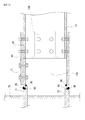
図9に示すように、まず、鋼管柱75に、垂直プレート16の非当接部16Aの先端面の上下部分をスポット的に溶接により仮付けする。
次いで、鋼管柱75の水平方向に突出形成された、上ダイヤフラム71の側面と上水平プレート11の下部に当接するように、裏当て金80を溶接により接合する。同様に下ダイヤフラム72側面と下水平プレート12の上部にも当接するように裏当て金80を溶接により接合する。
その後、図7に示すように、溶接部95、96を形成するように溶接して、上ダイヤフラム71の側面と上水平プレート11、下ダイヤフラム72の側面と下水平プレート12を確実に接合する。更に、鋼管柱75に垂直プレート16の非当接部16Aの先端面を溶接により本付けをして、柱梁接合ブラケット20の鋼管柱75への接合を完了する。
[Construction method]
The construction method will be described below by taking the column beam
(1) Joining the column-beam joint bracket to the steel pipe column As shown in FIG. 9, first, the upper and lower portions of the front end surface of the
Next, the backing
Thereafter, as shown in FIG. 7, welding is performed so as to form
(2)柱梁接合ブラケットへのH鋼梁の載置
柱梁接合ブラケット20へH鋼梁60を取り付けるには、図10に示すように、H鋼梁60の上フランジの先端面61eを、柱梁接合ブラケット20の上水平プレートの先端面11eと突合せると共に、H鋼梁60の下フランジの一端側を垂直プレート16の切欠き部16cに遊挿し、下水平プレート12上に載置する。その際、図9に示すように、垂直プレート16の当接部16B、及び垂直プレート16の段差部の端面に、ウェブ65の側面及び先端面をそれぞれ当接させる。
次いで、図10に示すように、下水平プレート12の貫通孔12hと下フランジの貫通孔62hとをボルト及びナット91で挿通固定する(図5参照。)。
(2) Placement of the H steel beam on the beam-to-column connection bracket To attach the
Next, as shown in FIG. 10, the through
(3)水平固定板の取付け
図9及び図10に示すように、柱梁接合ブラケット20の上水平プレート11とH鋼梁60の上フランジ61の上面に渡る水平固定板40を当接させる。
そして、上水平プレートの貫通孔11hと、水平固定板40の貫通孔40hを、ボルト及びナット91で挿通固定する(図5参照。)。
同様に、H鋼梁60の上フランジ61の貫通孔61hと、水平固定板40の貫通孔40nを、ボルト及びナット91で挿通固定する(図5参照。)。
(3) Attaching the horizontal fixing plate As shown in FIGS. 9 and 10, the upper
Then, the through
Similarly, the through
(4)垂直固定板の取付け
図9及び図10に示すように、垂直固定板50を、垂直プレート16の非当接部と、H鋼梁60のウェブ65に対して当接させる。
そして、垂直固定板50の貫通孔50hと、H鋼梁のウェブ65の貫通孔65hと、垂直プレート16の貫通孔16hとを、ボルト及びナット91で挿通固定する(図5参照。)。
更に、垂直プレート16の貫通孔16nと垂直固定板50の貫通孔50nとを、ボルト及びナット91で挿通固定する(図5参照。)。
以上の施工方法により、図5に示すように、本発明の柱梁接合ブラケットを用いた鋼管柱へのH鋼梁の取付けが完成する。
(4) Attaching the Vertical Fixing Plate As shown in FIGS. 9 and 10, the vertical fixing
Then, the through
Further, the through
With the above construction method, as shown in FIG. 5, the attachment of the H steel beam to the steel pipe column using the column beam joint bracket of the present invention is completed.
本発明の柱梁接合ブラケットは、鋼管柱に梁を接合固定する技術の分野において好適に利用される。 The column beam joint bracket of the present invention is suitably used in the field of technology for joining and fixing a beam to a steel pipe column.
10、20、30・・・柱梁接合ブラケット
11・・・・上水平プレート
11a・・・上水平プレートの上面
11s、12s、61s、62s・・・側端面
12・・・下水平プレート
12a・・下水平プレートのH鋼梁との当接面
15、16、17・・・垂直プレート
15A、16A・・・非接合部
15B、16B・・・当接部
15c、16c・・・切欠き部
16a・・垂直プレートのH鋼梁との当接面
18・・・段差
40・・・水平固定板
40a・・水平固定板の下面
50・・・垂直固定板
50a・・垂直固定板のH鋼梁との当接面
60・・・H鋼梁
61・・・上フランジ
62・・・下フランジ
65・・・ウェブ
70・・・ダイヤフラム
71・・・上ダイヤフラム
72・・・下ダイヤフラム
75・・・鋼管柱
10, 20, 30... Beam-to-column
Claims (5)
一端側が前記上ダイヤフラムに接合し、他端側が前記H鋼梁の上フランジと上面を面一に突き合わせる上水平プレートと、
前記上水平プレートに対向し、一端側が前記下ダイヤフラムに接合し、他端側に前記H鋼梁の下フランジを載置固定する下水平プレートと、
前記上水平プレートと前記下水平プレートを接続し、前記H鋼梁のウェブを当接固定する垂直プレートと、
前記上水平プレートと前記上フランジとを連結固定する水平固定板と、を備え、
前記垂直プレートの下部には、前記下フランジを遊挿するための切欠き部が形成されており、
前記垂直プレートの前記ウェブとの当接部は、非当接部との間に段差を有することにより、該非当接部の表面と該ウェブの表面とが面一に形成され、前記垂直プレートと前記ウェブとを連結固定する垂直固定板を備えたことを特徴とする柱梁接合ブラケット。 A column beam joint bracket for fixing an H steel beam to a pair of diaphragms formed by projecting in the horizontal direction of a steel pipe column and comprising an upper diaphragm and a lower diaphragm,
An upper horizontal plate having one end joined to the upper diaphragm and the other end abutting the upper flange and the upper surface of the H steel beam flush with each other;
A lower horizontal plate facing the upper horizontal plate, one end side of which is joined to the lower diaphragm, and the lower flange of the H steel beam is mounted and fixed to the other end side;
A vertical plate connecting the upper horizontal plate and the lower horizontal plate and abutting and fixing the web of the H steel beam;
A horizontal fixing plate for connecting and fixing the upper horizontal plate and the upper flange;
At the bottom of the vertical plate, a notch for loosely inserting the lower flange is formed ,
The contact portion of the vertical plate with the web has a step between the non-contact portion and the surface of the non-contact portion and the surface of the web are formed flush with each other. A column beam joint bracket comprising a vertical fixing plate for connecting and fixing the web .
The top flange and the side end faces of the upper horizontal plate and the side end faces of the bottom flange and the lower horizontal plate of claims 1 to 4 were all the positioning of the vertical plate so as to be flush The beam-column joint bracket according to any one of the above.
Priority Applications (1)
| Application Number | Priority Date | Filing Date | Title |
|---|---|---|---|
| JP2012176089A JP5950397B2 (en) | 2011-08-17 | 2012-08-08 | Column-beam joint bracket |
Applications Claiming Priority (3)
| Application Number | Priority Date | Filing Date | Title |
|---|---|---|---|
| JP2011178529 | 2011-08-17 | ||
| JP2011178529 | 2011-08-17 | ||
| JP2012176089A JP5950397B2 (en) | 2011-08-17 | 2012-08-08 | Column-beam joint bracket |
Publications (2)
| Publication Number | Publication Date |
|---|---|
| JP2013057233A JP2013057233A (en) | 2013-03-28 |
| JP5950397B2 true JP5950397B2 (en) | 2016-07-13 |
Family
ID=48133317
Family Applications (1)
| Application Number | Title | Priority Date | Filing Date |
|---|---|---|---|
| JP2012176089A Active JP5950397B2 (en) | 2011-08-17 | 2012-08-08 | Column-beam joint bracket |
Country Status (1)
| Country | Link |
|---|---|
| JP (1) | JP5950397B2 (en) |
Cited By (1)
| Publication number | Priority date | Publication date | Assignee | Title |
|---|---|---|---|---|
| CN106436924A (en) * | 2016-08-22 | 2017-02-22 | 广西建工集团第五建筑工程有限责任公司 | Steel pipe concrete column variable section broken-line-shaped steel bracket and connecting construction method thereof |
Families Citing this family (3)
| Publication number | Priority date | Publication date | Assignee | Title |
|---|---|---|---|---|
| JP6347593B2 (en) * | 2013-11-19 | 2018-06-27 | 大成建設株式会社 | Steel frame |
| JP7394381B2 (en) * | 2019-04-11 | 2023-12-08 | 構法開発株式会社 | Joint structure of H-beam steel |
| CN115419282B (en) * | 2022-10-08 | 2023-10-13 | 中建八局装饰工程有限公司 | Installation device for vertical member of steel structure and construction method thereof |
Family Cites Families (4)
| Publication number | Priority date | Publication date | Assignee | Title |
|---|---|---|---|---|
| JP3122209B2 (en) * | 1991-12-28 | 2001-01-09 | 大和ハウス工業株式会社 | Beam-column joint structure |
| JPH06158718A (en) * | 1992-11-20 | 1994-06-07 | Fujita Corp | Steel frame erection method without requiring fitting-up bolt |
| JPH0978692A (en) * | 1995-09-08 | 1997-03-25 | U S Kogyo:Kk | Square column connection block and beam for architectural frame and connection structure by use thereof |
| JP2001262699A (en) * | 2000-03-21 | 2001-09-26 | Arai Gumi Ltd | Connecting structure of steel pipe column and steel beam |
-
2012
- 2012-08-08 JP JP2012176089A patent/JP5950397B2/en active Active
Cited By (1)
| Publication number | Priority date | Publication date | Assignee | Title |
|---|---|---|---|---|
| CN106436924A (en) * | 2016-08-22 | 2017-02-22 | 广西建工集团第五建筑工程有限责任公司 | Steel pipe concrete column variable section broken-line-shaped steel bracket and connecting construction method thereof |
Also Published As
| Publication number | Publication date |
|---|---|
| JP2013057233A (en) | 2013-03-28 |
Similar Documents
| Publication | Publication Date | Title |
|---|---|---|
| JP4169086B2 (en) | Column beam connection structure, column beam connection method | |
| JP5950397B2 (en) | Column-beam joint bracket | |
| JP2009052302A (en) | Rigid joint structure of steel beam | |
| JP5080754B2 (en) | Method for assembling long material and assembly jig used in the method | |
| JP5764909B2 (en) | Steel sheet pile and steel sheet pile wall formed by the steel sheet pile | |
| KR20090062804A (en) | H beam connection | |
| JP6261976B2 (en) | Cross section beam | |
| JP2004257005A (en) | Beam-column connecting structure and beam-column connecting method | |
| JP6893799B2 (en) | Beam flint connection structure and beam flint connection piece | |
| JP6703303B2 (en) | Beam-column connection and beam-column joining method | |
| KR20140001316U (en) | Connecting structure for bracing joint part | |
| JP2006291531A (en) | Column / beam joint structure | |
| JPH03221636A (en) | Beam connecting structure | |
| JP5246443B2 (en) | Cylindrical steel end joint fitting and its joint structure | |
| JP2018188872A (en) | Joint structure for brace and column-beam | |
| JP2018162554A (en) | Column-beam jointing method and column-beam joint structure | |
| JP6799425B2 (en) | Adapter member and Yamadome support structure | |
| JP2007270559A (en) | Column/beam connection part structure of h-steel column | |
| JP4767617B2 (en) | Structure joint structure | |
| KR20120103532A (en) | Structure connecting device and assembly type structure having the same | |
| KR100917416B1 (en) | Steel Pipe Truss Cross Shape | |
| JP2007146365A (en) | Assembling method of pipe structure building, and assembling jig | |
| JP7018559B2 (en) | Casing support | |
| JP4667398B2 (en) | Scaffolding strut and horizontal stay connection device | |
| JP2006348734A (en) | Truss structure for construction |
Legal Events
| Date | Code | Title | Description |
|---|---|---|---|
| A621 | Written request for application examination |
Free format text: JAPANESE INTERMEDIATE CODE: A621 Effective date: 20150202 |
|
| A711 | Notification of change in applicant |
Free format text: JAPANESE INTERMEDIATE CODE: A711 Effective date: 20150202 |
|
| A521 | Request for written amendment filed |
Free format text: JAPANESE INTERMEDIATE CODE: A821 Effective date: 20150203 |
|
| A977 | Report on retrieval |
Free format text: JAPANESE INTERMEDIATE CODE: A971007 Effective date: 20151110 |
|
| A131 | Notification of reasons for refusal |
Free format text: JAPANESE INTERMEDIATE CODE: A131 Effective date: 20151124 |
|
| A521 | Request for written amendment filed |
Free format text: JAPANESE INTERMEDIATE CODE: A523 Effective date: 20151224 |
|
| TRDD | Decision of grant or rejection written | ||
| A01 | Written decision to grant a patent or to grant a registration (utility model) |
Free format text: JAPANESE INTERMEDIATE CODE: A01 Effective date: 20160601 |
|
| A61 | First payment of annual fees (during grant procedure) |
Free format text: JAPANESE INTERMEDIATE CODE: A61 Effective date: 20160603 |
|
| R150 | Certificate of patent or registration of utility model |
Ref document number: 5950397 Country of ref document: JP Free format text: JAPANESE INTERMEDIATE CODE: R150 |
|
| R250 | Receipt of annual fees |
Free format text: JAPANESE INTERMEDIATE CODE: R250 |
|
| R250 | Receipt of annual fees |
Free format text: JAPANESE INTERMEDIATE CODE: R250 |