JP5930809B2 - Sheet feeding apparatus and image forming apparatus - Google Patents
Sheet feeding apparatus and image forming apparatus Download PDFInfo
- Publication number
- JP5930809B2 JP5930809B2 JP2012086032A JP2012086032A JP5930809B2 JP 5930809 B2 JP5930809 B2 JP 5930809B2 JP 2012086032 A JP2012086032 A JP 2012086032A JP 2012086032 A JP2012086032 A JP 2012086032A JP 5930809 B2 JP5930809 B2 JP 5930809B2
- Authority
- JP
- Japan
- Prior art keywords
- gear
- sheet
- missing
- feeding
- driving
- Prior art date
- Legal status (The legal status is an assumption and is not a legal conclusion. Google has not performed a legal analysis and makes no representation as to the accuracy of the status listed.)
- Expired - Fee Related
Links
Images


Classifications
-
- B—PERFORMING OPERATIONS; TRANSPORTING
- B65—CONVEYING; PACKING; STORING; HANDLING THIN OR FILAMENTARY MATERIAL
- B65H—HANDLING THIN OR FILAMENTARY MATERIAL, e.g. SHEETS, WEBS, CABLES
- B65H3/00—Separating articles from piles
- B65H3/02—Separating articles from piles using friction forces between articles and separator
- B65H3/06—Rollers or like rotary separators
- B65H3/0669—Driving devices therefor
-
- B—PERFORMING OPERATIONS; TRANSPORTING
- B65—CONVEYING; PACKING; STORING; HANDLING THIN OR FILAMENTARY MATERIAL
- B65H—HANDLING THIN OR FILAMENTARY MATERIAL, e.g. SHEETS, WEBS, CABLES
- B65H1/00—Supports or magazines for piles from which articles are to be separated
- B65H1/08—Supports or magazines for piles from which articles are to be separated with means for advancing the articles to present the articles to the separating device
- B65H1/12—Supports or magazines for piles from which articles are to be separated with means for advancing the articles to present the articles to the separating device comprising spring
-
- B—PERFORMING OPERATIONS; TRANSPORTING
- B65—CONVEYING; PACKING; STORING; HANDLING THIN OR FILAMENTARY MATERIAL
- B65H—HANDLING THIN OR FILAMENTARY MATERIAL, e.g. SHEETS, WEBS, CABLES
- B65H1/00—Supports or magazines for piles from which articles are to be separated
- B65H1/08—Supports or magazines for piles from which articles are to be separated with means for advancing the articles to present the articles to the separating device
- B65H1/14—Supports or magazines for piles from which articles are to be separated with means for advancing the articles to present the articles to the separating device comprising positively-acting mechanical devices
-
- B—PERFORMING OPERATIONS; TRANSPORTING
- B65—CONVEYING; PACKING; STORING; HANDLING THIN OR FILAMENTARY MATERIAL
- B65H—HANDLING THIN OR FILAMENTARY MATERIAL, e.g. SHEETS, WEBS, CABLES
- B65H3/00—Separating articles from piles
- B65H3/02—Separating articles from piles using friction forces between articles and separator
- B65H3/06—Rollers or like rotary separators
- B65H3/0607—Rollers or like rotary separators cooperating with means for automatically separating the pile from roller or rotary separator after a separation step
-
- B—PERFORMING OPERATIONS; TRANSPORTING
- B65—CONVEYING; PACKING; STORING; HANDLING THIN OR FILAMENTARY MATERIAL
- B65H—HANDLING THIN OR FILAMENTARY MATERIAL, e.g. SHEETS, WEBS, CABLES
- B65H3/00—Separating articles from piles
- B65H3/02—Separating articles from piles using friction forces between articles and separator
- B65H3/06—Rollers or like rotary separators
- B65H3/0684—Rollers or like rotary separators on moving support, e.g. pivoting, for bringing the roller or like rotary separator into contact with the pile
-
- B—PERFORMING OPERATIONS; TRANSPORTING
- B65—CONVEYING; PACKING; STORING; HANDLING THIN OR FILAMENTARY MATERIAL
- B65H—HANDLING THIN OR FILAMENTARY MATERIAL, e.g. SHEETS, WEBS, CABLES
- B65H5/00—Feeding articles separated from piles; Feeding articles to machines
- B65H5/06—Feeding articles separated from piles; Feeding articles to machines by rollers or balls, e.g. between rollers
- B65H5/068—Feeding articles separated from piles; Feeding articles to machines by rollers or balls, e.g. between rollers between one or more rollers or balls and stationary pressing, supporting or guiding elements
-
- B—PERFORMING OPERATIONS; TRANSPORTING
- B65—CONVEYING; PACKING; STORING; HANDLING THIN OR FILAMENTARY MATERIAL
- B65H—HANDLING THIN OR FILAMENTARY MATERIAL, e.g. SHEETS, WEBS, CABLES
- B65H7/00—Controlling article feeding, separating, pile-advancing, or associated apparatus, to take account of incorrect feeding, absence of articles, or presence of faulty articles
- B65H7/20—Controlling associated apparatus
-
- B—PERFORMING OPERATIONS; TRANSPORTING
- B65—CONVEYING; PACKING; STORING; HANDLING THIN OR FILAMENTARY MATERIAL
- B65H—HANDLING THIN OR FILAMENTARY MATERIAL, e.g. SHEETS, WEBS, CABLES
- B65H2402/00—Constructional details of the handling apparatus
- B65H2402/50—Machine elements
- B65H2402/54—Springs, e.g. helical or leaf springs
-
- B—PERFORMING OPERATIONS; TRANSPORTING
- B65—CONVEYING; PACKING; STORING; HANDLING THIN OR FILAMENTARY MATERIAL
- B65H—HANDLING THIN OR FILAMENTARY MATERIAL, e.g. SHEETS, WEBS, CABLES
- B65H2403/00—Power transmission; Driving means
- B65H2403/40—Toothed gearings
- B65H2403/42—Spur gearing
- B65H2403/421—Spur gearing involving at least a gear with toothless portion
-
- B—PERFORMING OPERATIONS; TRANSPORTING
- B65—CONVEYING; PACKING; STORING; HANDLING THIN OR FILAMENTARY MATERIAL
- B65H—HANDLING THIN OR FILAMENTARY MATERIAL, e.g. SHEETS, WEBS, CABLES
- B65H2403/00—Power transmission; Driving means
- B65H2403/50—Driving mechanisms
- B65H2403/51—Cam mechanisms
- B65H2403/512—Cam mechanisms involving radial plate cam
-
- B—PERFORMING OPERATIONS; TRANSPORTING
- B65—CONVEYING; PACKING; STORING; HANDLING THIN OR FILAMENTARY MATERIAL
- B65H—HANDLING THIN OR FILAMENTARY MATERIAL, e.g. SHEETS, WEBS, CABLES
- B65H2403/00—Power transmission; Driving means
- B65H2403/70—Clutches; Couplings
- B65H2403/72—Clutches, brakes, e.g. one-way clutch +F204
- B65H2403/725—Brakes
-
- B—PERFORMING OPERATIONS; TRANSPORTING
- B65—CONVEYING; PACKING; STORING; HANDLING THIN OR FILAMENTARY MATERIAL
- B65H—HANDLING THIN OR FILAMENTARY MATERIAL, e.g. SHEETS, WEBS, CABLES
- B65H2404/00—Parts for transporting or guiding the handled material
- B65H2404/10—Rollers
- B65H2404/11—Details of cross-section or profile
- B65H2404/111—Details of cross-section or profile shape
- B65H2404/1112—D-shape
Landscapes
- Engineering & Computer Science (AREA)
- Mechanical Engineering (AREA)
- Sheets, Magazines, And Separation Thereof (AREA)
Description
本発明は、シート給送装置及び画像形成装置に関し、特にシート給送時、シートが給送ローラに当接する際の騒音を低減させるための構成に関する。 The present invention relates to a sheet feeding apparatus and an image forming apparatus, and more particularly to a configuration for reducing noise when a sheet comes into contact with a feeding roller during sheet feeding.
従来、複写機やプリンタ等の画像形成装置は、シートを画像形成部に向けて送り出すシート給送装置を備えている。このようなシート給送装置としては、昇降可能な中板と、給送ローラとを備え、給送ローラの回転により中板を上昇させて中板上のシートを給送ローラに押し付け、この状態で給送ローラが回転することにより、シートを送り出すようにしている。 2. Description of the Related Art Conventionally, an image forming apparatus such as a copying machine or a printer includes a sheet feeding device that feeds a sheet toward an image forming unit. Such a sheet feeding device includes a middle plate that can be raised and lowered, and a feeding roller. The middle plate is raised by rotation of the feeding roller and the sheet on the middle plate is pressed against the feeding roller. The sheet is fed out by rotating the feeding roller.
ここで、このように給送ローラの回転により中板を上昇させるための構成としては、例えば給送ローラの回転軸にカムを固定し、このカムをバネにより付勢された中板に設けられた圧接部に圧接させるようにしたものがある(特許文献1及び2参照)。そして、給送動作が始まると、カムの回転によって中板を付勢しているバネのバネ圧を開放させながら中板を上昇させ、中板上のシートを給送ローラに押し付ける。 Here, as a configuration for raising the intermediate plate by the rotation of the feeding roller in this way, for example, a cam is fixed to the rotating shaft of the feeding roller, and this cam is provided on the intermediate plate biased by a spring. There are some which are brought into pressure contact with the pressure contact portion (see Patent Documents 1 and 2). Then, when the feeding operation starts, the middle plate is raised while releasing the spring pressure of the spring urging the middle plate by the rotation of the cam, and the sheet on the middle plate is pressed against the feeding roller.
ところで、このような従来のシート給送装置においては、カムの回転によって中板が上昇するときの上昇速度は、中板を付勢しているバネ力とカムの外周形状(プロファイル)により決まる。また、中板の上昇速度、言い換えれば積載されたシートの最上位シートが給送ローラに当接する速度は、中板上のシート積載量によって変化し、積載量が少ない場合は、積載量が多い場合よりも、速度が増加する。そして、このように最上位シートが給送ローラに当接する速度が増加した場合、シートが給送ローラに当接する際、当接音(衝突音)が発生する。 By the way, in such a conventional sheet feeding apparatus, the rising speed when the intermediate plate is raised by the rotation of the cam is determined by the spring force urging the intermediate plate and the outer peripheral shape (profile) of the cam. In addition, the rising speed of the middle plate, in other words, the speed at which the uppermost sheet of the stacked sheets abuts on the feeding roller varies depending on the sheet loading amount on the middle plate, and when the loading amount is small, the loading amount is large. More than the case, the speed increases. When the speed at which the uppermost sheet contacts the feeding roller increases as described above, a contact sound (collision sound) is generated when the sheet contacts the feeding roller.
ここで、この当接音(衝突音)を低減するためには、カムの回転速度、言い換えれば給送ローラの回転速度を遅くして中板の上昇速度を遅くすれば良い。なお、給送ローラの回転速度を遅くした場合、シートに適切に画像を形成することができなくおそれがあるが、この後、給送ローラの回転速度を画像形成装置の印刷速度(プロセススピード)まで上げるようにすれば、シート上に適切に画像を形成することができる。 Here, in order to reduce the contact noise (collision noise), the rotation speed of the cam, in other words, the rotation speed of the feeding roller may be decreased to decrease the rising speed of the intermediate plate. Note that if the rotation speed of the feeding roller is decreased, it may not be possible to properly form an image on the sheet. Thereafter, the rotation speed of the feeding roller is set to the printing speed (process speed) of the image forming apparatus. If the height is increased, an image can be appropriately formed on the sheet.
しかし、このような速度制御を可能とするには、給送ローラを専用の駆動源により駆動する必要があるが、通常、駆動源は、作像系や搬送系等、他の駆動源を兼ねている場合が多く、この場合、給送ローラは一定速度でしか回転することができない。このため、給送ローラの回転速度だけを遅くすることができず、また印刷速度が増加すれば、給送ローラの回転速度も増加し、これに伴い中板の上昇速度も増加する。 However, in order to enable such speed control, it is necessary to drive the feeding roller with a dedicated drive source. Usually, the drive source also serves as another drive source such as an image forming system or a conveyance system. In this case, the feeding roller can only rotate at a constant speed. For this reason, only the rotation speed of the feeding roller cannot be reduced, and if the printing speed increases, the rotation speed of the feeding roller also increases, and accordingly, the rising speed of the intermediate plate also increases.
つまり、従来のシート給送装置において、給送ローラの駆動源は他の駆動源を兼ねているため、回転軸の回転速度を任意に変更して当接音を緩和することはできない。このため、さらに、中板の昇降速度はカムのプロファイルに依存するが、カムの外周形状だけで中板上昇速度の低減領域を十分確保するのには限界がある。 That is, in the conventional sheet feeding apparatus, the driving source of the feeding roller also serves as another driving source, and therefore the contact noise cannot be reduced by arbitrarily changing the rotational speed of the rotating shaft. For this reason, the ascending / descending speed of the intermediate plate depends on the profile of the cam, but there is a limit to securing a sufficient reduction area of the intermediate plate ascending speed only by the outer peripheral shape of the cam.
そこで、本発明は、このような現状に鑑みてなされたものであり、シートが給送ローラへ当接する時の衝突音を低減すると共にシートに適切に画像を形成することのできるシート給送装置及び画像形成装置を提供することを目的とするものである。 Accordingly, the present invention has been made in view of such a situation, and a sheet feeding apparatus capable of reducing a collision sound when the sheet contacts the feeding roller and appropriately forming an image on the sheet. An object of the present invention is to provide an image forming apparatus.
本発明は、シート給送装置において、シートを支持する昇降可能なシート積載板と、前記シート積載板の上方に設けられ、前記シート積載板に支持されたシートを給送する給送ローラと、前記シート積載板を前記給送ローラの方向に付勢し、前記シート積載板に積載されたシートを前記給送ローラに押し付ける付勢部と、前記給送ローラを駆動する駆動部と、前記給送ローラの軸に設けられたカム、及び前記シート積載板に設けられて前記カムに圧接する圧接部を有し、前記付勢部により付勢された前記シート積載板を前記カムに前記圧接部を圧接させながら前記給送ローラの軸の回転に伴って昇降させる昇降部と、前記駆動部により駆動されて回転する入力軸に固定され、駆動小ギア及び駆動大ギアを有する駆動ギアと、前記給送ローラの軸に固定され、欠歯小ギア及び欠歯大ギアを有する欠歯ギアとを有し、前記駆動部により駆動されて回転する前記駆動小ギアが前記欠歯大ギアと噛合することで第1の速度で前記給送ローラの軸を回転させて前記シート積載板を上昇させ、前記積載板に積載されたシートが前記給送ローラに当接すると、前記駆動部により駆動されて回転する前記駆動大ギアが前記欠歯小ギアと噛合することで前記第1の速度よりも速い第2の速度で前記給送ローラの軸を回転させる変速部と、前記欠歯ギアを、前記給送ローラを回転させる方向に回転するように付勢し、シートの給送が開始されると、前記欠歯ギアを前記欠歯大ギアが前記駆動小ギアと噛合するように回転させるギア付勢部と、を備えたことを特徴とするものである。 The present invention relates to a sheet feeding apparatus, a sheet stacking plate that can move up and down to support the sheet, a feeding roller that is provided above the sheet stacking plate and feeds the sheet supported by the sheet stacking plate, The urging unit that urges the sheet stacking plate in the direction of the feeding roller and presses the sheets stacked on the sheet stacking plate against the feeding roller, a drive unit that drives the feeding roller, and the feeding unit A cam provided on the shaft of the feed roller; and a pressure contact portion provided on the sheet stacking plate and pressed against the cam; and the sheet stacking plate biased by the biasing portion is placed on the cam. An elevating part that moves up and down with the rotation of the shaft of the feeding roller while being in pressure contact with each other , a driving gear that is fixed to an input shaft that is driven and rotated by the driving part , and that has a driving small gear and a driving large gear, Feeding roller It is secured to, and a segment gear having a toothless small gear and toothless large gear, the driving small gear which rotates by being driven by the drive unit is the toothless large gear and by meshing the first When the shaft of the feeding roller is rotated at a speed to raise the sheet stacking plate and the sheets stacked on the stacking plate come into contact with the feeding roller, the driving unit is driven and rotated by the driving unit. A gear that meshes with the small toothless small gear to rotate the shaft of the feeding roller at a second speed that is faster than the first speed , and the toothless gear that rotates the feeding roller. A gear urging unit that urges the gear to rotate in the direction of rotation, and rotates the missing tooth gear so that the missing tooth large gear meshes with the driving small gear when sheet feeding is started. It is characterized by having.
本発明によれば、変速部が、駆動部の駆動を受けて、第1の速度で給送ローラの軸を回転させてシート積載板を上昇させ、シート積載板に積載されたシートが給送ローラに当接すると、第1の速度よりも速い第2の速度で給送ローラの軸を回転させる。したがって、シート積載板を遅い速度で上昇させ、シートが給送ローラに押し付けられると、給送ローラを速い速度で回転させることができ、シートが給送ローラへ当接する時の衝突音を低減すると共にシートに適切に画像を形成することができる。 According to the present invention, the transmission unit receives the drive of the driving unit, rotates the shaft of the feeding roller at the first speed to raise the sheet stacking plate, and feeds the sheets stacked on the sheet stacking plate. When contacting the roller, the shaft of the feed roller is rotated at a second speed higher than the first speed. Therefore, when the sheet stacking plate is raised at a slow speed and the sheet is pressed against the feeding roller, the feeding roller can be rotated at a high speed, and the collision noise when the sheet comes into contact with the feeding roller is reduced. In addition, an image can be appropriately formed on the sheet.
以下、本発明の実施の形態について図面を用いて詳細に説明する。図1は、本発明の第1の実施の形態に係るシート給送装置を備えた画像形成装置の一例であるプリンタの概略構成を示す図である。図1において、1はプリンタ、1Aは装置本体であるプリンタ本体、5はプリンタ本体1Aに設けられ、電子写真方式により画像形成を行う画像形成部、1Bは画像形成部5にシートSを給送するシート給送装置である。
Hereinafter, embodiments of the present invention will be described in detail with reference to the drawings. FIG. 1 is a diagram illustrating a schematic configuration of a printer that is an example of an image forming apparatus including a sheet feeding device according to a first embodiment of the present invention. In FIG. 1, 1 is a printer, 1A is a printer main body which is a main body of the apparatus, 5 is provided in the printer
ここで、画像形成部5はレーザ露光装置5b、トナー像を形成する感光体ドラム5a、感光体ドラム5aに形成されたトナー像をシートSに転写する転写ローラ5d等を備えている。なお、5Aは感光体ドラム5a、現像手段5c等を備えたプロセスカートリッジであり、このプロセスカートリッジ5Aは、プリンタ本体1Aに着脱自在に装着されている。
The
シート給送装置1Bは、給送ローラ3と、シート収納部である給紙トレイ2と、給紙トレイ2に昇降可能に設けられ、給紙トレイ2に収納されたシートSを給送ローラ3に押圧するシート積載板である中板9とを備えている。また、給紙トレイ2のシート給送方向下流側には、給送ローラ3に圧接する分離パッド10が設けられている。
The sheet feeding apparatus 1 </ b> B is provided with a
そして、このようなシート給送装置1Bにおいては、画像形成の際には給送ローラ3により給紙トレイ2からシートSを送り出し、この後、シートSを、給送ローラ3に圧接している分離パッド10により1枚ずつ分離するようにしている。なお、この分離パッド10は、中板9の下部に回動支点10bを有する分離パッド保持部10cの回動端に保持されると共に、コイルバネ10aにより給送ローラ3に向けて付勢されている。
In such a
次に、このような構成のプリンタ1における画像形成動作について説明する。画像形成動作が開始されると、まず給送ローラ3が回転し、この給送ローラ3の回転に伴って中板9が上昇する。そして、中板9に積載されたシートSが、給送ローラ3に押し付けられ、この後、シートSは給送ローラ3の回転により送り出される。次に、シートSは分離パッド10によって1枚ずつ分離された後、搬送ローラ対4により搬送される。この後、シートSの先端がセンサT1により検知されると、レーザ露光装置5bから画像信号に応じたレーザ光が、表面が帯電処理されると共に、矢印方向に回転駆動されている感光体ドラム5aに照射される。
Next, an image forming operation in the printer 1 having such a configuration will be described. When the image forming operation is started, the
そして、このような画像信号に応じた光が照射されることにより、感光体ドラム上に潜像が形成され、この感光体ドラム上の潜像は、現像手段5cにより供給されたトナーにより現像され、トナー像として可視化される。この後、シートSが転写ローラ5dと感光体ドラム5aとにより形成される転写部に搬送されると、可視化されたトナー像は、転写ローラ5dに感光体ドラム5aに形成されたトナー像と逆極性の電圧を印加することにより、シートSに転写される。
By irradiating light corresponding to such an image signal, a latent image is formed on the photosensitive drum, and the latent image on the photosensitive drum is developed by the toner supplied by the developing
次に、トナー像が転写されたシートSはプリンタ本体上部に配置された定着手段5eへと搬送される。そして、この定着手段5eを通過する際、シートSに熱及び圧力を加えられることにより、シート上に転写トナー像が定着される。この後、トナー像が定着されたシートSは排出ローラ対7により搬送され、プリンタ本体1Aの上面に形成した排出部8へと排出される。なお、図1において、Mは給送ローラ3等を駆動する駆動部であるメインモータであり、このメインモータMの駆動は、駆動ギア列等の不図示の駆動伝達手段を介して給送ローラ3、搬送ローラ対4、感光体ドラム5a、定着手段5e、排紙ローラ対7に伝達される。また、図1において、50は、メインモータM、後述するソレノイド14等の動作を制御する制御部である。
Next, the sheet S to which the toner image has been transferred is conveyed to a
ここで、本実施の形態において、シート給送装置1Bの給送ローラ3は、図2に示すように、円周面の一部が切り欠かれたゴム部3aを回転軸6に固定した構成のものである。また、中板9はシート給送方向と直交する幅方向の両端に垂設された側壁部9Aのシート給送方向上流側に設けられた支点9cを介して給紙トレイ2に上下方向に回動自在に支持されており、シートは先端を、中板9の回動端9dに合わせて中板上にセットされる。また、この中板9は、シート給送方向下流側の幅方向両端部の下方に配された付勢部材であるコイルバネ9aにより、給送ローラ3に向けて付勢されている。
Here, in the present embodiment, the feeding
回転軸6には幅方向の両端にカム11が固定され、中板9の側壁部9Aのシート給送方向下流側の上面には、それぞれ左右のカム11と当接する圧接部9bが形成されている。そして、回転軸6が回転してカム11が回転することにより、中板9が昇降する。つまり、本実施の形態においては、カム11及び中板9の圧接部9bにより、給送ローラ3の回転軸6の回転に伴ってコイルバネ9aにより付勢された中板9を昇降させる昇降部11Aが構成される。
また、この回転軸6の、一方のカム11の外側には、欠歯部を有する欠歯ギアである給紙欠歯段ギア12が固定されている。なお、給紙欠歯段ギア12は、ソレノイド14により回転が規制されており、ソレノイド14による規制が解除されると、メインモータMから駆動伝達手段を介して回転駆動力が伝達される入力軸13aに固定されている入力段ギア13と噛合する。
Further, on the outer side of one
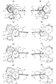
ここで、駆動ギアである入力段ギア13は、図3に示すように、駆動大ギアである大ギア13bと、駆動小ギアである小ギア13cを一体に備えた段ギアであり、入力軸13aと一体に一定速度でR2方向へ回転している。また、給紙欠歯段ギア12は、欠歯大ギア12a、カム面12b及び欠歯小ギア12cを有している。そして、本実施の形態においては、メインモータMと昇降部11Aの間に設けられ、入力段ギア13と給紙欠歯段ギア12とにより構成される変速部19が回転軸6の回転速度を第1の速度から第1の速度よりも速い第2の速度に変化させる。これにより、給送ローラ3の回転速度及び中板9の上昇速度を変化させる。
Here, as shown in FIG. 3, the
なお、図3において、15は一端が給紙欠歯段ギア12の欠歯小ギア12cの側面に形成された係止部12eに係止され、他端がプリンタ本体1Aの不図示のフレームに設けられた固定軸27に係止されている給紙ギアバネである。そして、このギア付勢部を構成する給紙ギアバネ15により、給紙欠歯段ギア12はR1の方向、すなわち給送ローラ3をシート給送方向に回転させる方向に回転するように付勢されている。
In FIG. 3, one
図3の(a)及び、図3の(a)を入力段ギア13側から見た図である図3の(b)は、シート給送動作が開始される前の状態を示している。このとき、給紙欠歯段ギア12の欠歯大ギア12a及び欠歯小ギア12cは、入力段ギア13の大ギア13b及び小ギア13cとは噛合していない。
3A and FIG. 3B, which is a view of FIG. 3A viewed from the
なお、このとき給紙ギアバネ15の張力により、給紙欠歯段ギア12は破線で示したR1方向への回転力が付与されているが、図3の(a)に示すように給紙欠歯段ギア12の段差部12dにはソレノイド14の係止爪14aが係止されている。これにより、給紙欠歯段ギア12は、欠歯大ギア12a及び欠歯小ギア12cが、入力段ギア13の大ギア13bと、小ギア13cとは噛合していない状態、すなわち停止(給紙待機)状態に保持される。
At this time, due to the tension of the paper
また、図4の(a)は、中板9が給紙前の初期位置に有る状態を示している。このとき、中板9は支点9cを中心に圧接部9bをカム11により、コイルバネ9aを圧縮しながら押し下げられており、これにより中板9上のシートSの先端部は給送ローラ3に対して離間している。
FIG. 4A shows a state in which the
次に、シート給送動作が開始されると、制御部50はソレノイド14をONし、図4の(b)に示すように、係止爪14aの係止を外す。これにより、図3の(c)及び(d)に示すように、給紙欠歯段ギア12は給紙ギアバネ15の張力によりR1方向へ回転を開始する。そして、メインモータMの駆動を受けて矢印R2方向へ回転駆動している入力段ギア13の小ギア13cに、給紙欠歯段ギア12の欠歯大ギア12aが噛合する。
Next, when the sheet feeding operation is started, the
そして、このように給紙欠歯段ギア12の欠歯大ギア12aが入力段ギア13の小ギア13cと噛合することで、図4の(b)に示すように回転軸6に矢印R3方向への回転駆動が伝わり、カム11が所定角度回転する。このとき、給紙欠歯段ギア12の欠歯大ギア12aが入力段ギア13の小ギア13cと噛合しているので、入力段ギア13の回転に対して、給紙欠歯段ギア12及びカム11はゆっくり回転する。即ち、回転軸6及びカム11は、比較的遅い速度である第1の速度で回転する。そして、このようにカム11がゆっくり回転すると、カム11により圧縮されていたコイルバネ9aがゆっくり開放されるようになるので、中板9も減速しながら上昇し、中板9上のシートSも給送ローラ3にゆっくりと当接する。この結果、シートSが給送ローラ3へ当接する時の衝突音が低減する。
In this way, when the
なお、このとき、図3の(d)に示すように入力段ギア13の大ギア13bと、給紙欠歯段ギア12の欠歯小ギア12cはまだ噛合していない。また、給紙欠歯段ギア12が回転を開始すると、ソレノイド14をOFFする。これにより、係止爪14aは戻されて給紙欠歯段ギア12のカム面12b上に当接し、次に段差部12dが回ってきたときに段差部12dを係止し、再び給紙欠歯段ギア12を係止する。
At this time, as shown in FIG. 3 (d), the
次に、中板9が上昇しきると、図3の(e)に示すように、給紙欠歯段ギア12の欠歯大ギア12aと、入力段ギア13の小ギア13cとの噛合が終了する。なお、このとき、図3の(f)に示すように、給紙欠歯段ギア12の欠歯小ギア12cと入力段ギア13の大ギア13bはまだ噛合していない。
Next, when the
ここで、このときまだ給紙ギアバネ15は伸びた状態で張力を発揮しているので、この後、給紙ギアバネ15により、給紙欠歯段ギア12は回転を続け、やがて給紙欠歯段ギア12の欠歯小ギア12cが入力段ギア13の大ギア13bに噛合する。これにより、図4の(c)に示すように回転軸6に再び回転力が伝わる。
At this time, since the paper
ここで、このように給紙欠歯段ギア12の欠歯小ギア12cが入力段ギア13の大ギア13bに噛合した場合、入力段ギア13の回転速度に対して給紙欠歯段ギア12が速く回転する。即ち、回転軸6及び給送ローラ3は、第1の速度よりも速い第2の速度で回転する。なお、本実施の形態においては、このときの給紙欠歯段ギア12の回転速度はプリンタ本体1Aのプロセス速度と同等である。そして、このような回転速度で回転する給送ローラ3によって送り出された最上位シートは、図2に示す分離パッド10と給送ローラ3により一枚だけ分離された後、給送ローラ3によりプロセス速度で搬送ローラ対4に送り出され、画像形成部5に向けて搬送される。
Here, when the
次に、送り出されたシートが搬送ローラ対4に達した後、給送ローラ3と分離パッド10によるシートSの分離作業が終わり、搬送ローラ対4にシートSが渡されると、図5の(a)及び(b)に示すように、カム11が中板9の圧接部9bを下方に押圧する。これにより、中板9が下降し、中板上のシートSは給送ローラ3から離間する。
Next, after the fed sheet reaches the conveying
この後、給紙欠歯段ギア12が、図3の(h)に示すように入力段ギア13の大ギア13bと、給紙欠歯段ギア12の欠歯小ギア13cの噛合が終了する位置まで回転すると、給紙欠歯段ギア12には回転駆動力が伝達されなくなる。なお、このとき、図3の(g)に示すように、入力段ギア13の小ギア13cと給紙欠歯段ギア12の欠歯大ギア12aは噛合していない。
Thereafter, the engagement of the
しかし、このように給紙欠歯段ギア12の回転駆動力がなくなった場合でも、まだ給紙ギアバネ15が伸びた状態にある。このため、この後、給紙ギアバネ15の張力により給紙欠歯段ギア12はR1方向へ回転し、入力段ギア13の小ギア13cと給紙欠歯段ギア12の欠歯大ギア12aが噛合する。これにより、給紙欠歯段ギア12が回転し、やがて図3の(a)と同じ初期位置に復帰する。このとき、給紙欠歯段ギア12は、入力段ギア13とは噛合せず、かつ給紙ギアバネ15によりR1方向に張力を受けつつ、ソレノイド14の係止爪14aにより係止される。
However, even when the rotational driving force of the paper
ところで、連続した複数枚の印刷ジョブが入っているとき、先行シートと後続シートの紙間設定が短くなる場合がある。この場合には、図4の(b)に示すように、給紙欠歯段ギア12並びにカム11が初期位置に戻った時点で、先行シートの後端がまだシート給送装置内に残ったまま、次のシートの給送動作が始まる。この時点では、シートSと給送ローラ3は離間されており、給送ローラ3と分離パッド10は当接していない。このため、先行シートは搬送ローラ対4の搬送力で送り出されるようになり、次のシートが給送ローラ3へ当接して給送ローラ3による給送動作が始まる時には、先行シートの後端は給送部を抜けている。
By the way, when there are a plurality of continuous print jobs, the setting between the preceding sheet and the succeeding sheet may be shortened. In this case, as shown in FIG. 4B, the trailing edge of the preceding sheet still remains in the sheet feeding device when the
なお、図6は、本実施の形態に係るシート給送装置1Bのシート給送動作の流れを、カム11と中板(シート)の位置、ソレノイド14のON,OFF、給紙欠歯段ギア12、入力段ギア13の回転を用いて説明した図である。また、図7は、カム11の回転による進角にあわせて、ソレノイド14、ギア12,13の噛合、カム11の回転、中板9の昇降、シート給送の、それぞれのタイミングを示した図である。
6 shows the flow of the sheet feeding operation of the
そして、図6の模式図を上から順に、また図7のタイミングチャートをカム回転角度0°位置から右へ順に追って説明すると、ソレノイド14の動作(ON)をきっかけに、給紙欠歯段ギア12の欠歯大ギア12aが入力段ギア13の小ギア13cと噛合する。なお、このとき、入力段ギア13は常時回転駆動されている。そして、このように給紙欠歯段ギア12の欠歯大ギア12aが入力段ギア13の小ギア13cと噛合すると、カム11がゆっくり回り、回転軸6を遅回しする。これにより、中板9がゆっくり上昇する。
6 will be described in order from the top, and the timing chart in FIG. 7 will be described in order from the cam rotation angle 0 ° position to the right. The twelve missing
次に、カム11と中板9の圧接部9bとの圧接が解除され、上昇した中板9が給送ローラ3によるシートの給送が可能な給紙分離位置に達すると、給紙欠歯段ギア12の欠歯大ギア12aの入力段ギア13の小ギア13cとの噛合が終了する。これにより、カム11の回転が停止し、これに伴い中板9の上昇が完了する。この後、給紙欠歯段ギア12の欠歯小ギア12cと入力段ギア13の大ギア13bの噛合に切り替わる。これにより、カム11が回転を開始すると共にカム11及び回転軸6が早回しされる。
Next, when the press contact between the
これにより、給送ローラ3は、所定のプロセス速度で最上位シートを分離して搬送ローラ対4へ送り出すと共に、中板9は下降する。さらに、カム11が回転して中板9を押し下げ、給紙欠歯段ギア12が欠歯位置に達して噛合を終了すると、入力段ギア13からの駆動が切れ、カム11及び中板9は初期位置に復帰する。なお、図6及び図7は、連続した複数枚の印刷ジョブが入っており、先行シートと後続シートの紙間設定を短くした場合、先行シートの後端が給紙部から抜ける前に次の給送動作が開始されるタイミングを示している。
As a result, the feeding
以上説明したように、本実施の形態では、シート給送動作が開始されると、まずカム11の回転速度が遅くなる減速比となるように給紙欠歯段ギア12と入力段ギア13とを噛合させるようにしている。また、給送ローラ3によるシートの分離と搬送ローラ対4への送り出し時には、給送ローラ3を所定のプロセススピードで回転させるような減速比で給紙欠歯段ギア12と入力段ギア13とを噛合させるようにしている。
As described above, in the present embodiment, when the sheet feeding operation is started, first, the sheet feeding missing
そして、このように中板上昇時の回転軸6及びカム11の回転速度を比較的遅い第1の速度とすることにより、中板9の上昇速度を遅くすることができ、この結果、中板上のシートが給送ローラ3へ当接する時の衝突音を低減することができる。また、シートの分離給送動作の際には、回転軸6及び給送ローラ3の回転速度を第1の速度よりも速い第2の速度に増速することにより、給送ローラ3を所定のプロセススピードで回転させることができる。
In this way, by setting the rotational speed of the
つまり、本実施の形態においては、一定速度で回転する入力段ギア13に対して給紙欠歯段ギア12を噛合させることにより、カム11(入力段ギア13)の1回転駆動により上昇する中板9の上昇速度を遅くさせることができる。これにより、独立した駆動源をもたない、もしくは一定速度の回転駆動しか供給出来ない駆動源を持つ場合でも、中板上のシートが給送ローラ3へ当接する時の衝突音を低減することができ、静粛性の優れたシート給送装置を提供することができる。
In other words, in the present embodiment, the
次に、本発明の第2の実施の形態について説明する。図8は、本実施の形態に係るシート給送装置の構成を説明する図である。なお、本実施の形態において、図3と同一符号は、同一又は相当部分を示している。 Next, a second embodiment of the present invention will be described. FIG. 8 is a diagram illustrating the configuration of the sheet feeding apparatus according to the present embodiment. In the present embodiment, the same reference numerals as those in FIG. 3 indicate the same or corresponding parts.
図8において、16は給紙欠歯段ギアであり、この給紙欠歯段ギア16は、欠歯大ギア16aと、カム面16bと、欠歯小ギア16cとを備えている。なお、図8の(a)及び(b)は中板9が上昇し、入力段ギア13の小ギア13cと給紙欠歯段ギア16の欠歯大ギア16aの噛合が終了し、入力段ギア13の大ギア13bと給紙欠歯段ギア16の欠歯小ギア16cに噛合が切り替わる瞬間を示している。
In FIG. 8,
ここで、本実施の形態において、入力段ギア13は小ギア13cの噛合終了と、大ギア13bの噛合開始の位相が一致するような関係にある。例えば、ギアのモジュールが1の場合、大ギア13bの歯数は小ギア13cの歯数の整数倍になるように設定した上で、大ギア13bと小ギア13cの、給紙欠歯段ギア16に対する噛み合いの切り替え位相を設定している。
Here, in the present embodiment, the
一方、入力段ギア13と噛合する、給紙欠歯ギア16の欠歯大ギア16aと欠歯小ギア16cも同様の関係となっている。さらに、給紙欠歯ギア16は、欠歯大ギア16aの噛み終わりと欠歯小ギア16cの噛み始めの位相が合うように配置し、欠歯大ギア16aから欠歯小ギア16cへ噛み合いを切り替える。
On the other hand, the missing gear
このように、本実施の形態においては、入力段ギア13と給紙欠歯段ギア16の噛み合い切り替え時に、それぞれの大ギアと小ギアの位相及び相互の噛み合い位相を合わせるようにしている。これにより、入力段ギア13の小ギア13cと給紙欠歯段ギア16の欠歯大ギア16aの噛合が終了すると、入力段ギア13の大ギア13bに給紙欠歯段ギア16の欠歯小ギア16cを噛合させることができる。そして、このように構成することにより、大きなバネ力を有する給紙ギアバネを用いることなく給紙欠歯段ギア16の欠歯ギア16a,16cと入力段ギア13のギア13b,13cとの噛み合いの切り替えが可能となる。
As described above, in the present embodiment, when the meshing of the
次に、本発明の第3の実施の形態について説明する。図9は、本実施の形態に係るシート給送装置の構成を説明する図である。なお、本実施の形態において、図3と同一符号は、同一又は相当部分を示している。 Next, a third embodiment of the present invention will be described. FIG. 9 is a diagram illustrating the configuration of the sheet feeding apparatus according to the present embodiment. In the present embodiment, the same reference numerals as those in FIG. 3 indicate the same or corresponding parts.
図9において、20、21は、回転軸6の両端部に設けられた対称形状のカムであり、25はカム20,21を押圧するカム押圧部材、24は回転軸6を保持すると共に、カム押圧部材25を上下方向に移動可能に支持する側板である。この側板24には、図9の(a)に示すように、カム押圧部材25を上下に可動させるためのガイド穴24aと、カム押圧部材25を上方に付勢するコイルバネ26が設けられている。
In FIG. 9,
ここで、カム21には、図10に示すように、回転軸6のR3方向への回転に伴い、中板9の圧接部9bと当接する第1のカム面21aと、カム押圧部材25と当接してカム押圧部材25を昇降させる当接部である第2のカム面21bを備えている。なお、カム21も同様の構成である。
Here, as shown in FIG. 10, the
そして、回転軸6が回転してカム21が回転すると、まず図10の(a)に示すように第1のカム面21aに圧接部9bを当接させながら中板9が上昇する。なお、このとき、第2のカム面21bは、まだカム押圧部材25と当接していないが、この後、さらに中板9が上昇すると、第2のカム面21bがカム押圧部材25と当接する。そして、中板9が上がりきったとき、図10の(b)に示すように第2のカム面21bは、カム押圧部材25を下方へコイルバネ26を圧縮しながら押し下げる。
Then, when the
次に、さらにカム21が回転すると、カム押圧部材25が第2のカム面21bの変曲点を通過し、この際、コイルバネ26の圧縮力が開放され、これによりカム21は、第2のカム面21bを介して更に回転を続ける方向へ押圧され、回転軸6の回転を促す。ここで、このときの入力段ギア13と給紙欠歯ギア12の噛合状態は図3の(e)と同じであり、入力段ギア13と給紙欠歯ギア12とは噛合していない。
Next, when the
なお、本実施の形態においては、入力段ギア13の小ギア13cと噛合している給紙欠歯段ギア12の欠歯大ギア12aが噛み終わったとき、図10の(b)に示すように中板9は上がりきった位置にある。また、このとき、図3の(f)に示すように、入力段ギア13の大ギア13bと次に噛合する給紙欠歯段ギア12の欠歯小ギア12cは、欠歯部が大ギア13bに臨む位置(位相)にあり、入力段ギア13からの回転駆動は給紙欠歯段ギア12には伝わらない。
In this embodiment, as shown in FIG. 10 (b), when the
しかし、本実施の形態では、図10の(b)に示すように、カム押圧部材25がカム21の第2のカム面21bを回転方向へ押し上げている。これにより、回転軸6を回転させることができ、この結果、給紙欠歯段ギア12の欠歯小ギア12cの有歯部を、入力段ギア13の大ギア13bへ噛合させることができる。
However, in this embodiment, as shown in FIG. 10B, the
このように、本実施の形態においては、中板9が上がりきった後、カム押圧部材25により、カム20,21を回転させ、入力段ギア13の大ギア13bに給紙欠歯段ギア16の欠歯小ギア16cを噛合させるようにしている。これにより、入力段ギア13の大ギア13bに給紙欠歯段ギア16の欠歯小ギア16cを噛合させることができる。
As described above, in the present embodiment, after the
このように、本実施の形態においては、中板9は上がりきった後、カム押圧部材25により、カム20,21を回転させるようにしている。これにより、入力段ギア13の小ギア13cと給紙欠歯段ギア16の欠歯大ギア16aの噛合が終了すると、入力段ギア13の大ギア13bに給紙欠歯段ギア16の欠歯小ギア16cを噛合させることができる。そして、このように構成することにより、大きなバネ力を有する給紙ギアバネを用いることなく給紙欠歯段ギア16の欠歯ギア16a,16cと入力段ギア13のギア13b,13cとの噛み合いの切り替えが可能となる。
As described above, in the present embodiment, the
1…プリンタ、1A…プリンタ本体、3…給送ローラ、5…画像形成部、1B…シート給送装置、6…回転軸、9…中板、9a…コイルバネ、9b…圧接部、11…カム、11A…昇降部、12…給紙欠歯段ギア、12a…欠歯大ギア、12c…欠歯小ギア、13…入力段ギア、13b…大ギア、13c…小ギア、14…ソレノイド、15…給紙ギアバネ、16…給紙欠歯段ギア、16a…欠歯大ギア、16c…欠歯小ギア、19…変速部、20,21…カム、25…カム押圧部材、50…制御部、M…メインモータ、S…シート
DESCRIPTION OF SYMBOLS 1 ... Printer, 1A ... Printer main body, 3 ... Feed roller, 5 ... Image forming part, 1B ... Sheet feeding apparatus, 6 ... Rotating shaft, 9 ... Middle plate, 9a ... Coil spring, 9b ... Pressure contact part, 11 ...
Claims (7)
前記シート積載板の上方に設けられ、前記シート積載板に支持されたシートを給送する給送ローラと、
前記シート積載板を前記給送ローラの方向に付勢し、前記シート積載板に積載されたシートを前記給送ローラに押し付ける付勢部と、
前記給送ローラを駆動する駆動部と、
前記給送ローラの軸に設けられたカム、及び前記シート積載板に設けられて前記カムに圧接する圧接部を有し、前記付勢部により付勢された前記シート積載板を前記カムに前記圧接部を圧接させながら前記給送ローラの軸の回転に伴って昇降させる昇降部と、
前記駆動部により駆動されて回転する入力軸に固定され、駆動小ギア及び駆動大ギアを有する駆動ギアと、前記給送ローラの軸に固定され、欠歯小ギア及び欠歯大ギアを有する欠歯ギアとを有し、前記駆動部により駆動されて回転する前記駆動小ギアが前記欠歯大ギアと噛合することで第1の速度で前記給送ローラの軸を回転させて前記シート積載板を上昇させ、前記積載板に積載されたシートが前記給送ローラに当接すると、前記駆動部により駆動されて回転する前記駆動大ギアが前記欠歯小ギアと噛合することで前記第1の速度よりも速い第2の速度で前記給送ローラの軸を回転させる変速部と、
前記欠歯ギアを、前記給送ローラを回転させる方向に回転するように付勢し、シートの給送が開始されると、前記欠歯ギアを前記欠歯大ギアが前記駆動小ギアと噛合するように回転させるギア付勢部と、を備えたことを特徴とするシート給送装置。 A sheet stacking plate capable of moving up and down to support the sheet;
A feeding roller that is provided above the sheet stacking plate and feeds a sheet supported by the sheet stacking plate;
Urging the sheet stacking plate in the direction of the feeding roller, and a biasing unit that presses the sheet stacked on the sheet stacking plate against the feeding roller;
A drive unit for driving the feeding roller;
A cam provided on a shaft of the feeding roller; and a pressure contact portion provided on the sheet stacking plate and pressed against the cam; and the sheet stacking plate biased by the biasing portion is disposed on the cam. An elevating part that moves up and down with the rotation of the shaft of the feed roller while pressing the pressure contact part;
A driving gear fixed to an input shaft that is driven and rotated by the driving unit and having a small driving gear and a large driving gear; and a fixing gear fixed to the shaft of the feeding roller and having a small missing gear and a large missing gear. The sheet feeding plate having a tooth gear and rotating the shaft of the feeding roller at a first speed by meshing the small driving gear driven by the driving unit with the large gear. When the sheet stacked on the stacking plate comes into contact with the feeding roller, the large driving gear driven and rotated by the driving unit meshes with the small gear, and the first gear is rotated . A transmission that rotates the shaft of the feeding roller at a second speed that is faster than the speed;
The partial gear is urged to rotate in the direction of rotating the feeding roller, and when the sheet feeding is started, the large partial gear meshes with the small driving gear. A sheet feeding apparatus comprising: a gear urging unit that rotates the urging unit to rotate the sheet.
Priority Applications (3)
| Application Number | Priority Date | Filing Date | Title |
|---|---|---|---|
| JP2012086032A JP5930809B2 (en) | 2012-04-05 | 2012-04-05 | Sheet feeding apparatus and image forming apparatus |
| PCT/JP2013/060417 WO2013151149A1 (en) | 2012-04-05 | 2013-03-29 | Sheet feeding apparatus and image forming apparatus |
| US14/384,189 US9206002B2 (en) | 2012-04-05 | 2013-03-29 | Sheet feeding apparatus and image forming apparatus |
Applications Claiming Priority (1)
| Application Number | Priority Date | Filing Date | Title |
|---|---|---|---|
| JP2012086032A JP5930809B2 (en) | 2012-04-05 | 2012-04-05 | Sheet feeding apparatus and image forming apparatus |
Publications (2)
| Publication Number | Publication Date |
|---|---|
| JP2013216398A JP2013216398A (en) | 2013-10-24 |
| JP5930809B2 true JP5930809B2 (en) | 2016-06-08 |
Family
ID=49300626
Family Applications (1)
| Application Number | Title | Priority Date | Filing Date |
|---|---|---|---|
| JP2012086032A Expired - Fee Related JP5930809B2 (en) | 2012-04-05 | 2012-04-05 | Sheet feeding apparatus and image forming apparatus |
Country Status (3)
| Country | Link |
|---|---|
| US (1) | US9206002B2 (en) |
| JP (1) | JP5930809B2 (en) |
| WO (1) | WO2013151149A1 (en) |
Families Citing this family (3)
| Publication number | Priority date | Publication date | Assignee | Title |
|---|---|---|---|---|
| JP6843610B2 (en) * | 2016-12-22 | 2021-03-17 | キヤノン株式会社 | Drive transmission device, sheet feeding device, and image forming device |
| CN109795901A (en) * | 2017-11-17 | 2019-05-24 | 柯尼卡美能达办公系统研发(无锡)有限公司 | Paper bearing device, carton, automatic document feeder and image forming apparatus |
| JP7615813B2 (en) * | 2021-03-24 | 2025-01-17 | 富士フイルムビジネスイノベーション株式会社 | Intermittent Drive Device |
Family Cites Families (21)
| Publication number | Priority date | Publication date | Assignee | Title |
|---|---|---|---|---|
| JPS61226424A (en) * | 1985-03-29 | 1986-10-08 | Canon Inc | Sheet feeder |
| JP2619959B2 (en) | 1989-09-16 | 1997-06-11 | キヤノン株式会社 | Paper feeder |
| US5358230A (en) * | 1992-04-24 | 1994-10-25 | Canon Kabushiki Kaisha | Sheet supplying apparatus |
| WO1994015792A1 (en) | 1993-01-18 | 1994-07-21 | Canon Kabushiki Kaisha | Imaging apparatus |
| JP3313930B2 (en) | 1994-04-28 | 2002-08-12 | キヤノン株式会社 | Image forming device |
| JP3517558B2 (en) | 1996-09-30 | 2004-04-12 | キヤノン株式会社 | Drive control device, sheet feeding device, and image forming device |
| JP3083088B2 (en) * | 1998-10-14 | 2000-09-04 | キヤノン株式会社 | Paper feeder, and image forming apparatus and image reading apparatus having the same |
| JP2001088951A (en) | 1999-07-22 | 2001-04-03 | Canon Inc | Sheet feeding apparatus and image forming apparatus |
| JP3654086B2 (en) * | 1999-09-30 | 2005-06-02 | セイコーエプソン株式会社 | Paper feeding device and method in recording apparatus |
| US6502816B2 (en) | 2000-03-13 | 2003-01-07 | Canon Kabushiki Kaisha | Sheet feeding apparatus and image forming apparatus having same |
| JP2002167062A (en) * | 2000-12-05 | 2002-06-11 | Canon Inc | Sheet feeding device, image forming device, and image reading device |
| JP2004083167A (en) * | 2002-08-23 | 2004-03-18 | Seiko Epson Corp | Paper feeder and recording apparatus provided with the paper feeder |
| TW200829439A (en) * | 2007-01-15 | 2008-07-16 | Benq Corp | Automatic sheet feeder having a flexible element on one end of the pick shaft |
| JP4380737B2 (en) * | 2007-07-04 | 2009-12-09 | ブラザー工業株式会社 | Sheet material supply apparatus and image forming apparatus |
| US8210528B2 (en) | 2010-02-12 | 2012-07-03 | Canon Kabushiki Kaisha | Image forming apparatus with sheet discharge tray |
| JP5709436B2 (en) | 2010-08-25 | 2015-04-30 | キヤノン株式会社 | Sheet feeding apparatus and image forming apparatus |
| JP5208252B2 (en) | 2010-10-13 | 2013-06-12 | キヤノン株式会社 | Sheet conveying apparatus, image forming apparatus, and image reading apparatus |
| KR101502711B1 (en) | 2010-10-13 | 2015-03-13 | 캐논 가부시끼가이샤 | Sheet conveying apparatus and image forming apparatus |
| JP5885427B2 (en) | 2011-08-24 | 2016-03-15 | キヤノン株式会社 | Sheet feeding apparatus and image forming apparatus |
| JP5939829B2 (en) | 2012-02-17 | 2016-06-22 | キヤノン株式会社 | Sheet feeding apparatus and image forming apparatus |
| US9056734B2 (en) * | 2012-08-15 | 2015-06-16 | Hewlett-Packard Development Company, L.P. | Apparatus for lowering and raising a pick arm |
-
2012
- 2012-04-05 JP JP2012086032A patent/JP5930809B2/en not_active Expired - Fee Related
-
2013
- 2013-03-29 US US14/384,189 patent/US9206002B2/en not_active Expired - Fee Related
- 2013-03-29 WO PCT/JP2013/060417 patent/WO2013151149A1/en not_active Ceased
Also Published As
| Publication number | Publication date |
|---|---|
| JP2013216398A (en) | 2013-10-24 |
| US9206002B2 (en) | 2015-12-08 |
| US20150042033A1 (en) | 2015-02-12 |
| WO2013151149A1 (en) | 2013-10-10 |
Similar Documents
| Publication | Publication Date | Title |
|---|---|---|
| CN102470999B (en) | Sheet feed device and image forming device | |
| JP6366369B2 (en) | Feeding apparatus and image forming apparatus | |
| JP5511348B2 (en) | Sheet feeding apparatus and image forming apparatus provided with the sheet feeding apparatus | |
| JP2009062158A (en) | Sheet feeding apparatus and image forming apparatus provided with the same | |
| JP5539076B2 (en) | Sheet feeding apparatus and image forming apparatus | |
| JP2011032063A (en) | Sheet feeder, image forming device, and sheet separating method for sheet feeder | |
| JP2015048165A (en) | Image forming apparatus | |
| JP4006432B2 (en) | Sheet feeding apparatus and image forming apparatus | |
| JP5930809B2 (en) | Sheet feeding apparatus and image forming apparatus | |
| CN108394738B (en) | Sheet feeding apparatus and image forming apparatus | |
| CN112320450A (en) | Sheet post-processing apparatus and image forming system provided with the same | |
| JP6478598B2 (en) | Sheet feeding apparatus and image forming apparatus | |
| JP6429683B2 (en) | Feeding apparatus and image forming apparatus | |
| JP2016108067A (en) | Sheet feeding apparatus and image forming apparatus | |
| JP6821460B2 (en) | Sheet feeding device and image forming device | |
| US9738468B2 (en) | Sheet feeding apparatus and image forming apparatus | |
| JP2010105818A (en) | Apparatus for transporting processed sheet within printing device | |
| JP5219945B2 (en) | Sheet post-processing apparatus, image forming system, and sheet post-processing method | |
| JP2008105790A (en) | Sheet feeding apparatus and image forming apparatus | |
| JP6016021B2 (en) | Paper feeding device and image forming apparatus | |
| JP2011016649A (en) | Sheet postprocessing apparatus and image forming system having the same | |
| JP2013018566A (en) | Sheet feeding device and image forming apparatus | |
| US20140291915A1 (en) | Image forming apparatus | |
| JP2008068949A (en) | Sheet feeding apparatus, image forming apparatus, and image reading apparatus | |
| JP2015030609A (en) | Image formation apparatus |
Legal Events
| Date | Code | Title | Description |
|---|---|---|---|
| A621 | Written request for application examination |
Free format text: JAPANESE INTERMEDIATE CODE: A621 Effective date: 20150403 |
|
| A131 | Notification of reasons for refusal |
Free format text: JAPANESE INTERMEDIATE CODE: A131 Effective date: 20160105 |
|
| A521 | Request for written amendment filed |
Free format text: JAPANESE INTERMEDIATE CODE: A523 Effective date: 20160304 |
|
| TRDD | Decision of grant or rejection written | ||
| A01 | Written decision to grant a patent or to grant a registration (utility model) |
Free format text: JAPANESE INTERMEDIATE CODE: A01 Effective date: 20160329 |
|
| A61 | First payment of annual fees (during grant procedure) |
Free format text: JAPANESE INTERMEDIATE CODE: A61 Effective date: 20160426 |
|
| R151 | Written notification of patent or utility model registration |
Ref document number: 5930809 Country of ref document: JP Free format text: JAPANESE INTERMEDIATE CODE: R151 |
|
| LAPS | Cancellation because of no payment of annual fees |