JP5921125B2 - Motorcycle wind guide structure - Google Patents
Motorcycle wind guide structure Download PDFInfo
- Publication number
- JP5921125B2 JP5921125B2 JP2011219849A JP2011219849A JP5921125B2 JP 5921125 B2 JP5921125 B2 JP 5921125B2 JP 2011219849 A JP2011219849 A JP 2011219849A JP 2011219849 A JP2011219849 A JP 2011219849A JP 5921125 B2 JP5921125 B2 JP 5921125B2
- Authority
- JP
- Japan
- Prior art keywords
- motorcycle
- intake
- frame
- cowl
- radiator
- Prior art date
- Legal status (The legal status is an assumption and is not a legal conclusion. Google has not performed a legal analysis and makes no representation as to the accuracy of the status listed.)
- Expired - Fee Related
Links
Images


Classifications
-
- B—PERFORMING OPERATIONS; TRANSPORTING
- B62—LAND VEHICLES FOR TRAVELLING OTHERWISE THAN ON RAILS
- B62J—CYCLE SADDLES OR SEATS; AUXILIARY DEVICES OR ACCESSORIES SPECIALLY ADAPTED TO CYCLES AND NOT OTHERWISE PROVIDED FOR, e.g. ARTICLE CARRIERS OR CYCLE PROTECTORS
- B62J17/00—Weather guards for riders; Fairings or stream-lining parts not otherwise provided for
- B62J17/02—Weather guards for riders; Fairings or stream-lining parts not otherwise provided for shielding only the rider's front
-
- B—PERFORMING OPERATIONS; TRANSPORTING
- B62—LAND VEHICLES FOR TRAVELLING OTHERWISE THAN ON RAILS
- B62J—CYCLE SADDLES OR SEATS; AUXILIARY DEVICES OR ACCESSORIES SPECIALLY ADAPTED TO CYCLES AND NOT OTHERWISE PROVIDED FOR, e.g. ARTICLE CARRIERS OR CYCLE PROTECTORS
- B62J17/00—Weather guards for riders; Fairings or stream-lining parts not otherwise provided for
- B62J17/10—Ventilation or air guiding devices forming part of fairings
Landscapes
- Engineering & Computer Science (AREA)
- Mechanical Engineering (AREA)
- Automatic Cycles, And Cycles In General (AREA)
Description
本発明は、車体の前部に装着されたカウリングにおける開口部から、エンジン前方に配置されたラジエータへの冷却空気とエンジン吸気とを取り入れる自動二輪車の導風構造に関するものである。 The present invention relates to a wind guide structure for a motorcycle that takes in cooling air and engine intake air to a radiator disposed in front of an engine from an opening in a cowling mounted on a front portion of a vehicle body.
車体の前部にフルカウルと呼ばれる大形のカウリングが装着された自動二輪車において、カウリングのカウルインナにより走行風をエンジン前方のラジエータへ導いてラジエータを冷却するとともに、カウリングに前方を向いて露出した開口部である吸気口を設けて走行風を取り込み、エンジンの吸入空気の充填効率の向上を図ったものがある(特許文献1)。 In a motorcycle equipped with a large cowling called full cowl at the front of the vehicle body, the cowling inner of the cowling guides the running wind to the radiator in front of the engine to cool the radiator and expose the opening facing the front of the cowling There is an air intake that is provided to capture the traveling wind and improve the intake air charging efficiency of the engine (Patent Document 1).
しかしながら、上記特許文献1では、ラジエータへ走行風を導入する開口部と吸気口との複数の開口部が設けられているので、カウリングのシンプルで高速向きな外観が損なわれる。また、吸気口を小さくして外観の向上を図ると、エンジンに十分な吸気を取り入れることが難しくなる。
However, in the above-mentioned
本発明は、前記課題に鑑みてなされたもので、カウリングの開口部を小さくして外観を向上させながら、エンジン吸気を円滑に取り入れることのできる自動二輪車の導風構造を提供することを目的としている。 SUMMARY OF THE INVENTION The present invention has been made in view of the above problems, and an object of the present invention is to provide a wind guide structure for a motorcycle capable of smoothly taking in engine intake air while improving the appearance by reducing the opening of the cowling. Yes.
上記目的を達成するために、本発明にかかる自動二輪車の導風構造は、車体の前部に装着されたカウリングにおける単一の開口部から、エンジンの前方に配置されたラジエータへの冷却空気とエンジン吸気とを取り入れる自動二輪車の導風構造であって、前記カウリングは、少なくともヘッドパイプの前方および前記ラジエータの外側方を覆っており、前記開口部の内周面の少なくとも一部がカウルインナにより形成され、前記ラジエータの上方にエンジン吸気を取り入れる取入口が配置され、前記カウルインナが後方に延長されて、少なくとも前記ヘッドパイプの下部とフロントフォークのロワブラケットとに外側方から対向する延長部分が形成され、前記延長部分を含む前記カウルインナの側壁に、走行風を前記取入口に案内するガイド部が形成されている。 In order to achieve the above-mentioned object, a wind guide structure for a motorcycle according to the present invention includes cooling air from a single opening in a cowling mounted on the front of a vehicle body to a radiator disposed in front of the engine. A wind guide structure for a motorcycle that takes in engine intake air, wherein the cowling covers at least the front of the head pipe and the outside of the radiator, and at least a part of the inner peripheral surface of the opening is formed by a cowl inner. An intake port for taking in engine intake air is disposed above the radiator, the cowl inner is extended rearward, and at least a lower portion of the head pipe and a lower bracket of the front fork are opposed to each other from the outside. And a guide for guiding the running wind to the intake port on the side wall of the cowl inner including the extended portion. There has been formed.
この構成によれば、カウリングには単一の開口部が設けられ、この開口部を介してラジエータへの冷却空気とエンジン吸気とを取り入れているので、エンジン吸気口が露出しなくなり自動二輪車の外観が向上する。また、開口部に案内された走行風の一部が、カウルインナの延長部分に形成されたガイド部により後方の吸気の取入口に導かれるので、吸気抵抗を抑制してエンジンへの吸気を円滑に取り入れることができる。このように吸気の取入口まで外気が導風される結果、走行中の吸気温度が低くなって外気充填効率を向上させることができる。さらに、カウルインナを後方に延長させてガイド部を設けるだけなので、構造も簡単である。 According to this configuration, the cowling is provided with a single opening, and the cooling air to the radiator and the engine intake air are taken in through the opening, so that the engine intake port is not exposed and the appearance of the motorcycle. Will improve. In addition, a part of the traveling wind guided to the opening is guided to the intake of the intake air by the guide part formed in the extension part of the cowl inner, so that the intake resistance is suppressed and the intake air to the engine is smoothly performed. Can be incorporated. As a result of the outside air being guided to the intake port in this manner, the intake air temperature during traveling is lowered, and the outside air charging efficiency can be improved. Furthermore, since the cowl inner is simply extended backward to provide the guide portion, the structure is simple.
本発明において、前記ガイド部は、後方に進むにつれて外側方に膨出する膨出部を有していることが好ましい。この構成によれば、開口部を十分小さくして、自動二輪車の外観を一層向上させることができる。 In this invention, it is preferable that the said guide part has a bulging part which bulges outward as it progresses back. According to this configuration, the opening can be made sufficiently small to further improve the appearance of the motorcycle.
本発明において、車体フレームの前半部を構成するメインフレームは上下一対のフレーム片を有し、両フレーム片の間に、前記取入口が配置されていることが好ましい。この構成によれば、2本のフレーム片を備えた独特の外観を有しながら、それらの間に吸気の取入口を形成することで、フレーム片の間の空間を有効利用できる。しかも、前記ガイド部により、2本のフレーム片の高い位置にある取入口に、円滑に吸気を導入できる。 In the present invention, it is preferable that the main frame constituting the front half of the vehicle body frame has a pair of upper and lower frame pieces, and the intake port is disposed between the two frame pieces. According to this configuration, while having a unique appearance including two frame pieces, the space between the frame pieces can be effectively used by forming the intake port between them. Moreover, it is possible to smoothly introduce the intake air into the intake port located at a high position of the two frame pieces by the guide portion.
本発明において、前記取入口は、前記両フレーム片の間に配置されて両フレーム片の間の隙間を覆うフレームカバーにより形成されていることが好ましい。この構成によれば、フレームカバーにより両フレーム片の隙間が覆われるから、カウリングを装着しないネイキッドタイプとしたときでも、見栄えがよい。 In the present invention, it is preferable that the intake port is formed by a frame cover that is disposed between the two frame pieces and covers a gap between the two frame pieces. According to this configuration, since the gap between the two frame pieces is covered by the frame cover, the appearance is good even when the naked type without the cowling is used.
フレームカバーにより取入口を形成する場合、前記フレームカバーの取入口が、複数のスリットにより形成されていることが好ましい。この構成によれば、取入口への異物の侵入を防止できる。 When the intake is formed by the frame cover, it is preferable that the intake of the frame cover is formed by a plurality of slits. According to this configuration, it is possible to prevent foreign matter from entering the intake port.
本発明において、前記カウルインナの延長部分の後縁が、側面視で、前記ラジエータの前面に沿って前傾していることが好ましい。この構成によれば、ガイド部が十分後方まで形成されるので、取入口に円滑に走行風を案内できる。 In the present invention, it is preferable that a rear edge of the extension portion of the cowl inner is inclined forward along the front surface of the radiator in a side view. According to this configuration, since the guide portion is formed sufficiently rearward, the traveling wind can be smoothly guided to the intake port.
本発明において、前記カウルインナに、前記カウリングに装着された方向指示器からの漏洩光がライダーに到達するのを阻止する遮光片が設けられていることが好ましい。この構成によれば、走行中に方向指示器からの漏洩光がライダーに到達するのを阻止して、ライダーの不快感を避けることができる。 In the present invention, it is preferable that the cowl inner is provided with a light shielding piece for preventing leakage light from a direction indicator mounted on the cowling from reaching the rider. According to this configuration, it is possible to prevent the light leaked from the direction indicator from reaching the rider during traveling and to avoid the rider's discomfort.
本発明の自動二輪車の導風構造によれば、カウリングには単一の開口部が設けられ、この開口部を介してラジエータへの冷却空気とエンジン吸気とを取り入れているので、エンジン吸気口が露出しなくなり自動二輪車の外観が向上する。また、開口部に案内された走行風の一部が、カウルインナの延長部分に形成されたガイド部により後方の吸気の取入口に導かれるので、吸気抵抗を抑制してエンジンへの吸気を円滑に取り入れることができる。このように吸気の取入口まで外気が導風される結果、走行中の吸気温度が低くなって外気充填効率を向上させることができる。さらに、カウルインナを後方に延長させてガイド部を設けるだけなので、構造も簡単である。 According to the motorcycle wind guide structure of the present invention, the cowling is provided with a single opening, and the cooling air to the radiator and the engine intake are taken in through the opening. The motorcycle is not exposed and the appearance of the motorcycle is improved. In addition, a part of the traveling wind guided to the opening is guided to the intake of the intake air by the guide part formed in the extension part of the cowl inner, so that the intake resistance is suppressed and the intake air to the engine is smoothly performed. Can be incorporated. As a result of the outside air being guided to the intake port in this manner, the intake air temperature during traveling is lowered, and the outside air charging efficiency can be improved. Furthermore, since the cowl inner is simply extended backward to provide the guide portion, the structure is simple.
以下、本発明の好ましい実施形態について図面を参照しながら詳細に説明する。
図1は本発明が適用される自動二輪車を示す。この自動二輪車の車体フレームFRは、前半部を構成するメインフレーム1と、メインフレーム1の後部に連結されて車体フレームFRの後半部を構成するリヤフレーム2とでなる。このメインフレーム1の前端にヘッドパイプ3が取り付けられ、このヘッドパイプ3に回動自在に挿通されたステアリングシャフト(図示せず)を介してアッパブラケット4およびロワブラケット5が取り付けられ、これらアッパブラケット4およびロワブラケット5にフロントフォーク8が支持されている。このフロントフォーク8の下端部に前輪9が支持され、前輪9の上方にフロントフェンダ15が取り付けられている。フロントフォーク8の上端部のアッパブラケット4にハンドル10が取り付けられている。
Hereinafter, preferred embodiments of the present invention will be described in detail with reference to the drawings.
FIG. 1 shows a motorcycle to which the present invention is applied. The body frame FR of the motorcycle includes a
前記メインフレーム1の後端下部には、スイングアームブラケット11が設けられ、このスイングアームブラケット11に、スイングアーム12が、前端部に挿通されたピボット軸13を介して上下揺動自在に支持されている。このスイングアーム12の後端部には後輪14が支持されている。図示の例では、スイングアームブラケット11はピボットカバー17により外側方から覆われている。メインフレーム1の中央下部には並列多気筒エンジンEが支持され、このエンジンEが、チェーンのような動力伝達機構16を介して後輪14を駆動する。エンジンEの前方には、走行風Aによりエンジン冷却水を冷却するラジエータ18が配置されている。
A
前記リヤフレーム2にライダー用シート22と同乗者用シート24とが支持されている。メインフレーム1の上部、つまり、車体上部で、前記ハンドル10とライダー用シート22との間には、燃料タンク28が取り付けられている。エンジンEの上方で、燃料タンク28の下方に、エンジンEに供給するエンジン吸気Iとして取り入れられた走行風Aを浄化するエアクリーナ20が配置されている。また、車体前部に、前記ハンドル10の前方から車体前部の側方にかけての部分を覆う樹脂製の、フルカウルと呼ばれる大形のカウリング30が装着され、このカウリング30にヘッドランプユニット32および方向指示器34が装着されている。
A rider's
カウリング30は、ヘッドパイプ3の前方を覆うアッパカウル36と、アッパカウル36の下縁から後方下方に延びて車体の側方上部を覆う左右一対のサイドカウル38と、サイドカウル38の下縁から下方に延びて車体の側方下部、具体的には、エンジンEの側方および排気管の一部を覆う左右一対のロワカウル40とを有している。
The
アッパカウル36の前部には、前記ヘッドランプユニット32が装着されている。アッパカウル36の上部に、速度計や回転計等を有する計器ユニット(図示せず)の前方を覆うメータカバー44が取り付けられ、このメータカバー44の上方にウィンドシールド46が取り付けられている。
The
サイドカウル38は、前記ラジエータ18およびエンジンEのシリンダブロック39を側方から覆っており、前部には方向指示器34が装着されている。サイドカウル38とロワカウル40とにかけて排風開口部50が形成されており、この排風開口部50が、前方に開いたコの字形の補強部材48により補強されている。補強部材48は樹脂による一体成形品である。
The
図2に示すように、カウリング30の内側には、単一の開口部54が形成されており、この開口部54に取り込まれた走行風Aの一部が、ラジエータ18への冷却空気およびエンジン吸気となる。具体的には、アッパカウル36の前端部下縁、両サイドカウル38,38の前縁および両ロワカウル40,40の前縁部により、開口部54の前縁が形成されている。アッパカウル36の下方で両サイドカウル38,38の内側には、図3に示す開口部54の内周面の一部を形成する左右一対のカウルインナ52,52(図3では、車体の右側のカウルインナ52のみ図示)が配置されている。すなわち、図4に示すように、開口部54の内周面は、その上部および側部の上半分がカウルインナ52により形成され、内周面の側部の下半分および下部は、サイドカウル38およびロワカウル40の内周の端面38a,40aにより形成されている。
As shown in FIG. 2, a
図3に示すように、メインフレーム1は、前後方向に延びる上下一対のパイプからなる、上フレーム片1aおよび下フレーム片1bを有している。車体左側のメインフレーム1を代表として示すように、上下フレーム片1a,1bの間に、両フレーム片1a,1b間の隙間を覆う樹脂製のフレームカバー35が配置されており、このフレームカバー35にエンジン吸気Iを取り入れる吸気取入口55が設けられている。この吸気取入口55は、フレームカバー35の前部に形成されて、サイドカウル38の内側で、ラジエータ18の上方かつ後方に位置している。フレームカバー35の吸気取入口55は複数のスリット57により形成されている。ただし、スリット57を省略して、吸気取入口55を単一の開口で形成してもよい。
As shown in FIG. 3, the
左右の各カウルインナ52は、その後方斜視図である図5に示すように、従来のインナカウルに相当する本体部51と、本体部51の後部から後方に延長された、本発明により追加された延長部分56とを有する。本体部51と延長部分56との境界を破線Dで示す。本体部51の上部の前半部には、ほぼ水平に延びる頂壁53が形成されている。
As shown in FIG. 5, which is a rear perspective view, each of the left and
カウルインナ52の側壁61は、側面視で、下端に頂点を持つほぼ三角形状を有しており、その内面により、頂壁53の内面とともに、図4のラジエータ18およびエンジンEに冷却空気Bを案内する。カウルインナ52の本体部51の下端と中央部やや上方に、車幅方向に開口した第1および第2の貫通孔100,102が形成されている。図5に示すカウルインナ52の上部の後半部には、外側に向かってほぼ水平に延びる遮光片66が設けられている。カウルインナ52は、全体が樹脂の型成形により一体形成されている。
The
カウルインナ52の延長部分56は、前記ヘッドパイプ3の下部とフロントフォーク8のロワブラケット5とに外側方から対向する位置まで延びており、本体部51からの延長部分56にわたり、走行風Aを吸気取入口55に案内するガイド部58が形成されている。カウルインナ52の延長部分56の後縁56aは、側面視で、ラジエータ18の前面18aの若干前方で前面18aにほぼ平行に延びるように前傾している。前記ガイド部58は、図5に示すように、側壁61の前後方向中間部から後端縁にわたり、後方に進むにつれて外側方に膨出する膨出部60を有している。この膨出部60は、図4から明らかなように、吸気取入口55の前方下方に位置している。
An
膨出部60の内面は、平面図である図6に示すように、カウルインナ52の本体部51を後方に延長した延長線L、つまり図5の膨出部60の下縁Lの車体中心線Cからの片幅寸法W1に対して、膨出幅W2が0.05〜0.12W1、好ましくは、0.06〜0.10W1であり、この実施形態では、0.08W1である。図5に示す膨出部60の上下方向寸法Hは、その前端部から中間部にかけて徐々に増大し、中間部から後端部にかけてほぼ一定であり、その最大値は、前記片幅寸法W1に対して、0.10〜0.30W1、好ましくは、0.15〜0.25W1であり、この実施形態では、0.20W1である。
As shown in FIG. 6 which is a plan view, the inner surface of the bulging
図6に示すように、各カウルインナ52の頂壁53の内縁に、左右の頂壁(ヘッドランプ固定部)53、53同士を係合させる前後一対の係合片64,64が型成形により一体に形成されている。ヘッドランプ固定部53の内縁における前部に、上下方向に貫通した第3の貫通孔104が形成されている。また、ヘッドランプ固定部53の後縁部の外側部分に、上方斜め外向きに開口した第4の貫通孔106が形成されている。さらに、ヘッドランプ固定部53の外側縁部、詳細には、本体部51に連なる部分に、外側方斜め上向きに開口した第5の貫通孔108が形成されている。
As shown in FIG. 6, a pair of front and rear engaging
遮光片66は、方向指示器34からの漏洩光が、カウルインナ52とサイドカウル38の間を通ってライダーに到達するのを阻止するためのもので、膨出部60の外面よりも外側方に突出して形成される。遮光片66の若干上方に、内側に延設する内側延設部62が一体に形成されている。この内側延設部62にはヘッドランプユニット32(図3)のケーブルが配線され、内側延設部62の前部に設けた第6の貫通孔110にクランプのようなケーブル支持部材(図示せず)を取り付けて、ケーブルを固定する。
The
樹脂の型成形品であるフレームカバー35は、メインフレーム1のフレーム片1a,1bに沿った形状を有し、平面視で、図7に示すように、前後方向の中央部が車体外側に膨出した弓形である。フレームカバー35の前端部に形成された図8(側面図)の吸気取入口55は、図6のエアクリーナ20に連なる吸気ダクト59の入口59aと前後方向に対向している。
The
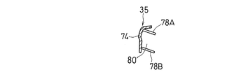
フレームカバー35の内側における前後方向中央部に、車体内側に突出する図7の係合突起68が形成されている。図8に示すように、フレームカバー35の前端に、前方に延設する前側支持部70が形成され、この前側支持部70に車幅方向を向いたボルト挿通孔112が形成されている。フレームカバー35の後端には、後方に延設する後側支持部72が形成され、この後側支持部72に車幅方向を向いたカバー貫通孔114が形成されている。フレームカバー35における吸気取入口55の後側には、図9(横断面図)に示すように、車体内側に開口したU字状の通路壁74によりエンジン吸気Iの導入路76が形成されている。さらに、導入路76の後部には、図10(横断面図)に示すように、通路壁74から車体内側に延びるガイド上壁78Aおよびガイド下壁78Bが突設されており、通路壁74とガイド上壁78Aとガイド下壁78Bとにより、吸気取入口55から取り入れたエンジン吸気Iを吸気ダクト59の入口59aに導入するガイド通路80が形成されている。
7 is formed at the center in the front-rear direction on the inner side of the
つぎに、フレームカバー35およびカウルインナ52の車体への取り付け構造について説明する。
図7のフレームカバー35の係合突起68を、ダンパのような弾性部材(図示せず)を介して、図4のメインフレーム1に設けた係合孔113に嵌合させる。フレームカバー35の前側支持部70のボルト挿通孔112およびメインフレーム1に設けた挿通孔(図示せず)に、ボルトのような締結部材116を挿通して、ナットで締め上げることでフレームカバー35の前部を車体に固定する。フレームカバー35の後側支持部72は、これを外側方から覆うピボットカバー17によりメインフレーム1に取り付けられている。すなわち、メインフレーム1の取付孔(図示せず)に取り付けたドーナツ形状のゴム製のダンパ118に、フレームカバー35の前記カバー貫通孔114を合わせ、ピボットカバー17に設けられた係止突起(図示せず)をダンパ118の中心孔に挿通することにより、ダンパ118を介してフレームカバー35をメインフレーム1に押し当てる。これにより、フレームカバー35の後部が、メインフレーム1とピボットカバー17とにより挟持されて車体に固定される。
Next, a structure for attaching the
The
図6に示す左右のカウルインナ52、52の第3の貫通孔104,104同士が重なり合うように係合片64,64同士を係合させ、重合された第3の貫通孔104の下方からリベットのような締結手段を挿通し、図4のアッパカウル36に設けた取付孔(図示せず)に締め付けることで、カウルインナ52をアッパカウル36に固定する。さらに、カウルインナ52における図6の第4の貫通孔106に、リベットのような締結手段を下方から挿通し、ヘッドランプユニット32に形成された取付孔(図示せず)に締め付けることで、カウルインナ52をヘッドランプユニット32に固定する。
The
カウルインナ52における第1および第2の貫通孔100,102と、図6に示す第5の貫通孔108とに、車体の内側からリベットのような締結手段を挿通し、図3のサイドカウル38に設けた取付孔(図示せず)に締め付けることで、カウルインナ52をサイドカウル38に固定する。このように、カウルインナ52は、ヘッドランプユニット32、アッパカウル36およびサイドカウル38を介して車体に支持される。
A fastening means such as a rivet is inserted from the inside of the vehicle body into the first and second through
つぎに、本実施形態の自動二輪車の導風構造について説明する。
自動二輪車の走行中、図3に示すように、フロントフェンダ15とアッパカウル36との間を通って、開口部54から走行風Aがカウリング30の内部に取り込まれる。カウリング30に取り込まれた走行風Aの大部分は、カウルインナ52の内面により案内されて、冷却空気Bとしてラジエータ18に送られ、ラジエータ18を冷却した後、図1の排風開口部50からカウリング30の外部に排出される。
Next, the wind guide structure of the motorcycle according to the present embodiment will be described.
During traveling of the motorcycle, as shown in FIG. 3, the traveling wind A is taken into the
カウリング30に取り込まれた走行風Aの一部は、図4のカウルインナ52のガイド部58に案内されて、エンジン吸気Iとしてフレームカバー35の吸気取入口55に送られ、吸気取入口55から導入路74を経て、吸気ダクト59からエアクリーナ20に供給される。エアクリーナ20に供給されたエンジン吸気Iは、エアクリーナ20で浄化されてエンジンEに送られる。
A part of the traveling wind A taken into the
このように、開口部54およびガイド部58を形成するカウルインナ52,52と、吸気取入口55を形成するフレームカバー35とにより、自動二輪車の導風構造が構成されている。
As described above, the
上記構成において、図2に示すように、カウリング30には単一の開口部54が設けられ、この開口部54を介してラジエータ18への冷却空気Bとエンジン吸気Iとを取り入れているので、エンジン吸気口55が露出しなくなり自動二輪車の外観が向上する。また、図4に示すように、開口部54内に案内された走行風Aの一部が、カウルインナ52の延長部分56に形成されたガイド部58により後方の吸気取入口55に導かれるので、吸気抵抗を抑制してエンジンEへの吸気を円滑に取り入れることができる。このように吸気取入口55まで外気が導風される結果、走行中の吸気温度が低くなって外気充填効率を向上させることができる。さらに、カウルインナ52を後方に延長させてガイド部58を設けるだけなので、構造も簡単である。
In the above configuration, as shown in FIG. 2, the
図5に示すように、ガイド部58は、後方に進むにつれて外側方に膨出する膨出部60を有しているので、図2に示す開口部54を小さく、特にその幅寸法W3を十分小さくして、自動二輪車の外観を一層向上させることができる。
As shown in FIG. 5, the
図4に示すように、メインフレーム1の2本のフレーム片1a,1bの間に、吸気取入口55が配置されているので、2本のフレーム片1a,1bを備えた独特の外観を有しながら、それらの間に吸気取入口55を形成することで、フレーム片1a,1bの間の空間を有効利用できる。しかも、ガイド部58により、2本のフレーム片1a,1bの高い位置にある吸気取入口55に、円滑に吸気を導入できる。
As shown in FIG. 4, since the
また、吸気取入口55は、両フレーム片1a,1bの間の隙間を覆うフレームカバー35により形成されているので、フレームカバー35により両フレーム片1a,1bの隙間が覆われるから、カウリング30を装着しないネイキッドタイプとしたときでも、見栄えがよい。
Further, since the
図3に示すように、フレームカバー35の吸気取入口55が、複数のスリット57により形成されているので、吸気取入口55への異物の侵入を防止できる。
As shown in FIG. 3, since the
図4に示すように、カウルインナ52の延長部分56の後縁56aが、側面視で、ラジエータ18の前面18aに沿って前傾しているので、ガイド部58が十分後方まで形成され、吸気取入口55に円滑に走行風Aを案内できる。カウルインナ52はラジエータ18の外側方を覆っていないので、カウルインナ52を通過した走行風Aはラジエータ18の両側方を通り、排風開口部50から外部に円滑に排出される。
As shown in FIG. 4, the
図6に示すように、カウルインナ52に、方向指示器34からの漏洩光がライダーに到達するのを阻止する遮光片66が設けられているので、走行中に方向指示器34からの漏洩光がライダーに到達するのを阻止して、ライダーの不快感を避けることができる。
As shown in FIG. 6, the cowl inner 52 is provided with a
以上のとおり、図面を参照しながら本発明の好適な実施形態を説明したが、本発明の趣旨を逸脱しない範囲内で、種々の追加、変更または削除が可能であり、そのようなものも本発明の範囲内に含まれる。例えば、上記実施形態では、カウルインナ52は、開口部54の内周面の一部分のみを形成していたが、内周面の全体を形成するようにしてもよい。したがって、そのようなものも本発明の範囲内に含まれる。
As described above, the preferred embodiment of the present invention has been described with reference to the drawings, but various additions, modifications, or deletions can be made without departing from the spirit of the present invention. Included within the scope of the invention. For example, in the above embodiment, the cowl inner 52 forms only a part of the inner peripheral surface of the
1 メインフレーム
1a、1b フレーム片
3 ヘッドパイプ
5 ロワブラケット
8 フロントフォーク
18 ラジエータ
30 カウリング
34 方向指示器
35 フレームカバー
52 カウルインナ
54 開口部
55 吸気取入口(取入口)
56 延長部分
57 スリット
58 ガイド部
60 膨出部
61 側壁
66 遮光片
A 走行風
B 冷却空気
E エンジン
FR 車体フレーム
I エンジン吸気
DESCRIPTION OF
56
Claims (7)
前記カウリングは、少なくともヘッドパイプの前方および前記ラジエータの外側方を覆っており、
前記開口部の内周面の少なくとも一部がカウルインナにより形成され、
前記ラジエータの上方に、前記開口部から流入した走行風の一部をエンジン吸気として取り入れる取入口が配置され、
前記カウルインナが後方に延長されて、少なくとも前記ヘッドパイプの下部とフロントフォークのロワブラケットとに外側方から対向する延長部分が形成され、
前記延長部分を含む前記カウルインナの側壁の内面に、前記取入口の前方下方に位置して、走行風を前記取入口に案内するガイド部が形成されている自動二輪車の導風構造。 A wind guide structure of a motorcycle that takes in cooling air and engine intake air to a radiator disposed in front of the engine from a single opening in a cowling attached to the front of the vehicle body,
The cowling covers at least the front of the head pipe and the outside of the radiator;
At least a part of the inner peripheral surface of the opening is formed by a cowl inner,
Above the radiator, an intake port for taking in part of the running wind flowing from the opening as engine intake air is disposed,
The cowl inner is extended rearward, and at least a lower portion of the head pipe and a lower bracket of the front fork are formed to extend from the outside,
A wind guide structure for a motorcycle, wherein a guide portion is formed on an inner surface of a side wall of the cowl inner including the extension portion, and is positioned in front of the intake port and guides a traveling wind to the intake port.
Priority Applications (4)
| Application Number | Priority Date | Filing Date | Title |
|---|---|---|---|
| JP2011219849A JP5921125B2 (en) | 2011-10-04 | 2011-10-04 | Motorcycle wind guide structure |
| CN201210366025.4A CN103029777B (en) | 2011-10-04 | 2012-09-28 | The air guide structure of motor bike |
| EP12187010.9A EP2578479B1 (en) | 2011-10-04 | 2012-10-02 | Air guiding structure for motorcycles |
| US13/644,457 US8881859B2 (en) | 2011-10-04 | 2012-10-04 | Air guiding structure for motorcycles |
Applications Claiming Priority (1)
| Application Number | Priority Date | Filing Date | Title |
|---|---|---|---|
| JP2011219849A JP5921125B2 (en) | 2011-10-04 | 2011-10-04 | Motorcycle wind guide structure |
Publications (2)
| Publication Number | Publication Date |
|---|---|
| JP2013078991A JP2013078991A (en) | 2013-05-02 |
| JP5921125B2 true JP5921125B2 (en) | 2016-05-24 |
Family
ID=46970127
Family Applications (1)
| Application Number | Title | Priority Date | Filing Date |
|---|---|---|---|
| JP2011219849A Expired - Fee Related JP5921125B2 (en) | 2011-10-04 | 2011-10-04 | Motorcycle wind guide structure |
Country Status (4)
| Country | Link |
|---|---|
| US (1) | US8881859B2 (en) |
| EP (1) | EP2578479B1 (en) |
| JP (1) | JP5921125B2 (en) |
| CN (1) | CN103029777B (en) |
Cited By (1)
| Publication number | Priority date | Publication date | Assignee | Title |
|---|---|---|---|---|
| US10351197B2 (en) | 2016-09-26 | 2019-07-16 | Kawasaki Jukogyo Kabushiki Kaisha | Front cowling for saddle-riding type vehicle |
Families Citing this family (22)
| Publication number | Priority date | Publication date | Assignee | Title |
|---|---|---|---|---|
| US8777291B2 (en) * | 2011-10-28 | 2014-07-15 | Roadawgz, Inc. | Motorcycle windscreen and fairing system using same |
| JP6071658B2 (en) * | 2013-03-08 | 2017-02-01 | 本田技研工業株式会社 | Undercarriage of the vehicle |
| US9096123B2 (en) * | 2013-06-07 | 2015-08-04 | Yamaha Hatsudoki Kabushiki Kaisha | Straddle-riding type vehicle |
| JP6140556B2 (en) * | 2013-07-10 | 2017-05-31 | 本田技研工業株式会社 | Motorcycle |
| JP6015720B2 (en) * | 2014-07-28 | 2016-10-26 | スズキ株式会社 | Motorcycle frame structure |
| EP3287350B1 (en) * | 2015-04-24 | 2019-09-11 | Honda Motor Co., Ltd. | Saddled-vehicle cowl structure |
| JP6492940B2 (en) | 2015-04-30 | 2019-04-03 | スズキ株式会社 | Saddle riding vehicle |
| DE102015213208B4 (en) | 2015-07-15 | 2024-07-18 | Bayerische Motoren Werke Aktiengesellschaft | Air deflector for a motorcycle |
| JP6346631B2 (en) * | 2016-03-24 | 2018-06-20 | 本田技研工業株式会社 | Front structure of saddle-ride type vehicle |
| JP6270895B2 (en) | 2016-03-24 | 2018-01-31 | 本田技研工業株式会社 | Front structure of saddle-ride type vehicle |
| DE102016208694A1 (en) | 2016-05-20 | 2017-11-23 | Bayerische Motoren Werke Aktiengesellschaft | Intake device for a motor vehicle |
| JP6848312B2 (en) * | 2016-09-30 | 2021-03-24 | スズキ株式会社 | Wind guide structure for saddle-mounted vehicles |
| DE102016220301B3 (en) * | 2016-10-18 | 2017-06-29 | Bayerische Motoren Werke Aktiengesellschaft | Motorcycle intake air duct for a motorcycle engine |
| JP6894696B2 (en) * | 2016-12-08 | 2021-06-30 | 川崎重工業株式会社 | Saddle-type vehicle |
| CN113847134B (en) * | 2017-03-09 | 2024-07-09 | Tvs电机股份有限公司 | Cooling system for internal combustion engine and method thereof |
| JP6489715B2 (en) * | 2017-03-27 | 2019-03-27 | 本田技研工業株式会社 | Body structure of saddle-ride type vehicle |
| DE112018005491B4 (en) | 2017-09-27 | 2022-09-15 | Honda Motor Co., Ltd. | EXTERIOR COVER COMPONENT STRUCTURE FOR SEMI-TRAILED VEHICLES |
| JP6997662B2 (en) * | 2018-03-28 | 2022-01-17 | 本田技研工業株式会社 | Intake structure of saddle-mounted vehicle |
| JP6806747B2 (en) * | 2018-09-28 | 2021-01-06 | 本田技研工業株式会社 | Cowl structure of saddle-riding vehicle |
| IT201800010889A1 (en) * | 2018-12-07 | 2020-06-07 | Piaggio & C Spa | MOTORCYCLE FRONT WITH IMPROVED COOLING AND RELATED MOTORCYCLE |
| JP7579125B2 (en) | 2020-12-07 | 2024-11-07 | カワサキモータース株式会社 | Motorcycles |
| JP2022104686A (en) * | 2020-12-29 | 2022-07-11 | ヤマハ発動機株式会社 | Saddle-riding type vehicle |
Family Cites Families (26)
| Publication number | Priority date | Publication date | Assignee | Title |
|---|---|---|---|---|
| JPS5960025U (en) * | 1982-10-15 | 1984-04-19 | 本田技研工業株式会社 | Intake devices for motorcycles, etc. |
| JPS6066594U (en) * | 1983-10-14 | 1985-05-11 | 本田技研工業株式会社 | Motorcycle fairing stay |
| JPS60127230U (en) * | 1984-02-06 | 1985-08-27 | 本田技研工業株式会社 | Intake devices for motorcycles, etc. |
| US5012883A (en) * | 1988-03-20 | 1991-05-07 | Honda Giken Kogyo Kabushiki Kaisha | Air duct device for a motorcycle |
| JP3183526B2 (en) * | 1991-03-20 | 2001-07-09 | 本田技研工業株式会社 | Radiator arrangement structure for motorcycle |
| JP3187888B2 (en) * | 1991-10-21 | 2001-07-16 | ヤマハ発動機株式会社 | Motorcycle |
| US5577570A (en) * | 1992-04-09 | 1996-11-26 | Yamaha Hatsudoki Kabushiki Kaisha | Wind introducing system for motorcycle |
| JPH07156848A (en) | 1993-12-08 | 1995-06-20 | Suzuki Motor Corp | Air cleaner device for motorcycle |
| JP3585486B2 (en) * | 1999-09-07 | 2004-11-04 | 本田技研工業株式会社 | Motorcycle intake structure |
| JP3532882B2 (en) * | 2001-05-01 | 2004-05-31 | ヤマハ発動機株式会社 | Motorcycle front cowl |
| JP3608549B2 (en) | 2001-12-25 | 2005-01-12 | スズキ株式会社 | Intake duct device for motorcycle |
| JP4340500B2 (en) * | 2003-09-09 | 2009-10-07 | 川崎重工業株式会社 | Intake device for motorcycle |
| JP4184923B2 (en) * | 2003-11-06 | 2008-11-19 | 本田技研工業株式会社 | Air cleaner structure |
| US6923489B2 (en) * | 2004-01-05 | 2005-08-02 | Timothy J. Keys | Motorcycle protective cover |
| JP4358011B2 (en) * | 2004-03-26 | 2009-11-04 | 本田技研工業株式会社 | Motorcycle cowl structure |
| JP2006213249A (en) * | 2005-02-04 | 2006-08-17 | Yamaha Motor Co Ltd | Motorcycle |
| JP4531613B2 (en) * | 2005-03-31 | 2010-08-25 | 本田技研工業株式会社 | Vehicle cowl structure |
| JP4584781B2 (en) * | 2005-06-15 | 2010-11-24 | 本田技研工業株式会社 | Cowling structure for motorcycles |
| JP4856485B2 (en) * | 2006-07-14 | 2012-01-18 | 本田技研工業株式会社 | Motorcycle cowling structure |
| JP2009107569A (en) * | 2007-10-31 | 2009-05-21 | Yamaha Motor Co Ltd | Cowl for motorcycle, and motorcycle |
| JP2009107568A (en) * | 2007-10-31 | 2009-05-21 | Yamaha Motor Co Ltd | Cowl for motor bicycle and motor bicycle |
| DE102008061123B4 (en) * | 2007-12-30 | 2017-06-01 | Honda Motor Co., Ltd. | motorcycle |
| CN102089199B (en) * | 2008-03-28 | 2013-05-22 | 雅马哈发动机株式会社 | Straddle riding-type vehicle |
| JP5566708B2 (en) * | 2010-01-27 | 2014-08-06 | 本田技研工業株式会社 | Cowling structure of saddle riding type vehicle |
| JP5624780B2 (en) * | 2010-03-23 | 2014-11-12 | 本田技研工業株式会社 | Air cleaner device |
| JP5656430B2 (en) * | 2010-03-23 | 2015-01-21 | 本田技研工業株式会社 | Air cleaner device |
-
2011
- 2011-10-04 JP JP2011219849A patent/JP5921125B2/en not_active Expired - Fee Related
-
2012
- 2012-09-28 CN CN201210366025.4A patent/CN103029777B/en not_active Expired - Fee Related
- 2012-10-02 EP EP12187010.9A patent/EP2578479B1/en not_active Not-in-force
- 2012-10-04 US US13/644,457 patent/US8881859B2/en not_active Expired - Fee Related
Cited By (1)
| Publication number | Priority date | Publication date | Assignee | Title |
|---|---|---|---|---|
| US10351197B2 (en) | 2016-09-26 | 2019-07-16 | Kawasaki Jukogyo Kabushiki Kaisha | Front cowling for saddle-riding type vehicle |
Also Published As
| Publication number | Publication date |
|---|---|
| US20130081896A1 (en) | 2013-04-04 |
| JP2013078991A (en) | 2013-05-02 |
| EP2578479A3 (en) | 2013-10-23 |
| CN103029777A (en) | 2013-04-10 |
| CN103029777B (en) | 2015-11-18 |
| US8881859B2 (en) | 2014-11-11 |
| EP2578479B1 (en) | 2014-05-14 |
| EP2578479A2 (en) | 2013-04-10 |
Similar Documents
| Publication | Publication Date | Title |
|---|---|---|
| JP5921125B2 (en) | Motorcycle wind guide structure | |
| US8631888B2 (en) | Cowling structure for saddle-ride type vehicle | |
| JP2007062643A (en) | Car body cooling structure of motorcycle and motorcycle | |
| JP5735894B2 (en) | Tank shroud structure | |
| JP6447383B2 (en) | Suction type vehicle intake structure | |
| JP4661472B2 (en) | Motorcycle cowling | |
| JP2006069404A (en) | Vehicle | |
| EP2161187A1 (en) | Motorcycle | |
| JP5820443B2 (en) | Scooter type vehicle | |
| WO2014185235A1 (en) | Air intake device for two-wheeled motor vehicle | |
| JP6055751B2 (en) | Intake device for saddle-ride type vehicles | |
| JP2019043204A (en) | Saddle-riding type vehicle | |
| JP5604960B2 (en) | Intake duct structure for motorcycles | |
| JP2011011570A (en) | Front cowling for motorcycle | |
| JP2022104686A (en) | Saddle-riding type vehicle | |
| JP2021041736A (en) | Regulator heat shield structure for saddle-mounted vehicles | |
| JP2009083679A (en) | Cowl structure of motorcycle | |
| JP2020059358A (en) | Saddle type vehicle | |
| JP2006213250A (en) | Motorcycle | |
| US20240262445A1 (en) | Cowling structure | |
| WO2022210876A1 (en) | Muffler apparatus | |
| JP6147534B2 (en) | Saddle riding vehicle | |
| JP2024131710A (en) | Saddle type vehicle | |
| JP2010179825A (en) | Radiator shroud structure of motorcycle | |
| JP2024110036A (en) | Cowling Structure |
Legal Events
| Date | Code | Title | Description |
|---|---|---|---|
| A621 | Written request for application examination |
Free format text: JAPANESE INTERMEDIATE CODE: A621 Effective date: 20140514 |
|
| A977 | Report on retrieval |
Free format text: JAPANESE INTERMEDIATE CODE: A971007 Effective date: 20150115 |
|
| A131 | Notification of reasons for refusal |
Free format text: JAPANESE INTERMEDIATE CODE: A131 Effective date: 20150303 |
|
| A521 | Request for written amendment filed |
Free format text: JAPANESE INTERMEDIATE CODE: A523 Effective date: 20150423 |
|
| A131 | Notification of reasons for refusal |
Free format text: JAPANESE INTERMEDIATE CODE: A131 Effective date: 20150929 |
|
| A521 | Request for written amendment filed |
Free format text: JAPANESE INTERMEDIATE CODE: A523 Effective date: 20151127 |
|
| TRDD | Decision of grant or rejection written | ||
| A01 | Written decision to grant a patent or to grant a registration (utility model) |
Free format text: JAPANESE INTERMEDIATE CODE: A01 Effective date: 20160405 |
|
| A61 | First payment of annual fees (during grant procedure) |
Free format text: JAPANESE INTERMEDIATE CODE: A61 Effective date: 20160412 |
|
| R150 | Certificate of patent or registration of utility model |
Ref document number: 5921125 Country of ref document: JP Free format text: JAPANESE INTERMEDIATE CODE: R150 |
|
| LAPS | Cancellation because of no payment of annual fees |