JP5909404B2 - Rotating electric machine - Google Patents
Rotating electric machine Download PDFInfo
- Publication number
- JP5909404B2 JP5909404B2 JP2012102197A JP2012102197A JP5909404B2 JP 5909404 B2 JP5909404 B2 JP 5909404B2 JP 2012102197 A JP2012102197 A JP 2012102197A JP 2012102197 A JP2012102197 A JP 2012102197A JP 5909404 B2 JP5909404 B2 JP 5909404B2
- Authority
- JP
- Japan
- Prior art keywords
- coil end
- support ring
- winding
- end portion
- intermediate plate
- Prior art date
- Legal status (The legal status is an assumption and is not a legal conclusion. Google has not performed a legal analysis and makes no representation as to the accuracy of the status listed.)
- Active
Links
- 238000004804 winding Methods 0.000 claims description 165
- 239000000463 material Substances 0.000 claims description 152
- 230000027455 binding Effects 0.000 claims description 120
- 238000009739 binding Methods 0.000 claims description 120
- 125000006850 spacer group Chemical group 0.000 claims description 31
- 239000004593 Epoxy Substances 0.000 claims description 5
- 239000011521 glass Substances 0.000 claims description 5
- 230000002093 peripheral effect Effects 0.000 claims description 3
- 229920005989 resin Polymers 0.000 description 11
- 239000011347 resin Substances 0.000 description 11
- 238000010586 diagram Methods 0.000 description 9
- 238000004458 analytical method Methods 0.000 description 8
- 239000003365 glass fiber Substances 0.000 description 8
- 230000000694 effects Effects 0.000 description 6
- 239000003822 epoxy resin Substances 0.000 description 6
- 230000004048 modification Effects 0.000 description 6
- 238000012986 modification Methods 0.000 description 6
- 229920000647 polyepoxide Polymers 0.000 description 6
- 229920001187 thermosetting polymer Polymers 0.000 description 6
- 229920006231 aramid fiber Polymers 0.000 description 5
- 238000004364 calculation method Methods 0.000 description 5
- 230000008901 benefit Effects 0.000 description 4
- 230000006866 deterioration Effects 0.000 description 4
- 238000010438 heat treatment Methods 0.000 description 4
- 238000009413 insulation Methods 0.000 description 3
- 238000005728 strengthening Methods 0.000 description 3
- 239000000853 adhesive Substances 0.000 description 2
- 230000001070 adhesive effect Effects 0.000 description 2
- 239000004020 conductor Substances 0.000 description 2
- 238000010292 electrical insulation Methods 0.000 description 2
- 230000005284 excitation Effects 0.000 description 2
- 239000000835 fiber Substances 0.000 description 2
- 210000004907 gland Anatomy 0.000 description 2
- 238000004519 manufacturing process Methods 0.000 description 2
- 238000000034 method Methods 0.000 description 2
- 230000009466 transformation Effects 0.000 description 2
- 239000011230 binding agent Substances 0.000 description 1
- LNEPOXFFQSENCJ-UHFFFAOYSA-N haloperidol Chemical compound C1CC(O)(C=2C=CC(Cl)=CC=2)CCN1CCCC(=O)C1=CC=C(F)C=C1 LNEPOXFFQSENCJ-UHFFFAOYSA-N 0.000 description 1
- 239000012783 reinforcing fiber Substances 0.000 description 1
Images


Landscapes
- Insulation, Fastening Of Motor, Generator Windings (AREA)
Description
本発明は発電機や電動機のような回転電機に関り、特に固定子コイルエンド部巻線と支持リングの固定部の締結剛性を向上した回転電機に関するものである。 The present invention relates to a rotating electrical machine such as a generator or an electric motor, and more particularly to a rotating electrical machine having improved fastening rigidity between a stator coil end winding and a fixing portion of a support ring.
一般的にタービン発電機のような回転電機を運転する場合、回転電機の固定子コイルエンド部巻線は運転時に作用する電磁加振力によって振動する。このコイルエンド部巻線が振動するとコイルエンド部巻線に応力が繰り返し作用してコイルエンド部巻線に疲労が生じ好ましいものではない。 In general, when operating a rotating electrical machine such as a turbine generator, a stator coil end winding of the rotating electrical machine vibrates due to an electromagnetic excitation force acting during operation. When the coil end portion winding vibrates, stress is repeatedly applied to the coil end portion winding, and fatigue is generated in the coil end portion winding.
この電磁振動によるコイルエンド部巻線の振動を抑えるために、コイルエンド部巻線は固定子鉄心の両端に配置された支持リングに繊維強化樹脂のような材料で作られた紐状の結束材によって縛り付けられ、固定されている。 In order to suppress the vibration of the coil end part winding due to this electromagnetic vibration, the coil end part winding is a string-like binding material made of a material such as a fiber reinforced resin on support rings arranged at both ends of the stator core. Bound and fixed by.
例えば、特開2002−27696号公報(特許文献1)の図14にはこのような固定構造が提案されている。即ち、コイルエンド部巻線の周りに強化繊維と樹脂からなる円環状の支持リングを配置し、コイルエンド部巻線を支持リングで支持する構造となっている。このコイルエンド部巻線と支持リングは、特許文献1の図18及び図19に示されるように、コイルエンド部巻線と支持リングの間にスペーサを挟んだ状態で、上記の結束材によって両者が縛り付けられて締結、固定されている。
For example, FIG. 14 of Japanese Patent Laid-Open No. 2002-27696 (Patent Document 1) proposes such a fixing structure. That is, an annular support ring made of reinforcing fiber and resin is disposed around the coil end portion winding, and the coil end portion winding is supported by the support ring. As shown in FIGS. 18 and 19 of
特許文献1では、更にコイルエンド部巻線が支持リングの周方向にずれることを防止するために、支持リングの表面にコイルエンド部巻線の幅とコイルエンド部巻線同士の間隔に合わせて繊維強化樹脂による突起部を設ける構造が提案されている。つまり、結束材であるプリプレグ材を支持リングの表面に貼り付ける、または支持リングに螺旋状に巻きつけることで突起部を形成し、この突起部をコイルエンド部巻線と接触させることでコイルエンド部巻線の支持リングへの固定力を強化してコイルエンド部巻線の締結剛性を向上している。
In
また、固定子のコイルエンド部巻線の剛性をより強固にする構造として、例えば米国特許第3437859号明細書(特許文献2)の図9には、隣り合うコイルエンド部巻線同士の間にスペーサを挟み、コイルエンド部巻線同士を結束材で締結する構造が開示されている。特許文献2ではさらに、巻線同士をつなぐ結束材(Wrapping8)の上に別の結束材(Frapping9)を巻きつけることで結束材(Wrapping8)に張力を加え、巻線同士間の締結の剛性を増す方法が開示されている。
Further, as a structure for further strengthening the rigidity of the coil end portion winding of the stator, for example, in FIG. 9 of US Pat. No. 3,347,859 (Patent Document 2), there is a gap between adjacent coil end portion windings. A structure is disclosed in which the coil end portion windings are fastened with a binding material with a spacer interposed therebetween. Further, in
タービン発電機のような大型の回転電機の製造工程では、結束材の縛り付けによる締結は全て手作業で行われるため、多大な時間とコストがかかるということが製造上の課題であった。特に大型の回転電機ではコイルエンド部巻線と支持リングの締結箇所が500箇所を超えるものがあり、固定子のコイルエンド部巻線の支持剛性を保ちながら、その締結箇所の
総数を減らすことが要請されている。
In the manufacturing process of a large-sized rotating electrical machine such as a turbine generator, since fastening by binding of binding materials is all performed manually, it is a manufacturing problem that much time and cost are required. In particular, in large rotating electrical machines, the number of fastening points between the coil end part winding and the support ring exceeds 500, and the total number of fastening parts can be reduced while maintaining the support rigidity of the coil end part winding of the stator. It has been requested.
特許文献1に開示されている構成によれば、支持リングの表面に設けた突起部によりコイルエンド部巻線の周方向へのずれを防ぐことができる。しかしながら、この突起部を設けるためには、支持リングに結束材を巻きつける必要があり、従来よりも結束材を巻く作業工数が増えていた。
According to the configuration disclosed in
また、実際のコイルエンド部巻線同士の間隔にはいくらかのばらつきがあるため、支持リングとコイルエンド部巻線を結束材で締結する際に、支持リングの表面に予め設けておいた突起部の間隔が、コイルエンド部巻線の間隔と一致せず、突起部とコイルエンド部巻線が接触しない箇所が現れる可能性がある。 Also, since there is some variation in the spacing between the actual coil end part windings, when the support ring and coil end part winding are fastened with a binding material, the protrusions provided in advance on the surface of the support ring There is a possibility that a portion where the protrusion does not come into contact with the coil end portion winding does not coincide with the interval between the coil end portion windings.
すなわちこの構成では、コイルエンド部巻線と支持リングの間の固定力が必ずしも強化されるとは限らず、したがって固定力の強化を見越して結束材による締結箇所の総数を減らすという設計は困難である。 That is, in this configuration, the fixing force between the coil end portion winding and the support ring is not necessarily strengthened, and therefore, it is difficult to design to reduce the total number of fastening points by the binding material in anticipation of the strengthening of the fixing force. is there.
また、特許文献2に開示されている構成では、コイルエンド部巻線同士をつなぐ結束材に張力をかけるため、さらに別の結束材を巻く必要があり、結束材を巻く作業工数が2倍に増えて、更に作業時間とコストの増加を招くという課題が生じる。
本発明の目的は、コイルエンド部巻線と支持リングの締結剛性を向上して、結束材の縛り付けの作業工数を低減できるコイルエンド部巻線と支持リングの固定構造を備えた回転電機を提供することにある。
Moreover, in the structure currently disclosed by
An object of the present invention is to provide a rotating electrical machine having a coil end portion winding and support ring fixing structure that can improve the fastening rigidity of the coil end portion winding and the support ring and reduce the work man-hours for binding the binding material. There is to do.
本発明の特徴は、固定子鉄心の軸方向端部から張出した固定子コイルエンド部巻線と、コイルエンド部巻線を環状に保持する支持リングを備え、コイルエンド部巻線と支持リングの間が結束材によって締結固定され、コイルエンド部巻線、或いは支持リングと結束材の間には中間板材が配置されており、中間板材の上から結束材が巻かれていると共に、コイルエンド部巻線の周方向の側面に中間板材が配置され、中間板材を介して結束材によってコイルエンド部巻線と支持リングが締結、固定され、中間板材は支持リングに対向する側とは反対側に凹んだ凹部を有し、この凹部にコイルエンド部巻線が収容されている、ところにある。A feature of the present invention is that it includes a stator coil end winding that protrudes from an axial end of the stator core, and a support ring that holds the coil end winding in an annular shape. The intermediate plate is arranged between the coil end portion winding or the support ring and the binding material, and the binding material is wound on the intermediate plate, and the coil end portion An intermediate plate is arranged on the side surface in the circumferential direction of the winding, and the coil end part winding and the support ring are fastened and fixed by the binding material via the intermediate plate, and the intermediate plate is opposite to the side facing the support ring. There is a recessed portion, and the coil end portion winding is accommodated in the recessed portion.
本発明の他の特徴は、固定子鉄心の軸方向端部から張出した固定子コイルエンド部巻線と、コイルエンド部巻線を環状に保持する支持リングを備え、コイルエンド部巻線と支持リングの間が結束材によって締結固定され、コイルエンド部巻線、或いは支持リングと結束材の間には中間板材が配置されており、中間板材の上から結束材が巻かれていると共に、支持リングの軸方向の側面に中間板材が配置され、中間板材を介して結束材よってコイルエンド部巻線と支持リングが締結、固定されている、ところにある。Another feature of the present invention includes a stator coil end winding projecting from the axial end of the stator core, and a support ring that holds the coil end winding in an annular shape, and supports the coil end winding. The ring is fastened and fixed by a binding material, and an intermediate plate is arranged between the coil end winding or the support ring and the binding material, and the binding material is wound on the intermediate plate and supported. The intermediate plate material is disposed on the side surface in the axial direction of the ring, and the coil end portion winding and the support ring are fastened and fixed by the binding material via the intermediate plate material.
本発明の更に他の特徴は、固定子鉄心の軸方向端部から張出した固定子コイルエンド部巻線と、コイルエンド部巻線を環状に保持する支持リングを備え、コイルエンド部巻線と支持リングの間が結束材によって締結固定され、コイルエンド部巻線、或いは支持リングと結束材の間には中間板材が配置されており、中間板材の上から結束材が巻かれていると共に、支持リングの軸方向の側面に中間板材と同様の機能を有する拡大部を一体的に形成し、拡大部を介して結束材よってコイルエンド部巻線と支持リングが締結、固定されている、ところにある。Still another feature of the present invention includes a stator coil end winding that protrudes from an axial end of the stator core, and a support ring that holds the coil end winding in an annular shape, and a coil end winding. Between the support rings are fastened and fixed by a binding material, an intermediate plate material is arranged between the coil end part winding or the support ring and the binding material, and the binding material is wound on the intermediate plate material, An enlarged portion having the same function as that of the intermediate plate is integrally formed on the side surface in the axial direction of the support ring, and the coil end portion winding and the support ring are fastened and fixed by a binding material through the enlarged portion. It is in.
本発明の更に他の特徴は、固定子鉄心の軸方向端部から張出した固定子コイルエンド部巻線と、コイルエンド部巻線を環状に保持する支持リングを備え、コイルエンド部巻線と支持リングの間が結束材によって締結固定され、コイルエンド部巻線、或いは支持リングと結束材の間には中間板材が配置されており、中間板材の上から結束材が巻かれていると共に、結束材は支持リングの外周面で襷掛けに交差して結束されている、ところにある。 Still another feature of the present invention includes a stator coil end winding that protrudes from an axial end of the stator core, and a support ring that holds the coil end winding in an annular shape, and a coil end winding. Between the support rings are fastened and fixed by a binding material, an intermediate plate material is arranged between the coil end part winding or the support ring and the binding material, and the binding material is wound on the intermediate plate material, The binding material is located at the outer peripheral surface of the support ring so as to cross the hook.
本発明によれば、コイルエンド部巻線、或いは支持リングを締結するために用いられる結束材の間隔が中間板材によって広くなるため、締結部の締結剛性を増加させることができる。この剛性の増加分は、回転電機の設計段階で予め計算することができるため、コイルエンド部巻線の締結剛性を所定値に保ちながら、結束材による締結箇所の総数を減らすことができる。 According to the present invention, since the interval between the binding materials used for fastening the coil end part winding or the support ring is widened by the intermediate plate material, the fastening rigidity of the fastening part can be increased. Since this increase in rigidity can be calculated in advance at the design stage of the rotating electrical machine, the total number of fastening points by the binding material can be reduced while keeping the fastening rigidity of the coil end portion winding at a predetermined value.
以下、本発明の実施の形態を図面に基づいて詳細に説明するが、同一の参照番号は同一の構成要素、或いは類似の機能を備えた構成要素を示している。 Hereinafter, embodiments of the present invention will be described in detail with reference to the drawings. The same reference numerals indicate the same components or components having similar functions.
本発明の第1の実施形態であるコイルエンド部巻線と支持リングの締結構造について、図1を参照しながら説明する。尚、固定子のコイルエンド部巻線と支持リングの具体的な構成等は特許文献1の図2に示されている通りであり、固定子コアの端部にエンドプレートを介してリング支えが固定されており、さらにこのリング支えによって支持リング(ここでは3本)が順次間隔を空けて固定支持され、この各支持リングに多数のコイルエンド部巻線が順番に結束材によって縛り付けられて締結されている。
The fastening structure of the coil end portion winding and the support ring according to the first embodiment of the present invention will be described with reference to FIG. The specific configuration of the coil end portion winding and the support ring of the stator is as shown in FIG. 2 of
図1はこの支持リングと一本のコイルエンド部巻線の締結部を拡大して模式的に示しており、コイルエンド部巻線50と支持リング10の締結部を表す図である。図1に示すように、固定子巻線は導体2と絶縁層1から構成されており、固定子コイルエンド部巻線50と支持リング10の間にはスペーサ4が配置され、更にコイルエンド部巻線50の側面には中間板材20が配置された状態で、コイルエンド部巻線50と支持リング10が結束材3によって縛り付けられ、締結、固定されている。ここで中間板材20はある程度の固さを備えた材料で作られている。
FIG. 1 schematically shows an enlarged fastening portion of the support ring and one coil end portion winding, and shows a fastening portion of the coil end portion winding 50 and the
スペーサ4はガラス繊維またはアラミド繊維などに未硬化の熱硬化性樹脂(エポキシ樹脂など)を含浸させたプリプレグフェルトであり、コイルエンド部巻線50と支持リング10を縛り付けて組み立てる際には、スペーサ4をコイルエンド部巻線50と支持リング10の間に圧縮して挿入し、その後、加熱して硬化させることで、スペーサ4とコイルエンド部巻線50の間およびスペーサ4と支持リング10の間が接着、固定される。エポキシ樹脂は接着力が強く、かつ耐熱性に優れているので、この種の材料には好適である。
The
結束材3は紐状のガラス繊維に熱硬化性樹脂を含浸したプリプレグ材料であり、上述したスペーサ4と同じく加熱によって硬化し、結束材3と中間板材20の間、結束材3とコイルエンド部巻線50の間、および結束材3と支持リング10の間が接着、固定される。
The
中間板材20はコイルエンド部巻線50と支持リング10の間の締結剛性を上げるために設けられたものであり、中間板材20とコイルエンド部巻線50の間は接着されている。中間板材20の材料としては電気絶縁性、耐熱性、機械強度に優れたガラスエポキシ積層板が好適である。
The
図1において、従来提案されていた支持リング10とコイルエンド部巻線50の結束材3による縛り付け締結は中間板材20が備えられていない構造であったのに対し、本実施例では中間板材20を介して支持リング10とコイルエンド部巻線50を結束材3で縛り付けして締結固定するようにした点で異なっている。本実施例においてはこの中間板材20の追加によって締結剛性が著しく向上するようになったもので、次に、本実施例の作用、効果について説明する。
In FIG. 1, the
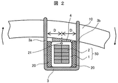
回転電機のコイルエンド部巻線50は運転時に作用する電磁加振力によって振動する。この振動によって生じる変形に関して、特にコイルエンド部巻線50と支持リング10の間の相対的な回転変形に着目して、その変形の様子を図示すると図2のようになる。ここではコイルエンド部巻線50から見た支持リング10の時計回りの回転変形の状態を図示している。支持リング10が図2のごとく時計回りに回転変形すると、図2の左側の結束材3aには引張ひずみ+εが生じ、右側の結束材3bには圧縮ひずみ−εが生じる。尚、結束材3a及び結束材3bは一本の紐であるが、左右に作用する荷重を説明するため、便宜的に結束材3a及び結束材3bと表記している。
The coil end portion winding 50 of the rotating electrical machine vibrates due to an electromagnetic excitation force acting during operation. Regarding the deformation caused by this vibration, focusing on the relative rotational deformation between the coil end portion winding 50 and the
このとき結束材3に発生する反力Fは結束材3の断面積A、弾性定数E、ひずみεの3つの積で決まり、以下の(1)式で表すことができる。
F=A×E×ε…(1)
更に、図2に示す支持リング10の回転中心21から図面上で左右の結束材3a、3bまでの距離をDとすると、図2の変形に対する結束材3の回転反力Mは2本の結束材3a、3bの回転反力をその回転方向を考慮して足し合わせて以下の(2)式で表すことができる。
M=2F×D=2A×E×ε×D…(2)
ここで、結束材3に発生するひずみは回転中心21から結束材3a、3bまでの距離Dが遠いほど大きくなる。このひずみは距離Dに比例するため、ひずみと距離の関係は定数αを用いて以下の(3)式で表すことができる。
ε=α×D…(3)
ここまでの式をまとめると、最終的に結束材3の回転反力Mは以下の(4)式となり、回転反力Mは回転中心21から結束材3までの距離Dの2乗に比例して増加することがわかる。
M=2A×E×α×D2…(4)
回転反力Mが増加するということは、回転変形に対する抵抗力が大きいということであり、すなわち、この締結部の剛性が大きいことを意味している。つまり回転中心21から結束材3a、3bまでの距離Dを大きくすることで、締結部の締結剛性を効果的に増加させることができる。そこで本実施例では、この距離Dを大きくするために中間板材20を使用している。
At this time, the reaction force F generated in the
F = A × E × ε (1)
Furthermore, when the distance from the
M = 2F × D = 2A × E × ε × D (2)
Here, the distortion generated in the
ε = α × D (3)
Summarizing the formulas so far, the rotational reaction force M of the
M = 2A × E × α × D 2 (4)
An increase in the rotational reaction force M means that the resistance force against rotational deformation is large, that is, the rigidity of the fastening portion is large. That is, by increasing the distance D from the
本実施例では、上述したように結束材3とコイルエンド部巻線50の間に中間板材20を挟んでいるため、中間板材20がない従来の構造と比較して回転中心21から結束材3a、3bまでの距離をDが大きくなり、締結部の締結剛性を従来よりも増加させることができる。
In this embodiment, since the
更に、この剛性の増加分は中間板材20の厚みによって決まるため、回転電機の設計段階で締結部の剛性の増加分を予め計算することができる。このため、固定子コイルエンド部巻線50の締結剛性を従来構造と同程度になるように保つ設計とすると、支持リング10とコイルエンド部巻線50の間の結束材3による締結箇所の総数を減らすことが可能となる。つまり、結束材3の縛り付け数が少なくなるので、その分だけ結束材3を縛り付けするのに必要な作業時間と作業コストを削減することが可能となる。
Furthermore, since the increase in rigidity is determined by the thickness of the
また、本実施例においては結束材3が中間板材20を介してコイルエンド部巻線50と接触するので、コイルエンド部巻腺50の絶縁層1の角部と直接接触しない構成となって、従来の構造と比較して絶縁層1の角部に発生する応力が小さくなり、絶縁層1の絶縁信頼性を向上させることができる。
Further, in the present embodiment, the binding
以上に説明した構造は実施形態の一例であって、本発明はこれに限定されることはなく、例えば、図3に示したように中間板材20の角に丸み20Aを設ける構造としてもよい。図1に示す構造では中間板材20の角が直角であるため、結束材3が中間板材20の角部によって傷つけられる可能性があるので結束材3のこの部分での劣化が早まる恐れがあったが、図3に示すように中間板材20の角に丸み20Aを設けるようにすると結束材3の劣化を抑制することができる。
The structure described above is an example of the embodiment, and the present invention is not limited to this. For example, as shown in FIG. 3, the
また、図4に示すように支持リング10に対向する側と反対側に凹型の中間板材20を設け、この中間板材20の内側にスペーサ22を介装し、このスペーサ22内にコイルエンド部巻線50を収納する構造としてもよい。
Also, as shown in FIG. 4, a concave
スペーサ22はスペーサ4と同様にガラス繊維またはアラミド繊維などに未硬化の熱硬化性樹脂(エポキシ樹脂など)を含浸させたプリプレグフェルトであり、加熱して硬化させることができる。したがって、加熱硬化する前のスペーサ22は柔かく容易に変形するため、コイルエンド部巻線50と中間板材20の間の隙間をスペーサ22で埋めることができ、コイルエンド部巻線50と中間板材20の間を良好に接着できるという利点がある。
The
次に本発明の第2の実施形態であるコイルエンド部巻線と支持リングの締結構造について、図5を参照しながら説明する。第1の実施形態が結束材3とコイルエンド部巻線50の間に中間板材20を介装しているのに対し、第2の実施形態では結束材3と支持リング10の間に中間板材30を介装している点で異なっている。
Next, the fastening structure of the coil end part winding and the support ring according to the second embodiment of the present invention will be described with reference to FIG. In the first embodiment, the
図5はコイルエンド部巻線50と支持リング10の締結部を表す斜視図であり、コイルエンド部巻線50と支持リング10の間にはスペーサ4が配置され、更に支持リング10の側面には中間板材30が配置された状態で、コイルエンド部巻線50と支持リング10が結束材3で縛り付けられて締結固定されている。結束材3は支持リング10の外周で襷掛けして交差するように締結されている。
FIG. 5 is a perspective view showing a fastening portion between the coil end portion winding 50 and the
ここで、スペーサ4はガラス繊維またはアラミド繊維などに未硬化の熱硬化性樹脂(エポキシ樹脂など)を含浸させたプリプレグフェルトであり、コイルエンド部巻線50と支持リング10を縛り付ける組み立ての際には、スペーサ4をコイルエンド部巻線50と支持リング10の間に圧縮して挿入し、その後、加熱して硬化させることで、スペーサ4とコイルエンド部巻線50の間およびスペーサ4と支持リング10の間が接着固定される。
Here, the
結束材3は紐状のガラス繊維に樹脂を含浸したプリプレグ材料であり、第1の実施形態と同様にスペーサ4と同じく加熱によって硬化し、結束材3と中間板材30の間、結束材3とコイルエンド部巻線50の間、および結束材3と支持リング10の間が接着、固定される。
The
支持リング10の軸方向の両側面に中間板材30が配置されており、この中間部材30によって結束材3の間隔が大きくされて締結の剛性を上げるようになっている。中間板材30と支持リング10の間は接着、固定されており、中間板材30の材料としては第1の実施形態と同様に電気絶縁性、耐熱性、機械強度に優れたガラスエポキシ積層板が好適である。
この実施形態では、結束材3b、及び結束材3b′の、コイルエンド部巻線50の長さ方向の間隔Wが中間板材30を配置することで広くなっている。このため第1の実施形態で詳細に説明したとおり、コイルエンド部巻線50と支持リング10の間の締結部の剛性を増加させることができる。
In this embodiment, the interval W in the length direction of the coil end portion winding 50 between the
更に、この剛性の増加分は中間板材30の厚みによって決まるため、回転電機の設計段階で締結部の剛性の増加分を予め計算することができる。このため、固定子のコイルエンド部巻線50の締結剛性を従来構造と同程度になるように保つ設計とすると、支持リング10とコイルエンド部巻線50の間の結束材3による締結箇所の総数を減らすことが可能となる。つまり、結束材3の縛り付け数が少なくなるので、その分だけ結束材3を縛り付けするのに必要な作業時間と作業コストを削減することが可能となる。
Furthermore, since the increase in rigidity is determined by the thickness of the
以上に説明した構造は実施形態の一例であって、本発明はこれに限定されることはなく、例えば、図6に示すように支持リング10の両側面に凸部11を一体的に形成して支持リング10の軸方向の幅を部分的に太くすることで中間板材30と同じ機能を持たせることができ、結束材3の間隔Wを広げることができる。
The structure described above is an example of the embodiment, and the present invention is not limited to this. For example, as shown in FIG. 6,
このような実施構造であれば中間板材30を支持リング10に貼り付ける必要がなく、作業性が改善されるという利点がある。また、支持リング10の凸部11はスペーサ4によってコイルエンド部巻線50と接着されるため、コイルエンド部巻線50と支持リング10の間の接着の幅(コイルエンド部巻線50の長さ方向の接着の幅)が図5に示す実施例に比べて広くなり、スペーサ4による接着の剛性が増加する。これによってコイルエンド部巻線50をより強固に支持することができるという利点もある。
With such an implementation structure, there is no need to affix the
次に実施例1および実施例2で説明した構造の効果を有限要素法による数値計算で検証した結果について、図7乃至図12を参照しながら説明する。 Next, the results of verifying the effects of the structures described in the first and second embodiments by numerical calculation using the finite element method will be described with reference to FIGS.
図7及び図8は解析に用いたモデルの形状を表す図である。図7は従来のコイルエンド部巻線50と支持リング10の締結構造を表しており、コイルエンド部巻線50と支持リング10は正方形断面の角棒でモデル化している。そして、コイルエンド部巻線50と支持リング10の断面寸法は等しいとし、正方形断面の辺の長さは50mmとした。
7 and 8 are diagrams showing the shape of the model used for the analysis. FIG. 7 shows a conventional fastening structure of the coil end portion winding 50 and the
図8は実施例1および実施例2で説明した構造を図7のモデルに適用したものであり、コイルエンド部巻線50と支持リング10の寸法は図7のモデルと同一である。
FIG. 8 shows a structure in which the structure described in the first and second embodiments is applied to the model of FIG. 7, and the dimensions of the coil end portion winding 50 and the
このモデルではコイルエンド部巻線50と結束材3の間、及び支持リング10と結束材3の間に同じ板厚の中間板材20、及び中間板材30が配置されている。中間板材20、及び中間板材30はガラスエポキシ積層板とし、その厚みは10mmと15mmの2種類を使用した。解析の境界条件は自由支持とし、材料物性値には測定値および、文献値を使用して固有振動数解析を行った。
In this model, the
この解析で評価した振動モードの変形図を図9および図10に示している。この図では変形の特徴をわかりやすくするため、コイルエンド部巻線50と支持リング10の2つの材料だけの変形を模式的に示している。図中の実線は変形後の形状を示し、点線は変形前の形状を示している。
FIG. 9 and FIG. 10 show deformation views of vibration modes evaluated by this analysis. In this figure, only the two materials of the coil end portion winding 50 and the
図9はコイルエンド部巻線50と支持リング10が図中のxy平面内でそれぞれ逆方向に回転振動する振動モードであり、この変形では結束材3(図示せず)がねじられるため、以後このモードをねじりモードと称する。
FIG. 9 shows a vibration mode in which the coil end portion winding 50 and the
図10はコイルエンド部巻線50と支持リング10が図中のyz平面内でそれぞれ逆方向に回転振動する振動モードであり、以後このモードを回転モードと称する。ねじりモードと回転モードの固有振動数の計算結果を図11に示している。
FIG. 10 shows a vibration mode in which the coil end portion winding 50 and the
図11の横軸は板材の厚みを角棒(コイルエンド部巻線50と結束材3をモデル化したもの)の辺の長さで割ったものであり、横軸の値が「0」のときの計算値は図7の従来構造の計算結果である。この図から、横軸の値が大きくなるほど、つまり中間板材の板厚が増えるほど固有振動数が大きくなっていることがわかる。 The horizontal axis in FIG. 11 is obtained by dividing the thickness of the plate material by the length of the side of the square bar (modeled coil end portion winding 50 and the binding material 3), and the value of the horizontal axis is “0”. The calculated value at that time is the calculation result of the conventional structure of FIG. From this figure, it can be seen that the natural frequency increases as the value on the horizontal axis increases, that is, as the thickness of the intermediate plate increases.
一般的に剛性は固有振動数の2乗に比例することが知られているため、図11で得られた固有振動数の値を2乗し、従来構造の値を基準として締結部の剛性の比を計算すると図12のようになる。この図から中間板材の厚みを角棒の辺の長さの0.3倍に設定することで、ねじりモードの締結部の剛性が70%、回転モードの締結部の剛性が60%増加することがわかる。 Since it is generally known that the rigidity is proportional to the square of the natural frequency, the value of the natural frequency obtained in FIG. 11 is squared, and the rigidity of the fastening portion is determined based on the value of the conventional structure. The ratio is calculated as shown in FIG. From this figure, setting the thickness of the intermediate plate to 0.3 times the length of the side of the square bar increases the rigidity of the torsion mode fastening part by 70% and the rotational mode fastening part by 60%. I understand.
つまり図8の構造をコイルエンド部巻線50と支持リング10の間の締結部に採用し、中間板材20,30の厚みをコイルエンド部巻線50または支持リング10の幅の30%にすることで、この結束材3による締結箇所の総数を35%減らしたとしても、固定子のコイルエンド部巻線50と支持リング10の締結剛性を従来と同程度に保つことができることを意味している。
That is, the structure of FIG. 8 is employed in the fastening portion between the coil end portion winding 50 and the
次に本発明の第3の実施形態である隣り合うコイルエンド部巻線の締結構造について、図13を参照しながら説明する。第1の実施形態が結束材3とコイルエンド部巻線50の間に中間板材20を介装しているのに対し、第3の実施形態では隣り合うコイルエンド部巻線50を結束材3によって締結、固定する点で異なっている。
Next, a fastening structure of adjacent coil end part windings, which is a third embodiment of the present invention, will be described with reference to FIG. In the first embodiment, the
本発明の第3の実施形態の締結構造について図13を参照しながら説明する。図13は隣接するコイルエンド部巻線50間の締結部の構造を示す図であり、2つのコイルエンド部巻線50の間にはブロック材5をフェルト6で挟んだものが挿入されている。このブロック材5とフェルト6は相互のコイルエンド部巻線50が近づきすぎないようにする機能を有している。
A fastening structure according to a third embodiment of the present invention will be described with reference to FIG. FIG. 13 is a view showing a structure of a fastening portion between adjacent coil
フェルト6はガラス繊維またはアラミド繊維などに未硬化の熱硬化性樹脂(エポキシ樹脂など)を含浸させたプリプレグフェルトであり、このフェルト6とコイルエンド部巻線50の間、及びフェルト6とブロック材5の間は接着されている。
The
更に、コイルエンド部巻線50の上下には中間板材20が接着されており、この中間板材20の上から、ガラス繊維に樹脂を含浸した結束材3が巻かれて、隣り合うコイルエンド部巻線50同士を相互に締結、固定している。中間板材20およびブロック材5の材料としては電気絶縁性、耐熱性、機械強度に優れたガラスエポキシ積層板が好適である。
Further, the
そして、図13に示したコイルエンド部巻線50の上下に設けた中間部材20によって結束材3の間隔Hが従来よりも広くなるため、実施例1で説明したように締結部の締結剛性を従来よりも増加させることができる。
And since the space | interval H of the
更に、この剛性の増加分は中間板材20の厚みによって決まるため、回転電機の設計段階で締結部の剛性の増加分を予め計算することができる。このため、固定子の隣り合うコイルエンド部巻線50の締結剛性を従来構造と同程度になるように保つ設計とすると、コイルエンド部巻線50の間の結束材3による締結箇所の総数を減らすことが可能となる。つまり、結束材3の縛り付け数が少なくなるので、その分だけ結束材3を縛り付けするのに必要な作業時間と作業コストを削減することが可能となる。
Furthermore, since the increase in rigidity is determined by the thickness of the
また、この第3の実施形態によれば結束材3がコイルエンド巻腺50の絶縁層1の角部と直接接触しないので、従来と比較して絶縁層1の角部に発生する応力が小さくなり、絶縁層1の絶縁信頼性を向上させることができる。
In addition, according to the third embodiment, the binding
以上に説明した構造は実施形態の一例であって、本発明はこれに限定されることはなく、例えば、図14に示すように中間板材20の角に丸み20Aを設ける構造としてもよい。図13に示す構造では中間板材20の角が直角であるため、結束材3が中間板材20の角部によって傷つけられる可能性があるので結束材3のこの部分での劣化が早まる恐れがあったが、図14に示すように中間板材20の角に丸み20Aを設けるようにすると結束材3の劣化を抑制することができる。
The structure described above is an example of the embodiment, and the present invention is not limited to this. For example, as shown in FIG. In the structure shown in FIG. 13, since the corners of the
また、図15に示すように、コイルエンド巻腺50のフェルト6と接着していない側の側面に、凹型の中間板材20を設け、この中間板材20の内側にスペーサ22を介装し、このスペーサ22内にコイルエンド部巻線50を収納する構造としてもよい。
Further, as shown in FIG. 15, a concave
スペーサ22はスペーサ6と同様にガラス繊維またはアラミド繊維などに未硬化の熱硬化性樹脂(エポキシ樹脂など)を含浸させたプリプレグフェルトであり、加熱して硬化させることができる。したがって、加熱硬化する前のスペーサ22は柔かく容易に変形するため、コイルエンド部巻線50と中間板材20の間の隙間をスペーサ22で埋めることができ、コイルエンド部巻線50と中間板材20の間を良好に接着できるという利点がある。
The
1…絶縁層、2…導体、3…結束材、4…スペーサ、5…ブロック材、6…フェルト、10…支持リング、11…支持リングの凸部、20…中間板材、21…回転中心、22…スペーサ、30…中間板材、50…コイルエンド部巻線。
DESCRIPTION OF
Claims (7)
前記コイルエンド部巻線の周方向の側面に前記中間板材が配置され、前記中間板材を介して前記結束材によって前記コイルエンド部巻線と前記支持リングが締結、固定されていると共に、
前記中間板材は前記支持リングに対向する側とは反対側に凹んだ凹部を有し、この凹部に前記コイルエンド部巻線が収容されていることを特徴とする回転電機。 A stator coil end portion winding projecting from an axial end portion of the stator core, and a support ring for holding the coil end portion winding in an annular shape, and binding between the coil end portion winding and the support ring In a rotating electrical machine that is fastened and fixed by a material, an intermediate plate material is disposed between the coil end part winding or the support ring and the binding material, and the binding material is wound on the intermediate plate material ,
The intermediate plate material is disposed on a circumferential side surface of the coil end portion winding, and the coil end portion winding and the support ring are fastened and fixed by the binding material via the intermediate plate material,
The rotating electric machine according to claim 1, wherein the intermediate plate member has a concave portion recessed on a side opposite to the side facing the support ring, and the coil end portion winding is accommodated in the concave portion .
前記凹部と前記コイルエンド部巻線の間にはスペーサが介装されていることを特徴とする回転電機。 In the rotating electrical machine according to claim 1 ,
A rotating electrical machine, wherein a spacer is interposed between the concave portion and the coil end portion winding.
前記支持リングの軸方向の側面に前記中間板材が配置され、前記中間板材を介して前記結束材よって前記コイルエンド部巻線と前記支持リングが締結、固定されていることを特徴とする回転電機。The rotating electric machine characterized in that the intermediate plate material is disposed on an axial side surface of the support ring, and the coil end portion winding and the support ring are fastened and fixed by the binding material via the intermediate plate material. .
前記支持リングの軸方向の側面に前記中間板材と同様の機能を有する拡大部を一体的に形成し、前記拡大部を介して前記結束材よって前記コイルエンド部巻線と前記支持リングが締結、固定されていることを特徴とする回転電機。An enlarged portion having the same function as the intermediate plate material is integrally formed on the side surface in the axial direction of the support ring, and the coil end portion winding and the support ring are fastened by the binding material through the enlarged portion, A rotating electric machine characterized by being fixed.
前記結束材は前記支持リングの外周面で襷掛けに交差して結束されていることを特徴とする回転電機。The rotating electrical machine according to claim 1, wherein the binding material is bound and crossed on the outer peripheral surface of the support ring.
前記結束材は前記支持リングの外周面で襷掛けに交差して結束されていることを特徴とする回転電機。The rotating electrical machine according to claim 1, wherein the binding material is bound and crossed on the outer peripheral surface of the support ring.
前記中間板材はガラスエポキシ積層板で作られていることを特徴とする回転電機。The rotating electrical machine characterized in that the intermediate plate material is made of a glass epoxy laminate.
Priority Applications (1)
| Application Number | Priority Date | Filing Date | Title |
|---|---|---|---|
| JP2012102197A JP5909404B2 (en) | 2012-04-27 | 2012-04-27 | Rotating electric machine |
Applications Claiming Priority (1)
| Application Number | Priority Date | Filing Date | Title |
|---|---|---|---|
| JP2012102197A JP5909404B2 (en) | 2012-04-27 | 2012-04-27 | Rotating electric machine |
Publications (2)
| Publication Number | Publication Date |
|---|---|
| JP2013232994A JP2013232994A (en) | 2013-11-14 |
| JP5909404B2 true JP5909404B2 (en) | 2016-04-26 |
Family
ID=49678970
Family Applications (1)
| Application Number | Title | Priority Date | Filing Date |
|---|---|---|---|
| JP2012102197A Active JP5909404B2 (en) | 2012-04-27 | 2012-04-27 | Rotating electric machine |
Country Status (1)
| Country | Link |
|---|---|
| JP (1) | JP5909404B2 (en) |
Family Cites Families (7)
| Publication number | Priority date | Publication date | Assignee | Title |
|---|---|---|---|---|
| US3942057A (en) * | 1975-01-15 | 1976-03-02 | Westinghouse Electric Corporation | Flexible belt arrangement for securing winding conductors |
| JP2559709Y2 (en) * | 1992-02-10 | 1998-01-19 | ナショナル住宅産業株式会社 | Border fixture |
| JP2592327Y2 (en) * | 1992-06-24 | 1999-03-17 | 株式会社明電舎 | Coil end fixing device for rotating electric machine coil |
| JPH06335187A (en) * | 1993-05-18 | 1994-12-02 | Fuji Electric Co Ltd | Method of supporting coil end of rotating electric machine |
| JPH0723541A (en) * | 1993-06-30 | 1995-01-24 | Toshiba Corp | Rotor winding end securing metal |
| JP2002027696A (en) * | 2000-07-04 | 2002-01-25 | Hitachi Ltd | Support ring for generator stator, and generator using the same |
| JP2010226901A (en) * | 2009-03-25 | 2010-10-07 | Hitachi Ltd | Rotary electric machine |
-
2012
- 2012-04-27 JP JP2012102197A patent/JP5909404B2/en active Active
Also Published As
| Publication number | Publication date |
|---|---|
| JP2013232994A (en) | 2013-11-14 |
Similar Documents
| Publication | Publication Date | Title |
|---|---|---|
| KR102643516B1 (en) | Laminated core and rotating electric machines | |
| US4238339A (en) | Arrangement for supporting stator end windings of an electric machine | |
| JPS61244239A (en) | Rotary electric machine | |
| JP2009033889A (en) | Motor stator, and manufacturing method of the same | |
| CN106100176A (en) | The rotor of motor, for manufacturing the method for the rotor of motor and corresponding motor | |
| JPWO2015049967A1 (en) | Permanent magnet embedded rotary electric machine and method for manufacturing the same | |
| CN210669667U (en) | Disc type motor and rotor thereof | |
| JP5909404B2 (en) | Rotating electric machine | |
| JP2007282410A (en) | Rotating electric machine, stator coil thereof, its manufacturing method, and semiconductive sheet, semiconductive tape | |
| JP2015012804A (en) | Stator core support system | |
| JP6818493B2 (en) | Low voltage dry transformer | |
| JP7020180B2 (en) | Stator for rotary electric machine | |
| JP5969755B2 (en) | Amorphous iron core transformer | |
| JP7205417B2 (en) | STATOR MANUFACTURING METHOD, STATOR MANUFACTURING APPARATUS | |
| JP4731885B2 (en) | Generator and its manufacturing method | |
| CN207896761U (en) | A kind of generator stator end overall stiffness reinforcement structure | |
| CN108900025B (en) | Composite construction cage stator tip rigidity reinforcing structure | |
| CN208904848U (en) | A kind of nonmetallic spring washer form involute position Tensioning structure of screw auxiliary positioning taper type | |
| JP2010226901A (en) | Rotary electric machine | |
| CN208904795U (en) | A kind of ripple spring washer form involute position Tensioning structure | |
| JP2011250563A (en) | Manufacturing method for coil of rotary electric machine | |
| JP2008301620A (en) | Reinforcing method and structure for rotary electric machine | |
| JP5025504B2 (en) | Rotating electric machine stator | |
| RU2729199C1 (en) | Coil manufacturing method for electrodynamic installation | |
| JP2006158070A (en) | Rotary electric machine |
Legal Events
| Date | Code | Title | Description |
|---|---|---|---|
| A711 | Notification of change in applicant |
Free format text: JAPANESE INTERMEDIATE CODE: A712 Effective date: 20140827 |
|
| A621 | Written request for application examination |
Free format text: JAPANESE INTERMEDIATE CODE: A621 Effective date: 20150108 |
|
| A131 | Notification of reasons for refusal |
Free format text: JAPANESE INTERMEDIATE CODE: A131 Effective date: 20151222 |
|
| A977 | Report on retrieval |
Free format text: JAPANESE INTERMEDIATE CODE: A971007 Effective date: 20151225 |
|
| A521 | Request for written amendment filed |
Free format text: JAPANESE INTERMEDIATE CODE: A523 Effective date: 20160217 |
|
| TRDD | Decision of grant or rejection written | ||
| A01 | Written decision to grant a patent or to grant a registration (utility model) |
Free format text: JAPANESE INTERMEDIATE CODE: A01 Effective date: 20160308 |
|
| A61 | First payment of annual fees (during grant procedure) |
Free format text: JAPANESE INTERMEDIATE CODE: A61 Effective date: 20160328 |
|
| R150 | Certificate of patent or registration of utility model |
Ref document number: 5909404 Country of ref document: JP Free format text: JAPANESE INTERMEDIATE CODE: R150 |
|
| R250 | Receipt of annual fees |
Free format text: JAPANESE INTERMEDIATE CODE: R250 |
|
| R250 | Receipt of annual fees |
Free format text: JAPANESE INTERMEDIATE CODE: R250 |
|
| S533 | Written request for registration of change of name |
Free format text: JAPANESE INTERMEDIATE CODE: R313533 |
|
| R350 | Written notification of registration of transfer |
Free format text: JAPANESE INTERMEDIATE CODE: R350 |
|
| R250 | Receipt of annual fees |
Free format text: JAPANESE INTERMEDIATE CODE: R250 |
|
| R250 | Receipt of annual fees |
Free format text: JAPANESE INTERMEDIATE CODE: R250 |
|
| R250 | Receipt of annual fees |
Free format text: JAPANESE INTERMEDIATE CODE: R250 |
|
| S111 | Request for change of ownership or part of ownership |
Free format text: JAPANESE INTERMEDIATE CODE: R313111 |
|
| R350 | Written notification of registration of transfer |
Free format text: JAPANESE INTERMEDIATE CODE: R350 |
|
| R250 | Receipt of annual fees |
Free format text: JAPANESE INTERMEDIATE CODE: R250 |
|
| S111 | Request for change of ownership or part of ownership |
Free format text: JAPANESE INTERMEDIATE CODE: R313111 |
|
| R350 | Written notification of registration of transfer |
Free format text: JAPANESE INTERMEDIATE CODE: R350 |