JP5905972B2 - Method and apparatus for transmitting control information in a wireless communication system - Google Patents
Method and apparatus for transmitting control information in a wireless communication system Download PDFInfo
- Publication number
- JP5905972B2 JP5905972B2 JP2014540961A JP2014540961A JP5905972B2 JP 5905972 B2 JP5905972 B2 JP 5905972B2 JP 2014540961 A JP2014540961 A JP 2014540961A JP 2014540961 A JP2014540961 A JP 2014540961A JP 5905972 B2 JP5905972 B2 JP 5905972B2
- Authority
- JP
- Japan
- Prior art keywords
- pdcch
- resource block
- transmission
- physical resource
- terminal
- Prior art date
- Legal status (The legal status is an assumption and is not a legal conclusion. Google has not performed a legal analysis and makes no representation as to the accuracy of the status listed.)
- Active
Links
Images


Classifications
-
- H—ELECTRICITY
- H04—ELECTRIC COMMUNICATION TECHNIQUE
- H04J—MULTIPLEX COMMUNICATION
- H04J11/00—Orthogonal multiplex systems, e.g. using WALSH codes
- H04J11/0069—Cell search, i.e. determining cell identity [cell-ID]
- H04J11/0079—Acquisition of downlink reference signals, e.g. detection of cell-ID
-
- H—ELECTRICITY
- H04—ELECTRIC COMMUNICATION TECHNIQUE
- H04L—TRANSMISSION OF DIGITAL INFORMATION, e.g. TELEGRAPHIC COMMUNICATION
- H04L5/00—Arrangements affording multiple use of the transmission path
- H04L5/003—Arrangements for allocating sub-channels of the transmission path
- H04L5/0053—Allocation of signalling, i.e. of overhead other than pilot signals
-
- H—ELECTRICITY
- H04—ELECTRIC COMMUNICATION TECHNIQUE
- H04W—WIRELESS COMMUNICATION NETWORKS
- H04W72/00—Local resource management
- H04W72/20—Control channels or signalling for resource management
- H04W72/23—Control channels or signalling for resource management in the downlink direction of a wireless link, i.e. towards a terminal
-
- H—ELECTRICITY
- H04—ELECTRIC COMMUNICATION TECHNIQUE
- H04B—TRANSMISSION
- H04B7/00—Radio transmission systems, i.e. using radiation field
- H04B7/24—Radio transmission systems, i.e. using radiation field for communication between two or more posts
- H04B7/26—Radio transmission systems, i.e. using radiation field for communication between two or more posts at least one of which is mobile
- H04B7/2603—Arrangements for wireless physical layer control
-
- H—ELECTRICITY
- H04—ELECTRIC COMMUNICATION TECHNIQUE
- H04L—TRANSMISSION OF DIGITAL INFORMATION, e.g. TELEGRAPHIC COMMUNICATION
- H04L5/00—Arrangements affording multiple use of the transmission path
- H04L5/003—Arrangements for allocating sub-channels of the transmission path
- H04L5/0048—Allocation of pilot signals, i.e. of signals known to the receiver
- H04L5/0051—Allocation of pilot signals, i.e. of signals known to the receiver of dedicated pilots, i.e. pilots destined for a single user or terminal
-
- H—ELECTRICITY
- H04—ELECTRIC COMMUNICATION TECHNIQUE
- H04J—MULTIPLEX COMMUNICATION
- H04J2211/00—Orthogonal indexing scheme relating to orthogonal multiplex systems
- H04J2211/003—Orthogonal indexing scheme relating to orthogonal multiplex systems within particular systems or standards
- H04J2211/005—Long term evolution [LTE]
-
- H—ELECTRICITY
- H04—ELECTRIC COMMUNICATION TECHNIQUE
- H04W—WIRELESS COMMUNICATION NETWORKS
- H04W72/00—Local resource management
- H04W72/20—Control channels or signalling for resource management
Landscapes
- Engineering & Computer Science (AREA)
- Signal Processing (AREA)
- Computer Networks & Wireless Communication (AREA)
- Databases & Information Systems (AREA)
- Mobile Radio Communication Systems (AREA)
- Radio Transmission System (AREA)
Description
本発明は無線通信システムに関し、特に、強化物理ダウンリンク制御チャネル(E−PDCCH)及びそのための復調参照信号(DMRS)を送信する方法及び装置に関する。 The present invention relates to wireless communication systems, and more particularly, to a method and apparatus for transmitting an enhanced physical downlink control channel (E-PDCCH) and demodulation reference signal (DMRS) therefor.
無線通信システムが音声又はデータなどのような種々の通信サービスを提供するために広範囲に展開されている。一般に、無線通信システムは、利用可能なシステムリソース(帯域幅、送信電力など)を共有して複数ユーザとの通信をサポートできる多元接続システムである。多元接続システムの例には、符号分割多元接続(CDMA)システム、周波数分割多元接続(FDMA)システム、時分割多元接続(TDMA)システム、直交周波数分割多元接続(OFDMA)システム、単一搬送波周波数分割多元接続(SC−FDMA)システム、多搬送波周波数分割多元接続(MC−FDMA)システムなどがある。 Wireless communication systems are widely deployed to provide various communication services such as voice or data. Generally, a wireless communication system is a multiple access system that can support communication with multiple users by sharing available system resources (bandwidth, transmission power, etc.). Examples of multiple access systems include code division multiple access (CDMA) systems, frequency division multiple access (FDMA) systems, time division multiple access (TDMA) systems, orthogonal frequency division multiple access (OFDMA) systems, single carrier frequency division There are multiple access (SC-FDMA) systems, multi-carrier frequency division multiple access (MC-FDMA) systems, and the like.
本発明では、制御情報の送信において、E−PDCCHの送信及びそのためのDMRS送信時にDMRSパラメータとリソースとの関係に関する実施例が開示される。 In the present invention, in the transmission of control information, an embodiment relating to the relationship between DMRS parameters and resources at the time of E-PDCCH transmission and DMRS transmission therefor is disclosed.
本発明で達成しようとする技術的課題は、以上に言及している技術的課題に制限されるものではなく、言及していない別の技術的課題は、下の記載から、本発明の属する技術の分野における通常の知識を有する者には明確に理解されるであろう。 The technical problems to be achieved by the present invention are not limited to the technical problems mentioned above, and other technical problems that are not mentioned are described below. Those with ordinary knowledge in the field will be clearly understood.
本発明の第1技術的態様は、無線通信システムにおいて基地局が制御情報を送信する方法であって、E−PDCCH送信のための複数の物理リソースブロック対のうち、少なくとも一つの物理リソースブロック対を用いて端末に対するE−PDCCHを送信するステップを含み、複数の物理リソースブロック対は、一つ以上の物理リソースブロック対集合を含み、E−PDCCHのための復調参照信号に関連したパラメータは、各物理リソースブロック対集合に対してそれぞれ設定される、制御情報送信方法である。 A first technical aspect of the present invention is a method in which a base station transmits control information in a wireless communication system, and includes at least one physical resource block pair among a plurality of physical resource block pairs for E-PDCCH transmission. Transmitting the E-PDCCH to the terminal using the plurality of physical resource block pairs includes one or more physical resource block pair sets, and parameters related to the demodulation reference signal for the E-PDCCH are: This is a control information transmission method set for each physical resource block pair set.
本発明の第2技術的態様は、無線通信システムにおける基地局装置であって、送信モジュールと、プロセッサと、を備え、プロセッサは、E−PDCCH送信のための複数の物理リソースブロック対のうち、少なくとも一つの物理リソースブロック対を用いて端末に対するE−PDCCHを送信し、複数の物理リソースブロック対は、一つ以上の物理リソースブロック対集合を含み、E−PDCCHのための復調参照信号に関連したパラメータは、各物理リソースブロック対集合に対してそれぞれ設定される、基地局装置である。 A second technical aspect of the present invention is a base station apparatus in a wireless communication system, comprising a transmission module and a processor, wherein the processor includes a plurality of physical resource block pairs for E-PDCCH transmission, The E-PDCCH for the terminal is transmitted using at least one physical resource block pair, and the plurality of physical resource block pairs includes one or more physical resource block pair sets and is related to a demodulation reference signal for the E-PDCCH The parameter is a base station apparatus set for each physical resource block pair set.
本発明の第1及び第2の技術的態様は、下記の事項を含むことができる。 The first and second technical aspects of the present invention can include the following matters.
一つ以上の物理リソースブロック対集合は、局部型送信のための一つ以上の物理リソースブロック対集合又は分散型送信のための一つ以上の物理リソースブロック対集合のうち、一つ以上の集合を含むことができる。また、パラメータは、復調参照信号の生成に必要なスクランブルシーケンスの初期値を決定するパラメータであってよい。この場合、スクランブルシーケンスの初期値を決定するパラメータは、上位層信号通知によって端末に伝達してもよい。 The one or more physical resource block pair sets are one or more sets of one or more physical resource block pair sets for local transmission or one or more physical resource block pair sets for distributed transmission. Can be included. The parameter may be a parameter for determining an initial value of a scramble sequence necessary for generating a demodulation reference signal. In this case, the parameter for determining the initial value of the scramble sequence may be transmitted to the terminal by higher layer signal notification.
また、パラメータは、複数のアンテナポートであってもよく、該複数のアンテナポートに関する情報は、上位層信号通知によって端末に伝達してもよい。 The parameter may be a plurality of antenna ports, and information on the plurality of antenna ports may be transmitted to the terminal by higher layer signal notification.
物理リソースブロック対は、E−PDCCH送信のための最小リソース単位4個を含むことができる。ここで、E−PDCCH送信のための最小リソース単位にはそれぞれアンテナポートを関係付けてもよい。 The physical resource block pair may include four minimum resource units for E-PDCCH transmission. Here, an antenna port may be associated with each minimum resource unit for E-PDCCH transmission.
物理リソースブロック対においてE−PDCCHのための利用可能リソースが減る場合、物理リソースブロック対においてあらかじめ設定されたアンテナポートのうち、一部のアンテナポートだけを使用することができる。 When the available resources for E-PDCCH are reduced in the physical resource block pair, only some of the antenna ports set in advance in the physical resource block pair can be used.
本発明によれば、DMRSパラメータとリソースとの関係を定義することによって制御情報の送信を効率的にサポートすることが可能になる。 According to the present invention, it is possible to efficiently support transmission of control information by defining the relationship between DMRS parameters and resources.
本発明から得られる効果は、以上に言及した効果に制限されず、言及していない別の効果は、下の記載から、本発明の属する技術の分野における通常の知識を有する者には明確に理解されるであろう。 The effects obtained from the present invention are not limited to the effects mentioned above, and other effects that are not mentioned are clearly apparent to those having ordinary knowledge in the technical field to which the present invention belongs from the following description. Will be understood.
本明細書に添付される図面は、本発明に関する理解を提供するためのものであり、本発明の種々の実施形態を示し、明細書の記載と共に本発明の原理を説明するためのものである。 The drawings attached hereto are provided to provide an understanding of the invention, illustrate various embodiments of the invention, and together with the description serve to explain the principles of the invention. .
以下の実施例は、本発明の構成要素及び特徴を所定の形態で結合したものである。各構成要素又は特徴は、別に明示しない限り、選択的なものと考えてもよい。各構成要素又は特徴は、他の構成要素又は特徴と結合しない形態で実施されることもあるし、また、一部の構成要素及び/又は特徴は結合されて本発明の実施例を構成することもある。本発明の実施例で説明される動作の順序は変更してもよい。ある実施例の一部の構成又は特徴は、他の実施例に含めてもよいし、他の実施例の対応する構成又は特徴に代えてもよい。 In the following examples, the constituent elements and features of the present invention are combined in a predetermined form. Each component or feature may be considered optional unless explicitly stated otherwise. Each component or feature may be implemented in a form that is not combined with other components or features, and some components and / or features may be combined to form an embodiment of the present invention. There is also. The order of operations described in the embodiments of the present invention may be changed. Some configurations or features of one embodiment may be included in other embodiments, or may be replaced with corresponding configurations or features of other embodiments.
本明細書では、本発明の実施例を、基地局と端末との間におけるデータ送受信の関係を中心に説明する。ここで、基地局は、端末と直接に通信を行うネットワークの終端ノード(terminal node)を意味する。本明細書において、基地局によって行われるとした特定動作は、場合によっては、基地局の上位ノードによって行われることもある。 In the present specification, an embodiment of the present invention will be described focusing on the data transmission / reception relationship between the base station and the terminal. Here, the base station means a terminal node of a network that communicates directly with a terminal. In this specification, the specific operation assumed to be performed by the base station may be performed by an upper node of the base station in some cases.
すなわち、基地局を含む多数のネットワークノードからなるネットワークにおいて、端末との通信のために行われる種々の動作は、基地局、又は基地局以外の他のネットワークノードによって行われるということは明らかである。「基地局(BS)」は、固定局(fixed station)、Node B、進化ノードB(eNode B、eNB)、アクセスポイント(AP)などの用語に代えてもよい。中継器は、リレーノード(RN)、中継局(RS)などの用語に代えてもよい。また、「端末」は、ユーザ装置(UE)、移動機(MS)、移動加入者局(MSS)、加入者局(SS)などの用語に代えてもよい。 That is, in a network composed of a large number of network nodes including a base station, it is clear that various operations performed for communication with a terminal are performed by the base station or another network node other than the base station. . The “base station (BS)” may be replaced with terms such as a fixed station, Node B, evolution Node B (eNode B, eNB), access point (AP), and the like. The repeater may be replaced with terms such as a relay node (RN) and a relay station (RS). Further, “terminal” may be replaced with terms such as user equipment (UE), mobile station (MS), mobile subscriber station (MSS), subscriber station (SS).
以下の説明で使われる特定用語は、本発明の理解を助けるために提供されたものであり、これらの特定用語の使用は、本発明の技術的思想から逸脱することなく他の形態に変更してもよい。 The specific terms used in the following description are provided to help the understanding of the present invention, and the use of these specific terms can be changed to other forms without departing from the technical idea of the present invention. May be.
場合によっては、本発明の概念があいまいになることを避けるために、公知の構造及び装置は省略されたり、各構造及び装置の核心機能を中心にしたブロック図の形式で示されたりすることがある。また、本明細書全体を通じて、同一の構成要素には同一の図面符号を付して説明する。 In some cases, well-known structures and devices may be omitted or may be shown in block diagram form with the core functions of each structure and device centered to avoid obscuring the concepts of the present invention. is there. Further, throughout the present specification, the same constituent elements will be described with the same reference numerals.
本発明の実施例は、無線接続システムであるIEEE 802システム、3GPPシステム、3GPP LTE及び高度LTE(LTE−A)システム、及び3GPP2システムの少なくとも一つのために開示された標準文書によってサポートされる。すなわち、本発明の実施例において、本発明の技術的思想を明確にするために説明していない段階又は部分は、上記の標準文書を参照してもよい。なお、本文書で開示しているすべての用語は、上記の標準文書に説明されている。 Embodiments of the present invention are supported by standard documents disclosed for at least one of the wireless access systems IEEE 802 system, 3GPP system, 3GPP LTE and Advanced LTE (LTE-A) system, and 3GPP2 system. That is, in the embodiment of the present invention, the above-mentioned standard document may be referred to for a stage or part not described for clarifying the technical idea of the present invention. Note that all terms disclosed in this document are explained in the standard document above.
以下の技術は、符号分割多元接続(CDMA)、周波数分割多元接続(FDMA)、時分割多元接続(TDMA)、直交周波数分割多元接続(OFDMA)、単一搬送波周波数分割多元接続(SC−FDMA)などのような種々の無線接続システムに利用することができる。CDMAは、はん用地上無線接続(UTRA)又はCDMA2000のような無線技術によって具現することができる。TDMAは、GSM(登録商標)/一般パケット無線サービス(GPRS)/GSM(登録商標)進化用強化データ速度(EDGE)のような無線技術によって具現することができる。OFDMAは、IEEE 802.11(Wi−Fi)、IEEE 802.16(WiMAX)、IEEE 802−20、進化UTRA(E−UTRA)などのような無線技術によって具現することができる。UTRAは、はん用移動体通信システム(UMTS)の一部である。第3世代パートナシッププロジェクト(3GPP)長期進化システム(LTE)は、E−UTRAを用いる進化UMTS(E−UMTS)の一部であり、下りリンクでOFDMAを採用し、上りリンクでSC−FDMAを採用する。LTE−Aは、3GPP LTEの進化形である。無線MANOFDMA参照システム(WiMAX)は、IEEE 802.16e規格及び進化したIEEE 802.16m規格によって説明することができる。明確性のために、以降、3GPP LTE及びLTE−Aシステムを中心にして説明するが、本発明の技術的思想はこれに制限されない。 The following techniques are code division multiple access (CDMA), frequency division multiple access (FDMA), time division multiple access (TDMA), orthogonal frequency division multiple access (OFDMA), and single carrier frequency division multiple access (SC-FDMA). It can utilize for various wireless connection systems like. CDMA may be implemented by a radio technology such as General Terrestrial Radio Access (UTRA) or CDMA2000. TDMA can be implemented by a radio technology such as GSM® / General Packet Radio Service (GPRS) / GSM® Enhanced Data Rate for Evolution (EDGE). OFDMA can be implemented by a radio technology such as IEEE 802.11 (Wi-Fi), IEEE 802.16 (WiMAX), IEEE 802-20, Evolved UTRA (E-UTRA) and the like. UTRA is part of a general purpose mobile communication system (UMTS). 3rd Generation Partnership Project (3GPP) Long Term Evolution System (LTE) is part of Evolved UMTS (E-UMTS) using E-UTRA, adopts OFDMA in downlink and SC-FDMA in uplink adopt. LTE-A is an evolution of 3GPP LTE. The wireless MANOFDMA reference system (WiMAX) can be described by the IEEE 802.16e standard and the evolved IEEE 802.16m standard. For the sake of clarity, the following description will focus on 3GPP LTE and LTE-A systems, but the technical idea of the present invention is not limited thereto.
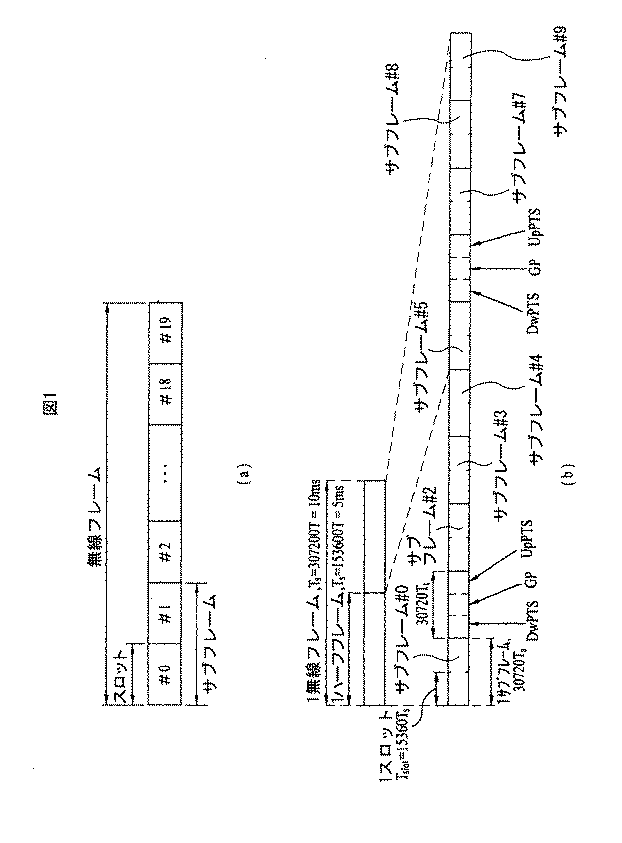
図1を参照して無線フレームの構造について説明する。 The structure of the radio frame will be described with reference to FIG.
セルラOFDM無線パケット通信システムにおいて、上り/下りリンクデータパケット送信はサブフレーム単位に行われ、1サブフレームは、複数のOFDMシンボルを含む一定の時間区間と定義される。3GPP LTE標準では、周波数分割2重通信(FDD)に適用可能なタイプ1無線フレーム構造と、時分割2重通信(TDD)に適用可能なタイプ2無線フレーム構造とをサポートする。
In a cellular OFDM wireless packet communication system, uplink / downlink data packet transmission is performed in units of subframes, and one subframe is defined as a certain time interval including a plurality of OFDM symbols. The 3GPP LTE standard supports a
図1(a)は、タイプ1無線フレームの構造を例示する図である。下りリンク無線フレームは10個のサブフレームで構成され、1個のサブフレームは時間領域において2個のスロットで構成される。1個のサブフレームを送信するためにかかる時間を送信時間間隔(TTI)という。例えば、1サブフレームの長さは1msであり、1スロットの長さは0.5msであってよい。1スロットは時間領域において複数のOFDMシンボルを含み、周波数領域において複数のリソースブロック(RB)を含む。3GPP LTEシステムでは、下りリンクでOFDMAを用いるため、OFDMシンボルが1シンボル区間を表す。OFDMシンボルは、SC−FDMAシンボル又はシンボル区間と呼ばれることもある。リソースブロックはリソース割当単位であり、1スロットにおいて複数個の連続した副搬送波を含むことができる。
FIG. 1A is a diagram illustrating the structure of a
1スロットに含まれるOFDMシンボルの数は、循環プレフィクス(CP)の構成によって異なることがある。CPには拡張CPと正規CPとがある。例えば、OFDMシンボルが正規CPによって構成された場合、1スロットに含まれるOFDMシンボルの数は7個であってよい。OFDMシンボルが拡張CPによって構成された場合、1 OFDMシンボルの長さが増加するため、1スロットに含まれるOFDMシンボルの数は、正規CPの場合に比べて少ない。拡張CPの場合、例えば、1スロットに含まれるOFDMシンボルの数は6個であってよい。端末が速い速度で移動する場合などのようにチャネル状態が不安定な場合は、シンボル間干渉をより減らすために拡張CPを用いてもよい。 The number of OFDM symbols included in one slot may vary depending on the configuration of the cyclic prefix (CP). There are extended CPs and regular CPs. For example, when the OFDM symbol is configured by a regular CP, the number of OFDM symbols included in one slot may be seven. When an OFDM symbol is configured by an extended CP, the length of one OFDM symbol increases, so that the number of OFDM symbols included in one slot is smaller than that of a regular CP. In the case of the extended CP, for example, the number of OFDM symbols included in one slot may be six. When the channel state is unstable, such as when the terminal moves at a high speed, an extended CP may be used to further reduce intersymbol interference.
正規CPが用いられる場合、1スロットは7個のOFDMシンボルを含み、1サブフレームは14個のOFDMシンボルを含む。このとき、各サブフレームにおける先頭の2個又は3個のOFDMシンボルは物理下りリンク制御チャネル(PDCCH)に割り当て、残りのOFDMシンボルは物理下りリンク共有チャネル(PDSCH)に割り当てることができる。 When regular CP is used, one slot includes 7 OFDM symbols, and one subframe includes 14 OFDM symbols. At this time, the first two or three OFDM symbols in each subframe can be allocated to the physical downlink control channel (PDCCH), and the remaining OFDM symbols can be allocated to the physical downlink shared channel (PDSCH).
図1(b)は、タイプ2無線フレームの構造を示す図である。タイプ2無線フレームは、2ハーフフレームで構成される。各ハーフフレームは、5サブフレームと、下りリンクパイロット時間スロット(DwPTS)、保護区間(GP)及び上りリンクパイロット時間スロット(UpPTS)とで構成され、ここで、1サブフレームは2スロットで構成される。DwPTSは、端末での初期セル探索、同期化又はチャネル推定に使用される。UpPTSは、基地局でのチャネル推定及び端末との上りリンク送信同期に用いられる。保護区間は、上りリンクと下りリンクとの間に下りリンク信号の多重経路遅延によって上りリンクで生じる干渉を除去するための区間である。一方、無線フレームのタイプにかかわらず、1個のサブフレームは2個のスロットで構成される。
FIG. 1B is a diagram illustrating the structure of a
無線フレームの構造は例示に過ぎず、無線フレームに含まれるサブフレームの数、サブフレームに含まれるスロットの数、又はスロットに含まれるシンボルの数は様々に変更することができる。 The structure of the radio frame is merely an example, and the number of subframes included in the radio frame, the number of slots included in the subframe, or the number of symbols included in the slots can be variously changed.
図2は、下りリンクスロットにおけるリソースグリッドを示す図である。同図で、1下りリンクスロットは時間領域で7個のOFDMシンボルを含み、1リソースブロック(RB)は周波数領域で12個の副搬送波を含むとしたが、本発明はこれに制限されない。例えば、正規CPでは1スロットが7 OFDMシンボルを含むが、拡張CPでは1スロットが6 OFDMシンボルを含むことがある。リソースグリッド上のそれぞれの要素をリソース要素と呼ぶ。1リソースブロックは12×7個のリソース要素を含む。下りリンクスロットに含まれるリソースブロックの個数NDLは、下り送信帯域幅による。上りリンクスロットの構造は下りリンクスロットの構造と同一であってよい。 FIG. 2 is a diagram illustrating a resource grid in a downlink slot. In the figure, one downlink slot includes 7 OFDM symbols in the time domain, and one resource block (RB) includes 12 subcarriers in the frequency domain. However, the present invention is not limited to this. For example, one slot may contain 7 OFDM symbols in regular CP, but one slot may contain 6 OFDM symbols in extended CP. Each element on the resource grid is called a resource element. One resource block includes 12 × 7 resource elements. The number N DL of resource blocks included in the downlink slot depends on the downlink transmission bandwidth. The structure of the uplink slot may be the same as the structure of the downlink slot.
図3は、下りリンクサブフレームの構造を示す図である。1サブフレーム内で1番目のスロットの先頭部の最大3個のOFDMシンボルは、制御チャネルが割り当てられる制御領域に該当する。残りのOFDMシンボルは、物理下りリンク共有チャネル(PDSCH)が割り当てられるデータ領域に該当する。3GPP LTEシステムで用いられる下りリンク制御チャネルには、例えば、物理制御フォーマット指示子チャネル(PCFICH)、物理下りリンク制御チャネル(PDCCH)、物理HARQ指示子チャネル(PHICH)などがある。PCFICHは、サブフレームの最初のOFDMシンボルで送信され、サブフレーム内の制御チャネル送信に使われるOFDMシンボルの個数に関する情報を含む。PHICHは、上り送信の応答としてHARQ ACK/NACK信号を含む。PDCCHで送信される制御情報を、下りリンク制御情報(DCI)という。DCIは、上りリンクリンクスケジュール情報、下りリンクスケジュール情報又は任意の端末グループに対する上りリンク送信電力制御命令を含む。PDCCHは、下りリンク共有チャネル(DL−SCH)のリソース割当及び送信フォーマット、上りリンク共有チャネル(UL−SCH)のリソース割当情報、呼出しチャネル(PCH)の呼出し情報、DL−SCH上のシステム情報、PDSCH上で送信されるランダム接続応答のような上位層制御メッセージのリソース割当、任意の端末グループ内の個別端末に対する送信電力制御命令の集合、送信電力制御情報、IP電話(VoIP)の活性化などを含むことができる。複数のPDCCHが制御領域内で送信され、端末は複数のPDCCHを監視することもある。PDCCHは、一つ以上の連続する制御チャネル要素(CCE)の集合(aggregation)で送信される。CCEは、無線チャネルの状態に基づく符号化速度でPDCCHを提供するために使われる論理割当単位である。CCEは、複数個のリソース要素グループに対応する。PDCCHのフォーマット及び利用可能なビット数は、CCEの個数と、CCEによって提供される符号化速度との相関関係によって決定される。基地局は、端末に送信されるDCIによってPDCCHフォーマットを決定し、制御情報に巡回冗長検査ビット(CRC)を付加する。CRCは、PDCCHの所有者又は用途によって無線ネットワーク一時識別子(RNTI)という識別子でマスクされる。PDCCHが特定端末に対するものであるとき、端末のセルRNTI(C−RNTI)識別子をCRCにマスクすることができる。又は、PDCCHが呼出しメッセージに対するものであるとき、呼出し指示子RNTI(P−RNTI)をCRCにマスクすることができる。PDCCHがシステム情報(より具体的には、システム情報ブロック(SIB))に対するものであるとき、システム情報識別子及びシステム情報RNTI(SI−RNTI)をCRCにマスクすることができる。端末のランダム接続プリアンブルの送信に対する応答であるランダム接続応答を表すために、ランダム接続RNTI(RA−RNTI)をCRCにマスクすることができる。 FIG. 3 is a diagram illustrating a structure of a downlink subframe. A maximum of three OFDM symbols at the beginning of the first slot in one subframe correspond to a control region to which a control channel is allocated. The remaining OFDM symbols correspond to a data area to which a physical downlink shared channel (PDSCH) is allocated. Examples of the downlink control channel used in the 3GPP LTE system include a physical control format indicator channel (PCFICH), a physical downlink control channel (PDCCH), and a physical HARQ indicator channel (PHICH). The PCFICH is transmitted in the first OFDM symbol of the subframe and includes information on the number of OFDM symbols used for control channel transmission in the subframe. The PHICH includes a HARQ ACK / NACK signal as an uplink transmission response. Control information transmitted on the PDCCH is referred to as downlink control information (DCI). DCI includes uplink schedule information, downlink schedule information, or an uplink transmission power control command for an arbitrary terminal group. PDCCH includes downlink shared channel (DL-SCH) resource allocation and transmission format, uplink shared channel (UL-SCH) resource allocation information, paging channel (PCH) paging information, system information on DL-SCH, Resource allocation of upper layer control messages such as random connection responses transmitted on PDSCH, collection of transmission power control commands for individual terminals in an arbitrary terminal group, transmission power control information, activation of IP phone (VoIP), etc. Can be included. A plurality of PDCCHs are transmitted in the control region, and the terminal may monitor a plurality of PDCCHs. The PDCCH is transmitted in an aggregation of one or more consecutive control channel elements (CCE). CCE is a logical allocation unit used to provide PDCCH at a coding rate based on the state of a radio channel. The CCE corresponds to a plurality of resource element groups. The format of the PDCCH and the number of usable bits are determined by the correlation between the number of CCEs and the coding rate provided by the CCEs. The base station determines the PDCCH format based on DCI transmitted to the terminal, and adds a cyclic redundancy check bit (CRC) to the control information. The CRC is masked with an identifier called a radio network temporary identifier (RNTI) depending on the owner or use of the PDCCH. When the PDCCH is for a specific terminal, the cell RNTI (C-RNTI) identifier of the terminal can be masked to CRC. Or, when the PDCCH is for a paging message, the paging indicator RNTI (P-RNTI) can be masked to the CRC. When the PDCCH is for system information (more specifically, system information block (SIB)), the system information identifier and system information RNTI (SI-RNTI) can be masked to CRC. Random connection RNTI (RA-RNTI) can be masked to CRC to represent a random connection response that is a response to the terminal's transmission of a random connection preamble.
図4は、上りリンクサブフレームの構造を示す図である。上りリンクサブフレームは、周波数領域で制御領域とデータ領域とに区別できる。制御領域には上りリンク制御情報を含む物理上りリンク制御チャネル(PUCCH)が割り当てられる。データ領域には、ユーザデータを含む物理上りリンク共有チャネル(PUSCH)が割り当てられる。単一搬送波特性を維持するために、一つの端末はPUCCH及びPUSCHを同時に送信しない。一つの端末のPUCCHは、サブフレームにおいてリソースブロック対(RB pair)に割り当てられる。リソースブロック対に属するリソースブロックは、2スロットに対して別個の副搬送波を占める。これを、PUCCHに割り当てられるリソースブロック対がスロット境界で周波数ホップするという。 FIG. 4 is a diagram illustrating a structure of an uplink subframe. The uplink subframe can be distinguished into a control region and a data region in the frequency domain. A physical uplink control channel (PUCCH) including uplink control information is allocated to the control area. A physical uplink shared channel (PUSCH) including user data is allocated to the data area. In order to maintain single carrier characteristics, one terminal does not transmit PUCCH and PUSCH simultaneously. The PUCCH of one terminal is assigned to a resource block pair (RB pair) in a subframe. Resource blocks belonging to resource block pairs occupy separate subcarriers for two slots. This is called a resource block pair allocated to the PUCCH frequency hops at the slot boundary.
DCIフォーマットDCI format
現行のLTE−A(release 10)によれば、DCIフォーマット0、1、1A、1B、1C、1D、2、2A、2B、2C、3、3A、4が定義されている。ここで、DCIフォーマット0、1A、3、3Aは、後述するブラインド復号回数を減らすように、同一のメッセージサイズを有するように規定されている。このようなDCIフォーマットは、送信しようする制御情報の用途によって、i)上りリンク承認に用いられるDCIフォーマット0、4、ii)下りリンクスケジュール割当に用いられるDCIフォーマット1、1A、1B、1C、1D、2、2A、2B、2C、iii)電力制御命令のためのDCIフォーマット3、3Aに区別できる。
According to the current LTE-A (release 10), DCI formats 0, 1, 1A, 1B, 1C, 1D, 2, 2A, 2B, 2C, 3, 3A, and 4 are defined. Here, the DCI formats 0, 1A, 3, 3A are defined to have the same message size so as to reduce the number of times of blind decoding described later. Such DCI format depends on the use of control information to be transmitted, i)
上りリンク承認に用いられるDCIフォーマット0は、後述する搬送波集約において必要な搬送波指示子、DCIフォーマット0とDCIフォーマット1Aとを区別するのに用いられるオフセット(フラグ)、上りリンクのPUSCH送信において周波数ホップが用いられるか否かを通知する周波数ホップフラグ、端末がPUSCH送信に用いるべきリソースブロック割当に関する情報、変調及び符号化方式、HARQプロセスと関連して初期送信のためにバッファを空にするのに用いられる新規データ指示子、PUSCHのための送信電力制御命令(TPC)、DMRSのための巡回シフト情報、時分割2重通信(TDD)動作で必要な上りリンクインデクス(UL index)及びチャネル品質指示子要求情報(又はチャネル状態情報(CSI)要求情報)などを含むがことができる。一方、DCIフォーマット0は、同期式HARQを用いるため、下りリンクスケジュール割当に関するDCIフォーマットとは違い、冗長バージョンを含まない。搬送波オフセットは、搬送波間(cross carrier)スケジュールが用いられない場合にはDCIフォーマットに含まれない。
DCIフォーマット4は、LTE−Aリリース10で新たに追加されたものであり、LTE−Aにおいて上りリンク送信に空間多重化が適用されることをサポートする。DCIフォーマット4は空間多重化のための情報を更に含むため、DCIフォーマット0と比較してより大きいメッセージサイズを有し、DCIフォーマット0に含まれる制御情報に追加の制御情報を更に含む。すなわち、DCIフォーマット4は、2番目の送信ブロックのための変調及び符号化方式、多アンテナ送信のためのプリコーディング情報、測定参照信号(SRS)要求情報を更に含む。一方、DCIフォーマット4はDCIフォーマット0よりも大きいサイズを有するため、DCIフォーマット0と1Aとを区別するオフセットは含まない。
下りリンクスケジュール割当に関連したDCIフォーマット1、1A、1B、1C、1D、2、2A、2B、2Cは、空間多重化をサポートしない1、1A、1B、1C、1Dと、空間多重化をサポートする2、2A、2B、2Cとに区別できる。 DCI formats 1, 1A, 1B, 1C, 1D, 2, 2A, 2B, and 2C related to downlink schedule allocation support spatial multiplexing with 1, 1A, 1B, 1C, and 1D that do not support spatial multiplexing. 2 and 2A, 2B and 2C.
DCIフォーマット1Cは、簡潔(compact)な下りリンク割当であって、周波数連続割当だけをサポートし、他のフォーマットと比較すると搬送波オフセット、冗長バージョンを含まない。 The DCI format 1C is a compact downlink assignment, supports only frequency continuous assignment, and does not include a carrier offset and a redundant version as compared with other formats.
DCIフォーマット1Aは、下りリンクスケジュール及びランダム接続手順のためのフォーマットである。ここには、搬送波オフセット、下りリンク分散型送信が用いられるか否かを通知する表示子、PDSCHリソース割当情報、変調及び符号化方式、冗長バージョン、軟結合(soft combining)のために用いられるプロセッサを通知するためのHARQプロセッサ番号、HARQプロセスと関連して初期送信のためにバッファを空にするのに用いられる新しいデータオフセット、PUCCHのための送信電力制御命令、TDD動作で必要な上りリンクインデクスなどを含むことができる。 The DCI format 1A is a format for a downlink schedule and a random connection procedure. Here, a carrier offset, an indicator for notifying whether downlink distributed transmission is used, PDSCH resource allocation information, modulation and coding scheme, redundancy version, processor used for soft combining HARQ processor number for signaling, new data offset used to empty buffer for initial transmission in conjunction with HARQ process, transmit power control command for PUCCH, uplink index required for TDD operation Etc. can be included.
DCIフォーマット1は、大部分の制御情報がDCIフォーマット1Aと略同様になっている。ただし、DCIフォーマット1Aが連続的なリソース割当に関連するものであるのに対し、DCIフォーマット1は不連続的なリソース割当をサポートする。そのため、DCIフォーマット1はリソース割当ヘッダを更に含み、よって、リソース割当の柔軟性が増大することのトレードオフとして制御信号通知オーバヘッドが多少増加する。
In
DCIフォーマット1B,1Dは、プリコーディング情報を更に含むという点でDCIフォーマット1と共通する。DCIフォーマット1BはPMI確認を、DCIフォーマット1Dは下りリンク電力オフセット情報をそれぞれ含む。その他DCIフォーマット1B、1Dに含まれた制御情報は、DCIフォーマット1Aの制御情報とほとんど一致する。
DCI formats 1B and 1D are common to
DCIフォーマット2、2A、2B、2Cは、基本的にDCIフォーマット1Aに含まれた制御情報の大部分を含み、空間多重化のための情報を更に含む。それらの情報には、2番目の送信ブロックに関する変調及び符号化方式、新しいデータオフセット、及び冗長バージョンが該当する。 The DCI formats 2, 2A, 2B, and 2C basically include most of the control information included in the DCI format 1A, and further include information for spatial multiplexing. Such information includes the modulation and coding scheme for the second transmission block, the new data offset, and the redundancy version.
DCIフォーマット2は、閉ループ空間多重化をサポートし、2Aは開ループ空間多重化をサポートする。両者ともプリコーディング情報を含む。DCIフォーマット2Bは、ビーム形成と結合されたデュアルレイヤ空間多重化をサポートし、DMRSのための巡回シフト情報を更に含む。DCIフォーマット2CはDCIフォーマット2Bの拡張として理解してもよく、8レイヤまでの空間多重化をサポートする。
DCIフォーマット3、3Aは、前述した上りリンク承認及び下りリンクスケジュール割当のためのDCIフォーマットに含まれている送信電力制御情報を補完、すなわち半持続的(semi−persistent)スケジュールをサポートするために用いられるとよい。端末当たり、DCIフォーマット3は1ビット、3Aは2ビットの命令が用いられる。
The DCI formats 3 and 3A are used to complement the transmission power control information included in the DCI format for uplink grant and downlink schedule allocation described above, that is, to support a semi-persistent schedule. It should be done. For each terminal, a 1-bit instruction is used for
上述のようなDCIフォーマットのいずれか一つを一つのPDCCHで送信し、複数のPDCCHを制御領域内で送信してもよい。端末は複数のPDCCHを監視することがある。 Any one of the DCI formats as described above may be transmitted using one PDCCH, and a plurality of PDCCHs may be transmitted within the control region. A terminal may monitor multiple PDCCHs.
PDCCH処理PDCCH treatment
PDCCHをREにマップするとき、連続した論理割当単位である制御チャネル要素(CCE)が用いられる。1個のCCEは複数(例えば、9個)のリソース要素グループ(REG)を含み、1個のREGは、参照信号(RS)を除外した状態で隣接する4個のREで構成される。 When mapping PDCCH to RE, a control channel element (CCE), which is a continuous logical allocation unit, is used. One CCE includes a plurality (for example, nine) of resource element groups (REG), and one REG is configured by four adjacent REs excluding the reference signal (RS).
特定のPDCCHのために必要なCCEの個数は、制御情報のサイズであるDCIペイロード、セル帯域幅、チャネル符号化速度などによって異なってくる。具体的に、特定のPDCCHのためのCCEの個数を、次の表1のように、PDCCHフォーマットによって定義することができる。 The number of CCEs required for a specific PDCCH varies depending on the DCI payload, which is the size of control information, the cell bandwidth, the channel coding rate, and the like. Specifically, the number of CCEs for a specific PDCCH can be defined according to the PDCCH format as shown in Table 1 below.
前述した通り、PDCCHには4種類のフォーマットのいずれか一つを利用できるが、そのフォーマットは端末に通知されない。そのため、端末にとってはPDCCHフォーマットを知らないまま復号をしなければならない。これをブラインド復号という。ただし、端末が下りリンクに用いられる可能な全CCEを各PDCCHフォーマットに対して復号することは大きな負担となるため、スケジューラに対する制約及び復号試行回数を考慮して探索空間を定義する。 As described above, any one of four types of formats can be used for the PDCCH, but the format is not notified to the terminal. Therefore, the terminal must perform decoding without knowing the PDCCH format. This is called blind decoding. However, since it is a heavy burden for the terminal to decode all possible CCEs used for the downlink for each PDCCH format, the search space is defined in consideration of restrictions on the scheduler and the number of decoding attempts.
すなわち、探索空間は、集約レベル(Aggregation Level)上で端末が復号を試行するCCEからなる候補PDCCHの集合である。ここで、集約レベル及びPDCCH候補の数を次の表2のように定義することができる。 That is, the search space is a set of candidate PDCCHs made up of CCEs that the terminal tries to decode on an aggregation level (Aggregation Level). Here, the aggregation level and the number of PDCCH candidates can be defined as shown in Table 2 below.
上記の表2から分かるように、4種類の集約レベルが存在するため、端末は各集約レベルによって複数個の探索空間を有する。また、表2に表すように、探索空間は、端末特定探索空間と共通探索空間とに区別できる。端末特定探索空間は特定の端末のためのものであり、各端末は、端末特定探索空間を監視して(可能なDCIフォーマットによってPDCCH候補集合に対して復号を試行して)、PDCCHにマスクされているRNTI及びCRCを確認し、有効な場合、制御情報を取得することができる。 As can be seen from Table 2 above, since there are four types of aggregation levels, the terminal has a plurality of search spaces according to each aggregation level. Further, as shown in Table 2, the search space can be distinguished into a terminal specific search space and a common search space. The terminal specific search space is for a specific terminal, and each terminal is masked by the PDCCH by monitoring the terminal specific search space (trying decoding on the PDCCH candidate set according to a possible DCI format). RNTI and CRC are confirmed, and if valid, control information can be obtained.
共通探索空間は、システム情報に対する動的スケジュール又は呼出しメッセージなどを含め、複数個の端末又は全端末がPDCCHを受信する必要がある場合のためのものである。ただし、共通探索空間は、リソース運用上、特定端末のためのものとして用いてもよい。また、共通探索空間は端末特定探索空間とオーバラップすることもある。 The common search space is for a case where a plurality of terminals or all terminals need to receive the PDCCH, including a dynamic schedule or call message for system information. However, the common search space may be used for a specific terminal in terms of resource operation. In addition, the common search space may overlap with the terminal specific search space.
上記の探索空間は具体的に次の式1によって決定することができる。
The above search space can be specifically determined by the
ここで、Lは集約レベル、YkはRNTI及びサブフレーム番号kによって決定される変数、m’はPDCCH候補数を表す。m’は、搬送波集約が適用された場合にm’=m+M(L)・nCIであり、そうでない場合はm’=mであり、ここで、m=0,・・・,M(L)−1であり、M(L)はPDCCH候補数である。また、NCCE,kはk番目のサブフレームにおける制御領域の全体CCE個数を表し、iは各PDCCH候補において個別CCEを指定する因子を表し、i=0,・・・,L−1である。共通探索空間において、Ykは常に0に決定される。 Here, L is an aggregation level, Y k is a variable determined by RNTI and subframe number k, and m ′ represents the number of PDCCH candidates. m ′ is m ′ = m + M (L) · n CI when carrier aggregation is applied, otherwise m ′ = m, where m = 0,..., M (L ) -1 and M (L) is the number of PDCCH candidates. N CCE, k represents the total number of CCEs in the control region in the kth subframe, i represents a factor for designating an individual CCE in each PDCCH candidate, and i = 0,..., L−1. . In the common search space, Y k is always determined to be 0.
図5は、上記の式1によって定義できる各集約レベルでの端末特定探索空間(陰影部分)を示す。ここで、搬送波集約は適用されておらず、また、NCCE,kは、説明の便宜のために32個とした。
FIG. 5 shows terminal-specific search spaces (shaded portions) at each aggregation level that can be defined by
図5の(a)、(b)、(c)、(d)はそれぞれ、集約レベル1、2、4、8の場合を例示しており、数字はCCE番号を表す。図5で、各集約レベルにおいて探索空間の開始CCEは、上述した通り、RNTI及びサブフレーム番号kで決定されるが、一つの端末に対して同一のサブフレーム内でモジュロ関数とLによって集約レベルごとに異なるように決定されることがあり、Lによって常に集約レベルの倍数だけと決定される。ここで、Ykは例示的にCCE番号18と前提された。開始CCEから端末は、当該集約レベルによって決定されるCCE単位で順次に復号を試行するようになる。例えば、図5の(b)で、端末は、開始CCEであるCCE番号4から集約レベルによって2個のCCE単位で復号を試行する。
(A), (b), (c), and (d) in FIG. 5 exemplify cases of
上述した通り、端末は探索空間に対して復号を試行するが、この復号試行の回数は、DCIフォーマット及びRRC信号通知によって指示される送信モードによって決定される。搬送波集約が適用されない場合、端末は共通探索空間に対してPDCCH候補数6個のそれぞれに対して2種類のDCIサイズ(DCIフォーマット0/1A/3/3A、及びDCIフォーマット1C)を考慮するため、最大12回の復号試行が必要である。端末特定探索空間に対しては、PDCCH候補数(6+6+2+2=16)に対して2種類のDCIサイズを考慮するため、最大32回の復号試行が必要である。したがって、搬送波集約が適用されない場合、最大44回の復号試行が必要である。
As described above, the terminal attempts decoding on the search space, and the number of decoding attempts is determined by the DCI format and the transmission mode indicated by the RRC signal notification. When carrier aggregation is not applied, the terminal considers two types of DCI sizes (
一方、搬送波集約が適用される場合は、下りリンクリソース(構成搬送波)数だけの端末特定探索空間と、DCIフォーマット4のための復号とが追加されるため、最大復号回数は更に増加することになる。
On the other hand, when carrier aggregation is applied, since the terminal specific search space corresponding to the number of downlink resources (constant carrier waves) and decoding for
参照信号Reference signal
無線通信システムにおいてパケットを送信するとき、パケットは無線チャネルを介して送信されるため、送信過程で信号の歪みが発生することがある。歪んだ信号を受信側で正しく受信するためには、チャネル情報を用いて受信信号から歪みを補正しなければならない。チャネル情報を知るために、送信側、受信側の両方で知っている信号を送信し、当該信号がチャネルを介して受信されるときの歪みの度合によってチャネル情報を知る方法を主に用いる。この信号をパイロット信号又は参照信号(Reference Signal)という。 When transmitting a packet in a wireless communication system, since the packet is transmitted through a wireless channel, signal distortion may occur in the transmission process. In order to correctly receive a distorted signal on the receiving side, the distortion must be corrected from the received signal using channel information. In order to know the channel information, a method is mainly used in which a signal known by both the transmission side and the reception side is transmitted and the channel information is known by the degree of distortion when the signal is received via the channel. This signal is referred to as a pilot signal or a reference signal.
多アンテナを用いてデータを送受信する場合は、各送信アンテナと受信アンテナとの間のチャネル状態を知らなければ、正しい信号を受信することができない。そのため、送信アンテナ別に、より詳しくはアンテナポート別にそれぞれの参照信号が存在しなければならない。 When transmitting and receiving data using multiple antennas, a correct signal cannot be received unless the channel state between each transmitting antenna and receiving antenna is known. Therefore, each reference signal must exist for each transmission antenna, more specifically, for each antenna port.
参照信号は上りリンク参照信号と下りリンク参照信号とに区別することができる。現在、LTEシステムには上りリンク参照信号として、
i)PUSCH及びPUCCHを介して送信された情報のコヒーレントな復調のためのチャネル推定のための復調参照信号(DeModulation−Reference Signal、DMRS)
ii)基地局が、ネットワークが異なる周波数上の上りリンクチャネル品質を測定するための測定参照信号(Sounding Reference Signal、SRS)がある。
The reference signal can be distinguished into an uplink reference signal and a downlink reference signal. Currently, as an uplink reference signal in LTE system,
i) Demodulation reference signal (DeModulation-Reference Signal, DMRS) for channel estimation for coherent demodulation of information transmitted via PUSCH and PUCCH
ii) There is a measurement reference signal (SRS) for the base station to measure the uplink channel quality on different frequencies in the network.
一方、下りリンク参照信号としては、
i)セル内のすべての端末が共有するセル特定参照信号(Cell−specific Reference Signal、CRS)、
ii)特定端末だけのための端末特定参照信号(UE−specific Reference Signal)、
iii)PDSCHが送信される場合、コヒーレントな復調のために送信されるDMRS、
iv)下りリンクDMRSが送信される場合、チャネル状態情報(CSI)を伝達するためのチャネル状態情報参照信号(CSI−RS)、
v)MBMS単一周波数網(MBSFN)モードで送信される信号に対するコヒーレントな復調のために送信されるMBSFN参照信号、
vi)端末の地理的位置情報を推定するために用いられる測位参照信号(Positioning Reference Signal)、
がある。
On the other hand, as a downlink reference signal,
i) Cell-specific reference signal (CRS) shared by all terminals in the cell,
ii) a terminal-specific reference signal (UE-specific Reference Signal) for only a specific terminal;
iii) if PDSCH is transmitted, DMRS transmitted for coherent demodulation,
iv) When downlink DMRS is transmitted, channel state information reference signal (CSI-RS) for transmitting channel state information (CSI),
v) MBSFN reference signal transmitted for coherent demodulation on signals transmitted in MBMS single frequency network (MBSFN) mode;
vi) a positioning reference signal (Positioning Reference Signal) used to estimate the geographical location information of the terminal;
There is.
参照信号はその目的によって2種類に大別することができ、チャネル情報取得のための参照信号とデータ復調のための参照信号とがある。前者は、UEが下りリンクのチャネル情報を取得できるようにするためのもので、広帯域で送信しなければならず、特定サブフレームで下りリンクデータを受信しない端末でもその参照信号を受信しなければならない。また、これはハンドオーバなどの状況でも用いられる。後者は、基地局が下りリンクデータを送信するとき、該当のリソースで共に送信する参照信号であり、端末は当該参照信号を受信することによってチャネル測定をし、データを復調することができる。この参照信号はデータが送信される領域で送信しなければならない。 Reference signals can be broadly classified into two types according to their purposes: reference signals for channel information acquisition and reference signals for data demodulation. The former is for enabling the UE to acquire downlink channel information, which must be transmitted in a wide band, and a terminal that does not receive downlink data in a specific subframe must also receive the reference signal. Don't be. This is also used in situations such as handover. The latter is a reference signal that is transmitted together with the corresponding resource when the base station transmits downlink data, and the terminal can measure the channel by receiving the reference signal and demodulate the data. This reference signal must be transmitted in an area where data is transmitted.
CRSはチャネル情報取得及びデータ復調の二つの目的に用いられ、端末特定参照信号はデータ復調用にだけ用いられる。CRSは、広帯域に対して毎サブフレームごとに送信され、基地局の送信アンテナ個数によって最大4個のアンテナポートに対する参照信号が送信される。 CRS is used for the two purposes of channel information acquisition and data demodulation, and the terminal specific reference signal is used only for data demodulation. The CRS is transmitted for each subframe for a wideband, and reference signals for a maximum of four antenna ports are transmitted according to the number of transmission antennas of the base station.
例えば、基地局の送信アンテナ数が2個の場合、0番及び1番のアンテナポートに対するCRSが送信され、4個の場合、0〜3番のアンテナポートに対するCRSがそれぞれ送信される。 For example, when the number of transmission antennas of the base station is 2, CRSs for the 0th and 1st antenna ports are transmitted, and when it is 4, CRSs for the 0-3rd antenna ports are transmitted.
図6は、既存の3GPP LTEシステム(例えば、リリース−8)において定義するCRS及びDRSが下りリンクリソースブロック対上にマップされるパターンを示す図である。参照信号がマップされる単位としての下りリンクリソースブロック対は、時間上で1サブフレーム×周波数上で12副搬送波の単位で表現することができる。すなわち、1リソースブロック対は、時間上で、正規CPの場合(図6(a))は14個のOFDMシンボル長、拡張CPの場合(図6(b))は12個のOFDMシンボル長を有する。 FIG. 6 is a diagram illustrating a pattern in which CRS and DRS defined in an existing 3GPP LTE system (for example, Release-8) are mapped on a downlink resource block pair. A downlink resource block pair as a unit to which a reference signal is mapped can be expressed in units of 12 subcarriers in 1 subframe × frequency in time. That is, one resource block pair has 14 OFDM symbol lengths in the case of regular CP (FIG. 6 (a)) and 12 OFDM symbol lengths in the case of extended CP (FIG. 6 (b)). Have.
図6は、基地局が4個の送信アンテナをサポートするシステムにおいて、参照信号の、リソースブロック対上における位置を示している。図6で、「0」、「1」、「2」及び「3」で表示されたリソース要素(RE)は、それぞれ、アンテナポートインデクス0、1、2及び3に対するCRSの位置を表す。一方、図6で、「D」で表示されたリソース要素は、DMRSの位置を表す。
FIG. 6 shows a position of a reference signal on a resource block pair in a system in which a base station supports four transmission antennas. In FIG. 6, the resource elements (RE) indicated by “0”, “1”, “2”, and “3” represent the positions of CRSs for the
復調参照信号Demodulation reference signal
DMRSは、端末がPDSCHのためのチャネル推定に用いるように定義された参照信号である。DMRSは送信モード7、8、9で用いることができる。初期にDMRSはアンテナポート5番の単一レイヤ送信のためのものとして定義されたが、以降、最大8個のレイヤの空間多重化のためのものとして拡張された。DMRSは、別名の端末特定参照信号からも分かるように、特定の一つの端末のためにだけ送信されるものである。そのため、その特定端末のためのPDSCHが送信されるRBでだけ、DMRSを送信することができる。
DMRS is a reference signal defined to be used by a terminal for channel estimation for PDSCH. DMRS can be used in
最大8個のレイヤのためのDMRSの生成について説明すると、次の通りである。DMRSとして、次の式5によって生成された参照信号シーケンスr(m)を、式6によって複素値変調シンボルa(p) k,lにマップして送信することができる。図7は、式2によってDMRSが正規CPの場合にサブフレーム上のリソースグリッドにマップされたもので、アンテナポート7〜10に関するものを示している。
The generation of DMRS for up to 8 layers will be described as follows. As DMRS, the reference signal sequence r (m) generated by the following
上記の式6からわかるように、参照信号シーケンスは、複素変調シンボルにマップ時に、アンテナポートによって下記の表5のような直交シーケンス
DMRSは、拡散計数(2又は4)によってそれぞれ異なる方法でチャネル推定を行うことができる。表1を参照すると、アンテナポート7〜10では、直交シーケンスが[a b a b]の形態で反復され、拡散係数が2であり、アンテナポート11〜14での拡散係数は4である。拡散係数が2の場合、端末は、1番目のスロットのDMRSと2番目のスロットのDMRSをそれぞれ拡散係数2で逆拡散した後、時間補間を用いてチャネル推定を行うことができる。拡散係数が4の場合は、サブフレーム全体においてDMRSを拡散係数4で一度に逆拡散してチャネル推定を行うことができる。
The DMRS can perform channel estimation using different methods depending on the spreading factor (2 or 4). Referring to Table 1, for antenna ports 7-10, the orthogonal sequence is repeated in the form [a b a b], the spreading factor is 2, and the spreading factor at antenna ports 11-14 is 4. When the spreading factor is 2, the terminal can despread the DMRS of the first slot and the DMRS of the second slot with the spreading
上述の拡散係数によるチャネル推定は、拡散係数2の場合は、移動性が高い場合、時間補間を適用することによる利得と、1番目のスロットにおけるDMRSで逆拡散ができることによる復号時間上の利得とを得ることができ、拡散係数4の場合は、より多数の端末又はランク(rank)をサポートすることができる。
In the channel estimation using the above-described spreading factor, in the case of spreading
DMRSオーバヘッド態様について図8を参照して説明する。図8は、アンテナポート7〜14のそれぞれに対するDMRSのサブフレーム上のマップを示している。図8に示すように、DMRSがリソースグリッドにマップされる位置によって、符号分割多重化(CDM)グループ1(又は第1アンテナポート集合)とCDMグループ2(又は第2アンテナポート集合)とに区別することができる。CDMグループ1に該当するREではアンテナポート7、8、11、13を通したDMRSが、CDMグループ2に該当するREではアンテナポート9、10、12、14を通したDMRSが送信される。すなわち、一つのCDMグループに含まれるアンテナポートでは、DMRSの送信されるREが同一である。CDMグループ1に該当するアンテナポートだけを用いてDMRSが送信されるとき、DMRSのために必要なリソースは12RE、すなわち、DMRSオーバヘッドは12となる。同様に、CDMグループ2に該当するアンテナポートが用いられる場合、DMRSオーバヘッドは24となる。
The DMRS overhead mode will be described with reference to FIG. FIG. 8 shows a map on the DMRS subframe for each of the
リリース11以降のLTEシステムでは、多地点協調送受信(CoMP)、多ユーザ・多入力多出力(MU−MIMO)などによるPDCCHの容量不足及びセル間干渉によるPDCCH性能減少などに対する解決策として、強化PDCCH(E−PDCCH)が検討されている。また、E−PDCCHでは、プリコーディング利得などを得るために、既存のCRSベースのPDCCHとは違い、DMRSに基づいてチャネル推定を行うことができる。 Release 11 and later LTE systems have enhanced PDCCH as a solution to PDCCH capacity shortage due to multi-point coordinated transmission / reception (CoMP), multi-user / multi-input multi-output (MU-MIMO), and PDCCH performance reduction due to inter-cell interference. (E-PDCCH) is being studied. Also, in E-PDCCH, channel estimation can be performed based on DMRS, unlike the existing CRS-based PDCCH, in order to obtain precoding gain and the like.
このようなE−PDCCHの送信について、本発明では、基地局が特定端末にE−PDCCHを送信するために用いるDMRSのアンテナポート及び/又はスクランブルシーケンス(又は、スクランブルシーケンスの初期値)を、E−PDCCHの送信に関係したリソース(例えば、PRB対、サブフレーム、候補位置の開始強化CCE(eCCE)、PRB対内の部分集合のインデクスなど)によって変化させることを提案する。 With regard to such E-PDCCH transmission, in the present invention, the DMRS antenna port and / or the scramble sequence (or the initial value of the scramble sequence) used by the base station for transmitting the E-PDCCH to a specific terminal is designated as E -Propose to change according to resources related to PDCCH transmission (eg, PRB pair, subframe, candidate location start enhancement CCE (eCCE), subset index within PRB pair, etc.).
すなわち、基地局が特定端末にE−PDCCHを送信する場合、そのE−PDCCHのためのDMRSに関連したパラメータを、E−PDCCHに関連したリソースに対してそれぞれ設定することができる。ここで、DMRSパラメータは、前述したように、例えば、アンテナポート、スクランブルシーケンス(スクランブルシーケンスの初期値)であってよいが、本発明はこれに限定されず、その他のDMRSに関連したパラメータであってもよい。また、ここでいう候補位置の開始eCCEとは、L個のCCEを結合して構成した集約レベルLの特定候補位置において、当該位置を構成するL個のCCEのうち、最小のインデクスを持つCCEを指し、(局部型(Localized)E−PDCCHの場合)単一E−PDCCHを構成するL個のeCCEは、いずれも同一のDMRSアンテナポートやスクランブルシーケンスを用いて送信することができる。また、PRB対内の部分集合は、一つのPRB対に属するREを二つ以上の部分集合に分割して形成された各REの部分集合を意味し、互いに異なる部分集合を用いて複数のE−PDCCHを単一PRB対で多重化することができる(例えば、一つのPRB対は4個のECCEで構成でき、各eCCEは4個の強化REG(eREG)で構成できる。局部型E−PDCCHはeCCE単位で送信することができ、分散型E−PDCCHでは、互いに異なるPRB対に属したeREGで一つのeCCEを構成し、E−PDCCH送信を行うことができる。集約レベルによって複数個のeCCEを一つのE−PDCCH(又はDCI)送信に用いることもできる)。また、スクランブルシーケンス(スクランブルシーケンスの初期値)は、セルID、SCIDフィールド、又はこれらとその他様々な変数との組合せで表すことができる。これらの変数の一部又は全部を変化させることによって、スクランブルシーケンスを変化させることができる。 That is, when the base station transmits E-PDCCH to a specific terminal, parameters related to DMRS for the E-PDCCH can be set for resources related to E-PDCCH, respectively. Here, as described above, the DMRS parameter may be, for example, an antenna port or a scramble sequence (an initial value of the scramble sequence). However, the present invention is not limited to this and is a parameter related to other DMRS. May be. Further, the starting eCCE of the candidate position here refers to the CCE having the smallest index among the L CCEs constituting the position at the specific candidate position of the aggregation level L configured by combining the L CCEs. (In case of localized E-PDCCH) L eCCEs constituting a single E-PDCCH can all be transmitted using the same DMRS antenna port and scramble sequence. A subset within a PRB pair means a subset of each RE formed by dividing an RE belonging to one PRB pair into two or more subsets, and a plurality of E− PDCCH can be multiplexed with a single PRB pair (eg, one PRB pair can be composed of 4 ECCEs, and each eCCE can be composed of 4 enhanced REGs (eREGs). In the distributed E-PDCCH, one eCCE can be configured by eREGs belonging to different PRB pairs, and E-PDCCH transmission can be performed. It can also be used for one E-PDCCH (or DCI) transmission). Further, the scramble sequence (initial value of the scramble sequence) can be represented by a cell ID, an SCID field, or a combination of these with various other variables. By changing some or all of these variables, the scramble sequence can be changed.
上記の例示されたE−PDCCH送信に関係するリソースのうち、PRB対について説明すると、本発明は、E−PDCCHが複数の物理リソースブロック(以下、PRB)対のうち、少なくとも一つのPRB対を用いて送信されるとき、E−PDCCHのためのDMRSパラメータが複数のPRB対に対してそれぞれ設定されるものと理解してもよい(ここで、複数のPRB対はE−PDCCH集合と呼ばれることもあり、端末はE−PDCCH集合からブラインド復号のための候補を抽出し、ブラインド復号から、当該候補で実際にE−PDCCHが送信されるか否かを判断できる)。ここで、複数のPRB対は、図9に例示するように、局部型E−PDCCH送信のための一つ以上のPRB対及び/又は分散型E−PDCCH送信のための一つ以上のPRB対を含むことができる。 Among the resources related to the E-PDCCH transmission exemplified above, the PRB pair will be described. The present invention relates to at least one PRB pair among a plurality of physical resource block (hereinafter referred to as PRB) pairs. It may be understood that DMRS parameters for E-PDCCH are respectively set for a plurality of PRB pairs (herein, the plurality of PRB pairs are referred to as an E-PDCCH set). In other words, the terminal can extract a candidate for blind decoding from the E-PDCCH set, and can determine whether the E-PDCCH is actually transmitted by the candidate from the blind decoding). Here, as illustrated in FIG. 9, the plurality of PRB pairs may include one or more PRB pairs for local E-PDCCH transmission and / or one or more PRB pairs for distributed E-PDCCH transmission. Can be included.
したがって、これを反映すれば、上記の本発明の提案は、DMRSパラメータ(例えば、DMRSポート、スクランブルシーケンスパラメータ)が、E−PDCCH送信のために信号通知されたE−PDCCH集合(又は、E−PDCCH集合)に対してそれぞれ設定されるものであってよく、このとき、E−PDCCH集合はそれぞれ、局部型E−PDCCHのためのものか、分散型E−PDCCHのためのものかを設定してもよい。 Therefore, reflecting this, the above proposal of the present invention is that the DMRS parameters (eg, DMRS port, scramble sequence parameters) are signaled for E-PDCCH transmission in the E-PDCCH set (or E-PDCCH). PDCCH set), each of which sets whether the E-PDCCH set is for local E-PDCCH or distributed E-PDCCH. May be.
そのため、DMRSパラメータがスクランブルシーケンス(スクランブルシーケンスの初期値)である場合、スクランブルシーケンス(スクランブルシーケンスの初期値)が各PRB対集合に対してそれぞれ設定される。ここで、各PRB対集合に対して設定されたスクランブルシーケンス(スクランブルシーケンスの初期値)は、上位層信号通知(RRC信号通知)によって端末に伝達することができる。また、DMRSパラメータがアンテナポートである場合、それらのアンテナポートを局部型/分散型E−PDCCH送信のためのPRB対集合に対してそれぞれ設定してもよい。例えば、後述する図9に例示するように、局部型E−PDCCH送信のための一つ以上のPRB対集合ではアンテナポート構成を{7、8、9、10}に、分散型E−PDCCH送信のためのPRB対集合に対してはアンテナポート構成を{7、9、7、9}にそれぞれ設定してもよい。スクランブルシーケンスの場合と同様、PRB対に関連するアンテナポートに関する情報は、上位層信号通知によって端末に伝達することができる。 Therefore, when the DMRS parameter is a scramble sequence (initial value of the scramble sequence), a scramble sequence (initial value of the scramble sequence) is set for each PRB pair set. Here, the scramble sequence (initial value of the scramble sequence) set for each PRB pair set can be transmitted to the terminal by higher layer signal notification (RRC signal notification). When the DMRS parameter is an antenna port, the antenna port may be set for each PRB pair set for local / distributed E-PDCCH transmission. For example, as illustrated in FIG. 9 to be described later, in one or more PRB pair sets for local E-PDCCH transmission, the antenna port configuration is set to {7, 8, 9, 10}, and distributed E-PDCCH transmission is performed. For the PRB pair set for, the antenna port configuration may be set to {7, 9, 7, 9} respectively. As in the case of the scramble sequence, information on the antenna port related to the PRB pair can be transmitted to the terminal by higher layer signal notification.
図9は、DMRSパラメータ(特に、アンテナポート)が一つ以上のPRB対に対してそれぞれ設定されるとともに、局部型E−PDCCH送信のためのPRB対集合及び分散型E−PDCCH送信のためのPRB対集合に対して別個のアンテナポートが割り当てられる例を示す。 FIG. 9 shows that DMRS parameters (particularly antenna ports) are respectively set for one or more PRB pairs, and that PRB pair sets for local E-PDCCH transmission and distributed E-PDCCH transmission are used. An example is shown in which separate antenna ports are assigned to PRB pair sets.
前述したように、E−PDCCHは、送信方式によって局部型送信と分散型送信とに区別でき、一つのeCCEが複数のPRB対に分散して送信されるか否かを、E−PDCCH送信技法を区別する基準とすることができる。すなわち、一つのeCCEが複数のPRB対に分散して送信される場合を分散型送信といい、このとき、一つのeCCEが分散して定義されるリソース集合をeREGということができる。各リソース集合で使用するアンテナポート設定は異なってもよく、これを送信技法と関係付けて適用する場合には、送信技法によって異なったアンテナポート設定を有することができる。 As described above, the E-PDCCH can be classified into local type transmission and distributed type transmission depending on the transmission method, and whether or not one eCCE is distributed and transmitted to a plurality of PRB pairs is determined by the E-PDCCH transmission technique. Can be used as a criterion for distinguishing. That is, a case where one eCCE is distributed and transmitted to a plurality of PRB pairs is referred to as distributed transmission. At this time, a resource set in which one eCCE is distributed and defined can be referred to as eREG. The antenna port settings used in each resource set may be different, and when this is applied in connection with the transmission technique, it may have different antenna port settings depending on the transmission technique.
具体的に、図9を参照すると、図9では、一つのPRB対が8個のeREGで構成され、局部型送信では連続したインデクスを持つ二つのeREGが一つのeCCEを構成するとした。一つのPRB対内でeREGはFDM方式、TDM方式、FDM+TDM方式などで定義でき、干渉のランダム化などのために、インターリービング方式でeREGを定義してもよい。局部型/分散型送信において連続していない二つのeREGが一つのeCCEを構成する場合も本発明の範ちゅうに含まれる。 Specifically, referring to FIG. 9, in FIG. 9, one PRB pair is configured by 8 eREGs, and two eREGs having continuous indexes are configured as one eCCE in local transmission. Within one PRB pair, eREG can be defined by FDM, TDM, FDM + TDM, etc., and eREG may be defined by interleaving for randomization of interference. The case where two eREGs that are not consecutive in the local / distributed transmission form one eCCE is also included in the scope of the present invention.
続いて、図9(a)を参照すると、局部型送信は、低いインデクスのeCCEからアンテナポート{7、8、9、10}の設定を有し、分散型送信ではアンテナポート{7、7、7、7}のアンテナポート設定を有する。eREG単位でアンテナポートが割り当てられるとき、局部型送信は{7、7、8、8、9、9、10、10、11、11}のアンテナポート割当であり、分散型送信は{7、7、7、7、7、7、7、7}のアンテナポート割当である。 Subsequently, referring to FIG. 9 (a), the local type transmission has the setting of the antenna port {7, 8, 9, 10} from the low index eCCE, and in the distributed type transmission, the antenna port {7, 7, 7, 7} antenna port settings. When antenna ports are assigned in units of eREG, local transmission is {7, 7, 8, 8, 9, 9, 10, 10, 11, 11}, and distributed transmission is {7, 7 , 7, 7, 7, 7, 7, 7}.
図9(b)の例示は、eREG単位でアンテナポートが割り当てられる場合であり、局部型送信で{7、7、9、9、8、8、10、10のアンテナポート割当}、分散型送信では{7、9、7、9、7、9、7、9}のアンテナポート割当を仮定した。ここで、局部型送信ではeCCE単位でアンテナポート割当が決定されるとき、アンテナポート割当{7、9、8、10}は信号通知で設定してもよいし、予め設定してもよい。また、分散型送信でeCCE単位のマップを使用しようとする場合、同図の{7、9、7、9、7、9、7、9}を{7、7、9、9、7、7、9、9}のような形態に設定する方法が考慮でき、eCCE単位では{7、9、7、9}のマップを有する。 The example of FIG. 9B is a case where antenna ports are allocated in units of eREG, and {7, 7, 9, 9, 8, 8, 10, 10 antenna port allocation} in local transmission and distributed transmission. Then, antenna port assignment of {7, 9, 7, 9, 7, 9, 7, 9} was assumed. Here, in local transmission, when antenna port assignment is determined in units of eCCE, antenna port assignment {7, 9, 8, 10} may be set by signal notification or may be set in advance. When a map in units of eCCEs is to be used in distributed transmission, {7, 9, 7, 9, 7, 9, 7, 9} in the figure is replaced with {7, 7, 9, 9, 7, 7 , 9, 9} can be considered, and the eCCE unit has a map of {7, 9, 7, 9}.
このような設定はPRB対内のeCCE(又はeREG)とアンテナポートとの関係を送信技法別にあらかじめ設定し、各技法が適用されるPRB対集合を端末に信号通知することができる。 In such a setting, the relationship between the eCCE (or eREG) in the PRB pair and the antenna port is set in advance for each transmission technique, and the PRB pair set to which each technique is applied can be signaled to the terminal.
図10は、DMRSパラメータがPRB(PRB対)単位でそれぞれ設定される特定パターンで変更される例示を示している。すなわち、基地局は端末に上位層信号通知などを通じてDMRSのアンテナポート及び/又はスクランブルシーケンスの変化パターンを通知することができる。その方法の一つに、基地局は特定位置で使用するアンテナポート及び/又はスクランブルシーケンスを通知することができ、それ以外の位置で使用するアンテナポート及び/又はスクランブルシーケンスは、通知したものから一定の規則に従って誘導して認識する方法がある。これは、各位置で使用するDMRSアンテナポート及び/又はスクランブルシーケンスが一定のパターンに定められた状態で、基地局がそのパターンが始まる位置に関するオフセット値を付与することと理解してもよい。 FIG. 10 shows an example in which the DMRS parameter is changed in a specific pattern that is set for each PRB (PRB pair). That is, the base station can notify the terminal of the change pattern of the DMRS antenna port and / or the scramble sequence through a higher layer signal notification or the like. As one of the methods, the base station can notify the antenna port and / or the scramble sequence used at a specific position, and the antenna port and / or the scramble sequence used at the other position is constant from the notified one. There is a method of guiding and recognizing according to the rules. This may be understood as the base station giving an offset value for the position where the pattern starts, with the DMRS antenna port and / or scrambling sequence used at each position defined in a certain pattern.
図10を参照して具体的に説明すると、図10(a)では、SCIDは0に固定された状態で各RB(PRB対)がアンテナポート7、8、9、10を交互に使用する。これは、RB nxはアンテナポート(7+(x mod 4))を使用するものと表現でき、この場合、オフセット値が0に設定されたとすると、これは、RB nxがアンテナポート(7+((x+offset) mod 4)))を使用することを表すことができる。この場合は、アンテナポート7、8、9、10を使用するため、当該端末がE−PDCCH受信に使用する全体DMRSアンテナポートの個数Mportが4である。MportをUEごとに異なるように設定でき、この値も上位層信号を用いて設定することができる。この場合、RB nxのアンテナポートは、次の式7のように一般化した形態で表すことができる。
式7
(7+((x+offset) mod Mport))
Specifically, referring to FIG. 10, in FIG. 10A, each RB (PRB pair) uses
(7 + ((x + offset) mod M port ))
図10(b)は、RB nxがSCID、((floor(x/4)+offset) mod 2)を使用する場合において、offsetが0に設定されたものと説明することができる。 FIG. 10B can be described that RB nx uses SCID, ((floor (x / 4) + offset) mod 2), and offset is set to 0.
又は、各RBで使用するアンテナポート番号は、アンテナポートが変化する周期Periodportと初めて使用するアンテナポート番号Startportとの組合せで表現することもできる。すなわち、最初のPeriodport個のRBではアンテナポート(7+Startport)を使用し、その次のPeriodport個のRBではアンテナポート{7+Startport+1}を使用する形態とも表現することができる。したがって、RB nxが使用するアンテナポートは次の式8で表現することができる。
式8
(7+((Startport+floor(x/Periodport)) mod Mport)
Alternatively, the antenna port number used in each RB can be expressed by a combination of a period period port in which the antenna port changes and an antenna port number Start port used for the first time. That is, using the first Period port number of RB the antenna port (7 + Start port), it can be expressed as the form of using the next Period port number of RB in the antenna port {7 + Start port +1}. Therefore, the antenna port used by RB nx can be expressed by the following
(7 + ((Start port + floor (x / Period port )) mod M port )
上記の式8を適用すると、図10(a)は、Startport=0、Periodport=1、Mport=4の場合に該当し、図10(c)は、Startport=0、Periodport=2、Mport=4の場合に該当する。
When the
以上の説明ではRBごとにDMRSアンテナポート番号及びスクランブルシーケンスが変わるように適用したが、これは例示であり、PRB対集合、候補位置の開始eCCE、及び/又はPRB対内の部分集合ごとに変わるように適用してもよい。 In the above description, the DMRS antenna port number and the scramble sequence are changed for each RB. However, this is an example, and the PRRS pair set, the candidate position start eCCE, and / or the subset within the PRB pair is changed. You may apply to.
図11は、式8に基づいて、端末ごとにそれぞれのアンテナポートが設定された例を示している。具体的に、図11で、端末1(UE1)、端末2(UE2)、端末3(UE3)はそれぞれ、Startport=0、0、1、及びPeriodport=1、2、4の場合のアンテナポート設定を示している。その結果、図11に示すように、特定RBで同一のアンテナポートを持つ端末の組合せが異なることになる。したがって、基地局は、各RBで可能なMU−MIMO対形成を様々に選択することができる。例えば、RB n0及びRB n7では、同一のアンテナポートを持つUE1及びUE2から一つを選択してUE3とMU−MIMOとの対形成(pairing)ができ、RB n1及びRB n6では、同一のアンテナポートを持つUE3及びUE1から一つを選択してUE2とMU−MIMOとの対形成ができる。すなわち、DMRSアンテナポートがすべてのRBに一定に設定された場合、より様々なMU−MIMO対形成が可能となる。
FIG. 11 shows an example in which each antenna port is set for each terminal based on
各RBで(又はPRB対集合、候補位置の開始CCE、及び/又はRB内の部分集合で)使用するDMRSアンテナポート及び/又はスクランブルシーケンスが変化するパターンは、UEに与えられたC−RNTI、セルID、CSI−RSのスクランブルパラメータなどによって変わるように設定でき、これによって、UEごとに異なったパターンを有するように保証することができる。また、各パラメータ間に優先順位を決め、アンテナポートパターンを決定することもできる。例えば、CSI−RSスクランブルパラメータ、セルID、C−RNTIなどに優先順位を決め、再設定メッセージを受信した時点で利用可能パラメータを用いて、アンテナポート割当を再設定することができる。この場合、優先順位に該当するパラメータが利用可能でない場合、次の順位のパラメータを、パターンを決定するために用いることができる。また、これらのパラメータは送信形態によって区別して適用することもできる。例えば、局部型送信ではC−RNTIを用いてアンテナポートパターンを決定し、共有RSを使用する場合は、複数のE−PDCCHが同一のアンテナポートを共有するため、セルID、DMRS、CSI−RSで用いられる仮想セルID、又はスクランブルパラメータなどに基づいてアンテナポートパターンを決定することもできる。 The pattern in which the DMRS antenna port and / or scramble sequence used in each RB (or PRB pair set, starting CCE of candidate position, and / or subset in RB) changes is the C-RNTI given to the UE, It can be set so as to vary depending on the cell ID, the CSI-RS scramble parameter, etc., thereby ensuring that each UE has a different pattern. Further, it is possible to determine the priority order between the parameters and determine the antenna port pattern. For example, priorities can be determined for CSI-RS scramble parameters, cell IDs, C-RNTIs, etc., and antenna port assignments can be reset using available parameters when a reset message is received. In this case, if the parameter corresponding to the priority order is not available, the parameter of the next order can be used to determine the pattern. Also, these parameters can be applied by distinguishing them according to the transmission form. For example, in local transmission, an antenna port pattern is determined using C-RNTI, and when a shared RS is used, since a plurality of E-PDCCHs share the same antenna port, cell ID, DMRS, CSI-RS The antenna port pattern can also be determined based on the virtual cell ID used in FIG.
上述した内容は基本的に、一つのPRB対においてE−PDCCHのための利用可能REの個数が充分である場合を前提に説明された。ただし、FDD/TDDの拡張CP、PBCH/SCHなどが送信されるサブフレーム(又はPRB対集合)、TDDの特別サブフレーム又はCRS/CSI−RS/DMRSなどのRSオーバヘッドが大きいサブフレーム(又はPRB対集合)などでは、一つのPRB対においてE−PDCCHのための利用可能REの個数が減ることがある。 The above description is basically based on the assumption that the number of REs available for E-PDCCH is sufficient in one PRB pair. However, a subframe (or PRB pair set) in which an extended CP of FDD / TDD, PBCH / SCH, or the like is transmitted, a special subframe of TDD, or a subframe with a large RS overhead such as CRS / CSI-RS / DMRS (or PRB) In a pair set), the number of available REs for E-PDCCH may be reduced in one PRB pair.
このようにE−PDCCHのための利用可能リソースの量が不足しており、eCCE(又はeREG)が利用可能リソースだけで構成(すなわち、E−PDCCH送信に用いられるREだけでeCCE(又はeREG)が構成)される場合、PRB対内でeCCE(又はeREG)を構成するREの位置はサブフレーム(又はPRB対)ごとに異なることがある。そのため、PRB対内のeCCE(又はeREG)のインデクスとアンテナポートとの連携(linkage)を予め決定(上位層信号通知で伝達してもよい)し、設定されたPRB対当たりのアンテナポート数よりもeCCE(又はeREG)数が少ないときは、定められたインデクスから(例えば、低いインデクスから、又は高いインデクスから)使用可能な数のアンテナポートだけを使用することを提案する。 Thus, the amount of available resources for E-PDCCH is insufficient, and eCCE (or eREG) is configured with only available resources (ie, eCCE (or eREG) only with RE used for E-PDCCH transmission). In the PRB pair, the position of the RE constituting the eCCE (or eREG) may be different for each subframe (or PRB pair). Therefore, the link (linkage) between the eCCE (or eREG) index and the antenna port in the PRB pair is determined in advance (may be transmitted by higher layer signal notification), and more than the set number of antenna ports per PRB pair. When the number of eCCEs (or eREGs) is small, it is proposed to use only the number of antenna ports that can be used from a defined index (eg, from a low index or from a high index).
このような例示を図12に示す。図12で、陰影で表されたPRB対は、PBCH/SCHなどを含む理由から、当該PRB対ではE−PDCCHのための利用可能リソースの量が一般の場合に比べて半分に減少すると仮定した。したがって、一般の場合にPRB対当たりのeCCE数が4であるとき、当該PRB対でのeCCE数は4から2に減少する。該当の端末に信号通知されたか、又は予め定義されたeCCE対アンテナポートのマップは、PRB対内の低いインデクスから{7、8、9、10}の順序で決定されると仮定した。また、図9と同様に、連続した2個のeREGが一つのeCCEを構成すると仮定した。eREG単位のマップを考慮する場合、図12の左側の一般のPRB対では{7、7、8、8、9、9、10、10}、図12の右側の、eCCEの数が4から2に減少するPRB対では{7、7、8、8}のeREG対アンテナポートのマップがなされてもよい。 Such an example is shown in FIG. In FIG. 12, it is assumed that the PRB pair represented by the shade includes PBCH / SCH and the like, and the amount of available resources for E-PDCCH is reduced by half in the PRB pair as compared with the general case. . Therefore, when the number of eCCEs per PRB pair is 4 in the general case, the number of eCCEs in the PRB pair decreases from 4 to 2. It was assumed that the corresponding terminal was signaled or the predefined eCCE vs. antenna port map was determined in the order {7, 8, 9, 10} from the lower index in the PRB pair. Similarly to FIG. 9, it is assumed that two consecutive eREGs constitute one eCCE. When considering a map in units of eREG, the general PRB pair on the left side of FIG. 12 has {7, 7, 8, 8, 9, 9, 10, 10}, and the number of eCCEs on the right side of FIG. {7, 7, 8, 8} eREG vs. antenna port map may be made for PRB pairs decreasing to.
TDDでも同様に、E−PDCCHのために正規サブフレーム(normal subframe)(又は、利用可能リソースが充分なサブフレーム)でのeCCE(又はeREG)対アンテナポート割当を信号通知するか、又は予め設定しておき、利用可能リソースが減少するスペシャルサブフレームではそのeCCE(又はeREG)対アンテナポート割当のうち一部のアンテナポートだけを使用することができる。なお、追加のオーバヘッドが更に生じる場合(例えば、RSによる)は、いずれか一つのアンテナポート(例えば、アンテナポート{7})だけを使用することもできる。 Similarly in TDD, eCCE (or eREG) vs. antenna port assignment in regular subframe (or subframe with sufficient available resources) is signaled for E-PDCCH or preset. In addition, in a special subframe in which available resources are reduced, only a part of the antenna ports in the eCCE (or eREG) vs. antenna port allocation can be used. In addition, when additional overhead further occurs (for example, due to RS), only one of the antenna ports (for example, antenna port {7}) can be used.
上述した内容を論理ドメインで解釈すると、すなわち、E−PDCCHのためのeCCE(又はeREG)全体にインデクス付けを行うと、二つのPRB対に対してeREGインデクス0〜11(eCCEインデクス0〜5)を導出することができ、PRB対内でのeCCE(又はeREG)対アンテナポートのマップ、すなわち、{7、7、8、8、9、9、10、10})は、PRB対内で最も低いインデクスのリソース集合から解釈することもできる。例えば、図12で、PBCH/SCHが送信されるPRB対でのリソース集合インデクスは8、9、10、11であってよく、{7、7、8、8、9、9、10、10}のアンテナポートマップを適用し、{7、7、8、8}のアンテナポートがeREG8〜11にマップされることを意味してもよい。
When the above-described content is interpreted in the logical domain, that is, when the entire eCCE (or eREG) for E-PDCCH is indexed,
図12で説明された方法と異なる一方法として、E−PDCCHのためのリソースが充分な場合のアンテナポートマップにおいて特定アンテナポートを使用するように信号通知することもできる。これは、特に、干渉調整、RS衝突回避などの目的に利用することができる。 As a method different from the method described in FIG. 12, it is possible to signal to use a specific antenna port in the antenna port map when resources for the E-PDCCH are sufficient. This can be used for purposes such as interference adjustment and RS collision avoidance.
例えば、ネットワークは、E−PDCCHのためのリソースが充分な場合におけるアンテナポートマップに対する優先順位を指定し、アンテナポート数が減少する時、優先順位に基づいてアンテナポートを決定するようにすることもできる。このとき、複数の優先順位をあらかじめ決めておき、セルID、端末ID(C−RNTI)、仮想セルIDなどに基づいて特定優先順位を選択するようにすることもできる。これは上位層信号通知などを用いて伝達することができる。 For example, the network may specify the priority order for the antenna port map when the resources for E-PDCCH are sufficient, and determine the antenna port based on the priority order when the number of antenna ports decreases. it can. At this time, a plurality of priorities may be determined in advance, and the specific priorities may be selected based on the cell ID, terminal ID (C-RNTI), virtual cell ID, and the like. This can be communicated using higher layer signal notification or the like.
又は、各アンテナポート数別にアンテナポート割当のための部分集合を構成し、減少したアンテナポート数に該当する部分集合のうち、使用するアンテナポートマップを上位層信号通知、セルID、端末ID(C−RNTI)、仮想セルIDなどに基づいて決定することもできる。 Alternatively, a subset for antenna port allocation is configured for each number of antenna ports, and among the subsets corresponding to the reduced number of antenna ports, the antenna port map to be used is indicated by higher layer signal notification, cell ID, terminal ID (C -RNTI), virtual cell ID, etc.
前述したように、PRB対内のリソース量の不足によってアンテナポート数が減少する場合に加えて、共有RSの使用、高いレベルの集約レベルなどについては、一つのPRB対内でより少ない数のアンテナポートを用いればよい。ここで、共有RSは、多数のE−PDCCH復号が一つのアンテナポートを通じて行われ、CSIフィードバックが不正確であるか、又は共通制御信号を送信するときに有用である。高いレベルの集約レベルでは多数のeCCE(又はeREG)が一つのDCI送信のために用いられることがあるが、このとき、複数のアンテナポートを使用する場合はチャネル推定の複雑度が増加するため、単一アンテナポート送信が好適である。また、PRB対内のリソース量が不足している場合、例えば、スペシャルサブフレーム、複数のアンテナポートを該当のPRB対に割り当てることは不必要なリソース浪費を招くため、リソース量に合う数のアンテナポートを割り当てることが好ましい。 As described above, in addition to the case where the number of antenna ports decreases due to a shortage of the resource amount in the PRB pair, a smaller number of antenna ports are used in one PRB pair for the use of the shared RS, the high level of aggregation level, and the like. Use it. Here, the shared RS is useful when multiple E-PDCCH decoding is performed through one antenna port and CSI feedback is inaccurate or a common control signal is transmitted. In a high level of aggregation, a large number of eCCEs (or eREGs) may be used for one DCI transmission, but when using multiple antenna ports, the complexity of channel estimation increases. Single antenna port transmission is preferred. Further, when the resource amount in the PRB pair is insufficient, for example, assigning a special subframe and a plurality of antenna ports to the corresponding PRB pair causes unnecessary resource waste. Is preferably assigned.
E−PDCCH送信において考慮すべき問題の一つは、隣接セルとのRS衝突である。RS衝突が発生する場合、特にセル境界に位置している端末にはE−PDCCH性能減少を招くことがある。例えば、サービス提供セルからのE−PDCCHのためのDMRSアンテナポートと、隣接セルがPDSCHのために使用するDMRSポートとが一致する場合がそれに該当する。これを解決できる方法の一つは、隣接セル(又は送信ポイント)が互いに異なるアンテナポートを割り当てることである。ただし、これは、端末特定信号通知による信号通知オーバヘッドが発生するという問題点がある。他の方法として、E−PDCCH送信において少ない数のRSが用いられる場合、RS衝突を避けるために特定アンテナポート(例えば、9、10)を優先的に使用するように設定することもできる。例えば、PRB対当たり一つのアンテナポートが割り当てられる場合には、アンテナポート9又はアンテナポート10を用いてもよく、アンテナポート9及び10がリソース集合単位(例えば、eREG、eCCE)に反復される形態を有してもよい。換言すれば、一般に隣接セルなどでPDSCHのためのDMRS送信時に頻繁に用いるアンテナポート7、8とは異なるアンテナポートを優先して使用するように設定する。以下では、このような脈絡から、共有RSを使用/E−PDCCHのためのリソースが充分でない場合と高いレベルの集約レベルが用いられる場合とを区別して、より具体的に説明する。
One of the problems to be considered in E-PDCCH transmission is RS collision with a neighboring cell. When an RS collision occurs, the E-PDCCH performance may be reduced particularly for a terminal located at a cell boundary. For example, this is the case when the DMRS antenna port for E-PDCCH from the serving cell matches the DMRS port used by the neighboring cell for PDSCH. One way to solve this is to assign different antenna ports to neighboring cells (or transmission points). However, this has a problem that a signal notification overhead due to terminal specific signal notification occurs. As another method, when a small number of RSs are used in E-PDCCH transmission, a specific antenna port (for example, 9, 10) may be set to be used preferentially in order to avoid RS collision. For example, when one antenna port is assigned per PRB pair,
まず、共有RSを使用/E−PDCCHのためのリソースが充分でない場合、特定アンテナポートを優先的に用いることができる。例えば、10、9、8、7の優先順位で、必要なRSアンテナポートの数だけのアンテナポートを割り当てることができる。例えば、1個のアンテナポートの場合はアンテナポート10、2個のアンテナポートの場合はアンテナポート9、10、3個のアンテナポートの場合はアンテナポート9、10、8のように、アンテナポート割当を行うことができる。又は、隣接セルのPDSCHがMU−MIMOを用いない場合、アンテナポート7が主に用いられるため、アンテナポート7を優先的に排除してアンテナポートを選択してもよい。なお、4個のアンテナポートのうち2個のアンテナポートだけを使用する場合、電力増幅利得などのために互いに異なるCDMグループに属したアンテナポートの組合せ(例えば、7,9、又は8,10)でアンテナポートを構成することができ、隣接セルがアンテナポート7、9を使用する可能性が大きいため、特定アンテナポート8、10を使用してもよい。
First, when the resource for using shared RS / E-PDCCH is not sufficient, a specific antenna port can be preferentially used. For example, as many antenna ports as necessary RS antenna ports can be assigned with priority of 10, 9, 8, and 7. For example,
次に、高いレベルの集約レベルが用いられる場合においては代表アンテナポートを用いることができる。代表アンテナポートを決定するとき、該当のPRB対のeCCEのうち、最も低いインデクスのeCCEに配分されたアンテナポートを代表アンテナポートと決定することができる。すなわち、アンテナポート9及び10を最も低いインデクスに配置するアンテナポート割当を用いることができる。最も低いインデクスを使用する場合を含めて特定eCCEのアンテナポートを代表アンテナポートと選定する場合、同様の方法を適用してアンテナポート9又は10を代表アンテナポートと決定することができる。ここで、該当のPRB対に割り当てられたアンテナポートは、一つのPRBが4個のeCCEに分けられる場合、{9、10、7、8}、{10、9、7、8}、{9、10、8、7}{10、9、8、7}とすることができる。又は、上の説明と違い、高いレベルの集約レベルを構成する場合、eCCEにかかわらずアンテナポート9又は10を使用するように制限することもできる。ここで、集約レベル2の場合はスケジュールによって衝突回避が可能なため、上の説明でいう高いレベルの集約レベルは4以上に制限してもよい。
Next, when a high level of aggregation is used, a representative antenna port can be used. When determining the representative antenna port, the antenna port allocated to the eCCE of the lowest index among the eCCEs of the corresponding PRB pair can be determined as the representative antenna port. That is, antenna port assignment can be used in which
上記の説明においてE−PDCCHが送信される各単位リソース集合(例えば、PRB対(集合)、PRB対(eCCE)別部分集合など)別にDMRS設定を、RRC信号通知などを用いて決定することを提案した。これらの説明(例えば、端末がE−PDCCH検出のために各E−PDCCH送信単位別に異なったDMRS設定を用いることができ、各送信単位別DRMS設定はRRC信号通知などを用いて指示できる)は、下記のように二通りの方法として解釈することができる。以下では、説明のために物理ドメイン及び論理ドメインという用語を使用し、物理ドメインはOFDMシンボルマップでのリソース整列(resource arrangement)を意味し、論理ドメインは物理ドメインのうち、E−PDCCH検出のために信号通知された一部のリソースに対するリソース整列を意味する。図13は、物理ドメインと論理ドメインとの関係を示しており、論理ドメインはE−PDCCHの探索空間に該当するリソースを整列したドメインといえる。上記の説明は単一ドメインを基準にしたが、図13のように複数のレイヤを用いた送信でも適用可能である。 In the above description, the DMRS setting is determined using RRC signal notification or the like for each unit resource set (for example, PRB pair (set), PRB pair (eCCE) -specific subset, etc.) to which E-PDCCH is transmitted. Proposed. These explanations (for example, a terminal can use different DMRS settings for each E-PDCCH transmission unit for E-PDCCH detection, and each transmission unit-specific DRMS setting can be instructed using RRC signal notification, etc.) Can be interpreted as two methods as follows. Hereinafter, the terms “physical domain” and “logical domain” will be used for the explanation, and the physical domain means resource alignment in the OFDM symbol map, and the logical domain is one of the physical domains for E-PDCCH detection. Means resource alignment for some resources signaled to. FIG. 13 shows the relationship between the physical domain and the logical domain, and the logical domain can be said to be a domain in which resources corresponding to the E-PDCCH search space are arranged. The above description is based on a single domain, but can be applied to transmission using a plurality of layers as shown in FIG.
続いて、第一の解釈として、基地局は物理ドメインにおいて各単位リソース別DMRS設定を決定し、以降、各端末別E−PDCCH検出のための探索空間を配分することができる。このとき、基地局は各端末に物理ドメイン上で各リソース単位別DMRS設定を信号通知することができる。ここで、リソース別DMRS設定信号通知には、信号通知オーバヘッドを減らすために、上で提案したパターン信号通知方式などを適用することができる。図14(a)は、物理ドメインで1枚のレイヤに複数のアンテナポートを設定する場合を示している。勿論、レイヤ数を増加させたり、スクランブルシーケンスパラメータのようなDMRSパラメータを複数個設定したりすることもできる。 Subsequently, as a first interpretation, the base station can determine the DMRS setting for each unit resource in the physical domain, and thereafter allocate the search space for detecting the E-PDCCH for each terminal. At this time, the base station can notify each terminal of the DMRS setting for each resource unit on the physical domain. Here, in order to reduce signal notification overhead, the pattern signal notification method proposed above or the like can be applied to DMRS setting signal notification for each resource. FIG. 14A shows a case where a plurality of antenna ports are set in one layer in the physical domain. Of course, the number of layers can be increased, or a plurality of DMRS parameters such as scramble sequence parameters can be set.
また、図14(a)では、一つのPRB対が4個の部分集合に分けられ、一つの部分集合がE−PDCCH送信の基本単位として用いられる場合を仮定したが、E−PDCCHが送信されるリソース単位がPRB対であるか、又は多数のPRB対からなる場合にも適用することができる。図14において、基地局は物理ドメインで部分集合ごとに用いられるアンテナポートに対するパターンをRRC信号通知などを用いて端末に指示でき、探索空間に対する信号通知を用いてE−PDCCH検出のためのDMRS設定を最終決定することができる。ここで、アンテナポートに対するパターンは、図14(a)の左側のパターン信号通知Aのようなアンテナポート7、8、9、10の反復、又は右側のパターン信号通知Bのようなアンテナポート9、10、7、8の反復とすることができる。要するに、eCCEに対するDMRS設定を物理ドメインで信号通知した後、探索空間の構成のための信号通知をする方式である。
Further, in FIG. 14A, it is assumed that one PRB pair is divided into four subsets and one subset is used as a basic unit of E-PDCCH transmission. However, E-PDCCH is transmitted. The present invention can also be applied to the case where the resource unit to be used is a PRB pair or a plurality of PRB pairs. In FIG. 14, the base station can instruct the terminal about the antenna port used for each subset in the physical domain using RRC signal notification or the like, and DMRS configuration for E-PDCCH detection using signal notification for the search space. Can be finalized. Here, the pattern for the antenna port is a repetition of
第二の解釈として、論理ドメインでの各リソース単位に対するパターンを信号通知する方法である。すなわち、図14(b)に示すように、まず、従来のLTE/LTE−Aと同様、探索空間に関する情報を物理ドメイン上で信号通知し、以降、論理ドメイン上で、当該探索空間で用いるパターンを信号通知することができる。上記の説明ではアンテナポートに対する設定信号通知を例示したが、スクランブルシーケンスパラメータなど、DMRS設定に使用できる複数のパラメータも適用することができる。 The second interpretation is a method of signaling a pattern for each resource unit in the logical domain. That is, as shown in FIG. 14B, first, similarly to the conventional LTE / LTE-A, information on the search space is signaled on the physical domain, and thereafter, the pattern used in the search space on the logical domain. Can be signaled. In the above description, the notification of the setting signal to the antenna port is exemplified, but a plurality of parameters that can be used for DMRS setting such as a scramble sequence parameter can also be applied.
図15は、本発明の実施形態に係る送信ポイント装置及び端末装置の構成を示す図である。 FIG. 15 is a diagram illustrating a configuration of a transmission point device and a terminal device according to the embodiment of the present invention.
図15を参照すると、本発明に係る送信ポイント装置1510は、受信モジュール1511、送信モジュール1512、プロセッサ1513、メモリ1514及び複数個のアンテナ1515を備えることができる。複数個のアンテナ1515は、MIMO送受信をサポートする送信ポイント装置を意味する。受信モジュール1511は、端末からの上りリンク上の各種信号、データ及び情報を受信することができる。送信モジュール1512は、端末への下りリンク上の各種信号、データ及び情報を送信することができる。プロセッサ1513は、送信ポイント装置1510全般の動作を制御することができる。
Referring to FIG. 15, a
本発明の一実施例に係る送信ポイント装置1510におけるプロセッサ1513は、前述した測定報告、ハンドオーバ、ランダム接続などで必要な事項を処理することができる。
The
送信ポイント装置1510のプロセッサ1513は、その他にも、送信ポイント装置1510が受信した情報、外部に送信する情報などを演算処理する機能を担い、メモリ1514は、演算処理された情報などを所定時間記憶することができ、バッファ(図示せず)などの構成要素に置き換えられてもよい。
In addition, the
続いて、図15を参照すると、本発明に係る端末装置1520は、受信モジュール1521、送信モジュール1522、プロセッサ1523、メモリ1524及び複数個のアンテナ1525を備えることができる。複数個のアンテナ1525は、MIMO送受信をサポートする端末装置を意味する。受信モジュール1521は、基地局からの下りリンク上の各種信号、データ及び情報を受信することができる。送信モジュール1522は、基地局への上りリンク上の各種信号、データ及び情報を送信することができる。プロセッサ1523は、端末装置1520全般の動作を制御することができる。
Subsequently, referring to FIG. 15, the
本発明の一実施例に係る端末装置1520におけるプロセッサ1523は、前述した測定報告、ハンドオーバ、ランダム接続などで必要な事項を処理することができる。
The
端末装置1520のプロセッサ1523は、その他にも、端末装置1520が受信した情報、外部に送信する情報などを演算処理する機能を担い、メモリ1524は、演算処理された情報などを所定時間記憶することができ、バッファ(図示せず)などの構成要素に置き換えられてもよい。
In addition, the
上記のような送信ポイント装置及び端末装置の具体的な構成は、前述した本発明の様々な実施例で説明した事項が独立して適用されたり、又は二つ以上の実施例が同時に適用されたりすることができ、重複する内容は明確性のために説明を省略する。 For the specific configurations of the transmission point device and the terminal device as described above, the matters described in the various embodiments of the present invention described above may be applied independently, or two or more embodiments may be applied simultaneously. For the sake of clarity, the description of overlapping contents is omitted.
また、図15の説明において、送信ポイント装置1510についての説明は、下り送信主体又は上り受信主体としての中継器装置にも同一に適用することができ、端末装置1520についての説明は、下り受信主体又は上り送信主体としての中継器装置にも同一に適用することができる。
In the description of FIG. 15, the description of the
以上の本発明の実施例は、様々な手段、例えば、ハードウェア、ファームウェア、ソフトウェア又はそれらの結合などによって実現することができる。 The above embodiments of the present invention can be realized by various means, for example, hardware, firmware, software, or a combination thereof.
ハードウェアによる実現の場合に、本発明の実施例に係る方法は、一つ又はそれ以上の特定用途集積回路(ASIC)、デジタル信号プロセッサ(DSP)、デジタル信号処理デバイス(DSPD)、プログラム可能論理装置(PLD)、フィールドプログラム可能ゲートアレイ(FPGA)、プロセッサ、コントローラ、マイクロコントローラ、マイクロプロセッサなどによって実現することができる。 When implemented in hardware, the method according to embodiments of the present invention includes one or more application specific integrated circuits (ASICs), digital signal processors (DSPs), digital signal processing devices (DSPDs), programmable logic. It can be realized by a device (PLD), a field programmable gate array (FPGA), a processor, a controller, a microcontroller, a microprocessor, and the like.
ファームウェア又はソフトウェアによる実現の場合、本発明の実施例に係る方法は、以上で説明した機能又は動作を行うモジュール、手順、関数などの形態にすることができる。ソフトウェアコードはメモリユニットに記憶され、プロセッサによって駆動することができる。メモリユニットは、プロセッサの内部又は外部に設けられ、既に公知の様々な手段によってプロセッサとデータを授受することができる。 In the case of implementation by firmware or software, the method according to the embodiment of the present invention can be in the form of a module, procedure, function, or the like that performs the function or operation described above. The software code is stored in a memory unit and can be driven by a processor. The memory unit is provided inside or outside the processor, and can exchange data with the processor by various known means.
以上開示された本発明の好ましい実施例についての詳細な説明は、当業者が本発明を具現して実施できるように提供された。以上では本発明の好適な実施例を参照して説明したが、当該技術の分野における熟練した当業者であれば理解できるであろうが、本発明の領域から逸脱しない範囲内で本発明を様々に修正及び変更することもできる。例えば、当業者は、上記の実施例に記載された各構成を互いに組み合わせて用いてもよい。したがって、本発明は、ここに開示されている実施形態に制限されるものではなく、ここに開示されている原理及び新規な特徴と一致する最も広い範囲を与えるためのものである。 The detailed description of the preferred embodiments of the present invention disclosed above is provided to enable any person skilled in the art to implement and practice the present invention. While the present invention has been described with reference to preferred embodiments thereof, it will be appreciated by those skilled in the art that the present invention may be practiced without departing from the scope of the present invention. It can also be modified and changed. For example, those skilled in the art may use the configurations described in the above embodiments in combination with each other. Accordingly, the present invention is not intended to be limited to the embodiments disclosed herein, but is to provide the widest scope consistent with the principles and novel features disclosed herein.
本発明は、本発明の精神及び必須特徴から逸脱することなく、他の特定の形態に具体化することができる。そのため、上記の詳細な説明はいずれの面においても制約的に解釈してはならず、例示的なものとして考慮しなければならない。本発明の範囲は、添付した請求項の合理的解釈によって定めなければならず、本発明の等価的範囲内における変更はいずれも本発明の範囲に含まれる。本発明は、ここに開示されている実施形態に制限されるものではなく、ここに開示されている原理及び新規な特徴と一致する最も広い範囲を有するものである。また、特許請求の範囲で明示的な引用関係を有しない請求項を結合して実施例を構成してもよく、出願後の補正によって新しい請求項として含めてもよい。 The present invention may be embodied in other specific forms without departing from the spirit and essential characteristics of the invention. As such, the above detailed description should not be construed as limiting in any respect, but should be considered as exemplary. The scope of the invention should be determined by reasonable interpretation of the appended claims, and all changes that come within the equivalent scope of the invention are included in the scope of the invention. The present invention is not limited to the embodiments disclosed herein, but has the widest scope consistent with the principles and novel features disclosed herein. Further, the embodiments may be configured by combining claims that do not have an explicit citation relationship in the scope of claims, and may be included as new claims by amendment after application.
上述したような本発明の実施形態は、様々な移動通信システムに適用可能である。 The embodiment of the present invention as described above can be applied to various mobile communication systems.
Claims (13)
強化物理下りリンク制御チャネル(E−PDCCH)送信のための複数の物理リソースブロック対のうち、少なくとも一つの物理リソースブロック対を用いて端末に対するE−PDCCHを送信するステップを有し、
前記複数の物理リソースブロック対は、一つ以上の物理リソースブロック対集合を含み、
前記E−PDCCHのための復調参照信号の生成に必要なスクランブルシーケンスの初期値を決定するパラメータは、前記各物理リソースブロック対集合に対してそれぞれ設定される、方法。 A method in which a base station transmits control information in a wireless communication system,
Transmitting an E-PDCCH for a terminal using at least one physical resource block pair among a plurality of physical resource block pairs for enhanced physical downlink control channel (E-PDCCH) transmission;
The plurality of physical resource block pairs includes one or more physical resource block pair sets;
A method for determining parameters for determining an initial value of a scramble sequence required for generating a demodulation reference signal for the E-PDCCH, for each physical resource block pair set.
送信モジュールと、
プロセッサと、を備え、
前記プロセッサは、強化物理下りリンク制御チャネル(E−PDCCH)送信のための複数の物理リソースブロック対のうち、少なくとも一つの物理リソースブロック対を用いて端末に対するE−PDCCHを送信し、
前記複数の物理リソースブロック対は、一つ以上の物理リソースブロック対集合を含み、
前記E−PDCCHのための復調参照信号の生成に必要なスクランブルシーケンスの初期値を決定するパラメータは、前記各物理リソースブロック対集合に対してそれぞれ設定される、基地局。 A base station in a wireless communication system,
A transmission module;
And a processor,
The processor transmits an E-PDCCH to a terminal using at least one physical resource block pair among a plurality of physical resource block pairs for enhanced physical downlink control channel (E-PDCCH) transmission,
The plurality of physical resource block pairs includes one or more physical resource block pair sets;
The E-PDCCH parameters to determine the initial value of the scrambling sequence required to generate a demodulation reference signal for the respectively set for each physical resource block pair set, the base station.
Applications Claiming Priority (9)
| Application Number | Priority Date | Filing Date | Title |
|---|---|---|---|
| US201161559139P | 2011-11-13 | 2011-11-13 | |
| US61/559,139 | 2011-11-13 | ||
| US201261598302P | 2012-02-13 | 2012-02-13 | |
| US61/598,302 | 2012-02-13 | ||
| US201261650480P | 2012-05-23 | 2012-05-23 | |
| US61/650,480 | 2012-05-23 | ||
| US201261661331P | 2012-06-18 | 2012-06-18 | |
| US61/661,331 | 2012-06-18 | ||
| PCT/KR2012/009544 WO2013070050A1 (en) | 2011-11-13 | 2012-11-13 | Method and apparatus for transmitting control information in wireless communication system |
Related Child Applications (1)
| Application Number | Title | Priority Date | Filing Date |
|---|---|---|---|
| JP2016053641A Division JP6321707B2 (en) | 2011-11-13 | 2016-03-17 | Method and apparatus for transmitting control information in a wireless communication system |
Publications (2)
| Publication Number | Publication Date |
|---|---|
| JP2015502695A JP2015502695A (en) | 2015-01-22 |
| JP5905972B2 true JP5905972B2 (en) | 2016-04-20 |
Family
ID=48290339
Family Applications (2)
| Application Number | Title | Priority Date | Filing Date |
|---|---|---|---|
| JP2014540961A Active JP5905972B2 (en) | 2011-11-13 | 2012-11-13 | Method and apparatus for transmitting control information in a wireless communication system |
| JP2016053641A Active JP6321707B2 (en) | 2011-11-13 | 2016-03-17 | Method and apparatus for transmitting control information in a wireless communication system |
Family Applications After (1)
| Application Number | Title | Priority Date | Filing Date |
|---|---|---|---|
| JP2016053641A Active JP6321707B2 (en) | 2011-11-13 | 2016-03-17 | Method and apparatus for transmitting control information in a wireless communication system |
Country Status (6)
| Country | Link |
|---|---|
| US (2) | US10244517B2 (en) |
| EP (1) | EP2779495B1 (en) |
| JP (2) | JP5905972B2 (en) |
| KR (1) | KR102131832B1 (en) |
| CN (2) | CN107135054B (en) |
| WO (1) | WO2013070050A1 (en) |
Families Citing this family (29)
| Publication number | Priority date | Publication date | Assignee | Title |
|---|---|---|---|---|
| JP5905972B2 (en) | 2011-11-13 | 2016-04-20 | エルジー エレクトロニクス インコーポレイティド | Method and apparatus for transmitting control information in a wireless communication system |
| US9609638B2 (en) | 2011-12-12 | 2017-03-28 | Sharp Kabushiki Kaisha | Mobile station apparatus, base station apparatus, and communication method |
| JP5957732B2 (en) * | 2011-12-12 | 2016-07-27 | シャープ株式会社 | COMMUNICATION SYSTEM, MOBILE STATION DEVICE, BASE STATION DEVICE, COMMUNICATION METHOD, AND INTEGRATED CIRCUIT |
| CN106788929B (en) * | 2012-01-09 | 2020-01-17 | 华为技术有限公司 | A control channel resource mapping method, base station and user equipment |
| CN109274476B (en) * | 2012-01-09 | 2023-09-26 | 华为技术有限公司 | A control channel transmission and reception method, base station, and user equipment |
| WO2013104425A1 (en) * | 2012-01-13 | 2013-07-18 | Huawei Technologies Co., Ltd. | Method for generating and transmitting demodulation reference signals |
| US9271288B2 (en) * | 2012-02-07 | 2016-02-23 | Qualcomm Incorporated | Resource allocation for enhanced physical downlink control channel (EPDCCH) |
| AU2012373944B2 (en) * | 2012-03-19 | 2015-09-10 | Huawei Technologies Co., Ltd. | Method, base station, and user equipment for transmitting control channel |
| CN103327521B (en) * | 2012-03-20 | 2016-12-14 | 上海贝尔股份有限公司 | For distributing and detect method and the equipment of downlink control channel resource |
| US10448379B2 (en) * | 2012-05-04 | 2019-10-15 | Texas Instruments Incorporated | Enhanced downlink control channel configuration for LTE |
| WO2013169160A1 (en) * | 2012-05-11 | 2013-11-14 | Telefonaktiebolaget L M Ericsson (Publ) | Reference signal design for special subframe configurations |
| US9386583B2 (en) * | 2012-08-10 | 2016-07-05 | Alcatel Lucent | Methods and systems for determining uplink resources |
| KR102130353B1 (en) * | 2012-09-18 | 2020-07-06 | 삼성전자주식회사 | Method and apparatus for generating control channel element in communication system |
| WO2016068072A1 (en) * | 2014-10-31 | 2016-05-06 | 三菱電機株式会社 | Communication system |
| WO2016152315A1 (en) | 2015-03-24 | 2016-09-29 | ソニー株式会社 | Device |
| US10149255B2 (en) | 2015-05-01 | 2018-12-04 | Qualcomm Incorporated | Low latency uplink power control |
| KR102596103B1 (en) | 2015-07-22 | 2023-10-31 | 삼성전자 주식회사 | Method and apparatus for operating machine Type communications in wireless communication system |
| WO2017020201A1 (en) * | 2015-07-31 | 2017-02-09 | Nec Corporation | Methods and apparatuses for transmitting and receiving dmrs indication |
| WO2017160048A2 (en) | 2016-03-14 | 2017-09-21 | Samsung Electronics Co., Ltd. | Method and apparatus for synchronization operation in cellular internet of things networks |
| EP3471485A4 (en) * | 2016-11-01 | 2020-02-26 | LG Electronics Inc. -1- | METHOD FOR TRANSMITTING DOWNLINK CONTROL INFORMATION OF DYNAMIC VARIABLE SIZE IN A WIRELESS COMMUNICATION SYSTEM AND DEVICE THEREFOR |
| CN110249558B (en) * | 2016-12-13 | 2022-03-29 | 诺基亚技术有限公司 | Polarization code for downlink control channel of wireless network |
| EP3565295A4 (en) * | 2016-12-27 | 2020-07-29 | NTT DoCoMo, Inc. | USER TERMINAL AND WIRELESS COMMUNICATION METHOD |
| CN108633012B (en) * | 2017-03-22 | 2021-10-26 | 展讯通信(上海)有限公司 | Time slot aggregation method, device and base station |
| CN109391431B (en) | 2017-08-11 | 2021-10-26 | 华为技术有限公司 | Method, device and computer readable storage medium for acquiring reference signal |
| WO2019142051A1 (en) * | 2018-01-16 | 2019-07-25 | Lenovo (Singapore) Pte. Ltd. | Rate-matching a data transmission around resources |
| CN111757432B (en) * | 2019-03-29 | 2024-04-26 | 华为技术有限公司 | A wake-up method and related device |
| WO2021026912A1 (en) * | 2019-08-15 | 2021-02-18 | Nec Corporation | Transmission and reception of downlink control information |
| US11818705B1 (en) | 2019-09-05 | 2023-11-14 | Sprint Spectrum Lp | Dynamically allocating control channel resources |
| CN115883040B (en) * | 2021-09-28 | 2025-07-01 | 广州慧睿思通科技股份有限公司 | Resource element group bundling information determination method, device, equipment and storage medium |
Family Cites Families (32)
| Publication number | Priority date | Publication date | Assignee | Title |
|---|---|---|---|---|
| US8169956B2 (en) * | 2007-01-26 | 2012-05-01 | Qualcomm Incorporated | Mapping uplink acknowledgement transmission based on downlink virtual resource blocks |
| CN101686070B (en) * | 2008-09-28 | 2013-10-09 | 华为技术有限公司 | Method and network equipment for reconfiguring logical antenna |
| CN104936298B (en) | 2008-11-04 | 2018-07-10 | 苹果公司 | Downlink control structure is provided in first carrier |
| KR101711864B1 (en) * | 2008-12-23 | 2017-03-03 | 엘지전자 주식회사 | Uplink ack/nack signalling in carrier aggregation environment |
| KR100991957B1 (en) * | 2009-01-20 | 2010-11-04 | 주식회사 팬택 | An apparatus and method for generating scrambling code in broadband wireless communication system |
| US8385281B2 (en) * | 2009-01-30 | 2013-02-26 | Interdigital Patent Holdings, Inc. | Method and apparatus for component carrier aggregation in wireless communications |
| JP5131227B2 (en) * | 2009-03-03 | 2013-01-30 | 富士通モバイルコミュニケーションズ株式会社 | Wireless transmission device, wireless reception device, and transmission method |
| CN101895496B (en) * | 2009-05-21 | 2014-04-09 | 中兴通讯股份有限公司 | Transmission processing method and system of control information from base station to relay node |
| WO2010133043A1 (en) * | 2009-05-22 | 2010-11-25 | 华为技术有限公司 | Method for dispatching multi sub-frames and the system, the terminal and the base station thereof |
| KR20110009025A (en) | 2009-07-20 | 2011-01-27 | 엘지전자 주식회사 | Method and apparatus for transmitting uplink control information |
| US8300587B2 (en) * | 2009-08-17 | 2012-10-30 | Nokia Corporation | Initialization of reference signal scrambling |
| KR101711866B1 (en) | 2009-11-27 | 2017-03-03 | 엘지전자 주식회사 | A method and a base station for transmitting downlink control information, and a method and a user equipment for receiving downlink control information |
| US8804586B2 (en) * | 2010-01-11 | 2014-08-12 | Blackberry Limited | Control channel interference management and extended PDCCH for heterogeneous network |
| KR101753586B1 (en) | 2010-02-03 | 2017-07-04 | 엘지전자 주식회사 | Apparatus and method of transmitting control information in wireless communication system |
| CN102149082B (en) * | 2010-02-05 | 2014-11-26 | 中国移动通信集团公司 | Method, device and system for indicating terminal dedicated demodulation reference signal |
| US9118453B2 (en) * | 2010-03-19 | 2015-08-25 | Panasonic Intellectual Property Corporation Of America | Base station and transmission method |
| KR101915271B1 (en) | 2010-03-26 | 2018-11-06 | 삼성전자 주식회사 | Method and apparatus of downlink control indication of resource allocation in wireless communication systems |
| KR101684867B1 (en) * | 2010-04-07 | 2016-12-09 | 삼성전자주식회사 | Transmission and reception method of control information to exploit the spatial multiplexing gain |
| EP2378703A1 (en) | 2010-04-13 | 2011-10-19 | Panasonic Corporation | Mapping of control information to control channel elements |
| US8627171B2 (en) * | 2010-05-03 | 2014-01-07 | Samsung Electronics Co., Ltd. | Techniques for cyclic redundancy check encoding in communication system |
| KR101829831B1 (en) | 2010-05-06 | 2018-02-19 | 엘지전자 주식회사 | Apparatus and method of transmitting control information in wireless communication system |
| US20120054258A1 (en) * | 2010-08-27 | 2012-03-01 | Futurewei Technologies, Inc. | System and Method for Transmitting a Control Channel |
| US10638464B2 (en) * | 2011-04-01 | 2020-04-28 | Futurewei Technologies, Inc. | System and method for transmission and reception of control channels in a communications system |
| CN102170703A (en) * | 2011-05-11 | 2011-08-31 | 电信科学技术研究院 | Method for receiving and transmitting information on physical downlink control channel and equipment thereof |
| CN102231913B (en) | 2011-06-17 | 2015-08-19 | 电信科学技术研究院 | Method, system and equipment for allocating and determining PDCCH |
| US8537862B2 (en) * | 2011-06-30 | 2013-09-17 | Blackberry Limited | Transmit downlink control information with higher order modulation |
| CN102256358B (en) | 2011-07-08 | 2013-11-20 | 电信科学技术研究院 | Data transmission and receiving method, device and system |
| US8995385B2 (en) * | 2011-08-05 | 2015-03-31 | Samsung Electronics Co., Ltd. | Apparatus and method for UE-specific demodulation reference signal scrambling |
| US9084238B2 (en) * | 2011-09-12 | 2015-07-14 | Blackberry Limited | Searching space and operation for enhanced PDCCH in LTE systems |
| US20130083746A1 (en) * | 2011-09-30 | 2013-04-04 | Interdigital Patent Holdings, Inc. | Method and apparatus for allocating resources for an enhanced physical hybrid automatic repeat request indicator channel |
| WO2013058624A1 (en) * | 2011-10-20 | 2013-04-25 | Samsung Electronics Co., Ltd. | Method and apparatus for transmitting and receiving control information in a wireless communication system |
| JP5905972B2 (en) | 2011-11-13 | 2016-04-20 | エルジー エレクトロニクス インコーポレイティド | Method and apparatus for transmitting control information in a wireless communication system |
-
2012
- 2012-11-13 JP JP2014540961A patent/JP5905972B2/en active Active
- 2012-11-13 CN CN201710165882.0A patent/CN107135054B/en not_active Expired - Fee Related
- 2012-11-13 CN CN201280066121.5A patent/CN104040919B/en active Active
- 2012-11-13 KR KR1020147012810A patent/KR102131832B1/en active Active
- 2012-11-13 US US14/358,007 patent/US10244517B2/en active Active
- 2012-11-13 EP EP12847335.2A patent/EP2779495B1/en active Active
- 2012-11-13 WO PCT/KR2012/009544 patent/WO2013070050A1/en not_active Ceased
-
2016
- 2016-03-17 JP JP2016053641A patent/JP6321707B2/en active Active
-
2019
- 2019-01-25 US US16/258,093 patent/US10694513B2/en active Active
Also Published As
| Publication number | Publication date |
|---|---|
| CN107135054A (en) | 2017-09-05 |
| JP2016131392A (en) | 2016-07-21 |
| US20140307700A1 (en) | 2014-10-16 |
| JP6321707B2 (en) | 2018-05-09 |
| KR20140099237A (en) | 2014-08-11 |
| EP2779495A4 (en) | 2015-08-19 |
| CN104040919B (en) | 2017-04-19 |
| US10694513B2 (en) | 2020-06-23 |
| WO2013070050A1 (en) | 2013-05-16 |
| US20190159185A1 (en) | 2019-05-23 |
| JP2015502695A (en) | 2015-01-22 |
| CN104040919A (en) | 2014-09-10 |
| EP2779495B1 (en) | 2021-03-24 |
| US10244517B2 (en) | 2019-03-26 |
| EP2779495A1 (en) | 2014-09-17 |
| KR102131832B1 (en) | 2020-08-05 |
| CN107135054B (en) | 2020-06-12 |
Similar Documents
| Publication | Publication Date | Title |
|---|---|---|
| JP6321707B2 (en) | Method and apparatus for transmitting control information in a wireless communication system | |
| JP6110472B2 (en) | Method and apparatus for receiving control information in wireless communication system | |
| JP6286495B2 (en) | Method and apparatus for receiving downlink signal in wireless communication system | |
| JP5745182B2 (en) | Method and apparatus for transmitting / acquiring control information in a wireless communication system | |
| JP6208340B2 (en) | Method and apparatus for transmitting and receiving signals in a wireless communication system | |
| JP6321851B2 (en) | Control information receiving method and apparatus in wireless communication system | |
| US9750036B2 (en) | Method and apparatus for receiving downlink signals in wireless communication system | |
| EP2897435B1 (en) | Method and apparatus for receiving downlink signal in wireless communication system | |
| KR20140121401A (en) | Method and device for receiving data in wireless communication system | |
| KR20150058191A (en) | Method and apparatus for receiving control information in wireless communication system |
Legal Events
| Date | Code | Title | Description |
|---|---|---|---|
| A977 | Report on retrieval |
Free format text: JAPANESE INTERMEDIATE CODE: A971007 Effective date: 20150527 |
|
| A131 | Notification of reasons for refusal |
Free format text: JAPANESE INTERMEDIATE CODE: A131 Effective date: 20150602 |
|
| A521 | Request for written amendment filed |
Free format text: JAPANESE INTERMEDIATE CODE: A523 Effective date: 20150901 |
|
| TRDD | Decision of grant or rejection written | ||
| A01 | Written decision to grant a patent or to grant a registration (utility model) |
Free format text: JAPANESE INTERMEDIATE CODE: A01 Effective date: 20160216 |
|
| A61 | First payment of annual fees (during grant procedure) |
Free format text: JAPANESE INTERMEDIATE CODE: A61 Effective date: 20160317 |
|
| R150 | Certificate of patent or registration of utility model |
Ref document number: 5905972 Country of ref document: JP Free format text: JAPANESE INTERMEDIATE CODE: R150 |
|
| R250 | Receipt of annual fees |
Free format text: JAPANESE INTERMEDIATE CODE: R250 |
|
| R250 | Receipt of annual fees |
Free format text: JAPANESE INTERMEDIATE CODE: R250 |
|
| R250 | Receipt of annual fees |
Free format text: JAPANESE INTERMEDIATE CODE: R250 |
|
| R250 | Receipt of annual fees |
Free format text: JAPANESE INTERMEDIATE CODE: R250 |
|
| R250 | Receipt of annual fees |
Free format text: JAPANESE INTERMEDIATE CODE: R250 |
|
| R250 | Receipt of annual fees |
Free format text: JAPANESE INTERMEDIATE CODE: R250 |
|
| R250 | Receipt of annual fees |
Free format text: JAPANESE INTERMEDIATE CODE: R250 |