JP5863471B2 - Pluggable optical communication module - Google Patents
Pluggable optical communication module Download PDFInfo
- Publication number
- JP5863471B2 JP5863471B2 JP2012007507A JP2012007507A JP5863471B2 JP 5863471 B2 JP5863471 B2 JP 5863471B2 JP 2012007507 A JP2012007507 A JP 2012007507A JP 2012007507 A JP2012007507 A JP 2012007507A JP 5863471 B2 JP5863471 B2 JP 5863471B2
- Authority
- JP
- Japan
- Prior art keywords
- optical communication
- communication module
- pluggable optical
- case
- cage
- Prior art date
- Legal status (The legal status is an assumption and is not a legal conclusion. Google has not performed a legal analysis and makes no representation as to the accuracy of the status listed.)
- Active
Links
- 230000003287 optical effect Effects 0.000 title claims description 77
- 239000000758 substrate Substances 0.000 claims description 14
- 238000003780 insertion Methods 0.000 claims description 13
- 230000037431 insertion Effects 0.000 claims description 13
- 239000006096 absorbing agent Substances 0.000 claims description 4
- 239000013013 elastic material Substances 0.000 claims description 3
- 230000011218 segmentation Effects 0.000 claims 1
- 238000012986 modification Methods 0.000 description 7
- 230000004048 modification Effects 0.000 description 7
- 238000010586 diagram Methods 0.000 description 6
- 230000004308 accommodation Effects 0.000 description 1
- 230000005540 biological transmission Effects 0.000 description 1
- 239000004020 conductor Substances 0.000 description 1
- 230000000694 effects Effects 0.000 description 1
- 239000002184 metal Substances 0.000 description 1
- 230000008054 signal transmission Effects 0.000 description 1
Images


Landscapes
- Semiconductor Lasers (AREA)
- Shielding Devices Or Components To Electric Or Magnetic Fields (AREA)
Description
本発明は、プラガブル光通信モジュールに関する。 The present invention relates to a pluggable optical communication module.
プラガブル光通信モジュールは、ホスト装置の内部に設けられた金属製のケージに対して着脱可能な形態である。このプラガブル光通信モジュールはホスト装置に配置された電気コネクタに接続されて光通信を行なう。プラガブル光通信モジュールをホスト装置内で保持するケージは、ホスト装置の外部への電磁障害(EMI: Electromagnetic Interference)を抑制するため、ホスト装置のグラウンドに接地されている。 The pluggable optical communication module is detachable from a metal cage provided inside the host device. This pluggable optical communication module is connected to an electrical connector arranged in the host device to perform optical communication. A cage that holds the pluggable optical communication module in the host device is grounded to the ground of the host device in order to suppress electromagnetic interference (EMI) to the outside of the host device.
例えば、特許文献1では、複数の光通信モジュールが搭載可能なケージを持つホスト装置に装着されて使用されるプラガブル光通信モジュールに導電性の弾性フィンガを両側面に備え、複数のプラガブル光通信モジュールを両側面が互いに隣接するように配置した場合に、一方の側面の弾性フィンガが隣接する他方の側面に接触し、且つ、両側面の弾性フィンガ同士は互いに干渉しないように設けることでホスト装置前方における隙間を狭くしてEMIシールド機能を高める形が開示されている。 For example, in Patent Document 1, a pluggable optical communication module mounted on a host device having a cage on which a plurality of optical communication modules can be mounted is provided with conductive elastic fingers on both side surfaces, and a plurality of pluggable optical communication modules is provided. When both sides are adjacent to each other, the elastic fingers on one side are in contact with the other side, and the elastic fingers on both sides are provided so that they do not interfere with each other. The form which narrows the clearance gap and improves an EMI shielding function is disclosed.
プラガブル光通信モジュールは、ホスト装置の基板に設けられているケージに挿入して使用される。プラガブル光通信モジュールは、ケージとの間に隙間を持った状態で、ホスト装置に配置された電気コネクタに接続する。プラガブル光通信モジュールとホスト装置との電気的なインターフェースは電気コネクタを経由して行なう。プラガブル光通信モジュールと電気コネクタの間では、電磁障害の源となる高周波の電気信号の授受も行なう。 The pluggable optical communication module is used by being inserted into a cage provided on the substrate of the host device. The pluggable optical communication module is connected to an electrical connector arranged in the host device with a gap between the pluggable optical communication module and the cage. The electrical interface between the pluggable optical communication module and the host device is performed via an electrical connector. Between the pluggable optical communication module and the electrical connector, high-frequency electrical signals that cause electromagnetic interference are also exchanged.
近年は信号の伝送量の増大に加えて伝送速度が高速化していて、この電気信号の動作周波数は高くなっている。動作周波数が低い場合は、プラガブル光通信モジュールとケージとの隙間が多少大きくても電磁障害を抑制することが可能であった。しかし、動作周波数が高くなると、プラガブル光通信モジュールとケージとの隙間が小さくても電磁波がこの隙間を通ってホスト装置の外部へ放出されるようになる。 In recent years, in addition to an increase in the amount of signal transmission, the transmission speed has increased, and the operating frequency of this electrical signal has increased. When the operating frequency is low, electromagnetic interference can be suppressed even if the gap between the pluggable optical communication module and the cage is somewhat large. However, when the operating frequency increases, even if the gap between the pluggable optical communication module and the cage is small, electromagnetic waves are emitted through the gap to the outside of the host device.
特許文献1は、フィンガを備えたプラガブル光通信モジュールにのみ採用可能で、複数の光通信モジュールが搭載可能な装置に対して有効な手段である。 Patent Document 1 is an effective means for an apparatus that can be mounted only on a pluggable optical communication module having fingers and on which a plurality of optical communication modules can be mounted.
本発明は、フィンガの有無に関係なく、プラガブル光通信モジュールとホスト装置のケージとの隙間を小さくして、上述した電磁障害(EMI)に対するシールド機能を高めることを目的とする。 An object of the present invention is to improve the shielding function against the electromagnetic interference (EMI) described above by reducing the gap between the pluggable optical communication module and the cage of the host device regardless of the presence or absence of the finger.
(1)本発明に係るプラガブル光通信モジュールは、ホスト装置に配置されたケージに対して挿入して使用するプラガブル光通信モジュールであって、導電性のケースを備え、前記ケースは、分割された複数の分割ケースから構成され、前記複数の分割ケースは、前記ケージへの挿入方向に対して交差する方向に相対的に可動であり、相対的に離れる方向に弾性力が付与されており、前記弾性力によって、少なくとも1つの前記分割ケースが前記ケージの内側に接触することを特徴とする。本発明によれば、弾性力によって分割ケースがケージの内側に接触するので、プラガブル光通信モジュールとホスト装置のケージとの隙間を小さくして、電磁障害(EMI)に対するシールド機能を高めることができる。 (1) A pluggable optical communication module according to the present invention is a pluggable optical communication module that is used by being inserted into a cage disposed in a host device, and includes a conductive case, and the case is divided. It is composed of a plurality of divided cases, and the plurality of divided cases are relatively movable in a direction intersecting the insertion direction into the cage, and elastic force is applied in a direction away from the cage, At least one of the divided cases comes into contact with the inside of the cage by elastic force. According to the present invention, since the split case comes into contact with the inside of the cage by the elastic force, the gap between the pluggable optical communication module and the host device cage can be reduced, and the shielding function against electromagnetic interference (EMI) can be enhanced. .
(2)(1)に記載されたプラガブル光通信モジュールにおいて、前記ケースは、前記ケージへの挿入方向の先端から後端に向けて次第に厚み又は幅が大きくなる部分を有するように構成され、前記厚み又は前記幅を定義する一方の面は、前記ケージの内側に接触する前記少なくとも1つの前記分割ケースの外表面であることを特徴としてもよい。 (2) In the pluggable optical communication module described in (1), the case is configured to have a portion whose thickness or width gradually increases from the front end to the rear end in the insertion direction to the cage, One surface defining the thickness or the width may be an outer surface of the at least one divided case that contacts the inside of the cage.
(3)(2)に記載されたプラガブル光通信モジュールにおいて、前記ケージの内側に接触する前記少なくとも1つの前記分割ケースの前記外表面は、傾斜面であり、前記ケースは、前記ケージへの挿入方向に平行であって前記外表面に交差する面で切断した断面において、くさびの一部に相当する形状を有することを特徴としてもよい。 (3) In the pluggable optical communication module described in (2), the outer surface of the at least one split case that contacts the inside of the cage is an inclined surface, and the case is inserted into the cage. A cross section cut along a plane parallel to the direction and intersecting the outer surface may have a shape corresponding to a part of the wedge.
(4)(2)に記載されたプラガブル光通信モジュールにおいて、前記ケージの内側に接触する前記少なくとも1つの前記分割ケースの前記外表面は、湾曲した凸曲面であり、前記外表面は、前記ケージへの挿入方向に平行な面で切断した断面において、アーチ形状を描くことを特徴としてもよい。 (4) In the pluggable optical communication module described in (2), the outer surface of the at least one split case that contacts the inside of the cage is a curved curved surface, and the outer surface is the cage An arch shape may be drawn in a cross section cut along a plane parallel to the insertion direction.
(5)(1)から(4)のいずれか1項に記載されたプラガブル光通信モジュールにおいて、少なくとも1つの前記分割ケースは、前記弾性力を付与するための弾性材料から構成されていることを特徴としてもよい。 (5) In the pluggable optical communication module described in any one of (1) to (4), at least one of the split cases is made of an elastic material for applying the elastic force. It may be a feature.
(6)(1)から(4)のいずれか1項に記載されたプラガブル光通信モジュールにおいて、前記弾性力を付与するための弾性体をさらに有することを特徴としてもよい。 (6) The pluggable optical communication module described in any one of (1) to (4) may further include an elastic body for applying the elastic force.
(7)(6)に記載されたプラガブル光通信モジュールにおいて、前記ケースに内蔵される基板をさらに有し、前記弾性体は、前記基板に取り付けられていることを特徴としてもよい。 (7) The pluggable optical communication module described in (6) may further include a substrate built in the case, and the elastic body may be attached to the substrate.
(8)(1)から(7)のいずれか1項に記載されたプラガブル光通信モジュールにおいて、少なくとも1つの前記分割ケースは、対向して配置される他の前記分割ケースとの対向面に電磁波吸収体を有することを特徴としてもよい。 (8) In the pluggable optical communication module described in any one of (1) to (7), at least one of the divided cases has an electromagnetic wave on a surface facing the other divided case disposed to face the other. It may be characterized by having an absorber.
(9)(1)から(8)のいずれか1項に記載されたプラガブル光通信モジュールにおいて、前記複数の分割ケースは、トップケースとボトムケースであり、上下方向に可動であることを特徴としてもよい。 (9) In the pluggable optical communication module described in any one of (1) to (8), the plurality of divided cases are a top case and a bottom case, and are movable in the vertical direction. Also good.
以下、本発明の実施の形態について、図面を参照して説明する。 Embodiments of the present invention will be described below with reference to the drawings.
本実施形態の説明ではプラガブル光通信モジュールのフォームファクターの一つであるXFP(10 Gigabit Small Form Factor Pluggable)を例に挙げて説明するが、プラガブル光通信モジュールにはSFP+(Small Form−Factor Pluggable Plus)、CFP2(100G form−factor pluggable 2)、QSFP(Quad Small Form−factor Pluggable)等様々なフォームファクターがあり、あらゆるプラガブル光通信モジュールにも本発明を適用することができる。 In the description of this embodiment, an XFP (10 Gigabit Small Form Factor Pluggable), which is one of the form factors of a pluggable optical communication module, will be described as an example. ), CFP2 (100G form-factor pluggable 2), QSFP (Quad Small Form-factor Pluggable), and the like, and the present invention can be applied to any pluggable optical communication module.
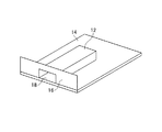
図1は、本発明の実施形態に係るプラガブル光通信モジュールを示す図である。図2は、本発明の実施形態に係るプラガブル光通信モジュールを使用するホスト装置の一部を示す図である。 FIG. 1 is a diagram showing a pluggable optical communication module according to an embodiment of the present invention. FIG. 2 is a diagram illustrating a part of a host device using the pluggable optical communication module according to the embodiment of the present invention.
プラガブル光通信モジュール10は、ホスト装置に配置されたケージ12に対して挿入して使用するものである。ケージ12は、ホスト装置の基板14に取り付けられている。ホスト装置の前面にフロントパネル16が配置されている。フロントパネル16は、プラガブル光通信モジュール10の差込口18を有する。ケージ12は、フロントパネル16の差込口18と連通するように、プラガブル光通信モジュール10の収容空間を有する。
The pluggable
図3は、本発明の実施形態に係るプラガブル光通信モジュール10が挿入されたホスト装置を示す図である。
FIG. 3 is a diagram illustrating a host device into which the pluggable
プラガブル光通信モジュール10は、ケージ12に挿入されると、基板14に設けられた電気コネクタ20と電気的に接続する。フロントパネル16は導電材料から構成され、ホスト装置の図示しないアースと同電位となっており、ホスト装置と基板14からの電磁波をシールドするので、電磁障害(EMI)に対して効果がある。しかしながら、フロントパネル16の差込口18とプラガブル光通信モジュール10の間に隙間が形成されると、高速な電気信号による電磁波が漏れるため、プラガブル光通信モジュール10とケージ12との隙間を小さくすることは、電磁障害(EMI)のシールドにおいて非常に有効となる。
When pluggable
図4は、本発明の実施形態に係るプラガブル光通信モジュール10の断面図である。プラガブル光通信モジュール10は、導電性のケース22を備えている。ケース22は、分割された複数の分割ケース24から構成されている。複数の分割ケース24は、トップケース26とボトムケース28であり、上下方向に可動である。少なくとも1つの分割ケース24(ボトムケース28)は、弾性力を付与するための弾性材料から構成されている。トップケース26とボトムケース28はネジ30によって保持されている。
FIG. 4 is a cross-sectional view of the pluggable
ケース22は、ケージ12への挿入方向の先端から後端に向けて次第に厚み又は幅が大きくなる部分を有するように構成されている。厚み又は幅を定義する一方の面は、ケージ12の内側に接触する少なくとも1つの分割ケース24の外表面である。
The
ケージ12の内側に接触する少なくとも1つの分割ケース24の外表面は、傾斜面である。ケース22は、ケージ12への挿入方向に平行であって外表面に交差する面で切断した断面において、くさびの一部に相当する形状を有する。
The outer surface of at least one divided case 24 that contacts the inside of the
複数の分割ケース24は、ケージ12への挿入方向に対して交差する方向に相対的に可動である。複数の分割ケース24は、相対的に離れる方向に弾性力が付与されている。弾性力によって、少なくとも1つの分割ケース24がケージ12の内側に接触する。
The plurality of divided cases 24 are relatively movable in a direction intersecting the insertion direction into the
図5は、ボトムケース28を示す図である。少なくとも1つの分割ケース24(ボトムケース28)は、対向して配置される他の分割ケース24(トップケース26)との対向面に電磁波吸収体25を有する。これにより、プラガブル光通信モジュール10の内部からの電磁波もシールドすることができ、システム全体の電磁障害対策もより効果的となる。
FIG. 5 is a view showing the bottom case 28. At least one division case 24 (bottom case 28) has an
プラガブル光通信モジュール10の幅(高さ)は、ケージ12に挿入されるとその高さに倣って小さくなる。トップケース26とボトムケース28は、相対的に離れる方向に弾性力が付与されているので、プラガブル光通信モジュール10とケージ12との隙間は小さくなる。
When the pluggable
本実施形態によれば、弾性力によって分割ケース24がケージ12の内側に接触するので、プラガブル光通信モジュール10とホスト装置のケージ12との隙間を小さくして、電磁障害(EMI)に対するシールド機能を高めることができる。(変形例1)
According to the present embodiment, since the split case 24 comes into contact with the inside of the
図6は、本発明の実施形態に係るプラガブル光通信モジュールの変形例1を示す図である。この例では、ケージ12の内側に接触する少なくとも1つの分割ケース124の外表面は、湾曲した凸曲面である。外表面は、ケージ12への挿入方向に平行な面で切断した断面において、アーチ形状を描く。(変形例2)
FIG. 6 is a diagram illustrating a first modification of the pluggable optical communication module according to the embodiment of the present invention. In this example, the outer surface of at least one divided
図7は、本発明の実施形態に係るプラガブル光通信モジュールの変形例2を示す図である。この例では、弾性力は弾性体232によって付与される。ケース222には基板214が内蔵されている。弾性体232は、基板214に取り付けられている。プラガブル光通信モジュール210をケージ12に挿入する前では、弾性体232には力が加えられていないので、弾性力が生じていない。
FIG. 7 is a diagram illustrating a second modification of the pluggable optical communication module according to the embodiment of the present invention. In this example, the elastic force is applied by the
図8は、ケージ12に挿入されたときのプラガブル光通信モジュール210を示す図である。プラガブル光通信モジュール210をケージ12に挿入すると、ボトムケース228はケージ12から上方向の力を受ける。これにより、弾性体232が圧縮され、弾性力が生じる。これにより、プラガブル光通信モジュール210とケージ12との隙間が小さい状態を保ちつつ、プラガブル光通信モジュール210はケージ212に収まる。
FIG. 8 is a diagram showing the pluggable
本発明は、上述した実施の形態に限定されるものではなく種々の変形が可能である。例えば、実施の形態で説明した構成は、実質的に同一の構成、同一の作用効果を奏する構成又は同一の目的を達成することができる構成で置き換えることができる。 The present invention is not limited to the embodiment described above, and various modifications are possible. For example, the configuration described in the embodiment can be replaced with a substantially the same configuration, a configuration that exhibits the same operational effects, or a configuration that can achieve the same purpose.
10 ラガブル光通信モジュール、12 ケージ、14 基板、16 フロントパネル、18 差込口、20 電気コネクタ、22 ケース、24 分割ケース、25 電磁波吸収体、26 トップケース、28 ボトムケース、30 ネジ、124 分割ケース、210 ラガブル光通信モジュール、214 基板、222 ケース、228 ボトムケース、232 弾性体。 10 Ragable optical communication module, 12 cage, 14 substrate, 16 front panel, 18 outlet, 20 electrical connector, 22 case, 24 split case, 25 electromagnetic wave absorber, 26 top case, 28 bottom case, 30 screw, 124 split Case, 210 Ragable optical communication module, 214 substrate, 222 case, 228 bottom case, 232 elastic body.
Claims (7)
導電性のケースを備え、
前記ケースは、分割された複数の分割ケースから構成され、
前記複数の分割ケースは、前記ケージへの挿入方向に対して交差する方向に相対的に可動であり、相対的に離れる方向に弾性力が付与されており、
前記弾性力によって、少なくとも1つの前記分割ケースが前記ケージの内側に接触し、
前記弾性力を付与するための弾性体と、
前記ケースに内蔵される基板と、
をさらに有し、
前記弾性体は、前記基板に取り付けられていることを特徴とするプラガブル光通信モジュール。 A pluggable optical communication module used by being inserted into a cage disposed in a host device,
With a conductive case,
The case is composed of a plurality of divided cases.
The plurality of divided cases are relatively movable in a direction intersecting the insertion direction into the cage, and an elastic force is applied in a direction away from each other.
Due to the elastic force, at least one of the divided cases comes into contact with the inside of the cage ,
An elastic body for applying the elastic force;
A substrate built into the case;
Further comprising
The pluggable optical communication module , wherein the elastic body is attached to the substrate .
導電性のケースを備え、
前記ケースは、分割された複数の分割ケースから構成され、
前記複数の分割ケースは、前記ケージへの挿入方向に対して交差する方向に相対的に可動であり、相対的に離れる方向に弾性力が付与されており、
前記弾性力によって、少なくとも1つの前記分割ケースが前記ケージの内側に接触し、
少なくとも1つの前記分割ケースは、対向して配置される他の前記分割ケースとの対向面に電磁波吸収体を有することを特徴とするプラガブル光通信モジュール。 A pluggable optical communication module used by being inserted into a cage disposed in a host device,
With a conductive case,
The case is composed of a plurality of divided cases.
The plurality of divided cases are relatively movable in a direction intersecting the insertion direction into the cage, and an elastic force is applied in a direction away from each other.
Due to the elastic force, at least one of the divided cases comes into contact with the inside of the cage ,
The pluggable optical communication module according to claim 1, wherein at least one of the split cases has an electromagnetic wave absorber on a surface facing the other split case disposed to face the split case .
前記ケースは、前記ケージへの挿入方向の先端から後端に向けて次第に厚み又は幅が大きくなる部分を有するように構成され、
前記厚み又は前記幅を定義する一方の面は、前記ケージの内側に接触する前記少なくとも1つの前記分割ケースの外表面であることを特徴とするプラガブル光通信モジュール。 The pluggable optical communication module according to claim 1 or 2 ,
The case is configured to have a portion whose thickness or width gradually increases from the front end to the rear end in the insertion direction to the cage,
One surface which defines the said thickness or the said width | variety is an outer surface of the said at least 1 said division | segmentation case which contacts the inner side of the said cage, The pluggable optical communication module characterized by the above-mentioned.
少なくとも1つの前記分割ケースは、前記弾性力を付与するための弾性材料から構成されていることを特徴とするプラガブル光通信モジュール。 The pluggable optical communication module according to claim 2 ,
The pluggable optical communication module, wherein at least one of the divided cases is made of an elastic material for applying the elastic force.
前記弾性力を付与するための弾性体をさらに有することを特徴とするプラガブル光通信モジュール。 The pluggable optical communication module according to claim 2 ,
A pluggable optical communication module, further comprising an elastic body for applying the elastic force.
前記ケースに内蔵される基板をさらに有し、
前記弾性体は、前記基板に取り付けられていることを特徴とするプラガブル光通信モジュール。 The pluggable optical communication module according to claim 5 ,
Further comprising a substrate built in the case,
The pluggable optical communication module, wherein the elastic body is attached to the substrate.
前記複数の分割ケースは、トップケースとボトムケースであり、上下方向に可動であることを特徴とするプラガブル光通信モジュール。 The pluggable optical communication module according to any one of claims 1 to 6 ,
The pluggable optical communication module, wherein the plurality of divided cases are a top case and a bottom case, and are movable in a vertical direction.
Priority Applications (1)
| Application Number | Priority Date | Filing Date | Title |
|---|---|---|---|
| JP2012007507A JP5863471B2 (en) | 2012-01-17 | 2012-01-17 | Pluggable optical communication module |
Applications Claiming Priority (1)
| Application Number | Priority Date | Filing Date | Title |
|---|---|---|---|
| JP2012007507A JP5863471B2 (en) | 2012-01-17 | 2012-01-17 | Pluggable optical communication module |
Publications (2)
| Publication Number | Publication Date |
|---|---|
| JP2013149688A JP2013149688A (en) | 2013-08-01 |
| JP5863471B2 true JP5863471B2 (en) | 2016-02-16 |
Family
ID=49046934
Family Applications (1)
| Application Number | Title | Priority Date | Filing Date |
|---|---|---|---|
| JP2012007507A Active JP5863471B2 (en) | 2012-01-17 | 2012-01-17 | Pluggable optical communication module |
Country Status (1)
| Country | Link |
|---|---|
| JP (1) | JP5863471B2 (en) |
Family Cites Families (6)
| Publication number | Priority date | Publication date | Assignee | Title |
|---|---|---|---|---|
| JPH0576094U (en) * | 1992-03-16 | 1993-10-15 | セイコーエプソン株式会社 | Circuit board grounding structure |
| KR100434230B1 (en) * | 2002-03-26 | 2004-06-04 | 한국몰렉스 주식회사 | High speed communication cable connector assembly |
| EP1511368B1 (en) * | 2003-08-29 | 2015-05-20 | Hirschmann Car Communication GmbH | Sandwich housing for antenna amplifier |
| US7416353B2 (en) * | 2004-10-05 | 2008-08-26 | Sumitomo Electric Industries, Ltd. | Heat dissipating mechanism of a pluggable optical transceiver |
| JP5321215B2 (en) * | 2009-04-17 | 2013-10-23 | Nok株式会社 | Electromagnetic shielding gasket |
| JP5567412B2 (en) * | 2010-06-28 | 2014-08-06 | 日本オクラロ株式会社 | Optical transceiver and electronic device |
-
2012
- 2012-01-17 JP JP2012007507A patent/JP5863471B2/en active Active
Also Published As
| Publication number | Publication date |
|---|---|
| JP2013149688A (en) | 2013-08-01 |
Similar Documents
| Publication | Publication Date | Title |
|---|---|---|
| US9496657B1 (en) | Electrical connector structure | |
| US8808029B2 (en) | High density connector structure for transmitting high frequency signals | |
| CN102763012B (en) | There is the optical transceiver of the EMI tolerance of enhancing | |
| US9306345B2 (en) | High-density cable end connector | |
| JP5869274B2 (en) | Communication device cage | |
| CN104979713B (en) | Cable Connector with Shielded Insert | |
| US9083134B2 (en) | Universal series bus connector and manufacturing method thereof | |
| EP2793073A1 (en) | Display device | |
| US6822879B2 (en) | Embedded electromagnetic interference shield | |
| US9039301B2 (en) | Optical transceiver having enhanced EMI tolerance | |
| CN105356165B (en) | For reducing the pluggable connector of electromagnetic interference leakage | |
| US10128618B1 (en) | Electrical connector module assembly with shielding elements | |
| US9113568B2 (en) | Cabled backplane system having an electromagnetic radiation absorber | |
| JP2017521876A (en) | Circuit protection structure and electronic device | |
| US7729130B1 (en) | Transceiver module with collapsible fingers that form a sealed EMI shield | |
| US7341488B2 (en) | EMI-resistant circuit board assembly | |
| JP6045953B2 (en) | connector | |
| JP7484464B2 (en) | Optical Modules | |
| JP5863471B2 (en) | Pluggable optical communication module | |
| JP2011150848A (en) | Connector with shield structure | |
| CN105207013A (en) | Pluggable connector and communication system configured to reduce electromagnetic interference leakage | |
| CN203691413U (en) | Anti-electromagnetic interference light transceiver module | |
| US9668387B2 (en) | Shield structure of electronic device unit and control panel housing | |
| US10149415B1 (en) | Electromagnetic radiation shielding enhancement for expansion card enclosures | |
| US9426880B2 (en) | Noise suppression assembly and electronic device having the same |
Legal Events
| Date | Code | Title | Description |
|---|---|---|---|
| A621 | Written request for application examination |
Free format text: JAPANESE INTERMEDIATE CODE: A621 Effective date: 20141010 |
|
| A977 | Report on retrieval |
Free format text: JAPANESE INTERMEDIATE CODE: A971007 Effective date: 20150528 |
|
| A131 | Notification of reasons for refusal |
Free format text: JAPANESE INTERMEDIATE CODE: A131 Effective date: 20150602 |
|
| A521 | Request for written amendment filed |
Free format text: JAPANESE INTERMEDIATE CODE: A523 Effective date: 20150625 |
|
| TRDD | Decision of grant or rejection written | ||
| A01 | Written decision to grant a patent or to grant a registration (utility model) |
Free format text: JAPANESE INTERMEDIATE CODE: A01 Effective date: 20151201 |
|
| A61 | First payment of annual fees (during grant procedure) |
Free format text: JAPANESE INTERMEDIATE CODE: A61 Effective date: 20151222 |
|
| R150 | Certificate of patent or registration of utility model |
Ref document number: 5863471 Country of ref document: JP Free format text: JAPANESE INTERMEDIATE CODE: R150 |
|
| R250 | Receipt of annual fees |
Free format text: JAPANESE INTERMEDIATE CODE: R250 |
|
| S533 | Written request for registration of change of name |
Free format text: JAPANESE INTERMEDIATE CODE: R313533 |
|
| R350 | Written notification of registration of transfer |
Free format text: JAPANESE INTERMEDIATE CODE: R350 |
|
| R250 | Receipt of annual fees |
Free format text: JAPANESE INTERMEDIATE CODE: R250 |
|
| R250 | Receipt of annual fees |
Free format text: JAPANESE INTERMEDIATE CODE: R250 |
|
| R250 | Receipt of annual fees |
Free format text: JAPANESE INTERMEDIATE CODE: R250 |
|
| R250 | Receipt of annual fees |
Free format text: JAPANESE INTERMEDIATE CODE: R250 |
|
| R250 | Receipt of annual fees |
Free format text: JAPANESE INTERMEDIATE CODE: R250 |
|
| R250 | Receipt of annual fees |
Free format text: JAPANESE INTERMEDIATE CODE: R250 |