JP5827765B1 - Cleaning tool - Google Patents
Cleaning tool Download PDFInfo
- Publication number
- JP5827765B1 JP5827765B1 JP2015025457A JP2015025457A JP5827765B1 JP 5827765 B1 JP5827765 B1 JP 5827765B1 JP 2015025457 A JP2015025457 A JP 2015025457A JP 2015025457 A JP2015025457 A JP 2015025457A JP 5827765 B1 JP5827765 B1 JP 5827765B1
- Authority
- JP
- Japan
- Prior art keywords
- insertion shaft
- cleaning tool
- interlocking
- projecting
- portions
- Prior art date
- Legal status (The legal status is an assumption and is not a legal conclusion. Google has not performed a legal analysis and makes no representation as to the accuracy of the status listed.)
- Active
Links
- 238000004140 cleaning Methods 0.000 title claims abstract description 64
- 238000003780 insertion Methods 0.000 claims abstract description 95
- 230000037431 insertion Effects 0.000 claims abstract description 95
- 238000005192 partition Methods 0.000 description 18
- 239000000463 material Substances 0.000 description 10
- 230000006835 compression Effects 0.000 description 9
- 238000007906 compression Methods 0.000 description 9
- 238000009434 installation Methods 0.000 description 5
- 239000004744 fabric Substances 0.000 description 4
- 238000005452 bending Methods 0.000 description 3
- 229920003002 synthetic resin Polymers 0.000 description 3
- 239000000057 synthetic resin Substances 0.000 description 3
- 239000000835 fiber Substances 0.000 description 2
- 229920005989 resin Polymers 0.000 description 2
- 239000011347 resin Substances 0.000 description 2
- 229920000742 Cotton Polymers 0.000 description 1
- 239000004677 Nylon Substances 0.000 description 1
- 229920000297 Rayon Polymers 0.000 description 1
- XAGFODPZIPBFFR-UHFFFAOYSA-N aluminium Chemical compound [Al] XAGFODPZIPBFFR-UHFFFAOYSA-N 0.000 description 1
- 229910052782 aluminium Inorganic materials 0.000 description 1
- 238000013459 approach Methods 0.000 description 1
- 230000005540 biological transmission Effects 0.000 description 1
- 230000008602 contraction Effects 0.000 description 1
- 238000013461 design Methods 0.000 description 1
- 238000003795 desorption Methods 0.000 description 1
- 238000010586 diagram Methods 0.000 description 1
- 239000000428 dust Substances 0.000 description 1
- 230000002452 interceptive effect Effects 0.000 description 1
- 238000000034 method Methods 0.000 description 1
- 238000012986 modification Methods 0.000 description 1
- 230000004048 modification Effects 0.000 description 1
- 229920001778 nylon Polymers 0.000 description 1
- 230000000149 penetrating effect Effects 0.000 description 1
- 239000002964 rayon Substances 0.000 description 1
- 239000011435 rock Substances 0.000 description 1
- 239000007787 solid Substances 0.000 description 1
- 239000012209 synthetic fiber Substances 0.000 description 1
- 229920002994 synthetic fiber Polymers 0.000 description 1
Images


Landscapes
- Cleaning Implements For Floors, Carpets, Furniture, Walls, And The Like (AREA)
Abstract
【課題】払拭体取付状態において払拭体の脱離のための操作を簡便に行える掃除具を提供することである。【解決手段】回動部材40は所定捻じり方向にバネ43によって付勢されて鉛直方向に沿った回動軸を中心にして連結部5内に回動可能に収設されている。摺動部材38、39の突出操作部41、42は連結部5の上部に設けた開口85、86より突設されている。挿着軸体6、7の揺動支持側端部23、24と該摺動部材とを係合させて該挿着軸体を横開き位置にロックしたロック状態は、該摺動部材の摺動方向の内側端部と回動部材40とを枢支してバネ付勢力を内側端部に伝達し、該摺動部材を外向きに付勢して保持され、突出操作部41、42を付勢力に抗して内向きに摺動操作することにより解除される。【選択図】図2An object of the present invention is to provide a cleaning tool capable of easily performing an operation for detaching a wiping body in a wiping body mounting state. A rotating member 40 is urged by a spring 43 in a predetermined twisting direction and is rotatably accommodated in a connecting portion 5 around a rotating shaft along a vertical direction. The projecting operation portions 41 and 42 of the sliding members 38 and 39 project from openings 85 and 86 provided at the upper portion of the connecting portion 5. The locked state in which the swing support side end portions 23 and 24 of the insertion shaft bodies 6 and 7 are engaged with the sliding member and the insertion shaft body is locked in the laterally open position is the sliding state of the sliding member. The inner end of the moving direction and the rotating member 40 are pivotally supported to transmit a spring biasing force to the inner end, and the sliding member is biased outwardly to hold the projecting operation portions 41 and 42. It is released by sliding inward against the urging force. [Selection] Figure 2
Description
本発明は、床面や壁面等を清掃するための払拭体を着脱可能に取り付ける清掃具に関する。 The present invention relates to a cleaning tool for detachably attaching a wiping body for cleaning a floor surface or a wall surface.
従来より、この種の清掃具においては、例えば、モップの払拭体が汚れた場合に交換自在にするために、モップを着脱自在にした払拭体取付用ヘッドを有している。従来の払拭体取付用ヘッドの構造例を特許文献1に示す。 Conventionally, this type of cleaning tool has a wiping body mounting head in which a mop is detachable, for example, so that the mop wiping body can be replaced when it becomes dirty. An example of the structure of a conventional wiping body mounting head is shown in Patent Document 1.
図11及び図12は特許文献1に開示されている掃除具を示す。
図11及び図12の掃除具は、払拭体115、清掃作業時に把持する伸縮自在型長柄ハンドル101及び挿着軸体102、103を備えている。長柄ハンドル101は内径の異なる1組の長尺状の樹脂製パイプ部材からなる内パイプ104と外パイプ105からなる。内パイプ104と外パイプ105の間には、伸縮調整機構部106が配置されている。外パイプ105の開放端側にはグリップ107が取着されている。
FIG.11 and FIG.12 shows the cleaning tool currently disclosed by patent document 1. FIG.
The cleaning tool shown in FIGS. 11 and 12 includes a
この掃除具は、図12に示す払拭体取付用ヘッドを有する。該払拭体取付用ヘッドは長柄ハンドル101に連結する連結部材100を有し、連結部材100の両端部に挿着軸体102、103は揺動自在に取り付けられている。
This cleaning tool has a wiping body mounting head shown in FIG. The wiping body mounting head has a connecting
内パイプ104の下端は連結部材100に設けたパイプ受部107に嵌着されている。パイプ受部107は連結部材100中央上部に設けた回動軸受108を介して、矢印に示すように、挿着軸体102、103の軸心に沿って左右に回動自在に連結されている。
The lower end of the
挿着軸体102、103は、連結部材100の両端に対して横方向に延出された一対の回転軸体からなり、各回転軸体には自転可能に枢支された中空体113、114が外嵌されている。挿着軸体102、103には、両側に袋部を備え、全体がパイル材で覆われた払拭体115が挿着される。この挿着は袋部に挿着軸体101、102に挿し入れることにより行われる。
The
各回転軸体の連結端109、110は、回転軸体の軸心に直交する回動軸111、112により折曲自在に連結部材100に連結されている。連結部材100には、払拭体への挿着時に一対の回転軸体をT形に固定して剛性保持する保持機構と、払拭体を脱離させる方向に各回転軸体を折曲させてT形保持状態を解除する解除機構が内蔵されている。連結部材100の横中央には、T形保持状態の解除操作に用いる操作ボタン116が配設されている。
The
図11及び図12の清掃具によれば、払拭体を挿着した挿着軸体102、103を水平に開くと該保持機構によりT形保持状態に保持され、T形保持状態は操作ボタン116の操作により解除されて挿着軸体102、103は自重によって垂下がり払拭体を脱離させることができる。
11 and 12, when the
しかしながら、図12に示すように、払拭体115を挿着した使用状態において、操作ボタン116が払拭体のパイルに埋没したり隠れたりして探しづらく、解除操作もしずらいという問題があった。
However, as shown in FIG. 12, in the use state in which the
本発明の目的は、払拭体取付状態において払拭体の脱離のための操作を簡便に行える掃除具を提供することである。 The objective of this invention is providing the cleaning tool which can perform operation for detachment | desorption of a wiping body simply in the wiping body attachment state.
本発明の第1の形態は、ハンドル又は該ハンドルに延長して設けられた柄の根元部に連結される連結部と、前記連結部から延出させた挿着軸体とを備え、前記挿着軸体を払拭体に挿着して収設した清掃具であって、前記連結部からハンドル自由端側に突出した突出操作部を設け、前記突出操作部の操作により前記挿着軸体が前記連結部に対して揺動可能となることによって前記払拭体を前記挿着軸体から脱離可能にした清掃具である。 A first aspect of the present invention includes a connection portion connected to a handle or a root portion of a handle provided to extend from the handle, and an insertion shaft body extended from the connection portion. A cleaning tool in which a shaft body is inserted into a wiping body, and is provided with a projecting operation portion projecting from the connecting portion to the handle free end side, and the insertion shaft body is operated by operating the projecting operation portion. It is the cleaning tool which made the said wiping body detachable from the said insertion axis | shaft body by enabling it to rock | fluctuate with respect to the said connection part.
本発明の第2の形態は、前記挿着軸体及び前記突出操作部をそれぞれ複数設け、各突出操作部と連結して複数の突出操作部を連動させる連動手段を有し、片方の突出操作部の動作が前記連動手段を介して他方の突出操作部と連動する清掃具である。 According to a second aspect of the present invention, there is provided a plurality of the insertion shaft bodies and the plurality of projecting operation sections, and interlocking means for interlocking the plurality of projecting operation sections by being connected to each projecting operation section. This is a cleaning tool in which the operation of the part is interlocked with the other protruding operation part via the interlocking means.
本発明の第3の形態は、前記挿着軸体及び前記突出操作部は互いに係合して前記挿着軸体の揺動を阻止する係合部を有し、前記突出操作部の操作により挿着軸体側の係合部から該係合を外して揺動可能となる清掃具である。 According to a third aspect of the present invention, the insertion shaft body and the protrusion operation portion have an engagement portion that engages with each other to prevent the insertion shaft body from swinging, and the operation of the protrusion operation portion This is a cleaning tool that can swing by removing the engagement from the engagement portion on the insertion shaft body side.
本発明の第4の形態は、前記連動手段は回動可能な軸部を有し、前記軸部の回動中心から離れた位置の軸部上面に連動突起を設け、前記突出操作部の一端に前記連動突起を連動させる長孔を設けた清掃具である。 According to a fourth aspect of the present invention, the interlocking means has a pivotable shaft portion, an interlocking projection is provided on the top surface of the shaft portion at a position away from the pivot center of the shaft portion, and one end of the projecting operation portion A cleaning tool provided with a long hole for interlocking the interlocking protrusion.
本発明の第5の形態は、前記連動手段は円筒状回動部を有し、前記円筒状回動部の上部外周に前記連動突起を設け、前記突出操作部の一端に前記連動突起を連動させる長孔を設けた清掃具である。 According to a fifth aspect of the present invention, the interlocking means has a cylindrical rotating part, the interlocking protrusion is provided on the outer periphery of the upper part of the cylindrical rotating part, and the interlocking protrusion is interlocked with one end of the projecting operation part. This is a cleaning tool provided with a long hole.
本発明の第1の形態によれば、前記連結部からハンドル自由端側に突出した突出操作部を設け、前記突出操作部の操作により前記挿着軸体が前記連結部に対して揺動可能となることによって前記払拭体を前記挿着軸体から脱離可能にしたので、払拭体の取付状態において清掃作業者に視認しやすい前記連結部の上側に前記突出操作部を操作容易に配置して、払拭体の脱離のための取外し操作を簡便に行える掃除具を実現することができる。 According to the first aspect of the present invention, the protrusion operating portion protruding from the connecting portion toward the free end of the handle is provided, and the insertion shaft body can swing with respect to the connecting portion by operating the protruding operation portion. Since the wiping body is made detachable from the insertion shaft body, the protruding operation portion is easily arranged on the upper side of the connecting portion that is easily visible to a cleaning operator when the wiping body is attached. Thus, it is possible to realize a cleaning tool that can easily perform the detaching operation for removing the wiping body.
本発明は、前記払拭体として、例えば、パイルモップ、スポンジ体、ブラシ体、払拭布、払拭紙のいずれかにより構成した清掃具に適用することができる。また、本発明は長柄付き掃除具やハンディ型掃除具に適用することができる。 The present invention can be applied to a cleaning tool constituted by, for example, a pile mop, sponge body, brush body, wiping cloth, or wiping paper as the wiping body. In addition, the present invention can be applied to a long handle cleaning tool and a handy cleaning tool.
本発明は単一又は複数の挿着軸体を備えた清掃具に適用することができる。例えば、単一の挿着軸体を備えた場合、使用状態において、挿着軸体と、ハンドル又はハンドルに延長して設けられた柄との位置関係をL字形又は略L字形にすることができる。あるいは、複数の挿着軸体を備えた場合、使用状態において、該位置関係をT字形又は略T字形にすることができる。 The present invention can be applied to a cleaning tool including a single or a plurality of insertion shaft bodies. For example, when a single insertion shaft body is provided, the positional relationship between the insertion shaft body and the handle or a handle provided extending from the handle may be L-shaped or substantially L-shaped in use. it can. Alternatively, when a plurality of insertion shaft bodies are provided, the positional relationship can be T-shaped or substantially T-shaped in the use state.
本発明の第2の形態によれば、前記挿着軸体及び前記突出操作部をそれぞれ複数設け、各突出操作部と連結して複数の突出操作部を連動させる連動手段を有し、片方の突出操作
部の動作が前記連動手段を介して他方の突出操作部と連動するので、片方の突出操作部を操作することにより複数の挿着軸体が連動して揺動して払拭体の取外し操作を簡便に行える掃除具を実現することができる。
According to the second aspect of the present invention, there are provided a plurality of the insertion shaft bodies and the plurality of projecting operation parts, respectively, and interlocking means for interlocking the plurality of projecting operation parts by connecting with each projecting operation part. Since the operation of the projecting operation unit is interlocked with the other projecting operation unit via the interlocking means, the operation of one projecting operation unit causes the plurality of insertion shafts to swing in conjunction with each other to remove the wiping body. A cleaning tool that can be easily operated can be realized.
本発明の第3の形態によれば、前記挿着軸体及び前記突出操作部は互いに係合して前記挿着軸体の揺動を阻止する係合部を有し、前記突出操作部の操作により挿着軸体側の係合部から該係合を外して揺動可能となるので、前記突出操作部を操作しない限り、外部から荷重が加えられても前記係合部を介して前記挿着軸体及び前記突出操作部は互いに係合して該揺動の発生が阻止され、払拭体の取外し操作を簡便に行えるとともに清掃作業を安定して実行できる掃除具を実現することができる。 According to a third aspect of the present invention, the insertion shaft body and the protrusion operation portion have an engagement portion that engages with each other to prevent the insertion shaft body from swinging, and Since the engagement is disengaged from the engaging portion on the insertion shaft body side by the operation, the swinging can be performed. Therefore, unless the protrusion operating portion is operated, the insertion portion is inserted through the engaging portion even when a load is applied from the outside. The shaft body and the projecting operation portion are engaged with each other to prevent the occurrence of the swing, and it is possible to realize a cleaning tool that can easily perform the wiping body removal operation and stably perform the cleaning operation.
本発明の第4の形態によれば、前記連動手段は回動可能な軸部を有し、前記軸部の回動中心から離れた位置の軸部上面に連動突起を設け、前記突出操作部の一端に前記連動突起を連動させる長孔を設けたので、前記複数の突出操作部の連動機構を設置スペースを大型にすることなく簡易且つ安価に構成して、払拭体の取外し操作を簡便に行える掃除具を実現することができる。 According to a fourth aspect of the present invention, the interlocking means has a pivotable shaft portion, an interlocking projection is provided on the shaft portion upper surface at a position away from the pivot center of the shaft portion, and the projecting operation portion Since a long hole for interlocking the interlocking protrusion is provided at one end of the slab, the interlocking mechanism of the plurality of protruding operation parts can be configured easily and inexpensively without increasing the installation space, and the wiping body can be easily removed. The cleaning tool which can be performed is realizable.
本発明の第5の形態によれば、前記連動手段は円筒状回動部を有し、前記円筒状回動部の上部外周に前記連動突起を設け、前記突出操作部の一端に前記連動突起を連動させる長孔を設けたので、前記複数の突出操作部の連動機構を設置スペースを大型にすることなく簡易且つ安価に構成して、払拭体の取外し操作を簡便に行える掃除具を実現することができる。 According to a fifth aspect of the present invention, the interlocking means has a cylindrical rotating part, the interlocking protrusion is provided on the outer periphery of the upper part of the cylindrical rotating part, and the interlocking protrusion is provided at one end of the protruding operation part. Since a long hole is provided for interlocking with each other, the interlocking mechanism of the plurality of projecting operation portions is configured simply and inexpensively without increasing the installation space, thereby realizing a cleaning tool that can easily perform the operation of removing the wiping body. be able to.
以下に、本発明に係る掃除具の実施形態を添付した図面を参照して詳細に説明する。
図1は本発明の一実施形態に係る掃除具1の外観構成を示す。
掃除具1は、ハンドル2と、払拭体4を着脱自在に取り付ける払拭体取付用ヘッド3(以下、ヘッド3という。)を有する。ハンドル2は根元部12にてヘッド3に連結、取着される連結管部10と、連結管部10の先端側に取着されたグリップ部11を有する。
Hereinafter, embodiments of a cleaning tool according to the present invention will be described in detail with reference to the accompanying drawings.
FIG. 1 shows an external configuration of a cleaning tool 1 according to an embodiment of the present invention.
The cleaning tool 1 has a handle 2 and a wiping body mounting head 3 (hereinafter referred to as the head 3) to which the
ハンドル2には全長が例えば、約1mの長尺ハンドルや全長が例えば、約60cmの短尺状ハンドル、あるいは連結管部を伸縮自在にした長さ調整自在型ハンドルを使用することができる。更に、本発明は短い連結管部を屈曲させてグリップ部を取り付けたハンディ型掃除具にも適用することができる。 The handle 2 can be a long handle having a total length of, for example, about 1 m, a short handle having a total length of, for example, about 60 cm, or a length-adjustable handle in which the connecting pipe portion is extendable. Furthermore, the present invention can also be applied to a handy type cleaning tool in which a short connecting pipe portion is bent and a grip portion is attached.
本実施形態においては、連結管部10をアルミ材で構成し、その他の掃除具1の構成部材のうち、バネ材、ねじ材等を除いて、各種部品、部材を合成樹脂材により構成している。連結管部10も合成樹脂材により構成してもよく、合成樹脂材にはPC、ABS等の樹脂材を使用することができる。
In the present embodiment, the connecting
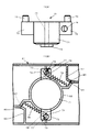
図2はヘッド3の分解斜視図である。
ヘッド3は、連結部5と、払拭体4を挿着する挿着軸体6、7とを有する。挿着軸体6、7は夫々、連結部5の左右の端部にて揺動自在に軸支されている。
FIG. 2 is an exploded perspective view of the
The
連結部5は、底面を開放した略箱形状のケース上部材8とケース底部材14とを合体して全体として略直方体形状に組み立てられ、各種部品の収納空間を形成したケース体を有する。ケース上部材8の上部中央には軸支部材13が一体的に突設されている。軸支部材13のケース体の長手方向の左右近傍には、該収納空間に収納される摺動部材38、39の突出操作部41、42が上方に突出可能な開口85、86が隣接して形成されている。
The connecting
連結部5は、軸支部材13により軸支され、連結管部10の根元部12が連結される連結部材9を有する。連結部材9の上部は筒状に形成され、該筒状の部分の内側には縦長状の突起22(後述の図5参照)が形成されている。根元部12の外径は該筒状の部分の内径より少し大きく、根元部12を該筒状の部分の開口部に挿入することにより、該突起22との接触によって圧接力を受けて、ハンドル2は連結部材9と連結、固着されている。
The connecting
ケース上部材8における根元部12の連結機構を以下に説明する。
軸支部材13の上部には丸型形状の軸受部15が一体的に形成され、軸受部15には該ケース体を横断する横断方向に貫通孔16が穿設されている。連結部材9の下部には、軸受部15に遊嵌される縦溝19が切り込み形成され、縦溝19に直交する方向、つまり該横断方向と同様の向きに貫通孔20が穿設されている。貫通孔20の前後の入口部分にはねじ部材(雄ねじ17と雌ねじ18)の頭部が嵌入可能になるように拡径されている。
The connection mechanism of the
A round-shaped
縦溝19を軸受部15に外嵌した状態で、雄ねじ17をスプリングワッシャ21を介在させて貫通孔16、20を挿通させ雌ねじ18と螺着することにより、連結部材9は該ケース体の長手方向に回動自在に軸支部材13に軸支されている。この軸支によって、連結部材9に連結されたハンドル2を連結部材9の回動方向に動かすことによりヘッド3に対するハンドル2の向きを自在に変更することができる。
In a state where the
図1は掃除具1の使用状態を示す。図3はヘッド3における挿着軸体6、7の垂下状態を示す。図4は使用状態における掃除具1の側面を示す。
挿着軸体6、7は図1に示す使用状態において、夫々、連結部5の左右の端部にて開脚様に横方向に開いた横開き位置から、図3に示す垂下した垂下位置に揺動自在に軸支されている。該使用状態において挿着軸体6、7に払拭体4が挿着されている。払拭体4は、中央部分が開口された長手状の袋部を有した基布と、該基布の表側に多数のパイルが植設されたパイルモップにより構成されている。掃除具1は一対の挿着軸体6、7を略T字形に開いた状態で使用される形体を有する。本発明は単一の挿着軸体を用いて、使用状態において、挿着軸体と、ハンドル又はハンドルに延長して設けられた柄との位置関係をL字形又は略L字形にする形体を備えた掃除具にも適用することができる。
FIG. 1 shows a use state of the cleaning tool 1. FIG. 3 shows a suspended state of the
In the state of use shown in FIG. 1, the
パイル材にはナイロン等の合成繊維や、例えば、木綿等の天然繊維、レーヨン等の再生繊維を使用することができる。本発明においては、パイルモップの他に、払拭体をスポンジ体、ブラシ体、払拭布、払拭紙等により挿着軸体6、7に挿着可能に構成することができる。
As the pile material, synthetic fibers such as nylon, natural fibers such as cotton, and regenerated fibers such as rayon can be used. In the present invention, in addition to the pile mop, the wiping body can be configured to be attachable to the
図5は、挿着軸体6、7が横開き位置に位置した使用状態におけるヘッド3の縦断面を示す。ロック解除時に挿着軸体6、7が垂下位置に位置した状態は同図の2点鎖線で示している。
挿着軸体6、7は細長形状の軸体(揺動部材)により構成され、夫々の一端側に舌片状の揺動支持側端部23、24を有する。揺動支持側端部23、24の各先端側には円板部分を約1/4切り欠いた段差部63、64が形成されている。段差部63、64の近傍には軸孔36が穿設されている。上記ケース体の両端部に挿通させた回動軸25、26を軸孔36にも挿通させることによって挿着軸体6、7は軸支されている。揺動支持側端部23、24より外側に延出された延出部分27、28を払拭体4の袋部に挿入することにより払拭体4は挿着軸体6、7に挿着される。
FIG. 5 shows a longitudinal section of the
The
挿着軸体6、7は夫々、軽量化を図るために延出部分27、28に仕切壁29を介して16個の横孔貫通部30を形成した中空構造を有する。なお、本発明において中空構造に代えて中実構造の挿着軸体を使用することができる。
Each of the
図6の(6A)はケース底部材14の平面図を示す。
ケース底部材14は隔壁で囲まれた空隙部を含む略箱型形状を有し、その両端面部には、揺動支持側端部23、24の揺動を妨げない隙間を形成する凹部34が設けられている。ケース上部材8の両端面部にはケース底部材14の凹部34に対応して、揺動支持側端部23、24の揺動を妨げない隙間を形成する縦溝31が切り欠き形成されている。ケース底部材14の両端部には凹部34の両側にケース底部材14の長手方向と直交する貫通孔33が穿設されている。ケース上部材8の下部両端にはケース底部材14の貫通孔33に対応して、ケース上部材8の長手方向と直交する向きに貫通孔32が穿設されている。
FIG. 6 (6 </ b> A) is a plan view of the
The
ケース上部材8の開放部を下側にしてケース底部材14に被せて冠着した冠着状態において、両端におけるケース上部材8の貫通孔32とケース底部材14の貫通孔33とは互いに連通する。ケース底部材14の4隅には当接規制用突部35が立設されている。該冠着状態において突部35がケース底部材14の裏側に当接した位置で、ケース底部材14はケース上部材8の下側に密着して拘持されて、各種部品を内装し得る内装空間を有したケース体が組み立てられる。
In a crowned state in which the case
該冠着状態において縦溝31と凹部34は互いに重なり合い、この重なり合った隙間に揺動支持側端部23、24を挿入した状態で、貫通孔32、33及び揺動支持側端部23、24の軸孔36に回動軸25、26を挿通させることによって挿着軸体6、7は軸支されている。揺動支持側端部23、24はピン軸材で構成され、抜け止めのために貫通孔32、33及び軸孔36を挿通させた軸端にスプリングリング37を装着して固定されている。
In the crowned state, the
挿着軸体6は図5に示す横開き位置から時計方向(図5の右回転方向)に揺動させても、回動軸25を挟んで揺動支持側端部23と反対側の城辺部分が縦溝31の上側に当接してそれより上側への揺動が規制されている。挿着軸体7は図5に示す横開き位置から反時計方向(図5の左回転方向)に揺動させても、回動軸26を挟んで揺動支持側端部24と反対側の城辺部分が縦溝31の上側に当接してそれより上側への揺動が規制されている。縦溝31と凹部34により形成された隙間と上記の上側揺動規制によって、挿着軸体6、
7は横開き位置から垂下位置までの約90°の範囲で揺動自在になっている。
Even if the
7 is swingable within a range of about 90 ° from the laterally open position to the suspended position.
本発明における横開き位置の開脚状態は、180°の水平に開いた状態に限定されず、180°を超える開脚角度に、あるいは払拭体4が脱落しない範囲で180°未満の開脚角度にした状態にすることができる。
The open leg state at the laterally open position in the present invention is not limited to a horizontally open state of 180 °, and the open leg angle is less than 180 ° at an open leg angle exceeding 180 ° or within a range where the wiping
ヘッド3は挿着軸体6、7を横開き位置にロックするロック機構と、指操作により該ロックを解除する解除機構を有する。
図7はロック機構及び解除機構に用いる、摺動部材38、39と回動部材40の形状を示す。
The
FIG. 7 shows the shapes of the sliding
図7の(7A)〜(7C)は夫々、摺動部材38、39の上面、側面及び底面を示す。図7の(7D)〜(7G)は夫々、回動部材40の上面、側面、底面及び縦断面を示す。(7G)は(7D)のA−A矢視縦断面図である。
(7A) to (7C) in FIG. 7 show the upper surface, the side surface, and the bottom surface of the sliding
ケース上部材8とケース底部材14により組み立てたケース体には、図2に示すように、一対の摺動部材38、39と回動部材40が収容可能になっている。
As shown in FIG. 2, a pair of sliding
摺動部材38、39は、摺動本体部44と、摺動本体部44の上部に突出操作部41、42が立設されている。摺動本体部44はケース底部材14の横幅と同程度の幅を有し、前方片側には前方突出部(内側端部)45を備え、全体として平面視略L字形状を有する。摺動本体部44の裏側で、突出操作部41、42の下側には下方に突出形成した下方突出部(外側端部)46が形成されている。前方突出部45の下側には長穴形状の凹部48が形成されている。摺動本体部44の後方側においては、後部下端を湾曲状に形成した湾曲部47が形成されている。突出操作部41、42は舌片状の指操作体により形成されている。突出操作部41、42には舌片状のものに限らず、指操作が容易な軸体等により形成されてもよい。
The sliding
回動部材40はバネ43を縦方向に収容する筒体49により構成されている。バネ43には図2に示すように、バネ線材の両端部を開放突出させたコイルバネを使用している。バネ43は、該両端部が一側面方向に上下に延出された、上側開放端部54、下側開放端部55を備える。筒体49の上側には一対の突出部50が側面外側に突出形成されている。一対の突出部50は互いに直径方向に対峙して配設されている。突出部50の上面には円柱形状の筒体係合部51が筒体49上面より突出して形成されている。筒体係合部51は長穴形状の凹部48に嵌入され、該長穴形状に沿って摺動可能な外径を有する。
The rotating
筒体49の下面側には断面リング状のバネ収容凹部52が形成されている。突出部50の下方で、筒体49の側面には、バネ43の上側開放端部54を遊挿可能にする縦スリット53が切り欠き形成されている。図7の(7E)に示すように、筒体49及び突出部50を縦方向に切断した縦切断面は縦スリット53も半分に縦割り状に切断する。即ち、上方より視認したときに、突出部50と縦スリット53は筒体49の直径方向に沿って同一線上に並んでいる。筒体49の中央下部59はバネ収容凹部52より約1.5mm突出している。筒体49の中心には中心貫通孔60が鉛直方向に貫通形成されている。
A
ケース底部材14の中央には、図6の(6A)に示すように、隔壁57で囲むようにして、回動部材40を収容するための円筒形状の凹状座部56が形成されている。凹状座部56の中心には凸部61が突設されている。中心貫通孔60に凸部61を嵌入させることにより、回動部材40の筒体49は凹状座部56内に安定して載置される。
In the center of the
隔壁57のうち、ケース底部材14の長手方向側に位置する隔壁62には、バネ43の
下側開放端部55を挿入可能にする縦スリット58が切り欠き形成されている。縦スリット58はケース底部材14の底面に達するスリット長を有する。
A
バネ43は、上側開放端部54を縦スリット53に挿入して外側に延出させた状態で、縦長状にしてバネ収容凹部52に収容される。このバネ収容状態で中央下部59を下側にして、下側開放端部55を縦スリット58に挿入させて回動部材40は凹状座部56内に嵌入、載置されている。回動部材40の中央下部59をバネ収容凹部52底部に載置した状態においては、バネ43は、上側開放端部54が縦スリット53を挿通し、下側開放端部55が縦スリット58を挿通した状態でバネ収容凹部52と凹状座部56の間に静置される。
The
図8は挿着軸体7を横開き位置にロックしたロック状態における部分拡大縦断面を示す。図9は挿着軸体7のロックを解除したロック解除状態における部分拡大縦断面を示す。
FIG. 8 shows a partially enlarged longitudinal section in a locked state in which the
図8及び図9に示すように、隔壁62の高さはバネ収容凹部52の深さ、即ち、縦スリット58よりも短くなっている。このため、バネ43の上側開放端部54は隔壁62に接触することなく縦スリット53より延出可能になっている。
As shown in FIGS. 8 and 9, the height of the
ケース上部材8とケース底部材14によるケース体に、摺動部材38、39及び回動部材40を組み込んでヘッド3を組み立てる手順を以下に説明する。
図6の(6B)と(6C)は夫々、挿着軸体6、7のロック状態における該ケース体の水平断面、ロック解除状態における該ケース体の水平断面を示す。
A procedure for assembling the
6B and 6C respectively show a horizontal section of the case body in the locked state of the
回動部材40を凹状座部56内に嵌入、載置した状態において、バネ収容凹部52に収容されたバネ43の下側開放端部55は縦スリット58に挿入されているため、バネ43に捻じれ力を加えても縦スリット58に引っ掛って自由に動かない状態になっている。上側開放端部54は縦スリット58に挿入されていず、筒体49の縦スリット53に引っ掛かっているだけであるので、バネ43に捻じれ力を加えると筒体49とともに捻じり変位が可能になっている。回動部材40を凹状座部56に静置した状態においては、2つの突出部50がケース体の中心線C上に並んでいる。この静置状態から、突出部50を手で摘むなどして内側に引き寄せて、バネ43に捻じり力を加えるように90°回転させ、突出操作部41、42を上側にして、前方突出部45の凹部48を各突出部50に嵌め込むようにして摺動部材38、39をケース底部材14上に載置しておく。図6の(6B)と(6C)に示すように、摺動部材38、39は、凹状座部56を中央にして点対称にケース体内に収納されている。
Since the lower
ついで、突出操作部41、42を開口85、86からハンドル自由端側に突出させて、ケース上部材8をケース底部材14に被せて冠着する。該冠着状態において貫通孔32、33及び軸孔36に回動軸25、26を挿通させることによって挿着軸体6、7を軸支するとともに、ケース上部材8とケース底部材14を合体させて、摺動部材38、39及び回動部材40を組み込んだケース体が組み立てられる。開口85、86の長手方向の夫々の開口長さは、段差部63、64と当接したロック状態を解除し得る範囲において、突出操作部が摺動可能な長さになっている。突出操作部41、42を互いに接近するように内向きに移動させて挿着軸体6、7を垂下させた状態においては、(6C)の水平断面に示すように、2つの突出部50は中心線Cを挟んで直交した位置関係にある。(6C)の場合、バネ43は上面視、反時計方向に捻じられているので、該捻じりによるバネ43の復元力(付勢力)が時計方向に生じている。
Next, the projecting
上記構成のヘッド3において、バネ43の付勢力を摺動部材38、39に伝達するための枢支機構が回動部材40の突出部50と摺動部材38、39の凹部48によって形成さ
れている。該枢支機構により、回動部材40の時計方向の復元運動に連動して摺動部材38、39を夫々、ケース体の左右端側に摺動、移動させることができる。
In the
図9は挿着軸体6、7のロックを解除する際に突出操作部42を開口86の軸支部材13側に引き寄せたときの軸支部分の断面構造を示す。
FIG. 9 shows a cross-sectional structure of the shaft support portion when the projecting
該軸支部分におけるケース体端部の下面側には、揺動支持側端部24の揺動を妨げない揺動可能空間が形成されている。ケース上部材8の端部裏側には段差部64に当接する係止部65が形成されている。指操作により突出操作部42を開口86の軸支部材13側に引き寄せたときには、回動軸26を回動中心にして回転する揺動支持側端部24の先端軌跡円R2より半径の大きい軌跡円R1の揺動可能空間を形成するように、摺動部材39の湾曲部47が軸支部材13側に退避可能になっている。突出操作部42を開口86の軸支部材13側に引き寄せる力を取り除くと、バネ43の付勢力を受けて下方突出部46は右端側に摺動可能になっている。
A swingable space that does not hinder the swing of the swing
挿着軸体6、7を図3の垂下位置から横開き位置に回動させるとき、段差部63、64に近接した揺動支持側端部23、24の先端面が突出操作部41、42の湾曲部47の湾曲面に当接しながら横開き位置(ロック位置)に移動し、ついで段差部63、64の当接面が突出操作部41、42の下方突出部46の下面に当接してロック状態(後述の図8参照)に移行可能になっている。突出操作部41、42と揺動支持側端部23、24との当接機構は一種のカム機構として働く。即ち、挿着軸体6、7の垂下状態(ロック解除状態)では、突出操作部41、42はバネ43の付勢力を受けて軸支部材13より外向きに付勢されているので、挿着軸体6、7の上記回動動作時には湾曲部47の湾曲面における接触によって突出操作部41、42は軸支部材13より内向きに移動する力の作用を受けて内向きに移動し、ロック位置にてその内向き作用がなくなって再び外向きに移動して、段差部63、64の当接面が下方突出部46の下面に当接するロック状態に移行可能になる。
When the
図9に示す湾曲部47の退避状態においては挿着軸体7は時計方向で、段差部64が係止部65に当接するまで回動可能になっている。係止部65との当接位置では挿着軸体7に挿着された払拭体4の袋部が自重により落下して外れ得る垂下位置に相当する。本実施形態においては係止部65を挿着軸体7の垂下方向が鉛直方向になる位置に形成しているが、本発明においては、払拭体4の袋部が自重により外れ得る位置に該係止部を設けることができる。挿着軸体6の開口85側においても左右対称にして図9の断面構造と同様の断面構造になっている。
In the retracted state of the bending
ヘッド3は、バネ43の前記両端部54、55を夫々、連結部5の縦スリット58と筒体49の縦スリット53に係止して、所定捻じり方向にバネ43によって筒体49を付勢し、摺動部材38、39の内側端部(前方突出部45)は摺動部材係合部として筒体係合部51と枢支した枢支機構を有する。ヘッド3は、図6の(6B)に示す横開き位置において、揺動支持端部24、25の段差部63、64と、摺動部材38、39の外側端部(下方突出部46)とを当接、係合させて挿着軸体6、7を横開き位置にロックするロック機構を有する。
The
図8は挿着軸体7を図9の垂下状態から反時計方向に回動させて横開き位置に移動させたときの軸支部分の断面構造を示す。挿着軸体6側においても左右対称にして図8の断面構造と同様の断面構造になっている。
FIG. 8 shows a cross-sectional structure of the shaft support portion when the
バネ43の付勢力を摺動部材38、39に伝達するための該枢支機構が回動部材40の突出部50と摺動部材38、39の凹部48によって形成されているので、該枢支機構に
より、回動部材40の復元運動に連動して摺動部材38、39を夫々、ケース体の左右端側に摺動、移動させることができる。挿着軸体7を図9に示す垂下状態から反時計方向に回動させて横開き位置に移動させたとき、バネ43の付勢力を該枢支機構を介して外側端部(下方突出部46)に伝達し摺動部材38、39を外向きに付勢して該ロック機構によるロック状態を保持することができる。払拭体4を脱離させる際には、突出操作部41、42をバネ付勢力に抗して操作して摺動部材38、39を内向きに摺動することにより該ロック状態を解除して挿着軸体6、7を垂下位置側に揺動させることができる。
The pivot mechanism for transmitting the biasing force of the
ヘッド3は、上記の枢支機構、ロック機構及びロック解除機構を備えるので、挿着軸体6、7が揺動する揺動平面(図9の軌跡円R2を含む平面)に対して直交する平面上を摺動部材38、39が左右に摺動可能になっており、連結部5の上側の開口85、86より突出操作部41、42を突出させて指操作が可能になっている。
Since the
上記構成により、清掃具1は、ハンドル2の根元部12に連結される連結部5と、払拭体4を挿着可能にした挿着軸体6,7とを備え、連結部5の端部に、横方向に開いた横開き位置から垂下した垂下位置に揺動可能に払拭体4を取り付けた清掃具であって、バネ43によって付勢されて鉛直方向に沿った回動軸を中心にして連結部5内に回動可能に収設された回動部材40と、水平軸方向に沿って摺動可能に前記連結部5内に設けた摺動部材38、39と、連結部5の上部に設けた開口85、86より突出して配設され、摺動部材38、39に設けた突出操作部41、42と、摺動部材38、39の摺動方向の内側端部(前方突出部45)と回動部材40とを枢支する枢支機構と、横開き位置において挿着軸体6、7の揺動支持側端部23、24と摺動部材38、39の摺動方向の外側端部(下方突出部46)とを係合させて挿着軸体6、7を横開き位置にロックするロック機構とを有し、バネ43の付勢力を枢支機構を介して内側端部45に伝達し摺動部材38、39を外向きに付勢してロック機構によるロック状態を保持し、突出操作部41、42を付勢力に抗して操作して摺動部材38、39を内向きに摺動することによりロック状態を解除して挿着軸体6、7を垂下位置側に揺動可能にすることができる。
With the above configuration, the cleaning tool 1 includes the connecting
掃除具1によれば、連結部5からハンドル自由端側に突出した突出操作部41、42の操作により挿着軸体6、7が連結部5に対して揺動可能となることによって払拭体4を各挿着軸体から脱離させることができるので、払拭体4の取付状態において清掃作業者に視認しやすい連結部5の上側に突出操作部41、42を操作容易に配置して、払拭体4の脱離のための取外し操作を簡便に行うことができる。
According to the cleaning tool 1, the
本実施形態に係るヘッド3においては、各突出操作部と連結して一対の突出操作部41、42を連動させる連動手段が上記の枢支機構により構成され、片方の突出操作部の動作が該連動手段を介して他方の突出操作部と連動させることができるので、片方の突出操作部を操作することにより複数の挿着軸体6、7が連動して揺動して払拭体4の取外し操作を簡便に行うことができる。
In the
筒体49を含む回動部材40を用いて構成された該連動手段において、筒体49は円筒状回動部として回動動作し、筒体49の上部外周に設けた一対の突出部50の上面に形設された筒体係合部51は連動突起として突出操作部との連動作用に供されるので、本実施形態においては、複数の突出操作部の連動機構を設置スペースを大型にすることなく連結部5内にコンパクトに収設できて簡易且つ安価に構成することができる。本発明においては、前記連動突起を、回動可能な軸部の回動中心から離れた位置の軸部上面に形設してもよく、この場合にも、該連動機構を設置スペースを大型にすることなく簡易且つ安価に構成することができる。
In the interlocking means configured using the rotating
本発明の第5の形態によれば、前記連動手段は円筒状回動部を有し、前記円筒状回動部
の上部外周に前記連動突起を設け、前記突出操作部の一端に前記連動突起を連動させる長孔を設けたので、前記複数の突出操作部の連動機構を設置スペースを大型にすることなく簡易且つ安価に構成して、払拭体の取外し操作を簡便に行える掃除具を実現することができる。
特に、掃除具1においては、例えば、家具と床面の隙間にハンドル2を寝かせるように傾けて挿し入れて掃除するときにヘッド3を左右前後に振り動かしたりしても、突出操作部42はハンドル2を把持した作業者側に向くので、家具の脚部等に誤って当たって清掃作業中に払拭体4を離脱させてしまうトラブルを生ずることなく円滑な清掃作業を行うことができる。
According to a fifth aspect of the present invention, the interlocking means has a cylindrical rotating part, the interlocking protrusion is provided on the outer periphery of the upper part of the cylindrical rotating part, and the interlocking protrusion is provided at one end of the protruding operation part. Since a long hole is provided for interlocking with each other, the interlocking mechanism of the plurality of projecting operation portions is configured simply and inexpensively without increasing the installation space, thereby realizing a cleaning tool that can easily perform the operation of removing the wiping body. be able to.
In particular, in the cleaning tool 1, for example, even when the
更に、掃除具1はヘッド3に上記の枢支機構、ロック機構及びロック解除機構を備えることによって、清掃作業時に家具や什器などに触れないように連結部5の上側にて突出操作部41、42を突設させ、清掃作業を妨げることなく、払拭体の挿着状態を安定に保持でき、しかも連結部5の上側にて該突出操作部を操作して簡易に該ロックの解除を行え、払拭体4を簡単なワンタッチ操作で脱離することできる。特に、枢支機構はコイルバネと筒体49を用いた簡単な付勢力伝達構造であるので、安価に構成できるうえ、払拭体4の挿着状態を安定に保持することができる。
Furthermore, the cleaning tool 1 is provided with the above-mentioned pivot support mechanism, lock mechanism, and lock release mechanism in the
ロック機構においては、横開き位置において段差部63、64が外側端部に当接して摺動部材38、39と挿着軸体6、7をロック状態にするので、安定かつ確実にロック状態を保持でき、しかも簡便な操作によってワンタッチで該ロックの解除が可能になる。特に摺動部材38、39を摺動可能に該ケース体に収設し、ロック状態を解除し得る範囲で突出操作部41、42が摺動可能な長さに開口85、86をケース体上面に形成したので、該ケース体に枢支機構及びロック機構をコンパクトに収納でき、該開口より突出した突出操作部41、42を操作してワンタッチで該ロックの解除を行うことができる。
In the locking mechanism, the stepped
前記実施形態においては、上記の枢支機構によって、筒体49内に縦方向に収容したコイルバネの捻じり付勢力を摺動部材38、39に伝達しているが、本発明の付勢力発生源としては該コイルバネによるものに限定されない。
In the above embodiment, the torsional biasing force of the coil spring accommodated in the longitudinal direction in the
図10は付勢力発生源の別の実施例を示す。図10の(10A)は回動部材40と同様に枢支機構を構成する回動部材70の側面を示す。同図(10B)はケース底部材81に回動部材70を装着した平面状態を示す。ケース底部材81はケース底部材14と同様にケース体を構成する部材である。なお、この実施例では図10に示す部材以外は前記実施形態と同様の構成とする。
FIG. 10 shows another embodiment of the urging force source. (10A) of FIG. 10 shows the side surface of the
回動部材70は、回動部材40と異なり、バネを縦方向に収容しない円柱体の本体部71を有する。本体部71の下部は回動部材40の中央下部59と同様の突出部74が設けられている。本体部71には中心貫通孔60と同様の中心貫通孔75が穿設されている。ケース底部材81中央には、前記実施形態と同様に、隔壁82により形成された凹状座部が形成されている。該凹状座部の中心には凸部61と同様の凸部(図示せず)が設けられていて、突出部74を下向きにして該凸部を中心貫通孔75に嵌入することにより、回動部材70は該凹状座部に安定して載置される。
Unlike the
本体部71の上側には一対の外延部72が側面外側に突出形成されている。一対の突出部72は互いに本体部71の直径方向に対峙して配設されている。外延部72の上面には回動部材40の筒体係合部51と同様に、円柱形係合部73が突出形成されている。外延部72の側面側には、本体部71側面の接面方向に横穴状に穿設された穴部76が形成されている。穴部76には圧縮コイルバネ78の一端側が挿入される。穴部76の奥部には圧縮コイルバネ78の端部79を挿入するための貫通孔77が貫通形成されている。
On the upper side of the
ケース底部材81内部には、隔壁82と繋がった隔壁83が形成されている。一対の隔壁83が隔壁82によって形成された凹状座部を中心にして点対称状に配設されている。隔壁83には圧縮コイルバネ78のもう一方の端部80を挿入するための貫通孔84が貫通形成されている。圧縮コイルバネ78は両方の端部79、80を夫々、貫通孔77、84に引っ掛けた状態で装着されている。
A
(10B)は前記実施形態における図6の(6C)と同様に、挿着軸体6、7を開脚状にロックしたロック状態を解除したロック解除状態を示す。一対の外延部72の夫々に対して設けた、一対の圧縮コイルバネ78が回動部材70を時計方向に回動させる向きに、弾性付勢力を発生させる付勢力発生源となっている。圧縮コイルバネ78は(10B)のロック解除状態から、90°以下の所定回動角度で時計方向に回動して挿着軸体6、7のロック状態に移行し得るバネ弾性力を有する。本実施例における摺動部材は、圧縮コイルバネ78のバネ弾性力を受けて、摺動部材38、39と同様にロック位置まで摺動し得る大きさを有する。隔壁82、隔壁83は回動部材70の回動を妨げないように、回動時に外延部72が衝突しない高さに低く形成されている。
(10B) shows the unlocked state in which the locked state in which the
図10の実施例によれば、筒体49内に縦方向に収容したコイルバネに代えて、圧縮コイルバネ78による付勢力発生源で発生された付勢力によって、前記実施形態と同様に、挿着軸体6、7を揺動させる揺動平面に対して直交する平面上を摺動部材を摺動させて突出操作部41、42のロック解除操作を可能にすることができる。
According to the embodiment of FIG. 10, instead of the coil spring housed in the longitudinal direction in the
尚、本発明は上記実施形態に限定されるものではなく、本発明の技術的思想を逸脱しない範囲における種々変形例、設計変更などをその技術的範囲内に包含するものであることは云うまでもない。 It should be noted that the present invention is not limited to the above-described embodiment, and various modifications, design changes and the like within the scope not departing from the technical idea of the present invention are included in the technical scope. Nor.
本発明は、パイルモップ等の払拭体の取替を簡便に行え、円滑な清掃作業を行える掃除具を提供することができる。本発明に係る掃除具は、例えば、モップレンタル製品を取り扱うダストコントロール業界など多くの業界に利用できるものである。 The present invention can provide a cleaning tool that can easily replace a wiping body such as a pile mop and perform a smooth cleaning operation. The cleaning tool according to the present invention can be used in many industries such as the dust control industry that handles mop rental products.
1 掃除具
2 ハンドル
3 払拭体取付用ヘッド
4 払拭体
5 連結部
6 挿着軸体
7 挿着軸体
8 ケース上部材
9 連結部材
10 連結管部
11 グリップ部
12 根元部
13 軸支部材
14 ケース底部材
15 軸受部
16 貫通孔
17 雄ねじ
18 雌ねじ
19 縦溝
20 貫通孔
21 スプリングワッシャ
22 突起
23 揺動支持側端部
24 揺動支持側端部
25 回動軸
26 回動軸
27 延出部分
28 延出部分
29 仕切壁
30 横孔貫通部
31 縦溝
32 貫通孔
33 貫通孔
34 凹部
35 当接規制用突部
36 軸孔
37 スプリングリング
38 摺動部材
39 摺動部材
40 回動部材
41 突出操作部
42 突出操作部
43 バネ
44 摺動本体部
45 前方突出部
46 下方突出部
47 湾曲部
48 凹部
49 筒体
50 突出部
51 筒体係合部
52 バネ収容凹部
53 縦スリット
54 上側開放端部
55 下側開放端部
56 凹状座部
57 隔壁
58 縦スリット
59 中央下部
60 中心貫通孔
61 凸部
62 隔壁
63 段差部
64 段差部
65 係止部
70 回動部材
71 本体部
72 外延部
73 円柱形係合部
74 突出部
75 中心貫通孔
76 穴部
77 貫通孔
78 圧縮コイルバネ
79 端部
80 端部
81 ケース底部材
82 隔壁
83 隔壁
84 貫通孔
85 開口
86 開口
DESCRIPTION OF SYMBOLS 1 Cleaning tool 2 Handle 3 Wiping body attachment head 4 Wiping body 5 Connection part 6 Insertion shaft body 7 Insertion shaft body 8 Case upper member 9 Connection member 10 Connection pipe part 11 Grip part 12 Root part 13 Axis support member 14 Case Bottom member 15 Bearing portion 16 Through hole 17 Male screw 18 Female screw 19 Vertical groove 20 Through hole 21 Spring washer 22 Projection 23 Swing support side end 24 Swing support side end 25 Turning shaft 26 Turning shaft 27 Extending portion 28 Extension part 29 Partition wall 30 Horizontal hole penetrating part 31 Vertical groove 32 Through hole 33 Through hole 34 Recess 35 Contact protrusion 36 Shaft hole 37 Spring ring 38 Sliding member 39 Sliding member 40 Rotating member 41 Projection operation Part 42 projecting operation part 43 spring 44 sliding body part 45 front projecting part 46 downward projecting part 47 bending part 48 recessed part 49 cylindrical body 50 projecting part 51 cylindrical body engagement 52 Spring accommodating recess 53 Vertical slit 54 Upper open end 55 Lower open end 56 Concave seat 57 Bulkhead 58 Vertical slit 59 Central lower part 60 Center through hole 61 Convex part 62 Bulkhead 63 Step part 64 Step part 65 Locking part 70 Rotating member 71 Main body portion 72 Outer extension portion 73 Columnar engagement portion 74 Projection portion 75 Center through hole 76 Hole portion 77 Through hole 78 Compression coil spring 79 End portion 80 End portion 81 Case bottom member 82 Partition wall 83 Partition wall 84 Through hole 85 Opening 86 opening
Claims (4)
前記挿着軸体及び前記突出操作部をそれぞれ複数設け、各突出操作部と連結して複数の突出操作部を連動させる連動手段を有し、片方の突出操作部の動作が前記連動手段を介して他方の突出操作部と連動することを特徴とする清掃具。 A connecting portion connected to a handle or a base portion of a handle provided to extend from the handle; and an insertion shaft extending from the connection; and inserting the insertion shaft into the wiping body The cleaning tool is provided with a protruding operation part protruding from the connection part toward the handle free end side, and the insertion shaft body can swing relative to the connection part by operating the protrusion operation part. By making the wiping body detachable from the insertion shaft body,
A plurality of the insertion shaft bodies and the plurality of projecting operation parts are provided, and interlocking means for interlocking the plurality of projecting operation parts by being connected to each projecting operation part, and the operation of one projecting operation part via the interlocking means. A cleaning tool that is interlocked with the other protruding operation portion .
Priority Applications (1)
| Application Number | Priority Date | Filing Date | Title |
|---|---|---|---|
| JP2015025457A JP5827765B1 (en) | 2015-02-12 | 2015-02-12 | Cleaning tool |
Applications Claiming Priority (1)
| Application Number | Priority Date | Filing Date | Title |
|---|---|---|---|
| JP2015025457A JP5827765B1 (en) | 2015-02-12 | 2015-02-12 | Cleaning tool |
Publications (2)
| Publication Number | Publication Date |
|---|---|
| JP5827765B1 true JP5827765B1 (en) | 2015-12-02 |
| JP2016146938A JP2016146938A (en) | 2016-08-18 |
Family
ID=54776818
Family Applications (1)
| Application Number | Title | Priority Date | Filing Date |
|---|---|---|---|
| JP2015025457A Active JP5827765B1 (en) | 2015-02-12 | 2015-02-12 | Cleaning tool |
Country Status (1)
| Country | Link |
|---|---|
| JP (1) | JP5827765B1 (en) |
Families Citing this family (3)
| Publication number | Priority date | Publication date | Assignee | Title |
|---|---|---|---|---|
| JP7022569B2 (en) * | 2017-11-13 | 2022-02-18 | シャープ株式会社 | Vacuum cleaner |
| TWI657783B (en) * | 2018-06-25 | 2019-05-01 | 丁明哲 | Folding flat mop |
| CN110623611B (en) * | 2018-06-25 | 2021-03-12 | 丁明哲 | Folding flat mop |
Citations (1)
| Publication number | Priority date | Publication date | Assignee | Title |
|---|---|---|---|---|
| JP2600863Y2 (en) * | 1992-12-16 | 1999-10-25 | 幸男 中田 | Installation equipment for elephant cloth in mop |
-
2015
- 2015-02-12 JP JP2015025457A patent/JP5827765B1/en active Active
Patent Citations (1)
| Publication number | Priority date | Publication date | Assignee | Title |
|---|---|---|---|---|
| JP2600863Y2 (en) * | 1992-12-16 | 1999-10-25 | 幸男 中田 | Installation equipment for elephant cloth in mop |
Also Published As
| Publication number | Publication date |
|---|---|
| JP2016146938A (en) | 2016-08-18 |
Similar Documents
| Publication | Publication Date | Title |
|---|---|---|
| JP5827765B1 (en) | Cleaning tool | |
| US20050102781A1 (en) | Holding device and cleaning tool with the holding device | |
| JP6129811B2 (en) | Electric vacuum cleaner | |
| JP2011224224A (en) | Electric vacuum cleaner | |
| JP2004209223A (en) | Extension tube locking device of vacuum cleaner | |
| JP2011250980A (en) | Cleaning tool with turnable wiper-inserted portion | |
| US9186789B2 (en) | Operating rod assembly for a toolbox | |
| JPWO2018061580A1 (en) | REMOVING DEVICE HAVING LOCK MECHANISM AND HINGE DEVICE USING THE SAME | |
| JP5281061B2 (en) | Caster and caster unit | |
| JP2002177186A (en) | Mop grip tool with handle | |
| JP2017038854A (en) | One-side depressing button type wiping body holding tool and cleaning tool | |
| JP4030681B2 (en) | mop | |
| JP7334999B2 (en) | stick cleaning tool | |
| JP4578300B2 (en) | Cleaning member holder | |
| JP2014040845A (en) | Lock mechanism of rotary body | |
| JP4228227B2 (en) | Electric vacuum cleaner | |
| JP2014087684A (en) | Vacuum cleaner | |
| JP5279335B2 (en) | Cylinder lock | |
| JP4869902B2 (en) | Cleaning tool | |
| JP5818606B2 (en) | Wiping body holder, wiping body and cleaning tool | |
| JPH0532439Y2 (en) | ||
| CN214595612U (en) | Foldable handle and cooker | |
| JP6016621B2 (en) | Cleaning tool joint structure | |
| JP4093945B2 (en) | Locking device for opening and closing body | |
| JP7525890B2 (en) | Caster device |
Legal Events
| Date | Code | Title | Description |
|---|---|---|---|
| TRDD | Decision of grant or rejection written | ||
| A01 | Written decision to grant a patent or to grant a registration (utility model) |
Free format text: JAPANESE INTERMEDIATE CODE: A01 Effective date: 20150929 |
|
| A61 | First payment of annual fees (during grant procedure) |
Free format text: JAPANESE INTERMEDIATE CODE: A61 Effective date: 20151016 |
|
| R150 | Certificate of patent or registration of utility model |
Ref document number: 5827765 Country of ref document: JP Free format text: JAPANESE INTERMEDIATE CODE: R150 |
|
| R250 | Receipt of annual fees |
Free format text: JAPANESE INTERMEDIATE CODE: R250 |
|
| R250 | Receipt of annual fees |
Free format text: JAPANESE INTERMEDIATE CODE: R250 |
|
| R250 | Receipt of annual fees |
Free format text: JAPANESE INTERMEDIATE CODE: R250 |