JP5808160B2 - Electronic component mounting equipment - Google Patents
Electronic component mounting equipment Download PDFInfo
- Publication number
- JP5808160B2 JP5808160B2 JP2011133816A JP2011133816A JP5808160B2 JP 5808160 B2 JP5808160 B2 JP 5808160B2 JP 2011133816 A JP2011133816 A JP 2011133816A JP 2011133816 A JP2011133816 A JP 2011133816A JP 5808160 B2 JP5808160 B2 JP 5808160B2
- Authority
- JP
- Japan
- Prior art keywords
- component
- dummy
- electronic component
- regular
- electronic
- Prior art date
- Legal status (The legal status is an assumption and is not a legal conclusion. Google has not performed a legal analysis and makes no representation as to the accuracy of the status listed.)
- Active
Links
- 230000007423 decrease Effects 0.000 claims description 6
- 239000000758 substrate Substances 0.000 claims description 6
- 238000000034 method Methods 0.000 claims description 4
- 230000004308 accommodation Effects 0.000 description 9
- 238000004519 manufacturing process Methods 0.000 description 8
- 238000000605 extraction Methods 0.000 description 6
- 230000004397 blinking Effects 0.000 description 2
- 238000011084 recovery Methods 0.000 description 2
- 239000003086 colorant Substances 0.000 description 1
- 230000002950 deficient Effects 0.000 description 1
- 238000010586 diagram Methods 0.000 description 1
- 230000005284 excitation Effects 0.000 description 1
- 230000005484 gravity Effects 0.000 description 1
- 238000003384 imaging method Methods 0.000 description 1
- 238000012986 modification Methods 0.000 description 1
- 230000004048 modification Effects 0.000 description 1
Images


Landscapes
- Supply And Installment Of Electrical Components (AREA)
Description
本発明は、バルクフィーダを備え、バルクフィーダによって供給された電子部品を、基板に実装する電子部品実装装置に関するものである。 The present invention relates to an electronic component mounting apparatus that includes a bulk feeder and mounts an electronic component supplied by the bulk feeder on a substrate.
一般にバルクフィーダを備えた電子部品実装装置においては、バルクフィーダのカセット内に電子部品がバルク状に収容され、振動、加圧エア等の適宜搬送手段によって部品供給路を整列されながら搬送され、所定位置に供給されるようになっている。従来、バルクフィーダを備えた電子部品実装装置として、例えば、特許文献1に記載されたものが知られている。 Generally, in an electronic component mounting apparatus equipped with a bulk feeder, electronic components are accommodated in a bulk shape in a cassette of the bulk feeder, and are conveyed while being aligned in a component supply path by appropriate conveying means such as vibration and pressurized air. Is supplied to the position. 2. Description of the Related Art Conventionally, as an electronic component mounting apparatus provided with a bulk feeder, for example, one described in Patent Document 1 is known.
この種の電子部品実装装置においては、時として、カセット内に収容された電子部品を最後まで使い切るように、予定された生産枚数に対してぎりぎりの個数の電子部品しか収容されない場合がある。 In this type of electronic component mounting apparatus, sometimes there are cases where only a marginal number of electronic components are accommodated with respect to the planned production number so that the electronic components accommodated in the cassette are used up to the end.
例えば、ある基板種の生産予定枚数に対し、生産に必要である部品数にあるマージンを加えた数の部品が収容されたカセットを準備したり、あるいは基板生産を依頼した顧客からは前記必要数が収容されたカセットを支給される場合が多い。また、これら同一基板種を生産する際、使用する同一部品は、規格が同じものを使用することは勿論のこと、同一メーカー製であり、かつ同じロットものを使用することがトレーサビリティの観点からも望まれている。 For example, for a planned production quantity of a certain board type, a cassette containing the number of parts required for production plus a margin is prepared, or the required number is received from a customer who has requested board production. Are often provided with cassettes that are stored. In addition, when producing these same board types, the same parts used are of the same standard as well as the same manufacturer, and the same lots are also used from the viewpoint of traceability. It is desired.
しかしながら、バルクフィーダの特性上、バルクフィーダから電子部品を供給する際に、カセット内に残存する電子部品の数が少なくなると、電子部品を部品供給路に円滑に送ることができなくなる場合がある。部品の在庫が大量にある場合には、バルクフィーダに電子部品を補給すればよいが、上記したように予定生産枚数に対して部品数がぎりぎりの場合には、送りの停滞によって生産を継続できなく恐れがあり、電子部品を最後まで使い切ることができなくなる。 However, due to the characteristics of the bulk feeder, when supplying electronic components from the bulk feeder, if the number of electronic components remaining in the cassette decreases, the electronic components may not be smoothly fed to the component supply path. If there is a large amount of parts in stock, it is sufficient to supply electronic parts to the bulk feeder.However, as described above, if the number of parts is marginal to the planned production quantity, production can be continued due to the stagnation of the feed. There is a fear that the electronic components cannot be used up to the end.
本発明は、カセット内へのダミー部品の補給によって、バルクフィーダにおける部品送りを円滑に行えるようにし、正規の電子部品を使い切ることを可能にした電子部品実装装置を提供することを目的とするものである。 SUMMARY OF THE INVENTION An object of the present invention is to provide an electronic component mounting apparatus that enables smooth feeding of components in a bulk feeder by supplying dummy components into a cassette, and allows regular electronic components to be used up. It is.
上記の課題を解決するため、請求項1に係る発明の特徴は、カセット内に収容された電子部品およびダミー部品を部品供給路に整列させるとともに部品取出位置に供給するバルクフィーダを備え、該バルクフィーダによって前記部品供給路に供給された電子部品を、部品実装ヘッドに設けた吸着ノズルにより吸着して、基板に実装する電子部品実装装置において、前記バルクフィーダの前記カセット内にダミー部品を要求する案内を出す案内手段と、前記吸着ノズルによって前記部品取出位置より吸着された部品が正規の電子部品であるかダミー部品であるかを判別する判別手段と、該判別手段によって、正規の電子部品と判別された場合にのみ、当該電子部品を基板に実装する実装制御手段とを有することである。 In order to solve the above-mentioned problem, a feature of the invention according to claim 1 is that the electronic component and the dummy component accommodated in the cassette are arranged in the component supply path and are provided with a bulk feeder for supplying the component to the component extraction position. In the electronic component mounting apparatus that mounts the electronic component supplied to the component supply path by the feeder with a suction nozzle provided on the component mounting head, and requests the dummy component in the cassette of the bulk feeder. Guiding means for giving guidance, discriminating means for discriminating whether the component sucked from the component pick-up position by the suction nozzle is a regular electronic component or a dummy component, and the discriminating means Only when it is determined, it has a mounting control means for mounting the electronic component on the board.
請求項2に係る発明の特徴は、請求項1において、前記案内手段は、前記バルクフィーダの前記カセット内に残存する正規の電子部品の数が少なくなったことに基づいて、ダミー部品の補給を要求するようになっていることである。 The invention according to claim 2 is characterized in that, in claim 1, the guide means replenishes dummy parts based on a decrease in the number of regular electronic parts remaining in the cassette of the bulk feeder. It is to come to demand.
請求項3に係る発明の特徴は、請求項1または請求項2において、前記判別手段によってダミー部品と判別された場合には、当該ダミー部品を回収部に回収するようになっていることである。 A feature of the invention according to claim 3 is that in claim 1 or claim 2, when the discriminating means discriminates a dummy part, the dummy part is collected in the collecting unit. .
請求項4に係る発明の特徴は、請求項1ないし請求項3のいずれか1項において、前記ダミー部品は、正規の電子部品に対して色もしくは形状を異にし、正規の電子部品かダミー部品かの判別を、画像処理によって行うことである。 According to a fourth aspect of the present invention, in any one of the first to third aspects, the dummy component is different in color or shape from a regular electronic component, and is a regular electronic component or a dummy component. This determination is performed by image processing.
請求項5に係る発明の特徴は、請求項1ないし請求項4のいずれか1項において、前記バルクフィーダは、振動およびエアの少なくとも1つの作用によって電子部品を前記部品供給路に供給するようになっていることである。 According to a fifth aspect of the present invention, in any one of the first to fourth aspects, the bulk feeder supplies the electronic component to the component supply path by at least one action of vibration and air. It is that.
上記のように構成した請求項1に係る発明によれば、バルクフィーダのカセット内にダミー部品を要求する案内を出す案内手段と、吸着ノズルによって部品取出位置より吸着された部品が正規の電子部品であるかダミー部品であるかを判別する判別手段と、判別手段によって、正規の電子部品と判別された場合にのみ、当該電子部品を基板に実装する実装制御手段とを有するので、バルクフィーダの部品収容カセット内へのダミー部品の補給によって、部品収容カセット内の部品を部品供給路に円滑に送ることができるようになる。
According to the invention according to claim 1 configured as described above, the guide means for issuing a guide requesting a dummy part in the cassette of the bulk feeder, and the part sucked from the part picking position by the suction nozzle are regular electronic parts. And a dummy control part, and a mounting control means for mounting the electronic component on the substrate only when the determination means determines that the electronic component is a regular electronic component. By supplying the dummy parts to the component storage cassette, the components in the component storage cassette can be smoothly sent to the component supply path.
請求項2に係る発明によれば、案内手段は、バルクフィーダの部品収容カセット内に残存する正規の電子部品の数が少なくなったことに基づいて、ダミー部品の補給を要求するようになっているので、バルクフィーダの特性上、部品収容カセット内に残存する部品が少量になることに伴う部品の停滞を抑制できるようになる。 According to the second aspect of the present invention, the guide means requests replenishment of dummy parts based on the fact that the number of regular electronic parts remaining in the parts storage cassette of the bulk feeder is reduced. Therefore, due to the characteristics of the bulk feeder, it is possible to suppress stagnation of parts due to a small amount of parts remaining in the parts storage cassette.
請求項3に係る発明によれば、判別手段によってダミー部品と判別された場合には、当該ダミー部品を回収部に回収するようになっているので、ダミー部品が誤って基板に実装されることがなく、しかも、ダミー部品の回収によってダミー部品を再利用できるようになる。 According to the third aspect of the present invention, when the discriminating means discriminates the dummy component, the dummy component is collected in the collecting unit, so that the dummy component is erroneously mounted on the board. In addition, the dummy parts can be reused by collecting the dummy parts.
請求項4に係る発明によれば、ダミー部品は、正規の電子部品に対して色もしくは形状を異にし、正規の電子部品かダミー部品かの判別を、画像処理によって行うようにしたので、画像処理によって正規部品かダミー部品かを確実に判別することができる。 According to the invention of claim 4, since the dummy component has a color or a shape different from that of the regular electronic component, and whether the dummy component is a regular electronic component or a dummy component is determined by image processing. It is possible to reliably determine whether it is a regular part or a dummy part by processing.
請求項5に係る発明によれば、バルクフィーダは、振動およびエアの少なくとも1つの作用によって電子部品を部品供給路に供給するようになっているので、振動かエア、あるいはそれら双方によって、電子部品を部品供給路に供給できるようになる。 According to the fifth aspect of the present invention, the bulk feeder is configured to supply the electronic component to the component supply path by at least one action of vibration and air. Can be supplied to the parts supply path.
以下本発明の実施の形態を図面に基づいて説明する。図1に示すように、電子部品実装装置10は、部品供給装置20、基板搬送装置30および部品移載装置40を備えている。
Embodiments of the present invention will be described below with reference to the drawings. As shown in FIG. 1, the electronic
部品供給装置20は、一例として、電子部品実装装置10の基台11上に複数のフィーダ21を並設して構成したものからなる。フィーダ21は、基台11に設置されたデバイス台22に着脱可能にX方向に並設されている。フィーダ21は供給リール23を備え、供給リール23に巻回したテープに一定のピッチ間隔に収容された電子部品を、フィーダ21に内蔵された図略のモータによってピッチ送りすることにより、フィーダ21の先端に設けた部品取出位置P1に順次供給できるようになっている。
As an example, the
複数のフィーダ21のうち少なくとも1つは、図2に示すバルクフィーダ21Aからなっており、バルクフィーダ21Aは、電子部品P(図3参照)をバルク状に収容した部品収容カセット25を備えている。部品収容カセット25は、図3に示すように、部品収容カセット25に収容した電子部品Pを部品取出位置P1に整列して供給する部品供給路26を有している。バルクフィーダ21Aには、部品収容カセット25を加振させる加振装置27と、部品収容カセット25内に加圧エアを供給するエア供給装置28が設けられ、加振装置27による部品収容カセット25の振動作用と、エア供給装置28より供給される加圧エアの作用により、部品収容カセット25内にバルク状に収容された電子部品Pを部品供給路26に1個ずつ整列して、部品取出位置P1に供給するようになっている。
At least one of the plurality of
バルクフィーダ21Aの部品収容カセット25には、回路基板Bに実装される正規の電子部品P(以下、正規部品Pと略称する)が所定個数、すなわち、回路基板Bの生産計画に従って実質的に使い切ることができる個数に定められている。言い換えれば、部品収容カセット25には、回路基板Bの生産に必要な所定個数に、不良品等を考慮して若干量だけ余裕を持たせた個数の正規部品Pが収容されている。
In the
部品収容カセット25上には、ダミー部品を収容したダミー用カセット29が着脱可能に取付けられている。ダミー用カセット29に収容されたダミー部品は、後述するように、部品収容カセット25内の正規部品Pの数が少なくなったとき、部品収容カセット25内に補給できるようになっている。すなわち、部品収容カセット25内の正規部品Pの数が少なくなると、バルクフィーダ21Aの部品送り方法の特性上、正規部品Pが部品供給路26に導かれる確率が減少する傾向となるため、ダミー部品を部品収容カセット25内に適宜補給し、部品の送りをスムーズに行えるようにしている。
On the
なお、ダミー部品は、正規部品Pに対して、形状がほぼ同じで色彩を異にするもの、あるいは形状が僅かに異なるものからなり、後述する画像処理によって判別可能となっている。 Note that the dummy parts are substantially the same in shape and different in color from the regular parts P or slightly different in shape, and can be discriminated by image processing to be described later.
基板搬送装置30は、回路基板Bを電子部品実装装置10の整列方向(X軸方向)に搬送するもので、一例として、図1に示すように、搬送手段31、32を2列並設したダブルコンベアタイプのもので構成されている。各搬送手段31、32は、基台11上にそれぞれ一対のガイドレール33、34を互いに平行に対向させてそれぞれ水平に並設している。搬送手段31,32には、ガイドレール33、34によりそれぞれ案内される回路基板Bを支持して搬送する一対のコンベアベルトが並設されている。
The
部品移載装置40はXYロボットからなり、基台11上に装架されて部品供給装置20および基板搬送装置30の上方に配設され、ガイドレール41に沿ってX軸方向と直交するY軸方向に移動可能なY軸移動台43を備えている。Y軸移動台43のY軸方向移動は、ボールねじを介してY軸サーボモータ44により制御される。Y軸移動台43にはX軸移動台45がX軸方向に移動可能に案内支持され、X軸移動台45のX軸方向移動は、ボールねじを介してX軸サーボモータ46により制御される。
The
X軸移動台45には、部品実装ヘッド47と、回路基板Bに設けられた基準マーク(図示せず)を撮像する基板カメラ48が取付けられている。部品実装ヘッド47には、図4に示すように、正規部品P(ダミー部品を含む)を吸着する吸着ノズル50が、X軸およびY軸方向と直交するZ軸方向(上下方向)昇降可能に、かつZ軸線の回りに回転可能に支持されている。吸着ノズル50は、Z軸サーボモータ51およびθ軸サーボモータ52(図4参照)により、Z軸方向への移動および回転角度が制御されるようになっている。
A
部品供給装置20と基板搬送装置30の間には、吸着ノズル50によって吸着される正規部品Pおよびダミー部品を下方より撮像する部品カメラ53が設けられている。部品カメラ53によって撮像した画像データを画像処理することにより、正規部品Pの吸着状態および正規部品Pかダミー部品かの判別を可能にしている。
A
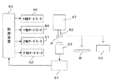
電子部品実装装置10は、図4に示す制御装置60によって制御される。制御装置60は、CPU,ROM,RAMおよび入出力インターフェースを有している。制御装置60には、入出力インターフェースを介して、部品実装ヘッド47をY軸およびX軸方向に移動するY軸およびX軸サーボモータ44、46、および吸着ノズル50をZ軸方向に移動するZ軸サーボモータ51、ならびに吸着ノズル50をZ軸線の回りに回動するθ軸サーボモータ52がそれぞれ接続されている。また、制御装置60には、部品カメラ53によって撮像された画像データを画像処理する画像処理装置61が接続されている。なお、図4中、63は吸着ノズル50で吸着されたダミー部品を回収する回収部としての回収ボックスを示し、回収ボックス63は電子部品実装装置10の所定位置、例えば、部品供給装置20の近傍に設置されている。
The electronic
次に、バルクフィーダ21Aの部品収容カセット25内にダミー部品を補給するフローチャートを図5に基づいて説明する。バルクフィーダ21Aの部品収容カセット25内には、所定個数の正規部品Pが収容されている。部品収容カセット25内に収容された正規部品Pは、部品供給路26を整列搬送されて部品取出位置P1に供給される。部品取出位置P1に供給された正規部品Pは、ステップ100において、部品実装ヘッド47に設けた吸着ノズル50により吸着されて回路基板Bに向けて搬送され、その搬送途中で正規部品Pは、部品カメラ53により吸着ノズル50の中心に対する芯ずれおよびZ軸線回りの角度ずれが検出される。しかる後、吸着ノズル50で吸着された正規部品Pは、吸着ノズル50の中心に対する芯ずれおよびZ軸線回りの角度ずれが補正された状態で、回路基板B上の定められた座標位置に実装される。
Next, a flow chart for supplying dummy parts into the
バルクフィーダ21Aより正規部品Pが取り出される毎に、ステップ102において正規部品Pの残数が管理される。すなわち、バルクフィーダ21Aより正規部品Pが取り出される毎に、制御装置60のRAMに記憶されている正規部品Pの残数が減算される。ステップ104においては、正規部品Pの残数が残り少ないN1以下になったか否かが判別され、正規部品Pの残数がN1以下の場合(判別結果がYESの場合)には、次のステップ106に移行して、ダミー部品の補給案内が指令され、ランプあるいはブザー等によって作業者に報知される。なお、正規部品Pの残数がN1より多い場合(判別結果がNOの場合)には、プログラムはリターンされる。
Each time the regular part P is taken out from the
かかるダミー部品補給案内に基づいて作業者は、ダミー部品を収容したダミー用カセット29より部品収容カセット25内に、正規部品Pとは色彩等の異なるダミー部品を所定個数補給する。これにより、バルクフィーダ21Aの部品収容カセット25内における部品(正規部品Pおよびダミー部品)の収容数が増加され、部品収容カセット25内の部品が停滞することなく、部品供給路26に円滑に供給できるようになる。この場合、ダミー部品補給後は、部品供給路26に正規部品Pとダミー部品が混在した状態で搬送されることとなる。この際、供給するダミー部品の比重が正規部品Pに比べ軽い場合、正規部品Pが先行して搬送され、ダミー部品は部品収容カセット25内に滞留する場合が多い。
Based on the dummy component supply guide, the worker supplies a predetermined number of dummy components having colors and the like different from those of the regular component P into the
次に、部品実装ヘッド47の吸着ノズル50により吸着された部品が正規部品Pかダミー部品かを判別するフローチャートを図6に基づいて説明する。バルクフィーダ21Aの部品収容カセット25内に収容された正規部品Pおよびダミー部品は、上記したと同様に、部品供給路26を搬送されて部品取出位置P1に供給され、ステップ200において、部品実装ヘッド47の吸着ノズル50により吸着される。吸着ノズル50に吸着された部品は、回路基板Bに搬送される途中で、部品カメラ53により撮像され(ステップ202)、濃淡画像が取得される。次いで、ステップ204において、画像処理装置61による画像処理によって濃淡画像が二値化され、続くステップ206において、二値化データがしきい値と比較され、吸着ノズル50で吸着された部品が正規部品Pかダミー部品かが判別される。
Next, a flowchart for determining whether a component sucked by the
ステップ206において正規部品Pであると判別された場合には、ステップ208に移行され、吸着ノズル50で吸着した正規部品Pを回路基板Bに実装する部品実装作業が実行される。これに対し、ステップ206においてダミー部品であると判別された場合には、ステップ210に移行され、吸着ノズル50で吸着したダミー部品を回収ボックス63(図4参照)に回収する回収処理が実行される。
If it is determined in
上記したステップ106によって、請求項における案内手段が構成され、ステップ204、206によって、請求項における判別手段が構成され、ステップ208によって、請求項における実装制御手段が構成されている。
The above-described
上記した実施の形態によれば、バルクフィーダ21Aの部品収容カセット25内にダミー部品を要求する案内を出す案内手段(ステップ106)と、吸着ノズル50で吸着された部品が正規部品Pであるかダミー部品であるかを判別する判別手段(ステップ204、206)と、判別手段によって、正規部品Pと判別された場合にのみ、当該部品Pを回路基板Bに実装する実装制御手段(ステップ208)とを有するので、たとえ、部品収容カセット25内の正規部品Pの数が少なくなっても、ダミー部品の補給によって、部品収容カセット25内の部品を部品供給路26に円滑に送ることができるようになり、正規部品Pを最後まで使い切ることが可能となる。ここでの案内手段とは、部品実装装置の操作画面への表示や、シグナルタワー等やバルクフィーダ21A自身が有するランプ等の点滅、または該当するバルクフィーダ21Aを取付けたデバイス台22のLEDランプの点滅等によって告知されるものである態様も含む。さらに、案内手段は、各々のフィーダ自身が有する制御装置や、フィーダを統括制御している制御装置60から発せられるものである態様も含む。従って、例えば、これらの信号に基づき、ダミー用カセット29が自動で開放され、部品収容カセット25に自動的にダミー部品が供給される態様も可能となる。
According to the above-described embodiment, the guide means (step 106) for issuing a guide requesting a dummy component in the
しかも、仮にダミー部品が部品供給路26に搬送されて、吸着ノズル50に吸着されても、判別手段(ステップ204、206)によって正規部品Pかダミー部品かを判別され、正規部品Pと判別された場合にのみ、回路基板Bに実装されるので、誤ってダミー部品が回路基板Bに実装される事態を確実に防止することができる。
Moreover, even if the dummy part is transported to the
また、吸着ノズル50に吸着された部品がダミー部品と判別された場合には、ダミー部品を回収ボックス63に回収するようにしたので、回収されたダミー部品を再利用することが可能となる。
Further, when the part sucked by the
上記した実施の形態においては、バルクフィーダ21Aの部品収容カセット25内に収容された部品(正規部品およびダミー部品)を、振動作用と加圧エアの作用によって部品供給路26に送るようにしたが、振動とエアの少なくとも一方によって部品を送ることも可能であり、あるいはまた、磁力等を利用した他の搬送手段によって部品を搬送することもできる。
In the above-described embodiment, the parts (regular parts and dummy parts) housed in the
また、上記した実施の形態においては、バルクフィーダ21Aに取付けた部品収容カセット25に、ダミー用カセット29を着脱可能に取付け、ダミー用カセット29に収容されたダミー部品を部品収容カセット25に補給するようにしたが、ダミー用カセット29を設けることなく、ダミー部品を直接部品収容カセット25に補給するようにしてもよい。
In the above-described embodiment, the
以上、本発明の実施の形態について説明したが、本発明は上記した実施の形態に限定されるものではなく、特許請求の範囲に記載した本発明の主旨を逸脱しない範囲内で種々の変形が可能であることは勿論である。 Although the embodiments of the present invention have been described above, the present invention is not limited to the above-described embodiments, and various modifications can be made without departing from the spirit of the present invention described in the claims. Of course, it is possible.
本発明に係る電子部品実装装置は、カセット内に収容された電子部品を部品供給路に整列して供給するバルクフィーダを備えたものに用いるのに適している。 The electronic component mounting apparatus according to the present invention is suitable for use in an apparatus equipped with a bulk feeder that supplies electronic components accommodated in a cassette in alignment with a component supply path.
10…電子部品実装装置、20…部品供給装置、21A…バルクフィーダ、25…部品収容カセット、26…部品供給路、27…加振装置、28…エア供給装置、29…ダミー用カセット、47…部品実装ヘッド、50…吸着ノズル、53…部品カメラ、60…制御装置、61…画像処理装置、63…回収部(回収ボックス)、106…案内手段、204、206…判別手段、208…実装制御手段。
DESCRIPTION OF
Claims (5)
前記バルクフィーダの前記カセット内にダミー部品を要求する案内を出す案内手段と、
前記吸着ノズルによって前記部品取出位置より吸着された部品が正規の電子部品であるかダミー部品であるかを判別する判別手段と、
該判別手段によって、正規の電子部品と判別された場合にのみ、当該電子部品を基板に実装する実装制御手段と、
を有することを特徴とする電子部品実装装置。 A bulk feeder for aligning electronic components and dummy components housed in a cassette with a component supply path and supplying them to a component take-out position is provided, and the electronic component supplied to the component supply path by the bulk feeder is used as a component mounting head. In an electronic component mounting apparatus that is sucked by a suction nozzle provided and mounted on a substrate,
Guidance means for providing guidance requesting dummy parts in the cassette of the bulk feeder;
A discriminating means for discriminating whether a component sucked from the component pick-up position by the suction nozzle is a regular electronic component or a dummy component;
Mounting control means for mounting the electronic component on the substrate only when the determination means determines that the electronic component is a legitimate electronic component;
An electronic component mounting apparatus comprising:
Priority Applications (2)
| Application Number | Priority Date | Filing Date | Title |
|---|---|---|---|
| JP2011133816A JP5808160B2 (en) | 2011-06-16 | 2011-06-16 | Electronic component mounting equipment |
| CN 201220293456 CN202773245U (en) | 2011-06-16 | 2012-06-18 | Electronic component installation device |
Applications Claiming Priority (1)
| Application Number | Priority Date | Filing Date | Title |
|---|---|---|---|
| JP2011133816A JP5808160B2 (en) | 2011-06-16 | 2011-06-16 | Electronic component mounting equipment |
Publications (2)
| Publication Number | Publication Date |
|---|---|
| JP2013004703A JP2013004703A (en) | 2013-01-07 |
| JP5808160B2 true JP5808160B2 (en) | 2015-11-10 |
Family
ID=47672962
Family Applications (1)
| Application Number | Title | Priority Date | Filing Date |
|---|---|---|---|
| JP2011133816A Active JP5808160B2 (en) | 2011-06-16 | 2011-06-16 | Electronic component mounting equipment |
Country Status (2)
| Country | Link |
|---|---|
| JP (1) | JP5808160B2 (en) |
| CN (1) | CN202773245U (en) |
Families Citing this family (5)
| Publication number | Priority date | Publication date | Assignee | Title |
|---|---|---|---|---|
| CN103338627B (en) * | 2013-07-18 | 2015-09-30 | 苏州盟川自动化科技有限公司 | A kind of automatism card machine produced for electronic product abnormity electronic component plug-in mounting |
| JP2016152392A (en) * | 2015-02-19 | 2016-08-22 | 株式会社村田製作所 | Printed circuit board, method of manufacturing the same and inductor product |
| EP3349558B1 (en) * | 2015-09-09 | 2020-10-21 | FUJI Corporation | Addition-type reel holding device |
| WO2019229880A1 (en) | 2018-05-30 | 2019-12-05 | ヤマハ発動機株式会社 | Component replenishment management system and component mounting system |
| WO2020039542A1 (en) * | 2018-08-23 | 2020-02-27 | 株式会社Fuji | Moving work management device, mounting system, moving work device, and moving work management method |
Family Cites Families (6)
| Publication number | Priority date | Publication date | Assignee | Title |
|---|---|---|---|---|
| JPH02169407A (en) * | 1988-12-21 | 1990-06-29 | Aichi Steel Works Ltd | Method for conveying article |
| JPH04296099A (en) * | 1991-03-26 | 1992-10-20 | Matsushita Electric Ind Co Ltd | Electronic part mounting equipment with recognizing function |
| JP3552733B2 (en) * | 1993-06-22 | 2004-08-11 | 株式会社日立ハイテクインスツルメンツ | Electronic component mounting system |
| JPH09130092A (en) * | 1995-10-31 | 1997-05-16 | Mitsumi Electric Co Ltd | Chip mounter |
| JP3642186B2 (en) * | 1998-06-01 | 2005-04-27 | 松下電器産業株式会社 | Method for teaching the nozzle height of a multi-nozzle head in an electronic component mounting apparatus |
| JP2000332500A (en) * | 1999-05-17 | 2000-11-30 | Matsushita Electric Ind Co Ltd | Method for setting illumination of electronic component |
-
2011
- 2011-06-16 JP JP2011133816A patent/JP5808160B2/en active Active
-
2012
- 2012-06-18 CN CN 201220293456 patent/CN202773245U/en not_active Expired - Fee Related
Also Published As
| Publication number | Publication date |
|---|---|
| JP2013004703A (en) | 2013-01-07 |
| CN202773245U (en) | 2013-03-06 |
Similar Documents
| Publication | Publication Date | Title |
|---|---|---|
| US10420262B2 (en) | Feeder management device | |
| WO2014049766A1 (en) | Recognition device for substrate processing machine | |
| JP5808160B2 (en) | Electronic component mounting equipment | |
| JP6348687B2 (en) | Nozzle container | |
| JP2011199217A (en) | Feeder management method and component mounting apparatus | |
| JP5075214B2 (en) | Electronic component mounting device | |
| JP5214478B2 (en) | Electronic component mounting method and electronic component mounting apparatus | |
| US10015920B2 (en) | Component mounting method in component mounting system | |
| KR20120112068A (en) | Component mounting device, information processing device, information processing method, and substrate manufacturing method | |
| JP2018190944A (en) | Component mounting system | |
| JP4995745B2 (en) | Component mounting equipment | |
| JP6412125B2 (en) | Parts mounting machine | |
| JP5342230B2 (en) | Electronic component mounting apparatus and electronic component mounting method | |
| JP2022161896A (en) | Component management device and component management method | |
| US20130297056A1 (en) | Production system and data generation method | |
| JP6095668B2 (en) | Electronic component mounting machine | |
| JP2010050380A (en) | Component mounting apparatus and component mounting method | |
| JP7590552B2 (en) | Judgment device | |
| JPWO2018105073A1 (en) | Service system and server | |
| US20210153399A1 (en) | Information processing device, work system, and determination method | |
| WO2023012981A1 (en) | Component mounting system | |
| WO2018211657A1 (en) | Component feeding device | |
| JP6318367B2 (en) | Component mounting method and component mounting apparatus | |
| JP4664995B2 (en) | Component mounting equipment | |
| WO2023007740A1 (en) | Component mounting system and component mounting method |
Legal Events
| Date | Code | Title | Description |
|---|---|---|---|
| A621 | Written request for application examination |
Free format text: JAPANESE INTERMEDIATE CODE: A621 Effective date: 20140604 |
|
| A977 | Report on retrieval |
Free format text: JAPANESE INTERMEDIATE CODE: A971007 Effective date: 20150218 |
|
| A131 | Notification of reasons for refusal |
Free format text: JAPANESE INTERMEDIATE CODE: A131 Effective date: 20150224 |
|
| A521 | Request for written amendment filed |
Free format text: JAPANESE INTERMEDIATE CODE: A523 Effective date: 20150416 |
|
| TRDD | Decision of grant or rejection written | ||
| A01 | Written decision to grant a patent or to grant a registration (utility model) |
Free format text: JAPANESE INTERMEDIATE CODE: A01 Effective date: 20150818 |
|
| A61 | First payment of annual fees (during grant procedure) |
Free format text: JAPANESE INTERMEDIATE CODE: A61 Effective date: 20150908 |
|
| R150 | Certificate of patent or registration of utility model |
Ref document number: 5808160 Country of ref document: JP Free format text: JAPANESE INTERMEDIATE CODE: R150 |
|
| R250 | Receipt of annual fees |
Free format text: JAPANESE INTERMEDIATE CODE: R250 |
|
| S533 | Written request for registration of change of name |
Free format text: JAPANESE INTERMEDIATE CODE: R313533 |
|
| R350 | Written notification of registration of transfer |
Free format text: JAPANESE INTERMEDIATE CODE: R350 |
|
| R250 | Receipt of annual fees |
Free format text: JAPANESE INTERMEDIATE CODE: R250 |
|
| R250 | Receipt of annual fees |
Free format text: JAPANESE INTERMEDIATE CODE: R250 |
|
| R250 | Receipt of annual fees |
Free format text: JAPANESE INTERMEDIATE CODE: R250 |
|
| R250 | Receipt of annual fees |
Free format text: JAPANESE INTERMEDIATE CODE: R250 |
|
| R250 | Receipt of annual fees |
Free format text: JAPANESE INTERMEDIATE CODE: R250 |
|
| R250 | Receipt of annual fees |
Free format text: JAPANESE INTERMEDIATE CODE: R250 |