JP5783918B2 - connector - Google Patents
connector Download PDFInfo
- Publication number
- JP5783918B2 JP5783918B2 JP2012008521A JP2012008521A JP5783918B2 JP 5783918 B2 JP5783918 B2 JP 5783918B2 JP 2012008521 A JP2012008521 A JP 2012008521A JP 2012008521 A JP2012008521 A JP 2012008521A JP 5783918 B2 JP5783918 B2 JP 5783918B2
- Authority
- JP
- Japan
- Prior art keywords
- terminal
- short
- connector
- contact piece
- housing body
- Prior art date
- Legal status (The legal status is an assumption and is not a legal conclusion. Google has not performed a legal analysis and makes no representation as to the accuracy of the status listed.)
- Active
Links
- 238000003780 insertion Methods 0.000 claims description 6
- 230000037431 insertion Effects 0.000 claims description 6
- 230000000149 penetrating effect Effects 0.000 claims description 5
- 239000002184 metal Substances 0.000 claims description 4
- 210000000078 claw Anatomy 0.000 description 2
- 230000005489 elastic deformation Effects 0.000 description 2
- 238000005452 bending Methods 0.000 description 1
- 230000000694 effects Effects 0.000 description 1
- 239000000463 material Substances 0.000 description 1
- 239000007769 metal material Substances 0.000 description 1
- 238000000034 method Methods 0.000 description 1
- 238000012986 modification Methods 0.000 description 1
- 230000004048 modification Effects 0.000 description 1
- 239000011347 resin Substances 0.000 description 1
- 229920005989 resin Polymers 0.000 description 1
Images


Classifications
-
- H—ELECTRICITY
- H01—ELECTRIC ELEMENTS
- H01R—ELECTRICALLY-CONDUCTIVE CONNECTIONS; STRUCTURAL ASSOCIATIONS OF A PLURALITY OF MUTUALLY-INSULATED ELECTRICAL CONNECTING ELEMENTS; COUPLING DEVICES; CURRENT COLLECTORS
- H01R4/00—Electrically-conductive connections between two or more conductive members in direct contact, i.e. touching one another; Means for effecting or maintaining such contact; Electrically-conductive connections having two or more spaced connecting locations for conductors and using contact members penetrating insulation
- H01R4/58—Electrically-conductive connections between two or more conductive members in direct contact, i.e. touching one another; Means for effecting or maintaining such contact; Electrically-conductive connections having two or more spaced connecting locations for conductors and using contact members penetrating insulation characterised by the form or material of the contacting members
- H01R4/66—Connections with the terrestrial mass, e.g. earth plate, earth pin
-
- H—ELECTRICITY
- H01—ELECTRIC ELEMENTS
- H01R—ELECTRICALLY-CONDUCTIVE CONNECTIONS; STRUCTURAL ASSOCIATIONS OF A PLURALITY OF MUTUALLY-INSULATED ELECTRICAL CONNECTING ELEMENTS; COUPLING DEVICES; CURRENT COLLECTORS
- H01R31/00—Coupling parts supported only by co-operation with counterpart
- H01R31/08—Short-circuiting members for bridging contacts in a counterpart
-
- H—ELECTRICITY
- H01—ELECTRIC ELEMENTS
- H01R—ELECTRICALLY-CONDUCTIVE CONNECTIONS; STRUCTURAL ASSOCIATIONS OF A PLURALITY OF MUTUALLY-INSULATED ELECTRICAL CONNECTING ELEMENTS; COUPLING DEVICES; CURRENT COLLECTORS
- H01R13/00—Details of coupling devices of the kinds covered by groups H01R12/70 or H01R24/00 - H01R33/00
- H01R13/40—Securing contact members in or to a base or case; Insulating of contact members
- H01R13/405—Securing in non-demountable manner, e.g. moulding, riveting
- H01R13/41—Securing in non-demountable manner, e.g. moulding, riveting by frictional grip in grommet, panel or base
-
- H—ELECTRICITY
- H01—ELECTRIC ELEMENTS
- H01R—ELECTRICALLY-CONDUCTIVE CONNECTIONS; STRUCTURAL ASSOCIATIONS OF A PLURALITY OF MUTUALLY-INSULATED ELECTRICAL CONNECTING ELEMENTS; COUPLING DEVICES; CURRENT COLLECTORS
- H01R13/00—Details of coupling devices of the kinds covered by groups H01R12/70 or H01R24/00 - H01R33/00
- H01R13/40—Securing contact members in or to a base or case; Insulating of contact members
- H01R13/42—Securing in a demountable manner
- H01R13/436—Securing a plurality of contact members by one locking piece or operation
- H01R13/4361—Insertion of locking piece perpendicular to direction of contact insertion
- H01R13/4362—Insertion of locking piece perpendicular to direction of contact insertion comprising a temporary and a final locking position
-
- H—ELECTRICITY
- H01—ELECTRIC ELEMENTS
- H01R—ELECTRICALLY-CONDUCTIVE CONNECTIONS; STRUCTURAL ASSOCIATIONS OF A PLURALITY OF MUTUALLY-INSULATED ELECTRICAL CONNECTING ELEMENTS; COUPLING DEVICES; CURRENT COLLECTORS
- H01R13/00—Details of coupling devices of the kinds covered by groups H01R12/70 or H01R24/00 - H01R33/00
- H01R13/62—Means for facilitating engagement or disengagement of coupling parts or for holding them in engagement
- H01R13/639—Additional means for holding or locking coupling parts together, after engagement, e.g. separate keylock, retainer strap
-
- H—ELECTRICITY
- H01—ELECTRIC ELEMENTS
- H01R—ELECTRICALLY-CONDUCTIVE CONNECTIONS; STRUCTURAL ASSOCIATIONS OF A PLURALITY OF MUTUALLY-INSULATED ELECTRICAL CONNECTING ELEMENTS; COUPLING DEVICES; CURRENT COLLECTORS
- H01R13/00—Details of coupling devices of the kinds covered by groups H01R12/70 or H01R24/00 - H01R33/00
- H01R13/64—Means for preventing incorrect coupling
Landscapes
- Connector Housings Or Holding Contact Members (AREA)
Description
本発明は、コネクタに関し、特には2つの端子を短絡させる技術に関する。 The present invention relates to a connector, and more particularly to a technique for short-circuiting two terminals.
特許文献1には、2つの端子を短絡させるための短絡部材を備えるコネクタが開示されている。この短絡部材は、U字状に折り曲げられた金属板からなり、筐体に固定される本体部と、本体部と対向する板厚方向に弾性変形可能な一対の接触片と、を有している。
しかしながら、上記従来技術では、接触片を十分な力で端子と接触させるために本体部と接触片との間に比較的大きな隙間が必要であることから、コネクタの小型化が困難である。 However, in the above prior art, since a relatively large gap is required between the main body portion and the contact piece in order to bring the contact piece into contact with the terminal with sufficient force, it is difficult to reduce the size of the connector.
本発明は、上記実情に鑑みて為されたものであり、2つの端子を短絡させる短絡部材を備えつつも小型化を図ることが可能なコネクタを提供することを主な目的とする。 The present invention has been made in view of the above circumstances, and a main object of the present invention is to provide a connector that can be miniaturized while including a short-circuit member that short-circuits two terminals.
上記課題を解決するため、本発明のコネクタは、一方向に貫通し、片方の側から端子が挿入される複数の端子穴が形成された筐体本体と、前記筐体本体の前記一方向の他方の側に取り付けられ、前記複数の端子穴に対応する複数の端子穴が形成されたカバー部材と、前記筐体本体と前記カバー部材との間に配置される短絡部材と、を備える。前記短絡部材は、前記筐体本体の第1の端子穴に挿入される端子と接触することで弾性変形する第1の接触片と、第2の端子穴に挿入される端子と接触することで弾性変形する第2の接触片と、を有する。前記短絡部材は金属板からなり、前記第1の接触片と前記第2の接触片は、面内の互いに近付く方向に弾性変形する。 In order to solve the above-described problems, a connector according to the present invention includes a housing main body formed with a plurality of terminal holes penetrating in one direction and into which terminals are inserted from one side, and the one-way of the housing main body. A cover member attached to the other side and formed with a plurality of terminal holes corresponding to the plurality of terminal holes, and a short-circuit member disposed between the housing body and the cover member. The short-circuit member is in contact with a first contact piece that is elastically deformed by contact with a terminal inserted into the first terminal hole of the housing body, and a terminal inserted into the second terminal hole. A second contact piece that is elastically deformed. The short-circuit member is made of a metal plate, and the first contact piece and the second contact piece are elastically deformed in a direction approaching each other in a plane.
本発明によると、2つの接触片が面内の互いに近づく方向に弾性変形するため、2つの接触片が板厚方向に弾性変形する場合と比較して、小さな弾性変形量で大きな弾性復帰力を得ることが可能である。このため、短絡部材を備えるコネクタの小型化を図ることが可能である。 According to the present invention, since the two contact pieces are elastically deformed in the direction in which the two contact pieces approach each other, a large elastic return force can be obtained with a small elastic deformation amount as compared with the case where the two contact pieces elastically deform in the plate thickness direction. It is possible to obtain. For this reason, it is possible to reduce the size of the connector including the short-circuit member.
また、本発明の一態様によると、前記短絡部材は、前記第1の接触片と前記第2の接触片との間で前記カバー部材と係合する中間片を有する。これによると、一方の接触片の弾性変形の影響が他方の接触片に及ぶことを抑制することが可能である。 According to an aspect of the present invention, the short-circuit member includes an intermediate piece that engages with the cover member between the first contact piece and the second contact piece. According to this, it is possible to suppress the influence of the elastic deformation of one contact piece from reaching the other contact piece.
また、本発明の一態様によると、前記短絡部材は、前記端子の挿入方向と同じ方向に前記カバー部材に嵌め込まれる固定部を有する。これによると、接触片に端子が接触するときに短絡部材がずれることを抑制することが可能である。 Moreover, according to one aspect of the present invention, the short-circuit member has a fixing portion that is fitted into the cover member in the same direction as the insertion direction of the terminal. According to this, it is possible to suppress the short-circuit member from shifting when the terminal contacts the contact piece.
本発明のコネクタの実施形態を、図面を参照しながら説明する。 An embodiment of a connector of the present invention will be described with reference to the drawings.
図1A及び図1Bは、コネクタ1の斜視図である。図2A及び図2Bは、コネクタ1に含まれる第1のコネクタ2の斜視図である。図3は、第1のコネクタ2に含まれるカバー部材5と短絡部材7の斜視図である。図4は、第1のコネクタ2に含まれる筐体本体4の側面図である。図5は、第1のコネクタ2の断面図である。図6A〜図6Cは、短絡部材の平面図、側面図及び下面図である。図7は、第1のコネクタ2の断面図である。これらの図では、第2のコネクタ3に対する第1のコネクタ2の挿入方向を前方向とし、第1のコネクタ2の筐体本体4のうち、係合片49が設けられた方向を上方向とする。
1A and 1B are perspective views of the
図1A及び図1Bに示されるように、コネクタ1は、複数のケーブル92が接続された概略円柱状の第1のコネクタ2と、複数のケーブル94が接続された概略円筒状の第2のコネクタ3と、を備えている。第2のコネクタ3は、第1のコネクタ2が挿入される後方に向けて開放された挿入穴3aを有している。第2のコネクタ3の側壁の上部には、第1のコネクタ2の係合片49と係合する係合穴3bが形成されている。また、第2のコネクタ3の内側面の下部には、前後方向に延びるレール部31が設けられている。
As shown in FIGS. 1A and 1B, the
図2A〜図3に示されるように、第1のコネクタ2は、概略円柱状の筐体本体4と、筐体本体4の前部に取り付けられるカバー部材5と、端子91(図5を参照)の抜け止めのための保持部材6と、2つの端子91を短絡させるための短絡部材7と、を備えている。筐体本体4、カバー部材5及び保持部材6は、絶縁性の樹脂材料で成型されている。短絡部材7は、導電性の金属材料からなる。
As shown in FIGS. 2A to 3, the
筐体本体4には、軸心方向である前後方向に貫通する複数の端子穴4aが形成されている。これら端子穴4aには、後方から端子91(図5を参照)が挿入される。また、筐体本体4には、側面の下部に開口を有し、開口から上方に延びる保持穴4cが形成されている。この保持穴4cは、複数の端子穴4aと連通している。保持穴4cは、筐体本体4の前後方向の中央部に形成されており、左右方向に広がった形状を有している。
The
筐体本体4の上部の左右両側には、前端から後方に延びる溝42aが形成されている。これらの溝42aの内側には、外側方に突出する係合片42が設けられている。また、各々の端子穴4aの下方には、前方に向かうに従って上方に張り出した係合片47が設けられている(図4及び図5を参照)。
カバー部材5は、前後方向に貫通する複数の端子穴5aが形成された概略円板状の円板部51と、円板部51の縁の上部の左右両側から後方に延びる2つの係合片52と、円板部51の縁の下部から後方に延びる顎部54と、を備えている。複数の端子穴5aは、筐体本体4に形成された複数の端子穴4aに対応している。具体的には、各々の端子穴5aは、カバー部材5が筐体本体4に取り付けられたときに、筐体本体4に形成された各々の端子穴4aと前後方向に連続するように配置されている。
The
各々の係合片52には、前後方向に延びて、後端が閉じられた溝52aが形成されている。これら係合片52は、筐体本体4に設けられた係合片42と係合する。具体的には、カバー部材5の係合片52が筐体本体4の溝42aに挿入され、係合片52に形成された溝52aに、溝42aに設けられた係合片42が挿入される。
Each
顎部54の先端部には、内側方に突出する係合片56が設けられている。この係合片56は、筐体本体4に形成された保持穴4cに係合する(詳細は後述する)。また、顎部54には、前端から後方に延びるスリット5bが形成されている。このスリット5bには、上記第2のコネクタ3の内側面に設けられたレール部31が挿入される。
An engaging
円板部51の縁に設けられる合計3つの係合片52,56は、円板部51の中心を基準におおよそ120度の角度ごとに配置されている。このため、カバー部材5を筐体本体4に安定的に固定することが可能である。
A total of three
さらに、カバー部材5は、円板部51の後面の中央付近から後方に延びた、短絡部材7を支持するための支持部58を備えている(図3を参照)。支持部58には、短絡部材7を固定するための圧入穴58aが形成されている。
Further, the
保持部材6は、概略板状に成形されており、筐体本体4に形成された保持穴4cに下方から上方に向けて挿入される。保持部材6は、その上面や、前後方向に貫通する端子穴6aの下面に、複数の係合部61を有している。各々の係合部61は、筐体本体4に形成された複数の端子穴4aに対応している。保持部材6の下端部には、後方に張り出した被押圧部63が設けられている。被押圧部63の後面には、後方に突出した係合片65が設けられている。また、保持部材6の下端部の前側には、凹部6cが形成されている。
The holding
図5に示されるように、保持部材6が筐体本体4の保持穴4cに挿入されるとき、保持部材6の各々の係合部61は、筐体本体4に形成された各々の端子穴4aの下面よりも上方に張り出して、各々の端子穴4aに挿入された端子91の基端部に形成された凹部に係合する。これにより、端子穴4aからの端子91の抜けが抑制される。また、筐体本体4の前端部に設けられた係合片47は、各々の端子穴4aに挿入された端子91の先端部に係合する。これによっても、端子穴4aからの端子91の抜けが抑制される。
As shown in FIG. 5, when the holding
カバー部材5の顎部54に設けられた係合片56は、保持部材6が挿入された保持穴4cの開口の前側の縁部43に掛けられる。すなわち、係合片56は、保持穴4cの開口付近に挿入され、前側の縁部43の後面と接触ないし対向する。このとき、係合片56は、保持部材6の下端部に形成された凹部6cに挿入される。
The engaging
カバー部材5は、下部に設けられた係合片56が保持穴4cの開口の縁部43に掛けられた後、上部に設けられた2つの係合片52が筐体本体4の側面の2つの係合片42と係合することで(または、その逆の順序であってもよい。)、筐体本体4の前部に取り付けられる。
In the
保持部材6の被押圧部63は、カバー部材5の顎部54から離れるように後方に延びており、保持穴4cの開口の後方に形成された凹部43a(図4を参照)に挿入される。被押圧部63の後面に設けられた係合片65は、凹部43aの後方の凸部45に形成された係合穴45aに係合する。
The pressed
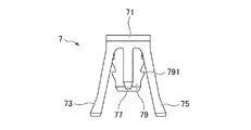
図6A〜図6Cに示される短絡部材7は、打ち抜かれた金属板が折り曲げられることによって成形される。短絡部材7は、U字状に折り曲げられた基端部71と、基端部71の上部から後方に向けて延びる第1の接触片73、第2の接触片75、中間片77と、基端部71の下部から後方に向けて延びる固定部79と、を備えている。
The short-
第1の接触片73と第2の接触片75は、基端部71から後方に向かうに従って面内の左右外方に互いに離れており、面内の左右内方に向かって互いに近付くように弾性変形可能である。中間片77は、基端部71から第1の接触片73と第2の接触片75の間に延びている。固定部79は、左右両側に抜け止めのための爪部791を有している。
The
図7に示されるように、短絡部材7は、筐体本体4とカバー部材5との間に配置されている。短絡部材7は、固定部79がカバー部材5の支持部58の圧入穴58aに圧入されることで、カバー部材5に固定される(図3を参照)。短絡部材7がカバー部材5に固定されるとき、短絡部材7の中間片77は、カバー部材5の支持部58に設けられた係合部581に係合する。
As shown in FIG. 7, the short-
短絡部材7の第1の接触片73と第2の接触片75は、カバー部材5の支持部58の左右各側に位置する端子穴4aの内側に張り出している。すなわち、第1の接触片73と第2の接触片75は、端子穴4aに挿入される端子91の経路上に張り出している。また、第1の接触片73と第2の接触片75は、前方に向かうに従って端子91の経路上に張り出す量が増大している。なお、第1の接触片73と第2の接触片75は、カバー部材5に形成された端子穴5aのみに張り出してもよいし、端子穴4aと端子穴5aの両方に張り出してもよい。
The
第1の接触片73と第2の接触片75は、端子穴4aに挿入される端子91と接触することで、中間片77に向けて弾性変形し、端子91に対する接触力を生じる。このとき、中間片77がカバー部材5の係合部581に係合しているため、第1の接触片73と第2の接触片75の一方が端子91と接触して弾性変形しても、その影響が他方まで及びにくい。また、短絡部材7の固定部79は、端子91の挿入方向と同じ方向にカバー部材5に嵌め込まれるため(図3を参照)、第1の接触片73と第2の接触片75が端子91と接触しても、短絡部材7がずれにくい。
The
以上、本発明の実施形態について説明したが、本発明は上記実施形態に限定されるものではなく、種々の変形実施が当業者にとって可能であるのはもちろんである。 Although the embodiments of the present invention have been described above, the present invention is not limited to the above-described embodiments, and various modifications can be made by those skilled in the art.
1 コネクタ、2 第1のコネクタ、3 第2のコネクタ、3a 挿入穴、3b 係合穴、31 レール部、4 筐体本体、4a 端子穴、4c 保持穴、42 係合片、42a 溝、43 縁部、43c 凹部、45 凸部、45a 係合穴、47 係合片、49 係合片、5 カバー部材、5a 端子穴、5c スリット、51 円板部、52 係合片、52a 溝、54 顎部、56 係合片、58 支持部、58a 圧入穴、581 係合部、6 保持部材、6a 端子穴、6c 凹部、61 係合部、63 被押圧部、65 係合片、7 短絡部材、71 基端部、73 第1の接触片、75 第2の接触片、77 中間片、79 固定部、791 爪部、91 端子、92 ケーブル、94 ケーブル。 1 connector, 2 first connector, 3 second connector, 3a insertion hole, 3b engagement hole, 31 rail part, 4 housing body, 4a terminal hole, 4c holding hole, 42 engagement piece, 42a groove, 43 Edge, 43c Concave, 45 Convex, 45a Engagement hole, 47 Engagement piece, 49 Engagement piece, 5 Cover member, 5a Terminal hole, 5c Slit, 51 Disc part, 52 Engagement piece, 52a Groove, 54 Jaw portion, 56 engaging piece, 58 supporting portion, 58a press-fitting hole, 581 engaging portion, 6 holding member, 6a terminal hole, 6c recess, 61 engaging portion, 63 pressed portion, 65 engaging piece, 7 short-circuit member , 71 Base end part, 73 1st contact piece, 75 2nd contact piece, 77 Intermediate piece, 79 Fixing part, 791 Claw part, 91 terminal, 92 cable, 94 cable.
Claims (3)
前記筐体本体の前記一方向の他方の側に取り付けられ、前記複数の端子穴に対応する複数の端子穴が形成されたカバー部材と、
前記筐体本体と前記カバー部材との間に配置される短絡部材であって、前記筐体本体の第1の端子穴に挿入される端子と接触することで弾性変形する第1の接触片と、第2の端子穴に挿入される端子と接触することで弾性変形する第2の接触片と、を有する短絡部材と、
を備え、
前記短絡部材は、金属板からなり、
前記第1の接触片と前記第2の接触片は、面内の互いに近付く方向に弾性変形する、
ことを特徴とするコネクタ。 A housing body formed with a plurality of terminal holes penetrating in one direction and inserting terminals from one side;
A cover member attached to the other side of the one direction of the housing body and formed with a plurality of terminal holes corresponding to the plurality of terminal holes;
A short-circuit member disposed between the housing body and the cover member; and a first contact piece that is elastically deformed by contact with a terminal inserted into the first terminal hole of the housing body; A second contact piece that elastically deforms by contact with a terminal inserted into the second terminal hole, and a short-circuit member,
With
The short-circuit member is made of a metal plate,
The first contact piece and the second contact piece are elastically deformed in a direction approaching each other in a plane,
A connector characterized by that.
請求項1に記載のコネクタ。 The short-circuit member includes an intermediate piece that engages with the cover member between the first contact piece and the second contact piece.
The connector according to claim 1.
請求項1または2に記載のコネクタ。 The short-circuit member has a fixing portion that is fitted into the cover member in the same direction as the insertion direction of the terminal.
The connector according to claim 1 or 2.
Priority Applications (5)
| Application Number | Priority Date | Filing Date | Title |
|---|---|---|---|
| JP2012008521A JP5783918B2 (en) | 2012-01-18 | 2012-01-18 | connector |
| EP13738377.4A EP2805385A4 (en) | 2012-01-18 | 2013-01-17 | Connector |
| PCT/US2013/021931 WO2013109747A1 (en) | 2012-01-18 | 2013-01-17 | Connector |
| US14/373,101 US20150017823A1 (en) | 2012-01-18 | 2013-01-17 | Connector |
| CN201380011622.8A CN104412464A (en) | 2012-01-18 | 2013-01-17 | Connector |
Applications Claiming Priority (1)
| Application Number | Priority Date | Filing Date | Title |
|---|---|---|---|
| JP2012008521A JP5783918B2 (en) | 2012-01-18 | 2012-01-18 | connector |
Publications (2)
| Publication Number | Publication Date |
|---|---|
| JP2013149450A JP2013149450A (en) | 2013-08-01 |
| JP5783918B2 true JP5783918B2 (en) | 2015-09-24 |
Family
ID=48799652
Family Applications (1)
| Application Number | Title | Priority Date | Filing Date |
|---|---|---|---|
| JP2012008521A Active JP5783918B2 (en) | 2012-01-18 | 2012-01-18 | connector |
Country Status (5)
| Country | Link |
|---|---|
| US (1) | US20150017823A1 (en) |
| EP (1) | EP2805385A4 (en) |
| JP (1) | JP5783918B2 (en) |
| CN (1) | CN104412464A (en) |
| WO (1) | WO2013109747A1 (en) |
Families Citing this family (6)
| Publication number | Priority date | Publication date | Assignee | Title |
|---|---|---|---|---|
| JP6117054B2 (en) * | 2013-08-28 | 2017-04-19 | モレックス エルエルシー | connector |
| JP2015072868A (en) * | 2013-10-04 | 2015-04-16 | モレックス インコーポレイテドMolex Incorporated | Connector |
| DE102015214284B4 (en) | 2015-07-28 | 2017-03-30 | Te Connectivity Germany Gmbh | Electrical connector with vibration resistant jumper and electrical connector |
| JP6427145B2 (en) * | 2016-07-29 | 2018-11-21 | 矢崎総業株式会社 | connector |
| US11203027B2 (en) | 2018-08-21 | 2021-12-21 | General Electric Company | Lower gas flow injection system and method for additive manufacturing system |
| JP7087986B2 (en) * | 2018-12-21 | 2022-06-21 | 住友電装株式会社 | Split connector |
Family Cites Families (14)
| Publication number | Priority date | Publication date | Assignee | Title |
|---|---|---|---|---|
| US4906203A (en) * | 1988-10-24 | 1990-03-06 | General Motors Corporation | Electrical connector with shorting clip |
| JP3085691B2 (en) * | 1990-07-03 | 2000-09-11 | 菱星電装株式会社 | Joint connector |
| US5123854A (en) * | 1991-03-13 | 1992-06-23 | Molex Incorporated | Shunted electrical connector |
| US5266043A (en) * | 1992-01-31 | 1993-11-30 | Augat Inc. | Fully programmable connector |
| US5370543A (en) * | 1992-07-24 | 1994-12-06 | Fujikura Ltd. | Electrical connector |
| JP2725752B2 (en) * | 1992-12-14 | 1998-03-11 | 矢崎総業株式会社 | connector |
| JP2725759B2 (en) * | 1993-11-18 | 1998-03-11 | 矢崎総業株式会社 | Connector coupling detection device and short-circuit contact |
| JP3391419B2 (en) * | 1994-04-20 | 2003-03-31 | 住友電装株式会社 | connector |
| US5618201A (en) * | 1994-06-14 | 1997-04-08 | Yazaki Corporation | Connector having engagement detecting device |
| JP3268384B2 (en) * | 1997-04-28 | 2002-03-25 | 日本航空電子工業株式会社 | connector |
| JP2001196142A (en) * | 2000-01-07 | 2001-07-19 | Sumitomo Wiring Syst Ltd | Connector |
| JP4682032B2 (en) * | 2005-12-07 | 2011-05-11 | 矢崎総業株式会社 | Connector and connector unit |
| JP5218074B2 (en) * | 2008-04-28 | 2013-06-26 | 住友電装株式会社 | connector |
| JP5703139B2 (en) * | 2011-06-20 | 2015-04-15 | モレックス インコーポレイテドMolex Incorporated | connector |
-
2012
- 2012-01-18 JP JP2012008521A patent/JP5783918B2/en active Active
-
2013
- 2013-01-17 EP EP13738377.4A patent/EP2805385A4/en not_active Withdrawn
- 2013-01-17 CN CN201380011622.8A patent/CN104412464A/en active Pending
- 2013-01-17 WO PCT/US2013/021931 patent/WO2013109747A1/en active Application Filing
- 2013-01-17 US US14/373,101 patent/US20150017823A1/en not_active Abandoned
Also Published As
| Publication number | Publication date |
|---|---|
| EP2805385A4 (en) | 2015-10-28 |
| CN104412464A (en) | 2015-03-11 |
| EP2805385A1 (en) | 2014-11-26 |
| JP2013149450A (en) | 2013-08-01 |
| WO2013109747A1 (en) | 2013-07-25 |
| US20150017823A1 (en) | 2015-01-15 |
Similar Documents
| Publication | Publication Date | Title |
|---|---|---|
| JP5783918B2 (en) | connector | |
| JP5422776B1 (en) | connector | |
| JP5703139B2 (en) | connector | |
| JP2007165194A (en) | Connector | |
| JP2015072868A (en) | Connector | |
| JP6231593B2 (en) | connector | |
| JP5653202B2 (en) | connector | |
| JP6085527B2 (en) | Female terminal | |
| JP2015220005A (en) | Board-to-board connector | |
| JP5835115B2 (en) | Terminal fitting | |
| JP2018022551A (en) | Female terminal and connector having the same | |
| JP2016110706A (en) | Connector assembly | |
| JPWO2018012243A1 (en) | connector | |
| JP2009129710A (en) | connector | |
| JP2013093133A (en) | Connector terminal | |
| JP4684191B2 (en) | connector | |
| JP6368267B2 (en) | Connector and electrical connection device | |
| JP5869346B2 (en) | Holder, holder with flat conductor, and assembly of holder with flat conductor and electrical connector | |
| JP5896513B2 (en) | Jack connector | |
| JP2018133334A (en) | Mounting metal fitting, connector, header and connection system | |
| JP5872970B2 (en) | Connector terminal and connection structure between this connector terminal and mating terminal | |
| JP3169822U (en) | connector | |
| JP5734003B2 (en) | Terminal | |
| JP2018063772A (en) | Contact, connector member, and connector | |
| JP5995781B2 (en) | connector |
Legal Events
| Date | Code | Title | Description |
|---|---|---|---|
| A621 | Written request for application examination |
Free format text: JAPANESE INTERMEDIATE CODE: A621 Effective date: 20141028 |
|
| A977 | Report on retrieval |
Free format text: JAPANESE INTERMEDIATE CODE: A971007 Effective date: 20150611 |
|
| TRDD | Decision of grant or rejection written | ||
| A01 | Written decision to grant a patent or to grant a registration (utility model) |
Free format text: JAPANESE INTERMEDIATE CODE: A01 Effective date: 20150707 |
|
| A61 | First payment of annual fees (during grant procedure) |
Free format text: JAPANESE INTERMEDIATE CODE: A61 Effective date: 20150721 |
|
| R150 | Certificate of patent or registration of utility model |
Ref document number: 5783918 Country of ref document: JP Free format text: JAPANESE INTERMEDIATE CODE: R150 |
|
| S533 | Written request for registration of change of name |
Free format text: JAPANESE INTERMEDIATE CODE: R313533 |
|
| R350 | Written notification of registration of transfer |
Free format text: JAPANESE INTERMEDIATE CODE: R350 |
|
| R250 | Receipt of annual fees |
Free format text: JAPANESE INTERMEDIATE CODE: R250 |
|
| R250 | Receipt of annual fees |
Free format text: JAPANESE INTERMEDIATE CODE: R250 |
|
| R250 | Receipt of annual fees |
Free format text: JAPANESE INTERMEDIATE CODE: R250 |
|
| R250 | Receipt of annual fees |
Free format text: JAPANESE INTERMEDIATE CODE: R250 |
|
| R250 | Receipt of annual fees |
Free format text: JAPANESE INTERMEDIATE CODE: R250 |
|
| S111 | Request for change of ownership or part of ownership |
Free format text: JAPANESE INTERMEDIATE CODE: R313117 |
|
| R350 | Written notification of registration of transfer |
Free format text: JAPANESE INTERMEDIATE CODE: R350 |
|
| R250 | Receipt of annual fees |
Free format text: JAPANESE INTERMEDIATE CODE: R250 |
|
| R250 | Receipt of annual fees |
Free format text: JAPANESE INTERMEDIATE CODE: R250 |