[go: up one dir, main page]

JP5686149B2 - Dust amount detection device and vacuum cleaner using the same - Google Patents

Dust amount detection device and vacuum cleaner using the same Download PDF

Info

Publication number
JP5686149B2
JP5686149B2 JP2013037097A JP2013037097A JP5686149B2 JP 5686149 B2 JP5686149 B2 JP 5686149B2 JP 2013037097 A JP2013037097 A JP 2013037097A JP 2013037097 A JP2013037097 A JP 2013037097A JP 5686149 B2 JP5686149 B2 JP 5686149B2
Authority
JP
Japan
Prior art keywords
dust
unit
amount detection
detection device
signal
Prior art date
Legal status (The legal status is an assumption and is not a legal conclusion. Google has not performed a legal analysis and makes no representation as to the accuracy of the status listed.)
Expired - Fee Related
Application number
JP2013037097A
Other languages
Japanese (ja)
Other versions
JP2014161611A (en
Inventor
亮輔 安部
亮輔 安部
大石 智子
智子 大石
安藤 宏
宏 安藤
飯塚 政義
政義 飯塚
昌美 頼田
昌美 頼田
Current Assignee (The listed assignees may be inaccurate. Google has not performed a legal analysis and makes no representation or warranty as to the accuracy of the list.)
Mitsubishi Electric Home Appliance Co Ltd
Mitsubishi Electric Corp
Original Assignee
Mitsubishi Electric Home Appliance Co Ltd
Mitsubishi Electric Corp
Priority date (The priority date is an assumption and is not a legal conclusion. Google has not performed a legal analysis and makes no representation as to the accuracy of the date listed.)
Filing date
Publication date
Application filed by Mitsubishi Electric Home Appliance Co Ltd, Mitsubishi Electric Corp filed Critical Mitsubishi Electric Home Appliance Co Ltd
Priority to JP2013037097A priority Critical patent/JP5686149B2/en
Publication of JP2014161611A publication Critical patent/JP2014161611A/en
Application granted granted Critical
Publication of JP5686149B2 publication Critical patent/JP5686149B2/en
Expired - Fee Related legal-status Critical Current
Anticipated expiration legal-status Critical

Links

Images

Landscapes

  • Electric Vacuum Cleaner (AREA)
  • Filters For Electric Vacuum Cleaners (AREA)

Description

この発明は、塵埃量検知装置及びこれを用いた電気掃除機に関するものである。   The present invention relates to a dust amount detection device and a vacuum cleaner using the dust amount detection device.

集塵容器内の塵埃の集積を検知する塵埃量検知装置が提案されている。当該塵埃量検知装置においては、発信部と受信部とは、集塵容器の外部に設けられる。これに対し、反射部は、集塵容器の内部に設けられる。集塵容器内に塵埃が集積していない場合、発信部が発信した信号は、反射部で反射する。当該信号は、受信部に受信される。これに対し、集塵容器内に塵埃が集積している場合、当該信号は、受信部に受信されない。このため、受信部が受信した信号の強度に基づいて、集塵容器内の塵埃の集積を検知することができる(例えば、特許文献1参照)。   A dust amount detection device that detects the accumulation of dust in a dust collection container has been proposed. In the dust amount detection device, the transmitter and the receiver are provided outside the dust collection container. On the other hand, the reflection part is provided inside the dust collecting container. When the dust is not accumulated in the dust collecting container, the signal transmitted by the transmitting unit is reflected by the reflecting unit. The signal is received by the receiving unit. On the other hand, when dust is accumulated in the dust collecting container, the signal is not received by the receiving unit. For this reason, accumulation of dust in the dust collecting container can be detected based on the intensity of the signal received by the receiving unit (see, for example, Patent Document 1).

特許第4900520号公報Japanese Patent No. 4900520 特開平5−49576号公報JP-A-5-49576 特開平4−279131号公報JP-A-4-279131 特開2011−206215号公報JP 2011-206215 A 特開平7−241265号公報Japanese Patent Laid-Open No. 7-241265

しかしながら、特許文献1に記載のものにおいては、発信部と受信部と反射部との位置関係が明確でない。このため、集塵容器内に塵埃が集積していなくても、受信部が受信する信号の強度が低下する場合もある。この場合、集塵容器内の塵埃の検知精度が低くなる。   However, in the thing of patent document 1, the positional relationship of a transmission part, a receiving part, and a reflection part is not clear. For this reason, even if dust does not accumulate in the dust collecting container, the strength of the signal received by the receiving unit may be reduced. In this case, the detection accuracy of dust in the dust collecting container is lowered.

この発明は、上述の課題を解決するためになされたもので、集塵容器内の塵埃の集積に対する検知精度を向上することができる塵埃量検知装置及びこれを用いた電気掃除機を提供することである。   This invention was made in order to solve the above-mentioned subject, and provides the dust amount detection apparatus which can improve the detection precision with respect to accumulation of the dust in a dust collecting container, and a vacuum cleaner using the same. It is.

この発明に係る塵埃量検知装置は、塵埃を含む空気から塵埃を捕集する集塵容器の外部に設けられた発信部と、前記発信部の信号を発信する部位とは反対側の部位に接した状態で前記発信部に取り付けられた発信部用回転制約部材と、前記集塵容器の外部に設けられた受信部と、前記発信部と前記受信部とを保持した基板と、前記集塵容器の内部に設けられた反射部と、前記集塵容器の外部に設けられ、前記発信部が発信した信号が前記反射部で反射して前記受信部で受信されるように、前記発信部用回転制約部材の外周と前記受信部とを保持し、前記基板を保持した支持部材と、を備えたものである。
この発明に係る塵埃量検知装置は、塵埃を含む空気から塵埃を捕集する集塵容器の外部に設けられた発信部と、前記集塵容器の外部に設けられた受信部と、前記受信部の信号を受信する部位とは反対側の部位に接した状態で前記受信部に取り付けられた受信部用回転制約部材と、前記発信部と前記受信部とを保持した基板と、前記集塵容器の内部に設けられた反射部と、前記集塵容器の外部に設けられ、前記発信部が発信した信号が前記反射部で反射して前記受信部で受信されるように、前記発信部と前記受信部用回転制約部材の外周とを保持し、前記基板を保持した支持部材と、を備えたものである。

The dust amount detection device according to the present invention is in contact with a transmitting part provided outside a dust collecting container for collecting dust from air containing dust and a part opposite to a part for transmitting a signal of the transmitting part. A rotation restricting member for a transmission unit attached to the transmission unit in a state where the transmission unit is in operation, a reception unit provided outside the dust collection container, a substrate holding the transmission unit and the reception unit, and the dust collection container A reflecting portion provided inside the dust collecting container, and the transmitting portion rotation so that a signal transmitted from the transmitting portion is reflected by the reflecting portion and received by the receiving portion. A support member that holds an outer periphery of the restricting member and the receiving unit and holds the substrate .
A dust amount detection device according to the present invention includes a transmitter provided outside a dust container that collects dust from air containing dust, a receiver provided outside the dust container, and the receiver Receiving portion rotation restricting member attached to the receiving portion in contact with the portion opposite to the portion receiving the signal, a substrate holding the transmitting portion and the receiving portion, and the dust collecting container A reflection unit provided inside the dust collection container, and the transmission unit and the transmission unit so that a signal transmitted by the transmission unit is reflected by the reflection unit and received by the reception unit. And a support member that holds the substrate and holds the outer periphery of the rotation restricting member for the receiver.

この発明に係る電気掃除機は、前記塵埃量検知装置を備えたものである。   The vacuum cleaner according to the present invention includes the dust amount detection device.

この発明によれば、集塵容器内の塵埃の集積に対する検知精度を向上することができる。   According to this invention, it is possible to improve the detection accuracy for the accumulation of dust in the dust collecting container.

この発明の実施の形態1における電気掃除機全体の斜視図である。It is a perspective view of the whole electric vacuum cleaner in Embodiment 1 of this invention. この発明の実施の形態1における電気掃除機の掃除機本体の斜視図である。It is a perspective view of the vacuum cleaner main body of the electric vacuum cleaner in Embodiment 1 of this invention. この発明の実施の形態1における電気掃除機の掃除機本体から集塵容器を取り外した状態の斜視図である。It is a perspective view of the state which removed the dust collecting container from the cleaner body of the electric vacuum cleaner in Embodiment 1 of this invention. 図2のA−A線における断面図である。It is sectional drawing in the AA of FIG. 図2のA−A線における断面図である。It is sectional drawing in the AA of FIG. この発明の実施の形態1における塵埃量検知装置の模式図である。It is a schematic diagram of the dust amount detection apparatus in Embodiment 1 of this invention. この発明の実施の形態1における塵埃量検知装置の光線図である。It is a light ray diagram of the dust amount detection apparatus in Embodiment 1 of this invention. この発明の実施の形態1における塵埃量検知装置の光線図である。It is a light ray diagram of the dust amount detection apparatus in Embodiment 1 of this invention. この発明の実施の形態1における塵埃量検知装置が塵埃の集積を検知する際の模式図である。It is a schematic diagram at the time of the dust amount detection apparatus in Embodiment 1 of this invention detecting accumulation of dust. この発明の実施の形態1における塵埃量検知装置が塵埃の集積を検知する際の集塵量と信号強度との関係を説明するための図である。It is a figure for demonstrating the relationship between the amount of dust collection, and signal strength at the time of the dust amount detection apparatus in Embodiment 1 of this invention detecting accumulation of dust. この発明の実施の形態2における塵埃量検知装置の縦断面図である。It is a longitudinal cross-sectional view of the dust amount detection apparatus in Embodiment 2 of this invention. この発明の実施の形態2における塵埃量検知装置の支持部材の正面図である。It is a front view of the supporting member of the dust amount detection apparatus in Embodiment 2 of this invention. 図12のB−B線における断面図である。It is sectional drawing in the BB line of FIG. この発明の実施の形態2における塵埃量検知装置の発信部の斜視図である。It is a perspective view of the transmission part of the dust amount detection apparatus in Embodiment 2 of this invention. この発明の実施の形態2における塵埃量検知装置の回転制約部材の斜視図である。It is a perspective view of the rotation restricting member of the dust amount detection apparatus in Embodiment 2 of this invention. この発明の実施の形態2における塵埃量検知装置の回転制約部材を発信部に取り付けた際の側面図である。It is a side view at the time of attaching the rotation restricting member of the dust amount detection apparatus in Embodiment 2 of this invention to a transmission part. この発明の実施の形態2における塵埃量検知装置の支持部材に基板を取り付ける際の側面図である。It is a side view at the time of attaching a board | substrate to the supporting member of the dust amount detection apparatus in Embodiment 2 of this invention. この発明の実施の形態2における塵埃量検知装置の基板に発信部と受信部とを接合する直前の側面図である。It is a side view just before joining a transmission part and a receiving part to the board | substrate of the dust amount detection apparatus in Embodiment 2 of this invention. この発明の実施の形態2における塵埃量検知装置の基板に発信部と受信部とを接合した直後の側面図である。It is a side view immediately after joining a transmission part and a receiving part to the substrate of the dust amount detection apparatus in Embodiment 2 of this invention. この発明の実施の形態2における塵埃量検知装置の支持部材を掃除機本体に取り付ける際の側面図である。It is a side view at the time of attaching the supporting member of the dust amount detection apparatus in Embodiment 2 of this invention to a cleaner body.

この発明を実施するための形態について添付の図面に従って説明する。なお、各図中、同一又は相当する部分には同一の符号を付しており、その重複説明は適宜に簡略化ないし省略する。   A mode for carrying out the invention will be described with reference to the accompanying drawings. In addition, in each figure, the same code | symbol is attached | subjected to the part which is the same or it corresponds, The duplication description is simplified or abbreviate | omitted suitably.

実施の形態1.
図1はこの発明の実施の形態1における電気掃除機全体の斜視図である。
Embodiment 1 FIG.
FIG. 1 is a perspective view of the entire electric vacuum cleaner according to Embodiment 1 of the present invention.

図1の電気掃除機1の集塵方式は、サイクロン方式である。電気掃除機1において、
掃除機本体2の後部両側には、車輪3が取り付けられる。掃除機本体2の内部には、制御回路基板(図示せず)、コードリール(図示せず)が収容される。コードリールには、電源コード4が巻き付けられる。
The dust collection method of the vacuum cleaner 1 of FIG. 1 is a cyclone method. In the vacuum cleaner 1,
Wheels 3 are attached to both sides of the rear portion of the cleaner body 2. A control circuit board (not shown) and a cord reel (not shown) are accommodated in the cleaner body 2. A power cord 4 is wound around the cord reel.

掃除機本体2の前端には、サクションホース5の後端が接続される。サクションホース5は、可撓性を有するように蛇腹状に形成される。サクションホース5の前端には、接続パイプ6の後端が接続される。接続パイプ6は、中途で折れ曲がるように形成される。接続パイプ6の前端側には、取手7が設けられる。取手7には、操作スイッチ8が設けられる。接続パイプ6の前端には、吸引パイプ9の後端が接続される。吸引パイプ9は、中空円筒状に形成される。吸引パイプ9の前端には、吸込口体10が接続される。吸込口体10の下面には、吸込口(図示せず)が形成される。   The rear end of the suction hose 5 is connected to the front end of the cleaner body 2. The suction hose 5 is formed in a bellows shape so as to have flexibility. The rear end of the connection pipe 6 is connected to the front end of the suction hose 5. The connection pipe 6 is formed to be bent halfway. A handle 7 is provided on the front end side of the connection pipe 6. The handle 7 is provided with an operation switch 8. The rear end of the suction pipe 9 is connected to the front end of the connection pipe 6. The suction pipe 9 is formed in a hollow cylindrical shape. A suction port body 10 is connected to the front end of the suction pipe 9. A suction port (not shown) is formed on the lower surface of the suction port body 10.

電気掃除機1において、掃除機本体2は、電源コード4が外部電源に接続されることで通電する。この状態で操作スイッチ8が操作されることにより、掃除機本体2が制御される。当該制御により、掃除機本体2内の気圧が低下する。当該気圧の低下は、サクションホース5、接続パイプ6、吸引パイプ9へと伝播する。当該気圧の低下は、最終的に吸込口体10へと至る。その結果、吸込口において、空気の吸引力が発生する。   In the vacuum cleaner 1, the cleaner body 2 is energized by connecting the power cord 4 to an external power source. By operating the operation switch 8 in this state, the cleaner body 2 is controlled. By this control, the air pressure in the cleaner body 2 is lowered. The decrease in the atmospheric pressure propagates to the suction hose 5, the connection pipe 6, and the suction pipe 9. The decrease in the atmospheric pressure finally reaches the inlet 10. As a result, an air suction force is generated at the suction port.

当該吸引力により、床面上のごみと塵埃とを含んだ空気(含塵空気)が吸込口に吸い込まれる。当該含塵空気は、吸込口体10、吸引パイプ9、接続パイプ6、サクションホース5を通過して掃除機本体2に達する。当該含塵空気は、掃除機本体2内を通過する。この際、掃除機本体2は、当該含塵空気からごみと塵埃とを分離する。ごみと塵埃とは、掃除機本体2に捕集される。ごみと塵埃とが除去された空気は、掃除機本体2から排出される。   By the suction force, air containing dust and dust on the floor surface (dust-containing air) is sucked into the suction port. The dust-containing air passes through the suction port body 10, the suction pipe 9, the connection pipe 6, and the suction hose 5 and reaches the cleaner body 2. The dust-containing air passes through the cleaner body 2. At this time, the cleaner body 2 separates dust and dust from the dust-containing air. Garbage and dust are collected in the vacuum cleaner body 2. The air from which the dust and dust are removed is discharged from the cleaner body 2.

次に、図2〜図5を用いて、掃除機本体2を説明する。
図2はこの発明の実施の形態1における電気掃除機の掃除機本体の斜視図である。図3はこの発明の実施の形態1における電気掃除機の掃除機本体から集塵容器を取り外した状態の斜視図である。図4と図5とは図2のA−A線における断面図である。
Next, the cleaner body 2 will be described with reference to FIGS.
FIG. 2 is a perspective view of the vacuum cleaner main body of the electric vacuum cleaner according to Embodiment 1 of the present invention. FIG. 3 is a perspective view of the electric vacuum cleaner according to Embodiment 1 of the present invention with the dust collection container removed from the main body. 4 and 5 are sectional views taken along line AA in FIG.

図2に示すように、掃除機本体2の前端部には、ホース接続部11が設けられる。ホース接続部11は、サクションホース5の後端が接続し得るように形成される。掃除機本体2の側面の一方には、吸引風路12が設けられる。吸引風路12の前端は、ホース接続部11とつながる。掃除機本体2の上部側には、集塵ユニット収容部13が設けられる。集塵ユニット収容部13は、前方側が低く後方にいくほど高くなるように傾斜状に形成される。集塵ユニット収容部13の前方側には、収容部材14が設けられる。集塵ユニット収容部13には、集塵ユニット15が着脱自在に収容される。集塵ユニット15の下側のほぼ半分は、収容部材14に覆われる。集塵ユニット15には、流入口(図示せず)が設けられる。   As shown in FIG. 2, a hose connection portion 11 is provided at the front end portion of the cleaner body 2. The hose connection part 11 is formed so that the rear end of the suction hose 5 can be connected. A suction air passage 12 is provided on one of the side surfaces of the cleaner body 2. The front end of the suction air passage 12 is connected to the hose connection portion 11. A dust collection unit accommodating portion 13 is provided on the upper side of the cleaner body 2. The dust collection unit housing portion 13 is formed in an inclined shape so that the front side is lower and the rear side is higher. An accommodation member 14 is provided on the front side of the dust collection unit accommodation portion 13. A dust collection unit 15 is detachably accommodated in the dust collection unit accommodation portion 13. Almost half of the lower side of the dust collection unit 15 is covered with the housing member 14. The dust collection unit 15 is provided with an inflow port (not shown).

図3に示すように、吸引風路12の後端には、流出口16が設けられる。流出口16は、集塵ユニット15が集塵ユニット収容部13に収容された際に、集塵ユニット15の流入口と接合されるように形成される。集塵ユニット収容部13の後方側には、排気風路17が形成される。   As shown in FIG. 3, an outlet 16 is provided at the rear end of the suction air passage 12. The outlet 16 is formed so as to be joined to the inlet of the dust collection unit 15 when the dust collection unit 15 is accommodated in the dust collection unit accommodation portion 13. An exhaust air passage 17 is formed on the rear side of the dust collection unit housing portion 13.

図4に示すように、集塵ユニット15は、集塵容器18を備える。集塵容器18は、旋回部18aと集塵部18bとを備える。旋回部18aと集塵部18bとは、略円筒状に形成される。旋回部18aは、吸引風路12とつながる。旋回部18aと集塵部18bとは、隔壁19により区画される。隔壁19は、集塵容器18の内壁との間に間隙を形成する。   As shown in FIG. 4, the dust collection unit 15 includes a dust collection container 18. The dust collection container 18 includes a swivel part 18a and a dust collection part 18b. The turning part 18a and the dust collecting part 18b are formed in a substantially cylindrical shape. The turning part 18 a is connected to the suction air path 12. The turning portion 18a and the dust collecting portion 18b are partitioned by a partition wall 19. The partition wall 19 forms a gap with the inner wall of the dust collecting container 18.

集塵容器18の内部には、排出管20が設けられる。排出管20は、略円筒状に形成される。排出管20は、集塵容器18と略同心に配置される。排出管20の側壁又は底壁は、隔壁19を保持する。排出管20の側壁の一部には、メッシュ部材21が設けられる。メッシュ部材21は、集塵容器18と排出管20とをつなぐ連通部となる。メッシュ部材21の後方には、フィルタ22が設けられる。フィルタ22の後方には、排出口23が形成される。排出口23は、排気風路17に接続し得るように形成される。   A discharge pipe 20 is provided inside the dust collection container 18. The discharge pipe 20 is formed in a substantially cylindrical shape. The discharge pipe 20 is disposed substantially concentrically with the dust collection container 18. The side wall or bottom wall of the discharge pipe 20 holds the partition wall 19. A mesh member 21 is provided on a part of the side wall of the discharge pipe 20. The mesh member 21 serves as a communication portion that connects the dust collection container 18 and the discharge pipe 20. A filter 22 is provided behind the mesh member 21. A discharge port 23 is formed behind the filter 22. The discharge port 23 is formed so as to be connected to the exhaust air passage 17.

図4に示すように、掃除機本体2において、排気風路17の下方には、電動送風機収容部24が設けられる。電動送風機収容部24には、電動送風機25が収容される。   As shown in FIG. 4, in the cleaner main body 2, an electric blower housing portion 24 is provided below the exhaust air passage 17. An electric blower 25 is accommodated in the electric blower accommodating portion 24.

集塵ユニット収容部13の傾斜面の略中央には、塵埃検知ユニット26が設けられる。塵埃検知ユニット26には、判定部27が接続される。隔壁19には、反射部28が設けられる。反射部28は、塵埃検知ユニット26と対向する。例えば、反射部28は、隔壁19に接着される。例えば、反射部28は、隔壁19に鏡面状に塗装される。例えば、反射部28は、隔壁19に鏡面状に印刷される。反射部28には、帯電防止加工が施される。例えば、反射部28には、帯電防止剤が塗布される。   A dust detection unit 26 is provided substantially at the center of the inclined surface of the dust collection unit housing portion 13. A determination unit 27 is connected to the dust detection unit 26. The partition wall 19 is provided with a reflecting portion 28. The reflection unit 28 faces the dust detection unit 26. For example, the reflecting portion 28 is bonded to the partition wall 19. For example, the reflecting portion 28 is coated on the partition wall 19 in a mirror shape. For example, the reflection portion 28 is printed on the partition wall 19 in a mirror shape. The reflection portion 28 is subjected to antistatic processing. For example, the reflection part 28 is coated with an antistatic agent.

図4において、電動送風機25が駆動すると、電動送風機収容部24の気圧が低下する。当該気圧の低下は、排気風路17、集塵容器18、吸引風路12へと伝播する。その結果、ホース接続部11から含塵空気が流入する。当該含塵空気は、吸引風路12を通過する。すなわち、吸引風路12は、吸込口体10、吸引パイプ9、接続パイプ6、サクションホース5とともに、含塵空気を掃除機本体2の外部から内部に流入させるための吸引経路の一部として機能する。   In FIG. 4, when the electric blower 25 is driven, the air pressure in the electric blower housing portion 24 is lowered. The decrease in the atmospheric pressure propagates to the exhaust air passage 17, the dust collecting container 18, and the suction air passage 12. As a result, dust-containing air flows from the hose connection portion 11. The dust-containing air passes through the suction air passage 12. That is, the suction air passage 12 functions as a part of the suction path for allowing dust-containing air to flow from the outside to the inside of the cleaner body 2 together with the suction port body 10, the suction pipe 9, the connection pipe 6, and the suction hose 5. To do.

当該含塵空気は、流入口を経由して集塵容器18に流入する。当該含塵空気は、旋回部18aの側壁に対して略接線方向に流入する。その結果、当該含塵空気は、旋回気流となる。当該含塵空気には、強制渦領域と準自由渦領域とが形成される。強制渦領域は、中心軸近傍に形成される。準自由渦領域は、強制渦領域の外周側に形成される。   The dust-containing air flows into the dust collecting container 18 via the inflow port. The dust-containing air flows in a substantially tangential direction with respect to the side wall of the swivel portion 18a. As a result, the dust-containing air becomes a swirling airflow. A forced vortex region and a quasi-free vortex region are formed in the dust-containing air. The forced vortex region is formed near the central axis. The quasi-free vortex region is formed on the outer peripheral side of the forced vortex region.

当該含塵空気は、集塵容器18の経路構造と自らの重力とにより下向きに流れる。この際、ごみと塵埃とには、遠心力が作用する。このため、ごみと塵埃とは、旋回部18aの内壁に押し付けられる。その結果、ごみと塵埃とは、空気から分離される。   The dust-containing air flows downward due to the path structure of the dust collecting container 18 and its own gravity. At this time, centrifugal force acts on the dust and the dust. For this reason, dust and dust are pressed against the inner wall of the turning portion 18a. As a result, dust and dust are separated from the air.

その後、ごみと塵埃とは、旋回気流に乗って旋回部18aの下方に進む。その後、ごみと塵埃とは、集塵部18bに捕集される。この際、隔壁19は、旋回部18aから集塵部18bへの風(空気)の流入を妨げる。その結果、集塵部18bに集積したごみの再飛散が抑制される。   Thereafter, the dust and dust travel on the swirl airflow and move downward in the swivel portion 18a. Thereafter, dust and dust are collected in the dust collecting portion 18b. At this time, the partition wall 19 prevents the flow of air (air) from the swivel unit 18a to the dust collection unit 18b. As a result, re-scattering of the dust accumulated in the dust collecting portion 18b is suppressed.

ごみと塵埃とが除去された空気は、メッシュ部材21を通過する。その後、空気は、排出管20に流入する。その後、空気は、フィルタ22を通過する。この際、フィルタ22は、旋回部18aで分離できなかった微細塵を除去する。その後、空気は、排出口23から排気風路17へと排出される。その後、当該空気は、電動送風機25を通過する。その後、空気は、排気口(図示せず)を経由して掃除機本体2の外部へ排出される。すなわち、排気風路17と排気口は、排気経路として機能する。   The air from which the dust and dust have been removed passes through the mesh member 21. Thereafter, the air flows into the discharge pipe 20. Thereafter, the air passes through the filter 22. At this time, the filter 22 removes fine dust that could not be separated by the swivel portion 18a. Thereafter, the air is discharged from the discharge port 23 to the exhaust air passage 17. Thereafter, the air passes through the electric blower 25. Thereafter, the air is discharged to the outside of the cleaner body 2 via an exhaust port (not shown). That is, the exhaust air passage 17 and the exhaust port function as an exhaust passage.

掃除機本体2の動作中において、塵埃検知ユニット26は、反射部28に向けて信号を発信する。図4においては、ごみと塵埃とが塵埃検知ユニット26と反射部28との間まで集積していない。この場合、当該信号は、反射部28で反射する。当該信号は、塵埃検知ユニット26に受信される。この場合、判定部27は、集塵部18bに塵埃が集積されていないと判定する。図5においては、ごみと塵埃とが塵埃検知ユニット26と反射部28との間まで集積している。この場合、当該信号は、塵埃検知ユニットに受信されない。この場合、判定部27は、集塵部18bに塵埃が集積されていると判定する。   During the operation of the cleaner body 2, the dust detection unit 26 transmits a signal toward the reflection unit 28. In FIG. 4, dust and dust are not accumulated up to between the dust detection unit 26 and the reflection portion 28. In this case, the signal is reflected by the reflection unit 28. The signal is received by the dust detection unit 26. In this case, the determination unit 27 determines that dust is not accumulated in the dust collection unit 18b. In FIG. 5, dust and dust are accumulated up to between the dust detection unit 26 and the reflection portion 28. In this case, the signal is not received by the dust detection unit. In this case, the determination unit 27 determines that dust is accumulated in the dust collection unit 18b.

次に、図6を用いて、塵埃検知ユニット26の構成を説明する。
図6はこの発明の実施の形態1における塵埃量検知装置の模式図である。
Next, the configuration of the dust detection unit 26 will be described with reference to FIG.
FIG. 6 is a schematic diagram of the dust amount detection apparatus according to Embodiment 1 of the present invention.

図6に示すように、塵埃検知ユニット26は、集塵容器18の外部に設けられる。塵埃検知ユニット26は、発信部26a、受信部26b、基板26cを備える。   As shown in FIG. 6, the dust detection unit 26 is provided outside the dust collection container 18. The dust detection unit 26 includes a transmitter 26a, a receiver 26b, and a substrate 26c.

発信部26aと受信部26bとは、掃除機本体2の近接したほぼ同一位置に配置される。基板26cは、発信部26aが発信した信号の中心部が反射部28で反射して受信部26bで受信されるように、発信部26aと受信部26bとを保持する。その結果、発信部26aと受信部26bは、反射部28を介して最短距離で結ばれる。   The transmitter 26a and the receiver 26b are disposed at substantially the same position in the vicinity of the cleaner body 2. The board 26c holds the transmission unit 26a and the reception unit 26b so that the central part of the signal transmitted by the transmission unit 26a is reflected by the reflection unit 28 and received by the reception unit 26b. As a result, the transmitting unit 26a and the receiving unit 26b are connected with the shortest distance via the reflecting unit 28.

集塵容器18には、集塵容量限界位置29が予め設定されている。集塵容量限界位置29は、集塵部18bに溜められる塵埃の限界量を示す。すなわち、集塵容量限界位置29は、電気掃除機1の集塵性能に影響を与えるおそれがある位置に設定される。逆に言えば、集塵容量限界位置29は、電気掃除機1の集塵性能に影響を与えない集塵量の限界となる位置に設定される。集塵容量限界位置29は、集塵部18bの物理的な容量の限界を示す位置ではない場合もある。   A dust collection capacity limit position 29 is preset in the dust collection container 18. The dust collection capacity limit position 29 indicates the limit amount of dust accumulated in the dust collection unit 18b. That is, the dust collection capacity limit position 29 is set to a position that may affect the dust collection performance of the electric vacuum cleaner 1. In other words, the dust collection capacity limit position 29 is set to a position that is the limit of the dust collection amount that does not affect the dust collection performance of the vacuum cleaner 1. The dust collection capacity limit position 29 may not be a position indicating the physical capacity limit of the dust collection unit 18b.

次に、図7と図8とを用いて、塵埃検知ユニット26による信号の送受信を説明する。
図7と図8とはこの発明の実施の形態1における塵埃量検知装置の光線図である。
Next, transmission / reception of signals by the dust detection unit 26 will be described with reference to FIGS. 7 and 8.
7 and 8 are ray diagrams of the dust amount detection device according to Embodiment 1 of the present invention.

図7において、発信経路30aは、発信部26aが発信した信号の中心部が反射部28へと至る経路である。受信経路30bは、反射部28で反射した信号の中心部が受信部26bへと至る経路である。発信経路30aと受信経路30bとは、集塵容量限界位置29を通る集塵部18bの底面に対して垂直な面に沿って配置される。発信経路30aと受信経路30bの少なくとも一方は、集塵容量限界位置29と交差するように設定される。   In FIG. 7, the transmission path 30 a is a path from the center of the signal transmitted by the transmission unit 26 a to the reflection unit 28. The reception path 30b is a path where the central portion of the signal reflected by the reflection unit 28 reaches the reception unit 26b. The transmission path 30 a and the reception path 30 b are arranged along a plane perpendicular to the bottom surface of the dust collection portion 18 b that passes through the dust collection capacity limit position 29. At least one of the transmission path 30 a and the reception path 30 b is set so as to intersect the dust collection capacity limit position 29.

図7において、発信部26aは、集塵容器18の外壁を透過する信号を発信する。例えば、当該信号は、可視光又は赤外線等の電磁波からなる。例えば、当該信号は、超音波からなる。当該信号は、発信経路30aを通って反射部28に達する。当該信号は、反射部28で反射する。当該信号は、受信経路30bを通って受信部26bに達する。当該信号は、受信部26bに受信される。この際、図8に示すように、塵埃が集積している場合、当該信号は塵埃に遮られる。その結果、受信部26bが受信する信号の強度が低下する。   In FIG. 7, the transmitting unit 26 a transmits a signal that passes through the outer wall of the dust collecting container 18. For example, the signal includes electromagnetic waves such as visible light or infrared light. For example, the signal is composed of ultrasonic waves. The signal reaches the reflection unit 28 through the transmission path 30a. The signal is reflected by the reflection unit 28. The signal reaches the reception unit 26b through the reception path 30b. The signal is received by the receiving unit 26b. At this time, as shown in FIG. 8, when dust is accumulated, the signal is blocked by the dust. As a result, the strength of the signal received by the receiving unit 26b decreases.

次に、図9と図10とを用いて、判定部27による塵埃の集積の検知を説明する。
図9はこの発明の実施の形態1における塵埃量検知装置が塵埃の集積を検知する際の模式図である。図10はこの発明の実施の形態1における塵埃量検知装置が塵埃の集積を検知する際の集塵量と信号強度との関係を説明するための図である。図10の横軸は時間である。図10の上段の縦軸は集塵容器18内の集塵量である。図10の下段の縦軸は信号強度である。
Next, detection of dust accumulation by the determination unit 27 will be described with reference to FIGS. 9 and 10.
FIG. 9 is a schematic diagram when the dust amount detection device according to Embodiment 1 of the present invention detects the accumulation of dust. FIG. 10 is a diagram for explaining the relationship between the dust collection amount and the signal intensity when the dust amount detection device according to Embodiment 1 of the present invention detects the accumulation of dust. The horizontal axis in FIG. 10 is time. The upper vertical axis in FIG. 10 is the amount of dust collected in the dust collecting container 18. The lower vertical axis in FIG. 10 is the signal intensity.

図9の状態Aにおいては、塵埃が集塵容量限界位置29に達していない。図9の状態Bにおいては、塵埃が集塵容量限界位置29に達している。   In state A in FIG. 9, the dust has not reached the dust collection capacity limit position 29. In state B in FIG. 9, the dust reaches the dust collection capacity limit position 29.

図10に示すように、状態Aの場合、受信部26bが受信する信号の強度は、ほぼ一定である。この際、信号の強度は、閾値を上回る。この場合、判定部27は、集塵容器18の塵埃の集積を検知しない。これに対し、状態Bの場合、受信部26bが受信する信号の強度は、ほぼ0となる。この際、信号の強度は、閾値を下回る。この場合、判定部27は、集塵容器18の塵埃の集積を検知する。   As shown in FIG. 10, in the state A, the intensity of the signal received by the receiving unit 26b is substantially constant. At this time, the intensity of the signal exceeds the threshold value. In this case, the determination unit 27 does not detect the accumulation of dust in the dust collection container 18. On the other hand, in the state B, the intensity of the signal received by the receiving unit 26b is almost zero. At this time, the intensity of the signal is below the threshold value. In this case, the determination unit 27 detects the accumulation of dust in the dust collecting container 18.

以上で説明した実施の形態1によれば、発信部26aが発信した信号の中心部は、反射部28で反射して受信部26bで受信される。すなわち、受信部26bで受信される信号の強度の低下を防止できる。その結果、集塵容器内の塵埃の集積に対する検知精度を向上することができる。   According to the first embodiment described above, the central portion of the signal transmitted by the transmission unit 26a is reflected by the reflection unit 28 and received by the reception unit 26b. That is, it is possible to prevent a decrease in the strength of the signal received by the receiving unit 26b. As a result, it is possible to improve the detection accuracy with respect to dust accumulation in the dust collecting container.

なお、発信部26aと受信部26bと結ぶ線が集塵容器18の高さ方向の中心線と平行になるようにすればよい。この場合、塵埃検知ユニット26の容易に設置することができる。   In addition, what is necessary is just to make it the line which connects the transmission part 26a and the receiving part 26b become parallel with the centerline of the height direction of the dust collecting container 18. FIG. In this case, the dust detection unit 26 can be easily installed.

実施の形態2.
図11はこの発明の実施の形態2における塵埃量検知装置の縦断面図である。なお、実施の形態1と同一又は相当部分には同一符号を付して説明を省略する。
Embodiment 2. FIG.
FIG. 11 is a longitudinal sectional view of a dust amount detection device according to Embodiment 2 of the present invention. In addition, the same code | symbol is attached | subjected to the part which is the same as that of Embodiment 1, or an equivalent, and description is abbreviate | omitted.

実施の形態1の発信部26aと受信部26bとは、基板26cにのみ保持されていた。一方、実施の形態2の発信部26aと受信部26bとは、支持部材31にも保持される。支持部材31は、掃除機本体2の筐体壁面32の内部に固定される。   The transmitting unit 26a and the receiving unit 26b of the first embodiment are held only on the substrate 26c. On the other hand, the transmitting unit 26 a and the receiving unit 26 b according to the second embodiment are also held by the support member 31. The support member 31 is fixed inside the housing wall surface 32 of the cleaner body 2.

次に、図12と図13とを用いて、支持部材31を説明する。
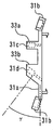
図12はこの発明の実施の形態2における塵埃量検知装置の支持部材の正面図である。図13は図12のB−B線における断面図である。
Next, the support member 31 is demonstrated using FIG. 12 and FIG.
FIG. 12 is a front view of the support member of the dust amount detection device according to Embodiment 2 of the present invention. 13 is a cross-sectional view taken along line BB in FIG.

図12において、支持部材31は、樹脂等で形成される。支持部材31は、平面部31a、ねじ受け部31b、発信部用略筒部31c、受信部用略筒部31dを備える。平面部31aは、略矩形状に形成される。ねじ受け部31bは、平面部31aの端部の少なくとも3箇所に形成される。発信部用略筒部31cは、発信部26aを収容し得るように形成される。受信部用略筒部31dは、受信部26bを収容し得るように形成される。   In FIG. 12, the support member 31 is formed of resin or the like. The support member 31 includes a flat surface portion 31a, a screw receiving portion 31b, a substantially cylindrical portion for transmitting portion 31c, and a substantially cylindrical portion for receiving portion 31d. The plane part 31a is formed in a substantially rectangular shape. The screw receiving portions 31b are formed at at least three positions on the end portion of the flat surface portion 31a. The substantially cylindrical portion 31c for the transmitter is formed so as to accommodate the transmitter 26a. The substantially cylindrical portion 31d for receiving part is formed so as to accommodate the receiving part 26b.

図13に示すように、発信部用略筒部31cの穴の中心線は、平面部31aに対して垂直である。発信部用略筒部31cの穴は、2段形状である。すなわち、発信部用略筒部31cの穴径は、途中で変わる。   As shown in FIG. 13, the center line of the hole of the transmitting portion approximately cylindrical portion 31 c is perpendicular to the flat portion 31 a. The hole of the substantially cylindrical portion 31c for transmitting portion has a two-stage shape. That is, the hole diameter of the substantially cylindrical portion 31c for transmitting portion changes midway.

平面部31a側の穴径は、発信部26aが信号を発信する部位とは反対側の部位の最大径よりも小さい。平面部31a側の穴の底面には、複数の穴が形成される。   The hole diameter on the flat surface portion 31a side is smaller than the maximum diameter of the portion on the side opposite to the portion where the transmitting portion 26a transmits a signal. A plurality of holes are formed on the bottom surface of the hole on the flat surface portion 31a side.

先端部33a側の穴径は、発信部26aの発信する部位とは反対側の部位の最大径よりも大きい。発信部用略筒部31cの穴の中心線に沿って見た際に、先端部33a側の穴の内周面には、回転規制部(図示せず)が形成される。例えば、先端部33a側の穴の内周面には、切り欠き部が形成される。例えば、先端部33a側の穴の内周面には、突き出し部が形成される。例えば、先端部33a側の穴の内周面は平面と曲面とで形成される。   The diameter of the hole on the tip 33a side is larger than the maximum diameter of the part on the opposite side to the part where the transmitting part 26a transmits. A rotation restricting portion (not shown) is formed on the inner peripheral surface of the hole on the tip end portion 33a side when viewed along the center line of the hole of the transmitting portion approximately cylindrical portion 31c. For example, a notch is formed on the inner peripheral surface of the hole on the tip 33a side. For example, a protruding portion is formed on the inner peripheral surface of the hole on the tip portion 33a side. For example, the inner peripheral surface of the hole on the tip end 33a side is formed by a flat surface and a curved surface.

図13に示すように、受信部用略筒部31dの穴の中心線は、平面部31aの垂線に対してγだけ傾斜する。受信部用略筒部31dの穴は、2段形状である。すなわち、受信部用略筒部31dの穴径は、途中で変わる。   As shown in FIG. 13, the center line of the hole of the substantially cylindrical portion 31d for receiving portion is inclined by γ with respect to the perpendicular of the flat portion 31a. The hole of the substantially cylindrical portion for receiving portion 31d has a two-stage shape. That is, the hole diameter of the substantially cylindrical portion 31d for receiving portion changes midway.

平面部31a側の穴径は、受信部26bが信号を受信する部位とは反対側の部位の最大径よりも小さい。平面部31a側の穴の底面には、複数の穴が形成される。   The hole diameter on the flat surface portion 31a side is smaller than the maximum diameter of the portion on the opposite side to the portion where the receiving portion 26b receives a signal. A plurality of holes are formed on the bottom surface of the hole on the flat surface portion 31a side.

先端部33b側の穴径は、受信部26bの受信する部位とは反対側の部位の最大径よりも大きい。受信部用略筒部31dの穴の中心線に沿って見た際に、先端部33b側の穴の内周面には、回転規制部(図示せず)が形成される。例えば、先端部33b側の穴の内周面には、切り欠き部が形成される。例えば、先端部33b側の穴の内周面には、突き出し部が形成される。例えば、先端部33b側の穴の内周面が平面と曲面とで形成される。   The hole diameter on the distal end portion 33b side is larger than the maximum diameter of the portion on the opposite side to the portion received by the receiving portion 26b. A rotation restricting portion (not shown) is formed on the inner peripheral surface of the hole on the distal end portion 33b side when viewed along the center line of the hole of the substantially cylindrical portion 31d for receiving portion. For example, a notch is formed on the inner peripheral surface of the hole on the tip 33b side. For example, a protruding portion is formed on the inner peripheral surface of the hole on the tip end portion 33b side. For example, the inner peripheral surface of the hole on the tip portion 33b side is formed by a flat surface and a curved surface.

次に、図14を用いて、発信部26aを説明する。
図14はこの発明の実施の形態2における塵埃量検知装置の発信部の斜視図である。
Next, the transmission part 26a is demonstrated using FIG.
FIG. 14 is a perspective view of a transmission portion of the dust amount detection device according to Embodiment 2 of the present invention.

図14において、発信部26aは、発光ダイオードである。発信部26aの信号を発信する部位とは反対側には、複数のリード線34が設けられる。発信部26aは、基板26cとの接合に関して極性を有する。   In FIG. 14, the transmitter 26a is a light emitting diode. A plurality of lead wires 34 are provided on the side opposite to the portion that transmits the signal of the transmitter 26a. The transmitter 26a has polarity with respect to the bonding with the substrate 26c.

なお、受信部26bは、光センサである。受信部26bの信号を受信する部位とは反対側には、複数のリード線34が設けられる。受信部26bは、基板26cとの接合に関して極性を有する。   The receiving unit 26b is an optical sensor. A plurality of lead wires 34 are provided on the side opposite to the part that receives the signal of the receiving unit 26b. The receiving unit 26b has polarity with respect to the bonding with the substrate 26c.

次に、図15を用いて、発信部26aに取り付ける部材を説明する。
図15はこの発明の実施の形態2における塵埃量検知装置の回転制約部材の斜視図である。
Next, the member attached to the transmission part 26a is demonstrated using FIG.
FIG. 15 is a perspective view of a rotation restricting member of the dust amount detection device according to Embodiment 2 of the present invention.

図15において、回転制約部材35は、発信部26aのリード線34の本数分の穴を有する。当該穴の径は、発信部26aのリード線34の外径よりも大きい。回転制約部材35の外周面は、発信部用略筒部31cの内周面に対応するように形成される。例えば、回転制約部材35は、発信部26aが発信する信号の中心部を垂線とする面の回転方向の一部に切り欠き部を備える。例えば、回転制約部材35は、発信部26aが発信する信号の中心部を垂線とする面の回転方向の一部に突き出し部を備える。例えば、回転制約部材35は、発信部26aが発信する信号の中心部を垂線とする面の外周が直線と曲線との組み合せとなるように形成される。   In FIG. 15, the rotation restricting member 35 has holes corresponding to the number of the lead wires 34 of the transmitting portion 26a. The diameter of the hole is larger than the outer diameter of the lead wire 34 of the transmitting portion 26a. The outer peripheral surface of the rotation restricting member 35 is formed so as to correspond to the inner peripheral surface of the transmission portion substantially cylindrical portion 31c. For example, the rotation restricting member 35 includes a notch portion in a part of the rotation direction of the surface having a perpendicular to the center portion of the signal transmitted from the transmitting portion 26a. For example, the rotation restricting member 35 includes a protruding portion at a part in the rotation direction of a surface having a perpendicular to the central portion of the signal transmitted from the transmitting portion 26a. For example, the rotation restricting member 35 is formed such that the outer periphery of the surface having a perpendicular to the center of the signal transmitted from the transmitting unit 26a is a combination of a straight line and a curved line.

なお、受信部26bに取り付ける部材も、同様の回転制約部材35である。回転制約部材35は、受信部26bのリード線34の本数分の穴を有する。当該穴の径は、受信部26bのリード線34の外径よりも大きい。回転制約部材35の外周面は、受信部用略筒部31dの内周面に対応するように形成される。例えば、回転制約部材35は、受信部26bが受信する信号の中心部を垂線とする面の回転方向の一部に切り欠き部を備える。例えば、回転制約部材35は、受信部26bが受信する信号の中心部を垂線とする面の回転方向の一部に突き出し部を備える。例えば、回転制約部材35は、受信部26bが受信する信号の中心部を垂線とする面の外周が直線と曲線との組み合せとなるように形成される。   The member attached to the receiving unit 26b is the same rotation restricting member 35. The rotation restricting member 35 has holes for the number of lead wires 34 of the receiving unit 26b. The diameter of the hole is larger than the outer diameter of the lead wire 34 of the receiving portion 26b. The outer peripheral surface of the rotation restricting member 35 is formed so as to correspond to the inner peripheral surface of the receiving portion substantially cylindrical portion 31d. For example, the rotation restricting member 35 includes a notch in a part of the rotation direction of the surface having a perpendicular to the center of the signal received by the receiving unit 26b. For example, the rotation restricting member 35 includes a protruding portion at a part in the rotation direction of a surface having a perpendicular to the central portion of the signal received by the receiving unit 26b. For example, the rotation restricting member 35 is formed so that the outer periphery of the surface having a perpendicular to the center of the signal received by the receiving unit 26b is a combination of a straight line and a curved line.

次に、図16〜図20を用いて、塵埃検知ユニット26の組立手順を説明する。
図16はこの発明の実施の形態2における塵埃量検知装置の回転制約部材を発信部に取り付けた際の側面図である。図17はこの発明の実施の形態2における塵埃量検知装置の支持部材に基板を取り付ける際の側面図である。図18はこの発明の実施の形態2における塵埃量検知装置の基板に発信部と受信部とを接合する直前の側面図である。図19はこの発明の実施の形態2における塵埃量検知装置の基板に発信部と受信部とを接合した直後の側面図である。図20はこの発明の実施の形態2における塵埃量検知装置の支持部材を掃除機本体に取り付ける際の側面図である。
Next, the assembly procedure of the dust detection unit 26 will be described with reference to FIGS.
FIG. 16: is a side view at the time of attaching the rotation restricting member of the dust amount detection apparatus in Embodiment 2 of this invention to the transmission part. FIG. 17 is a side view when the substrate is attached to the support member of the dust amount detection device according to Embodiment 2 of the present invention. FIG. 18 is a side view immediately before joining the transmitter and receiver to the substrate of the dust amount detection apparatus according to Embodiment 2 of the present invention. FIG. 19 is a side view immediately after the transmitter and the receiver are joined to the substrate of the dust amount detection device according to the second embodiment of the present invention. FIG. 20 is a side view when the support member of the dust amount detection device according to Embodiment 2 of the present invention is attached to the cleaner body.

図16に示すように、発信部26aのリード線34が回転制約部材35の穴に挿入される。その結果、発信部26aの信号を発信する部位とは反対側の部位が回転制約部材35の一面に接する。同様に、受信部26bのリード線が回転制約部材の穴に挿入される。その結果、受信部26bの信号を受信する部位とは反対側の部位が回転制約部材の一面に接する。   As shown in FIG. 16, the lead wire 34 of the transmitter 26 a is inserted into the hole of the rotation restricting member 35. As a result, a portion on the opposite side to the portion that transmits the signal of the transmitting portion 26 a contacts one surface of the rotation restricting member 35. Similarly, the lead wire of the receiving part 26b is inserted into the hole of the rotation restricting member. As a result, the part opposite to the part that receives the signal of the receiving unit 26b contacts one surface of the rotation restricting member.

次に、図17に示すように、基板26cが支持部材31に固定される。図17においては、基板26cは、スナップフィットにより支持部材31に固定される。なお、スナップフィット以外の方法で、基板26cが固定される場合もある。   Next, as shown in FIG. 17, the substrate 26 c is fixed to the support member 31. In FIG. 17, the substrate 26c is fixed to the support member 31 by snap fitting. Note that the substrate 26c may be fixed by a method other than snap-fit.

次に、図18に示すように、発信部26aが回転制約部材35とともに発信部用略筒部31cに挿入される。同様に、受信部26bが回転制約部材35とともに受信部用略筒部31dに挿入される。   Next, as shown in FIG. 18, the transmitter 26 a is inserted into the transmitter cylindrical portion 31 c together with the rotation restricting member 35. Similarly, the receiving portion 26b is inserted into the receiving portion substantially cylindrical portion 31d together with the rotation restricting member 35.

次に、図19に示すように、発信部26aのリード線34が基板26cのスルーホールに挿入される。発信部26aのリード線34と基板26cとは、接合部36により接合される。この際、発信部26aの先端は、発信部用略筒部31cの内部に配置される。同様に、受信部26bのリード線34が基板26cのスルーホールに挿入される。受信部26bのリード線34と基板26cとは、接合部36により接合される。この際、受信部26bの先端は、受信部用略筒部31dの内部に配置される。   Next, as shown in FIG. 19, the lead wire 34 of the transmitter 26a is inserted into the through hole of the substrate 26c. The lead wire 34 of the transmitter 26 a and the substrate 26 c are joined by a joint 36. Under the present circumstances, the front-end | tip of the transmission part 26a is arrange | positioned inside the substantially cylindrical part 31c for transmission parts. Similarly, the lead wire 34 of the receiving unit 26b is inserted into the through hole of the substrate 26c. The lead wire 34 of the receiving portion 26b and the substrate 26c are joined by the joining portion 36. At this time, the distal end of the receiving portion 26b is disposed inside the receiving portion substantially cylindrical portion 31d.

次に、図20に示すように、支持部材31のねじ受け部31bが筐体壁面32のねじボス部32aにねじ等で固定される。次に、判定部27が塵埃検知ユニット26に接続される。   Next, as shown in FIG. 20, the screw receiving portion 31 b of the support member 31 is fixed to the screw boss portion 32 a of the housing wall surface 32 with a screw or the like. Next, the determination unit 27 is connected to the dust detection unit 26.

以上で説明した実施の形態2によれば、発信部26aと受信部26bとは、支持部材31にも保持される。このため、発信部26aと受信部26bがより確実に保持される。   According to the second embodiment described above, the transmitting unit 26 a and the receiving unit 26 b are also held by the support member 31. For this reason, the transmission part 26a and the receiving part 26b are hold | maintained more reliably.

当該塵埃量検知装置の製造は容易である。また、接合部36の亀裂が生じづらい。このため、塵埃量検知装置は、長期間機能する。すなわち、塵埃量検知装置の信頼性を向上することができる。   The manufacture of the dust amount detection device is easy. Further, it is difficult for the joint 36 to crack. For this reason, the dust amount detection device functions for a long time. That is, the reliability of the dust amount detection device can be improved.

当該塵埃量検知装置は、一般的な砲弾型の発光ダイオードや砲弾型の光学センサなどを用いて実現される。すなわち、発信部26aと受信部26bを容易に入手することができる。このため、電気掃除機1の使用者は、塵埃の集積を検知する機能を追加する際に塵埃量検知装置を容易に購入することができる。   The dust amount detection device is realized using a general bullet-type light emitting diode, a bullet-type optical sensor, or the like. That is, the transmitter 26a and the receiver 26b can be easily obtained. For this reason, the user of the vacuum cleaner 1 can easily purchase the dust amount detection device when adding the function of detecting the accumulation of dust.

また、発信部26aと受信部26bとを同一の基板26c上に設置できる。このため、複雑な形状でなくなる。さらに、塵埃量検知装置単体としても省スペース化を図ることができる。   In addition, the transmitter 26a and the receiver 26b can be installed on the same substrate 26c. For this reason, it is not a complicated shape. Furthermore, space saving can be achieved even as a dust amount detection device alone.

なお、発信部用略筒部31cと受信部用略筒部31dとにおいて、穴の径が変わる部分から平面部31aにおろした垂線の長さが互いに異なっていてもよい。また、発信部用略筒部31cと受信部用略筒部31dの少なくとも一方が傾斜していればよい。すなわち、発信部用略筒部31cと受信部用略筒部31dとにおいて、穴の径が変わる面が互いに平行でなくてもよい。例えば、発信部用略筒部31cと受信部用略筒部31dの他方が平面部31aと平行な面に対して垂直に形成された場合、ねじ受け部31bは、平面部31aと平行な平面に対して角度を付けて形成される。この場合、支持部材31を樹脂で成形する場合の金型を簡略化できる。その結果、支持部材31を容易に製造できる。   In addition, in the substantially cylindrical portion 31c for the transmitter and the substantially cylindrical portion 31d for the receiver, the lengths of the perpendicular lines extending from the portion where the diameter of the hole changes to the flat portion 31a may be different from each other. Further, it is sufficient that at least one of the substantially cylindrical portion 31c for transmitter and the substantially cylindrical portion 31d for receiver is inclined. That is, in the substantially cylindrical portion 31c for the transmitter and the substantially cylindrical portion 31d for the receiver, the surfaces where the diameters of the holes change may not be parallel to each other. For example, when the other of the substantially cylindrical portion for transmitting portion 31c and the substantially cylindrical portion for receiving portion 31d is formed perpendicular to a plane parallel to the plane portion 31a, the screw receiving portion 31b is a plane parallel to the plane portion 31a. Is formed at an angle with respect to. In this case, the metal mold | die in the case of shape | molding the supporting member 31 with resin can be simplified. As a result, the support member 31 can be easily manufactured.

また、発信部26aと受信部26bとには、回転制約部材35が取り付けられる。回転制約部材35の外周は、支持部材31の内周面に保持される。このため、発信部用略筒部31cの内部において、発信部26aが信号を発信する方向に沿った軸を中心軸をとして回転することを防止できる。受信部用略筒部31dの内部において、受信部26bが信号を受信する方向に沿った軸を中心軸として回転することを防止できる。その結果、発信部26aと受信部26bとを基板26cに取り付ける際の極性の誤りを防止できる。   Further, a rotation restricting member 35 is attached to the transmission unit 26a and the reception unit 26b. The outer periphery of the rotation restricting member 35 is held on the inner peripheral surface of the support member 31. For this reason, it is possible to prevent the transmitter 26a from rotating about the axis along the direction in which the transmitter 26a transmits a signal as the central axis inside the transmitter cylindrical portion 31c. It is possible to prevent the receiving unit 26b from rotating about the axis along the direction in which the signal is received as the central axis inside the receiving portion substantially cylindrical portion 31d. As a result, it is possible to prevent an error in polarity when the transmitter 26a and the receiver 26b are attached to the substrate 26c.

また、発信部26aの先端は、発信部用略筒部31cの内部に配置される。受信部26bの先端は、受信部用略筒部31dの内部に配置される。この場合、発信部用略筒部31cと受信部用略筒部31dとは、信号を遮断する壁面として機能する。すなわち、発信部26aから受信部26bへ直接到達する信号は遮蔽される。このため、受信部26bで受信した全ての信号強度のうち、本来の機能である塵埃量により変化する信号強度の占める割合が大きくなる。その結果、塵埃の集積に対する検知精度をより向上することができる。   The tip of the transmitter 26a is disposed inside the transmitter cylinder 31c. The tip of the receiving part 26b is disposed inside the receiving part substantially cylindrical part 31d. In this case, the transmitter cylinder 31c and the receiver cylinder 31d function as wall surfaces for blocking signals. That is, a signal that directly reaches the receiving unit 26b from the transmitting unit 26a is blocked. For this reason, the ratio which signal intensity which changes with the amount of dust which is an original function among all the signal intensity received by receiving part 26b becomes large. As a result, the detection accuracy for dust accumulation can be further improved.

また、判定部27が塵埃の集積を検知した旨を表示又音声により使用者に報知する報知手段を備えてもよい。例えば、掃除機本体2又は操作スイッチ8の表示部に塵埃の集積を検知した旨を表示してもよい。この場合、使用者に対し、集塵容器18内の塵埃を捨てることを促すことができる。その結果、集塵容器18内部を清潔に保つことができる。また、使用者に報知する方法として、掃除機の吸込み制御を変化させてもよい。例えば、電動送風機25の回転数を変更させてもよい。   Moreover, you may provide the alerting | reporting means which alert | reports to a user by display or an audio | voice that the determination part 27 detected accumulation of dust. For example, you may display on the display part of the cleaner body 2 or the operation switch 8 that the accumulation of dust was detected. In this case, it is possible to prompt the user to throw away the dust in the dust collecting container 18. As a result, the inside of the dust collecting container 18 can be kept clean. Moreover, you may change the suction control of a cleaner as a method of alert | reporting to a user. For example, the rotational speed of the electric blower 25 may be changed.

なお、集塵方式がサイクロン方式以外の掃除機に対し、実施の形態1及び2の塵埃量検知装置を適用してもよい。   In addition, you may apply the dust amount detection apparatus of Embodiment 1 and 2 with respect to vacuum cleaners other than a cyclone system.

また、電気湯沸かし器の水量検知等、発信部26aと受信部26bとを対向する位置に配置できない装置の内容物を検知する際に、実施の形態1及び2の塵埃量検知装置を適用してもよい。   In addition, when detecting the contents of a device in which the transmitter 26a and the receiver 26b cannot be placed at opposite positions, such as detecting the amount of water in an electric water heater, the dust amount detector of the first and second embodiments may be applied. Good.

1 電気掃除機、 2 掃除機本体、 3 車輪、 4 電源コード、 5 サクションホース、 6 接続パイプ、 7 取手、 8 操作スイッチ、 9 吸引パイプ、 10 吸込口体、 11 ホース接続部、 12 吸引風路、 13 集塵ユニット収容部、 14 収容部材、 15 集塵ユニット、 16 流出口、 17 排気風路、 18 集塵容器、 18a 旋回部、 18b 集塵部、 19 隔壁、 20 排出管、 21 メッシュ部材、 22 フィルタ、 23 排出口、 24 電動送風機収容部、 25 電動送風機、 26 塵埃検知ユニット、 26a 発信部、 26b 受信部、 26c 基板、 27 判定部、 28 反射部、 29 集塵容量限界位置、 30a 発信経路、 30b 受信経路、 31 支持部材、 31a 平面部、 31b ねじ受け部、 31c 発信部用略筒部、 31d 受信部用略筒部、 32 筐体壁面、 32a ねじボス部、 33a、33b 先端部、 34 リード線、 35 回転制約部材、 36 接合部   DESCRIPTION OF SYMBOLS 1 Vacuum cleaner, 2 Vacuum cleaner main body, 3 Wheel, 4 Power cord, 5 Suction hose, 6 Connection pipe, 7 Handle, 8 Operation switch, 9 Suction pipe, 10 Suction port body, 11 Hose connection part, 12 Suction air path , 13 Dust collection unit accommodation part, 14 Accommodation member, 15 Dust collection unit, 16 Outlet, 17 Exhaust air duct, 18 Dust collection container, 18a Swivel part, 18b Dust collection part, 19 Partition, 20 Discharge pipe, 21 Mesh member , 22 filter, 23 discharge port, 24 electric blower housing part, 25 electric blower, 26 dust detection unit, 26a transmission part, 26b reception part, 26c substrate, 27 determination part, 28 reflection part, 29 dust collection capacity limit position, 30a Transmission path, 30b reception path, 31 support member, 31a plane part, 1b screw receiving portion, a substantially cylindrical portion for 31c transmitting unit, 31d receiving unit for a substantially tubular portion 32 housing wall, 32a threaded boss, 33a, 33b tip 34 leads, 35 rotation restriction member, 36 joints

Claims (7)

塵埃を含む空気から塵埃を捕集する集塵容器の外部に設けられた発信部と、
前記発信部の信号を発信する部位とは反対側の部位に接した状態で前記発信部に取り付けられた発信部用回転制約部材と、
前記集塵容器の外部に設けられた受信部と、
前記発信部と前記受信部とを保持した基板と、
前記集塵容器の内部に設けられた反射部と、
前記集塵容器の外部に設けられ、前記発信部が発信した信号が前記反射部で反射して前記受信部で受信されるように、前記発信部用回転制約部材の外周と前記受信部とを保持し、前記基板を保持した支持部材と、
を備えた塵埃量検知装置。
A transmitter provided outside the dust container for collecting dust from air containing dust;
A rotation restricting member for a transmitting part attached to the transmitting part in a state of being in contact with a part opposite to the part transmitting the signal of the transmitting part;
A receiver provided outside the dust container;
A substrate holding the transmitter and the receiver;
A reflecting portion provided inside the dust collecting container;
An outer periphery of the rotation restricting member for the transmitting unit and the receiving unit are provided outside the dust collecting container and are reflected by the reflecting unit and received by the receiving unit. Holding a support member holding the substrate ;
A dust amount detection device comprising:
塵埃を含む空気から塵埃を捕集する集塵容器の外部に設けられた発信部と、
前記集塵容器の外部に設けられた受信部と、
前記受信部の信号を受信する部位とは反対側の部位に接した状態で前記受信部に取り付けられた受信部用回転制約部材と、
前記発信部と前記受信部とを保持した基板と、
前記集塵容器の内部に設けられた反射部と、
前記集塵容器の外部に設けられ、前記発信部が発信した信号が前記反射部で反射して前記受信部で受信されるように、前記発信部と前記受信部用回転制約部材の外周とを保持し、前記基板を保持した支持部材と、
を備えた塵埃量検知装置。
A transmitter provided outside the dust container for collecting dust from air containing dust;
A receiver provided outside the dust container;
A rotation restricting member for a receiving unit attached to the receiving unit in contact with a part opposite to the part receiving the signal of the receiving unit;
A substrate holding the transmitter and the receiver;
A reflecting portion provided inside the dust collecting container;
The transmitting unit and the outer periphery of the rotation restricting member for the receiving unit are provided outside the dust collecting container so that the signal transmitted by the transmitting unit is reflected by the reflecting unit and received by the receiving unit. Holding a support member holding the substrate ;
A dust amount detection device comprising:
前記支持部材は、前記発信部の信号を発信する部位とは反対側の部位に接する面と前記受信部の信号を受信する部位とは反対側の部位に接する面とが同一でなく平行でないように形成された請求項1又は請求項に記載の塵埃量検知装置。 In the support member, the surface that contacts the portion opposite to the portion that transmits the signal of the transmitting portion and the surface that contacts the portion opposite to the portion that receives the signal of the receiving portion are not the same and are not parallel. The dust amount detection device according to claim 1 or 2 , wherein the dust amount detection device is formed on the surface. 前記発信部と前記受信部とは、互いを結ぶ線が前記集塵容器の高さ方向の中心線と平行になるように配置された請求項1〜請求項のいずれか一項に記載の塵埃量検知装置。 The originating wherein the receiving portion includes a portion, the line connecting the each other according to any one of the dust collection container in the height direction of the center line and arranged in parallel claims 1 to 3 Dust amount detection device. 前記支持部材は、前記発信部と前記受信部とを結ぶ直線上に設けられ、信号を遮断する壁面を備えた請求項1〜請求項のいずれか一項に記載の塵埃量検知装置。 The dust amount detection device according to any one of claims 1 to 4 , wherein the support member is provided on a straight line connecting the transmitting unit and the receiving unit, and includes a wall surface that blocks a signal. 請求項1〜請求項のいずれか一項に記載の塵埃量検知装置を備えた電気掃除機。 The vacuum cleaner provided with the dust amount detection apparatus as described in any one of Claims 1-5 . 前記受信部が受信した信号の強度に基づいて、前記集塵容器の塵埃の集積を検知する請求項1〜請求項のいずれか一項に記載の塵埃量検知装置と、
前記塵埃量検知装置による塵埃の集積の検知を報知する報知手段と、
を備えた電気掃除機。
The dust amount detection device according to any one of claims 1 to 5 , wherein the dust collection detector detects dust accumulation in the dust collecting container based on the intensity of the signal received by the receiving unit.
Informing means for informing detection of dust accumulation by the dust amount detection device;
Vacuum cleaner with
JP2013037097A 2013-02-27 2013-02-27 Dust amount detection device and vacuum cleaner using the same Expired - Fee Related JP5686149B2 (en)

Priority Applications (1)

Application Number Priority Date Filing Date Title
JP2013037097A JP5686149B2 (en) 2013-02-27 2013-02-27 Dust amount detection device and vacuum cleaner using the same

Applications Claiming Priority (1)

Application Number Priority Date Filing Date Title
JP2013037097A JP5686149B2 (en) 2013-02-27 2013-02-27 Dust amount detection device and vacuum cleaner using the same

Publications (2)

Publication Number Publication Date
JP2014161611A JP2014161611A (en) 2014-09-08
JP5686149B2 true JP5686149B2 (en) 2015-03-18

Family

ID=51612819

Family Applications (1)

Application Number Title Priority Date Filing Date
JP2013037097A Expired - Fee Related JP5686149B2 (en) 2013-02-27 2013-02-27 Dust amount detection device and vacuum cleaner using the same

Country Status (1)

Country Link
JP (1) JP5686149B2 (en)

Family Cites Families (8)

* Cited by examiner, † Cited by third party
Publication number Priority date Publication date Assignee Title
DE4014443A1 (en) * 1990-05-05 1991-11-07 Duepro Ag LIQUID SUCTION
GB9917922D0 (en) * 1999-07-31 1999-09-29 Notetry Ltd Vacuum cleaner
EP1836941B1 (en) * 2006-03-14 2014-02-12 Toshiba TEC Kabushiki Kaisha Electric vacuum cleaner
JP5153663B2 (en) * 2009-01-16 2013-02-27 三菱電機株式会社 Water level detection device and cooking device
US20100236013A1 (en) * 2009-03-17 2010-09-23 Electrolux Home Care Products, Inc. Vacuum Cleaner Sensor
SE534962C2 (en) * 2010-06-29 2012-02-28 Electrolux Ab Dust detection system for a vacuum cleaner
JP4900520B1 (en) * 2011-03-31 2012-03-21 三菱電機株式会社 Vacuum cleaner
JP2014097170A (en) * 2012-11-14 2014-05-29 Mitsubishi Electric Corp Vacuum cleaner

Also Published As

Publication number Publication date
JP2014161611A (en) 2014-09-08

Similar Documents

Publication Publication Date Title
JP4900520B1 (en) Vacuum cleaner
US7921506B2 (en) Robot cleaner having function for detecting separation of dust tank and control method thereof
CN102984981B (en) For the dust indicator of vacuum cleaner
KR100818740B1 (en) Robot cleaner and control method accordingly
JP2014204984A (en) Sensor module and robot cleaner including the same
EP2587979B1 (en) Dust detection system
CN102440718A (en) Dust inflow sensing unit and robot cleaner having the same
US20100236013A1 (en) Vacuum Cleaner Sensor
JP2014161596A (en) Dust detector and vacuum cleaner
JP5686149B2 (en) Dust amount detection device and vacuum cleaner using the same
JP5920191B2 (en) Electric vacuum cleaner
KR102487266B1 (en) Dust detection module and vacuum cleaner comprising the same
KR101710397B1 (en) Cleaner
KR101851587B1 (en) Sensor assembly for robot cleaner
JP2014097170A (en) Vacuum cleaner
JPH1094499A (en) Electric vacuum cleaner
US20240008703A1 (en) Vacuum cleaner and method for controlling thereof
KR20040110822A (en) Automatic robot vacuum cleaner and the Method for controlling the thereof
JP5741632B2 (en) Dust detection device and vacuum cleaner equipped with the same
JP2007122327A (en) Self-propelled vacuum cleaner
JP2022177030A (en) Separator
JP5257465B2 (en) Electric vacuum cleaner
KR102332241B1 (en) Cleaning robot and controlling method thereof
CN114098524A (en) Floor sweeping robot
JP5901454B2 (en) Electric vacuum cleaner

Legal Events

Date Code Title Description
A131 Notification of reasons for refusal

Free format text: JAPANESE INTERMEDIATE CODE: A131

Effective date: 20140902

A521 Request for written amendment filed

Free format text: JAPANESE INTERMEDIATE CODE: A523

Effective date: 20141008

A131 Notification of reasons for refusal

Free format text: JAPANESE INTERMEDIATE CODE: A131

Effective date: 20141118

A521 Request for written amendment filed

Free format text: JAPANESE INTERMEDIATE CODE: A523

Effective date: 20141203

TRDD Decision of grant or rejection written
A01 Written decision to grant a patent or to grant a registration (utility model)

Free format text: JAPANESE INTERMEDIATE CODE: A01

Effective date: 20141224

A61 First payment of annual fees (during grant procedure)

Free format text: JAPANESE INTERMEDIATE CODE: A61

Effective date: 20150106

R150 Certificate of patent or registration of utility model

Ref document number: 5686149

Country of ref document: JP

Free format text: JAPANESE INTERMEDIATE CODE: R150

R250 Receipt of annual fees

Free format text: JAPANESE INTERMEDIATE CODE: R250

R250 Receipt of annual fees

Free format text: JAPANESE INTERMEDIATE CODE: R250

R250 Receipt of annual fees

Free format text: JAPANESE INTERMEDIATE CODE: R250

R250 Receipt of annual fees

Free format text: JAPANESE INTERMEDIATE CODE: R250

R250 Receipt of annual fees

Free format text: JAPANESE INTERMEDIATE CODE: R250

R250 Receipt of annual fees

Free format text: JAPANESE INTERMEDIATE CODE: R250

LAPS Cancellation because of no payment of annual fees