JP5664497B2 - Vehicle front structure - Google Patents
Vehicle front structure Download PDFInfo
- Publication number
- JP5664497B2 JP5664497B2 JP2011174871A JP2011174871A JP5664497B2 JP 5664497 B2 JP5664497 B2 JP 5664497B2 JP 2011174871 A JP2011174871 A JP 2011174871A JP 2011174871 A JP2011174871 A JP 2011174871A JP 5664497 B2 JP5664497 B2 JP 5664497B2
- Authority
- JP
- Japan
- Prior art keywords
- dash panel
- panel
- vehicle
- bottom wall
- cowl
- Prior art date
- Legal status (The legal status is an assumption and is not a legal conclusion. Google has not performed a legal analysis and makes no representation as to the accuracy of the status listed.)
- Expired - Fee Related
Links
- 230000003014 reinforcing effect Effects 0.000 claims description 54
- 238000005452 bending Methods 0.000 claims description 15
- 230000001105 regulatory effect Effects 0.000 claims description 6
- 239000000725 suspension Substances 0.000 description 13
- 230000002787 reinforcement Effects 0.000 description 10
- 238000003466 welding Methods 0.000 description 10
- 229910000831 Steel Inorganic materials 0.000 description 9
- 230000000052 comparative effect Effects 0.000 description 9
- 239000010959 steel Substances 0.000 description 9
- 238000013016 damping Methods 0.000 description 8
- 230000006872 improvement Effects 0.000 description 7
- 238000009434 installation Methods 0.000 description 3
- 239000013256 coordination polymer Substances 0.000 description 2
- 230000008878 coupling Effects 0.000 description 2
- 238000010168 coupling process Methods 0.000 description 2
- 238000005859 coupling reaction Methods 0.000 description 2
- 238000010586 diagram Methods 0.000 description 2
- 230000000694 effects Effects 0.000 description 2
- 230000009466 transformation Effects 0.000 description 2
- 238000004378 air conditioning Methods 0.000 description 1
- 230000005540 biological transmission Effects 0.000 description 1
- 230000015572 biosynthetic process Effects 0.000 description 1
- 230000008859 change Effects 0.000 description 1
- 239000012141 concentrate Substances 0.000 description 1
- 238000006073 displacement reaction Methods 0.000 description 1
- 238000004299 exfoliation Methods 0.000 description 1
- 239000011521 glass Substances 0.000 description 1
- 238000011900 installation process Methods 0.000 description 1
- 239000012212 insulator Substances 0.000 description 1
- 238000000034 method Methods 0.000 description 1
- 230000002093 peripheral effect Effects 0.000 description 1
- 230000008569 process Effects 0.000 description 1
- 238000000926 separation method Methods 0.000 description 1
- 230000003584 silencer Effects 0.000 description 1
Images


Classifications
-
- B—PERFORMING OPERATIONS; TRANSPORTING
- B62—LAND VEHICLES FOR TRAVELLING OTHERWISE THAN ON RAILS
- B62D—MOTOR VEHICLES; TRAILERS
- B62D25/00—Superstructure or monocoque structure sub-units; Parts or details thereof not otherwise provided for
- B62D25/08—Front or rear portions
- B62D25/14—Dashboards as superstructure sub-units
- B62D25/145—Dashboards as superstructure sub-units having a crossbeam incorporated therein
-
- B—PERFORMING OPERATIONS; TRANSPORTING
- B62—LAND VEHICLES FOR TRAVELLING OTHERWISE THAN ON RAILS
- B62D—MOTOR VEHICLES; TRAILERS
- B62D21/00—Understructures, i.e. chassis frame on which a vehicle body may be mounted
- B62D21/09—Means for mounting load bearing surfaces
-
- B—PERFORMING OPERATIONS; TRANSPORTING
- B62—LAND VEHICLES FOR TRAVELLING OTHERWISE THAN ON RAILS
- B62D—MOTOR VEHICLES; TRAILERS
- B62D25/00—Superstructure or monocoque structure sub-units; Parts or details thereof not otherwise provided for
- B62D25/08—Front or rear portions
- B62D25/081—Cowls
Landscapes
- Engineering & Computer Science (AREA)
- Chemical & Material Sciences (AREA)
- Combustion & Propulsion (AREA)
- Transportation (AREA)
- Mechanical Engineering (AREA)
- Body Structure For Vehicles (AREA)
Description
本発明は、ダッシュパネルとカウルとが接合された車両前部構造に関する。 The present invention relates to a vehicle front structure in which a dash panel and a cowl are joined.
カウル後壁に全長に亘り設けられた第1のリインフォースメントと、カウル前壁に接合されたダッシュパネルとを、車幅方向中央部で第2のリインフォースメントにて連結した構成が知られている(例えば、特許文献1参照)。また、カウル前壁に接合されたダッシュパネルの開口部に対する車幅方向両側で該ダッシュパネルに固定された一対のパッチに、一端がカウル後壁に接合されたブレースの他端を接合した構造が知られている(例えば、特許文献2参照)。さらに、車幅方向の中央部において、カウル底壁に上下重ね合わせ状態で接合されたダッシュパネルの背面とカウル後壁とを連結するブレースを備えた自動車の車体前部構造が知られている(例えば、特許文献3参照)。 A configuration is known in which the first reinforcement provided over the entire length of the rear wall of the cowl and the dash panel joined to the front wall of the cowl are connected by the second reinforcement at the center in the vehicle width direction. (For example, refer to Patent Document 1). Also, a structure in which the other end of the brace whose one end is joined to the rear wall of the cowl is joined to a pair of patches fixed to the dash panel on both sides in the vehicle width direction with respect to the opening of the dash panel joined to the front wall of the cowl. It is known (see, for example, Patent Document 2). Further, there is known a vehicle body front structure including a brace that connects a rear surface of a dash panel joined to a cowl bottom wall in a vertically superposed state and a cowl rear wall at a center portion in a vehicle width direction ( For example, see Patent Document 3).
ところで、ダッシュパネルとカウルとの前後方向に重ね合わされた接合部には、車輪からの入力により剥離方向の変形が生じるため、該ダッシュパネルとカウルとの接合部の剥離に対する強度の向上に関し改善の余地がある。 By the way, in the joint portion where the dash panel and the cowl are overlapped in the front-rear direction, deformation in the peeling direction occurs due to the input from the wheel, so that the improvement in the strength against peeling of the joint portion between the dash panel and the cowl is improved. There is room.
本発明は、ダッシュパネルとカウルとの前後方向に重ね合わされた接合部の剥離に対する強度を向上することができる車両前部構造を得ることが目的である。 An object of the present invention is to obtain a vehicle front portion structure that can improve the strength against peeling of a joint portion overlapped in the front-rear direction of a dash panel and a cowl.
請求項1記載の発明に係る車両前部構造は、少なくとも前壁と、該前壁の下端から車両後方に延びる底壁とを有し、車両上向きに開口するカウルパネルと、上端部において前記カウルパネルの前壁に車両前後方向に重ね合わされた状態で車幅方向に亘って接合され、車幅方向に離間して形成された一対の折り曲げ部を有するダッシュパネルと、下端側が前記ダッシュパネルにおける前記一対の折り曲げ部の間に配置された複数の主接合部及び前記一対の折り曲げ部を車幅方向に挟むように配置された少なくとも2箇所の副接合部を含む部分において該ダッシュパネルに接合されると共に、上端側が前記カウルパネルの底壁における車幅方向の位置が異なる複数箇所で接合され、側面視で前記ダッシュパネル及び底壁とで閉断面を構成する補強部材と、を備え、前記補強部材における前記ダッシュパネル及び前記カウルパネルの底壁とで閉断面を構成する本体部は、車幅方向の一端側が前記ダッシュパネルと前記底壁とを直線状に架け渡す第1縁部とされると共に、車幅方向の他端側が前記ダッシュパネルと前記底壁とを側面視で弧状を成すように架け渡す第2縁部とされ、前記補強部材における前記第2縁部からは、車両前後方向に沿って張り出す補強壁が形成されている。 According to a first aspect of the present invention, a vehicle front portion structure includes at least a front wall and a bottom wall extending rearward from the lower end of the front wall, the cowl panel opening upward in the vehicle, and the cowl at the upper end portion. A dash panel having a pair of bent portions joined to each other in the vehicle width direction in a state of being overlapped with the front wall of the panel in the vehicle front-rear direction, and having a pair of bent portions formed apart from each other in the vehicle width direction; Joined to the dash panel at a portion including a plurality of main joints arranged between the pair of bent parts and at least two sub-joint parts arranged so as to sandwich the pair of bent parts in the vehicle width direction. In addition, the upper end side is joined at a plurality of positions at different positions in the vehicle width direction on the bottom wall of the cowl panel, and the reinforcement forms a closed cross section with the dash panel and the bottom wall in a side view. Comprising a timber, a body portion constituting a closed cross section between the in the reinforcing member dash panel and the bottom wall of the cowl panel hung on one side of the vehicle width direction linearly and the dash panel and the bottom wall A second edge portion that bridges the dash panel and the bottom wall so as to form an arc shape in a side view, and the second edge portion of the reinforcing member. From the edge, a reinforcing wall is formed that extends along the vehicle longitudinal direction .
請求項1記載の車両前部構造では、カウルパネルの前壁とダッシュパネルの上端側との前後方向に重ね合わされた接合部を跨ぐようにして、補強部材がダッシュパネルとカウルパネルの底壁とを架け渡している。そして、ダッシュパネルと底壁と補強部材とで側面視で閉断面が形成されている。この構成により、ダッシュパネルとカウルパネルとの前後に重ね合わされた接合部の剥離方向の変形(荷重)が、補強部材の引張りにて規制(支持)される。
In the vehicle front structure according to
このように、請求項1記載の車両前部構造では、ダッシュパネルとカウルパネルとの前後方向に重ね合わされた接合部の剥離に対する強度を向上することができる。特に、補強部材がない場合に剥離に対する強度が相対的に低くなる車幅方向の位置に補強部材を設けることで、車幅方向の広範囲に亘り補強部材を設ける構成と比べて、効率的にダッシュパネルとカウルパネルとの接合部の剥離に対する強度を向上することができる。 Thus, in the vehicle front structure according to the first aspect, it is possible to improve the strength against peeling of the joint portion overlapped in the front-rear direction of the dash panel and the cowl panel. In particular, when there is no reinforcing member, the reinforcing member is provided at a position in the vehicle width direction where the strength against peeling is relatively low, so that it is more efficient than the configuration in which the reinforcing member is provided over a wide range in the vehicle width direction. The strength against peeling of the joint between the panel and the cowl panel can be improved.
また、本車両前部構造では、ダッシュパネルの折り曲げ部は高剛性部とされ、車輪からの入力をカウルパネルとの接合部に伝えやすい。すなわち、ダッシュパネルにおける一対の折り曲げ部に挟まれた領域の車両上方では、補強部材がない場合に剥離に対する強度が相対的に低い(応力が集中しやすい)部分とされる。この一対の折り曲げ部間に配置された主接合部において補強部材の下端側がダッシュパネルに接合されているため、車幅方向に局所的に配置される補強部材によって、ダッシュパネルとカウルパネルとの接合部の剥離に対する強度を向上することができる。しかも、補強部材は、複数の主接合部を有するので、主接合部が1つの構成と比べて、該補強部材とダッシュパネルとの接合部位に生じる応力も緩和される。 Moreover, in this vehicle front part structure, the bent part of the dash panel is a high-rigidity part, and the input from the wheel is easily transmitted to the joint part with the cowl panel. That is, above the vehicle in a region sandwiched between the pair of bent portions in the dash panel, the strength against peeling is relatively low (stress is likely to concentrate) when there is no reinforcing member. Since the lower end side of the reinforcing member is joined to the dash panel at the main joining portion arranged between the pair of bent portions, the dash panel and the cowl panel are joined by the reinforcing member locally arranged in the vehicle width direction. The strength against peeling of the part can be improved. In addition, since the reinforcing member has a plurality of main joint portions, the stress generated at the joint portion between the reinforcing member and the dash panel is also reduced as compared with a configuration in which the main joint portion is one.
また、本車両前部構造では、一対の折り曲げ部を車幅方向の両側から挟むように配置される複数の副接合部によって、主接合部の接合前に、補強部材のダッシュパネルに対する位置ずれを抑制することができる。これにより、主接合部をダッシュパネルに対する所要の位置で適正に接合することができ、該主接合部においてダッシュパネルとカウルパネルとの接合部の剥離に対する強度の向上に寄与させることができる。
また、本車両前部構造では、補強部材が複数箇所でカウルパネルの底壁に接合されているので、該接合部位が1つの構成と比べて、該補強部材とカウルパネルとの接合部位に生じる応力も緩和される。
また、本車両前部構造では、補強部材は第1縁部側でダッシュパネルとカウルパネルの底壁とを直線状に架け渡し、第2縁部側ではダッシュパネルとカウルパネルの底壁とを側面視で(前後何れかに凸となるように)弧状を成すように架け渡す。この第2縁部側では、第1縁部側と比べて、補強部材とダッシュパネル及びカウルパネルとの距離が近づくか遠ざかることとなる。このため、補強部材と他の部品との干渉を避けた構造とすることができる。ここで、弧状を成す第2縁部は、引張りによる補強には不利となりやすいが、該第2縁部から前後方向に張り出された補強壁により引張りに対し補強される。したがって、補強部材による所要の補強機能を果たすことに寄与する。
Further, in the vehicle front structure, the position of the reinforcing member relative to the dash panel is shifted before joining the main joint by the plurality of sub-joints arranged so as to sandwich the pair of bent parts from both sides in the vehicle width direction. Can be suppressed. Thereby, a main junction part can be joined appropriately in a required position with respect to a dash panel, and it can contribute to the improvement in the strength to exfoliation of a junction part of a dash panel and a cowl panel in this main junction part.
Moreover, in this vehicle front part structure, since the reinforcing member is joined to the bottom wall of the cowl panel at a plurality of locations, the joining portion is generated at the joining portion of the reinforcing member and the cowl panel as compared with one configuration. Stress is also relieved.
In the vehicle front structure, the reinforcing member extends between the dash panel and the bottom wall of the cowl panel in a straight line on the first edge side, and the dash panel and the bottom wall of the cowl panel on the second edge side. It is bridged in an arc shape in a side view (so that it is convex in the front or back). On the second edge side, the distance between the reinforcing member, the dash panel, and the cowl panel is closer to or farther than that on the first edge side. For this reason, it can be set as the structure which avoided interference with a reinforcement member and other components. Here, the arc-shaped second edge portion tends to be disadvantageous for reinforcement by tension, but is reinforced against tension by a reinforcing wall protruding in the front-rear direction from the second edge portion. Therefore, it contributes to fulfilling a required reinforcing function by the reinforcing member.
請求項2記載の発明に係る車両前部構造は、請求項1記載の端部構造において、前記副接合部は、前記補強部材の下端側から車幅方向の両側に張り出された一対の脚部に形成されている。 According to a second aspect of the present invention, there is provided the vehicle front portion structure according to the first aspect , wherein the sub-joining portion is a pair of legs projecting from the lower end side of the reinforcing member to both sides in the vehicle width direction. It is formed in the part.
請求項2記載の車両前部構造では、補強部材の下部から張り出された脚部に副接合部が形成されているので、補強部材の大型化を抑えながら、一対の折り曲げ部に挟まれた面を挟む両側に副接合部を配置する構成を得ることができる。
In the vehicle front structure according to
請求項3記載の発明に係る車両前部構造は、請求項1又は請求項2記載の端部構造において、前記補強部材は、前記ダッシュパネル及び前記カウルパネルの底壁とで閉断面を構成する本体部と、前記本体部の下端で屈曲されると共に前記ダッシュパネルの背面に沿って延出され該ダッシュパネルに接合された下フランジと、前記本体部の上端で屈曲されると共に前記底壁の下面に沿って延出され該底壁に接合された上フランジと、前記本体部と前記下フランジとの屈曲角を広げる方向の変形を規制する下側規制部と、前記本体部と前記上フランジとの屈曲角を広げる方向の変形を規制する上側規制部とを含んで構成されている。 According to a third aspect of the present invention, in the vehicle front portion structure according to the first or second aspect , the reinforcing member forms a closed cross section with the dash panel and the bottom wall of the cowl panel. A main body, a lower flange that is bent at the lower end of the main body and extends along the back surface of the dash panel, and is bent at the upper end of the main body and is bent at the upper end of the main body. An upper flange that extends along the lower surface and is joined to the bottom wall, a lower regulating portion that regulates deformation in a direction in which a bending angle between the main body portion and the lower flange is widened, and the main body portion and the upper flange And an upper restricting portion that restricts deformation in a direction in which the bending angle is widened.
請求項3記載の車両前部構造では、補強部材における本体部と上フランジ、下フランジとの間がそれぞれ屈曲されており、補強部材に引張り荷重が作用すると、各屈曲部位の屈曲角を広げる(各屈曲部位を展開させる)方向の変形が生じる。ここで、補強部材における本体部と上フランジ、下フランジとの間には、上側規制部、下側規制部が形成されている。このため、補強部材における上下の屈曲部位を展開させる方向の変形が規制(制限)され、補強部材の引張りによってダッシュパネルとカウルパネルとの接合部の剥離に効率的に抗することができる。 In the vehicle front structure according to the third aspect , the main body portion of the reinforcing member and the upper flange and the lower flange are bent, and when a tensile load acts on the reinforcing member, the bending angle of each bent portion is widened ( Deformation in the direction in which each bending portion is developed occurs. Here, an upper restricting portion and a lower restricting portion are formed between the main body portion and the upper flange and the lower flange in the reinforcing member. For this reason, the deformation | transformation of the direction which expands the upper and lower bending part in a reinforcement member is controlled (restricted), and it can resist effectively peeling of the junction part of a dash panel and a cowl panel by the tension | pulling of a reinforcement member.
請求項4記載の発明に係る車両前部構造は、請求項1〜請求項3の何れか1項記載の端部構造において、前記補強部材における前記ダッシュパネル及び前記カウルパネルの底壁とで閉断面を構成する中間部分には、複数の開口部が形成されている。 According to a fourth aspect of the present invention, there is provided the vehicle front portion structure according to any one of the first to third aspects, wherein the vehicle is closed by the dash panel and the bottom wall of the cowl panel in the reinforcing member. A plurality of openings are formed in the intermediate portion constituting the cross section.
請求項4記載の車両前部構造では、補強部材の本体部に複数の開口部が形成されており、該複数の開口部を利用して補強部材の姿勢を所要の姿勢に保持することができる。すなわち、補強部材をダッシュパネル及びカウルパネルに対する適正な姿勢で該ダッシュパネル及びカウルパネルに接合することができる。これにより、主接合部をダッシュパネルに対する所要の姿勢で適正に接合することができ、該主接合部においてダッシュパネルとカウルパネルとの接合部の剥離に対する強度の向上に寄与させることができる。 In the vehicle front portion structure according to claim 4 , a plurality of openings are formed in the main body of the reinforcing member, and the posture of the reinforcing member can be held in a required posture by using the plurality of openings. . That is, the reinforcing member can be joined to the dash panel and the cowl panel in an appropriate posture with respect to the dash panel and the cowl panel. Thereby, the main joint part can be appropriately joined in a required posture with respect to the dash panel, and the main joint part can contribute to improvement in strength against peeling of the joint part between the dash panel and the cowl panel.
以上説明したように本発明に係る車両前部構造は、ダッシュパネルとカウルパネルとの前後方向に重ね合わされた接合部の剥離に対する強度を向上することができるという優れた効果を有する。 As described above, the vehicle front structure according to the present invention has an excellent effect that it is possible to improve the strength against peeling of the joint portion overlapped in the front-rear direction of the dash panel and the cowl panel.
本発明の第1の実施形態に係る車両前部構造としての車体前部構造10について、図1〜図6に基づいて説明する。なお、図中に適宜記す矢印FRは車両前後方向の前(進行)方向を、矢印UPは車両上下方向の上方向を、矢印RHは進行方向を向いた場合の右方向(車幅方向一方)側を、矢印LHは進行方向を向いた場合の左方向(車幅方向他方)側をそれぞれ示す。以下の説明で、特記なく前後、上下、左右の方向を用いる場合は、車両前後方向の前後、車両上下方向の上下、進行方向を向いた場合の左右を示すものとする。
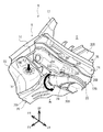
A vehicle
(車体前部の概略構成)
図3には、車体前部構造10が適用された自動車Vを構成する車体Bの右側の一部が斜視図にて示されている。車体Bは、後述する部分を除き基本的に略左右対称に構成されるので、以下の説明では、主に右側(この実施形態では助手席側)について主に説明することとする。この図3に示される如く、車体Bは、フロントピラー12と、フロントピラー12の上下方向中間部から前方に延びるエプロンアッパメンバ14と、エプロンアッパメンバ14から垂下されたエプロンパネル16とを含んで構成されている。また、車体Bを構成するエプロンパネル16には、図示しないフロントサスペションの上端が結合されるフロントサスペンションタワー18が一体に形成されている。
(Schematic configuration of the front part of the vehicle body)
FIG. 3 is a perspective view showing a part of the right side of the vehicle body B constituting the automobile V to which the vehicle
また、車体Bは、前後方向に延在する骨格部材としてのフロントサイドメンバ20を含んで構成されている。フロントサイドメンバ20の図示しない前端には、バンパリインフォースメントの車幅方向一端側が結合されている。フロントサイドメンバ20は、エンジンルームE内で前後に延びる前部20Fと、後述のダッシュパネル22に沿って曲げられたキック部20Kと、キック部20Kの後方で図示しないフロアパネルとで前後に長い骨格を成す後部20Rとを含んで構成されている。フロントサイドメンバ20の前部20Fは、その後部がフロントサスペンションタワー18の車幅方向の内側部分に接合されている。
The vehicle body B includes a
さらに、車体Bは、エンジンルームEと車室Cとを隔てるダッシュパネル22を備えている。ダッシュパネル22は、その下端側が車幅方向の略全長に亘って図示しないフロアパネルの前端に接合されている。また、ダッシュパネル22の前面側には、該ダッシュパネル22とで閉断面の骨格構造を成すダッシュクロスメンバ24が車幅方向の略全長に亘って接合されている。フロントサイドメンバ20の前部20Fの後端は、ダッシュクロスメンバ24に突き当て状態で接合されている。また、フロントサイドメンバ20のキック部20Kは、ダッシュパネル22の前面に接合され、フロアパネルの下面に接合された後部20Rに連続している。
Further, the vehicle body B includes a
一方、ダッシュパネル22の上端側は、カウル部26を構成するカウルパネル28が接合されている。カウルパネル28は、上向きに開口する断面略ハット形状でかつ車幅方向に長手の部材であり、左右のフロントピラー12の上下方向中間部間を架け渡している。また、カウルパネル28の長手方向両端は、左右対応する側のエプロンアッパメンバ14に接合されている。このカウルパネル28を備えたカウル部26は、左右のフロントピラー12及び図示しないルーフヘッド部とで図示しないウインドシールドガラスを支持する構成とされている。
On the other hand, a
以上説明した車体Bでは、前輪(フロントサスペンション)からの荷重がフロントサスペンションタワー18、フロントピラー12を介して、ダッシュパネル22とカウルパネル28との接合部に該接合の剥離方向の荷重として伝えられる構成とされている。この荷重伝達については、本実施形態の作用と共に説明することとする。
In the vehicle body B described above, the load from the front wheel (front suspension) is transmitted to the joint portion between the
(車体前部構造10の要部の詳細構造)
以下、車体前部構造10の要部について詳細に説明する。
(Detailed structure of the main part of the vehicle body front structure 10)
Hereinafter, the main part of the vehicle
図2に示される如く、カウルパネル28は、前後方向に対向する前壁28F、後壁28R、該前壁28F及び後壁28Rの下端間を繋ぐ底壁28Bを主要部として構成されている。これにより、カウルパネル28は、上記の通り上向き開口している。また、カウルパネル28の前下部においては、前壁28Fの下部及び底壁28Bの前部に側面視で略L字状を成すカウル制振鋼板30がスポット溶接等によって接合されている。より具体的には、カウル制振鋼板30は、前壁28Fに接合された前壁部30Fと、底壁28Bに接合された下壁部30Lとを主要部として構成されている。
As shown in FIG. 2, the
そして、ダッシュパネル22の上端部22Uは、カウルパネル28の前壁28Fに前後方向への重ね合わせ状態で接合されている。この実施形態では、ダッシュパネル22の上端部22Uとカウルパネル28の前壁28Fの下部とは、接合部Jcdにおいて、車幅方向の略全長に亘りカウル制振鋼板30の前壁部30Fを介して接合されている。この実施形態に係る接合部Jcdは、前後方向に3枚重ね合わされた前壁部30F、前壁28F、及び上端部22Uがスポット溶接によって一体的に接合されて構成されている。
The
上記した如く上端部22Uにおいてカウルパネル28に接合されたダッシュパネル22は、運転席側と助手席側とで車室CやエンジンルームEの形状の相違することと等によって、左右非対称形状とされている。そして、図4に示される如く、正面視における車幅方向中心線CLと、右側のフロントサスペンションタワー18におけるフロントサスペンションの結合部18C(仮想線IL1)との間の領域Aにおいて、ダッシュパネル22には段差部22Sが形成されている。すなわち、段差部22Sは、車体Bの車幅方向中央部に対し助手席側にオフセットして配置されている。段差部22Sは、ダッシュパネル22の一般部22Gと、該一般部22Gよりも前方に突出された座面部22Zとを繋ぐ傾斜立壁とされている。
As described above, the
したがって、段差部22Sの右側には、座面部22Zとの境界となる第1稜線RL1が形成され、段差部22Sの左側には、一般部22Gの境界となる第2稜線RL2が形成されている。ダッシュパネル22は、プレス加工により形成されており、第1稜線RL1及び第2稜線RL2は、本発明における一対の折り曲げ部に相当する。なお、この実施形態では、ダッシュパネル22の座面部22Zにおける段差部22Sに近接する部分に、該ダッシュパネル22を貫通する貫通孔22Hが形成されている。
Accordingly, a first ridge line RL1 that is a boundary with the
また、図1に示される如く、この実施形態におけるダッシュパネル22は、背面側から第2ダッシュパネル32にて覆われている。第2ダッシュパネル32は、ダッシュパネル22に接合されて該ダッシュパネル22を補強する構成とされている。なお、全体の図示は省略するが、第2ダッシュパネル32は、ダッシュパネル22のうち段差部22Sの上部及び座面部22Zにおける貫通孔22Hの周辺部分を露出させるほかは、該ダッシュパネル22を略前面に亘り背面側から覆う構成とされている。
Further, as shown in FIG. 1, the
そして、車体前部構造10(車体B)は、ダッシュパネル22とカウルパネル28とを正面視において領域A内の定位置で連結する補強部材としてのパッチ34を備えている。具体的には、図1及び図4に示される如く、パッチ34は、ダッシュパネル22の段差部22Sと、カウルパネル28の底壁28Bとを架け渡している。この実施形態におけるパッチ34は、その下部においてダッシュパネル22の段差部22Sに接合された下フランジ34Lと、その上部においてカウルパネル28における底壁28Bの前部に接合された上フランジ34Uとを有する。
The vehicle body front structure 10 (vehicle body B) includes a
そして、パッチ34における下フランジ34Lと上フランジ34Uとの間に位置する本体部としてのパッチ本体34Mは、図2に示される如く、ダッシュパネル22と、カウルパネル28の底壁28Bとで、側面視で略三角形状の閉断面部CSを形成している。すなわち、パッチ本体34Mは、ダッシュパネル22及びカウルパネル28とは離間されている。以下、パッチ34及びその接合(結合)構造について、より具体的に説明する。
A patch
図5に示される如く、パッチ本体34Mは、板状を成しており、左側の縁部34ELが上下方向に対し若干傾斜した直線状に形成されると共に、右側の縁部ERが後方に凸となるように側面視で湾曲されて弧状を成している。パッチ本体34Mにおける湾曲された右側の縁部34ERからは、補強壁としての補強フランジ34Fが後向きに立設されている。これにより、パッチ本体34Mは、その右側の縁部ERが補強フランジ34Fにて上下(引張り)方向に補強されている。また、パッチ本体34Mには、パッチ34の車体Bへの接合の際に溶接装置の基準ピンが挿入される取付基準孔34Hsと、車体Bへの組付姿勢を維持するための複数の開口部としての一対の治具取付孔34Hjとが形成されている。
As shown in FIG. 5, the
上フランジ34Uは、パッチ本体34Mの上端に対し後方に折り曲げるようにして形成されており、図1に示される左右両端側の2箇所の上側接合部Juにて底壁28Bに接合されている。この実施形態におけるパッチ34における幅方向の中央部には、上フランジ34Uとパッチ本体34Mの上端部とに跨って、後向きに凸となる上側規制部としてのリブ34Rが形成されている。これにより、パッチ34は、リブ34Rが形成されない構成と比較して、パッチ本体34Mと上フランジ34Uとの屈曲角を広げる方向(折り曲げを解消する方向である展開方向)の変形に対し補強されている。また、この実施形態では、上フランジ34Uの右側の縁部ERには、上記した補強フランジ34Fが連続されている。
The
下フランジ34Lは、パッチ本体34Mの下端に対し後方に折り曲げるようにして形成されており、図1に示される複数の主接合部としての上下2箇所の下側主接合部Jlmにて段差部22Sに接合されている。下側主接合部Jlmは、パッチ34下部のダッシュパネル22に対する接合強度を担保する構成とされている。
The
また、パッチ34におけるパッチ本体34Mの下部、下フランジ34Lからは、それぞれ脚部としての一対の張出脚部34P1、34P2が左右の互いに異なる側に張り出されている。右側に張り出された張出脚部34P1は、補強フランジ34Fの下部よりも右側に張り出され、その先端近傍に配置された副接合部としての下側副接合部Jlsにてダッシュパネル22の座面部22Zの背面側に接合されている。一方、パッチ本体34Mの下部及び下フランジ34Lの左端からさらに左方に張り出された34P2は、その先端近傍に配置された副接合部としての下側副接合部Jlsにてダッシュパネル22の一般部22Gの背面側に接合されている。
In addition, a pair of projecting leg portions 34P1 and 34P2 as leg portions project from the left and right sides of the
この実施形態では、張出脚部34P2側は、下側副接合部Jlsにおいて第2ダッシュパネル32を介してダッシュパネル22に接合されている。左右の下側副接合部Jlsは、ダッシュパネル22の段差部22S(パッチ本体34M)を車幅方向に挟む位置で、下側主接合部Jlmの接合前に接合され、パッチ34下部のダッシュパネル22に対する結合位置ずれを許容範囲に収める構成とされている。
In this embodiment, the projecting leg portion 34P2 side is joined to the
また、張出脚部34P2は、下フランジ34Lとの境界部に上向きに凸となる稜線(折り曲げ部)RL3を形成すると共に、パッチ本体34Mの下部との境界部に後向きに凸となる稜線(折り曲げ部)RL4を形成している。これにより、パッチ34は、稜線RL3、RL4が形成されない構成と比較して、パッチ本体34Mと下フランジ34L(及び張出脚部34P2)との屈曲角を広げる方向(折り曲げを解消する方向である展開方向)の変形に対し補強されている。このように張出脚部34P2において下フランジ34Lとの境界部に稜線RL3を形成すると共に、パッチ本体34Mの下部との境界部に稜線RL4を形成した構成が、本発明における下側規制部に相当する。
The overhanging leg portion 34P2 forms a ridge line (folded portion) RL3 that protrudes upward at the boundary portion with the
以上説明したパッチ34とダッシュパネル22、カウルパネル28との各接合部は、スポット溶接による溶接接合とされている。この溶接接合に代えて、ボルト・ナットによる締結を採用することも可能である。
The joints between the
また、車体前部構造10では、図2に示される如く、ダッシュパネル22におけるパッチ34の設置箇所を含む部分に対する車室C側に、ダッシュインナサイレンサ(インシュレータ)、空調ユニット(HVAC)、ワイヤハーネス等の部品CPが配置されている。パッチ34は、これらの各部品CP(ワイヤハーネス等の可動部品の可動領域を含む)との干渉を避けるべく、上記した如くパッチ本体34Mの右縁部が湾曲される如き形状が採用されている。
In the vehicle
(パッチ34の設置工程)
また、車体前部構造10では、車体Bの組み立て過程において、カウル部26が組み付けられる前に、ダッシュパネル22が組み付けられており、この状態からパッチ34が2箇所の下側副接合部Jlsにおいてダッシュパネル22に固定される。次いで、パッチ34が2箇所の下側主接合部Jlmにおいてダッシュパネル22の段差部22Sに固定される。そして、カウル部26が車体Bに組み付けられた後、最終組付工程で、パッチ34は上側接合部Juにおいてカウル制振鋼板30を介してカウルパネル28の底壁28Bに固定される。
(
Further, in the vehicle
この組み付けの際に、パッチ34は、パッチ本体34Mに形成された2つの治具取付孔34Hjにおいて冶具に取り付けられることで、ダッシュパネル22に対する姿勢が保持される。例えば組み立てロボットのロボットハンドに設けられた冶具に治具取付孔34Hjにおいて取り付けられた状態で、該ロボットによってパッチ34は組み立て途中の車体Bの所要位置に搬送(挿入)される。ダッシュパネル22(車体B)に対する所要の位置に搬送されたパッチ34は、その取付基準孔34Hsに溶接用の基準ピンが挿入され、この状態で、上記の通り下側副接合部Jlsにて位置決め固定される。
At the time of this assembly, the posture of the
次に、第1の実施形態の作用を説明する。 Next, the operation of the first embodiment will be described.
例えば自動車の悪路走行時等には、フロントサスペンションに上下方向の大きな荷重が作用する。特に、前輪に大径のタイヤを装着する等ばね下質量の大きな自動車や、ハイブリッド車等の重量物であるバッテリを搭載しバネ上質量の大きな自動車では、フロントサスペンションから車体Bへの荷重が大きくなりやすい。 For example, when the vehicle is traveling on a rough road, a large load in the vertical direction acts on the front suspension. In particular, in an automobile with a large unsprung mass, such as a large-diameter tire mounted on the front wheel, or a vehicle with a large unsprung mass, such as a hybrid vehicle, with a large unsprung mass, the load from the front suspension to the vehicle body B is large. Prone.
そして、上記構成の車体前部構造10が適用された自動車では、フロントサスペンションからフロントサスペンションタワー18に下向きの大荷重が入力される(矢印Fd参照)と、フロントサスペンションタワー18に接合されたフロントサイドメンバ20の前部20Fが下方に押し下げられる。このため、前部20F後端のダッシュクロスメンバ24との接合部分を付け根としてモーメントMが生じ、このモーメントMによってダッシュパネル22が前方に引張られる。
In a vehicle to which the vehicle
すると、前後方向に重ね合わせてスポット溶接されたダッシュパネル22の上端部22Uとカウルパネル28の前壁28Fとの前後重ね合わせの接合部Jcdには、剥離方向の変形(応力)が生じる。特に、左右の前輪が上下逆相で動く場合などには、接合部Jcdに生じる剥離(前後)方向の変形が大きくなりやすい。
Then, deformation (stress) in the peeling direction is generated at the joint portion Jcd of the front and rear overlaps of the
そして、ダッシュパネル22における段差部22Sすなわち2つの稜線RL1、RL2に挟まれた部分は、高剛性部位とされる。このため、フロントサイドメンバ20と段差部22Sとを結ぶ仮想直線に沿って、上記したモーメントMによる車両前方へ引っ張る方向への荷重(変形)が接合部Jcdに伝えられる。換言すれば、2つの稜線RL1、RL2(段差部22S)上の経路では、他の部分よりもモーメントMによる荷重がパネル変形により吸収(減衰)されにくく、他の部分よりも大きな荷重が接合部Jcdに伝えられることとなる。すなわち、ダッシュパネル22の車幅方向の各部において、段差部22Sの形成部位で接合部Jcdに生じる剥離方向の変形が最も大きくなる。数値解析により、パッチ34を備えない比較例では、図4にスポット溶接打点S1〜S3を含む領域Zで高応力になることが確かめられている。
And the
このため、パッチ34を備えない比較例では、図6(B)に示される如く、想像線に示す荷重入力(変形)前の形状に対し、実線にて示す変形状態での接合部Jcd剥離方向の変形量が大きくなる。具体的には、ダッシュパネル22と前壁28Fとの成す角θすなわち繰り返し荷重(応力)が大きくなる。この対策として、接合部Jcdでスポット溶接の剥離が生じない疲労強度を得る(接合部Jcdに作用する応力を緩和する)ようにダッシュパネル22、カウルパネル28を構成する鋼板の板厚を増すと、車体Bの質量が増すこととなる。
Therefore, in the comparative example that does not include the
ここで、車体前部構造10では、ダッシュパネル22における接合部Jcdの剥離方向の変形すなわち応力が最大となる部分にパッチ34を設けた。このため、ダッシュパネル22と前壁28Fとの剥離方向の変形が、パッチ34の略上下方向の引張りによって、規制(変形に抗する荷重が支持)される。図6(A)は、上記図6(B)の比較例と同じ荷重条件とした場合の本実施形態の数値解析結果の概略を示したものである。この図6(A)に示される如く、本実施形態におけるダッシュパネル22と前壁28Fとの成す角θ、すなわち繰り返し荷重(応力)は、実線にて示す変形後の状態において、上記比較例と比較して小さく抑えられる。なお、図6(A)の想像線は、図6(B)の比較例と同様、ダッシュパネル22及びカウルパネル28の荷重入力(変形)前の形状を示している。
Here, in the vehicle
この実施形態においては、段差部22Sの直上で、接合部Jcdのスポット溶接打点に作用する応力が低減されることが、FEM等の数値解析(CAE)によって確かめられている。より具体的には、図4に示す段差部22Sの直上のスポット溶接打点S1〜S3では、作用する応力がそれぞれ低減されるとの解析結果を得た。
In this embodiment, it is confirmed by numerical analysis (CAE) such as FEM that the stress acting on the spot welding spot of the joint Jcd is reduced immediately above the stepped
このように、本実施形態に係る車体前部構造10では、ダッシュパネル22とカウルパネル28との接合部における車幅方向で最も応力集中を生じやすい段差部22Sの形成部位において、剥離に対する強度(疲労強度)を向上することができる。また、パッチ34を設置することで、車体Bでは、自動車Vの旋回やレーンチェンジの際のねじりに対する剛性が向上する。
As described above, in the vehicle
特に、車体前部構造10では、前後方向に接合されたカウルパネル28の前壁28Fとダッシュパネル22の上端部22Uとの接合部Jcdに対し、該接合部Jcd直下のダッシュパネル22と前壁28F近傍の底壁28Bとがパッチ34にて連結されている。すなわち、引張りによってダッシュパネル22とカウルパネル28との接合部Jcdの剥離に抗するパッチ34が、接合部Jcdを跨ぐようにダッシュパネル22とカウルパネル28とを連結する構造とされる。これにより、例えば上端側がカウルパネル28の後壁28R偽都合される如き比較例と比較して、パッチ34によって効率的にダッシュパネルとカウルとの接合部の剥離に対する強度を向上することに寄与する。
In particular, in the vehicle
また、上記構成のパッチ34は、短距離でダッシュパネル22とカウルパネル28とを連結するため、コンパクトなパッチ34によって、ダッシュパネル22と前壁28Fとの成す角θすなわち繰り返し荷重(応力)を小さく抑えることができる。これにより、同等の疲労強度の向上効果をダッシュパネル22及びカウルパネル28の板厚増加にて達成する比較例と比較して、車体Bの質量増加を著しく小さく抑えることができる。なお、パッチを追加する質量増加は、板厚を増加することによる同等の疲労強度を得る比較例に対して質量メリットがあることが数値解析結果により確かめられている。
In addition, since the
特に、パッチ34は、リブ34Rによって上フランジ34Uのパッチ本体34Mに対する展開方向の変形(折り曲げ解消)に対する強度が高められている。また、パッチ34は、稜線RL3、RL4の設定によって下フランジ34Lのパッチ本体34Mに対する展開方向の変形(折り曲げ解消)に対する強度が高められている。すなわち、パッチ34は、上側接合部Juと下側主接合部Jlmとを結ぶ仮想直線IL2(図2参照)に沿った引張りに対し高剛性に構成されており、コンパクトでありながら、上記した疲労強度の向上効果が大きい。また、上下のフランジ34U、34Lの変形規制部が別個に形成されているので、上記屈曲部の補強機能を果たしながら、パッチ34のコンパクト化に寄与する。
In particular, the strength of the
また特に、車体前部構造10では、パッチ本体34Mの車幅方向一方の縁部(右縁部)が湾曲形状とされて、他の部品との干渉が防止されている。このパッチ本体34Mに沿って補強フランジ34Fが立設されているため、該補強フランジ34Fによってパッチ本体34Mは引張りに対する所要の強度が確保される。すなわち、上記の通り接合部Jcdの疲労強度に寄与するのに十分な引張りに対する強度が確保される。この補強フランジ34Fは、上フランジ34Uの右縁部にも連続しているため、上記したリブ34Rと共に上フランジ34Uのパッチ本体34Mに対する展開方向の折り曲げに対する強度の向上にも寄与している。
In particular, in the vehicle body
一方、車体前部構造10では、段差部22Sに複数(2箇所)の下側主接合部Jlmが設定されている。このため、下側主接合部Jlmが1つである構成と比較して、下側主接合部Jlmでの応力を緩和することができる。換言すれば、ダッシュパネル22とパッチ34との接合部位における車輪から伝達される荷重が複数の下側主接合部Jlmに分散され、各下側主接合部Jlmの応力が小さく抑えられる。
On the other hand, in the vehicle
同様に、パッチ34の上フランジ34Uが複数の上側接合部Juにてカウルパネル28に固定されている。このため、カウルパネル28とパッチ34との接合部位における車輪から伝達される荷重が複数の上側接合部Juに分散され、各上側接合部Juの応力が小さく抑えられる。特に、本実施形態では、上側接合部Juがカウル制振鋼板30の下壁部30Lの設置範囲に設定されているため、該カウル制振鋼板30によるカウルパネル28の補強効果と合わせ、各上側接合部Juの応力が一層小さく抑えられる。
Similarly, the
さらに、車体前部構造10では、下側主接合部Jlmによるパッチ34のダッシュパネル22への固定(強度確保用の固定)前に、段差部22Sを車幅方向に挟む2箇所の下側副接合部Jlsにてパッチ34がダッシュパネル22に位置決め固定される構成である。このため、ダッシュパネル22における傾斜面である段差部22Sに対し、パッチ34の下フランジ34Lを位置ずれすることなく適正位置で(許容範囲内で)固定することができる。これにより、2箇所の下側主接合部Jlmにて適正にダッシュパネル22に固定されたパッチ34は、上記の通りダッシュパネル22とカウルパネル28との接合部Jcdの疲労強度の向上に寄与する。
Furthermore, in the vehicle
また、2箇所の下側副接合部Jlsがパッチ本体34Mから車幅方向の異なる側に張り出された脚部としての張出脚部34P1、34P2に設定されている。このため、車体前部構造10では、パッチ34の車幅方向への大型化を抑えながら、ダッシュパネル22の段差部22Sに対する車幅方向両側で、パッチ34をダッシュパネル22に位置決め固定することができる。
In addition, two lower side sub-joining portions Jls are set to projecting leg portions 34P1 and 34P2 as leg portions projecting from the
またさらに、パッチ本体34Mに2つの治具取付孔34Hjが形成されているため、パッチ34は冶具により適正な姿勢に保持された状態で、ダッシュパネル22に対する接合位置に搬送される。
Furthermore, since two jig attachment holes 34Hj are formed in the patch
なお、上記した実施形態では、車体Bにおける車幅方向中央と右(助手席)側のフロントサスペンションタワー18との間の領域Aにパッチ34が設置された例を示したが、本発明はこれに限定されない。すなわち、パッチ34は、該パッチ34を設けない場合に車幅方向において接合部Jcdに作用する応力が高くなる車幅方向の位置に設置すれば良く、その設置位置は、車幅方向中央であっても良く、車幅方向中央に対する運転席側であっても良い。
In the above-described embodiment, an example in which the
また、本発明の補強部材(の形状)は、上記パッチ34(の形状)には限定されず、例えば自動車Vにおけるダッシュパネル22の形状や、該ダッシュパネル22の背面側に配置される部品の寸法形状などに応じて適宜の形態を採ることができる。
Further, the reinforcing member (the shape) of the present invention is not limited to the above-described patch 34 (the shape). For example, the shape of the
さらに、上記した実施形態では、ダッシュパネル22における一対の折り曲げ部にて間の部分が傾斜立壁である段差部22Sとされた例を示したが、本発明はこれに限定されない。例えば、ダッシュパネル22の車幅方向一部を部分的に前後方向に突出させ又は凹ませて形成され一般部と略平行な座面部を、その車幅方向両側に形成された折り曲げ部間に位置する部分としても良い。
Furthermore, in the above-described embodiment, the example in which the portion between the pair of bent portions in the
またさらに、上記した実施形態では、車体Bがカウル制振鋼板30、第2ダッシュパネル32を備えた例を示したが、本発明はこれに限定されない。例えば、カウル制振鋼板30及び第2ダッシュパネル32の少なくとも一方を備えない構成としても良い。
Furthermore, in the above-described embodiment, the example in which the vehicle body B includes the cowl damping
その他、本発明は、その要旨を逸脱しない範囲で適宜変形して実施可能であることは言うまでもない。 In addition, it goes without saying that the present invention can be appropriately modified and implemented without departing from the scope of the invention.
10 車体前部構造
22 ダッシュパネル
22S 段差部(一対の折り曲げ部の間)
28 カウルパネル
28F 前壁
28B 底壁
34 パッチ(補強部材)
34M パッチ本体
34U 上フランジ
34L 下フランジ
34R リブ(上側規制部)
34F 補強フランジ(補強壁)
34Hj 治具取付孔(開口部)
34P1・34P2 張出脚部(脚部)
RL1・RL2 稜線(一対の折り曲げ部)
RL3・RL4 稜線(下側規制部)
Jlm 下側主接合部(主接合部)
Jls 下側副接合部(副接合部)
10 Car
28
34F Reinforcement flange (Reinforcement wall)
34Hj Jig mounting hole (opening)
34P1 / 34P2 Overhang leg (leg)
RL1 ・ RL2 Ridge line (a pair of bent parts)
RL3 / RL4 ridgeline (lower side regulation part)
Jlm Lower main joint (main joint)
Jls Lower side sub-joint (sub-joint)
Claims (4)
上端部において前記カウルパネルの前壁に車両前後方向に重ね合わされた状態で車幅方向に亘って接合され、車幅方向に離間して形成された一対の折り曲げ部を有するダッシュパネルと、
下端側が前記ダッシュパネルにおける前記一対の折り曲げ部の間に配置された複数の主接合部及び前記一対の折り曲げ部を車幅方向に挟むように配置された少なくとも2箇所の副接合部を含む部分において該ダッシュパネルに接合されると共に、上端側が前記カウルパネルの底壁における車幅方向の位置が異なる複数箇所で接合され、側面視で前記ダッシュパネル及び底壁とで閉断面を構成する補強部材と、
を備え、
前記補強部材における前記ダッシュパネル及び前記カウルパネルの底壁とで閉断面を構成する本体部は、車幅方向の一端側が前記ダッシュパネルと前記底壁とを直線状に架け渡す第1縁部とされると共に、車幅方向の他端側が前記ダッシュパネルと前記底壁とを側面視で弧状を成すように架け渡す第2縁部とされ、
前記補強部材における前記第2縁部からは、車両前後方向に沿って張り出す補強壁が形成されている車両前部構造。 A cowl panel having at least a front wall and a bottom wall extending rearward from the lower end of the front wall and opening upward in the vehicle;
A dash panel having a pair of bent portions that are joined to each other in the vehicle width direction in a state of being overlapped with the front wall of the cowl panel at the upper end portion in the vehicle front-rear direction, and spaced apart in the vehicle width direction;
In a portion including a plurality of main joints arranged between the pair of bent parts in the dash panel and at least two sub-joints arranged so as to sandwich the pair of bent parts in the vehicle width direction on the lower end side. A reinforcing member which is joined to the dash panel and whose upper end side is joined at a plurality of positions at different positions in the vehicle width direction on the bottom wall of the cowl panel and forms a closed cross section with the dash panel and the bottom wall in a side view; ,
Equipped with a,
A main body portion that forms a closed cross section with the dash panel and the bottom wall of the cowl panel in the reinforcing member has a first edge portion in which one end side in the vehicle width direction extends between the dash panel and the bottom wall in a straight line. And the other end side in the vehicle width direction is a second edge that bridges the dash panel and the bottom wall so as to form an arc shape in a side view,
A vehicle front structure in which a reinforcing wall is formed extending from the second edge of the reinforcing member along the vehicle longitudinal direction .
前記ダッシュパネル及び前記カウルパネルの底壁とで閉断面を構成する本体部と、
前記本体部の下端で屈曲されると共に前記ダッシュパネルの背面に沿って延出され該ダッシュパネルに接合された下フランジと、
前記本体部の上端で屈曲されると共に前記底壁の下面に沿って延出され該底壁に接合された上フランジと、
前記本体部と前記下フランジとの屈曲角を広げる方向の変形を規制する下側規制部と、
前記本体部と前記上フランジとの屈曲角を広げる方向の変形を規制する上側規制部と、
を含んで構成されている請求項1又は請求項2記載の車両前部構造。 The reinforcing member is
A main body part that forms a closed cross section with the bottom wall of the dash panel and the cowl panel;
A lower flange that is bent at the lower end of the main body and extends along the back surface of the dash panel and is joined to the dash panel;
An upper flange that is bent at the upper end of the main body and extends along the lower surface of the bottom wall and is joined to the bottom wall;
A lower regulating portion for regulating deformation in a direction in which a bending angle between the main body portion and the lower flange is widened;
An upper restricting portion for restricting deformation in a direction in which a bending angle between the main body portion and the upper flange is widened;
Vehicle front structure according to claim 1 or claim 2, wherein is configured to include a.
Priority Applications (7)
| Application Number | Priority Date | Filing Date | Title |
|---|---|---|---|
| JP2011174871A JP5664497B2 (en) | 2011-08-10 | 2011-08-10 | Vehicle front structure |
| CN201280038915.0A CN103796908B (en) | 2011-08-10 | 2012-07-16 | For the front structure of vehicle |
| KR1020147003263A KR101503225B1 (en) | 2011-08-10 | 2012-07-16 | Front structure for vehicle |
| EP20120746118 EP2741952B1 (en) | 2011-08-10 | 2012-07-16 | Front structure for vehicle |
| RU2014104516/11A RU2554174C1 (en) | 2011-08-10 | 2012-07-16 | Vehicle mid part structure |
| PCT/IB2012/001384 WO2013021246A1 (en) | 2011-08-10 | 2012-07-16 | Front structure for vehicle |
| US14/235,498 US9096274B2 (en) | 2011-08-10 | 2012-07-16 | Front structure for vehicle |
Applications Claiming Priority (1)
| Application Number | Priority Date | Filing Date | Title |
|---|---|---|---|
| JP2011174871A JP5664497B2 (en) | 2011-08-10 | 2011-08-10 | Vehicle front structure |
Publications (3)
| Publication Number | Publication Date |
|---|---|
| JP2013035490A JP2013035490A (en) | 2013-02-21 |
| JP2013035490A5 JP2013035490A5 (en) | 2013-10-17 |
| JP5664497B2 true JP5664497B2 (en) | 2015-02-04 |
Family
ID=46650829
Family Applications (1)
| Application Number | Title | Priority Date | Filing Date |
|---|---|---|---|
| JP2011174871A Expired - Fee Related JP5664497B2 (en) | 2011-08-10 | 2011-08-10 | Vehicle front structure |
Country Status (7)
| Country | Link |
|---|---|
| US (1) | US9096274B2 (en) |
| EP (1) | EP2741952B1 (en) |
| JP (1) | JP5664497B2 (en) |
| KR (1) | KR101503225B1 (en) |
| CN (1) | CN103796908B (en) |
| RU (1) | RU2554174C1 (en) |
| WO (1) | WO2013021246A1 (en) |
Families Citing this family (10)
| Publication number | Priority date | Publication date | Assignee | Title |
|---|---|---|---|---|
| CN104340278A (en) * | 2013-08-07 | 2015-02-11 | 一汽海马汽车有限公司 | Car front wall upper plate assembly and car |
| KR101526398B1 (en) * | 2013-12-18 | 2015-06-05 | 현대자동차 주식회사 | Cowl cross member mounting assembly for vehicle |
| JP6300024B2 (en) * | 2014-08-01 | 2018-03-28 | マツダ株式会社 | Front body structure of the vehicle |
| JP6112083B2 (en) * | 2014-08-21 | 2017-04-12 | トヨタ自動車株式会社 | Body front structure |
| KR101534751B1 (en) * | 2014-09-30 | 2015-07-07 | 현대자동차 주식회사 | Vehicle body reinforcing structure for coping with front collision |
| JP6870533B2 (en) * | 2017-08-23 | 2021-05-12 | 株式会社オートネットワーク技術研究所 | Assembly structure of wire harness with electrical parts and wire harness with electrical parts |
| JP7172723B2 (en) * | 2019-02-26 | 2022-11-16 | トヨタ自動車株式会社 | vehicle front structure |
| JP7060557B2 (en) * | 2019-09-04 | 2022-04-26 | 本田技研工業株式会社 | Front structure of the car body |
| CN113139240A (en) * | 2021-04-29 | 2021-07-20 | 奇瑞汽车股份有限公司 | Welding spot failure simulation method |
| WO2023228238A1 (en) * | 2022-05-23 | 2023-11-30 | トヨタ車体株式会社 | Front structure for vehicle |
Family Cites Families (24)
| Publication number | Priority date | Publication date | Assignee | Title |
|---|---|---|---|---|
| SU996253A1 (en) * | 1981-07-17 | 1985-02-15 | Ордена Октябрьской Революции И Ордена Трудового Красного Знамени Автомобильный Завод Им.Ленинского Комсомола Производственного Объединения "Москвич" | Vehicle body |
| EP0426107B1 (en) * | 1989-10-31 | 1994-05-18 | Mazda Motor Corporation | Front vehicle body structure |
| DE4040731C2 (en) * | 1989-12-21 | 1996-02-29 | Mazda Motor | Mounting arrangement for the cockpit area of motor vehicles |
| JP2798467B2 (en) * | 1990-02-27 | 1998-09-17 | マツダ株式会社 | Vehicle body front structure and vehicle body assembling method |
| JP2549257Y2 (en) * | 1991-12-03 | 1997-09-30 | トヨタ車体株式会社 | Body front structure |
| JP2000108938A (en) * | 1998-09-30 | 2000-04-18 | Fuji Heavy Ind Ltd | Car front body structure |
| JP3640637B2 (en) * | 2001-12-10 | 2005-04-20 | 本田技研工業株式会社 | Seal structure for vehicle cowl top panel |
| US7000726B2 (en) * | 2002-04-26 | 2006-02-21 | Mazda Motor Corporation | Engine positioning structure for an automobile |
| JP4152162B2 (en) | 2002-10-11 | 2008-09-17 | ダイハツ工業株式会社 | Auto body front structure |
| JP2005206109A (en) * | 2004-01-26 | 2005-08-04 | Toyota Motor Corp | Body front structure |
| JP4872586B2 (en) | 2005-11-10 | 2012-02-08 | 日産自動車株式会社 | Car body front structure and connecting member |
| JP4233053B2 (en) * | 2006-04-27 | 2009-03-04 | 本田技研工業株式会社 | Body front structure |
| JP4825640B2 (en) * | 2006-11-10 | 2011-11-30 | 本田技研工業株式会社 | Auto body structure |
| JP4935363B2 (en) | 2007-01-09 | 2012-05-23 | マツダ株式会社 | Front body structure of automobile |
| JP2009113568A (en) * | 2007-11-03 | 2009-05-28 | Kanto Auto Works Ltd | Front part structure for automobile |
| JP5163083B2 (en) * | 2007-12-05 | 2013-03-13 | マツダ株式会社 | Front body structure of automobile |
| JP5104367B2 (en) * | 2008-02-08 | 2012-12-19 | トヨタ自動車株式会社 | Body front structure |
| JP5372164B2 (en) * | 2009-10-09 | 2013-12-18 | 本田技研工業株式会社 | Body front structure |
| JP5504820B2 (en) * | 2009-10-26 | 2014-05-28 | マツダ株式会社 | Front body structure of the vehicle |
| JP5560329B2 (en) * | 2010-06-10 | 2014-07-23 | 本田技研工業株式会社 | Body front structure |
| US8801082B2 (en) * | 2010-06-24 | 2014-08-12 | Honda Motor Co., Ltd. | Vehicle body front part structure |
| JP5803255B2 (en) * | 2010-08-03 | 2015-11-04 | マツダ株式会社 | Front window support structure |
| JP5429246B2 (en) * | 2011-08-10 | 2014-02-26 | トヨタ自動車株式会社 | Car body rear structure |
| JP5560298B2 (en) * | 2012-04-05 | 2014-07-23 | 本田技研工業株式会社 | Body front structure |
-
2011
- 2011-08-10 JP JP2011174871A patent/JP5664497B2/en not_active Expired - Fee Related
-
2012
- 2012-07-16 RU RU2014104516/11A patent/RU2554174C1/en active
- 2012-07-16 EP EP20120746118 patent/EP2741952B1/en not_active Not-in-force
- 2012-07-16 WO PCT/IB2012/001384 patent/WO2013021246A1/en active Application Filing
- 2012-07-16 KR KR1020147003263A patent/KR101503225B1/en active IP Right Grant
- 2012-07-16 US US14/235,498 patent/US9096274B2/en not_active Expired - Fee Related
- 2012-07-16 CN CN201280038915.0A patent/CN103796908B/en not_active Expired - Fee Related
Also Published As
| Publication number | Publication date |
|---|---|
| CN103796908A (en) | 2014-05-14 |
| KR101503225B1 (en) | 2015-03-16 |
| CN103796908B (en) | 2016-04-27 |
| JP2013035490A (en) | 2013-02-21 |
| RU2554174C1 (en) | 2015-06-27 |
| KR20140039324A (en) | 2014-04-01 |
| US9096274B2 (en) | 2015-08-04 |
| EP2741952B1 (en) | 2015-04-08 |
| EP2741952A1 (en) | 2014-06-18 |
| US20140152044A1 (en) | 2014-06-05 |
| WO2013021246A1 (en) | 2013-02-14 |
Similar Documents
| Publication | Publication Date | Title |
|---|---|---|
| JP5664497B2 (en) | Vehicle front structure | |
| JP6235628B2 (en) | Auto body structure | |
| US9187130B2 (en) | Vehicle body lateral structure | |
| JP5958005B2 (en) | Front subframe structure of automobile | |
| JP4010169B2 (en) | Body structure | |
| CN110612246B (en) | Rear body structure of vehicle | |
| JP6020944B2 (en) | Auto body structure | |
| JP6579167B2 (en) | Automotive front structure | |
| JP5776560B2 (en) | Auto body front structure | |
| CA2859130A1 (en) | Steering hanger assembly for vehicle | |
| JP5075949B2 (en) | Body front structure | |
| CN106240648A (en) | Vehicle front body structure | |
| KR20230013758A (en) | Front body structure | |
| JP6176228B2 (en) | Front body structure of the vehicle | |
| JP2006015769A (en) | Lower part vehicle body structure of vehicle | |
| WO2018207689A1 (en) | Rear body structure for vehicles | |
| JP7063174B2 (en) | Vehicle seat rail mounting structure | |
| JP3889741B2 (en) | Body structure | |
| JP3804141B2 (en) | Car floor structure | |
| JP5737097B2 (en) | Front body structure of the vehicle | |
| JP7275818B2 (en) | vehicle front structure | |
| JP5936266B2 (en) | Car FRP cabin | |
| JP4894487B2 (en) | Body front structure | |
| JP2007314030A (en) | Front body structure of automobile | |
| JP2008137552A (en) | Body structure at the front of the vehicle |
Legal Events
| Date | Code | Title | Description |
|---|---|---|---|
| A521 | Request for written amendment filed |
Free format text: JAPANESE INTERMEDIATE CODE: A523 Effective date: 20130830 |
|
| A621 | Written request for application examination |
Free format text: JAPANESE INTERMEDIATE CODE: A621 Effective date: 20130830 |
|
| A977 | Report on retrieval |
Free format text: JAPANESE INTERMEDIATE CODE: A971007 Effective date: 20140417 |
|
| A131 | Notification of reasons for refusal |
Free format text: JAPANESE INTERMEDIATE CODE: A131 Effective date: 20140422 |
|
| A521 | Request for written amendment filed |
Free format text: JAPANESE INTERMEDIATE CODE: A523 Effective date: 20140618 |
|
| TRDD | Decision of grant or rejection written | ||
| A01 | Written decision to grant a patent or to grant a registration (utility model) |
Free format text: JAPANESE INTERMEDIATE CODE: A01 Effective date: 20141111 |
|
| A61 | First payment of annual fees (during grant procedure) |
Free format text: JAPANESE INTERMEDIATE CODE: A61 Effective date: 20141124 |
|
| R151 | Written notification of patent or utility model registration |
Ref document number: 5664497 Country of ref document: JP Free format text: JAPANESE INTERMEDIATE CODE: R151 |
|
| LAPS | Cancellation because of no payment of annual fees |