[go: up one dir, main page]

JP5561612B2 - Image forming apparatus - Google Patents

Image forming apparatus Download PDF

Info

Publication number
JP5561612B2
JP5561612B2 JP2010241558A JP2010241558A JP5561612B2 JP 5561612 B2 JP5561612 B2 JP 5561612B2 JP 2010241558 A JP2010241558 A JP 2010241558A JP 2010241558 A JP2010241558 A JP 2010241558A JP 5561612 B2 JP5561612 B2 JP 5561612B2
Authority
JP
Japan
Prior art keywords
roller
belt
nip
secondary transfer
intermediate transfer
Prior art date
Legal status (The legal status is an assumption and is not a legal conclusion. Google has not performed a legal analysis and makes no representation as to the accuracy of the status listed.)
Expired - Fee Related
Application number
JP2010241558A
Other languages
Japanese (ja)
Other versions
JP2012093593A (en
Inventor
崇 橋本
俊幸 安藤
隆 程島
昌彦 加藤
Current Assignee (The listed assignees may be inaccurate. Google has not performed a legal analysis and makes no representation or warranty as to the accuracy of the list.)
Ricoh Co Ltd
Original Assignee
Ricoh Co Ltd
Priority date (The priority date is an assumption and is not a legal conclusion. Google has not performed a legal analysis and makes no representation as to the accuracy of the date listed.)
Filing date
Publication date
Application filed by Ricoh Co Ltd filed Critical Ricoh Co Ltd
Priority to JP2010241558A priority Critical patent/JP5561612B2/en
Publication of JP2012093593A publication Critical patent/JP2012093593A/en
Application granted granted Critical
Publication of JP5561612B2 publication Critical patent/JP5561612B2/en
Expired - Fee Related legal-status Critical Current
Anticipated expiration legal-status Critical

Links

Images

Landscapes

  • Fixing For Electrophotography (AREA)
  • Electrostatic Charge, Transfer And Separation In Electrography (AREA)
  • Control Or Security For Electrophotography (AREA)

Description

本発明は、プリンタ、ファクシミリ、複写機などの画像形成装置に関するものである。   The present invention relates to an image forming apparatus such as a printer, a facsimile machine, and a copying machine.

この種の画像形成装置においては、複数の張架ローラによって張架されながら無端移動せしめられるベルト像担持体である中間転写ベルトに突発的な速度変動が生ずると、潜像担持体から一次転写部で中間転写ベルト上に転写された画像が伸び縮みしてしまう。そのため、潜像担持体から中間転写ベルト上に転写された画像に、一定の画像濃度であるべき部分に濃淡が生じる。また、中間転写ベルトに対して互いに異なる色の画像を順次重ね合わせて転写する多色画像形成装置においては、中間転写ベルトの速度変動によって色ズレが発生してしまう。   In this type of image forming apparatus, if a sudden speed change occurs in the intermediate transfer belt, which is a belt image carrier that is endlessly moved while being stretched by a plurality of stretching rollers, the latent image carrier may transfer to the primary transfer unit. As a result, the image transferred onto the intermediate transfer belt expands and contracts. For this reason, in the image transferred from the latent image carrier onto the intermediate transfer belt, light and shade are generated in a portion that should have a constant image density. Further, in a multi-color image forming apparatus that sequentially superimposes and transfers images of different colors on the intermediate transfer belt, color shift occurs due to the speed fluctuation of the intermediate transfer belt.

上述の突発的な中間転写ベルトの速度変動は、二次転写ローラと、中間転写ベルトを介して二次転写ローラと対向する対向ローラとで形成した二次転写ニップに転写材である用紙を通紙した場合などに発生する。   The sudden change in the speed of the intermediate transfer belt described above is caused by passing a sheet as a transfer material through a secondary transfer nip formed by a secondary transfer roller and a counter roller facing the secondary transfer roller via the intermediate transfer belt. Occurs when paper is used.

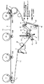
詳しく説明すると、図24に示すように、中間転写ベルト110を介して二次転写ローラ133と二次転写対向ローラ116とで形成した二次転写ニップへ用紙Sの先端が突入することにより、二次転写ニップが用紙Sの厚さ分だけ押し広げられる。二次転写ニップが用紙Sの厚さ分だけ押し広げられると二次転写対向ローラ116の駆動に突発的に負荷が加わり、二次転写対向ローラ116の回転が一時的に遅くなる。これにより、二次転写対向ローラ116で送られるベルト量よりも二次転写ニップ上流側張架面の上流端が巻き付いている駆動ローラ114から送り出されるベルト量の方が多くなる。その結果、二次転写ニップ上流側張架面が弛み気味となる。   More specifically, as shown in FIG. 24, the leading edge of the sheet S enters the secondary transfer nip formed by the secondary transfer roller 133 and the secondary transfer counter roller 116 via the intermediate transfer belt 110, thereby The next transfer nip is expanded by the thickness of the sheet S. When the secondary transfer nip is expanded by the thickness of the paper S, a load is suddenly applied to the driving of the secondary transfer counter roller 116, and the rotation of the secondary transfer counter roller 116 is temporarily delayed. As a result, the belt amount fed from the driving roller 114 around which the upstream end of the secondary transfer nip upstream stretch surface is wound is larger than the belt amount fed by the secondary transfer counter roller 116. As a result, the stretch surface on the upstream side of the secondary transfer nip becomes loose.

このように転写紙Sが二次転写ニップに対して突入することで生じる負荷変動により中間転写ベルト110が弛み張力変動が生じると、駆動ローラ114、従動ローラ115及び二次転写対向ローラ116により張架され回転移動している中間転写ベルト110に速度変動が生じる。そのため、このときに感光体ドラム104から中間転写ベルト110に一次転写部で画像の転写が行われると前記速度変動のため上述したような画質劣化が生じてしまう。   When the intermediate transfer belt 110 is slackened due to the load fluctuation caused by the transfer paper S entering the secondary transfer nip as described above, the driving roller 114, the driven roller 115, and the secondary transfer counter roller 116 stretch the tension. A speed fluctuation occurs in the intermediate transfer belt 110 that is laid and rotating. For this reason, if an image is transferred from the photosensitive drum 104 to the intermediate transfer belt 110 at the primary transfer portion at this time, the image quality deterioration as described above occurs due to the speed fluctuation.

特許文献1に記載の画像形成装置には、用紙が二次転写ニップに突入することで弛み気味となる中間転写ベルトの二次転写ニップ上流側張架面で、中間転写ベルトを内側に屈曲させるように外側からバネにより付勢するテンションローラが設けられている。中間転写ベルトの二次転写ニップ上流側張架面の張力が減少すると、バネの付勢力によってテンションローラが内側に変位し、前記二次転写ニップ上流側張架面の張力を増加させる。これにより、二次転写ニップに用紙を通紙した際に前記二次転写ニップ上流側転写面の張力が低下して前記速度変動が生じるのを抑制できるとされている。   In the image forming apparatus described in Patent Document 1, the intermediate transfer belt is bent inward on the stretched surface on the upstream side of the secondary transfer nip of the intermediate transfer belt which becomes loose when the paper enters the secondary transfer nip. Thus, a tension roller that is urged by a spring from the outside is provided. When the tension on the secondary transfer nip upstream stretch surface of the intermediate transfer belt decreases, the tension roller is displaced inward by the spring biasing force, and the tension on the secondary transfer nip upstream stretch surface is increased. Thereby, when the sheet is passed through the secondary transfer nip, it is possible to suppress the occurrence of the speed fluctuation due to the decrease in the tension of the transfer surface upstream of the secondary transfer nip.

しかしながら、特許文献1に記載の画像形成装置では、用紙の転写ニップ突入時にテンションローラが変位して前記二次転写ニップ上流側張架面の張力が強められるわけではない。すなわち、用紙が二次転写ニップに突入して、中間転写ベルトの二次転写ニップ上流側張架面の張力が低減してから、テンションローラが変位して前記二次転写ニップ上流側張架面の張力が強められる。そのため、用紙の二次転写ニップ突入直後は、前記二次転写ニップ上流側張架面が弛み気味となるので、上述したように中間転写ベルト110に速度変動が生じる。そして、このときに感光体ドラム104から中間転写ベルト110に一次転写部で画像の転写が行われると前記速度変動のため上述したような画質劣化が生じてしまう。   However, in the image forming apparatus described in Patent Document 1, the tension roller is not displaced when the sheet enters the transfer nip, and the tension on the upstream surface of the secondary transfer nip is not increased. That is, after the paper enters the secondary transfer nip and the tension on the secondary transfer nip upstream stretch surface of the intermediate transfer belt is reduced, the tension roller is displaced and the secondary transfer nip upstream stretch surface The tension of is increased. For this reason, immediately after the sheet enters the secondary transfer nip, the stretched surface on the upstream side of the secondary transfer nip becomes loose, and as described above, the intermediate transfer belt 110 fluctuates in speed. At this time, if the image is transferred from the photosensitive drum 104 to the intermediate transfer belt 110 at the primary transfer portion, the image quality deterioration as described above occurs due to the speed fluctuation.

また、特許文献1に記載される画像形成装置では、装置の小型化のために、二次転写ニップ下流側張架面で中間転写ベルトを90°以上内側に屈曲させて張架している。このため、中間転写ベルトを90°以上内側に屈曲させる箇所で局所的な応力が発生し、この局所的な応力により中間転写ベルトの耐久性が得難いという問題がある。   Further, in the image forming apparatus described in Patent Document 1, in order to reduce the size of the apparatus, the intermediate transfer belt is stretched by being bent inward by 90 ° or more on the stretching surface on the downstream side of the secondary transfer nip. For this reason, local stress is generated at a position where the intermediate transfer belt is bent inward by 90 ° or more, and there is a problem that it is difficult to obtain durability of the intermediate transfer belt due to this local stress.

また、これまでトナー像担持ベルトが中間転写ベルトである中間転写方式の画像形成装置について説明したが、高画質化のために中間転写ベルト上のトナー像を用紙へ転写する際、画像転写と画像定着とを同時におこなう転写同時定着方式の画像形成装置であっても、上記転写部で同様の問題が生じ得る。   Further, the intermediate transfer type image forming apparatus in which the toner image carrying belt is an intermediate transfer belt has been described so far. However, when transferring the toner image on the intermediate transfer belt to a sheet for image quality improvement, image transfer and image transfer are performed. The same problem may occur in the transfer section even in an image forming apparatus of a simultaneous transfer fixing system that performs fixing at the same time.

また、トナー像担持ベルトが感光体ベルトであり感光体ベルト上のトナー像を転写部で用紙に直接転写する直接転写方式の画像形成装置であっても、前記転写部で同様の問題が生じ得る。この場合は、用紙が転写部に突入する際に、それまで一定速度で駆動されていた感光体ベルトの速度変動が生じる。この感光体ベルトの速度変動により、潜像を形成する露光光の照射タイミングと感光体ベルト表面が露光位置を通過するタイミングにズレが生じ、感光体ベルト上に形成される潜像の位置ズレが生じるという不具合が発生し得る。   Further, even in a direct transfer type image forming apparatus in which the toner image carrying belt is a photosensitive belt and the toner image on the photosensitive belt is directly transferred to a sheet by the transfer portion, the same problem may occur in the transfer portion. . In this case, when the sheet enters the transfer portion, the speed fluctuation of the photosensitive belt that has been driven at a constant speed until then occurs. Due to the speed fluctuation of the photosensitive belt, a deviation occurs between the exposure light irradiation timing for forming the latent image and the timing when the surface of the photosensitive belt passes the exposure position, and the positional deviation of the latent image formed on the photosensitive belt is shifted. A malfunction that occurs may occur.

本発明は以上の問題点に鑑みなされたものであり、その目的は、転写材の転写ニップ突入時におけるベルト像担持体の速度変動を抑制できる画像形成装置を提供することである。   The present invention has been made in view of the above problems, and an object of the present invention is to provide an image forming apparatus capable of suppressing the speed fluctuation of the belt image carrier when the transfer material enters the transfer nip.

上記目的を達成するために、請求項1の発明は、複数の張架ローラによって張架されながら無端移動せしめられるループ状のベルト像担持体と、該ベルト像担持体を介して該複数の張架ローラの1つと対向し、該ベルト像担持体のループ外側面であるおもて面に当接して転写ニップを形成する転写ローラが設けられ、該転写ニップ内に挟み込んだ転写材へ該おもて面に担持した画像を転写する転写手段と、を備えた画像形成装置において、前記転写ローラの近傍で、前記ベルト像担持体の前記転写ニップよりもベルト像担持体移動方向上流側の領域に当接する当接部材と、前記当接部材と前記転写ローラとを支持し、前記転写材の転写ニップ突入時の転写ローラ変位に連動して該当接部材を前記ベルト像担持体の張力が増加する方向に変位させる連動手段とを有し、前記連動手段は、前記転写ローラを支持する転写ローラ支持部材と、前記当接部材を支持する当接部材支持部材と、各々の支持部材間の距離を規制する規制部材とで構成されることを特徴とするものである。
また、請求項の発明は、請求項の画像形成装置において、上記転写ローラ支持部材と上記当接部材支持部材との間の距離が上記規制部材によって調節可能であることを特徴とするものである。
また、請求項の発明は、請求項またはの画像形成装置において、上記記当接部材は、当接部材自身や上記当接部材支持部材にかかる重力によって、上記ベルト像担持体に対してループ内側から外側に当接することを特徴とするものである。
また、請求項の発明は、請求項1またはの画像形成装置において、上記当接部材を上記ベルト像担持体に対してループ内側から外側に当接させるように付勢する付勢手段を有することを特徴とするものである。
また、請求項の発明は、請求項1、2、3またはの画像形成装置において、上記ベルト像担持体に対する上記当接部材の位置を転写材の厚さに応じて調節することを特徴とするものである。
また、請求項の発明は、請求項の画像形成装置において、転写材の厚さを検知する転写材厚さ検知手段を備えており、前記転写材検知手段によって検知した厚さに応じて、上記ベルト像担持体に対する上記当接部材の位置を調節することを特徴とするものである。
また、請求項の発明は、請求項1、2、3、4またはの画像形成装置において、上記転写ニップ近傍に設けられ、上記ベルト像担持体または転写材を加熱する加熱手段を有し、前記転写ニップで前記ベルト像担持体上のトナー像を転写材に転写すると同時に定着するように構成したことを特徴とするものである。
In order to achieve the above object, the invention of claim 1 is directed to a loop-shaped belt image carrier that is endlessly moved while being stretched by a plurality of tension rollers, and the plurality of tension belts via the belt image carrier. A transfer roller that faces one of the gantry rollers and abuts against the front surface, which is the outer surface of the loop of the belt image carrier, to form a transfer nip, is provided to the transfer material sandwiched in the transfer nip. An image forming apparatus comprising: a transfer unit that transfers an image carried on the front surface; and an area upstream of the transfer nip of the belt image carrier in the belt image carrier moving direction in the vicinity of the transfer roller. The contact member that contacts the contact member, and the contact member and the transfer roller are supported, and the tension of the belt image carrier increases in accordance with the displacement of the transfer roller when the transfer material enters the transfer nip. Displaced in the direction Possess the interlocking means that the interlocking means regulates the transfer roller supporting member supporting the transfer roller, and the contact member supporting member supporting the contact member, the distance between each of the support member restrainer It is characterized by comprising a member .
According to a second aspect of the present invention, in the image forming apparatus according to the first aspect , a distance between the transfer roller support member and the contact member support member can be adjusted by the restriction member. It is.
According to a third aspect of the present invention, in the image forming apparatus according to the first or second aspect , the abutting member is moved against the belt image carrier by gravity applied to the abutting member itself or the abutting member supporting member. In this way, the loop abuts from the inside to the outside.
The invention of claim 4 is the image forming apparatus according to claim 1 or 2, urges for urging said contact member so as to abut against the outer loop inside against the belt image carrier It has the means.
The invention of claim 5, claim 1, in the image forming apparatus 3 or 4, adjusting the position of the contact member with respect to the belt image bearing member in accordance with the thickness of the transfer material It is characterized by.
According to a sixth aspect of the present invention, in the image forming apparatus according to the fifth aspect , the image forming apparatus further comprises a transfer material thickness detecting means for detecting the thickness of the transfer material, and the thickness is detected by the transfer material detecting means. The position of the abutting member with respect to the belt image carrier is adjusted.
The invention of claim 7 is the image forming apparatus according to claim 1, 2, 3, 4 or 5, provided in the vicinity of the transfer nip, a heating means for heating the belt image carrier or a transfer material And the toner image on the belt image carrier is transferred to the transfer material and fixed at the transfer nip at the same time.

本発明においては、転写材の転写ニップ突入時に転写ローラが変位するのに連動して、ベルト像担持体の転写ニップ上流側張架面の張力を強める方向に当接部材が変位する。これにより、転写材の転写ニップ突入直後から、前記転写ニップ上流側張架面の張力が当接部材によって強められ前記転写ニップ上流側張架面の張力低下を抑制することができる。よって、転写材の転写ニップ突入直後から、前記転写ニップ上流側張架面の張力が低下することで生じるベルト像担持体の速度変動を抑制することができる。   In the present invention, the abutting member is displaced in a direction in which the tension of the tension surface on the upstream side of the transfer nip of the belt image carrier is increased in conjunction with the displacement of the transfer roller when the transfer material enters the transfer nip. As a result, immediately after the transfer material enters the transfer nip, the tension on the upstream surface of the transfer nip is increased by the contact member, and a decrease in the tension on the upstream surface of the transfer nip can be suppressed. Therefore, it is possible to suppress the speed fluctuation of the belt image carrier that occurs due to the decrease in the tension of the tension surface on the upstream side of the transfer nip immediately after the transfer material enters the transfer nip.

以上、本発明によれば、転写材の転写ニップ突入時におけるベルト像担持体の速度変動を抑制できるという優れた効果がある。   As described above, according to the present invention, there is an excellent effect that the speed fluctuation of the belt image carrier when the transfer material enters the transfer nip can be suppressed.

本実施形態に係る画像形成装置の概略構成図。1 is a schematic configuration diagram of an image forming apparatus according to an embodiment. 従来の画像形成装置の概略構成図。1 is a schematic configuration diagram of a conventional image forming apparatus. 中転駆動ローラと従動ローラとの速度変動を示す図。The figure which shows the speed fluctuation | variation of a middle transfer drive roller and a driven roller. 位置ズレが発生したトナー像が転写された用紙の模式図。FIG. 6 is a schematic diagram of a sheet on which a toner image in which positional deviation has occurred is transferred. (a)用紙がプレニップ部に突入した際の力の伝達を示した図、(b)用紙がプレニップ部に突入した際の二次転写ニップ近傍の拡大説明図、(c)用紙がプレニップ部に突入した際の速度変動を説明するグラフ。(A) A diagram showing the transmission of force when the paper enters the pre-nip portion, (b) an enlarged explanatory view near the secondary transfer nip when the paper enters the pre-nip portion, (c) the paper enters the pre-nip portion. The graph explaining the speed fluctuation when entering. (a)用紙が本ニップ部に突入した際の力の伝達を示した図、(b)用紙が本ニップ部に突入した際の二次転写ニップ近傍の拡大図、(c)用紙が本ニップ部に突入した際の速度変動を説明するグラフ。(A) A diagram showing the transmission of force when the paper enters the main nip, (b) an enlarged view of the vicinity of the secondary transfer nip when the paper enters the main nip, and (c) the paper is in the main nip. The graph explaining the speed fluctuation | variation at the time of entering a part. 用紙の本ニップ部突入によって中転駆動ローラと入口ローラとが共に減速するメカニズムの説明図。Explanatory drawing of the mechanism in which both the intermediate transfer drive roller and the entrance roller decelerate due to the entry of the main nip portion of the paper. (a)中間転写ベルトのプレニップ領域が戻る際の力の伝達を示した図、(b)中間転写ベルトのプレニップ領域が戻る際の二次転写ニップ近傍の拡大説明図、(c)中間転写ベルトのプレニップ領域が戻ることによる速度変動を説明するグラフ。(A) The figure which showed transmission of force when the pre-nip area | region of an intermediate transfer belt returns, (b) The expansion explanatory view of the secondary transfer nip vicinity when the pre-nip area | region of an intermediate transfer belt returns, (c) Intermediate transfer belt The graph explaining the speed fluctuation | variation by returning the pre-nip area | region of. テンションローラ及び二次転写ローラの変位と、中転駆動ローラ及び従動ローラの速度変動との関係を示すグラフ。6 is a graph showing a relationship between displacement of a tension roller and a secondary transfer roller and speed fluctuations of a middle transfer driving roller and a driven roller. 従来構成の一例を示す図。The figure which shows an example of a conventional structure. 従来構成の他例を示す図。The figure which shows the other example of a conventional structure. 構成例1に係る画像形成装置の要部の概略構成図。1 is a schematic configuration diagram of a main part of an image forming apparatus according to Configuration Example 1. FIG. 構成例1に係る機構の動作の詳細図。FIG. 5 is a detailed view of the operation of the mechanism according to Configuration Example 1; 構成例2に係る画像形成装置の要部の概略構成図。FIG. 5 is a schematic configuration diagram of a main part of an image forming apparatus according to Configuration Example 2. 用紙突入時からの経過時間と従動ローラ線速変動率との関係のシミュレーション結果を示すグラフ。The graph which shows the simulation result of the relationship between the elapsed time from the time of paper rushing, and a driven roller linear velocity fluctuation rate. 構成例3に係る画像形成装置の二次転写ユニット近傍の拡大図。FIG. 10 is an enlarged view of the vicinity of a secondary transfer unit of an image forming apparatus according to Configuration Example 3. カム位置切り替え機構の制御回路図。The control circuit diagram of a cam position switching mechanism. モード切り替えのフローチャート。The flowchart of mode switching. 紙厚によって押し当てローラ支持部材への突き当て量を変化させる制御のフローチャート。The flowchart of the control which changes the amount of abutting to a pressing roller support member with paper thickness. 用紙厚さ検知を行う場合の構成図。The block diagram in the case of performing paper thickness detection. 用紙の厚さを検知してモード切替を行う場合の動作フローチャート。FIG. 6 is an operation flowchart when the mode is switched by detecting the thickness of a sheet. 構成例5に係る転写定着装置を有する画像形成装置の概略構成図。FIG. 10 is a schematic configuration diagram of an image forming apparatus having a transfer fixing device according to Configuration Example 5. 構成例5に係る他構成の転写定着装置を有する画像形成装置の概略構成図。FIG. 10 is a schematic configuration diagram of an image forming apparatus having a transfer fixing device of another configuration according to Configuration Example 5. 転写材が二次転写ニップに突入した際に中間転写ベルトの張架状態が変化した状態を示す模式図。FIG. 6 is a schematic diagram illustrating a state in which the tension state of the intermediate transfer belt is changed when the transfer material enters the secondary transfer nip.

以下、本発明を適用した画像形成装置の一実施形態について説明する。
図1は、本実施形態に係る画像形成装置の概略構成図である。この画像形成装置は、イエロー(Y)、シアン(C)、マゼンタ(M)、ブラック(Bk)のトナー像を形成するための4つのプロセスユニット100Y,100C,100M,100Bkを備えている。また、機内で記録シートを搬送するための複数のガイド板からなる用紙搬送路、レジストローラ対9、定着装置15、光書込ユニット(不図示)、及び、転写ユニット50なども備えている。
Hereinafter, an embodiment of an image forming apparatus to which the present invention is applied will be described.
FIG. 1 is a schematic configuration diagram of an image forming apparatus according to the present embodiment. The image forming apparatus includes four process units 100Y, 100C, 100M, and 100Bk for forming yellow (Y), cyan (C), magenta (M), and black (Bk) toner images. Further, a sheet conveyance path composed of a plurality of guide plates for conveying the recording sheet in the apparatus, a registration roller pair 9, a fixing device 15, an optical writing unit (not shown), a transfer unit 50, and the like are also provided.

本実施形態の画像形成装置は、4つのプロセスユニット100Y,100C,100M,100Bkを、後述する中間転写ベルト2に対してその無端移動方向に沿って並べた所謂タンデム型の構成になっている。   The image forming apparatus according to the present embodiment has a so-called tandem configuration in which four process units 100Y, 100C, 100M, and 100Bk are arranged along an endless moving direction with respect to an intermediate transfer belt 2 described later.

各色のプロセスユニット100Y,100C,100M,100Bkは、それぞれ、潜像担持体たる感光体ドラム1Y,1C,1M,1Bkと、その周囲に配設される各種装置とを1つのユニットとして共通の支持体に支持するものであり、プリンタ部本体に対して着脱可能になっている。そして、互いに使用するトナーの色が異なる点以外は同様の構成になっている。   The process units 100Y, 100C, 100M, and 100Bk for the respective colors share a common support as a unit with the photosensitive drums 1Y, 1C, 1M, and 1Bk as latent image carriers and various devices disposed around the photosensitive drums 1Y, 1C, 1M, and 1Bk. It is supported by the body and is detachable from the printer unit main body. The configuration is the same except that the colors of the toners used are different.

Y用のプロセスユニット100Yを例にすると、トナー像担持体たる感光体ドラム1Yの周囲に、帯電装置103Y、現像装置101Y、ドラムクリーニング装置102Y等を有している。プロセスユニット100Yの感光体ドラム1Yは、図示しない駆動手段によって図中反時計回り方向に回転駆動せしめる。帯電装置103Yは、回転駆動される感光体ドラム1Yの周面をトナーの帯電極性と同極性に一様帯電せしめる。図示しない光書込ユニットは、画像情報に基づいて、レーザーダイオードを駆動して、回転中の帯電した感光体ドラム1Yに対して、レーザー光をそれぞれ回転軸線方向に偏向せしめながら照射することで、光走査処理をおこなう。これにより、感光体ドラム1Yには、Y画像情報に基づいた静電潜像が形成される。感光体ドラム1Yとしては、アルミニウム等の素管に、感光性を有する有機感光材の塗布による感光層を形成したドラム状のものを用いている。但し、無端ベルト状のものを用いても良い。   Taking the Y process unit 100Y as an example, a charging device 103Y, a developing device 101Y, a drum cleaning device 102Y, and the like are provided around a photosensitive drum 1Y as a toner image carrier. The photosensitive drum 1Y of the process unit 100Y is driven to rotate counterclockwise in the drawing by a driving unit (not shown). The charging device 103Y uniformly charges the peripheral surface of the rotationally driven photosensitive drum 1Y to the same polarity as the charging polarity of the toner. An optical writing unit (not shown) drives a laser diode based on image information, and irradiates the rotating charged photosensitive drum 1Y while deflecting the laser light in the direction of the rotation axis, respectively. Perform optical scanning processing. Thereby, an electrostatic latent image based on the Y image information is formed on the photosensitive drum 1Y. As the photosensitive drum 1Y, a drum-like member is used in which a photosensitive layer is formed by applying a photosensitive organic photosensitive material on a base tube made of aluminum or the like. However, an endless belt may be used.

現像装置101Yは、図示しない磁性キャリアと非磁性のYトナーとを含有する二成分現像剤(以下、単に現像剤という)を用いて、感光体ドラム1Y上の静電潜像を現像する。二成分現像剤の代わりに、磁性キャリアを含まない一成分現像剤によって現像をおこなうタイプのものを使用していもよい。   The developing device 101Y develops the electrostatic latent image on the photosensitive drum 1Y using a two-component developer (hereinafter simply referred to as a developer) containing a magnetic carrier (not shown) and non-magnetic Y toner. Instead of the two-component developer, a type that develops with a one-component developer not containing a magnetic carrier may be used.

現像によって感光体ドラム1Y上に形成されたYトナー像は、後述するY用の一次転写ニップで中間転写ベルト2のおもて面に転写される。このようにしてYトナー像を転写した後の感光体ドラム1Y上に付着している転写残トナーは、ドラムクリーニング装置102Yによって感光体ドラム1Y表面から除去される。このクリーニングに先立って、感光体ドラム1Yの表面は図示しない除電ランプによる光照射を受けて除電される。   The Y toner image formed on the photosensitive drum 1Y by development is transferred to the front surface of the intermediate transfer belt 2 at a Y primary transfer nip described later. The transfer residual toner adhering to the photosensitive drum 1Y after the Y toner image is transferred in this way is removed from the surface of the photosensitive drum 1Y by the drum cleaning device 102Y. Prior to this cleaning, the surface of the photosensitive drum 1Y is discharged by receiving light from a discharge lamp (not shown).

Y用のプロセスユニット100Yについて説明したが、M,C,Bk用のプロセスユニットにおいても、同様にして感光体ドラム1M,1C,1Bkの表面にM,C,Bkトナー像が形成される。   Although the Y process unit 100Y has been described, M, C, and Bk toner images are similarly formed on the surfaces of the photosensitive drums 1M, 1C, and 1Bk in the M, C, and Bk process units.

4つのプロセスユニット100Y,100C,100M,100Bkの下方には、転写ユニット50が配設されている。この転写ユニット50は、トナー像担持ベルトたる中間転写ベルト2を有している。中間転写ベルト2は、中転駆動ローラ3、二次転写対向ローラ5、テンションローラ6、従動ローラ7、入口ローラ4などの張架ローラによって張架されている。この中間転写ベルト2を、感光体ドラム1Y,1C,1M,1Bkに当接させながら、中転駆動ローラ3の回転駆動によって図中時計回り方向に無端移動させる。これにより、感光体ドラム1Y,1C,1M,1Bkと中間転写ベルト2とが当接するY,C,M,Bk用の一次転写ニップが形成されている。   A transfer unit 50 is disposed below the four process units 100Y, 100C, 100M, and 100Bk. The transfer unit 50 has an intermediate transfer belt 2 as a toner image carrying belt. The intermediate transfer belt 2 is stretched by stretching rollers such as a medium transfer driving roller 3, a secondary transfer counter roller 5, a tension roller 6, a driven roller 7, and an entrance roller 4. The intermediate transfer belt 2 is endlessly moved in the clockwise direction in the figure by the rotational drive of the intermediate transfer driving roller 3 while being in contact with the photosensitive drums 1Y, 1C, 1M, and 1Bk. As a result, primary transfer nips for Y, C, M, and Bk where the photosensitive drums 1Y, 1C, 1M, and 1Bk and the intermediate transfer belt 2 are in contact with each other are formed.

Y,C,M,Bk用の一次転写ニップの近傍では、ベルトループ内側に配設された一次転写ローラ54Y,54C,54M,54Bkによって中間転写ベルト2を感光体ドラム1Y,1C,1M,1Bkに向けて押圧している。これら一次転写ローラ54Y,54C,54M,54Bkには、それぞれ図示しない電源によって一次転写バイアスが印加されている。これにより、Y,C,M,Bk用の一次転写ニップには、感光体ドラム1Y,1C,1M,1Bk上のトナー像を中間転写ベルト2に向けて静電移動させる一次転写電界が形成されている。   In the vicinity of the primary transfer nips for Y, C, M, and Bk, the intermediate transfer belt 2 is moved to the photosensitive drums 1Y, 1C, 1M, and 1Bk by primary transfer rollers 54Y, 54C, 54M, and 54Bk disposed inside the belt loop. It is pushing toward. A primary transfer bias is applied to the primary transfer rollers 54Y, 54C, 54M, and 54Bk by a power source (not shown). As a result, a primary transfer electric field for electrostatically moving the toner images on the photosensitive drums 1Y, 1C, 1M, and 1Bk toward the intermediate transfer belt 2 is formed in the primary transfer nips for Y, C, M, and Bk. ing.

図中時計回り方向の無端移動に伴ってY,C,M,Bk用の一次転写ニップを順次通過していく中間転写ベルト2のおもて面には、各一次転写ニップでトナー像が順次重ね合わせて一次転写される。この重ね合わせの一次転写により、中間転写ベルト2のおもて面には4色重ね合わせトナー像(以下、4色トナー像という)が形成される。   In the drawing, toner images are sequentially formed at the primary transfer nips on the front surface of the intermediate transfer belt 2 that sequentially passes through the primary transfer nips for Y, C, M, and Bk with endless movement in the clockwise direction. Overlaid and primary transferred. By this primary transfer of superposition, a four-color superposed toner image (hereinafter referred to as a four-color toner image) is formed on the front surface of the intermediate transfer belt 2.

中間転写ベルト2の図中下方には、当接部材たる二次転写ローラ8が配設されており、中間転写ベルト2における二次転写対向ローラ5に対する掛け回し箇所にベルトおもて面から当接して二次転写ニップを形成している。これにより、中間転写ベルト2のおもて面と、二次転写ローラ8とが当接する二次転写ニップが形成されている。二次転写ローラ8の軸中心は、二次転写対向ローラ5の軸中心よりも、用紙搬送方向上流側に位置している。本実施形態においては、二次転写ローラ8を不図示のモータにより図中反時計回りに回転駆動させている。なお、二次転写ローラ8が中間転写ベルト2に対して連れ回る構成でもよい。   A secondary transfer roller 8 serving as an abutting member is disposed below the intermediate transfer belt 2 in the drawing, and a portion of the intermediate transfer belt 2 that is wound around the secondary transfer counter roller 5 is contacted from the belt front surface. A secondary transfer nip is formed in contact therewith. Thus, a secondary transfer nip is formed in which the front surface of the intermediate transfer belt 2 and the secondary transfer roller 8 are in contact with each other. The shaft center of the secondary transfer roller 8 is located upstream of the shaft center of the secondary transfer counter roller 5 in the paper transport direction. In this embodiment, the secondary transfer roller 8 is driven to rotate counterclockwise in the figure by a motor (not shown). Note that the secondary transfer roller 8 may be rotated around the intermediate transfer belt 2.

ベルトループ内の二次転写対向ローラ5には、図示しない電源によってトナーと同極性の二次転写バイアスが印加されている。一方、ベルトループ外の二次転写ローラ8は接地されている。これにより、二次転写ニップ内に二次転写電界が形成されている。   A secondary transfer bias having the same polarity as the toner is applied to the secondary transfer counter roller 5 in the belt loop by a power source (not shown). On the other hand, the secondary transfer roller 8 outside the belt loop is grounded. Thereby, a secondary transfer electric field is formed in the secondary transfer nip.

二次転写ニップの図中右側方には、レジストローラ対9が配設されている。画像形成に並行して、給紙ローラ18を回転し、給紙カセット20から転写材たる用紙19を繰り出し、分離ローラ17で1枚ずつ分離して用紙搬送経路に入れ、搬送ローラ16で搬送してレジストローラ対9に突き当てて止める。または、手差し部上の用紙を繰り出し、用紙搬送経路に入れ、同じくレジストローラ対9に突き当てて止める。   A registration roller pair 9 is disposed on the right side of the secondary transfer nip in the drawing. In parallel with the image formation, the paper feed roller 18 is rotated to feed out the paper 19 as a transfer material from the paper feed cassette 20, separated one by one by the separation roller 17, put into the paper transport path, and transported by the transport roller 16. Then it stops against the registration roller pair 9. Alternatively, the paper on the manual feed portion is fed out, put into the paper conveyance path, and abutted against the registration roller pair 9 and stopped.

レジストローラ間に挟み込んだ用紙19を中間転写ベルト2上の4色トナー像に同期させ得るタイミングで二次転写ニップに送り出す。二次転写ニップ内では、中間転写ベルト2上の4色トナー像が二次転写電界やニップ圧の影響によって転写材たる用紙に一括二次転写され、用紙の白色と相まってフルカラー画像となる。   The sheet 19 sandwiched between the registration rollers is sent to the secondary transfer nip at a timing that can be synchronized with the four-color toner image on the intermediate transfer belt 2. In the secondary transfer nip, the four-color toner images on the intermediate transfer belt 2 are collectively transferred to a sheet as a transfer material by the influence of the secondary transfer electric field and the nip pressure, and a full color image is formed in combination with the white color of the sheet.

二次転写ニップを通過した中間転写ベルト2のおもて面には、二次転写ニップで用紙に転写されなかった転写残トナーが付着している。この転写残トナーは、中間転写ベルト2に当接する不図示のベルトクリーニング装置によってクリーニングされる。   On the front surface of the intermediate transfer belt 2 that has passed through the secondary transfer nip, untransferred toner that has not been transferred to the paper at the secondary transfer nip adheres. This untransferred toner is cleaned by a belt cleaning device (not shown) that contacts the intermediate transfer belt 2.

二次転写ニップを通過した用紙19は、中間転写ベルト2と搬送ベルト11との搬送力により定着装置15に向けて送られる。定着装置15は、定着ローラ13と加熱ローラ14とで張架された定着ベルト13aに対して加圧ローラ12を圧接して構成する。定着ベルト13aは加熱ローラ14内の図示しないIHコイルによって加熱され、画像定着に必要な温度まで加熱される。一方、加圧ローラ12にも内部に図示しないヒーターを内蔵しており、待機時の予備加熱に使用している。用紙上の未定着画像は、定着ベルト13aと加圧ローラ12とのニップ部において熱と圧力を与えられ、用紙19に定着される。なお、定着装置15のヒーターはIHコイルを用いたものでなくてもよく、熱ローラ対で構成された方式であっても良い。   The sheet 19 that has passed through the secondary transfer nip is fed toward the fixing device 15 by the conveyance force between the intermediate transfer belt 2 and the conveyance belt 11. The fixing device 15 is configured by pressing the pressure roller 12 against a fixing belt 13 a stretched between a fixing roller 13 and a heating roller 14. The fixing belt 13a is heated by an IH coil (not shown) in the heating roller 14, and is heated to a temperature necessary for image fixing. On the other hand, the pressure roller 12 also incorporates a heater (not shown) and is used for preheating during standby. The unfixed image on the paper is fixed on the paper 19 by applying heat and pressure at the nip portion between the fixing belt 13 a and the pressure roller 12. The heater of the fixing device 15 does not have to use an IH coil, and may be a system constituted by a pair of heat rollers.

定着装置15で熱と圧力とを加えて転写画像を定着して後、図示しない排紙トレイに排出される。または、図示しない両面反転機構により再び転写位置へと導き、裏面にも画像を記録、定着して後、排紙トレイに排出する。   The fixing device 15 applies heat and pressure to fix the transferred image, and then the paper is discharged to a paper discharge tray (not shown). Alternatively, the image is again guided to the transfer position by a double-side reversing mechanism (not shown), and an image is recorded and fixed on the back surface, and then discharged to a paper discharge tray.

中間転写ベルト2に当接して二次転写ニップを形成している二次転写ローラ8は、金属製の芯金とこれの周面に被覆されたゴム等の弾性部材とを具備している。二次転写ニップでは、中間転写ベルト2における二次転写対向ローラ5に対する掛け回し箇所が、二次転写ローラ8の表面の弾性部材に食い込んでいる。これにより、幅広い二次転写ニップが形成されている。   The secondary transfer roller 8 that is in contact with the intermediate transfer belt 2 to form a secondary transfer nip includes a metal cored bar and an elastic member such as rubber coated on the peripheral surface thereof. In the secondary transfer nip, the portion of the intermediate transfer belt 2 that is wound around the secondary transfer counter roller 5 bites into the elastic member on the surface of the secondary transfer roller 8. Thereby, a wide secondary transfer nip is formed.

次に、従来の画像形成装置の中間転写ベルト2の課題について説明する。図2は従来の画像形成装置の概略構成図であり、基本的な構成は本実施形態の画像形成装置と略同じなので、その説明は省略する。   Next, problems of the intermediate transfer belt 2 of the conventional image forming apparatus will be described. FIG. 2 is a schematic configuration diagram of a conventional image forming apparatus, and the basic configuration is substantially the same as that of the image forming apparatus of the present embodiment, and thus description thereof is omitted.

用紙19が二次転写ニップ部に突入する際、中間転写ベルト2の感光体ドラム1Y,1C,1M,1Bkに当接する領域(以下、一次転写領域という)を張架する中転駆動ローラ3や従動ローラ7には図3に示すような速度変動が発生する。このような現象は特に厚紙通紙時(ここでは連量220[kg]紙、坪量256[g/m]紙以上を想定している)により顕著に見られる現象である。 When the sheet 19 enters the secondary transfer nip portion, the intermediate transfer driving roller 3 that stretches a region (hereinafter referred to as a primary transfer region) that contacts the photosensitive drums 1Y, 1C, 1M, and 1Bk of the intermediate transfer belt 2 The driven roller 7 undergoes speed fluctuation as shown in FIG. Such a phenomenon is particularly noticeable when a thick paper is passed (in this example, a continuous weight of 220 [kg] paper, a basis weight of 256 [g / m 2 ] paper or more is assumed).

それに対して、感光体ドラム1Y,1C,1M,1Bkは用紙先端が二次転写ニップ突入時においてもほぼ同速で回転駆動されるので、感光体ドラム1Y,1C,1M,1Bkと中間転写ベルト2との間で速度差が発生する。この速度差によって、一次転写ニップにおいて転写位置ずれが発生する。   On the other hand, the photosensitive drums 1Y, 1C, 1M, and 1Bk are rotationally driven at substantially the same speed even when the leading edge of the sheet enters the secondary transfer nip, so that the photosensitive drums 1Y, 1C, 1M, and 1Bk and the intermediate transfer belt are driven. A speed difference occurs between the two. Due to this speed difference, a transfer position shift occurs in the primary transfer nip.

図4は、単色の画像形成を行った場合に、前述したような転写位置ずれが発生したトナー象が最終画像として転写された用紙19を模式的に示す説明図である。   FIG. 4 is an explanatory diagram schematically showing a sheet 19 on which a toner image having a transfer position shift as described above is transferred as a final image when a single color image is formed.

用紙先端の二次転写ニップ突入時に発生した一次転写ニップにおける転写位置ずれを含むトナー像は、一次転写ニップから二次転写ニップまでの距離をLとすると、用紙先端からLの位置で用紙19に転写または転写・定着される。このため、排紙される用紙19上の最終画像には、図4に示すように用紙先端からLの位置に正常な画像の部分I1よりも色が薄い部分I2や色が濃い部分I3という局所的な濃度ムラをもった画像となる。   A toner image including a transfer position shift in the primary transfer nip that occurs when the leading edge of the sheet enters the secondary transfer nip is defined on the sheet 19 at a position L from the leading edge of the sheet, where L is the distance from the primary transfer nip to the secondary transfer nip. Transfer or transfer / fixing. For this reason, as shown in FIG. 4, the final image on the paper 19 to be ejected is a local area I2 that is lighter in color than the normal image portion I1 or a portion I3 that is darker than the normal image portion I1. The image has a typical density unevenness.

なお、複数色の画像形成を行った場合は、各色で一次転写ニップから二次転写ニップまでの距離が異なるため、各色で用紙先端から濃度ムラまでの距離Lが異なる画像なって出力される。   Note that, when images of a plurality of colors are formed, the distances from the primary transfer nip to the secondary transfer nip are different for each color, so that images having different distances L from the leading edge of the paper to the density unevenness are output for each color.

このように、用紙先端の二次転写ニップ突入時に発生する一次転写ニップにおける転写位置ずれを防ぐには、用紙先端の二次転写ニップ突入時における中転駆動ローラ3や従動ローラ7の速度変動を抑制する必要がある。この中転駆動ローラ3や従動ローラ7の速度変動がどのようなメカニズムで発生するのかについて以下に述べる。   Thus, in order to prevent the transfer position shift in the primary transfer nip that occurs when the secondary transfer nip enters the leading edge of the paper, the speed fluctuations of the intermediate transfer driving roller 3 and the driven roller 7 when the secondary transfer nip enters the leading edge of the paper. It is necessary to suppress it. The mechanism by which the speed fluctuations of the intermediate transfer driving roller 3 and the driven roller 7 occur will be described below.

本実施形態の画像形成装置では、図1に示すように二次転写ローラ8の軸中心が二次転写対向ローラ5の軸中心よりも用紙搬送方向上流側に位置している。このため、中間転写ベルト2の外周面が二次転写ローラ8と当接するニップは、次の2つのニップ部を有する。すなわち、中間転写ベルト2の内周面が二次転写対向ローラ5と接触している二次転写ニップ(以下、本ニップ部という)と、二次転写ニップよりも用紙搬送方向上流側にあり、中間転写ベルト2の内周面が二次転写対向ローラ5と接触していないニップ部(以下、プレニップ部という)とを有している。   In the image forming apparatus according to the present embodiment, as shown in FIG. 1, the axial center of the secondary transfer roller 8 is located upstream of the axial center of the secondary transfer counter roller 5 in the sheet conveyance direction. For this reason, the nip where the outer peripheral surface of the intermediate transfer belt 2 contacts the secondary transfer roller 8 has the following two nip portions. That is, the inner peripheral surface of the intermediate transfer belt 2 is in a secondary transfer nip (hereinafter referred to as a main nip portion) that is in contact with the secondary transfer counter roller 5 and upstream of the secondary transfer nip in the sheet conveying direction. The inner peripheral surface of the intermediate transfer belt 2 has a nip portion that is not in contact with the secondary transfer counter roller 5 (hereinafter referred to as a pre-nip portion).

このように、本実施形態の画像形成装置では、本ニップ部やプレニップ部を有する構成であるため、中転駆動ローラ3や従動ローラ7の速度変動は、大きく分けて以下の3つの変動から成り立っている。   As described above, since the image forming apparatus of the present embodiment has the main nip portion and the pre-nip portion, the speed fluctuations of the intermediate transfer driving roller 3 and the driven roller 7 are roughly divided into the following three fluctuations. ing.

<(1)用紙19の先端がプレニップ部に突入することによる速度変動>
図5は、用紙19の先端がプレニップ部に突入した際に生じる速度変動の説明図である。用紙先端がプレニップ部に突入すると、中間転写ベルト2の転写ニップ上流側張架面である二次転写対向ローラ5と入口ローラ4との張架領域(以下、プレニップ領域T3という)が内側に押される。中間転写ベルト2のプレニップ領域T3が内側に押されると、プレニップ領域T3の用紙先端との当接部より中間転写ベルト移動方向上流側の部分が、図5(b)に示すように、中間転写ベルト移動方向へ引っ張られる。その結果、図5(b)に示すように、入口ローラ4には中間転写ベルト移動方向と同方向に引っ張る力I2が働き、入口ローラ4に回転方向と同方向のトルクE2が働く。その結果、入口ローラ4が加速する。
<(1) Speed fluctuation due to the leading edge of the paper 19 entering the prenip>
FIG. 5 is an explanatory diagram of speed fluctuation that occurs when the leading edge of the paper 19 enters the pre-nip portion. When the leading edge of the sheet enters the pre-nip portion, a stretch region (hereinafter referred to as pre-nip region T3) between the secondary transfer counter roller 5 and the entrance roller 4 which is a stretch surface on the upstream side of the transfer nip of the intermediate transfer belt 2 is pushed inward. It is. When the pre-nip region T3 of the intermediate transfer belt 2 is pushed inward, the portion of the pre-nip region T3 on the upstream side in the moving direction of the intermediate transfer belt from the contact portion with the front end of the sheet is intermediate transfer as shown in FIG. Pulled in the belt moving direction. As a result, as shown in FIG. 5B, the inlet roller 4 is subjected to a pulling force I2 in the same direction as the intermediate transfer belt moving direction, and the inlet roller 4 is subjected to a torque E2 in the same direction as the rotational direction. As a result, the entrance roller 4 is accelerated.

また、図5(a)の矢印F(2)に示すように、中間転写ベルト移動方向と同方向に引っ張る力I2は、中間転写ベルト2を介して中転駆動ローラ3に伝達され、中転駆動ローラ3に回転方向と同方向のトルクがかかり、図5(c)で太線で示すように中転駆動ローラ3が加速される。そして、最終的には、図5(a)の矢印F(2)に示すように、中間転写ベルト移動方向と同方向に引っ張る力I2が中間転写ベルト2を介して従動ローラ7にまで伝達される。その結果、図5(c)の太線で示すように従動ローラ7が加速される。   Further, as indicated by an arrow F (2) in FIG. 5A, the force I2 pulling in the same direction as the moving direction of the intermediate transfer belt is transmitted to the intermediate transfer driving roller 3 via the intermediate transfer belt 2, and the intermediate transfer belt 3 is rotated. Torque in the same direction as the rotation direction is applied to the drive roller 3, and the intermediate transfer drive roller 3 is accelerated as shown by a thick line in FIG. Finally, as shown by an arrow F (2) in FIG. 5A, a force I2 pulling in the same direction as the intermediate transfer belt moving direction is transmitted to the driven roller 7 via the intermediate transfer belt 2. The As a result, the driven roller 7 is accelerated as indicated by the thick line in FIG.

また、中間転写ベルト2のプレニップ領域T3の用紙先端との当接部より中間転写ベルト移動方向下流側の部分が、中間転写ベルト移動方向とは逆方向へ引っ張られる。その結果、図5(b)に示すように、二次転写対向ローラ5には、中間転写ベルト移動方向とは逆方向に引っ張る力I1が働き、二次転写対向ローラ5には回転方向とは逆方向のトルクE1がかかる。これにより、二次転写対向ローラ5が減速する。   Further, a portion of the pre-nip region T3 of the intermediate transfer belt 2 on the downstream side in the intermediate transfer belt moving direction is pulled in the direction opposite to the intermediate transfer belt moving direction. As a result, as shown in FIG. 5B, the secondary transfer counter roller 5 is subjected to a pulling force I1 in the direction opposite to the intermediate transfer belt moving direction, and the secondary transfer counter roller 5 has a rotational direction. A reverse torque E1 is applied. Thereby, the secondary transfer counter roller 5 is decelerated.

また、中間転写ベルト移動方向とは逆方向へ引っ張る力I1は、図5(a)の矢印F(1)に示すように、中間転写ベルト2を介してテンションローラ6や従動ローラ7へ伝達される。伝達経路を考えれば、中間転写ベルト移動方向と同方向へ引っ張る力I2が従動ローラ7へ伝達され従動ローラ7が加速する前に、中間転写ベルト移動方向とは逆方向へ引っ張る力I1により従動ローラ7が減速するはずである。しかしながら、図5(c)を見てみると、中間転写ベルト移動方向とは逆方向へ引っ張る力I1による従動ローラ7の減速が生じていない。これは、本実施形態では、二次転写ローラ8を中転駆動ローラ3とは別のモータで駆動させたため、二次転写ローラ8の回転駆動力によって中間転写ベルト移動方向とは逆方向へ引っ張る力I1を消滅させてしまったためと考えられる。   Further, the force I1 pulling in the direction opposite to the moving direction of the intermediate transfer belt is transmitted to the tension roller 6 and the driven roller 7 via the intermediate transfer belt 2 as indicated by an arrow F (1) in FIG. The Considering the transmission path, the force I2 pulling in the same direction as the intermediate transfer belt moving direction is transmitted to the driven roller 7 and the driven roller 7 is accelerated before the driven roller 7 is accelerated by the force I1 pulling in the direction opposite to the intermediate transfer belt moving direction. 7 should slow down. However, looking at FIG. 5C, the driven roller 7 is not decelerated by the force I1 pulling in the direction opposite to the moving direction of the intermediate transfer belt. In this embodiment, since the secondary transfer roller 8 is driven by a motor different from the intermediate transfer roller 3, the secondary transfer roller 8 is pulled in the direction opposite to the moving direction of the intermediate transfer belt by the rotational driving force of the secondary transfer roller 8. This is probably because the force I1 has disappeared.

図5(b)に示すように、中転駆動ローラ3が中間転写ベルト移動方向に引っ張られる力I2により加速することで、中間転写ベルト2の一次転写領域T1が加速される。その結果、図4に示すように正常な画像の部分I1よりも色が薄い部分I2が生じるのである。   As shown in FIG. 5B, the intermediate transfer driving roller 3 is accelerated by the force I2 pulled in the intermediate transfer belt moving direction, whereby the primary transfer region T1 of the intermediate transfer belt 2 is accelerated. As a result, as shown in FIG. 4, a portion I2 having a lighter color than the portion I1 of the normal image is generated.

<(2)用紙19の先端が本ニップ部に突入することによる速度変動>
図6は、用紙先端が二次転写ニップたる本ニップ部に突入した際に生じる速度変動の説明図である。
<(2) Speed fluctuation caused by the leading edge of the paper 19 entering the nip portion>
FIG. 6 is an explanatory diagram of speed fluctuations that occur when the leading edge of the sheet enters the main nip portion that is the secondary transfer nip.

用紙19の先端が本ニップ部に突入することによる速度変動は、用紙19の先端が本ニップ部に突入する際に用紙19の先端が二次転写ローラ8を押し下げることによって二次転写対向ローラ5が減速する減少である。   The speed fluctuation due to the leading edge of the sheet 19 entering the main nip portion is caused by the secondary transfer counter roller 5 being pushed by the leading edge of the sheet 19 pushing down the secondary transfer roller 8 when the leading edge of the sheet 19 enters the main nip portion. Is a decrease that decelerates.

ここで、二次転写対向ローラ5が減速するメカニズムについて図7を用いて説明する。図7に示すように、用紙19の先端が本ニップ部に突入するためには、用紙19の先端が、二次転写ローラ8を用紙19の厚さ相当分押し下げる必要がある。   Here, the mechanism by which the secondary transfer counter roller 5 decelerates will be described with reference to FIG. As shown in FIG. 7, in order for the leading end of the sheet 19 to enter the main nip portion, the leading end of the sheet 19 needs to push down the secondary transfer roller 8 by an amount corresponding to the thickness of the sheet 19.

図7に示すように二次転写ローラ8は、付勢コイルバネ10bにより図中矢印A方向に付勢されている。二次転写ローラ8を押し下げるには、用紙19の先端が二次転写ローラ8を押し下げる力(図中の矢印B)が、付勢コイルバネ10bの付勢力を上回る必要がある。用紙19の先端の押し下げる力Bは、用紙先端を図中右側へ搬送する搬送力であり、その搬送力は二次転写対向ローラ5の回転駆動力Cである。すなわち、用紙19の先端が二次転写ローラ8に当接したとき二次転写対向ローラ5には、中間転写ベルト2を搬送するためのトルクの他に、用紙先端が二次転写ローラ8を押し下げるのに必要なトルクが生じる。その結果、図6(b)に示すように二次転写対向ローラ5の回転負荷(図中矢印D1)が増加し、二次転写対向ローラ5が減速する。   As shown in FIG. 7, the secondary transfer roller 8 is urged in the direction of arrow A in the figure by the urging coil spring 10b. In order to push down the secondary transfer roller 8, the force (arrow B in the figure) that the leading edge of the paper 19 pushes down the secondary transfer roller 8 needs to exceed the urging force of the urging coil spring 10b. The force B that pushes down the leading edge of the sheet 19 is a conveying force that conveys the leading edge of the sheet to the right side in the figure, and the conveying force is the rotational driving force C of the secondary transfer counter roller 5. That is, when the leading edge of the sheet 19 comes into contact with the secondary transfer roller 8, the leading edge of the sheet pushes down the secondary transfer roller 8 to the secondary transfer counter roller 5 in addition to the torque for transporting the intermediate transfer belt 2. The torque required for this is generated. As a result, as shown in FIG. 6B, the rotational load (arrow D1 in the figure) of the secondary transfer counter roller 5 increases, and the secondary transfer counter roller 5 decelerates.

一方、入口ローラ4についても、二次転写対向ローラ5と同様に減速が生じる。これは、用紙19の先端が本ニップ部に突入すると、用紙19の先端が二次転写ローラ8を押し下げるまで用紙19が前に進まないので、中間転写ベルト2と用紙間の摩擦力によるベルト走行負荷J2が生じる。このベルト走行負荷J2により入口ローラ4に回転方向とは逆方向のトルクD2が働き、入口ローラ4も同様に減速する。   On the other hand, the entrance roller 4 is also decelerated similarly to the secondary transfer counter roller 5. This is because when the leading edge of the sheet 19 enters the main nip portion, the sheet 19 does not advance until the leading edge of the sheet 19 pushes down the secondary transfer roller 8, so that the belt travels due to the frictional force between the intermediate transfer belt 2 and the sheet. A load J2 is generated. The belt running load J2 causes a torque D2 in the direction opposite to the rotation direction to act on the entrance roller 4, and the entrance roller 4 is similarly decelerated.

このベルト走行負荷J2は、図6(a)の矢印(3)に示すように、中間転写ベルト2を介して中転駆動ローラ3へ伝達される。なお、中転駆動ローラ3に伝達されたベルト走行負荷は、中転駆動ローラ3を回転駆動させるモータの駆動力により打ち消されるため、中転駆動ローラ3より中間転写ベルト移動方向上流側の従動ローラ7に伝達されない。   The belt running load J2 is transmitted to the intermediate transfer driving roller 3 through the intermediate transfer belt 2 as shown by an arrow (3) in FIG. The belt traveling load transmitted to the intermediate transfer driving roller 3 is canceled out by the driving force of the motor that rotationally drives the intermediate transfer driving roller 3, so that the driven roller upstream of the intermediate transfer driving roller 3 in the intermediate transfer belt moving direction. 7 is not transmitted.

二次転写対向ローラ5が減速すると、中間転写ベルト2の転写ニップ下流側張架面たる二次転写対向ローラ5と従動ローラ7との張架領域(以下、テンション制御領域T2という)が中間転写ベルト移動方向とは逆方向へ引っ張られ、図6(a)の矢印F(4)に示すように、テンションローラ6や従動ローラ7に中間転写ベルト移動方向とは逆方向の力J1が伝達される。   When the secondary transfer counter roller 5 decelerates, a stretch region (hereinafter referred to as a tension control region T2) between the secondary transfer counter roller 5 and the driven roller 7 which is a stretch surface on the downstream side of the transfer nip of the intermediate transfer belt 2 is intermediate transfer. Pulled in the direction opposite to the belt moving direction, and a force J1 in the direction opposite to the intermediate transfer belt moving direction is transmitted to the tension roller 6 and the driven roller 7 as shown by an arrow F (4) in FIG. The

従動ローラ7に中間転写ベルト移動方向とは逆方向へ引っ張る力J1が伝達されると、図6(c)の太線に示すように従動ローラ7が減速する。従動ローラ7が減速することにより、中間転写ベルト2の一次転写領域T1が中間転写ベルト移動方向とは逆方向へ引っ張られ、中転駆動ローラ3に回転方向とは逆方向のトルクがかかる。その結果、図6(c)の太線に示すように中転駆動ローラ3が減速する。   When the force J1 pulling in the direction opposite to the direction of movement of the intermediate transfer belt is transmitted to the driven roller 7, the driven roller 7 is decelerated as shown by the bold line in FIG. As the driven roller 7 decelerates, the primary transfer region T1 of the intermediate transfer belt 2 is pulled in the direction opposite to the direction of movement of the intermediate transfer belt, and torque in the direction opposite to the rotation direction is applied to the intermediate transfer drive roller 3. As a result, the intermediate transfer driving roller 3 is decelerated as indicated by the thick line in FIG.

このように、従動ローラ7や中転駆動ローラ3が減速する結果、中間転写ベルト2の一次転写領域T1が減速し、図4に示すように正常な画像の部分I1よりも色が濃い部分I3が生じるのである。   As described above, the driven roller 7 and the intermediate transfer driving roller 3 are decelerated. As a result, the primary transfer region T1 of the intermediate transfer belt 2 is decelerated, and the portion I3 that is darker than the normal image portion I1 as shown in FIG. Will occur.

<(3)用紙先端が本ニップ部に突入した後における中間転写ベルト2のプレニップ領域T3の戻りによる速度変動>
図8は、用紙先端が本ニップ部に突入した後における中間転写ベルト2のプレニップ領域T3の戻りによる変動の説明図である。
<(3) Speed fluctuation due to return of the pre-nip region T3 of the intermediate transfer belt 2 after the leading edge of the sheet has entered the nip portion>
FIG. 8 is an explanatory diagram of fluctuation due to the return of the pre-nip region T3 of the intermediate transfer belt 2 after the leading edge of the sheet has entered the main nip portion.

図8(b)に示すように、用紙先端が二次転写ローラ8を押し下げて本ニップ部へ突入すると、これまで用紙19の先端によって内側に押し込まれていた中間転写ベルト2のプレニップ領域T3が元に戻る。その結果、上記<(1)用紙19の先端がプレニップ部に突入することによる速度変動>とは逆の現象が発生する。   As shown in FIG. 8B, when the leading edge of the sheet pushes down the secondary transfer roller 8 and enters the main nip portion, the pre-nip region T3 of the intermediate transfer belt 2 that has been pushed inward by the leading edge of the sheet 19 until now is formed. Return to the original. As a result, a phenomenon opposite to the above <(1) Speed fluctuation caused by the leading edge of the paper 19 entering the pre-nip portion> occurs.

すなわち、プレニップ領域T3の用紙先端が中間転写ベルト2を押していた位置よりも中間転写ベルト移動方向下流側では、中間転写ベルト移動方向と同方向に中間転写ベルト2を押し込むような力G1が発生する。   That is, a force G1 that pushes the intermediate transfer belt 2 in the same direction as the intermediate transfer belt movement direction is generated on the downstream side in the intermediate transfer belt movement direction from the position where the front end of the sheet in the pre-nip region T3 pressed the intermediate transfer belt 2. .

一方、プレニップ領域T3の用紙先端が中間転写ベルト2を押していた位置よりも中間転写ベルト移動方向上流側では、中間転写ベルト移動方向とは逆方向に中間転写ベルト2を押し込むような力G2が発生するのである。   On the other hand, a force G2 that pushes the intermediate transfer belt 2 in the direction opposite to the intermediate transfer belt movement direction is generated on the upstream side in the intermediate transfer belt movement direction from the position where the front end of the sheet in the prenip region T3 pressed the intermediate transfer belt 2. To do.

中間転写ベルト移動方向とは逆方向に中間転写ベルト2を押し込む力G2は、図8(a)の矢印F(6)に示すように、中間転写ベルト2を介して入口ローラ4や中転駆動ローラ3に伝達される。入口ローラ4に中間転写ベルト移動方向とは逆方向に押し込む力G2が生じることで、図8(b)に示すような入口ローラ回転方向とは逆方向のトルクH1が入口ローラ4に生じ、入口ローラ4が減速する。同様に、中転駆動ローラ回転方向とは逆方向のトルクが中転駆動ローラ3に生じ、図8(c)の太線で示すように、中転駆動ローラ3の速度が低下する。   The force G2 for pushing the intermediate transfer belt 2 in the direction opposite to the moving direction of the intermediate transfer belt is driven by the entrance roller 4 or the intermediate transfer via the intermediate transfer belt 2 as shown by an arrow F (6) in FIG. It is transmitted to the roller 3. A force G2 that pushes the entrance roller 4 in a direction opposite to the moving direction of the intermediate transfer belt is generated, and a torque H1 in the direction opposite to the entrance roller rotation direction is generated in the entrance roller 4 as shown in FIG. The roller 4 decelerates. Similarly, torque in the direction opposite to the rotation direction of the intermediate transfer drive roller is generated in the intermediate transfer drive roller 3, and the speed of the intermediate transfer drive roller 3 decreases as shown by the thick line in FIG. 8C.

一方、中間転写ベルト移動方向と同方向に中間転写ベルト2を押し込む力G1は、図8(a)の矢印F(5)に示すように、中間転写ベルト2を介して二次転写対向ローラ5やテンションローラ6や従動ローラ7に伝達される。二次転写対向ローラ5に中間転写ベルト移動方向とは逆方向に中間転写ベルト2を押し込む力G1が伝達されると、図8(b)で示すように、二次転写対向ローラ5に回転方向と同方向のトルクH2が生じ、二次転写対向ローラ5が加速する。同様に、従動ローラ回転方向と同方向のトルクが従動ローラ7に生じ、図8(c)の太線で示すように、従動ローラ7の速度が増加する。   On the other hand, the force G1 for pushing the intermediate transfer belt 2 in the same direction as the moving direction of the intermediate transfer belt is indicated by an arrow F (5) in FIG. Or to the tension roller 6 or the driven roller 7. When a force G1 that pushes the intermediate transfer belt 2 in the direction opposite to the direction of movement of the intermediate transfer belt is transmitted to the secondary transfer counter roller 5, as shown in FIG. Torque H2 in the same direction is generated, and the secondary transfer counter roller 5 is accelerated. Similarly, a torque in the same direction as the driven roller rotation direction is generated in the driven roller 7, and the speed of the driven roller 7 increases as shown by a thick line in FIG. 8C.

図9は、従動ローラ7及び中転駆動ローラ3の速度変動と、テンションローラ6及び二次転写ローラ8の変位との関係についての実験データである。   FIG. 9 is experimental data on the relationship between the speed fluctuations of the driven roller 7 and the intermediate transfer driving roller 3 and the displacements of the tension roller 6 and the secondary transfer roller 8.

図9に示すように、従動ローラ7の線速が落ち込み始める、つまり上記<(2)用紙19の先端が本ニップ部に突入することによる速度変動>の開始とほぼ同時にテンションローラ6は急激に中間転写ベルト外側方向に変位し始めることがわかる。これは、中間転写ベルト2の二次転写対向ローラ5と従動ローラ7との間のベルトテンション(張力)の増大によりテンションローラ6が中間転写ベルト外側に押し下げられていることを意味している。   As shown in FIG. 9, the tension roller 6 suddenly starts almost simultaneously with the start of the above-described <(2) Speed fluctuation due to the leading edge of the paper 19 entering the nip portion>. It can be seen that the intermediate transfer belt starts to be displaced outward. This means that the tension roller 6 is pushed down to the outside of the intermediate transfer belt due to an increase in belt tension (tension) between the secondary transfer counter roller 5 and the driven roller 7 of the intermediate transfer belt 2.

仮に、テンションローラ6が無い場合は、テンションローラ6が中間転写ベルト外側に押し下がることによるベルトテンションの緩和がないので、用紙先端が本ニップ部突入時に発生する負荷トルクがほぼ損失無く従動ローラ7に伝播することになり、従動ローラ7の減速は大きくなる。   If the tension roller 6 is not provided, there is no relaxation of the belt tension due to the tension roller 6 being pushed down to the outer side of the intermediate transfer belt. Accordingly, the deceleration of the driven roller 7 is increased.

また、テンションローラ6が中間転写ベルト外側方向に変位し始めるのとほぼ同時に、二次転写ローラ8も中間転写ベルト外側方向(図では下側)に変位し始めていることがわかる。そこで、二次転写ローラ8の変位に連動してテンション制御領域T2のベルトテンションを弱めることができれば、二次転写対向ローラ5を減速させる負荷トルクが従動ローラ7に伝播し難くでき、従動ローラ7や中転駆動ローラ3の速度低下を抑制でき、中間転写ベルト2の一次転写領域T1の速度低下を抑制することができる。   It can also be seen that the secondary transfer roller 8 starts to be displaced outward (downward in the drawing) almost simultaneously with the tension roller 6 starting to be displaced outwardly of the intermediate transfer belt. Therefore, if the belt tension in the tension control region T2 can be weakened in conjunction with the displacement of the secondary transfer roller 8, the load torque for decelerating the secondary transfer counter roller 5 can hardly be transmitted to the driven roller 7, and the driven roller 7 In addition, a decrease in the speed of the intermediate transfer driving roller 3 can be suppressed, and a decrease in the speed of the primary transfer region T1 of the intermediate transfer belt 2 can be suppressed.

ここで、図10に示すように、二次転写ニップよりも中間転写ベルト移動方向下流側近傍の中間転写ベルト外側に押し当てローラ41が設置されており、中間転写ベルト2をクリーニングするクリーニング装置60が押し当てローラ41よりも中間転写ベルト移動方向下流側にあると、押し当てローラ41はクリーニング装置60によって除去される前の中間転写ベルト2上の転写残トナー70に圧接することになる。そのため、転写残トナー70の一部が中間転写ベルト2から押し当てローラ41へと転移して、押し当てローラ41が汚れたり、トナーが飛散したりする虞があるので、このような構成を採用するのは好ましくない。   Here, as shown in FIG. 10, a pressing roller 41 is installed outside the intermediate transfer belt near the downstream side in the intermediate transfer belt moving direction from the secondary transfer nip, and a cleaning device 60 for cleaning the intermediate transfer belt 2. Is located downstream of the pressing roller 41 in the direction of movement of the intermediate transfer belt, the pressing roller 41 comes into pressure contact with the transfer residual toner 70 on the intermediate transfer belt 2 before being removed by the cleaning device 60. For this reason, a part of the transfer residual toner 70 is transferred from the intermediate transfer belt 2 to the pressing roller 41, and the pressing roller 41 may become dirty or the toner may be scattered. It is not preferable to do so.

また、図11に示すように、二次転写ニップよりも中間転写ベルト移動方向下流側近傍の中間転写ベルト内側に押し当てローラ41が設置されている場合では、用紙19の二次転写ニップ突入前に押し当てローラ41が中間転写ベルト2に内側から外側方向へ所定量食い込んでいるが(図中実線)、用紙19が二次転写ニップに突入した後は押し当てローラ41が中間転写ベルト2の内側方向へ退避する(図中点線)。そのため、用紙19の二次転写ニップ突入前後で中間転写ベルト2に対するクリーニングブレード51の当接圧や当接角度が変わってしまう。クリーニング装置60によるクリーニング性能に余裕度があればよいが、場合によっては用紙19の二次転写ニップ突入によってクリーニング不良が発生する虞があるので、このような構成を採用するのは好ましくない。   Further, as shown in FIG. 11, when the pressing roller 41 is installed inside the intermediate transfer belt near the downstream side in the intermediate transfer belt moving direction from the secondary transfer nip, before the sheet 19 enters the secondary transfer nip. The pressing roller 41 bites into the intermediate transfer belt 2 from the inner side to the outer side by a predetermined amount (solid line in the figure), but after the sheet 19 enters the secondary transfer nip, the pressing roller 41 moves to the intermediate transfer belt 2. Retreat inward (dotted line in the figure). Therefore, the contact pressure and contact angle of the cleaning blade 51 with respect to the intermediate transfer belt 2 change before and after the sheet 19 enters the secondary transfer nip. Although it is sufficient if there is a margin in the cleaning performance of the cleaning device 60, there is a possibility that cleaning failure may occur due to the entry of the sheet 19 into the secondary transfer nip.

[構成例1]
図12は本構成例における構成全体図であり、押し当てローラ41を二次転写ニップ上流側近傍の中間転写ベルト内側に配置し、中間転写ベルト内側から外側方向に当接するようにしたものである。
[Configuration example 1]
FIG. 12 is an overall configuration diagram of this configuration example, in which the pressing roller 41 is disposed inside the intermediate transfer belt in the vicinity of the upstream side of the secondary transfer nip so as to abut on the outer side from the inner side of the intermediate transfer belt. .

二次転写ローラ8を回転可能に支持する二次転写ユニット10は、装置本体に回転可能に設けられた偏芯カム48によって二次転写ユニット回転支点43を中心に装置本体に対して回転可能に設けられている。また、二次転写ユニット10には、二次転写ユニット下部に設けられた引張りバネ支持点46と、その引張りバネ支持点46よりも上方で装置本体側に設けられた引張りバネ支持点45とに両端が支持された引張りバネ44の引張り力により、二次転写ユニット回転支点43を中心に図中反時計回りで二次転写ユニット10を回転させるような力が付勢されている。   The secondary transfer unit 10 that rotatably supports the secondary transfer roller 8 is rotatable with respect to the apparatus main body about the secondary transfer unit rotation fulcrum 43 by an eccentric cam 48 that is rotatably provided on the apparatus main body. Is provided. Further, the secondary transfer unit 10 includes a tension spring support point 46 provided below the secondary transfer unit and a tension spring support point 45 provided on the apparatus main body side above the tension spring support point 46. The pulling force of the tension spring 44 supported at both ends urges a force to rotate the secondary transfer unit 10 counterclockwise in the drawing around the secondary transfer unit rotation fulcrum 43.

用紙突入時、二次転ユニットの鉛直下向きの変位に連動して、押し当てローラ41が自重によって中間転写ベルト外側へと変位することにより、中間転写ベルト2の一次転写領域T1において加速力を発生させ、用紙先端の二次転写ニップ突入時に発生する負荷力(本ニップ突入変動)を相殺しようというものである。   When the sheet enters, the pressing roller 41 is displaced to the outside of the intermediate transfer belt by its own weight in conjunction with the vertical downward displacement of the secondary transfer unit, thereby generating an acceleration force in the primary transfer region T1 of the intermediate transfer belt 2. Thus, the load force (main nip entry fluctuation) generated when the secondary transfer nip enters the leading edge of the paper is to be offset.

一方、用紙19が二次転写ニップから抜ける時には、二次転写ユニットの鉛直上向きの変位に連動して、押し当てローラ41が中間転写ベルト内側へと変位することにより、中間転写ベルト2の一次転写領域T1において用紙19が二次転写ニップから抜ける時に発生する負荷力とは逆向きの力を発生させ前記負荷力を抑制する。   On the other hand, when the sheet 19 leaves the secondary transfer nip, the pressing roller 41 is displaced inward of the intermediate transfer belt in conjunction with the vertical upward displacement of the secondary transfer unit, so that the primary transfer of the intermediate transfer belt 2 is performed. In the region T1, a force opposite to the load force generated when the sheet 19 comes out of the secondary transfer nip is generated to suppress the load force.

この機構により、押し当てローラ41が転写残トナーで汚れたりトナーが飛散したりするクリーニング性能の変化などの課題が解決でき、なおかつ、中間転写ベルト2の速度変動により生じる一次転写ニップにおける転写位置ずれを抑制できるという効果を得ることができる。   With this mechanism, it is possible to solve problems such as a change in cleaning performance in which the pressing roller 41 is contaminated with toner remaining after transfer or toner is scattered, and a transfer position shift in the primary transfer nip caused by a speed variation of the intermediate transfer belt 2 is achieved. Can be obtained.

図13は本機構の動作の詳細図である。
押し当てローラ支持部材47は中間転写ベルト移動方向上流側の一端部で押し当てローラ41を支持し、中間転写ベルト移動方向下流側の他端部が入口ローラ4の回転軸を中心に回動するように設けられている。
FIG. 13 is a detailed view of the operation of this mechanism.
The pressing roller support member 47 supports the pressing roller 41 at one end on the upstream side in the intermediate transfer belt movement direction, and the other end on the downstream side in the intermediate transfer belt movement direction rotates around the rotation axis of the entrance roller 4. It is provided as follows.

二次転写ユニット10と押し当てローラ支持部材47との距離を規制する規制部材としてカム32が二次転写ユニット側に固定されて設置されており、カム32が押し当てローラ支持部材47に当接することで、二次転写ユニット10が押し当てローラ支持部材47にそれ以上近づくことができなくなり両者間の距離が規制される。なお、本実施形態ではカム32を二次転写ユニット10に設けているが、押し当てローラ支持部材47にカム32を設けても良い。   As a regulating member that regulates the distance between the secondary transfer unit 10 and the pressing roller support member 47, a cam 32 is fixed and installed on the secondary transfer unit side, and the cam 32 contacts the pressing roller support member 47. As a result, the secondary transfer unit 10 can no longer approach the pressing roller support member 47, and the distance between the two is regulated. In this embodiment, the cam 32 is provided in the secondary transfer unit 10, but the cam 32 may be provided in the pressing roller support member 47.

<二次転写部非加圧時>
二次転写ニップ非加圧時では図13(a)に示すように、偏芯カム48により二次転写ユニット10を下方に押し下げ二次転写ユニット回転支点43を中心に図中時計回りに回転させて、中間転写ベルト2から二次転写ローラ8を離間させることで、入口ローラ4の軸を中心に押し当てローラ支持部材47が自重や押し当てローラ41の重さによって、図中時計回りに回転して押し当てローラ41が中間転写ベルト2を内側から外側方向に所定量食い込んで押圧する。
<When the secondary transfer part is not pressurized>
When the secondary transfer nip is not pressed, the secondary transfer unit 10 is pushed downward by the eccentric cam 48 and rotated clockwise around the secondary transfer unit rotation fulcrum 43 as shown in FIG. Thus, by separating the secondary transfer roller 8 from the intermediate transfer belt 2, the pressing roller support member 47 rotates in the clockwise direction in the drawing by its own weight or the weight of the pressing roller 41 around the axis of the entrance roller 4. Then, the pressing roller 41 bites and presses the intermediate transfer belt 2 from the inner side to the outer side by a predetermined amount.

<二次転写部加圧時(用紙突入前)>
二次転写ニップ加圧時では図13(b)に示すように、偏芯カム48による二次転写ユニット10の押し下げを解除し、二次転写ユニット10を引張りバネ44の引張り力によって二次転写ユニット回転支点43を中心に図中反時計回りに回転させることで、中間転写ベルト2に二次転写ローラ8を当接させる。また、前述したように二次転写ユニット10が回転することで、カム32が押し当てローラ支持部材47に突き当たりカム32によって押し当てローラ支持部材47が押し上げられ、押し当てローラ支持部材47が入口ローラ4の軸を中心として図中反時計回りに回転し、押し当てローラ41が中間転写ベルト内側に所定量退避する。
<At the time of pressurizing the secondary transfer section (before entering the paper)>
When the secondary transfer nip is pressed, as shown in FIG. 13B, the pressing of the secondary transfer unit 10 by the eccentric cam 48 is released, and the secondary transfer unit 10 is subjected to the secondary transfer by the tension force of the tension spring 44. The secondary transfer roller 8 is brought into contact with the intermediate transfer belt 2 by rotating counterclockwise in the figure around the unit rotation fulcrum 43. Further, as described above, when the secondary transfer unit 10 rotates, the cam 32 abuts against the pressing roller support member 47 and the pressing roller support member 47 is pushed up by the cam 32, and the pressing roller support member 47 becomes the entrance roller. 4 rotates around the axis 4 in the counterclockwise direction in the figure, and the pressing roller 41 retracts a predetermined amount inside the intermediate transfer belt.

<用紙突入後>
用紙先端の二次転写ニップ突入時では図13(c)に示すように、二次転写ユニット10と共にカム32が用紙厚さ相当分押し下げられる。これにより、入口ローラ4の軸を中心に押し当てローラ支持部材47が自重や押し当てローラ41の重さによって図中時計回りに回転し、押し当てローラ41が中間転写ベルト2を内側から外側方向に押圧して中間転写ベルト2が引っ張られる。
<After entering the paper>
When the secondary transfer nip enters the leading edge of the sheet, as shown in FIG. 13C, the cam 32 is pushed down together with the secondary transfer unit 10 by an amount corresponding to the sheet thickness. As a result, the pressing roller support member 47 rotates around the axis of the entrance roller 4 in the clockwise direction in the figure by its own weight or the weight of the pressing roller 41, and the pressing roller 41 moves the intermediate transfer belt 2 from the inner side to the outer side. And the intermediate transfer belt 2 is pulled.

このような構成により、用紙先端の二次転写ニップ突入タイミングで押し当てローラ41が中間転写ベルト2を所定量、中間転写ベルト外側方向へ引っ張ることができるので、前述したように中間転写ベルト2の一次転写領域T1において用紙先端の二次転写ニップ突入時に発生する負荷力を打ち消すことができる。   With such a configuration, the pressing roller 41 can pull the intermediate transfer belt 2 by a predetermined amount toward the outer side of the intermediate transfer belt 2 at the timing of entering the secondary transfer nip at the leading edge of the sheet. In the primary transfer region T1, it is possible to cancel a load force generated when the secondary transfer nip enters the leading edge of the sheet.

また、中間転写ベルト2の張力変化を検知するセンサを設けたり、押し当てローラ41を変位させるためにアクチュエータを用いたりする必要がなく、二次転写ユニット10と押し当てローラ41とがそれぞれ独立した支持部材で支持されているので、装置本体に対して二次転写ユニット10を図中手前側に引き出して機外に取り出す際の操作性が向上する。   Further, there is no need to provide a sensor for detecting a change in the tension of the intermediate transfer belt 2 or use an actuator to displace the pressing roller 41, and the secondary transfer unit 10 and the pressing roller 41 are independent of each other. Since it is supported by the support member, the operability when the secondary transfer unit 10 is pulled out from the apparatus main body to the front side in the drawing and taken out of the apparatus is improved.

なお、本機構では、300[g/m]紙以上の厚紙印刷時において、用紙19が二次転写ニップで二次転写ローラ8と中間転写ベルト2とにより挟まれると、カム32と押し当てローラ支持部材47とが離間するように設計されている。このとき、引張りバネ44の引張り力により二次転写ユニット10が上方に引き上げられることにより、二次転写ローラ8が中間転写ベルト2に押し付けられて、二次転写ニップで良好な転写が行える程度のニップ圧が生じる。 In this mechanism, when printing on thick paper of 300 [g / m 2 ] or more, if the sheet 19 is sandwiched between the secondary transfer roller 8 and the intermediate transfer belt 2 at the secondary transfer nip, it is pressed against the cam 32. It is designed to be separated from the roller support member 47. At this time, the secondary transfer unit 10 is pulled upward by the pulling force of the tension spring 44, so that the secondary transfer roller 8 is pressed against the intermediate transfer belt 2 and good transfer can be performed at the secondary transfer nip. Nip pressure is generated.

一方、300[g/m]紙未満の用紙印刷時において、用紙19が二次転写ニップで二次転写ローラ8と中間転写ベルト2とに挟まれたときには、カム32と押し当てローラ支持部材47とが離間せず、カム32とローラ支持部材47との接触力分だけ二次転写ニップのニップ圧が減少することになる。そのため、そのようなニップ圧の減少を抑えるためには、その分、引張りバネ44の引張り力を上げる必要がある。ただし、ニップ圧が減少したとしても、転写画像に大きな影響がなければ必ずしも引張りバネ44の引張り力を増加させる必要はない。 On the other hand, when printing paper less than 300 [g / m 2 ] paper, when the paper 19 is sandwiched between the secondary transfer roller 8 and the intermediate transfer belt 2 at the secondary transfer nip, the cam 32 and the pressing roller support member 47 is not separated, and the nip pressure of the secondary transfer nip is reduced by the contact force between the cam 32 and the roller support member 47. Therefore, in order to suppress such a decrease in the nip pressure, it is necessary to increase the tensile force of the tension spring 44 correspondingly. However, even if the nip pressure is decreased, it is not always necessary to increase the tension force of the tension spring 44 as long as the transfer image is not greatly affected.

[構成例2]
図14は構成例2における構成全体図である。本構成例においては構成例1の構成に加えて、入口ローラ4の軸を中心に押し当てローラ支持部材47を図中時計回りに回転させるような引張り力を付与する引張りバネ52が押し当てローラ支持部材47の他端部側に取り付けられている。これにより、押し当てローラ41が、押し当てローラ41や押し当てローラ支持部材47の重みだけではなく引張りバネ52の引張り力にもよって、中間転写ベルト2を内側から外側方向に押圧する。
[Configuration example 2]
FIG. 14 is an overall configuration diagram in Configuration Example 2. In this configuration example, in addition to the configuration of the configuration example 1, a tension spring 52 that applies a tension force that rotates the pressing roller support member 47 clockwise around the axis of the entrance roller 4 is a pressing roller. It is attached to the other end side of the support member 47. Accordingly, the pressing roller 41 presses the intermediate transfer belt 2 from the inside to the outside by not only the weight of the pressing roller 41 and the pressing roller support member 47 but also the tensile force of the tension spring 52.

構成例1のように押し当てローラ41や押し当てローラ支持部材47の重みのみで押し当てローラ41を中間転写ベルト2に押し当てる場合、より押圧力を大きく設定するためには、押し付けローラ41の体積を大きくしたり、別途押し当てローラ支持部材47にステイを設けたりする必要がある。これに対して、本構成例のように引張りバネ52の引張り力を用いて押し当てローラ41を中間転写ベルト2に押し当てる構成であれば、引張りバネ52のバネ定数やバネ変位の設定によって自由に押圧力を設定できるので、前述したような課題はなくなる。   When the pressing roller 41 is pressed against the intermediate transfer belt 2 only by the weight of the pressing roller 41 or the pressing roller support member 47 as in the configuration example 1, in order to set a larger pressing force, the pressing roller 41 It is necessary to increase the volume or to provide a stay on the pressing roller support member 47 separately. On the other hand, if the configuration is such that the pressing roller 41 is pressed against the intermediate transfer belt 2 using the tension force of the tension spring 52 as in this configuration example, it can be freely set by setting the spring constant and spring displacement of the tension spring 52. Since the pressing force can be set, the above-described problems are eliminated.

なお、本構成例における動作は構成例1と同様であるため、動作の説明は割愛する。   Since the operation in this configuration example is the same as that in configuration example 1, the description of the operation is omitted.

<シミュレーションによる抑制効果>
図15は、従来装置と本構成例の装置とについて、用紙19の二次転写ニップ突入後における従動ローラの速度変動を計算し比較したものである。なお、計算条件は用紙19の二次転写ニップ突入後において、カム32と押し当てローラ支持部材47とが離間するように設計しており、従来装置と本構成例の装置とで二次転写ユニット10を引っ張り上げる引張りバネ44の引張り力が同じであると仮定している。図15は、坪量359[g/m]の用紙19を通紙した場合の結果であり、このような厚紙が二次転写ニップに入した場合でも、本構成例の装置では従来装置に比べて約60[%]の速度変動抑制効果を得ることができる。
<Suppression effect by simulation>
FIG. 15 shows a comparison of the speed fluctuation of the driven roller after the sheet 19 enters the secondary transfer nip between the conventional apparatus and the apparatus of this configuration example. The calculation conditions are such that the cam 32 and the pressing roller support member 47 are separated from each other after the sheet 19 enters the secondary transfer nip, and the secondary transfer unit between the conventional apparatus and the apparatus of this configuration example is designed. It is assumed that the tension force of the tension spring 44 pulling up 10 is the same. FIG. 15 shows the result when a sheet 19 having a basis weight of 359 [g / m 2 ] is passed. Even when such a thick sheet enters the secondary transfer nip, the apparatus of this configuration example uses the conventional apparatus. In comparison, a speed fluctuation suppressing effect of about 60 [%] can be obtained.

[構成例3]
構成例1や構成例2では、300[g/m]紙以上の厚紙印刷時において、用紙19の二次転写ニップ突入後、カム32と押し当てローラ支持部材47とが離間するように設計してある。そのため、それより薄い用紙の印刷時には、用紙19の二次転写ニップ突入後においてもカム32とローラ支持部材47とが離間せず、二次転写ニップのニップ圧が減少してしまい、場合によっては転写性能が損なわれる可能性がある。
[Configuration example 3]
In the configuration example 1 and the configuration example 2, the cam 32 and the pressing roller support member 47 are designed to be separated after entering the secondary transfer nip of the sheet 19 when printing thick paper of 300 [g / m 2 ] or more. It is. For this reason, when printing on paper thinner than that, the cam 32 and the roller support member 47 are not separated even after the paper 19 enters the secondary transfer nip, and the nip pressure in the secondary transfer nip decreases. Transfer performance may be impaired.

図16は構成例3における構成の全体図である。本構成例では、構成例1や構成例2において二次転写ユニット10と押し当てローラ支持部材47との距離を規制する規制部材として二次転写ユニット10に固定されて設けられたカム32を、二次転写ユニット10に対して回転可能に設けられた偏芯カム33に変更して設けている。そして、偏芯カム33の位置を図示しないモータで制御することにより、押し当てローラ支持部材47への突き当て量を複数設定できるようにしたものである。   FIG. 16 is an overall view of a configuration in Configuration Example 3. In this configuration example, the cam 32 fixed to the secondary transfer unit 10 as a regulating member that regulates the distance between the secondary transfer unit 10 and the pressing roller support member 47 in the configuration example 1 and the configuration example 2 is provided. The eccentric transfer cam 33 is provided so as to be rotatable with respect to the secondary transfer unit 10. The position of the eccentric cam 33 is controlled by a motor (not shown) so that a plurality of abutting amounts against the pressing roller support member 47 can be set.

本構成例では、偏芯カム33を押し当てローラ支持部材47に突き当てないモードであるモード1と、偏芯カム32を押し当てローラ支持部材47に所定量突き当てるモードであるモード2とを設けている。   In this configuration example, mode 1 is a mode in which the eccentric cam 33 is not abutted against the pressing roller support member 47, and mode 2 is a mode in which the eccentric cam 32 is abutted against the pressing roller support member 47 by a predetermined amount. Provided.

モード1は、例えば300[g/m]紙未満の普通紙や薄紙印刷時に用いるようにする。これにより、用紙19の二次転写ニップ突入時における中間転写ベルト2の速度変動が厚紙を用いる場合よりも比較的小さく一次転写ニップにおける転写位置ずれに伴う濃度ムラが生じにくい普通紙や薄紙印刷時に、モード1の状態で印刷を行えば、常に偏芯カム33と押し当てローラ支持部材47とが接触しないため、二次転写ニップのニップ圧を減少させることなく転写を行うことができる。 Mode 1 is used, for example, when printing on plain paper or thin paper of less than 300 [g / m 2 ] paper. As a result, the speed fluctuation of the intermediate transfer belt 2 when the sheet 19 enters the secondary transfer nip is relatively smaller than when thick paper is used, and when printing on plain paper or thin paper that is less likely to cause density unevenness due to transfer position deviation in the primary transfer nip. When printing is performed in the state of mode 1, the eccentric cam 33 and the pressing roller support member 47 are not always in contact with each other, so that the transfer can be performed without reducing the nip pressure of the secondary transfer nip.

一方、モード2は、例えば300[g/m]紙以上の厚紙印刷時に用いるようにする。用紙19が二次転写ニップに突入前は、偏芯カム33と押し当てローラ支持部材47とが接触するため、二次転写ニップのニップ圧が減少してしまう。ところが、用紙19の二次転写ニップ突入後、偏芯カム33と押し当てローラ支持部材47とが離間するように設計しているため、用紙19が二次転写ニップに突入する前では減少していた二次転写ニップのニップ圧が、モード1を実行したときと同じ水準まで戻り、所定のニップ圧で中間転写ベルト2から用紙19に画像を転写することができる。 On the other hand, mode 2 is used when printing thick paper of 300 [g / m 2 ] or more, for example. Before the sheet 19 enters the secondary transfer nip, the eccentric cam 33 and the pressing roller support member 47 come into contact with each other, so that the nip pressure in the secondary transfer nip decreases. However, since the eccentric cam 33 and the pressing roller support member 47 are designed to be separated from each other after the sheet 19 enters the secondary transfer nip, it decreases before the sheet 19 enters the secondary transfer nip. Further, the nip pressure of the secondary transfer nip returns to the same level as when the mode 1 is executed, and the image can be transferred from the intermediate transfer belt 2 to the sheet 19 with a predetermined nip pressure.

つまり、本構成例では、用紙19の二次転写ニップ突入時における中間転写ベルト2の速度変動が小さい普通紙や薄紙(300[g/m]紙未満)を用いる場合は、偏芯カム33を押し当てローラ支持部材47に突き当てないモード1を実行し、用紙19の二次転写ニップ突入時における中間転写ベルト2の速度変動が大きい厚紙(300[g/m]紙以上)を用いる場合は、偏芯カム33を押し当てローラ支持部材47に突き当てるモード2を実行し、負荷変動を抑制しつつ所定のニップ圧で転写するというように選択できるようにしている。 That is, in this configuration example, when using plain paper or thin paper (less than 300 [g / m 2 ] paper) in which the speed fluctuation of the intermediate transfer belt 2 is small when the paper 19 enters the secondary transfer nip, the eccentric cam 33 is used. Mode 1 is executed in which the paper is not pressed against the pressing roller support member 47, and thick paper (300 [g / m 2 ] paper or more) having a large speed fluctuation of the intermediate transfer belt 2 when the paper 19 enters the secondary transfer nip is used. In this case, mode 2 in which the eccentric cam 33 is abutted against the pressing roller support member 47 is executed, and the transfer can be selected with a predetermined nip pressure while suppressing the load fluctuation.

図17は、偏芯カム33の位置を切り替える偏芯カム位置切り替え機構28の制御回路図を示すものである。図17に示すように、図示しないCPUからの指令が駆動司令部25内のマイクロプロセッサ26へと入力されると、マイクロプロセッサ26は、予めメモリ27に格納しておいた押し当てローラ41の変位量に対応する駆動電圧値を取り出し、偏芯カム位置切り替え機構28の駆動ドライバ29に送り、モータ30を回転させる。   FIG. 17 is a control circuit diagram of the eccentric cam position switching mechanism 28 that switches the position of the eccentric cam 33. As shown in FIG. 17, when a command from a CPU (not shown) is input to the microprocessor 26 in the drive command unit 25, the microprocessor 26 displaces the pressing roller 41 stored in the memory 27 in advance. The drive voltage value corresponding to the amount is taken out and sent to the drive driver 29 of the eccentric cam position switching mechanism 28 to rotate the motor 30.

図18は、本構成例におけるモード1とモード2とのモード切り替えのフローチャートを示すものである。本構成例では、通常、モード1を用いて印刷処理が行われるように設定されており、モード切り替えOFFのときには偏芯カム33を押し当てローラ支持部材47に突き当てないモード1が実行され、モード切り替えONのときには偏芯カム33を押し当てローラ支持部材47に突き当てるモード2が実行される。   FIG. 18 shows a flowchart of mode switching between mode 1 and mode 2 in this configuration example. In this configuration example, it is normally set so that the printing process is performed using the mode 1, and when the mode switching is OFF, the mode 1 in which the eccentric cam 33 is not pressed against the pressing roller support member 47 is executed. When mode switching is ON, mode 2 in which the eccentric cam 33 is pressed against the pressing roller support member 47 is executed.

印刷ジョブ投入時にモード切り替えONが選択されると(S1でYES)、モード切り替えONとなりモード2が実行され、プリンタ本体のCPUから、駆動司令部25、カム位置切り替え機構28へと指令が伝達され、二次転写ユニット10の加圧時に偏芯カム33を押し当てローラ支持部材47に突き当てる動作が行われる(S2)。このような動作が実行された後、印刷が開始され(S3)、印刷処理を行い(S4)、印刷が終了すると(S5でYES)、モード切り替えOFFとなりモード1が実行され押し当てローラ支持部材47から偏芯カム33を離間させた後(S6)、一連の制御が終了する。なお、モードの切り替え設定は、プリンタ本体でのボタン操作やコンピュータでの印刷設定で設定可能とする。   If mode switching ON is selected when a print job is input (YES in S1), mode switching is ON and mode 2 is executed, and a command is transmitted from the CPU of the printer body to the drive command unit 25 and the cam position switching mechanism 28. When the secondary transfer unit 10 is pressed, the eccentric cam 33 is pressed against the pressing roller support member 47 (S2). After such an operation is executed, printing is started (S3), printing processing is performed (S4), and when printing is completed (YES in S5), mode switching is turned off, mode 1 is executed, and the pressing roller support member After the eccentric cam 33 is separated from 47 (S6), a series of control is completed. The mode switching setting can be set by a button operation on the printer body or a print setting on the computer.

[構成例4]
本構成例では、さらに複数の紙厚によって、表1に示すように押し当てローラ支持部材47への偏芯カム33の突き当て量を複数設定できるようにしたものである。
[Configuration Example 4]
In this configuration example, as shown in Table 1, a plurality of abutting amounts of the eccentric cam 33 to the pressing roller support member 47 can be set by a plurality of paper thicknesses.

Figure 0005561612
Figure 0005561612

図19に本構成例における制御のフローチャートを示す。本構成例では、モード2の中でさらに中厚紙モードと超厚紙モードとの2段階の設定ができるようにしており、中厚紙モードと超厚紙モードそれぞれに対応させた偏芯カム33の変位位置に偏芯カム33の位置を切り替える動作を行ってから、印刷を開始するようにしている。   FIG. 19 shows a flowchart of control in this configuration example. In the present configuration example, the medium cardboard mode and the super cardboard mode can be further set in mode 2, and the displacement position of the eccentric cam 33 corresponding to each of the medium cardboard mode and the super cardboard mode can be set. The printing is started after the operation of switching the position of the eccentric cam 33 is performed.

印刷ジョブ投入時にモード切り替えONが選択されると(S1でYES)、モード切り替えONとなりモード2が実行される。次に、モード2において超厚紙モードが選択されると(S3でYES)、超厚紙モードが実行され、プリンタ本体のCPUから、駆動司令部25、カム位置切り替え機構28へと指令が伝達され、二次転写ユニット10の加圧時に偏芯カム33を押し当てローラ支持部材47に表1に示した突き当て量だけ突き当てる動作が行われる(S4)。一方、モード2において超厚紙モードが選択されなければ(S3でNO)、中厚紙モードが実行され、プリンタ本体のCPUから、駆動司令部25、カム位置切り替え機構28へと指令が伝達され、二次転写ユニット10の加圧時に偏芯カム33を押し当てローラ支持部材47に表1に示した突き当て量だけ突き当てる動作が行われる(S9)。このような動作が実行された後、印刷が開始され(S5でYES)、印刷処理を行い(S6)、印刷が終了すると(S7でYES)、モード切り替えOFFとなりモード1が実行され押し当てローラ支持部材47から偏芯カム33を離間させた後(S8)、一連の制御が終了する。なお、モードの切り替え設定は、プリンタ本体でのボタン操作やコンピュータでの印刷設定で設定可能とする。   If mode switching ON is selected when a print job is input (YES in S1), mode switching is ON and mode 2 is executed. Next, when the ultra-thick paper mode is selected in mode 2 (YES in S3), the super-thick paper mode is executed, and a command is transmitted from the CPU of the printer body to the drive command unit 25 and the cam position switching mechanism 28, When the secondary transfer unit 10 is pressed, the eccentric cam 33 is pressed against the pressing roller support member 47 by the amount of contact shown in Table 1 (S4). On the other hand, if the ultra-thick paper mode is not selected in mode 2 (NO in S3), the medium-thick paper mode is executed, and a command is transmitted from the CPU of the printer body to the drive command unit 25 and the cam position switching mechanism 28. When the next transfer unit 10 is pressurized, the eccentric cam 33 is pressed against the pressing roller support member 47 by the amount of contact shown in Table 1 (S9). After such an operation is executed, printing is started (YES in S5), printing processing is performed (S6), and when printing is completed (YES in S7), mode switching is turned off, mode 1 is executed, and the pressing roller After the eccentric cam 33 is separated from the support member 47 (S8), a series of control is completed. The mode switching setting can be set by a button operation on the printer body or a print setting on the computer.

用紙19の厚さに比例して用紙19が厚くなるほど用紙19の二次転写ニップ突入時における二次転写ユニット10の下がり量は大きくなる。そのため、用紙19が厚くなればなるほど、押し当てローラ支持部材47に対する偏芯カム33の突き当て量が大きくても、用紙19の二次転写ニップ突入後において偏芯カム33と押し当てローラ支持部材47とを離間させることができるようになるため、二次転写ニップのニップ圧の減少を抑えることが可能となる。   As the sheet 19 becomes thicker in proportion to the thickness of the sheet 19, the lowering amount of the secondary transfer unit 10 when the sheet 19 enters the secondary transfer nip increases. Therefore, as the sheet 19 becomes thicker, the eccentric cam 33 and the pressing roller support member after the sheet 19 enters the secondary transfer nip even if the amount of the eccentric cam 33 hitting the pressing roller support member 47 is large. 47 can be separated from each other, so that a decrease in the nip pressure of the secondary transfer nip can be suppressed.

このような構成にすることで、中厚紙モードにおいても、カム突き当てによる負荷変動抑制効果を得つつ、所定のニップ圧で転写することが可能となる。   With such a configuration, even in the medium-thick paper mode, it is possible to perform transfer with a predetermined nip pressure while obtaining a load fluctuation suppressing effect due to cam abutment.

ここで、ユーザーによる走査でモード選択を行う場合、モード選択を間違えてしまう虞がある。そのため、実際に搬送された用紙19の厚さを検知した上で、位置切り替え動作を行うようにしても良い。   Here, when the mode is selected by scanning by the user, there is a possibility that the mode selection is wrong. Therefore, the position switching operation may be performed after detecting the thickness of the sheet 19 actually conveyed.

図20は用紙厚さ検知を行う場合の構成図を示すものである。厚さ検知センサ46をレジスト部の上流に配置し、レジスト開始前に厚さ検知を行うようにしている。図21はそのときの動作フローチャートを示すものである。   FIG. 20 shows a configuration diagram when paper thickness detection is performed. A thickness detection sensor 46 is arranged upstream of the resist portion so that the thickness is detected before the resist is started. FIG. 21 shows a flowchart of the operation at that time.

印刷ジョブが投入されてレジスト部に用紙19が給紙されると(S1)、厚さ検知センサ46で用紙厚さが検知される。用紙厚さが所定の閾値を超えると(S2でYES)、モード切り替えONとなりモード2が実行され、プリンタ本体のCPUから、駆動司令部25、カム位置切り替え機構28へと指令が伝達され、二次転写ユニット10の加圧時に偏芯カム33を押し当てローラ支持部材47に突き当てる動作が行われる(S3)。このような動作が実行された後、印刷が開始され(S4)、印刷処理を行い(S5)、印刷が終了すると(S6でYES)、モード切り替えOFFとなりモード1が実行され押し当てローラ支持部材47から偏芯カム33を離間させた後(S7)、一連の制御が終了する。なお、厚さ検知センサ46により用紙厚さを検知する場合には、上述のように紙厚に応じた偏芯カム33の変位量を複数持つテーブルを設定しておき、それら変位量を閾値として各種モードを実行するようにしても良い。   When a print job is input and the sheet 19 is fed to the registration unit (S1), the thickness detection sensor 46 detects the sheet thickness. When the sheet thickness exceeds a predetermined threshold (YES in S2), mode switching is turned on and mode 2 is executed, and a command is transmitted from the CPU of the printer body to the drive command unit 25 and the cam position switching mechanism 28. When the next transfer unit 10 is pressurized, the eccentric cam 33 is pressed against the pressing roller support member 47 (S3). After such an operation is executed, printing is started (S4), printing processing is performed (S5), and when printing is completed (YES in S6), mode switching is turned off, mode 1 is executed, and the pressing roller support member After the eccentric cam 33 is separated from 47 (S7), a series of control is completed. When detecting the sheet thickness by the thickness detection sensor 46, a table having a plurality of displacement amounts of the eccentric cam 33 according to the sheet thickness is set as described above, and these displacement amounts are set as threshold values. Various modes may be executed.

[構成例5]
構成例5においては、中間転写ベルト上のトナー像を用紙19へ転写すると同時に定着も行う転写定着装置を有する画像形成装置へと本発明を適用する方法について説明する。
[Configuration Example 5]
In Configuration Example 5, a method of applying the present invention to an image forming apparatus having a transfer fixing device that transfers a toner image on an intermediate transfer belt to a sheet 19 and also fixes the toner image will be described.

図22は転写定着装置を有する画像形成装置の概略構成図である。図22に示すように、二次転写ニップ近傍であり二次転写ニップよりも用紙搬送方向上流側に用紙19を加熱する加熱手段たる加熱装置21が設けられている。加熱装置21によって用紙19にトナーが定着するのに十分な温度まで加熱し、二次転写ニップにおいて転写と定着とを同時に行う構成となっている。   FIG. 22 is a schematic configuration diagram of an image forming apparatus having a transfer fixing device. As shown in FIG. 22, a heating device 21 serving as a heating unit that heats the sheet 19 is provided near the secondary transfer nip and upstream of the secondary transfer nip in the sheet conveyance direction. The heating device 21 is heated to a temperature sufficient to fix the toner on the paper 19, and the transfer and fixing are simultaneously performed in the secondary transfer nip.

図23は、別構成の転写定着装置を有する画像形成装置の概略構成図である。図23に示すように、二次転写ニップ近傍であり中転駆動ローラ3よりも中間転写ベルト移動方向下流側で押し当てローラ41よりも中間転写ベルト移動方向上流側に、中間転写ベルト2を加熱する加熱手段たる加熱装置22が設けられている。加熱装置22によって中間転写ベルト2を加熱し、中間転写ベルト2上のトナーを溶融して、二次転写ニップにおいて転写と定着とを同時に行う構成となっている。   FIG. 23 is a schematic configuration diagram of an image forming apparatus having a transfer fixing device of another configuration. As shown in FIG. 23, the intermediate transfer belt 2 is heated near the secondary transfer nip and downstream of the intermediate transfer drive roller 3 in the intermediate transfer belt movement direction and upstream of the pressing roller 41 in the intermediate transfer belt movement direction. A heating device 22 is provided as a heating means. The intermediate transfer belt 2 is heated by the heating device 22, the toner on the intermediate transfer belt 2 is melted, and transfer and fixing are simultaneously performed in the secondary transfer nip.

図22や図23に示したような転写定着装置を有する画像形成装置においても、用紙19が二次転写ニップへ突入するときの各ローラや中間転写ベルト2や用紙19等の挙動は、構成例1から構成例4の場合と同様である。よって、構成例1から構成例4で示した構成は、そのまま図22や図23に示したような転写定着装置を有する画像形成装置においても適用可能である。また、その際に、動作の詳細については構成例1から構成例4と同様であるため、ここではその説明を省略する。   Also in the image forming apparatus having the transfer fixing device as shown in FIGS. 22 and 23, the behavior of each roller, the intermediate transfer belt 2, the paper 19, and the like when the paper 19 enters the secondary transfer nip is a configuration example. The same as in the case of the configuration example 1 to 4. Therefore, the configuration shown in Configuration Example 1 to Configuration Example 4 can be applied to an image forming apparatus having a transfer fixing device as shown in FIGS. 22 and 23 as it is. Further, at that time, the details of the operation are the same as those of the configuration example 1 to the configuration example 4, and thus the description thereof is omitted here.

以上、本実施形態においては、複数の張架ローラによって張架されながら無端移動せしめられるループ状のベルト像担持体である中間転写ベルト2と、中間転写ベルト2を介して複数の張架ローラの1つと対向し、中間転写ベルト2のループ外側面であるおもて面に当接して転写ニップである二次転写ニップを形成する転写ローラである二次転写ローラ8が設けられ、二次転写ニップ内に挟み込んだ転写材である用紙19へ前記おもて面に担持した画像を転写する転写手段である二次転写ユニット10とを備えた画像形成装置において、二次転写ローラ8の近傍で、中間転写ベルト2の二次転写ニップよりも中間転写ベルト移動方向上流側の領域に当接する当接部材である押し当てローラ41と、押し当てローラ41と二次転写ローラ8とを支持し、用紙19の二次転写ニップ突入時の二次転写ローラ変位に連動して押し当てローラ41を中間転写ベルト2の張力が増加する方向に変位させる連動手段とを有する。これにより、用紙19の二次転写ニップ突入時における二次転写ローラ8の変位に連動して、中間転写ベルト2の二次転写ニップ上流側張架面の張力を強める方向に押し当てローラ41を変位させることができるので、用紙19が二次転写ニップに突入したときに中間転写ベルト2の二次転写ニップ上流側張架面の張力が低下するのを抑制することができる。よって、用紙19の二次転写ニップ突入時に中間転写ベルト2の二次転写ニップ上流側張架面の張力が低下することで生じる中間転写ベルト2の速度変動を抑制することができる。
また、前記連動手段が、二次転写ローラ8を支持する転写ローラ支持部材である二次転写ユニット10と、押し当てローラ41を支持する当接部材支持部材である押し当てローラ支持部材47と、各々の支持部材間の距離を規制する規制部材であるカム32とで構成されることで、前記連動手段が1つの支持部材で構成される場合に比べて、レイアウトの自由度が向上するとともに、二次転写ローラ8を支持した二次転写ユニット10を機外に引き出す際の操作性を向上させることができる。
また、本実施形態によれば、二次転写ユニット10と押し当てローラ支持部材47との間の距離が前記規制部材である偏芯カム33によって調節可能であることで、二次転写ローラ8と押し当てローラ41との連動性を確保しつつ、中間転写ベルト2に対する押し当てローラ41の当接位置を調節することができる。よって、中間転写ベルト2の二次転写ニップ上流側張架面の張力をより適切に制御できるので、中間転写ベルト2の速度変動を効果的に抑制することができる。
また、本実施形態によれば、押し当てローラ41が押し当てローラ自身や押し当てローラ支持部材47にかかる重力によって、中間転写ベルト2に対してループ内側から外側に当接することで、二次転写ローラ8に連動する押し当てローラ41によって前記二次転写ニップ上流側張架面の張力を制御する際、所定の当接圧を受けている状態で押し当てローラ41を連動させるほうが、前記張力の制御効果が大きくなる。また、押し当てローラ41を中間転写ベルト2に当接させる部品を別途用いる必要が無いので、その分、装置の小型化やコスト削減を図ることができる。
また、本実施形態によれば、押し当てローラ41を中間転写ベルト2に対してループ内側から外側に当接させるように付勢する付勢手段である引張りバネ52を有することで、二次転写ローラ8に連動する押し当てローラ41によって前記二次転写ニップ上流側張架面の張力を制御する際、所定の当接圧を受けている状態で押し当てローラ41を連動させるほうが、前記張力の制御効果が大きくなる。また、レイアウト上の制約を受けることなく所定の当接圧を中間転写ベルト2に付与することができる。
また、本実施形態によれば、中間転写ベルト2に対する押し当てローラ41の位置を用紙19の厚さに応じて調節することで、用紙厚さに応じて用紙19の二次転写ニップ突入時や抜け時に発生する負荷トルクが変化し特に用紙19が厚くなればなるほど負荷トルクは大きくなるため、用紙19が厚いときは、当接圧が大きくなるように押し当てローラ41の位置をより中間転写ベルト外側に設置することができるので、厚紙においても負荷トルクの抑制効果を得ることができる。
また、本実施形態によれば、用紙19の厚さを検知する転写材厚さ検知手段である厚さ検知センサ46を備えており、厚さ検知センサ46によって検知した厚さに応じて、中間転写ベルト2に対する押し当てローラ41の位置を調節することで、ユーザーによって紙厚が誤って設定されるのを抑制し、紙厚に応じた押し当てローラ41の位置を設定することができる。
また、本実施形態によれば、二次転写ニップ近傍に設けられ、中間転写ベルト2または用紙19を加熱する加熱手段である加熱装置21,22を有し、二次転写ニップで中間転写ベルト2上のトナー像を用紙19に転写すると同時に定着するように構成した転写定着装置を有する画像形成装置の場合でも、前述した構成を採用することにより前述したのと同様の効果を得ることができる。
As described above, in the present embodiment, the intermediate transfer belt 2 that is a loop-shaped belt image carrier that is endlessly moved while being stretched by a plurality of stretching rollers, and the plurality of stretching rollers via the intermediate transfer belt 2. A secondary transfer roller 8, which is a transfer roller that faces the front surface of the intermediate transfer belt 2 and forms a secondary transfer nip that is a transfer nip in contact with the front surface that is the outer surface of the loop of the intermediate transfer belt 2, is provided. In an image forming apparatus provided with a secondary transfer unit 10 as a transfer means for transferring an image carried on the front surface onto a sheet 19 as a transfer material sandwiched in a nip, in the vicinity of a secondary transfer roller 8. The pressing roller 41, which is a contact member that is in contact with a region upstream of the secondary transfer nip of the intermediate transfer belt 2 in the intermediate transfer belt moving direction, and the pressing roller 41 and the secondary transfer roller 8 are Lifting and has an interlocking means for displacing the abutting roller 41 pressed in conjunction with the secondary transfer roller displacement of the secondary transfer nip inrush of sheet 19 in the direction in which the tension of the intermediate transfer belt 2 increases. As a result, the pressing roller 41 is moved in the direction of increasing the tension on the upstream surface of the secondary transfer nip of the intermediate transfer belt 2 in conjunction with the displacement of the secondary transfer roller 8 when the sheet 19 enters the secondary transfer nip. Since the sheet 19 can be displaced, it is possible to suppress a decrease in the tension of the stretch surface on the upstream side of the secondary transfer nip of the intermediate transfer belt 2 when the sheet 19 enters the secondary transfer nip. Therefore, it is possible to suppress the speed fluctuation of the intermediate transfer belt 2 caused by the decrease in the tension of the stretch surface on the upstream side of the secondary transfer nip of the intermediate transfer belt 2 when the sheet 19 enters the secondary transfer nip.
The front Symbol interlocking means, a secondary transfer unit 10 is a transfer roller supporting member for supporting the secondary transfer roller 8, a pressing roller supporting member 47 which is the contact member supporting member for supporting the abutting roller 41 press In addition to the cam 32 that is a regulating member that regulates the distance between the support members, the degree of freedom in layout is improved as compared with the case where the interlocking unit is constituted by a single support member. The operability when the secondary transfer unit 10 supporting the secondary transfer roller 8 is pulled out of the apparatus can be improved.
Further, according to the present embodiment, the distance between the secondary transfer unit 10 and the pressing roller support member 47 can be adjusted by the eccentric cam 33 serving as the restricting member. The contact position of the pressing roller 41 with respect to the intermediate transfer belt 2 can be adjusted while ensuring the interlocking with the pressing roller 41. Therefore, since the tension of the tension surface on the upstream side of the secondary transfer nip of the intermediate transfer belt 2 can be controlled more appropriately, the speed fluctuation of the intermediate transfer belt 2 can be effectively suppressed.
Further, according to the present embodiment, the pressing roller 41 abuts against the intermediate transfer belt 2 from the inner side of the loop to the outer side due to the gravity applied to the pressing roller itself and the pressing roller support member 47, thereby performing the secondary transfer. When controlling the tension of the stretched surface on the upstream side of the secondary transfer nip by the pressing roller 41 interlocked with the roller 8, it is more likely that the pressing roller 41 is interlocked while receiving a predetermined contact pressure. The control effect is increased. Further, since it is not necessary to use a separate component for bringing the pressing roller 41 into contact with the intermediate transfer belt 2, it is possible to reduce the size and cost of the apparatus.
Further, according to the present embodiment, the secondary transfer is achieved by including the tension spring 52 that is an urging unit that urges the pressing roller 41 so as to contact the intermediate transfer belt 2 from the inner side to the outer side of the loop. When controlling the tension of the stretched surface on the upstream side of the secondary transfer nip by the pressing roller 41 interlocked with the roller 8, it is more likely that the pressing roller 41 is interlocked while receiving a predetermined contact pressure. The control effect is increased. In addition, a predetermined contact pressure can be applied to the intermediate transfer belt 2 without being restricted by the layout.
Further, according to the present embodiment, the position of the pressing roller 41 with respect to the intermediate transfer belt 2 is adjusted according to the thickness of the paper 19, so that when the paper 19 enters the secondary transfer nip according to the paper thickness, The load torque generated at the time of removal changes, and the load torque increases as the sheet 19 becomes thicker. Therefore, when the sheet 19 is thick, the position of the pressing roller 41 is further increased so that the contact pressure increases. Since it can be installed on the outside, the effect of suppressing the load torque can be obtained even on cardboard.
In addition, according to the present embodiment, the thickness detection sensor 46 that is a transfer material thickness detection unit that detects the thickness of the paper 19 is provided, and an intermediate position is determined according to the thickness detected by the thickness detection sensor 46. By adjusting the position of the pressing roller 41 with respect to the transfer belt 2, it is possible to prevent the user from setting the paper thickness by mistake and to set the position of the pressing roller 41 according to the paper thickness.
In addition, according to the present embodiment, the heating device 21 or 22 is provided in the vicinity of the secondary transfer nip, and is a heating unit that heats the intermediate transfer belt 2 or the sheet 19. Even in the case of an image forming apparatus having a transfer fixing device configured to transfer and fix the toner image on the paper 19 at the same time, the same effects as described above can be obtained by adopting the above-described configuration.

1 感光体ドラム
2 中間転写ベルト
3 中転駆動ローラ
4 入口ローラ
5 二次転写対向ローラ
6 テンションローラ
7 従動ローラ
8 二次転写ローラ
9 レジストローラ対
10 二次転写ユニット
10b 付勢コイルバネ
11 搬送ベルト
12 加圧ローラ
13 定着ローラ
13a 定着ベルト
14 加熱ローラ
15 定着装置
16 搬送ローラ
17 分離ローラ
18 給紙ローラ
19 用紙
20 給紙カセット
21 加熱装置
22 加熱装置
25 駆動司令部
26 マイクロプロセッサ
27 メモリ
28 偏芯カム位置切り替え機構
29 駆動ドライバ
30 モータ
32 カム
32 偏芯カム
33 偏芯カム
41 押し当てローラ
43 二次転写ユニット回転支点
44 引張りバネ
45 引張りバネバネ支持点
46 引張りバネバネ支持点
46 厚さ検知センサ
47 押し当てローラ支持部材
48 偏芯カム
50 転写ユニット
51 クリーニングブレード
52 引張りバネ
54 一次転写ローラ
60 クリーニング装置
70 転写残トナー
100 プロセスユニット
101 現像装置
102 ドラムクリーニング装置
103 帯電装置
104 感光体ドラム
110 中間転写ベルト
114 駆動ローラ
116 対向ローラ
DESCRIPTION OF SYMBOLS 1 Photoconductor drum 2 Intermediate transfer belt 3 Intermediate transfer drive roller 4 Entrance roller 5 Secondary transfer counter roller 6 Tension roller 7 Driven roller 8 Secondary transfer roller 9 Registration roller pair 10 Secondary transfer unit 10b Energizing coil spring 11 Conveying belt 12 Pressure roller 13 Fixing roller 13a Fixing belt 14 Heating roller 15 Fixing device 16 Conveying roller 17 Separating roller 18 Paper feeding roller 19 Paper 20 Paper feeding cassette 21 Heating device 22 Heating device 25 Driving command unit 26 Microprocessor 27 Memory 28 Eccentric cam Position switching mechanism 29 Drive driver 30 Motor 32 Cam 32 Eccentric cam 33 Eccentric cam 41 Pushing roller 43 Secondary transfer unit rotation fulcrum 44 Tension spring 45 Tension spring spring support point 46 Tension spring spring support point 46 Thickness detection sensor 7 Pressing roller support member 48 Eccentric cam 50 Transfer unit 51 Cleaning blade 52 Tension spring 54 Primary transfer roller 60 Cleaning device 70 Transfer residual toner 100 Process unit 101 Developing device 102 Drum cleaning device 103 Charging device 104 Photosensitive drum 110 Intermediate transfer Belt 114 Drive roller 116 Opposite roller

特開2005−338884号公報JP-A-2005-338884

Claims (7)

複数の張架ローラによって張架されながら無端移動せしめられるループ状のベルト像担持体と、
該ベルト像担持体を介して該複数の張架ローラの1つと対向し、該ベルト像担持体のループ外側面であるおもて面に当接して転写ニップを形成する転写ローラが設けられ、該転写ニップ内に挟み込んだ転写材へ該おもて面に担持した画像を転写する転写手段と、を備えた画像形成装置において、
前記転写ローラの近傍で、前記ベルト像担持体の前記転写ニップよりもベルト像担持体移動方向上流側の領域に当接する当接部材と、
前記当接部材と前記転写ローラとを支持し、前記転写材の転写ニップ突入時の転写ローラ変位に連動して該当接部材を前記ベルト像担持体の張力が増加する方向に変位させる連動手段とを有し、
前記連動手段は、前記転写ローラを支持する転写ローラ支持部材と、前記当接部材を支持する当接部材支持部材と、各々の支持部材間の距離を規制する規制部材とで構成されることを特徴とする画像形成装置。
A loop-shaped belt image carrier that is endlessly moved while being stretched by a plurality of stretching rollers;
There is provided a transfer roller that faces one of the plurality of stretching rollers through the belt image carrier and abuts against a front surface that is an outer surface of the loop of the belt image carrier to form a transfer nip. An image forming apparatus comprising: a transfer unit that transfers an image carried on the front surface to a transfer material sandwiched in the transfer nip;
A contact member that contacts a region upstream of the transfer nip of the belt image carrier in the belt image carrier moving direction in the vicinity of the transfer roller;
Interlocking means for supporting the contact member and the transfer roller and displacing the contact member in a direction in which the tension of the belt image carrier increases in conjunction with displacement of the transfer roller when the transfer material enters the transfer nip. I have a,
The interlocking means includes a transfer roller support member that supports the transfer roller, a contact member support member that supports the contact member, and a regulating member that regulates a distance between the support members. An image forming apparatus.
請求項の画像形成装置において、
上記転写ローラ支持部材と上記当接部材支持部材との間の距離が上記規制部材によって調節可能であることを特徴とする画像形成装置。
The image forming apparatus according to claim 1 .
An image forming apparatus, wherein a distance between the transfer roller support member and the contact member support member is adjustable by the restriction member.
請求項またはの画像形成装置において、
上記記当接部材は、当接部材自身や上記当接部材支持部材にかかる重力によって、上記ベルト像担持体に対してループ内側から外側に当接することを特徴とする画像形成装置。
The image forming apparatus according to claim 1 or 2 ,
The image forming apparatus according to claim 1, wherein the abutting member abuts the belt image carrier from the inside to the outside of the loop by gravity applied to the abutting member itself or the abutting member support member.
請求項1またはの画像形成装置において、
上記当接部材を上記ベルト像担持体に対してループ内側から外側に当接させるように付勢する付勢手段を有することを特徴とする画像形成装置。
The image forming apparatus according to claim 1 or 2,
An image forming apparatus, comprising: an urging unit that urges the abutting member to abut against the belt image carrier from the inside to the outside of the loop.
請求項1、2、3またはの画像形成装置において、
上記ベルト像担持体に対する上記当接部材の位置を転写材の厚さに応じて調節することを特徴とする画像形成装置。
Claims 1, 3 or in the image forming apparatus 4,
An image forming apparatus, wherein the position of the contact member with respect to the belt image carrier is adjusted according to the thickness of the transfer material.
請求項の画像形成装置において、
転写材の厚さを検知する転写材厚さ検知手段を備えており、
前記転写材検知手段によって検知した厚さに応じて、上記ベルト像担持体に対する上記当接部材の位置を調節することを特徴とする画像形成装置。
The image forming apparatus according to claim 5 .
Equipped with transfer material thickness detection means to detect the thickness of the transfer material,
An image forming apparatus, wherein the position of the contact member with respect to the belt image carrier is adjusted in accordance with the thickness detected by the transfer material detecting means.
請求項1、2、3、4またはの画像形成装置において、
上記転写ニップ近傍に設けられ、上記ベルト像担持体または転写材を加熱する加熱手段を有し、前記転写ニップで前記ベルト像担持体上のトナー像を転写材に転写すると同時に定着するように構成したことを特徴とする画像形成装置。
Claims 1,2,3, it was 4 or the image forming apparatus 5,
Provided in the vicinity of the transfer nip, having a heating means for heating the belt image carrier or transfer material, and configured to fix the toner image on the belt image carrier at the transfer nip at the same time as transferring to the transfer material. An image forming apparatus.
JP2010241558A 2010-10-27 2010-10-27 Image forming apparatus Expired - Fee Related JP5561612B2 (en)

Priority Applications (1)

Application Number Priority Date Filing Date Title
JP2010241558A JP5561612B2 (en) 2010-10-27 2010-10-27 Image forming apparatus

Applications Claiming Priority (1)

Application Number Priority Date Filing Date Title
JP2010241558A JP5561612B2 (en) 2010-10-27 2010-10-27 Image forming apparatus

Publications (2)

Publication Number Publication Date
JP2012093593A JP2012093593A (en) 2012-05-17
JP5561612B2 true JP5561612B2 (en) 2014-07-30

Family

ID=46386978

Family Applications (1)

Application Number Title Priority Date Filing Date
JP2010241558A Expired - Fee Related JP5561612B2 (en) 2010-10-27 2010-10-27 Image forming apparatus

Country Status (1)

Country Link
JP (1) JP5561612B2 (en)

Families Citing this family (7)

* Cited by examiner, † Cited by third party
Publication number Priority date Publication date Assignee Title
JP6040764B2 (en) * 2012-12-27 2016-12-07 カシオ電子工業株式会社 Image forming apparatus
JP2014170023A (en) 2013-03-01 2014-09-18 Fuji Xerox Co Ltd Transfer device and image forming apparatus
JP6020289B2 (en) * 2013-03-27 2016-11-02 富士ゼロックス株式会社 Transfer device and image forming apparatus
JP6812117B2 (en) * 2016-03-14 2021-01-13 キヤノン株式会社 Image forming device
JP6693209B2 (en) * 2016-03-24 2020-05-13 富士ゼロックス株式会社 Image forming device
JP2019184881A (en) * 2018-04-12 2019-10-24 富士ゼロックス株式会社 Intermediate transfer device, image forming apparatus, and program
JP7494062B2 (en) * 2020-09-09 2024-06-03 キヤノン株式会社 Image forming device

Family Cites Families (3)

* Cited by examiner, † Cited by third party
Publication number Priority date Publication date Assignee Title
JP4680721B2 (en) * 2005-08-23 2011-05-11 株式会社リコー Image forming apparatus
JP4961249B2 (en) * 2007-04-12 2012-06-27 株式会社リコー Belt-driven transfer device and image forming apparatus
JP2010197616A (en) * 2009-02-24 2010-09-09 Ricoh Co Ltd Image forming apparatus

Also Published As

Publication number Publication date
JP2012093593A (en) 2012-05-17

Similar Documents

Publication Publication Date Title
JP5561612B2 (en) Image forming apparatus
JP2010139603A (en) Image forming apparatus
JP2010054969A (en) Image forming apparatus
JP2010009022A (en) Image forming apparatus and recording medium conveyance control method
JP5910919B2 (en) Image forming apparatus
US8417165B2 (en) Image forming apparatus
EP3144736B1 (en) Image forming apparatus
JP5783750B2 (en) Image forming apparatus
JP2010197616A (en) Image forming apparatus
JP6752621B2 (en) Image forming device
JP4968867B2 (en) Image forming apparatus
JP5354374B2 (en) Image forming apparatus
JP2011039378A (en) Image forming apparatus
JP2011248320A (en) Image formation device
JP2012088377A (en) Image forming apparatus
JP2016057455A (en) Image forming apparatus
JP2015069068A (en) Image forming apparatus
JP2005338884A (en) Image forming apparatus
JP5854313B2 (en) Image forming apparatus
JP5316934B2 (en) Image forming apparatus
JP4447700B2 (en) Image forming apparatus
JP4923479B2 (en) Image forming apparatus
US9989918B2 (en) Image forming apparatus having defined arrangement of heat discharge duct
US7310487B2 (en) Image forming apparatus with controlled timing of contact of cleaning blade against intermediate transfer member
JP2015102836A (en) Color image formation device

Legal Events

Date Code Title Description
A621 Written request for application examination

Free format text: JAPANESE INTERMEDIATE CODE: A621

Effective date: 20130919

A977 Report on retrieval

Free format text: JAPANESE INTERMEDIATE CODE: A971007

Effective date: 20140219

A131 Notification of reasons for refusal

Free format text: JAPANESE INTERMEDIATE CODE: A131

Effective date: 20140221

A521 Written amendment

Free format text: JAPANESE INTERMEDIATE CODE: A523

Effective date: 20140421

TRDD Decision of grant or rejection written
A01 Written decision to grant a patent or to grant a registration (utility model)

Free format text: JAPANESE INTERMEDIATE CODE: A01

Effective date: 20140516

A61 First payment of annual fees (during grant procedure)

Free format text: JAPANESE INTERMEDIATE CODE: A61

Effective date: 20140529

R151 Written notification of patent or utility model registration

Ref document number: 5561612

Country of ref document: JP

Free format text: JAPANESE INTERMEDIATE CODE: R151

LAPS Cancellation because of no payment of annual fees