JP5543358B2 - Vehicle power supply - Google Patents
Vehicle power supply Download PDFInfo
- Publication number
- JP5543358B2 JP5543358B2 JP2010536518A JP2010536518A JP5543358B2 JP 5543358 B2 JP5543358 B2 JP 5543358B2 JP 2010536518 A JP2010536518 A JP 2010536518A JP 2010536518 A JP2010536518 A JP 2010536518A JP 5543358 B2 JP5543358 B2 JP 5543358B2
- Authority
- JP
- Japan
- Prior art keywords
- receptacle
- energy storage
- storage unit
- tray
- power supply
- Prior art date
- Legal status (The legal status is an assumption and is not a legal conclusion. Google has not performed a legal analysis and makes no representation as to the accuracy of the status listed.)
- Expired - Fee Related
Links
- 238000004146 energy storage Methods 0.000 claims description 135
- 229920005989 resin Polymers 0.000 claims description 53
- 239000011347 resin Substances 0.000 claims description 53
- 239000000853 adhesive Substances 0.000 claims description 30
- 230000001070 adhesive effect Effects 0.000 claims description 30
- 238000003860 storage Methods 0.000 claims description 25
- 239000004020 conductor Substances 0.000 claims description 12
- 238000005192 partition Methods 0.000 claims description 9
- 229910052751 metal Inorganic materials 0.000 claims description 8
- 239000002184 metal Substances 0.000 claims description 8
- 239000000615 nonconductor Substances 0.000 claims description 2
- 239000010410 layer Substances 0.000 description 24
- 238000012986 modification Methods 0.000 description 14
- 230000004048 modification Effects 0.000 description 14
- 239000000463 material Substances 0.000 description 11
- 229910052782 aluminium Inorganic materials 0.000 description 9
- XAGFODPZIPBFFR-UHFFFAOYSA-N aluminium Chemical compound [Al] XAGFODPZIPBFFR-UHFFFAOYSA-N 0.000 description 9
- 239000007858 starting material Substances 0.000 description 8
- 230000001681 protective effect Effects 0.000 description 6
- 238000011084 recovery Methods 0.000 description 5
- 230000002441 reversible effect Effects 0.000 description 5
- 238000007599 discharging Methods 0.000 description 4
- 230000017525 heat dissipation Effects 0.000 description 4
- 238000001816 cooling Methods 0.000 description 3
- 230000020169 heat generation Effects 0.000 description 3
- 238000002347 injection Methods 0.000 description 3
- 239000007924 injection Substances 0.000 description 3
- 239000007788 liquid Substances 0.000 description 3
- 239000012188 paraffin wax Substances 0.000 description 3
- RYGMFSIKBFXOCR-UHFFFAOYSA-N Copper Chemical compound [Cu] RYGMFSIKBFXOCR-UHFFFAOYSA-N 0.000 description 2
- 239000012790 adhesive layer Substances 0.000 description 2
- 239000004840 adhesive resin Substances 0.000 description 2
- 229920006223 adhesive resin Polymers 0.000 description 2
- 230000033228 biological regulation Effects 0.000 description 2
- 238000005266 casting Methods 0.000 description 2
- 229910052802 copper Inorganic materials 0.000 description 2
- 239000010949 copper Substances 0.000 description 2
- 238000000034 method Methods 0.000 description 2
- 238000000465 moulding Methods 0.000 description 2
- 238000013021 overheating Methods 0.000 description 2
- 229920005749 polyurethane resin Polymers 0.000 description 2
- 230000035939 shock Effects 0.000 description 2
- FYYHWMGAXLPEAU-UHFFFAOYSA-N Magnesium Chemical compound [Mg] FYYHWMGAXLPEAU-UHFFFAOYSA-N 0.000 description 1
- 229910000861 Mg alloy Inorganic materials 0.000 description 1
- 230000005679 Peltier effect Effects 0.000 description 1
- 230000004323 axial length Effects 0.000 description 1
- 239000003990 capacitor Substances 0.000 description 1
- 238000006243 chemical reaction Methods 0.000 description 1
- 238000002485 combustion reaction Methods 0.000 description 1
- 230000002950 deficient Effects 0.000 description 1
- 238000010586 diagram Methods 0.000 description 1
- 238000009826 distribution Methods 0.000 description 1
- 230000000694 effects Effects 0.000 description 1
- 230000005489 elastic deformation Effects 0.000 description 1
- 239000012777 electrically insulating material Substances 0.000 description 1
- 238000005516 engineering process Methods 0.000 description 1
- 238000001125 extrusion Methods 0.000 description 1
- 230000002349 favourable effect Effects 0.000 description 1
- 239000012535 impurity Substances 0.000 description 1
- 239000012212 insulator Substances 0.000 description 1
- 229910052749 magnesium Inorganic materials 0.000 description 1
- 239000011777 magnesium Substances 0.000 description 1
- 238000004519 manufacturing process Methods 0.000 description 1
- 229910052987 metal hydride Inorganic materials 0.000 description 1
- 150000004681 metal hydrides Chemical class 0.000 description 1
- 230000002093 peripheral effect Effects 0.000 description 1
- 229920003023 plastic Polymers 0.000 description 1
- 239000004033 plastic Substances 0.000 description 1
- 229920002635 polyurethane Polymers 0.000 description 1
- 239000004814 polyurethane Substances 0.000 description 1
- 239000007787 solid Substances 0.000 description 1
- 239000000243 solution Substances 0.000 description 1
- 125000006850 spacer group Chemical group 0.000 description 1
- 239000000758 substrate Substances 0.000 description 1
- 239000002470 thermal conductor Substances 0.000 description 1
- XLYOFNOQVPJJNP-UHFFFAOYSA-N water Substances O XLYOFNOQVPJJNP-UHFFFAOYSA-N 0.000 description 1
- 238000004804 winding Methods 0.000 description 1
Images


Classifications
-
- H—ELECTRICITY
- H01—ELECTRIC ELEMENTS
- H01M—PROCESSES OR MEANS, e.g. BATTERIES, FOR THE DIRECT CONVERSION OF CHEMICAL ENERGY INTO ELECTRICAL ENERGY
- H01M50/00—Constructional details or processes of manufacture of the non-active parts of electrochemical cells other than fuel cells, e.g. hybrid cells
- H01M50/20—Mountings; Secondary casings or frames; Racks, modules or packs; Suspension devices; Shock absorbers; Transport or carrying devices; Holders
-
- H—ELECTRICITY
- H01—ELECTRIC ELEMENTS
- H01G—CAPACITORS; CAPACITORS, RECTIFIERS, DETECTORS, SWITCHING DEVICES, LIGHT-SENSITIVE OR TEMPERATURE-SENSITIVE DEVICES OF THE ELECTROLYTIC TYPE
- H01G11/00—Hybrid capacitors, i.e. capacitors having different positive and negative electrodes; Electric double-layer [EDL] capacitors; Processes for the manufacture thereof or of parts thereof
- H01G11/10—Multiple hybrid or EDL capacitors, e.g. arrays or modules
-
- H—ELECTRICITY
- H01—ELECTRIC ELEMENTS
- H01G—CAPACITORS; CAPACITORS, RECTIFIERS, DETECTORS, SWITCHING DEVICES, LIGHT-SENSITIVE OR TEMPERATURE-SENSITIVE DEVICES OF THE ELECTROLYTIC TYPE
- H01G11/00—Hybrid capacitors, i.e. capacitors having different positive and negative electrodes; Electric double-layer [EDL] capacitors; Processes for the manufacture thereof or of parts thereof
- H01G11/14—Arrangements or processes for adjusting or protecting hybrid or EDL capacitors
- H01G11/18—Arrangements or processes for adjusting or protecting hybrid or EDL capacitors against thermal overloads, e.g. heating, cooling or ventilating
-
- H—ELECTRICITY
- H01—ELECTRIC ELEMENTS
- H01G—CAPACITORS; CAPACITORS, RECTIFIERS, DETECTORS, SWITCHING DEVICES, LIGHT-SENSITIVE OR TEMPERATURE-SENSITIVE DEVICES OF THE ELECTROLYTIC TYPE
- H01G11/00—Hybrid capacitors, i.e. capacitors having different positive and negative electrodes; Electric double-layer [EDL] capacitors; Processes for the manufacture thereof or of parts thereof
- H01G11/74—Terminals, e.g. extensions of current collectors
-
- H—ELECTRICITY
- H01—ELECTRIC ELEMENTS
- H01G—CAPACITORS; CAPACITORS, RECTIFIERS, DETECTORS, SWITCHING DEVICES, LIGHT-SENSITIVE OR TEMPERATURE-SENSITIVE DEVICES OF THE ELECTROLYTIC TYPE
- H01G11/00—Hybrid capacitors, i.e. capacitors having different positive and negative electrodes; Electric double-layer [EDL] capacitors; Processes for the manufacture thereof or of parts thereof
- H01G11/78—Cases; Housings; Encapsulations; Mountings
-
- H—ELECTRICITY
- H01—ELECTRIC ELEMENTS
- H01G—CAPACITORS; CAPACITORS, RECTIFIERS, DETECTORS, SWITCHING DEVICES, LIGHT-SENSITIVE OR TEMPERATURE-SENSITIVE DEVICES OF THE ELECTROLYTIC TYPE
- H01G2/00—Details of capacitors not covered by a single one of groups H01G4/00-H01G11/00
- H01G2/02—Mountings
- H01G2/04—Mountings specially adapted for mounting on a chassis
-
- H—ELECTRICITY
- H01—ELECTRIC ELEMENTS
- H01G—CAPACITORS; CAPACITORS, RECTIFIERS, DETECTORS, SWITCHING DEVICES, LIGHT-SENSITIVE OR TEMPERATURE-SENSITIVE DEVICES OF THE ELECTROLYTIC TYPE
- H01G2/00—Details of capacitors not covered by a single one of groups H01G4/00-H01G11/00
- H01G2/08—Cooling arrangements; Heating arrangements; Ventilating arrangements
-
- H—ELECTRICITY
- H01—ELECTRIC ELEMENTS
- H01M—PROCESSES OR MEANS, e.g. BATTERIES, FOR THE DIRECT CONVERSION OF CHEMICAL ENERGY INTO ELECTRICAL ENERGY
- H01M50/00—Constructional details or processes of manufacture of the non-active parts of electrochemical cells other than fuel cells, e.g. hybrid cells
- H01M50/50—Current conducting connections for cells or batteries
- H01M50/572—Means for preventing undesired use or discharge
-
- Y—GENERAL TAGGING OF NEW TECHNOLOGICAL DEVELOPMENTS; GENERAL TAGGING OF CROSS-SECTIONAL TECHNOLOGIES SPANNING OVER SEVERAL SECTIONS OF THE IPC; TECHNICAL SUBJECTS COVERED BY FORMER USPC CROSS-REFERENCE ART COLLECTIONS [XRACs] AND DIGESTS
- Y02—TECHNOLOGIES OR APPLICATIONS FOR MITIGATION OR ADAPTATION AGAINST CLIMATE CHANGE
- Y02E—REDUCTION OF GREENHOUSE GAS [GHG] EMISSIONS, RELATED TO ENERGY GENERATION, TRANSMISSION OR DISTRIBUTION
- Y02E60/00—Enabling technologies; Technologies with a potential or indirect contribution to GHG emissions mitigation
- Y02E60/13—Energy storage using capacitors
-
- Y—GENERAL TAGGING OF NEW TECHNOLOGICAL DEVELOPMENTS; GENERAL TAGGING OF CROSS-SECTIONAL TECHNOLOGIES SPANNING OVER SEVERAL SECTIONS OF THE IPC; TECHNICAL SUBJECTS COVERED BY FORMER USPC CROSS-REFERENCE ART COLLECTIONS [XRACs] AND DIGESTS
- Y02—TECHNOLOGIES OR APPLICATIONS FOR MITIGATION OR ADAPTATION AGAINST CLIMATE CHANGE
- Y02T—CLIMATE CHANGE MITIGATION TECHNOLOGIES RELATED TO TRANSPORTATION
- Y02T10/00—Road transport of goods or passengers
- Y02T10/60—Other road transportation technologies with climate change mitigation effect
- Y02T10/70—Energy storage systems for electromobility, e.g. batteries
Landscapes
- Engineering & Computer Science (AREA)
- Power Engineering (AREA)
- Microelectronics & Electronic Packaging (AREA)
- Chemical & Material Sciences (AREA)
- Chemical Kinetics & Catalysis (AREA)
- Electrochemistry (AREA)
- General Chemical & Material Sciences (AREA)
- Battery Mounting, Suspending (AREA)
- Secondary Cells (AREA)
- Electric Propulsion And Braking For Vehicles (AREA)
- Arrangement Or Mounting Of Propulsion Units For Vehicles (AREA)
- Cooling, Air Intake And Gas Exhaust, And Fuel Tank Arrangements In Propulsion Units (AREA)
Description
本発明は、電源装置に関し、特に、少なくとも1個の電気エネルギー蓄積ユニットを受ける少なくとも1個のリセプタクルを有するトレイを備え、かつ発熱を伴う大容量の少なくとも1個の電気エネルギー蓄積ユニットを少なくとも1個備える車両用電源装置に関する。 The present invention relates to a power supply device, and in particular, includes at least one electrical energy storage unit having a large capacity with heat generation, including a tray having at least one receptacle that receives at least one electrical energy storage unit. It is related with the power supply device for vehicles provided.
この種の車両用電源装置(以下、単に電源装置という)としては、極めて多くのものが知られている。 As this type of vehicle power supply device (hereinafter simply referred to as a power supply device), a great many devices are known.
この電源装置は、例えば電動及び/又はハイブリッドタイプの車両の電動機への電源供給に使用される。ここで、ハイブリッドタイプの車両は、電動機及び従来の熱エンジンを併合し、運動エネルギーを回収して、車両バッテリを再充電し、搭載ネットワークに電力を供給するものである。この機能は、一般に電力回収制動と呼ばれ、例えば金属水素化物バッテリが使用されている。 This power supply device is used, for example, to supply power to an electric motor of an electric and / or hybrid type vehicle. Here, the hybrid type vehicle combines an electric motor and a conventional heat engine, recovers kinetic energy, recharges the vehicle battery, and supplies power to the on-board network. This function is generally called power recovery braking, and a metal hydride battery is used, for example.
しかし、上述の如き従来の電源装置には、次に述べるような、多くの解決するべき課題を有する。 However, the conventional power supply apparatus as described above has many problems to be solved as described below.
即ち、エネルギー蓄積ユニットは、多数回の充電放電を繰り返す。例えば、モータの始動時には、大きな放電が行われる。また、例えば電力回収制動期間中に、蓄積ユニットには極めて高い充電が行われる。 That is, the energy storage unit repeats charging and discharging many times. For example, when the motor is started, a large discharge is performed. In addition, for example, during the power recovery braking period, the storage unit is charged extremely high.
放電動作時に、電流が開放されるか、又は充電動作時に充電されると、超大容量の蓄積ユニットは、従来のバッテリよりも大きく発熱する。この発熱量は、充放電中に循環する電流の大きさに比例する。 When the current is released during the discharging operation or charged during the charging operation, the super-large-capacity storage unit generates more heat than the conventional battery. This calorific value is proportional to the amount of current circulating during charging and discharging.
更に、この充放電サイクルは、極めて早いペースで継続され、特に、車両が市内を走行時であって、ドライバが車両を高い頻度で停止及び再始動されるときに顕著である。 Furthermore, this charge / discharge cycle is continued at a very fast pace, and is particularly noticeable when the vehicle is traveling in the city and the driver is frequently stopped and restarted.
しかし、蓄積ユニットが効率的に電流を蓄積するためには、蓄積ユニットを最高動作温度以下に維持する必要がある。 However, in order for the storage unit to store current efficiently, it is necessary to keep the storage unit below the maximum operating temperature.
充放電サイクルを迅速に反復すると、蓄積ユニットの温度は、最高動作温度を超えて、極めて急速に上昇する。蓄積ユニットは、閉鎖状態のトレイに収容されているので、その温度上昇はきわめて速くなる。 If the charge / discharge cycle is repeated rapidly, the temperature of the storage unit rises very rapidly above the maximum operating temperature. Since the storage unit is housed in a closed tray, its temperature rise is very fast.
さらに、各蓄積ユニットの寿命は、ユニットが晒される温度変化に依存する。従って、各蓄積ユニットの配置により、1つの蓄積ユニットが、他の蓄積ユニットよりも激しい温度変化に晒されることはよくある。従って、この1つの蓄積ユニットの使用寿命は、他の蓄積ユニットよりも短くなる。 Furthermore, the life of each storage unit depends on the temperature change to which the unit is exposed. Thus, one storage unit is often subjected to more severe temperature changes than the other storage units due to the arrangement of each storage unit. Therefore, the service life of this one storage unit is shorter than that of the other storage units.
1個の蓄積ユニットに欠陥があると、他の蓄積ユニットがまだ使用可能であっても、全ての蓄積ユニットを一度に交換するのが最も簡単である。そのため、不必要な経費を生じることとなる。 If one storage unit is defective, it is easiest to replace all storage units at once, even if other storage units are still available. As a result, unnecessary costs are incurred.
本発明は、従来技術の上述した課題に鑑みなされたものであり、本発明の主な目的は、上記の欠点を解消又は軽減し、使用寿命が長く、運転コストが低い電源装置を提供することである。 The present invention has been made in view of the above-described problems of the prior art, and a main object of the present invention is to provide a power supply device that eliminates or reduces the above-described drawbacks, has a long service life, and low operating costs. It is.
上述した本発明の目的を達成するために、本発明の電源装置は、次の如き特徴的な構成を採用している。
本発明の電源装置は、先ずトレイを熱伝導性材料で形成して、蓄積ユニットが放出する熱を、リセプタクルの壁の内面から外面へ伝導させ、次に、トレイを、それぞれが少なくとも1個の蓄積ユニットを収容し、かつ熱伝導性の材料で形成された複数のリセプタクルに分割し、かつ熱伝導性の接着剤又は熱伝導性の樹脂で形成された伝導層を、蓄積ユニット及び関連するリセプタクルの壁の内面間に遊びなく設け、蓄積ユニットの発熱が、リセプタクルの壁の内面へ直接伝導されるようになっていることを特徴とする。
In order to achieve the above-described object of the present invention, the power supply apparatus of the present invention employs the following characteristic configuration.
In the power supply device of the present invention, the tray is first formed of a heat conductive material, and the heat released by the storage unit is conducted from the inner surface to the outer surface of the receptacle wall, and then the tray is divided into at least one each. The storage unit is accommodated and divided into a plurality of receptacles formed of a thermally conductive material, and the conductive layer formed of a thermally conductive adhesive or a thermally conductive resin is divided into the storage unit and the associated receptacle. It is characterized in that the heat generation of the storage unit is directly conducted to the inner surface of the wall of the receptacle.
本発明の電源装置の他の特徴として、次の何れか、又は組み合わせを備えている。
−上述した熱伝導性の接着剤又は樹脂は電気的に絶縁性である。
−熱伝導性樹脂は、蓄積ユニット及びリセプタクルの壁の間に注入される。
−熱伝導性樹脂は、注入後に硬化されて、蓄積ユニットをリセプタクル内に固定する。
−硬化された熱伝導性樹脂は、弾性変形可能である。
−硬化された熱伝導性樹脂は可撓性を有する。
−硬化された熱伝導性樹脂は接着性を有する。
−リセプタクルは隔壁である。
−各リセプタクルは、その外面がトレイの外面を形成するように、個別の壁を有する。
−リセプタクルの外面は、非平坦である。
−リセプタクルは上面に開口を有し、その底面が水平底壁で閉鎖されていて、電気エネルギー蓄積ユニットが、リセプタクルの底面に熱伝導性の接着剤により固定されている。
−この接着剤は、電気的に絶縁性である。
−リセプタクルは垂直を向き、かつ熱伝導性樹脂は、リセプタクルに沿って垂直高さの80%未満まで延びている。
−リセプタクルは、長手方向又は横向きであり、かつ熱伝導性樹脂は、リセプタクルに沿って垂直高さの80%未満まで延びている。
−熱伝導性樹脂は、リセプタクル全体の垂直高さの50%まで延びている。
−熱伝導性樹脂又は接着剤の厚さは、2mm以下である。
−熱伝導性樹脂又は接着剤の厚さは、全体的に1mmである。
−リセプタクルは、細長い形状の共通リセプタクル内に隣接して、1対の電気エネルギー蓄積ユニットを受けるリセプタクルである。
−共通のリセプタクルは、全体的に「8」字状である。
−各リセプタクルは、全体的に「8」字の半分の形状である。
−リセプタクルは、横向き及び/又は長手向きであり、かつエネルギー蓄積ユニット及びトレイのキャップをなすカバーにより閉鎖したトレイに属している。
−トレイは金属製である。
As another feature of the power supply device of the present invention, any one or combination of the following is provided.
-The thermally conductive adhesive or resin described above is electrically insulating.
-The thermally conductive resin is injected between the storage unit and the wall of the receptacle.
The thermally conductive resin is cured after injection to fix the storage unit in the receptacle.
-The cured thermally conductive resin is elastically deformable.
-The cured thermally conductive resin is flexible.
-The cured thermally conductive resin has adhesiveness.
-The receptacle is a septum.
Each receptacle has a separate wall such that its outer surface forms the outer surface of the tray;
The outer surface of the receptacle is non-planar.
The receptacle has an opening on the top surface, the bottom surface of which is closed by a horizontal bottom wall, and the electrical energy storage unit is fixed to the bottom surface of the receptacle by a thermally conductive adhesive.
The adhesive is electrically insulating.
The receptacle is vertically oriented and the thermally conductive resin extends to less than 80% of the vertical height along the receptacle.
The receptacle is longitudinal or transverse and the thermally conductive resin extends to less than 80% of the vertical height along the receptacle.
-The thermally conductive resin extends to 50% of the vertical height of the entire receptacle.
-The thickness of the heat conductive resin or adhesive is 2 mm or less.
-The thickness of the thermally conductive resin or adhesive is 1 mm overall.
A receptacle is a receptacle that receives a pair of electrical energy storage units adjacent within a common receptacle of elongated shape.
-The common receptacle is generally "8" shaped.
-Each receptacle is generally half the shape of an "8".
The receptacle belongs to a tray that is transverse and / or longitudinal and closed by an energy storage unit and a cover that caps the tray.
-The tray is made of metal.
上述の如き特徴的な構成を採用する本発明の電源装置によると、次の如き効果が奏せられる。先ず、トレイ内に収容される複数のエネルギー蓄積ユニットの温度を均一にすると共に、良好な放熱が行われる。 According to the power supply device of the present invention that adopts the characteristic configuration as described above, the following effects can be obtained. First, while making the temperature of the several energy storage unit accommodated in a tray uniform, favorable heat dissipation is performed.
熱伝導性樹脂又は熱伝導性接着剤は、同時に温度変化を伴うことなく、状態変化(固体−液体)を生じるパラフィンの如き熱規制材料とは異なり、状態変化を生じない。 The heat conductive resin or the heat conductive adhesive does not cause a state change unlike a heat regulation material such as paraffin which causes a state change (solid-liquid) without a temperature change at the same time.
一般に熱規制材料であるパラフィンは、熱を蓄積し、かつ僅かに変化する温度以上に過熱するのを抑えるために使用される。 Paraffin, which is generally a heat regulation material, is used to accumulate heat and to prevent overheating above slightly changing temperatures.
本発明で使用される熱伝導性樹脂、又は接着剤、及び熱伝導性トレイは、広範囲に変化する温度の過熱を抑制するために使用される。本発明の解決手段によると、良好な放熱が可能になると共に、高い信頼性が得られる。 The heat conductive resin or adhesive used in the present invention and the heat conductive tray are used to suppress overheating of a temperature that varies widely. According to the solution means of the present invention, good heat dissipation is possible and high reliability is obtained.
さらに、パラフィンは、状態変化時に液化するので、エネルギー蓄積ユニット及び/又はリセプタクル間に、特許文献1に開示されているような、特別の弾性カラー等を設ける必要がある。しかし、本発明によると、熱伝導性樹脂又は接着剤は、状態変化することなく、固体のままであり、かつエネルギー蓄積ユニットの固定に使用しているので、上述の如きスペーサを使用する必要はない。
Furthermore, since paraffin liquefies when the state changes, it is necessary to provide a special elastic collar or the like as disclosed in
従って、本発明の電源装置によると、使用する部品点数を減らし、構成を簡単且つ経済的(即ち、安価)にすることが可能である。 Therefore, according to the power supply device of the present invention, it is possible to reduce the number of parts to be used and to make the configuration simple and economical (that is, inexpensive).
以下、本発明による電源装置の好適な実施の形態の構成及び動作を、添付図面を参照して詳述する。尚、図中において、記号L、V及びTは、それぞれ長手、垂直及び横方向を示すものとする。また、図中において、対応する構成要素には、説明の便宜上、同じ符号を付してある。 Hereinafter, the configuration and operation of a preferred embodiment of a power supply device according to the present invention will be described in detail with reference to the accompanying drawings. In the drawing, the symbols L, V, and T indicate the longitudinal, vertical, and lateral directions, respectively. In the drawings, corresponding components are denoted by the same reference numerals for convenience of explanation.
図1は、本発明により製造された車両用電源装置(又は電源装置)10のアセンブリを示す。 FIG. 1 shows an assembly of a vehicle power supply (or power supply) 10 manufactured according to the present invention.
図1において、電源装置10は、少なくとも1個の回転電動機12を、車両の少なくとも1個のバッテリ16に接続するよう設計されている。電動機12にはセンサ14が設けられ、例えば熱エンジンを起動させ、車両の少なくとも1個の車輪を駆動する電気モータとして機能させるか、及び/又は例えば制動期間に車両の運動エネルギーを回収する発電機として機能させる。この回転電動機12は、発電機(又はオルタネータ)−始動機(又はスタータ)と称され、リバーシブルである。この電動機12は、以下の本発明の説明における例示であり、何ら本発明を限定するものではない。
In FIG. 1, a
発電機−始動機は、リバーシブルであり、発電機モードで動作中には、機械エネルギーを電気エネルギーに変換して、少なくとも1個のバッテリを充電し、及び/又は少なくとも1個の車両搭載ネットワークの消費者に供給可能である。次に、始動モードと称される電気モータモードで動作中には、電気エネルギーを機械エネルギーに変換し、車両の内燃エンジン又は熱エンジンを始動させ、かつ本発明の実施例によると、熱エンジンの失速(又は停止)を防止するか、又は車両の少なくとも1個の車輪を駆動する。 The generator-starter is reversible and, when operating in generator mode, converts mechanical energy to electrical energy, charges at least one battery, and / or at least one vehicle-mounted network. It can be supplied to consumers. Next, during operation in the electric motor mode, referred to as the start mode, the electrical energy is converted into mechanical energy, the vehicle internal combustion engine or heat engine is started, and according to an embodiment of the present invention, the heat engine Prevent stall (or stop) or drive at least one wheel of the vehicle.
この発電機−始動機は、複数のブランチを備えるインバータに属する電流整流手段を備えている。この整流手段は、インバータのブランチにフィットされ、例えばMOSFETタイプの複数のトランジスタによりなり、例えばフランス特許公開第2745444号及び同2745445号などに開示されている電子指令及び制御ユニットにより制御される。 This generator-starter includes current rectifying means belonging to an inverter having a plurality of branches. This rectifying means is fitted to a branch of the inverter and is composed of, for example, a plurality of MOSFET type transistors, and is controlled by an electronic command and control unit disclosed in French Patent Publication Nos. 2745444 and 2745445, for example.
この電子指令及び制御ユニットは、センサ14から受け取った回転機の回転子の角度位置等の信号を受けるもので、パワー素子である所謂ドライバを備え、MOSFETタイプのトランジスタを制御するようになっている。本発明の一実施形態によると、ドライバは、インバータのMOSFETタイプのトランジスタで構成されたパワーステージに属し、発電機モードでは、所謂AC/DCリバーシブル交流−直流変換器を構成している。電動機モードでは、インバータのMOSFETトランジスタは、1−0ベースで制御され、回転機の固定子の巻線に全波で指令するか、又は可変パルス幅の指令、即ちPWM(パルス幅変調)と称されるチョッパ技術の指令による変数で制御される。
This electronic command and control unit receives a signal such as the angular position of the rotor of the rotating machine received from the
この制御素子は、低パワーの制御ステージに属している。 This control element belongs to a low power control stage.
本発明の一実施形態によると、パワーステージは、MOSFETタイプのトランジスタ及びドライバの如きパワー素子を備えるパワーボード(即ち、電力基板)よりなっている。他方、制御ステージは、制御素子が搭載された制御ボードにより構成されている。 According to one embodiment of the invention, the power stage comprises a power board (ie, a power board) comprising power elements such as MOSFET type transistors and drivers. On the other hand, the control stage is constituted by a control board on which a control element is mounted.
上述した特許文献(公報)において、発電機−始動機は、多相(ポリフェーズ)である。一実施形態では、国際特許公開公報WO−A−02/08334号及び同03/088471号に開示されているように、この発電機−始動機は、車両用であって、少なくとも2個の電気エネルギー蓄積ユニットを備えている。これらエネルギー蓄積ユニットの1つはバッテリであり、他方はスーパーキャパシタ、即ちウルトラキャパシタと呼ばれている大容量のコンデンサである。 In the above-mentioned patent document (publication), the generator-starter is multiphase (polyphase). In one embodiment, the generator-starter is for a vehicle, as disclosed in International Patent Publication Nos. WO-A-02 / 08334 and 03/088471, and has at least two electric It has an energy storage unit. One of these energy storage units is a battery, and the other is a large-capacitance capacitor called a supercapacitor or ultracapacitor.
上述した国際特許公開公報の前者において、電源装置は、電気回転機を異なる電圧の基板搭載ネットワークに属する2個のバッテリに接続している。 In the former of the above-mentioned International Patent Publication, the power supply device connects the electric rotating machine to two batteries belonging to the board mounting network of different voltages.
この場合に、ウルトラキャパシタは、後述する複数のウルトラキャパシタ一次エネルギー蓄積ユニットにより構成されている。(電気モータモードで動作する)始動モードにおいて、この装置は、発電機−始動機に発電機モードにおける電圧よりも高い電圧を供給する。 In this case, the ultracapacitor includes a plurality of ultracapacitor primary energy storage units described later. In the start mode (operating in electric motor mode), the device supplies the generator-starter with a voltage higher than the voltage in the generator mode.
このタイプの構成により、制動中にエネルギーを回収することが可能であり、かつ2個の配電ネットワーク、少なくとも1個のスイッチ、又は2個のスイッチ付き回路、及びDC/DCコンバータと呼ばれている直流−直流コンバータを備え、電圧変換を可能にし、2つの異なる電圧で動作する。 This type of configuration allows energy to be recovered during braking and is called two distribution networks, at least one switch, or two switched circuits, and a DC / DC converter A DC-DC converter is provided to allow voltage conversion and operate at two different voltages.
インバータは、電流変換器であるとの知識のもとに、上述した文献を参照して更に詳述する。 Based on the knowledge that the inverter is a current converter, the inverter will be described in more detail with reference to the above-mentioned documents.
この構成では、バッテリと電気的に接続された、簡単な発電機の如き電気回転機を使用していることは明らかである。 Obviously, this configuration uses an electric rotating machine, such as a simple generator, that is electrically connected to the battery.
本発明の一実施形態によると、この発電機は、接地された第1端子、及び回路に接続された第2端子間に並列接続されるように設計され、一実施形態では、例えば12ボルトの2個のバッテリを直列に接続可能にし、始動時には、始動機に24ボルトを供給し、車両の始動後には、これら2個のバッテリを並列接続する。 According to one embodiment of the invention, the generator is designed to be connected in parallel between a grounded first terminal and a second terminal connected to the circuit, and in one embodiment, for example, 12 volts. Two batteries can be connected in series, 24 volt is supplied to the starter at the time of starting, and these two batteries are connected in parallel after the vehicle is started.
従って、この電源装置10は、少なくとも1個の電子コンバータ18、22、及びウルトラキャパシタを有する1個の電気エネルギー蓄積ユニット20を備えている。この装置は、2個のネットワークを備え、その一方は、パワー専用で(エネルギー蓄積ユニット20は直列)、かつエネルギー回収用であり、他方は、エネルギー専用であり、特に基板に搭載された車両ネットワークに接続されたバッテリ16を再充電するか、及び/又は基板搭載されたネットワークに供給する。
Accordingly, the
本発明を限定するものではないが、第1実施形態によると、電源装置10は、DC−DCコンバータ又は直流−直流変換器22を備えている。
Although not limiting the present invention, according to the first embodiment, the
同様に、本発明の第2実施形態によると、電源装置10は、インバータ18を備えている。このインバータ18は、リバーシブルDC−ACコンバータである。これは、マシンが発電機モードのとき、AC−DCコンバータ(整流ブリッジと呼ばれる場合もある)として動作し、マシンが電気モータモードのときDC−ACコンバータとして動作する。
Similarly, according to the second embodiment of the present invention, the
また、本発明の第3実施形態によると、電源装置10は、インバータ18及びDC−DCコンバータ22を備えている。
According to the third embodiment of the present invention, the
図1に示す本発明の第4実施形態によると、電源装置10は、3個の電子コンバータ、即ちインバータ18、DC−DCコンバータ22、更にバスバー(図示せず)の如きパワーコネクションにより相互に接続された2位置スイッチ30、又は2個のスイッチ30を備えている。
According to the fourth embodiment of the present invention shown in FIG. 1, the
上述の構成により、インバータ18は、発電機モードでは、いわゆるAC−DCリバーシブル交流/直流変換器であるか、或いは電気モータモードでは所謂DC−AC直流/交流変換器である。 With the above configuration, the inverter 18 is a so-called AC-DC reversible AC / DC converter in the generator mode, or a so-called DC-AC DC / AC converter in the electric motor mode.
直流/交流変換器22は、エネルギー蓄積ユニット20側の電圧を変換することが可能であり、ある例では6ボルト〜35ボルトの範囲にある電圧を、バッテリ16に適合する電圧に変換する。バッテリ16は、基板に搭載されたネットワークに、例えば約12ボルトの電圧を供給する。
The DC /
2位置スイッチ30又は2個のスイッチ30は、電気マシン12の動作モードの決定を可能にする。
The two-
具体例では、発電機モードは、2つのフェーズ、即ちいわゆる発電機フェーズ、及びいわゆるエネルギー回収フェーズを備えている。他方、電動機モードは、始動及びダイナミック支援フェーズを備えている。 In a specific example, the generator mode comprises two phases: a so-called generator phase and a so-called energy recovery phase. On the other hand, the motor mode has a start-up and dynamic support phase.
2位置スイッチによるマシン12の動作モードは、次のとおりである。
‐スイッチは、モータモード及びエネルギー回収フェーズで、インバータ18及びエネルギー蓄積ユニット20を接続する。
‐スイッチは、発電機フェーズで、インバータ18及びバッテリ16を接続する。
The operation mode of the
The switch connects the inverter 18 and the
The switch connects the inverter 18 and the
他の実施形態では、スイッチがないことに留意されたい。そのため、電源装置10は、ケーブル24で電気マシン12に接続され、ケーブル26でバッテリ16に接続され、ケーブル28で車両の電源ネットワークに接続されている。
Note that in other embodiments, there are no switches. Therefore, the
電源装置10は、電気マシン12により、車両の運動エネルギーを回収可能にする。「14+X」アーキテクチャの名称で、この機構の詳細が知られている。
The
図1に示すように、電源装置10は、単一のハウジング32を備え、このハウジング内に、電子コンバータ18、22及び電気エネルギー蓄積ユニット20が収容され、これらの構成要素間の接続長は短縮されて、接続インダクタンスの影響を抑制している。
As shown in FIG. 1, the
更に、フランス特許第2883670号公報の例、及び特にその図5を参照して詳述する。図5は、エネルギー蓄積ユニットを受け、電子コンバータを収容する下トレイ、及び下トレイのカバーをなす上部の斜視図を示している。変形例として、電子コンバータをオフセットし、上部を簡単にすることもある。第1実施形態によると、この上部は、上述したフランス特許の図5に示す如く複数のフィンを有するプレートである。一般に、図2〜図5に示すように、本発明の電源装置のハウジング32の下部は、1個又は複数個の電気エネルギー蓄積ユニット20を受けるトレイ34を形成している。
Further, a detailed description will be given with reference to the example of French Patent No. 2883670, and particularly to FIG. FIG. 5 shows a perspective view of the upper tray that receives the energy storage unit and accommodates the electronic converter and the cover of the lower tray. As a variant, the electronic converter may be offset to simplify the top. According to the first embodiment, this upper part is a plate having a plurality of fins as shown in FIG. 5 of the aforementioned French patent. In general, as shown in FIGS. 2 to 5, the lower portion of the
図2〜図5に示す例においては、トレイ34は、直列接続された12個のエネルギー蓄積ユニット20を備えている。
In the example shown in FIGS. 2 to 5, the
エネルギー蓄積ユニット20は、この例ではウルトラキャパシタであり、「スーパーキャパシタ」とも呼ばれている。このウルトラキャパシタは、例えば国際特許文献WO02/080334号に説明されているように、従来のバッテリよりも迅速に、放電及び再充電が可能である。変形例として、これらのエネルギー蓄積ユニット20の少なくとも幾つかを、ウルトラキャパシタと同じ寸法形状のバッテリとすることができる。
The
複数のエネルギー蓄積ユニット20は、同じ外観(即ち、寸法形状)を有する。各ユニット20は、垂直軸を有する円筒状である。各ユニット20のご外周は、筒状の外表面36であり、上端面38及び下端面40は円形である。各ユニット20は、2個の接続端子42を有する。各端子42は、それぞれ、端面38及び40から垂直方向に突出している。
The plurality of
一方、トレイ34は、全体的に平行なパイプ状であり、全体的に矩形断面を有する。このトレイ34は、上面は後述する如く開口し、下面は、平坦な水平底壁48で閉じられている。
On the other hand, the
このトレイ34は、エネルギー蓄積ユニット20の形状にマッチする波状の垂直面51を有する。この垂直面51は、トレイ34の基部となる平坦な水平底壁48に対して垂直である。
The
本発明の一実施形態によると、底壁48は、突出する開口ラグ又は鳩目(図示せず)を備え、トレイ34を、ラグ又は鳩目の開口へ貫通したねじ、リベット、又はボルト等の固定手段により、車両のボディ等の冷たい部分である固定部に固定することができる。
According to one embodiment of the present invention, the
この場合、ハウジング32の上部は、エネルギー蓄積ユニット20が見えるようにするために、図示していない。この上部は、トレイ34の上面を閉じるためのカバーである。
In this case, the upper part of the
トレイ34は、少なくとも1個のリセプタクル44を備え、これに、少なくとも1個のウルトラキャパシタであるエネルギー蓄積ユニット20が受容される。図2に示す例では、トレイ34は、同じ寸法の6個のリセプタクル44に分割されており、各リセプタクル44は、1対のウルトラキャパシタエネルギー蓄積ユニット20を受け入れている。各対の2個のエネルギー蓄積ユニット20は、長手方向に隣接し、かつ本発明の1つの特徴として、リセプタクル44内で共通の垂直向きに受容されている。これらのリセプタクル44は、細長い形状を有する。
The
各対のエネルギー蓄積ユニット20の下端面40の端子42は、図5に示す如く銅等の導電性材料製のバー45により、電気的に共通接続されている。また、図示しないバーが、上面の端子42を接続している。
The
上述したバーは、複数のエネルギー蓄積ユニット20を直列接続するよう構成され、入力端子及び出力端子を有する。入出力端子の位置は、アプリケーションに依存する。
The bar described above is configured to connect a plurality of
各リセプタクル44は、上面に開口50を有し、この開口50から、1対のエネルギー蓄積ユニット20を、閉じた底面に向けて垂直方向へ移動させることにより、挿入できる。各リセプタクル44の底面は、平坦な水平底壁48により閉鎖されている。
Each receptacle 44 has an
図3に示す如く、各リセプタクル44の水平断面は、全体的に略「8」の字状をなしている。 As shown in FIG. 3, the horizontal cross section of each receptacle 44 has a substantially “8” shape as a whole.
更に詳述すると、隣接する1対のエネルギー蓄積ユニット20の各リセプタクル44は、細長い内面46を有する横壁43により区画されており、全体的に略「8」の字状である。図2及び図3に示すように、この内面46は、相互に反対の平坦面を有する2個の中央部により相互接続された2個の円形部を有する。これらの中央部は、図3に示すように、180°以上延びる円形部の端部にそれぞれ接続されている。
To be more specific, the receptacle 44 of the
中央部の平坦面は、全体的に略矩形状であり、図2に示す如く、垂直方向の寸法はその長手寸法よりも大きい。従って、各リセプタクル44は、対向する中央部の平坦面のレベルで狭くなっている。 The flat surface at the center is generally rectangular as a whole, and the vertical dimension is larger than the longitudinal dimension as shown in FIG. Therefore, each receptacle 44 is narrow at the level of the flat surface of the opposing central part.
円形部は、それぞれエネルギー蓄積ユニット20を受容できるような寸法を有する。この寸法は、エネルギー蓄積ユニット20の外面36の寸法により決まる。
Each of the circular portions is sized to receive the
従って、図3から理解しうるように、細長い形状の各リセプタクル44は、各エネルギー蓄積ユニットの略2倍の長手方向の寸法を有し、かつエネルギー蓄積ユニット20とほぼ等しい横幅を有する。
Therefore, as can be understood from FIG. 3, each elongated receptacle 44 has a longitudinal dimension approximately twice that of each energy storage unit and has a lateral width substantially equal to that of the
図4から明らかなように、各エネルギー蓄積ユニット20の筒状面36は、関連するリセプタクル44の横内面46の付近に少なくとも部分的に配置され、横方向の遊び「j」を有する。
As is apparent from FIG. 4, the
横壁43は、垂直外表面51により外部を部分的に制限し、かつ後述するように、隣接する2個のリセプタクル間にある材料により部分的に制限している。各横壁43の厚さは、各リセプタクル44につきほぼ同じである。横壁43の厚さは、表面51のレベルでは比較的小さく、トレイ34の内外面間の熱交換を助けている。
The
また、横壁43の厚さは、図3に示すように、隣接する2個のリセプタクル44間で大きい。
Further, the thickness of the
説明及び図面から明らかなように、各リセプタクル44は、上面に開口50を有し、その底面は水平底壁48で閉鎖されていて、上から下向きに移動させることにより、エネルギー蓄積ユニット20を挿入しうるようになっている。
As is clear from the description and drawings, each receptacle 44 has an
リセプタクル44は、横3列に配列され、各列には4個のエネルギー蓄積ユニット20が設けられている。この配列は、コンパクトであり、トレイは車両バッテリと類似の寸法形状を有する。
The receptacles 44 are arranged in three horizontal rows, and four
リセプタクル44は隔壁により分割され、横壁43の少なくとも一部は、隣接する2個のリセプタクル44の共通隔壁又はパーティションを形成している。従って、図5に示すように、1つのリセプタクル44Aの外面52Aの一部は、隣接するリセプタクル44Bの内面46Bを形成している。
The receptacle 44 is divided by a partition, and at least a part of the
横壁43の共通隔壁となっていない外表面は、トレイ34の外表面51を形成している。
The outer surface of the
図3及び図5に示す如く、対をなす2個のエネルギー蓄積ユニット20は、垂直の接線と接触している。従って、各リセプタクル44内において、各対のエネルギー蓄積ユニット20の筒状面36の2つの反対部間には、接線の両側において、長手方向の遊びがある。この接線により、1つの対のエネルギー蓄積ユニット20の温度を一層均一にすることが可能である。
As shown in FIGS. 3 and 5, the two
変形例として、上述した接線をなくし、若干の遊びが生じるようにしてもよい。 As a modification, the above-described tangent line may be eliminated, and some play may occur.
充放電動作中に、各エネルギー蓄積ユニット20は、その上面38、底面40並びにその筒状面36から強い熱流を放出する。
During the charge / discharge operation, each
各エネルギー蓄積ユニット20により生じた熱を迅速に放熱するとともに、トレイ34内の各エネルギー蓄積ユニット20の加熱を均一にするために、本発明の電源装置の特徴の1つとして、トレイ34を熱導電性材料により形成し、各エネルギー蓄積ユニット20の発熱を、関連するリセプタクル44の横壁43の内面46から外面へ、可能な限り迅速に伝導させるようにしている。
In order to quickly dissipate heat generated by each
本発明の一実施形態によると、トレイ34は、単一の熱伝導性材料により一体的に形成されている。一実施形態によると、この材料は成型可能な材料であり、トレイ34は成型により一体形成される。
According to one embodiment of the present invention, the
また、本発明の一実施形態によると、トレイ34は金属製である。この例においては、トレイ34はアルミニウム製であり、軽量化させるとともに、鋳造により一体加工されている。
According to one embodiment of the present invention, the
変形例として、トレイ34をマグネシウムをベースとして形成することもある。例えば、マグネシウムとアルミニウムの合金で製造することもある。
As a modification, the
図4及び図5に示す如く、関連するリセプタクル44内に、垂直方向に各エネルギー蓄積ユニット20を挿入可能にするため、及び/又はトレイ34の製造上の固有の制約のために、各リセプタクル44の内面46は、垂直方向に対して隙間角度「α」を有し、内面46は、リセプタクル44の底面を構成する水平底壁48に向けて収斂している。この隙間角度により、トレイ34の鋳造による一体成型が可能となる。
As shown in FIGS. 4 and 5, each receptacle 44 may be inserted into the associated receptacle 44 in a vertical direction and / or because of inherent limitations in manufacturing the
従って、各エネルギー蓄積ユニット20の筒状面36、及び関連するリセプタクル44の内面46間に、横方向の遊び「j」が形成される。各エネルギー蓄積ユニット20の筒状面36、及び関連するリセプタクル44の内面46間に沈滞する空気層は、断熱体として作用する。
Accordingly, a lateral play “j” is formed between the
この問題を解決するために、熱伝導特性を有する物質製の(熱)伝導層54が、エネルギー蓄積ユニット20の筒状面36、及び関連するリセプタクル44の内面46間に、迅速かつ遊びなく挿入される。
In order to solve this problem, a (thermal)
従って、伝導層54は、対をなすエネルギー蓄積ユニット20間に存在する長手方向の遊び53を効果的に充填する。本発明の一実施形態においては、この伝導層54は、電気絶縁性である。
Thus, the
本発明の1つの特徴によると、エネルギー蓄積ユニット20の筒状面36、及び関連するリセプタクル44の内面46間に遊びなく迅速に挿入された熱伝導層54は、熱伝導性樹脂又は熱伝導性接着剤である。
In accordance with one aspect of the present invention, the heat
本発明の一実施形態によると、この熱伝導性接着剤又は熱伝導性樹脂は、電気絶縁性である。 According to one embodiment of the invention, the thermally conductive adhesive or thermally conductive resin is electrically insulating.
この熱伝導性樹脂は、当初液状又は粘性体である。それを、各エネルギー蓄積ユニット20及び関連するリセプタクル44の内面46間に注入すると、エネルギー蓄積ユニット20の配列後に、リセプタクル44を充填する。これにより、熱伝導性樹脂は、2個のエネルギー蓄積ユニット20間に設けられ、対をなす隣接する2個のエネルギー蓄積ユニット20を同じ温度状態とする。
This heat conductive resin is initially liquid or viscous. When it is injected between the
この熱伝導性樹脂は、注入後に硬化して熱伝導層54を形成し、エネルギー蓄積ユニット20をリセプタクル44内で横方向、即ち長手方向及び横方向に固定すると有利である。本発明の一実施形態によると、硬化された熱伝導層54は、弾性的に変形可能であり、衝撃を吸収する。
This thermally conductive resin is advantageously cured after injection to form a thermally
すなわち、この熱伝導性樹脂は可撓性を有し、エネルギー蓄積ユニット20の固定にも使用しうる。
That is, this heat conductive resin has flexibility and can also be used for fixing the
上述した熱伝導性樹脂の注入操作を可能にするために、エネルギー蓄積ユニット20は、関連するリセプタクル44の水平底壁48に、接着剤層56により接着固定可能である。もし、エネルギー蓄積ユニット20が固定されていないと、図5に示す関連する電気的接続バー45上で不安定になる。
The
上述した熱導電性接着剤56の形成に使用される接着剤は、電気的絶縁体であるのが好ましい。 The adhesive used to form the above-described thermally conductive adhesive 56 is preferably an electrical insulator.
また、上述した接着剤56の層は、熱伝導特性を有する材料で形成するのが効果的である。 In addition, it is effective to form the layer of the adhesive 56 described above with a material having thermal conductivity characteristics.
組立中に、熱伝導性接着剤56による熱伝導性層54は、先ず各リセプタクル44の底面である水平底壁48に付着する。次に、1対のエネルギー蓄積ユニット20を、関連するリセプタクル44内にその開口50から垂直方向に挿入する。
During assembly, the thermally
次に、熱伝導性樹脂を各リセプタクル44内に注入し、熱伝導性層54を形成する。熱伝導性樹脂の層の厚さは、熱伝導性トレイ34と組み合わせて良好な放熱を行うために、2mm未満であるのが効果的である。本発明の一実施形態によると、この厚さは概ね1mmである。
Next, a heat conductive resin is injected into each receptacle 44 to form a heat
また、熱伝導性接着剤56は、エネルギー蓄積ユニット20をトレイ34に固定するためにも使用される。
The thermally conductive adhesive 56 is also used to fix the
この接着剤56は、樹脂54の使用量を減少させることができる。図4及び図5において、樹脂54は、リセプタクル44の高さ全体に延びている。変形例として、接着剤56により、樹脂をリセプタクル44の高さの80%未満、例えばリセプタクル44の高さの50%へ延ばすことができる。このことは、図6及び図7に示す第2実施形態についても適用しうる。全体的には「8」の字状であるリセプタクル44の形状により、使用する熱伝導性層54の熱伝導性樹脂の量及び体積を減少させることができる。
The adhesive 56 can reduce the amount of
変形例として、熱導電性樹脂の熱伝導性層54を、接着剤56と同様タイプの接着剤に置換することができる。
As a variant, the thermally
更に、変形例として、熱伝導性層54及び56を、接着性を有する熱導電性樹脂により形成することもできる。一旦硬化すると、この樹脂は接着性を発揮する。
Further, as a modification, the heat
上述した方法において、樹脂を選択して、一旦硬化すると、接着性、可撓性、弾性変形性、および耐衝撃特性を発揮させるようにすることができる。 In the above-described method, once a resin is selected and cured, it is possible to exhibit adhesiveness, flexibility, elastic deformability, and impact resistance characteristics.
熱導電性樹脂は、硬化して、固体化し、かつ安定した弾性を有するものであるのが好ましい。 The thermally conductive resin is preferably cured, solidified, and has stable elasticity.
一般的に、本発明による樹脂又は接着剤は、絶縁性を有し、かつ水やその他の不純物の浸入を阻止する。 In general, the resin or adhesive according to the present invention has an insulating property and prevents water and other impurities from entering.
エネルギー蓄積ユニット20の充放電動作中に、各エネルギー蓄積ユニット20が、その筒状面36を介して放出する熱流は、熱伝導性層54を介して、各リセプタクル44の内面へ直接かつ迅速に伝導する。次に、この熱は、関連する壁43の外面へ伝えられる。
During the charging / discharging operation of the
従って、熱の一部は、トレイ34の外面51からトレイ34の外部へ直接伝導され、熱の他の一部は、隔壁を形成する横壁43により、他のリセプタクル44へ伝導される。
Accordingly, a part of the heat is conducted directly from the
本発明により上述の如く製造された電源装置は、トレイ34内の全てのエネルギー蓄積ユニット20の瞬間温度を、実質的に均一にすることができる。そのため、全てのエネルギー蓄積ユニット20の使用寿命をほぼ同じにする。
The power supply device manufactured as described above according to the present invention can make the instantaneous temperatures of all the
更に、全てのエネルギー蓄積ユニット20が発する熱は、熱伝導により、トレイ34の外面51へ、直接的又は間接的に伝えられる。
Furthermore, the heat generated by all the
トレイ34の外面51は、冷たい空気流、ヒートパイプ、又はその他適当な冷却手段等の冷却手段に、熱的に結合されているのが効果的である。
The
図6及び図7に示す本発明の第2実施形態では、トレイ34は、上述した第1実施形態について説明したものとほぼ同様の外観及び構成を有する。
In the second embodiment of the present invention shown in FIGS. 6 and 7, the
しかし、リセプタクル44は、分割壁を備えていない。即ち、各リセプタクル44は、それぞれの横壁43で仕切られている。
However, the receptacle 44 does not include a dividing wall. In other words, each receptacle 44 is partitioned by each
従って、各リセプタクル44の各横壁43の外面は、トレイ34の外面51を形成している。各リセプタクル44の横壁43の外面51は、相互に横方向に間隔を有し、リセプタクル44内のエネルギー蓄積ユニット20の発熱を、隣接するリセプタクル44を通すことなくトレイの外へ熱を直接に伝導する。
Therefore, the outer surface of each
トレイ34の上面58から、リセプタクル44が下方へ垂直に延びている。各リセプタクル44の上部開口が、トレイ34のプレート58に形成されている。
A receptacle 44 extends vertically downward from an
トレイ34は、例えば押し出し成型技法で一体形成され、アルミニウム製の水平プレートより垂直下向きに延びる横長領域を有する。このアルミニウム製プレートは、熱により延性が付与され、リセプタクル44を形成可能にしている。
The
この実施形態においても、上述した実施形態と同様に、熱伝導性層54が、各エネルギー蓄積ユニット20の筒状面36及び各リセプタクル44の内面46間に設けられている。また、接着剤層56も設けられ、エネルギー蓄積ユニット20を、トレイ34の底面を構成する水平底壁48に接着している。
Also in this embodiment, the heat
従って、本発明の第2実施形態による電源装置のトレイ34は、壁の外面51の累積領域又は面積を増加させ、エネルギー蓄積ユニット20の発熱を、より迅速に放熱可能にしている。
Therefore, the
図9に示す本発明の第3実施形態においては、電源装置は、3対の隣接するエネルギー蓄積ユニット20を備えている。
In the third embodiment of the present invention shown in FIG. 9, the power supply device includes three pairs of adjacent
単一のハウジング32があり、これは、エネルギー蓄積ユニット20を収容するためのトレイを構成している。従って、単一の中空部が、エネルギー蓄積ユニット20用の横長のリセプタクル234を形成している。このリセプタクル234は、長手方向を向き、熱伝導樹脂又は熱伝導接着剤54がリセプタクル234の内面とエネルギー蓄積ユニット20の外面との間に設けられている。一実施形態によると、ハウジングはアルミニウム製である。変形例として、ハウジングを銅製とすることである。
There is a
横長のリセプタクル234は、2個の半円形部、及び半円形部の周端を相互に連結する2個の直線状部を有する。
The horizontally
この実施形態によると、上述したその他の全ての実施形態と同様に、ハウジング32、従ってトレイの外面には、破線で示すように、フィン60又はピンのような複数の突起物を備え、ハウジング32の内面、及びハウジング32の外面間の熱交換を増加させている。符号135は、ハウジング32を車両の固定物、例えば車両のボディワーク等に固定するラグを示す。
According to this embodiment, like all other embodiments described above, the
これらのラグ135は開口を有し、ハウジング32を、例えばねじ、ボルト又はリベット等の固定手段により、車両のボディに固定している。
These
図9及び図10の実施形態において、エネルギー蓄積ユニット20は、部分的に長手方向、かつ部分的には横方向にインプラントされている。
In the embodiment of FIGS. 9 and 10, the
この実施形態において、ハウジング32は、3グループに分けられた9個のエネルギー蓄積ユニット20に適合する9個の長手リセプタクル44’ を形成する長手方向に波打つベースを有する中空のトレイ34を備えている。これらのリセプタクル44’は、図9に最も良く示すように、横隔壁144’で仕切られている。
In this embodiment, the
これらの横隔壁144’は、中央部が中空であり、エネルギー蓄積ユニット20の端子を通すことができるようになっている。上述した各図の場合と同様に、エネルギー蓄積ユニット20の端子は、電気的接続バー45により相互に接続され、2個の端子146及び147間に、エネルギー蓄積ユニット20を直列接続している。
These
各リセプタクル44’は、筒の一部をなす底面を備えている。 Each receptacle 44 ' has a bottom surface that forms part of a cylinder.
また、他のエネルギー蓄積ユニット20がトレイ34の一端に設けられている。このために、このトレイ34には、横方向リセプタクル144が設けられている。この横方向リセプタクル144は、リセプタクル44’と同様のイメージのものであるが、それは直交している。
Another
熱伝導性樹脂層54が、各エネルギー蓄積ユニット20と関連するリセプタクル44’及び横方向リセプタクル144の壁43の内面46との間に、上述した各図の場合と同様に、遊びなく介挿されている。
The thermally
これらのエネルギー蓄積ユニット20は、図10に最もよく示す如く、相互に接触していない。上述したように、壁43のレベルにおける樹脂の厚さは、良好な熱伝導を行うように、2mm以下である。図示の場合には、厚さは1mmである。
These
経済的となるように、樹脂は、波打ちベースを有するトレイ34の高さの80%未満のところまで、延びている。この場合には、出張っているトレイ34の高さの50%以上に延び、図10に示す如く外部へ向いている。このトレイ34の自由端部及び周縁の厚さは厚くなっており、平らなカバー132を受けて、トレイを閉じるためのエッジを形成している。
In order to be economical, the resin extends to less than 80% of the height of the
この付加的な厚さは、図示しないシールをフィットさせるためのリセプタクルを有する。このシールは、カバー132により圧縮され、このカバー132には、カバー132をトレイ34に固定するためのねじのような固定手段を挿入するための孔が、離間して設けられている。
This additional thickness has a receptacle for fitting a seal (not shown). This seal is compressed by a
この場合には電気的絶縁性である熱伝導性樹脂が選択され、これは、硬化させた後に、接着性及び弾性変形特性を有する。 In this case, a thermally conductive resin that is electrically insulating is selected, which has adhesive and elastic deformation properties after curing.
この樹脂は、可撓性であると共に不浸透性である。従って、エネルギー蓄積ユニット20は、トレイ34内に保持され、かつ接着性樹脂により、確実に固定されている。
This resin is flexible and impermeable. Therefore, the
トレイ34を閉鎖するためのカバー132は、エネルギー蓄積ユニット20の保護カバーをなしている。
A
トレイ34は、例えばアルミニウム製であり、カバー132は、金属シートである。トレイ34は、例えば鋳成してもよい。
The
樹脂54により、このアセンブリ又は組立体34、132及び20は、取扱及び運搬可能にすることは、他の実施形態についても同様である。
図11〜図13に示す実施形態では、ハウジング32は複数の電気エネルギー蓄積ユニット20を受容するトレイ134を備えている。トレイ134は比較的平坦であり、その全体がカバー132により覆われている。このカバー132は、中空状であり、図11から明らかな如く、エネルギー蓄積ユニット20及びトレイ134のキャップをなしている。この実施形態において、カバー132は矩形のベースを有し、このベースは、ベースに対して直交する横エッジで区切られている。この横エッジは、2個の長手方向の側壁、及び2個の横断壁を有する。この実施例におけるカバー132は、アルミニウム製である。ベース及びカバー132のエッジの長手壁には、それぞれ孔141及び140が設けられ、放熱性を良好にしている。この実施形態において、ハウジング32は、例えば車両のブート、又は乗車スペースに取り付けられている。
In the embodiment shown in FIGS. 11-13, the
カバー132のエッジの各横断壁には、トレイ134の横方向起立部139に、カバー132をねじ138により固定するために、2個のリブ付きラグが設けられ、各ねじ138は、起立部139のねじ孔に挿入される。
Each transverse wall at the edge of the
この例のトレイ134は、複数のエネルギー蓄積ユニット20を受容するリセプタクル144を備えている。このリセプタクル144は、横断方向を向いている。
The
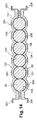
リセプタクル144は、上述した第1実施形態と同様に、1対のエネルギー蓄積ユニット20を受容するようになっている。これらのリセプタクル144は、エネルギー蓄積ユニット20の筒状外面を受容するのに適当な寸法形状の2個の半円筒状部で仕切られている。各リセプタクル144は、全体的に「8」の字の半分の形状である。各対の2個のエネルギー蓄積ユニット20は、この例では、相互に横断線により局所的に接触している。変形例として、図10の如く非接触とすることもある。リセプタクル144の内面及び対をなすエネルギー蓄積ユニット20の筒状外面間には、遊びを設けることなく、熱伝導層54が図2〜図5の第1実施形態と同様に、ラジアル方向に設けられている。この熱伝導層54は、例えば熱伝導性樹脂からなっている。トレイ134は例えばアルミニウム製である。変形例として、熱伝導性接着剤を上述したように使用することも可能である。
The
トレイ134は、矩形のプレート状であり、横断方向に中空状であって、3対のリセプタクル144が形成され、3対のウルトラキャパシタであるエネルギー蓄積ユニット20が受容される。
The
このトレイ134は、例えば金属製である。本発明の一実施形態においては、アルミニウム製である。
The
このトレイ134は、横方向の両端に、カバー132を固定するための2個の横断方向の起立部139を有し、長手方向には2個のクロス部材142を有する。各クロス部材142の両端には、それぞれ開口を有するラグ135が設けられ、各クロス部材は、起立部139の端部に連結されている。
The
アップライト142は、冷たい取付用部材との接触面積を増大させている。 The upright 142 increases the contact area with the cold mounting member.
図11に示す如く、ラグ135は、ハウジング32を、例えば車両のボディワークの如き冷たい部材に取り付けるためのものである。この例では、取り付けは、ラグ13の開口へ挿入したねじ137、各種リベット、ボルト又はスタッド等により行われる。
As shown in FIG. 11, the
図12に示す如く、エネルギー蓄積ユニット20の端子42間の電気的接続バー45、及び複数の電子部品よりなるプリント回路145が設けられている。エネルギー蓄積ユニット20が、ウルトラキャパシタ又はスーパーキャパシタよりなる場合のバランスをとり、これらのユニットは、一様に充電されるようにする。
As shown in FIG. 12, an
この例では、接続バー45及びプリント回路145により直列接続された複数のエネルギー蓄積ユニット20は、トレイ134内に取り付けられたモジュール120を予め形成し、保護カバー132により覆われる。
In this example, the plurality of
この保護カバー132は、モジュール120を覆うと共に保持している。
The
変形例として、保護カバー132に、トレイ134の如きリセプタクルを設け、エネルギー蓄積ユニット20を、半円筒形のリセプタクルと、トレイ134と対向するカバー132とで挟むこともできる。
As a modification, the
この電源装置のあらゆる組み合わせ及び変形が可能である。 All combinations and variations of this power supply device are possible.
例えば図2〜図5に示す実施形態を、90°回転させ、水平底壁(底面)48を縦向きにすることも可能である。 For example, the embodiment shown in FIGS. 2 to 5 can be rotated by 90 ° so that the horizontal bottom wall (bottom surface) 48 is vertically oriented.
また、変形例として、図11〜図13に示すトレイ134に、図2〜図5と同様の波打つ外壁を設けてもよい。
As a modification, the
更なる変形例として、図11〜図13のカバー132に、トレイ134のような半円筒状のリセプタクルを設けてもよい。
As a further modification, the
この場合には、エネルギー蓄積ユニットのリセプタクルは、2つの部分を有し、かつエネルギー蓄積ユニット20の外面に適合する全体的な寸法と形状を有し、エネルギー蓄積ユニットを受容するようにする。
In this case, the receptacle of the energy storage unit has two parts and has an overall size and shape that fits the outer surface of the
次に、本発明による電源装置の実施形態である上述したタイプのリセプタクルの例を、図14及び図15を参照して説明する。 Next, an example of the above-described type receptacle which is an embodiment of the power supply apparatus according to the present invention will be described with reference to FIGS.
変形例として、図14から明らかな如く、トレイ134及びカバー132を、熱伝導性材料で形成し、かつ図2〜図5及びエネルギー蓄積ユニット20用のリセプタクル34と同様に、波打つ外壁151を設けることもある。
As a modification, as is apparent from FIG. 14, the
これに対して、図2〜図5の実施形態を、90°回転させて、外壁151を横方向になるようにすることもある。
On the other hand, the embodiment of FIGS. 2 to 5 may be rotated 90 degrees so that the
200は、トレイ134及び車両のボディワークの如き冷たい取付部材間の部分的な接触面を示す。201は、保護カバー132の外壁及び空気又は冷たい取付部材間の部分的な接触面を示す。また、154は、エネルギー蓄積ユニット20及びリセプタクル144間の接触面を示す。従って、リセプタクル144の外面は波打っている。
本発明の一実施形態によると、接触面154は、図11〜図13に示す如く、熱伝導性かつ電気的絶縁性の熱伝導体である。
According to one embodiment of the present invention, the
変形例として、図15に示す如く、エネルギー蓄積ユニット20を、例えば熱伝導性材料で形成されたカバー132、及びトレイ134のリセプタクル144と、熱伝導性接着剤を介して接触させる。この変形例において、トレイ134及び冷たい取付部材間の接触面は、平坦な外面を有するトレイ134の全長に渡り設けられている。同様に、トレイ132の外面、及び空気、又は冷たい取付部材間の接触は、カバー132の全長に渡って行われる。
As a modification, as shown in FIG. 15, the
接触面の長さは、適用例に応じて定められることは理解しうると思う。例えば、図14において、少なくとも2面、即ち面200及び201を、相互に連結して単一面とすることができる。 It can be understood that the length of the contact surface is determined according to the application example. For example, in FIG. 14, at least two surfaces, namely surfaces 200 and 201, can be interconnected to form a single surface.
また、上述した面201には、必要に応じて、図8に示す如き複数の突起物を設けることもある。
In addition, the
図15におけるカバー132は、ねじ138等の固定具により、トレイ134に連結されていることに留意されたい。この固定具は、2つのリセプタクル144間の材料の厚さ方向に螺入される。これにより、エネルギー蓄積ユニット20のねじクランプを形成する2個のパーツ132及び134によりハウジングが形成される。
Note that the
エネルギー蓄積ユニット20の数は、アプリケーション、特に必要とする電圧に依存することは理解しうると思う。即ち、エネルギー蓄積ユニット20の数は、6個又は12個、或いはそれ以外の数であってもよい。例えば、エネルギー蓄積ユニット20は、6個のウルトラキャパシタ、及び2個の通常のバッテリである。
図10に示す実施形態では、リセプタクル234を縦向きとし、図16に示す如く(横方向の長さ当たりの)エネルギー蓄積ユニット20の数を2倍にしている。
It can be appreciated that the number of
In the embodiment shown in FIG. 10, the
上述した構成により、ハウジング32の軸方向の長さを一定にし、ハウジング32の厚さを増大させることができる。
With the above-described configuration, the axial length of the
このことは、図17に示す如く、図15の実施形態に適用可能である。 This is applicable to the embodiment of FIG. 15, as shown in FIG.
ハウジング32は、車両のブート又は乗車空間等の保護されたエリアに取付可能である。
The
図11〜図15に示すエネルギー蓄積ユニット20、及び図11〜図15に示すトレイを、縦向きにしてもよいことは明らかである。
Obviously, the
変形例として、エネルギー蓄積ユニット20の断面は、円形以外であってもよいことは明らかである。例えば、エネルギー蓄積ユニット20の断面を、楕円又は多角形とする。このことは、エネルギー蓄積ユニット20を受容するリセプタクルについても当てはまる。
As a variant, it is obvious that the cross section of the
リセプタクルは、横向き又は縦向きであってもよい。例えば、図16のハウジング32は、8個のエネルギー蓄積ユニット20を受容可能である。この場合、ハウジング32は、2個の垂直リセプタクル234、及び2個の水平リセプタクルを備えている。
The receptacle may be horizontal or vertical. For example, the
複数のエネルギー蓄積ユニット20を、並列に取り付け、各々直列に取り付けられた2つのグループから構成してもよい。
The plurality of
本発明の電源装置のトレイ32、34、134及び334により、エネルギー蓄積ユニット20による発熱は急速に放熱され、その結果、エネルギー蓄積ユニット20の許容動作温度を超える急激な温度上昇の阻止が可能となっている。
Due to the
さらに、熱伝導性層の存在により、熱を伝導によって放熱することが可能であり、熱の通過を阻害する空気のエリアは除去される。 In addition, the presence of the thermally conductive layer allows heat to be dissipated by conduction, eliminating areas of air that impede the passage of heat.
トレイを熱伝導性材料で形成することにより、複数のエネルギー蓄積ユニット20の温度をほぼ均一に保つことが可能である。
このトレイは、エネルギー蓄積ユニット20、及び冷たい取付部材と間接的に接触している。本発明の一実施形態によると、この冷却源は、車両のボディワークのおける金属の薄板である。変形例として、少なくとも1個のペルチェ効果セルとし、下面を高温とし、冷たい上面をトレイと接触させることもある。
By forming the tray with a heat conductive material, the temperature of the plurality of
This tray is in indirect contact with the
また、変形例として、冷気の流れが、図10に示す複数のフィンのように、トレイと一体形成された複数の突起を掃引するようにすることもある。 As a modification, the cold air flow may sweep a plurality of protrusions integrally formed with the tray like the plurality of fins shown in FIG.
空気流の循環は、例えばエネルギー蓄積ユニット20の温度に基づいて制御される、少なくとも1個のファンにより行われる。
The circulation of the air flow is performed by at least one fan, which is controlled based on the temperature of the
また、少なくとも1個のヒートパイプを、トレイ及び例えば冷たいプレートである冷たい取り付け部材間に接続してもよい。更に、変形例として、トレイ及びカバーを、熱伝導性かつ電気絶縁性材料で製造してもよい。 Also, at least one heat pipe may be connected between the tray and a cold mounting member, for example a cold plate. Further, as a modified example, the tray and the cover may be made of a heat conductive and electrically insulating material.
エネルギー蓄積ユニット20の外面が電気的絶縁性である場合には、図15及び図17に示すトレイ及びカバーは、金属製であってもよい。
When the outer surface of the
熱導電性層54の材料が電気的絶縁性であれば、トレイは、導電性又は電気的絶縁性の何れであってもよい。この層により、各対のエネルギー蓄積ユニット20の温度を一層均一にすることが可能である。
If the material of the thermally
図示の例において、複数のエネルギー蓄積ユニット20は、対として相互に接触して取り付けられている。これにより、複数のエネルギー蓄積ユニット20の温度を、更に均一にすることが可能であることが理解できよう。
In the illustrated example, the plurality of
また、横方向リセプタクル144及び234は、仕切壁であり、下側トレイ32、34、134及び334は、エネルギー蓄積ユニット20を支持するトレイであることに留意されたい。
It should also be noted that the
また、全体的に略「8」の字状のリセプタクルは、細長い形状を有することに留意されたい。 It should also be noted that the generally “8” shaped receptacle generally has an elongated shape.
一例として、使用する樹脂は、その1つが硬化材である2個のコンポーネントを有するポリウレタン系樹脂でもよい。例えば、RAIGI社からRAIGITANE 4759/RAIGIDURHRの記号で市販されている2コンポーネント樹脂であり、この樹脂は、室温で液状ポリウレタンでる。この黒色樹脂は、可撓性(50ショアHR)を有し、優れた熱衝撃特性を有し、かつ金属やプラスチック部品に対して良好な接着性を有する。従って、この樹脂は、接着性樹脂である。 As an example, the resin used may be a polyurethane resin having two components, one of which is a curing material. For example, a two-component resin commercially available from RAIGI under the symbol RAIGITANE 4759 / RAIGIDURHR, which is a liquid polyurethane at room temperature. This black resin has flexibility (50 Shore HR), has excellent thermal shock characteristics, and has good adhesion to metal and plastic parts. Therefore, this resin is an adhesive resin.
変形例として、WEVO社から市販されているショア硬度が50−55であるPD4431FL樹脂、及び300硬化材の2成分ポリウレタン系樹脂を使用してもよい。 As a modification, a PD4431FL resin having a Shore hardness of 50-55 commercially available from WEVO and a two-component polyurethane resin of 300 curing material may be used.
以上、本発明の好適な実施形態について詳述した。しかし、これらの実施形態は、本発明の単なる例示に過ぎず、何ら本発明を限定するものではない。なお、上述した説明に基づいて、特定用途に応じて、種々の変形変更が可能であることは、当業者には容易に理解されると思う。 The preferred embodiments of the present invention have been described in detail above. However, these embodiments are merely examples of the present invention and do not limit the present invention. Based on the above description, it will be easily understood by those skilled in the art that various modifications and changes can be made according to the specific application.
10 電源装置
20 エネルギー蓄積ユニット(ウルトラキャパシタ)
32 トレイ
34 トレイ
36 筒状面
42 端子
43 壁
44 リセプタクル
44’ リセプタクル
45 電気的接続バー
46 壁の内面
48 水平底壁
50 開口
51 壁の外面
52 壁の外面
54 熱導電性層
56 熱伝導性接着剤
60 フィン
120 モジュール
132 保護カバー
134 トレイ
135 ラグ
137 ねじ
138 ねじ
139 起立部
140 孔
141 孔
142 クロス部材
144 横方向リセプタクル
144’ 隔壁
145 プリント回路
151 壁の外面
154 接触面
200 接触面
201 接触面
234 リセプタクル
334 トレイ
10
32 trays
34
44 '
48
51 wall exterior
52
140 holes
141
144 ' Bulkhead 145 Printed
334 trays
Claims (10)
熱伝導性接着剤または熱伝導性樹脂から成る熱伝導層(54)が、蓄積ユニット(20)と、関連するリセプタクル(44)(144)(234)の壁(43)の内面(46)との間に、遊びなしに挿入され、蓄積ユニット(20)による熱が、リセプタクル(44)(144)(234)の壁(43)の内面(46)へ直接伝導されるようになっている車両用電源装置(10)であって、
前記熱伝導性樹脂及び前記熱伝導性接着剤は、電気的絶縁体であること、
前記熱伝導性樹脂は、前記エネルギー蓄積ユニット(20)と前記リセプタクル(44)(144)(234)の前記壁(43)との間に硬化状態で注入されており、前記エネルギー蓄積ユニット(20)は、前記リセプタクル(44)(144)(234)内に固定されていること、
前記リセプタクル(44)(144)(234)の外面(51)(151)は波打っていること、及び
各リセプタクル(44)(144)(234)は、上面に開口(50)を有し、その底面は水平底壁(48)で閉鎖されていて、前記エネルギー蓄積ユニット(20)は、リセプタクル(44)(144)(234)の水平底壁(48)に熱伝導性接着剤(56)の層により固定されていることを特徴とする車両用電源装置(10)。 A vehicle power supply device (10) comprising trays (32) (34) (134) (334) for accommodating at least one large-capacity electric energy storage unit (20) capable of generating heat, the tray ( 32) (34) (134) (334) comprises at least one receptacle (44) (144) (234) for receiving at least one electrical energy storage unit (20), said tray (32) (34) (134) (334) is made of a heat conductive material, and heat from the storage unit is transferred from the inner surface (46) of the wall (43) of the receptacle (44) (144) (234) to the outer surface (51) (52). The tray is divided into a plurality of receptacles (44) (44 ′) (144), and the receptacles (44) (44). ') (144) are each adapted to accommodate at least one storage unit (20), and the wall (43) of each receptacle is made of said thermally conductive material,
A thermally conductive layer (54) comprising a thermally conductive adhesive or a thermally conductive resin is connected to the storage unit (20) and the inner surface (46) of the wall (43) of the associated receptacle (44) (144) (234). Between which the heat from the storage unit (20) is conducted directly to the inner surface (46) of the wall (43) of the receptacle (44) (144) (234) Power supply device (10),
The thermally conductive resin and the thermally conductive adhesive are electrical insulators;
The thermally conductive resin is injected in a cured state between the energy storage unit (20) and the wall (43) of the receptacle (44) (144) (234), and the energy storage unit (20 ) Is fixed in the receptacle (44) (144) (234);
The outer surfaces (51), (151) of the receptacles (44), (144), (234) are wavy, and each receptacle (44), (144), (234) has an opening (50) on the upper surface, The bottom surface is closed by a horizontal bottom wall (48), and the energy storage unit (20) is connected to the horizontal bottom wall (48) of the receptacle (44) (144) (234) by a heat conductive adhesive (56). vehicle power supply device according to claim that you are fixed by a layer (10).
Applications Claiming Priority (3)
| Application Number | Priority Date | Filing Date | Title |
|---|---|---|---|
| FR0759606 | 2007-12-06 | ||
| FR0759606A FR2924857B1 (en) | 2007-12-06 | 2007-12-06 | ELECTRICAL SUPPLY DEVICE COMPRISING A RECEPTION UNIT FOR ULTRA CAPACITY STORAGE UNITS |
| PCT/FR2008/052201 WO2009080936A2 (en) | 2007-12-06 | 2008-12-04 | Electrical power supply device comprising a tray for accommodating ultra-high capacity storage units |
Publications (2)
| Publication Number | Publication Date |
|---|---|
| JP2011508366A JP2011508366A (en) | 2011-03-10 |
| JP5543358B2 true JP5543358B2 (en) | 2014-07-09 |
Family
ID=39580117
Family Applications (1)
| Application Number | Title | Priority Date | Filing Date |
|---|---|---|---|
| JP2010536518A Expired - Fee Related JP5543358B2 (en) | 2007-12-06 | 2008-12-04 | Vehicle power supply |
Country Status (9)
| Country | Link |
|---|---|
| US (1) | US8582294B2 (en) |
| EP (1) | EP2223364B1 (en) |
| JP (1) | JP5543358B2 (en) |
| KR (1) | KR20100100943A (en) |
| CN (1) | CN101926022A (en) |
| BR (1) | BRPI0819888A2 (en) |
| FR (1) | FR2924857B1 (en) |
| MX (1) | MX2010006159A (en) |
| WO (1) | WO2009080936A2 (en) |
Cited By (1)
| Publication number | Priority date | Publication date | Assignee | Title |
|---|---|---|---|---|
| KR102021479B1 (en) * | 2018-09-19 | 2019-09-16 | (주)엔이피콘 | The Heat Dissipation Case of The Power Capacitor |
Families Citing this family (62)
| Publication number | Priority date | Publication date | Assignee | Title |
|---|---|---|---|---|
| DE102009030017A1 (en) * | 2009-06-23 | 2010-12-30 | Bayerische Motoren Werke Aktiengesellschaft | Device for supplying power to a motor vehicle with a radiator block |
| DE102009030016A1 (en) | 2009-06-23 | 2010-12-30 | Bayerische Motoren Werke Aktiengesellschaft | Device for powering a motor vehicle with a radiator block |
| JP5496576B2 (en) * | 2009-08-26 | 2014-05-21 | 三洋電機株式会社 | Battery pack |
| JP2011113722A (en) * | 2009-11-25 | 2011-06-09 | Sanyo Electric Co Ltd | Battery pack |
| JP5221820B1 (en) * | 2011-05-30 | 2013-06-26 | パナソニック株式会社 | Battery block and manufacturing method thereof |
| JP5617765B2 (en) * | 2011-06-06 | 2014-11-05 | 三菱自動車工業株式会社 | Assembled battery |
| DE102011077166A1 (en) * | 2011-06-08 | 2012-12-13 | Bayerische Motoren Werke Aktiengesellschaft | Power supply device for motor vehicle, has cooling module having successively arranged and electrically interconnected cooling sections |
| US9030822B2 (en) | 2011-08-15 | 2015-05-12 | Lear Corporation | Power module cooling system |
| DE102011056417B4 (en) * | 2011-12-14 | 2020-01-09 | Johnson Controls Autobatterie Gmbh & Co. Kgaa | Accumulator and method for its production |
| US9076593B2 (en) * | 2011-12-29 | 2015-07-07 | Lear Corporation | Heat conductor for use with an inverter in an electric vehicle (EV) or a hybrid-electric vehicle (HEV) |
| US8971041B2 (en) | 2012-03-29 | 2015-03-03 | Lear Corporation | Coldplate for use with an inverter in an electric vehicle (EV) or a hybrid-electric vehicle (HEV) |
| US8971038B2 (en) | 2012-05-22 | 2015-03-03 | Lear Corporation | Coldplate for use in an electric vehicle (EV) or a hybrid-electric vehicle (HEV) |
| US8902582B2 (en) | 2012-05-22 | 2014-12-02 | Lear Corporation | Coldplate for use with a transformer in an electric vehicle (EV) or a hybrid-electric vehicle (HEV) |
| JP5672294B2 (en) * | 2012-11-30 | 2015-02-18 | トヨタ自動車株式会社 | Battery pack and vehicle |
| KR101636378B1 (en) * | 2013-08-28 | 2016-07-05 | 주식회사 엘지화학 | Module Housing for Unit Module Having Heat Radiation Structure and Battery Module Comprising the Same |
| JP6301240B2 (en) * | 2014-02-07 | 2018-03-28 | 本田技研工業株式会社 | Battery charger for vehicle |
| US9731609B2 (en) | 2014-04-04 | 2017-08-15 | Dg Systems Llc | Vehicle power sharing and grid connection system for electric motors and drives |
| US9615490B2 (en) | 2014-05-15 | 2017-04-04 | Lear Corporation | Coldplate with integrated DC link capacitor for cooling thereof |
| US9362040B2 (en) | 2014-05-15 | 2016-06-07 | Lear Corporation | Coldplate with integrated electrical components for cooling thereof |
| CN103986309A (en) * | 2014-05-23 | 2014-08-13 | 台达电子企业管理(上海)有限公司 | Direct-current capacitor module and laminated busbar structure thereof |
| EP2952377B1 (en) | 2014-06-03 | 2017-10-04 | Visedo Oy | A capacitor module for a mobile working machine |
| WO2016027978A1 (en) * | 2014-08-19 | 2016-02-25 | 엘에스엠트론 주식회사 | Energy storage device having improved heat-dissipation characteristic |
| US10115531B2 (en) | 2014-08-19 | 2018-10-30 | Ls Mitron Ltd. | Energy storage device having improved heat-dissipation characteristic |
| CN106716675B (en) * | 2014-10-17 | 2020-02-28 | 三洋电机株式会社 | Battery pack |
| US9458854B2 (en) | 2014-11-21 | 2016-10-04 | Arista Networks, Inc. | Electrical connection mechanism for reversible fan module |
| US9433124B2 (en) | 2014-11-21 | 2016-08-30 | Arista Networks, Inc. | Reversible fan module |
| US9674990B2 (en) * | 2015-01-23 | 2017-06-06 | Rockwell Automation Technoloies, Inc. | Devices and methods for cooling bus capacitors |
| JP6256397B2 (en) * | 2015-03-23 | 2018-01-10 | トヨタ自動車株式会社 | Battery pack |
| DE102015111541B4 (en) * | 2015-07-16 | 2023-07-20 | Halla Visteon Climate Control Corporation | Method of making a connection between at least one cylindrical electrolytic capacitor and a heat sink |
| JP6380270B2 (en) * | 2015-07-21 | 2018-08-29 | トヨタ自動車株式会社 | Battery module and battery module manufacturing method |
| JP6620478B2 (en) * | 2015-09-14 | 2019-12-18 | 株式会社豊田自動織機 | Battery pack and battery module |
| CN108140766B (en) * | 2015-09-29 | 2021-03-30 | 株式会社杰士汤浅国际 | Power storage device and method for manufacturing power storage device |
| DE102015118605A1 (en) * | 2015-10-30 | 2017-07-27 | Dr. Ing. H.C. F. Porsche Aktiengesellschaft | Energy storage for a vehicle and method for producing an energy storage |
| US11296370B2 (en) * | 2015-12-03 | 2022-04-05 | Eaglepicher Technologies, Llc | Battery having high thermal conductivity case |
| CN105514306B (en) * | 2015-12-24 | 2019-05-17 | 北京航空航天大学 | A kind of dumbbell shaped lithium ion battery case and its stacking method |
| EP3419082B1 (en) | 2016-04-01 | 2021-06-16 | LG Chem, Ltd. | Battery module |
| US11043822B2 (en) * | 2016-10-04 | 2021-06-22 | Brown & Watson International Pty Ltd | Apparatus for jump starting a vehicle |
| KR102057232B1 (en) * | 2017-03-15 | 2019-12-18 | 주식회사 엘지화학 | Battery module, battery pack comprising the battery module and vehicle comprising the battery pack |
| JP6719409B2 (en) * | 2017-03-17 | 2020-07-08 | 株式会社キトー | Electric hoist |
| WO2019005537A1 (en) * | 2017-06-30 | 2019-01-03 | Avx Corporation | Heat dissipation from a balancing circuit for an ultracapacitor module |
| CA3069342A1 (en) * | 2017-07-13 | 2019-01-17 | Econtrols, Llc | Modular lithium-ion battery system for fork lifts |
| KR102258178B1 (en) * | 2017-10-27 | 2021-06-03 | 주식회사 엘지에너지솔루션 | Battery module simplified cooling and assembling structure and Method for manufacturing the same |
| KR102204303B1 (en) * | 2017-10-27 | 2021-01-15 | 주식회사 엘지화학 | Battery module having fixing structure intergrated with cooling material for battery cells and Battery pack including the same |
| KR102382382B1 (en) | 2018-07-03 | 2022-04-01 | 주식회사 엘지에너지솔루션 | Battery Module Having Heat-Shrinkable Tube |
| KR102243578B1 (en) * | 2018-07-23 | 2021-04-21 | 주식회사 엘지화학 | Secondary Battery Pack |
| US11145932B2 (en) | 2018-09-24 | 2021-10-12 | Milwaukee Electric Tool Corporation | Battery cell module and battery pack |
| US11556725B2 (en) * | 2018-10-12 | 2023-01-17 | Rimage Corporation | Automated storage unit publisher |
| KR102378527B1 (en) | 2018-12-05 | 2022-03-23 | 주식회사 엘지에너지솔루션 | Battery module and the method of manufacturing the same |
| FR3090211B1 (en) * | 2018-12-14 | 2022-08-19 | Valeo Siemens Eautomotive France Sas | Assembly of a capacitive block with integrated retainers |
| KR102694746B1 (en) | 2019-01-10 | 2024-08-12 | 주식회사 엘지에너지솔루션 | Method for Preparing Battery Pack |
| CN109887745A (en) * | 2019-01-18 | 2019-06-14 | 柯贝尔电能质量技术(上海)有限公司 | A kind of MHFC copper sheet |
| DE102019204200A1 (en) * | 2019-03-27 | 2020-10-01 | Robert Bosch Gmbh | Capacitor, in particular intermediate circuit capacitor for a multi-phase system |
| DE102019205491A1 (en) * | 2019-04-16 | 2020-06-10 | Siemens Aktiengesellschaft | Arrangement for cooling a condenser, converter and vehicle |
| KR20210000551A (en) * | 2019-06-25 | 2021-01-05 | 주식회사 엘지화학 | Battery pack and device including the same |
| DE102019215775A1 (en) * | 2019-10-14 | 2021-04-15 | Robert Bosch Gmbh | Battery module with at least one single cell and a cell holder for receiving the at least one single cell and a method for producing such a battery module |
| CN111599595B (en) * | 2020-04-27 | 2021-12-17 | 铜陵市胜美达电子制造有限公司 | Explosion-proof type rapid combined capacitor |
| WO2022002255A1 (en) * | 2020-07-03 | 2022-01-06 | 苏州宝时得电动工具有限公司 | Battery pack, and manufacturing method therefor |
| KR102332168B1 (en) * | 2020-12-10 | 2021-12-01 | (주)뉴인텍 | Case Molding Capacitor With Plastic PLastic Plate |
| KR20220101474A (en) * | 2021-01-11 | 2022-07-19 | 주식회사 엘지에너지솔루션 | Battery pack, appatatus and method for manufacturing the battery pack |
| CA3218420A1 (en) | 2021-06-04 | 2022-12-08 | Kennon Guglielmo | Lithium-ion battery charging system for fork lifts |
| KR20230059610A (en) * | 2021-10-26 | 2023-05-03 | 주식회사 엘지에너지솔루션 | Cell tray |
| JP2024526358A (en) * | 2021-11-15 | 2024-07-17 | エルジー エナジー ソリューション リミテッド | Battery module and battery pack including same |
Family Cites Families (34)
| Publication number | Priority date | Publication date | Assignee | Title |
|---|---|---|---|---|
| JPS4811617Y1 (en) * | 1968-04-15 | 1973-03-29 | ||
| DE2624724A1 (en) * | 1976-06-02 | 1977-12-15 | Licentia Gmbh | ELECTRIC CAPACITOR |
| FR2492577A1 (en) * | 1980-10-16 | 1982-04-23 | Alsthom Atlantique | Insulating enclosures for three phase electrical power condensers - involving a plastic box with laminate board partitions to contain potting resins without a dedicated mould |
| JPS6276513A (en) * | 1985-09-27 | 1987-04-08 | 利昌工業株式会社 | High voltage capacitor |
| JP3458239B2 (en) * | 1993-06-17 | 2003-10-20 | 三菱アルミニウム株式会社 | In-vehicle battery case |
| JP3401568B2 (en) * | 1993-08-04 | 2003-04-28 | 株式会社東京アールアンドデー | Mounting mechanism for cylindrical batteries for electric vehicles |
| BE1010663A5 (en) * | 1996-10-02 | 1998-11-03 | Asea Brown Boveri Jumet S A En | Capacitor. |
| FR2761203B1 (en) * | 1997-03-24 | 1999-05-28 | Alsthom Cge Alcatel | DEVICE FOR MANAGING THE TEMPERATURE OF A BATTERY OF ELECTROCHEMICAL GENERATORS |
| JPH11213976A (en) * | 1998-01-21 | 1999-08-06 | Nissan Motor Co Ltd | Battery fixing structure and battery cooling method of electric vehicle |
| DE19814700A1 (en) * | 1998-04-01 | 1999-10-07 | Vishay Electronic Gmbh | Power capacitor |
| JP4870858B2 (en) * | 1998-08-06 | 2012-02-08 | 株式会社東芝 | Battery pack |
| JP4176884B2 (en) * | 1998-10-08 | 2008-11-05 | ポリマテック株式会社 | Battery storage structure and storage method for electric vehicle |
| DE19857840C2 (en) * | 1998-12-15 | 2003-10-02 | Siemens Ag | Electronic device |
| JP2001307784A (en) * | 2000-04-20 | 2001-11-02 | Japan Storage Battery Co Ltd | Battery set |
| JP2002184374A (en) * | 2000-12-12 | 2002-06-28 | Honda Motor Co Ltd | Cell pack |
| JP2002216726A (en) * | 2001-01-17 | 2002-08-02 | Sony Corp | Case for storing battery and battery element |
| US6541942B1 (en) * | 2001-11-13 | 2003-04-01 | Aerovironment, Inc. | Capacitor tub assembly and method of cooling |
| DE10214367B4 (en) | 2002-03-30 | 2006-08-24 | Robert Bosch Gmbh | Energy storage module and hand tool |
| JP4237452B2 (en) * | 2002-08-01 | 2009-03-11 | パナソニック株式会社 | Battery pack and manufacturing method thereof |
| JP2005056837A (en) * | 2003-07-22 | 2005-03-03 | Polymatech Co Ltd | Thermally conductive holder |
| WO2005029519A1 (en) * | 2003-09-18 | 2005-03-31 | Matsushita Electric Industrial Co., Ltd. | Capacitor unit |
| WO2005029674A1 (en) * | 2003-09-18 | 2005-03-31 | Matsushita Electric Industrial Co., Ltd. | Capacitor unit |
| JP2006092935A (en) * | 2004-09-24 | 2006-04-06 | Teijin Pharma Ltd | Battery pack |
| US7440258B2 (en) * | 2005-03-14 | 2008-10-21 | Maxwell Technologies, Inc. | Thermal interconnects for coupling energy storage devices |
| FR2883670B1 (en) * | 2005-03-25 | 2010-10-15 | Valeo Equip Electr Moteur | COMPACT POWER SUPPLY DEVICE FOR A MOTOR VEHICLE |
| JP4859443B2 (en) * | 2005-11-17 | 2012-01-25 | 日立オートモティブシステムズ株式会社 | Power converter |
| US8496499B2 (en) * | 2006-04-05 | 2013-07-30 | Pulse Electronics, Inc. | Modular electronic header assembly and methods of manufacture |
| EP2110824A4 (en) * | 2007-02-16 | 2015-02-25 | Panasonic Corp | CAPACITOR UNIT AND METHOD FOR MANUFACTURING THE SAME |
| FR2915626B1 (en) * | 2007-04-24 | 2010-10-29 | Batscap Sa | MODULE FOR ELECTRIC ENERGY STORAGE ASSEMBLY |
| US8134343B2 (en) * | 2007-04-27 | 2012-03-13 | Flextronics International Kft | Energy storage device for starting engines of motor vehicles and other transportation systems |
| FR2926060B1 (en) * | 2008-01-04 | 2009-12-11 | Valeo Equip Electr Moteur | METHOD FOR DISASSEMBLING A DEVICE COMPRISING AT LEAST ONE ARTICLE NOISED AT LEAST PARTIALLY IN A RESIN |
| DE102008056859B4 (en) * | 2008-11-12 | 2022-08-11 | Bayerische Motoren Werke Aktiengesellschaft | Device for supplying voltage to a motor vehicle with a cooling device |
| JP5330810B2 (en) * | 2008-11-18 | 2013-10-30 | 株式会社日立製作所 | Battery box for storing battery module and railcar equipped with the same |
| US20100157527A1 (en) * | 2008-12-23 | 2010-06-24 | Ise Corporation | High-Power Ultracapacitor Energy Storage Pack and Method of Use |
-
2007
- 2007-12-06 FR FR0759606A patent/FR2924857B1/en not_active Expired - Fee Related
-
2008
- 2008-12-04 EP EP08865152.6A patent/EP2223364B1/en not_active Not-in-force
- 2008-12-04 JP JP2010536518A patent/JP5543358B2/en not_active Expired - Fee Related
- 2008-12-04 BR BRPI0819888-8A patent/BRPI0819888A2/en not_active IP Right Cessation
- 2008-12-04 MX MX2010006159A patent/MX2010006159A/en active IP Right Grant
- 2008-12-04 KR KR1020107014869A patent/KR20100100943A/en not_active Application Discontinuation
- 2008-12-04 CN CN2008801257580A patent/CN101926022A/en active Pending
- 2008-12-04 WO PCT/FR2008/052201 patent/WO2009080936A2/en active Application Filing
- 2008-12-04 US US12/745,947 patent/US8582294B2/en active Active
Cited By (1)
| Publication number | Priority date | Publication date | Assignee | Title |
|---|---|---|---|---|
| KR102021479B1 (en) * | 2018-09-19 | 2019-09-16 | (주)엔이피콘 | The Heat Dissipation Case of The Power Capacitor |
Also Published As
| Publication number | Publication date |
|---|---|
| US8582294B2 (en) | 2013-11-12 |
| CN101926022A (en) | 2010-12-22 |
| EP2223364B1 (en) | 2017-01-11 |
| EP2223364A2 (en) | 2010-09-01 |
| JP2011508366A (en) | 2011-03-10 |
| KR20100100943A (en) | 2010-09-15 |
| FR2924857B1 (en) | 2014-06-06 |
| WO2009080936A2 (en) | 2009-07-02 |
| MX2010006159A (en) | 2010-07-01 |
| FR2924857A1 (en) | 2009-06-12 |
| BRPI0819888A2 (en) | 2015-06-16 |
| US20110090614A1 (en) | 2011-04-21 |
| WO2009080936A3 (en) | 2009-10-08 |
Similar Documents
| Publication | Publication Date | Title |
|---|---|---|
| JP5543358B2 (en) | Vehicle power supply | |
| CN100562227C (en) | Cooling structure of electrical components | |
| US7333331B2 (en) | Power unit device and power converter device | |
| US8919424B2 (en) | Semiconductor element cooling structure | |
| KR20080050413A (en) | Automotive small electricity supply | |
| KR101000594B1 (en) | Integrated power converter of fuel cell vehicle | |
| US20080193832A1 (en) | Device for Supplying Electric Power to a Motor Vehicle | |
| US8662225B2 (en) | Built-in equipment for micro-hybrid device for automotive vehicle and micro-hybrid device comprising the same | |
| KR101034063B1 (en) | Film Capacitor | |
| KR102326063B1 (en) | Film capacitor module of inverter for vehicle | |
| US20090142654A1 (en) | Compact power supply device for a motor vehicle comprising regulated cooling means | |
| KR20100011033A (en) | Structure of dc input film capacitor in inverter for improving cooling performance | |
| JP2007282369A (en) | Power converter | |
| US20200195189A1 (en) | Power conversion unit | |
| KR100925952B1 (en) | Film Capacitor Module of Inverter with Improved Cooling Performance | |
| JP7606969B2 (en) | Power supply device, electric vehicle using the same, and power storage device | |
| JP2011177024A (en) | Power conversion apparatus | |
| US20230156979A1 (en) | Converter module | |
| US20240195316A1 (en) | Cooled High-Current System | |
| KR20140044019A (en) | Holder for improving shock and vibration of capacitor, and housing assembly for on board charger using the same | |
| JP2008148529A (en) | Voltage converter | |
| WO2022113630A1 (en) | Power conversion device | |
| WO2018211580A1 (en) | Power conversion apparatus | |
| KR102756060B1 (en) | Electronic component assembly | |
| JP2014150215A (en) | Cooling device and motor control device including the same |
Legal Events
| Date | Code | Title | Description |
|---|---|---|---|
| A621 | Written request for application examination |
Free format text: JAPANESE INTERMEDIATE CODE: A621 Effective date: 20111027 |
|
| A977 | Report on retrieval |
Free format text: JAPANESE INTERMEDIATE CODE: A971007 Effective date: 20130613 |
|
| A131 | Notification of reasons for refusal |
Free format text: JAPANESE INTERMEDIATE CODE: A131 Effective date: 20130618 |
|
| A601 | Written request for extension of time |
Free format text: JAPANESE INTERMEDIATE CODE: A601 Effective date: 20130917 |
|
| A602 | Written permission of extension of time |
Free format text: JAPANESE INTERMEDIATE CODE: A602 Effective date: 20130925 |
|
| A601 | Written request for extension of time |
Free format text: JAPANESE INTERMEDIATE CODE: A601 Effective date: 20131017 |
|
| A602 | Written permission of extension of time |
Free format text: JAPANESE INTERMEDIATE CODE: A602 Effective date: 20131024 |
|
| A521 | Request for written amendment filed |
Free format text: JAPANESE INTERMEDIATE CODE: A523 Effective date: 20131028 |
|
| A131 | Notification of reasons for refusal |
Free format text: JAPANESE INTERMEDIATE CODE: A131 Effective date: 20131119 |
|
| A521 | Request for written amendment filed |
Free format text: JAPANESE INTERMEDIATE CODE: A523 Effective date: 20131225 |
|
| TRDD | Decision of grant or rejection written | ||
| A01 | Written decision to grant a patent or to grant a registration (utility model) |
Free format text: JAPANESE INTERMEDIATE CODE: A01 Effective date: 20140408 |
|
| A61 | First payment of annual fees (during grant procedure) |
Free format text: JAPANESE INTERMEDIATE CODE: A61 Effective date: 20140508 |
|
| R150 | Certificate of patent or registration of utility model |
Ref document number: 5543358 Country of ref document: JP Free format text: JAPANESE INTERMEDIATE CODE: R150 |
|
| R250 | Receipt of annual fees |
Free format text: JAPANESE INTERMEDIATE CODE: R250 |
|
| LAPS | Cancellation because of no payment of annual fees |