JP5507096B2 - Manufacturing method of dental probe - Google Patents
Manufacturing method of dental probe Download PDFInfo
- Publication number
- JP5507096B2 JP5507096B2 JP2009052093A JP2009052093A JP5507096B2 JP 5507096 B2 JP5507096 B2 JP 5507096B2 JP 2009052093 A JP2009052093 A JP 2009052093A JP 2009052093 A JP2009052093 A JP 2009052093A JP 5507096 B2 JP5507096 B2 JP 5507096B2
- Authority
- JP
- Japan
- Prior art keywords
- optical fiber
- probe
- coating layer
- lumen tube
- dental
- Prior art date
- Legal status (The legal status is an assumption and is not a legal conclusion. Google has not performed a legal analysis and makes no representation as to the accuracy of the status listed.)
- Active
Links
Images


Classifications
-
- A—HUMAN NECESSITIES
- A61—MEDICAL OR VETERINARY SCIENCE; HYGIENE
- A61B—DIAGNOSIS; SURGERY; IDENTIFICATION
- A61B18/00—Surgical instruments, devices or methods for transferring non-mechanical forms of energy to or from the body
- A61B18/18—Surgical instruments, devices or methods for transferring non-mechanical forms of energy to or from the body by applying electromagnetic radiation, e.g. microwaves
- A61B18/20—Surgical instruments, devices or methods for transferring non-mechanical forms of energy to or from the body by applying electromagnetic radiation, e.g. microwaves using laser
- A61B18/22—Surgical instruments, devices or methods for transferring non-mechanical forms of energy to or from the body by applying electromagnetic radiation, e.g. microwaves using laser the beam being directed along or through a flexible conduit, e.g. an optical fibre; Couplings or hand-pieces therefor
-
- A—HUMAN NECESSITIES
- A61—MEDICAL OR VETERINARY SCIENCE; HYGIENE
- A61C—DENTISTRY; APPARATUS OR METHODS FOR ORAL OR DENTAL HYGIENE
- A61C1/00—Dental machines for boring or cutting ; General features of dental machines or apparatus, e.g. hand-piece design
- A61C1/0046—Dental lasers
-
- A—HUMAN NECESSITIES
- A61—MEDICAL OR VETERINARY SCIENCE; HYGIENE
- A61C—DENTISTRY; APPARATUS OR METHODS FOR ORAL OR DENTAL HYGIENE
- A61C1/00—Dental machines for boring or cutting ; General features of dental machines or apparatus, e.g. hand-piece design
- A61C1/02—Dental machines for boring or cutting ; General features of dental machines or apparatus, e.g. hand-piece design characterised by the drive of the dental tools
- A61C1/05—Dental machines for boring or cutting ; General features of dental machines or apparatus, e.g. hand-piece design characterised by the drive of the dental tools with turbine drive
- A61C1/052—Ducts for supplying driving or cooling fluid, e.g. air, water
-
- A—HUMAN NECESSITIES
- A61—MEDICAL OR VETERINARY SCIENCE; HYGIENE
- A61B—DIAGNOSIS; SURGERY; IDENTIFICATION
- A61B18/00—Surgical instruments, devices or methods for transferring non-mechanical forms of energy to or from the body
- A61B18/18—Surgical instruments, devices or methods for transferring non-mechanical forms of energy to or from the body by applying electromagnetic radiation, e.g. microwaves
- A61B18/20—Surgical instruments, devices or methods for transferring non-mechanical forms of energy to or from the body by applying electromagnetic radiation, e.g. microwaves using laser
- A61B18/22—Surgical instruments, devices or methods for transferring non-mechanical forms of energy to or from the body by applying electromagnetic radiation, e.g. microwaves using laser the beam being directed along or through a flexible conduit, e.g. an optical fibre; Couplings or hand-pieces therefor
- A61B2018/2244—Features of optical fibre cables, e.g. claddings
Landscapes
- Health & Medical Sciences (AREA)
- Life Sciences & Earth Sciences (AREA)
- Physics & Mathematics (AREA)
- Public Health (AREA)
- Veterinary Medicine (AREA)
- Animal Behavior & Ethology (AREA)
- General Health & Medical Sciences (AREA)
- Optics & Photonics (AREA)
- Surgery (AREA)
- Dentistry (AREA)
- Oral & Maxillofacial Surgery (AREA)
- Epidemiology (AREA)
- Electromagnetism (AREA)
- Otolaryngology (AREA)
- Nuclear Medicine, Radiotherapy & Molecular Imaging (AREA)
- Engineering & Computer Science (AREA)
- Biomedical Technology (AREA)
- Heart & Thoracic Surgery (AREA)
- Medical Informatics (AREA)
- Molecular Biology (AREA)
- Dental Tools And Instruments Or Auxiliary Dental Instruments (AREA)
- Laser Surgery Devices (AREA)
Description
本発明は、歯科治療用ハンドピースにおいて、光ファイバで伝送されたレーザ光を被照射位置に導くために用いられる歯科用プローブの製造方法に関する。 The present invention relates to a method for manufacturing a dental probe used for guiding a laser beam transmitted by an optical fiber to an irradiation position in a dental treatment handpiece.
近年、歯牙のう(齲)蝕除去、象牙質除去、エナメル質切除等、歯牙の硬質組織の処置を対象とした歯科用レーザ治療装置が提供されるようになっている。
歯科用レーザ治療装置に用いられるレーザハンドピースは、光ファイバから出射したレーザ光を治療部位(被照射位置)に導く先端部分を備えている。この先端部分は、歯牙の治療部位や治療態様に適合した形状及び構造を有するとともに、レーザ光が照射される患部を冷却し、蒸散物を除去可能であることが望ましい。
このため、光ファイバで伝送されたレーザ光を被照射位置に導くプローブを備えるレーザハンドピースにおいて、プローブの出射端近傍で水を噴射する注水管と、プローブの出射端近傍でガス(空気)を噴射する給気管とを備え、プローブの先端部分の形状がレーザハンドピースの軸に対して光ファイバからのレーザ出射方向が斜めとなるようにプローブが形成されたものが知られている(例えば特許文献1参照)。
2. Description of the Related Art In recent years, a dental laser treatment apparatus intended for treatment of hard tissues of teeth such as dental caries (dental) caries removal, dentin removal, enamel excision, and the like has been provided.
A laser handpiece used in a dental laser treatment apparatus includes a tip portion that guides laser light emitted from an optical fiber to a treatment site (irradiation position). It is desirable that the distal end portion has a shape and structure suitable for the treatment site and treatment mode of the tooth, and can cool the affected area irradiated with the laser light and remove the transpiration.
For this reason, in a laser handpiece including a probe that guides laser light transmitted through an optical fiber to an irradiated position, a water injection pipe that injects water near the exit end of the probe, and gas (air) near the exit end of the probe It is known that a probe is formed so that the tip of the probe is shaped so that the laser emission direction from the optical fiber is oblique with respect to the axis of the laser handpiece (for example, a patent) Reference 1).
しかしながら、歯科治療用においては、歯牙の硬質組織を除去するために、パワーが強いレーザ光が照射される。一方、プローブの先端部において光ファイバの先端部を曲げているので、光ファイバの曲げ損失によってレーザ光の一部が光ファイバの外側に漏洩し、その漏洩したパワーが熱に変換されることで、プローブ先端部の温度が上昇する、という問題を生じる。プローブ先端部の温度が上昇すると、患者がプローブ先端部の高熱を感じて不快に感じるおそれがある。また、プローブ先端部の温度上昇が著しい場合は、プローブ先端部の側面が口腔や歯茎等に触れることで、火傷を起こすおそれがある。 However, in dental treatment, a powerful laser beam is irradiated to remove the hard tissue of the tooth. On the other hand, since the tip of the optical fiber is bent at the tip of the probe, a part of the laser light leaks to the outside of the optical fiber due to the bending loss of the optical fiber, and the leaked power is converted into heat. This causes a problem that the temperature of the probe tip increases. When the temperature of the probe tip increases, the patient may feel uncomfortable due to the high temperature of the probe tip. Moreover, when the temperature rise of a probe tip part is remarkable, there exists a possibility of causing a burn, when the side surface of a probe tip part touches an oral cavity or a gum.
本発明は、上記事情に鑑みてなされたものであり、先端部の温度上昇を防ぐことが可能な歯科用プローブの製造方法を提供する。 This invention is made | formed in view of the said situation, and provides the manufacturing method of the dental probe which can prevent the temperature rise of a front-end | tip part.
前記課題を解決するため、本発明は、歯科治療用レーザハンドピースにおいて、光ファイバで伝送されたレーザ光を被照射位置に導くために用いられる歯科用プローブの製造方法であって、水の流路と、エアの流路と、光ファイバが挿通される管路がそれぞれ互いに離隔されて貫通穴として内部に形成された可とう性を有する高分子化合物からなるマルチルーメンチューブと、クラッドの外周上に設けられた樹脂被覆層、および前記樹脂被覆層の外周上に設けられた金属被覆層を有する光ファイバであって、その金属被覆層が前記光ファイバの曲げ変形に対応して変形可能であるとともに、曲げ変形された前記光ファイバの形状を保持可能であり、その樹脂被覆層における屈折率が前記クラッドより低い光ファイバとを用意し、前記マルチルーメンチューブの管路に前記光ファイバを挿通してプローブ先端部を構成し、前記水の流路および前記エアの流路内に着脱可能な補強材を充填し、前記光ファイバおよび前記マルチルーメンチューブの周囲に溶融樹脂を供給して固化させることにより、前記光ファイバの外面形状を型として、光ファイバ通路を有するプローブ本体部を前記マルチルーメンチューブと一体にインサート成形することを特徴とする歯科用プローブの製造方法を提供する。
前記プローブ本体部は、前記マルチルーメンチューブの後端外周に前記マルチルーメンチューブと一体に成形された高分子化合物からなり、前記マルチルーメンチューブにおける前記水の流路および前記エアの流路のそれぞれの後端が前記プローブ本体部内において閉塞され、前記プローブ本体部の側面に設けた2つの切り欠きのそれぞれの内部において、前記マルチルーメンチューブが露出され、その露出部それぞれに前記水の流路又は前記エアの流路についての導入口が設けられていることが好ましい。
前記プローブ本体部を成形する成形金型の内面に前記導入口を塞ぐ凸部を設けて前記溶融樹脂が供給されないようにすることにより、前記切り欠きを形成することが好ましい。
In order to solve the above-mentioned problems , the present invention provides a method for manufacturing a dental probe used for guiding a laser beam transmitted by an optical fiber to an irradiated position in a laser handpiece for dental treatment, which comprises a flow of water. A multi-lumen tube made of a polymer compound having flexibility and formed as a through hole in which a path, an air flow path, a pipe through which an optical fiber is inserted are separated from each other, and on the outer periphery of the cladding resin coating layer provided on, and the an optical fiber to have a metal coating layer provided on the outer periphery of the resin coating layer, deformable the metal coating layer corresponding to the bending deformation of the optical fiber with some, it can hold the shape of the bending deformed the optical fiber, providing a low optical fiber than the refractive index of the cladding in the resin coating layer, the Maruchiru The optical fiber is inserted into the tube of the main tube to form a probe tip, and the water flow channel and the air flow channel are filled with a removable reinforcing material, and the optical fiber and the multi-lumen tube are filled. The probe main body having an optical fiber passage is insert-molded integrally with the multi-lumen tube by supplying a molten resin around and solidifying the outer surface of the optical fiber as a mold . A method for manufacturing a probe is provided.
The probe main body, wherein the rear end outer periphery of the multi-lumen tube multi-lumen tube and Ri Do a polymer compound which is integrally formed, the respective flow path and the air flow path of the water in the multi-lumen tube The rear end is closed in the probe main body, and the multi-lumen tube is exposed inside each of the two notches provided on the side surface of the probe main body. It is preferable that an inlet for the air flow path is provided.
It is preferable that the notch is formed by providing a convex portion for closing the introduction port on the inner surface of a molding die for molding the probe main body so that the molten resin is not supplied.
本発明によれば、樹脂被覆層が、クラッドの屈折率より低い屈折率を有する高分子化合物からなるので、光ファイバにおいて第2のクラッドとして機能し、曲げ損失によるレーザ光の漏洩を抑制することができる。これにより、プローブの温度上昇を防止することができる。 According to the present invention, since the resin coating layer is made of a polymer compound having a refractive index lower than that of the cladding, it functions as the second cladding in the optical fiber and suppresses the leakage of laser light due to bending loss. Can do. Thereby, the temperature rise of a probe can be prevented.
以下、好適な実施の形態に基づき、図面を参照して本発明を説明する。なお、図2および図3においては、プローブ先端部11の中間部を省略して歯科用プローブを現している。
The present invention will be described below based on preferred embodiments with reference to the drawings. In FIGS. 2 and 3, the dental probe is shown with the intermediate portion of the
図1に示すように、本形態例の歯科用プローブ10は、その先端部11が、水の流路31と、エアの流路32と、光ファイバ20が挿通される管路33が内部に形成されたマルチルーメンチューブ30、および管路33に挿通された光ファイバ20からなり、光ファイバ20は、コア21およびクラッド22と、クラッド22の外周上に設けられた樹脂被覆層23、および樹脂被覆層23の外周上に設けられた金属被覆層24を有し、樹脂被覆層23は、屈折率がクラッド22の屈折率より低い高分子化合物からなるものである。
As shown in FIG. 1, the
光ファイバ20のコア21およびクラッド22は、石英系光ファイバ、ポリマークラッド光ファイバ、フッ化物光ファイバ、カルコゲナイドガラス光ファイバ等の各種光ファイバで構成することができる。本形態例では、コア径が通常の通信用光ファイバのコアよりも大きい(例えばコア径400μm)大口径光ファイバが用いられている。本発明は、大口径ファイバだけではなく、イメージファイバ(マルチコア光ファイバ)やポリマークラッドファイバといったエネルギー伝送用光ファイバに適用可能であり、特にファイバ種や構造を制限するものではない。
The
樹脂被覆層23は、クラッド22の屈折率より低い屈折率を有する高分子化合物からなる。樹脂被覆層23に用いられる高分子化合物の材質は、クラッド22の屈折率に応じて選択される。例えばクラッド22が純粋石英ガラスからなる場合、純粋石英ガラスの屈折率(1.463程度)より低い屈折率を有する高分子化合物としては、シリコン樹脂、フッ化アクリル樹脂、酢酸ビニル樹脂などが挙げられる。これに対して、ポリメタクリル酸メチル、ポリイミド、ポリカーボネート等は、純粋石英ガラスより屈折率が高い。純粋石英ガラスより屈折率が高い樹脂であっても、コアおよびクラッドの屈折率が該樹脂の屈折率より高い場合には、本発明に適用可能である。
樹脂被覆層23の屈折率は、純粋石英の屈折率よりも0.04以上小さいことが好ましい。
The
The refractive index of the
金属被覆層24は、銅(Cu)、錫(Sn)、ニッケル(Ni)などの金属や、Cu合金、Sn合金、Ni合金などの合金から構成することができる。金属被覆層24を電解めっきで作製する場合には、樹脂被覆層23の表面に導電性を付与するため、無電解めっき、スパッタ、真空蒸着、CVD等の手法により下地金属層が形成される。
金属被覆層24は、図1(a)に示すように、プローブ先端部11の内部で曲がった状態で設けられる光ファイバ20の形状を保持することができる、十分な厚さを有することが好ましい。さらに、図1(a)の二点鎖線に示すように、プローブ先端部11を真っ直ぐに伸ばしたり、所望の形状に屈曲または湾曲させたりすることができるよう、光ファイバ20が可塑性(変形性)を有する程度の厚さに金属被覆層24を設けることが好ましい。一般に、プローブは金属被覆層を有しているので、仮にプローブが曲がって漏れ光が発生した場合であっても、プローブ外部へ漏れ光を出さない構成となっている。
The
As shown in FIG. 1A, the
図1(c)に示すように、マルチルーメンチューブ30は、その内部に、水の流路31と、エアの流路32と、光ファイバ20が挿通される管路33を有する。管路33内には光ファイバ20が挿通されている。マルチルーメンチューブ30の一端は、先端面39である。また、マルチルーメンチューブ30の他端は、図1および図2に示すように、プローブ本体部12の内部に収容されている。
光ファイバ20の出射端26の形状は、光軸に垂直な平面に限らず、斜面や円錐形に形成(研磨など)することもできる。
As shown in FIG. 1C, the
The shape of the
本形態例においては、プローブ先端部11がマルチルーメンチューブ30および光ファイバ20からなる。マルチルーメンチューブ30は、ウレタン等の高分子化合物やステンレス等から構成することができる。
In this embodiment, the
マルチルーメンチューブ30が可とう性を有する高分子化合物からなる場合、プローブ先端部11を手指で所望の形状に変形させることができるので好ましい。本形態例のプローブ10では、光ファイバ20に金属被覆層24が設けられているので、プローブ先端部11を曲げたり、曲げ形状を任意に変化(変形)させたりしても、内部の光ファイバ20に加わるストレスを軽減し、光ファイバ20の損傷や破断を抑制することができる。
When the
図1および図2に示すように、光ファイバ20が挿通される管路33は、マルチルーメンチューブ30の先端面39から反対側の端面39aまで連続して形成されている。図1(c)では、管路33と光ファイバ20との間にクリアランスが示されているが、管路33への光ファイバ20の挿入に支障がない程度に両者が密着していても良い。
As shown in FIGS. 1 and 2, the
水の流路31とエアの流路32との間は、隔壁36によりチューブ全長にわたって仕切られている。水の流路31およびエアの流路32は、マルチルーメンチューブ30の先端面39において開口している。光ファイバ20の出射端26からレーザ光を照射する際、水およびエアをそれぞれ流路31,32の開口(出口)から噴出することにより、被照射位置を冷却し、蒸散物を除去することができる。
A
プローブ本体部12は、高分子化合物(樹脂、ゴム等)や金属等の各種材料から構成でき、その構造は特に限定されない。本形態例の場合、プローブ本体部12は、高分子化合物製であり、高分子化合物製のマルチルーメンチューブ30と一体に成形されている。プローブ本体部12の側面には切欠14,15が設けられ、それぞれの切欠14,15においてマルチルーメンチューブ30が露出され、さらにそのマルチルーメンチューブ30の薄肉部34,35が切り開かれることにより、水の流路31の導入口37およびエアの流路32の導入口38が形成されている。マルチルーメンチューブ30の先端面39とは反対側の端面39aにおいて、水の流路31のおよびエアの流路32は、プローブ本体部12内で閉塞されている。
The probe
光ファイバ20の入射端25は、マルチルーメンチューブ30の端面39aよりも後方(図2の右方)に延び、プローブ本体部12内部の光ファイバ通路16を通ってプローブ本体部12の後端面12aから突出している。プローブ本体部12をインサート成形で製造するときは、流路31,32内に着脱可能な補強材が充填され、管路33に光ファイバ20が挿通されたマルチルーメンチューブ30を用意し、光ファイバ20およびマルチルーメンチューブ30の周囲に溶融樹脂を供給して固化させることにより、光ファイバ20の外面形状を型として光ファイバ通路16を形成することができる。その際、導入口37,38に通じる切欠14,15は、プローブ本体部12の後加工で開口する必要はなく、例えば成形金型の内面に導入口37,38を塞ぐ凸部を設け、切欠14,15の部分に溶融樹脂が供給されないようにすることでも形成することができる。
The
本形態例の歯科用プローブ10は、歯科治療用レーザハンドピースにおいて、光ファイバ20で伝送されたレーザ光を被照射位置に導くために用いることができる。
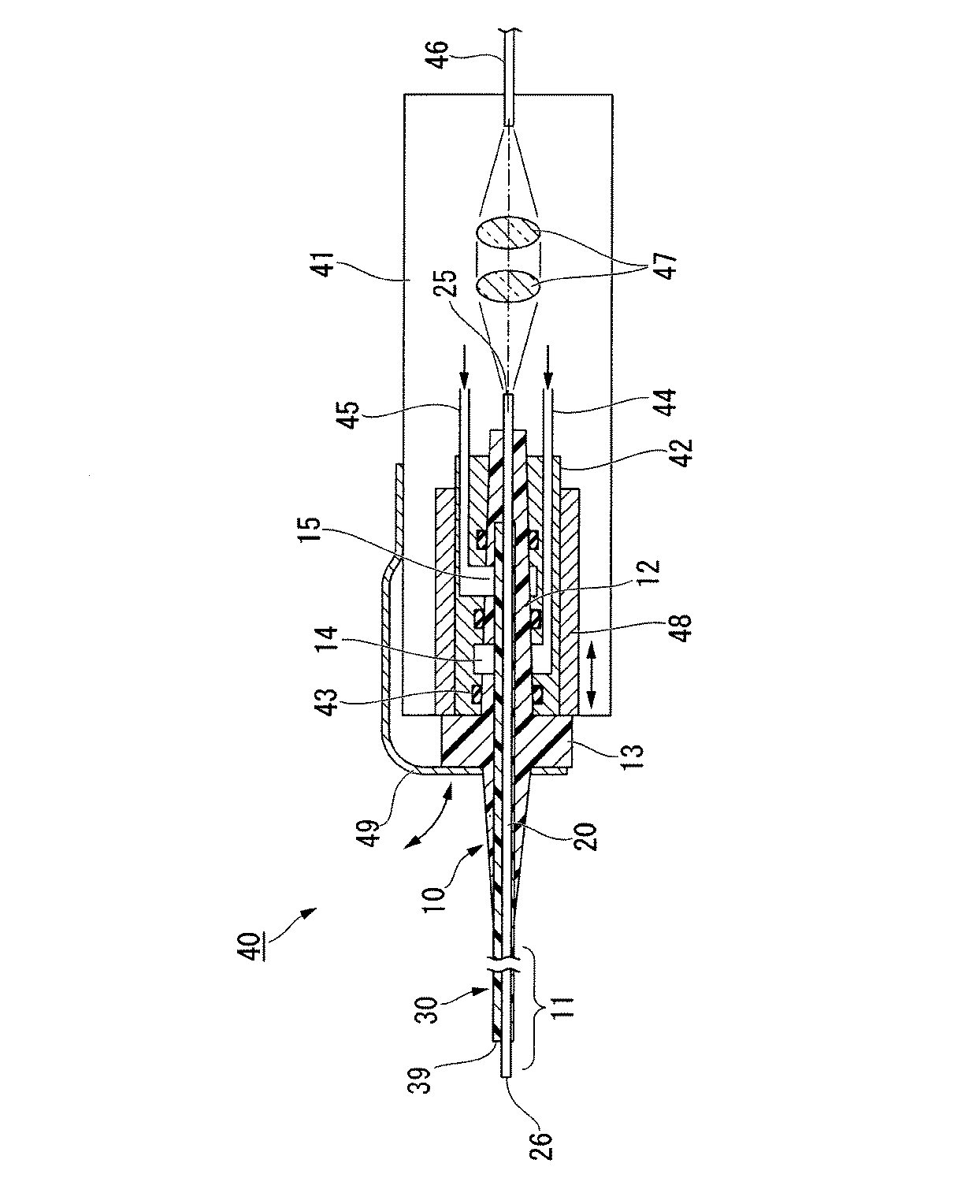
図3に、レーザハンドピースの構成例を示す。ここで例示するハンドピース40は、術者(特に歯科医)が手に持って操作できるように構成されており、歯科用プローブ10は、ハンドピース本体41の先端側に設けられたレセプタクル42に対して着脱可能に装着されている。レセプタクル42は、例えばスプリング43等でプローブ本体部12の外周面をその中心軸に向かう方向に押圧し、光軸の位置を安定させる。また、ファスナ49をプローブ本体部12の外面に突出形成されたフランジ部13に係合させることにより、使用時に歯科用プローブ10が意図せず脱落することを防止することができる。歯科用プローブ10をハンドピース本体41から取り外すときには、ファスナ49を上げ、図示しない操作手段を介してエジェクタ48をハンドピース本体41の先端側(図3の左側)に移動させ、歯科用プローブ10をレセプタクル42から押し出す。
The
FIG. 3 shows a configuration example of the laser handpiece. The
ハンドピース本体41には、給水管44および給気管45が設けられている。給水管44および給気管45は、図示しない水およびエアの供給装置に接続されている。
給水管44はプローブ本体部12の切欠14に設けられた水導入口37(図2参照)に接続されている。また、給気管45は切欠15に設けられたエア導入口38(図2参照)に接続されている。
The
The
ハンドピース本体41の後端側には、レーザ光を供給するためレーザ光源に接続された光ファイバ46が保持されている。光源側の光ファイバ46と、プローブ10の光ファイバ20とは、コリメートレンズ47等を介して非接触で光結合されている。このため、光ファイバ20,46の端面同士を突き合わせて接続する場合に比べて、プローブ10の着脱の際に光ファイバ20,46の端面に外力が加わらず、光ファイバ20,46の端面の損傷を防ぐことができる。
An
歯科治療の際、術者はハンドピース本体41に適宜の先端形状を有するプローブ10を装着してハンドピース40を構成し、患部に水およびエアを供給しながらレーザ光を照射することで、歯牙組織の処置を行うことができる。プローブ先端部11が所望の形状に曲げられていても、光ファイバ20からの漏れ光によるプローブ先端部11の温度上昇が抑制されるので、患者がプローブ先端部11の高熱を感じて不快感を覚えたり、火傷を起こしたりするおそれがない。
At the time of dental treatment, the surgeon attaches the
以下、実施例をもって本発明を具体的に説明する。なお、本発明は、実施例の形状や寸法のみを対象としたものではなく、コア径・クラッド径・ファイバ長さ・曲げ角度・被覆径・金属コート径・チューブ構造などを初めとする形状や寸法、さらに材質などを特に制限するものではない。 Hereinafter, the present invention will be specifically described with reference to examples. The present invention is not intended only for the shapes and dimensions of the examples, but includes shapes such as core diameter, cladding diameter, fiber length, bending angle, coating diameter, metal coating diameter, tube structure, and the like. There are no particular restrictions on dimensions, materials, and the like.
<実施例1>
・図1(c)に示すように、大口径ファイバ(コア径;φ400μm、クラッド径;φ500μm)の外側に厚さ50μmのシリコン樹脂(屈折率;1.35)の樹脂層と、その外側に厚さ50μmの銅をコートした金属コート光ファイバを用いた。前記金属コート光ファイバは、長さが40mmで、中央部に30°の曲げ角度を有した構造となっており、これをマルチルーメン構造のウレタン製チューブに挿入し、モールドにて一体成形したプローブを作製した。
<Example 1>
As shown in FIG. 1 (c), a resin layer of silicon resin (refractive index: 1.35) having a thickness of 50 μm on the outside of a large-diameter fiber (core diameter: φ400 μm, cladding diameter: φ500 μm), and on the outside thereof A metal-coated optical fiber coated with copper having a thickness of 50 μm was used. The metal-coated optical fiber has a length of 40 mm and a structure having a bending angle of 30 ° at the center, and this is inserted into a multi-lumen urethane tube and integrally molded with a mold. Was made.
<実施例2>
・シリコン樹脂に代えて、フッ化アクリル樹脂(屈折率;1.42)を用いたこと以外は実施例1と同じにして、プローブを作製した。
<Example 2>
A probe was manufactured in the same manner as in Example 1 except that a fluorinated acrylic resin (refractive index; 1.42) was used instead of the silicon resin.
<実施例3>
・シリコン樹脂に代えて、酢酸ビニル樹脂(屈折率;1.46)を用いたこと以外は実施例1と同じにして、プローブを作製した。
<Example 3>
A probe was produced in the same manner as in Example 1 except that vinyl acetate resin (refractive index; 1.46) was used instead of silicon resin.
<比較例1>
・シリコン樹脂に代えて、ポリメタクリル酸メチル(屈折率;1.49)を用いたこと以外は実施例1と同じにして、プローブを作製した。
<Comparative Example 1>
A probe was produced in the same manner as in Example 1 except that polymethyl methacrylate (refractive index; 1.49) was used instead of silicon resin.
<比較例2>
・シリコン樹脂に代えて、ポリイミド樹脂(屈折率;1.52)を用いたこと以外は実施例1と同じにして、プローブを作製した。
<Comparative example 2>
A probe was manufactured in the same manner as in Example 1 except that polyimide resin (refractive index; 1.52) was used instead of silicon resin.
<比較例3>
・シリコン樹脂に代えて、ポリカーボネート樹脂(屈折率;1.59)を用いたこと以外は実施例1と同じにして、プローブを作製した。
<Comparative Example 3>
A probe was manufactured in the same manner as in Example 1 except that polycarbonate resin (refractive index: 1.59) was used instead of silicon resin.
<試験例>
・実施例と比較例の試料(n=10)について、エルビウム・YAGレーザを用いて、出力;350mJ、繰返し速度10ppsにて、10秒間連続照射した。そして30°の曲げを有したプローブの中央部を市販の接触式温時計にて連続照射直後(10秒後)の温度を測定した。試験は室温(23℃)で実施した。
<Test example>
-Samples of Examples and Comparative Examples (n = 10) were irradiated continuously for 10 seconds at an output of 350 mJ and a repetition rate of 10 pps using an erbium YAG laser. And the temperature immediately after continuous irradiation (after 10 seconds) was measured for the central part of the probe having a 30 ° bend with a commercially available contact-type timepiece. The test was performed at room temperature (23 ° C.).
<試験結果>
・試験結果を表1に示す。表中の測定温度は、n=10の平均値である。
<Test results>
-Test results are shown in Table 1. The measured temperature in the table is an average value of n = 10.
<考察>
表1に示す試験結果からわかるように、樹脂被覆層の屈折率がクラッド(純粋石英ガラス)の屈折率より大きいもの(比較例1〜3)は、曲げ加工されている箇所でレーザ光が漏れ光となって金属コート層側に拡散されているものと考えられる。逆に、樹脂被覆層の屈折率がクラッドの屈折率より小さいもの(実施例1〜3)は、曲げ加工されている箇所でレーザ光が漏れ光とならず、金属コート層側への拡散が制限されているものと考えられる。
<Discussion>
As can be seen from the test results shown in Table 1, in the case where the refractive index of the resin coating layer is larger than the refractive index of the clad (pure quartz glass) (Comparative Examples 1 to 3), the laser beam leaks at the bent portion. It is considered that light is diffused to the metal coat layer side. On the contrary, in the case where the refractive index of the resin coating layer is smaller than the refractive index of the cladding (Examples 1 to 3), the laser beam does not leak at the bent portion, and the diffusion to the metal coat layer side does not occur. It is considered restricted.
純粋石英層の屈折率は1.463程度であることが知られている。比較例1ではそれより若干屈折率が高いため、数度の温度上昇が確認されているので好ましくないことは明らかである。 It is known that the refractive index of a pure quartz layer is about 1.463. In Comparative Example 1, since the refractive index is slightly higher than that, it is clear that a temperature increase of several degrees has been confirmed, which is not preferable.
実施例3は、純粋石英層の屈折率と同レベルであって、それほどの温度上昇は確認されていない。しかしながら、角度を30°以上に曲げた場合や、もっとハイパワーで長時間のレーザ照射を想定すると、温度上昇のマージンが少ないように思われる。 Example 3 is at the same level as the refractive index of the pure quartz layer, and so much temperature rise has not been confirmed. However, it seems that there is little margin for temperature rise when the angle is bent to 30 ° or more or when laser irradiation with higher power and longer time is assumed.
以上より、本発明の歯科用プローブで用いる樹脂被覆層の屈折率は、純粋石英層の屈折率よりも小さいこと、好ましくは純粋石英層の屈折率よりも、0.04以上小さい屈折率であるほうがよいことが判明した。
また、漏れ光の有無は、光ファイバのクラッドとその外側の樹脂被覆層との屈折率差によるものであるから、クラッドの材質が純粋石英層でない場合も同様に、樹脂被覆層の屈折率がクラッドの屈折率より小さくすることにより、温度上昇を抑制することができる。
From the above, the refractive index of the resin coating layer used in the dental probe of the present invention is smaller than the refractive index of the pure quartz layer, preferably 0.04 or more smaller than the refractive index of the pure quartz layer. It turned out to be better.
In addition, since the presence or absence of leakage light is due to the difference in refractive index between the cladding of the optical fiber and the resin coating layer outside the optical fiber, the refractive index of the resin coating layer is also the same when the cladding material is not a pure quartz layer. By making it smaller than the refractive index of the cladding, the temperature rise can be suppressed.
10…歯科用プローブ、11…プローブ先端部、20…光ファイバ、21…コア、22…クラッド、23…樹脂被覆層、24…金属被覆層、30…マルチルーメンチューブ、31…水の流路、32…エアの流路、33…管路、40…レーザハンドピース。
DESCRIPTION OF
Claims (4)
水の流路と、エアの流路と、光ファイバが挿通される管路がそれぞれ互いに離隔されて貫通穴として内部に形成された可とう性を有する高分子化合物からなるマルチルーメンチューブと、
クラッドの外周上に設けられた樹脂被覆層、および前記樹脂被覆層の外周上に設けられた金属被覆層を有する光ファイバであって、その金属被覆層が前記光ファイバの曲げ変形に対応して変形可能であるとともに、曲げ変形された前記光ファイバの形状を保持可能であり、その樹脂被覆層における屈折率が前記クラッドより低い光ファイバと
を用意し、
前記マルチルーメンチューブの管路に前記光ファイバを挿通してプローブ先端部を構成し、
前記水の流路および前記エアの流路内に着脱可能な補強材を充填し、前記光ファイバおよび前記マルチルーメンチューブの周囲に溶融樹脂を供給して固化させることにより、前記光ファイバの外面形状を型として、光ファイバ通路を有するプローブ本体部を前記マルチルーメンチューブと一体にインサート成形することを特徴とする歯科用プローブの製造方法。 In a dental treatment laser handpiece, a method for manufacturing a dental probe used for guiding laser light transmitted through an optical fiber to an irradiated position,
A water passage, an air passage, and a multi-lumen tube made of a polymer compound having flexibility and formed as through holes in which pipes through which optical fibers are inserted are separated from each other;
An optical fiber having a resin coating layer provided on the outer periphery of the clad and a metal coating layer provided on the outer periphery of the resin coating layer, the metal coating layer corresponding to bending deformation of the optical fiber An optical fiber that is deformable and can retain the shape of the bent optical fiber, and has a refractive index in the resin coating layer lower than that of the clad,
The probe tip is constructed by inserting the optical fiber through the multi-lumen tube line ,
The outer surface shape of the optical fiber is filled with a removable reinforcing material in the water flow channel and the air flow channel, and a molten resin is supplied and solidified around the optical fiber and the multi-lumen tube. A method of manufacturing a dental probe, wherein a probe main body portion having an optical fiber passage is insert-molded integrally with the multi-lumen tube, using a mold as a mold .
前記マルチルーメンチューブにおける前記水の流路および前記エアの流路のそれぞれの後端が前記プローブ本体部内において閉塞され、
前記プローブ本体部の側面に設けた2つの切り欠きのそれぞれの内部において、前記マルチルーメンチューブが露出され、その露出部それぞれに前記水の流路又は前記エアの流路についての導入口が設けられていることを特徴とする請求項1に記載の歯科用プローブの製造方法。 The probe main body, Ri Do from the multi-lumen polymeric compound on the rear end outer periphery is molded integrally with the multi-lumen tube of the tube,
The rear ends of the water flow path and the air flow path in the multi-lumen tube are closed in the probe main body,
The multi-lumen tube is exposed inside each of the two notches provided on the side surface of the probe main body, and an inlet for the water channel or the air channel is provided in each exposed portion. The method for manufacturing a dental probe according to claim 1, wherein:
Priority Applications (5)
| Application Number | Priority Date | Filing Date | Title |
|---|---|---|---|
| JP2009052093A JP5507096B2 (en) | 2009-03-05 | 2009-03-05 | Manufacturing method of dental probe |
| EP10748518.7A EP2392287B1 (en) | 2009-03-05 | 2010-03-03 | Dental probe |
| CN2010800096466A CN102333495A (en) | 2009-03-05 | 2010-03-03 | The dental probe |
| PCT/JP2010/001464 WO2010100919A1 (en) | 2009-03-05 | 2010-03-03 | Dental probe |
| US13/225,082 US20110318701A1 (en) | 2009-03-05 | 2011-09-02 | Dental probe |
Applications Claiming Priority (1)
| Application Number | Priority Date | Filing Date | Title |
|---|---|---|---|
| JP2009052093A JP5507096B2 (en) | 2009-03-05 | 2009-03-05 | Manufacturing method of dental probe |
Publications (2)
| Publication Number | Publication Date |
|---|---|
| JP2010201068A JP2010201068A (en) | 2010-09-16 |
| JP5507096B2 true JP5507096B2 (en) | 2014-05-28 |
Family
ID=42709485
Family Applications (1)
| Application Number | Title | Priority Date | Filing Date |
|---|---|---|---|
| JP2009052093A Active JP5507096B2 (en) | 2009-03-05 | 2009-03-05 | Manufacturing method of dental probe |
Country Status (5)
| Country | Link |
|---|---|
| US (1) | US20110318701A1 (en) |
| EP (1) | EP2392287B1 (en) |
| JP (1) | JP5507096B2 (en) |
| CN (1) | CN102333495A (en) |
| WO (1) | WO2010100919A1 (en) |
Families Citing this family (10)
| Publication number | Priority date | Publication date | Assignee | Title |
|---|---|---|---|---|
| CN102488565B (en) * | 2011-11-18 | 2013-12-25 | 南京春辉科技实业有限公司 | Rigid special-shaped micro-structural fiber rod used in dentistry |
| US10470820B2 (en) * | 2015-09-23 | 2019-11-12 | Jeffrey W. Zerfas | Laser optical fiber for endoscopic surgical procedures having a re-coated elongated tip with visual burn-back indicator and an improved self-aligning stability sheath |
| CN106214275B (en) * | 2016-09-22 | 2017-07-04 | 李博 | Dentistry therapy instrument |
| EP3706655B1 (en) * | 2017-11-10 | 2024-07-24 | Boston Scientific Scimed, Inc. | Medical laser fiber |
| CN111479535B (en) * | 2017-12-12 | 2023-03-14 | 爱尔康公司 | Multi-core optical fiber for multi-point laser probe |
| JP6990255B2 (en) * | 2018-12-26 | 2022-02-03 | 桂林市啄木鳥医療器械有限公司 | Optical path switching structure used for the handle of the oral laser treatment device |
| CN110292720B (en) * | 2019-06-11 | 2021-03-02 | 中南大学湘雅二医院 | An ERCP-based light irradiation device for photodynamic therapy |
| CN110559091B (en) * | 2019-09-29 | 2021-02-02 | 中国人民解放军陆军军医大学第一附属医院 | Dental handpiece with auxiliary distance measuring and depth fixing functions |
| JP2021065257A (en) * | 2019-10-17 | 2021-04-30 | 朝日インテック株式会社 | Light irradiation device and light irradiation system |
| US11719878B2 (en) * | 2019-10-30 | 2023-08-08 | Sterlite Technologies Limited | Ultra reduced diameter optical fibre |
Family Cites Families (21)
| Publication number | Priority date | Publication date | Assignee | Title |
|---|---|---|---|---|
| JPS5520562B2 (en) * | 1973-06-13 | 1980-06-03 | ||
| JPS54103098U (en) * | 1977-12-29 | 1979-07-20 | ||
| DE2907650C3 (en) * | 1979-02-27 | 1981-08-13 | Heraeus Quarzschmelze Gmbh, 6450 Hanau | Multimode light guide |
| US4776659A (en) * | 1985-11-21 | 1988-10-11 | Mruk Walter S | Optical coupler integrated with light emitter and detector units |
| JP2535250B2 (en) * | 1990-09-06 | 1996-09-18 | 三菱電線工業株式会社 | Catheter |
| US5312396A (en) * | 1990-09-06 | 1994-05-17 | Massachusetts Institute Of Technology | Pulsed laser system for the surgical removal of tissue |
| JP3124643B2 (en) * | 1991-11-27 | 2001-01-15 | 株式会社モリタ製作所 | Laser handpiece for dental treatment |
| JPH06258531A (en) * | 1993-03-09 | 1994-09-16 | Totoku Electric Co Ltd | Optical fiber and method of manufacturing optical fiber bundle using the same |
| JP3000840B2 (en) * | 1993-12-24 | 2000-01-17 | 住友電装株式会社 | Temperature detector |
| JP3638191B2 (en) * | 1997-01-31 | 2005-04-13 | 信司 國分 | Medical laser handpiece |
| US6027473A (en) * | 1997-09-05 | 2000-02-22 | Cordis Webster, Inc. | Handle for steerable DMR catheter |
| WO1999039652A1 (en) * | 1998-02-06 | 1999-08-12 | Eigil Moelsgaard | A dental system for treatment of periodontal pockets laser light |
| US6224543B1 (en) * | 1998-05-21 | 2001-05-01 | Adroit Medical Systems, Inc. | Non-latex inverted sheath device |
| DE19942470B4 (en) * | 1998-09-08 | 2013-04-11 | Fujitsu Ltd. | Optical semiconductor module and method for manufacturing an optical semiconductor module |
| CN1095549C (en) * | 1999-09-30 | 2002-12-04 | 中国科学院上海光学精密机械研究所 | Coupling device of laser diode and optical fiber |
| JP2004236949A (en) * | 2003-02-07 | 2004-08-26 | Olympus Corp | Energy irradiation apparatus |
| JP2008141066A (en) * | 2006-12-04 | 2008-06-19 | Hitachi Cable Ltd | Optical fiber for fiber laser device and fiber laser device |
| JP2008292660A (en) * | 2007-05-23 | 2008-12-04 | Fujikura Ltd | Optical fiber, optical communication module |
| CN101101353A (en) * | 2007-07-23 | 2008-01-09 | 通鼎集团有限公司 | Sensing optical fiber |
| JP2009052093A (en) | 2007-08-27 | 2009-03-12 | Canon Anelva Corp | Embedded film forming method and apparatus |
| US8017246B2 (en) * | 2007-11-08 | 2011-09-13 | Philips Lumileds Lighting Company, Llc | Silicone resin for protecting a light transmitting surface of an optoelectronic device |
-
2009
- 2009-03-05 JP JP2009052093A patent/JP5507096B2/en active Active
-
2010
- 2010-03-03 WO PCT/JP2010/001464 patent/WO2010100919A1/en not_active Ceased
- 2010-03-03 EP EP10748518.7A patent/EP2392287B1/en active Active
- 2010-03-03 CN CN2010800096466A patent/CN102333495A/en active Pending
-
2011
- 2011-09-02 US US13/225,082 patent/US20110318701A1/en not_active Abandoned
Also Published As
| Publication number | Publication date |
|---|---|
| EP2392287B1 (en) | 2020-12-09 |
| JP2010201068A (en) | 2010-09-16 |
| EP2392287A1 (en) | 2011-12-07 |
| EP2392287A4 (en) | 2017-10-18 |
| US20110318701A1 (en) | 2011-12-29 |
| WO2010100919A1 (en) | 2010-09-10 |
| CN102333495A (en) | 2012-01-25 |
Similar Documents
| Publication | Publication Date | Title |
|---|---|---|
| JP5507096B2 (en) | Manufacturing method of dental probe | |
| US12251273B2 (en) | Illuminated suction apparatus | |
| US6129721A (en) | Medical laser treatment device and laser probe for the same | |
| CN101385633B (en) | Male urethra dilator with endoscope | |
| US5921916A (en) | Endoscope utilizing a fiber optic holding tube with a jacket slit for lateral placement of the fiber optic | |
| US4519390A (en) | Fiber optic laser catheter | |
| JP7337533B2 (en) | medical light guide | |
| JP5360650B2 (en) | Lacrimal tract treatment device | |
| JPH0928715A (en) | Laser probe and laser medical device using the same | |
| CN101385634B (en) | Diameter variable male urethra dilator with endoscope | |
| JPH07163593A (en) | Photoirradiating device | |
| CN201350091Y (en) | Laser scalpel with replaceable optical fiber needle | |
| JP2026503099A (en) | Sheath placement device and method of use | |
| CN108294722A (en) | Electronics angioscope | |
| JP6181535B2 (en) | Laser handpiece and laser treatment apparatus | |
| JPWO2016158351A1 (en) | Optical unit and endoscope | |
| JP3540427B2 (en) | Endoscope, fiber assembly for endoscope, and manufacturing method thereof | |
| JPH0712363B2 (en) | Special laser chip | |
| CN205516038U (en) | Optics therapeutic instrument of canalis radicis dentis | |
| CN219148012U (en) | Handle for oral cavity laser medical equipment | |
| WO2009129119A2 (en) | Fiberscopes and fiber bundles | |
| JP2014217513A (en) | Laser irradiation chip and fiber module used therefor | |
| WO2025065002A1 (en) | Laser disinfection and/or sterilization device and nanostructured light guide | |
| JPH0751286A (en) | Laser therapy equipment | |
| JPH02114930A (en) | Insertion assist jig for endoscope |
Legal Events
| Date | Code | Title | Description |
|---|---|---|---|
| A621 | Written request for application examination |
Free format text: JAPANESE INTERMEDIATE CODE: A621 Effective date: 20111202 |
|
| A131 | Notification of reasons for refusal |
Free format text: JAPANESE INTERMEDIATE CODE: A131 Effective date: 20130409 |
|
| A131 | Notification of reasons for refusal |
Free format text: JAPANESE INTERMEDIATE CODE: A131 Effective date: 20131001 |
|
| A521 | Request for written amendment filed |
Free format text: JAPANESE INTERMEDIATE CODE: A523 Effective date: 20131122 |
|
| TRDD | Decision of grant or rejection written | ||
| A01 | Written decision to grant a patent or to grant a registration (utility model) |
Free format text: JAPANESE INTERMEDIATE CODE: A01 Effective date: 20140218 |
|
| A61 | First payment of annual fees (during grant procedure) |
Free format text: JAPANESE INTERMEDIATE CODE: A61 Effective date: 20140319 |
|
| R151 | Written notification of patent or utility model registration |
Ref document number: 5507096 Country of ref document: JP Free format text: JAPANESE INTERMEDIATE CODE: R151 |
|
| R250 | Receipt of annual fees |
Free format text: JAPANESE INTERMEDIATE CODE: R250 |
|
| R250 | Receipt of annual fees |
Free format text: JAPANESE INTERMEDIATE CODE: R250 |
|
| R250 | Receipt of annual fees |
Free format text: JAPANESE INTERMEDIATE CODE: R250 |
|
| R250 | Receipt of annual fees |
Free format text: JAPANESE INTERMEDIATE CODE: R250 |
|
| R250 | Receipt of annual fees |
Free format text: JAPANESE INTERMEDIATE CODE: R250 |
|
| R250 | Receipt of annual fees |
Free format text: JAPANESE INTERMEDIATE CODE: R250 |
|
| R250 | Receipt of annual fees |
Free format text: JAPANESE INTERMEDIATE CODE: R250 |
|
| R250 | Receipt of annual fees |
Free format text: JAPANESE INTERMEDIATE CODE: R250 |
|
| R250 | Receipt of annual fees |
Free format text: JAPANESE INTERMEDIATE CODE: R250 |