JP5476351B2 - Cap unit for puncture repair - Google Patents
Cap unit for puncture repair Download PDFInfo
- Publication number
- JP5476351B2 JP5476351B2 JP2011213077A JP2011213077A JP5476351B2 JP 5476351 B2 JP5476351 B2 JP 5476351B2 JP 2011213077 A JP2011213077 A JP 2011213077A JP 2011213077 A JP2011213077 A JP 2011213077A JP 5476351 B2 JP5476351 B2 JP 5476351B2
- Authority
- JP
- Japan
- Prior art keywords
- flow path
- inner lid
- bottle container
- cap unit
- compressed air
- Prior art date
- Legal status (The legal status is an assumption and is not a legal conclusion. Google has not performed a legal analysis and makes no representation as to the accuracy of the status listed.)
- Expired - Fee Related
Links
Images


Classifications
-
- B—PERFORMING OPERATIONS; TRANSPORTING
- B29—WORKING OF PLASTICS; WORKING OF SUBSTANCES IN A PLASTIC STATE IN GENERAL
- B29C—SHAPING OR JOINING OF PLASTICS; SHAPING OF MATERIAL IN A PLASTIC STATE, NOT OTHERWISE PROVIDED FOR; AFTER-TREATMENT OF THE SHAPED PRODUCTS, e.g. REPAIRING
- B29C73/00—Repairing of articles made from plastics or substances in a plastic state, e.g. of articles shaped or produced by using techniques covered by this subclass or subclass B29D
- B29C73/16—Auto-repairing or self-sealing arrangements or agents
- B29C73/166—Devices or methods for introducing sealing compositions into articles
-
- B—PERFORMING OPERATIONS; TRANSPORTING
- B29—WORKING OF PLASTICS; WORKING OF SUBSTANCES IN A PLASTIC STATE IN GENERAL
- B29L—INDEXING SCHEME ASSOCIATED WITH SUBCLASS B29C, RELATING TO PARTICULAR ARTICLES
- B29L2030/00—Pneumatic or solid tyres or parts thereof
Landscapes
- Engineering & Computer Science (AREA)
- Mechanical Engineering (AREA)
- Closures For Containers (AREA)
Description
本発明は、パンク修理剤を収容したボトル容器の口部に取り付けられ、コンプレッサからの圧縮空気により、パンクしたタイヤにパンク修理剤と圧縮空気とを順次注入してパンクを応急的に修理するパンク修理用のキャップユニットに関する。 The present invention relates to a puncture which is attached to a mouth of a bottle container containing a puncture repair agent, and in which puncture repair agent and compressed air are sequentially injected into a punctured tire by compressed air from a compressor to repair the puncture quickly. The present invention relates to a cap unit for repair.
例えば下記の特許文献1には、図8に示すように、ボトル容器aの口部a1に取り付けられ、コンプレッサdからの圧縮空気により、パンクしたタイヤtにパンク修理剤と圧縮空気とを順次注入してパンクを応急的に修理するパンク修理用のキャップユニットbが記載されている。 For example, in Patent Document 1 below, as shown in FIG. 8, a puncture repair agent and compressed air are sequentially injected into a punctured tire t by compressed air from a compressor d, which is attached to a mouth portion a1 of a bottle container a. A puncture repair cap unit b for repairing punctures is described.
このキャップユニットbは、コンプレッサdからの圧縮空気をボトル容器a内に送り込む第1の流路eと、この圧縮空気の送り込みにより前記ボトル容器aからパンク修理剤と圧縮空気とを順次取り出す第2の流路fとを具えるキャップ本体g、及び前記第1、第2の流路e、fを同時に閉じる一つの内蓋hから構成される。 The cap unit b has a first flow path e for sending the compressed air from the compressor d into the bottle container a, and a second flow for sequentially taking out the puncture repair agent and the compressed air from the bottle container a by feeding the compressed air. A cap body g having a flow path f and a single inner lid h that simultaneously closes the first and second flow paths e and f.
具体的には、前記キャップ本体gは、ボトル容器aの口部a1を螺着する取付け凹部g1の底面から立ち上がるボス部g2を具える。このボス部g2は、その外周面によって、前記内蓋hが弾性的に嵌着される内蓋取付部分jを形成するとともに、内蓋取付部分jよりも内側に、前記第1、第2の流路e、fの上開口部e1、f1をそれぞれ開口させている。又前記内蓋hは、前記ボス部g2の外周面(内蓋取付部分j)に嵌着され第1の流路eを閉じる内蓋本体haと、前記上開口部f1に嵌着されて第2の流路fを閉じる栓軸部hbとが一体に形成されている。 Specifically, the cap body g includes a boss portion g2 that rises from the bottom surface of the mounting recess g1 into which the mouth portion a1 of the bottle container a is screwed. The boss portion g2 forms an inner lid mounting portion j to which the inner lid h is elastically fitted by the outer peripheral surface thereof, and the first and second inner sides are more inside than the inner lid mounting portion j. Upper openings e1 and f1 of the flow paths e and f are opened, respectively. The inner lid h is fitted on the outer peripheral surface (inner lid mounting portion j) of the boss portion g2 and closes the first flow path e, and is fitted on the upper opening f1. The plug shaft portion hb that closes the two flow paths f is integrally formed.
そしてキャップユニットbはボトル容器aを装着した装着状態にて車載保管される。そしてパンク修理の際には、この装着状態のキャップユニットbに配管を施してコンプレッサdを作動させる。これにより、圧縮空気が第1の流路eをへて内蓋本体ha内に流れ込み、その内圧上昇によって、前記内蓋hを自動的に取り外し第1、第2の流路e、fを解放させるのである。 The cap unit b is stored on the vehicle in a mounted state in which the bottle container a is mounted. When repairing puncture, piping is applied to the cap unit b in the mounted state to operate the compressor d. As a result, the compressed air flows into the inner lid body ha through the first flow passage e, and the inner lid h is automatically removed and the first and second flow passages e and f are released by the increase in internal pressure. To make it happen.
従って前記内蓋hでは、保管時には外れず、逆にパンク修理時には圧縮空気によって容易に外れることが必要である。そのために、前記内蓋hとキャップ本体gとの間の嵌め合い寸法の精度を高め、内蓋hとキャップ本体gとの間の嵌合力を高精度で管理することが要求される。 Therefore, it is necessary that the inner lid h does not come off at the time of storage and is easily removed by compressed air at the time of puncture repair. For this purpose, it is required to improve the accuracy of the fitting size between the inner lid h and the cap body g and to manage the fitting force between the inner lid h and the cap body g with high accuracy.
しかし従来構造では、前記内蓋本体haと栓軸部hbとの双方に嵌合バラツキが発生する。そのため嵌め合い寸法によりいっそう高い精度が要求され、歩留まり率の低下、及び製品検査工程での行程コストの上昇を招いている。 However, in the conventional structure, fitting variation occurs in both the inner lid main body ha and the plug shaft portion hb. For this reason, higher precision is required depending on the fitting size, resulting in a decrease in yield rate and an increase in process cost in the product inspection process.
しかも従来構造では、前記内蓋本体haの嵌合、及び栓軸部hbの嵌合が同時に外れることが必要であり、例えば栓軸部hbが先に外れかかって隙間が生じた場合、内蓋本体ha内の圧縮空気がその隙間から第2の流路fに流出するため、内蓋本体haの内圧が上昇しなくなる。逆に、内蓋本体haが先に外れかかって隙間が生じた場合には、その隙間から圧縮空気がボトル容器a内に漏れ出してボトル容器a内の圧力が上昇するため、内蓋本体haの内外の圧力差が減少する。その結果、何れの場合も内蓋hがボス部g2から外れなくなる。このように、内蓋本体haと栓軸部hbとが同時に外れることが必要であり、このことも高精度が必要な要因となっている。 In addition, in the conventional structure, it is necessary that the fitting of the inner lid body ha and the fitting of the plug shaft portion hb be simultaneously released. For example, when the plug shaft portion hb is first removed and a gap is generated, Since the compressed air in the main body ha flows out from the gap into the second flow path f, the internal pressure of the inner lid main body ha does not increase. On the contrary, when the inner lid body ha comes off first and a gap is formed, compressed air leaks into the bottle container a from the gap and the pressure in the bottle container a rises. The pressure difference between inside and outside decreases. As a result, in any case, the inner lid h does not come off from the boss part g2. Thus, it is necessary for the inner lid body ha and the plug shaft portion hb to be detached at the same time, which is also a factor that requires high accuracy.
そこで本発明は、前記内蓋取付部分よりも外側に第2の流路の上開口部を開口させ、前記第1の流路を閉じる内蓋とは独立した別の内蓋によって、前記第2の流路を閉止することを基本として、内蓋の取り外しを確実化しながら、内蓋とキャップ本体との嵌め合い精度を緩和でき、キャップユニットの歩留まり率の低下、及び製品検査工程の行程コストの上昇などを抑えうるパンク修理用のキャップユニットを提供することを目的としている。 Therefore, the present invention provides a second inner lid that is independent of the inner lid that opens the upper opening of the second flow path outside the inner lid mounting portion and closes the first flow path. As a basic rule, it is possible to ease the fitting accuracy between the inner lid and the cap body while ensuring the removal of the inner lid, and to reduce the yield rate of the cap unit and the process cost of the product inspection process. The purpose is to provide a cap unit for puncture repair that can suppress the rise.
上記課題を解決するために、本願請求項1の発明は、パンク修理剤を収容したボトル容器の口部に取り付くとともに、コンプレッサからの圧縮空気を前記ボトル容器内に送り込む第1の流路、及びこの圧縮空気の送り込みにより前記ボトル容器からパンク修理剤と圧縮空気とを順次取り出す第2の流路を有するキャップ本体、
並びに前記第1、第2の流路を閉じる閉止手段を具えたキャップユニットであって、
前記閉止手段は、前記第1の流路を閉じる第1の内蓋と、この第1の内蓋とは独立して形成されかつ前記第2の流路を閉じる第2の内蓋とからなるとともに、
前記キャップ本体は、前記ボトル容器の口部を挿入して固定する口部取付け凹部と、この口部取付け凹部の底面から立上がりかつ前記第1の内蓋が弾性的に嵌着される第1の内蓋取付部分を設けたボス部とを有し、
しかも該ボス部の前記第1の内蓋取付部分よりも内側に、前記第1の流路の上開口部を開口させ、かつ前記第1の内蓋取付部分よりも外側に、前記第2の流路の上開口部を開口させたことを特徴としている。
In order to solve the above problems, the invention of claim 1 of the present application is attached to the mouth of a bottle container containing a puncture repair agent, and has a first flow path for sending compressed air from a compressor into the bottle container, and A cap body having a second flow path for sequentially taking out the puncture repair agent and the compressed air from the bottle container by the feeding of the compressed air;
And a cap unit comprising closing means for closing the first and second flow paths,
The closing means includes a first inner lid that closes the first flow path, and a second inner lid that is formed independently of the first inner lid and closes the second flow path. With
The cap body has a mouth mounting recess for inserting and fixing the mouth of the bottle container, a first rising from a bottom surface of the mouth mounting recess and the first inner lid being elastically fitted. A boss portion provided with an inner lid mounting portion,
Moreover, the upper opening of the first flow path is opened inside the first inner lid mounting portion of the boss portion, and the second opening is formed outside the first inner lid mounting portion. The upper opening of the flow path is opened.
また請求項2では、前記第1の流路の上開口部は、キャップユニットに前記ボトル容器が装着された装着状態において、ボトル容器内に収容されたパンク修理剤の液面よりも上方に位置することを特徴としている。 According to a second aspect of the present invention, the upper opening of the first flow path is positioned above the liquid level of the puncture repair agent accommodated in the bottle container when the bottle container is mounted on the cap unit. It is characterized by doing.
また請求項3では、前記第2の流路の上開口部は、前記口部の上端よりも下方に位置することを特徴としている。 According to a third aspect of the present invention, the upper opening of the second flow path is located below the upper end of the mouth.
また請求項4では、前記閉止手段は、コンプレッサからの圧縮空気により第1の流路の圧力が上昇することによって前記第1の内蓋が外れて第1の流路を開くとともに、その後、この第1の流路から流入する圧縮空気によりボトル容器の圧力が上昇することによって前記第2の内蓋が外れて第2の流路を開くことを特徴としている。 According to a fourth aspect of the present invention, the closing means opens the first flow path by removing the first inner lid when the pressure of the first flow path rises due to the compressed air from the compressor. The second inner lid is removed by opening the second flow path when the pressure of the bottle container is increased by the compressed air flowing in from the first flow path.
本発明は叙上の如く、ボス部に設けた第1の内蓋取付部分よりも内側に、第1の流路の上開口部を開口させ、前記第1の内蓋取付部分に第1の内蓋を嵌着することで、第1の流路を閉止している。又第1の内蓋取付部分よりも外側に、第2の流路の上開口部を開口させ、この第2の流路を前記第1の内蓋とは独立した別の第2の内蓋によって閉止している。従って、コンプレッサからの圧縮空気による第1の流路の圧力上昇によって、まず第1の内蓋のみを取り外すことができる。 As described above, according to the present invention, the upper opening of the first flow path is opened inside the first inner lid mounting portion provided in the boss portion, and the first inner lid mounting portion has a first opening. By fitting the inner lid, the first flow path is closed. Further, an upper opening of the second flow path is opened outside the first inner cover mounting portion, and the second flow path is separated from the first inner cover by another second inner cover. It is closed by. Therefore, only the first inner lid can be removed first by the pressure increase in the first flow path by the compressed air from the compressor.
又第1の内蓋が外れることにより、前記第1の流路から流入する圧縮空気によりボトル容器の圧力が上昇する。そのため、このボトル容器の圧力上昇を利用することで、第2の内蓋も順次取り外すことが可能となる。 Further, when the first inner lid is removed, the pressure of the bottle container is increased by the compressed air flowing from the first flow path. Therefore, the second inner lid can also be removed sequentially by using the pressure increase of the bottle container.
このように第1、第2の内蓋を別々に設けているため、それぞれの嵌め合い精度を緩和でき、キャップユニットの歩留まり率の低下、及び製品検査工程の行程コストの上昇などを抑えながら、保管時に内蓋が外れて液漏れが生じるのを確実に防止しうる。又使用時に内蓋が外れなくなってパンク修理作業が行えなくなるのを確実に防止することも可能となる。 Since the first and second inner lids are provided separately in this way, each fitting accuracy can be relaxed, while suppressing a decrease in the yield rate of the cap unit and an increase in the process cost of the product inspection process, It is possible to reliably prevent the liquid from leaking when the inner lid is removed during storage. In addition, it is possible to reliably prevent the puncture repair work from being impossible because the inner lid cannot be removed during use.
以下、本発明の実施の形態について、詳細に説明する。
図1は、本発明のキャップユニット1に、ボトル容器4が装着された装着状態Yを示す断面図であって、前記キャップユニット1は、コンプレッサ3からの圧縮空気を前記ボトル容器4内に送り込む第1の流路5、及びこの圧縮空気の送り込みにより前記ボトル容器4からパンク修理剤Tと圧縮空気とを順次取り出す第2の流路6を有するキャップ本体7、並びに前記第1、第2の流路5、6を閉じる閉止手段8を具える。
Hereinafter, embodiments of the present invention will be described in detail.
FIG. 1 is a cross-sectional view showing a mounting state Y in which a
そして前記閉止手段8は、前記第1の流路5を閉じる第1の内蓋8Aと、この第1の内蓋8Aとは独立して形成されかつ前記第2の流路6を閉じる第2の内蓋8Bとから形成される。
The closing means 8 includes a first
なお前記ボトル容器4は、パンク修理剤Tを収容する容器部4Bの下端に、パンク修理剤Tを取り出す小径円筒状の口部4Aを突出させた周知構造をなす。
The
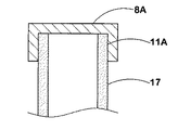
又前記キャップ本体7は、前記ボトル容器4の口部4Aを挿入して固定する口部取付け凹部10と、この口部取付け凹部10の底面10Sから立上がるボス部11とを具える。このボス部11には、前記第1の内蓋8Aが弾性的に嵌着される第1の内蓋取付部分11Aが形成される。そしてこの第1の内蓋取付部分11Aよりも内側に、前記第1の流路5の上開口部5aが開口し、かつ前記第1の内蓋取付部分11Aよりも外側に、前記第2の流路6の上開口部6aが開口している。
The
具体的には、図2に拡大して示すように、本例のキャップ本体7は、上端部に前記口部取付け凹部10を凹設した第1のキャップ本体部7Aと、この第1のキャップ本体部7Aに連結されかつ前記ボス部11の一部を構成する第2のキャップ本体部7Bとから構成される。
Specifically, as shown in an enlarged view in FIG. 2, the
前記第1のキャップ本体部7Aは、前記口部取付け凹部10の底面10Sに、前記口部取付け凹部10とは同心をなす基管部12を突出している。なお前記口部取付け凹部10はその内壁面に内ネジ部を有し、この内ネジ部によって前記口部4Aを螺着する。
The first
又前記第1のキャップ本体部7Aの側部には、コンプレッサ接続用のコンプレッサ接続部13と、タイヤ接続用のタイヤ接続部14とが設けられる。本例では、前記コンプレッサ接続部13及びタイヤ接続部14が、ホース接続部30として形成され、それぞれホース31を介して前記コンプレッサ3及びタイヤtに接続される場合が例示される。
A
又前記第1のキャップ本体部7Aの内部には、前記コンプレッサ接続部13の先端で一端15bが開口しかつ他端15aが基管部12の上端で開口する孔部15、及び前記タイヤ接続部14の先端で一端16bが開口しかつ他端16aが前記底面10Sで開口する孔部16がそれぞれ形成される。
Further, inside the first cap
又前記第2のキャップ本体部7Bは、図2、3に示すように、前記基管部12に下端部が接続される内管部17と、この内管部17の半径方向外側に間隔を隔てて同心に配される外管部18とを具える。この内管部17と外管部18とは、前記内管部17から半径方向外側に放射状にのびる複数の連結リブ19Aからなる連結部19によって一体に接合される。
As shown in FIGS. 2 and 3, the second cap
又前記外管部18の下端には、前記底面10S上に載置保持されるフランジ状の脚片18Aが形成される。そしてこの脚片18Aが、ボトル容器4の口部4A下端と底面10Sとの間で挟まれることにより、前記第2のキャップ本体部7Bが安定して固定されるとともに、前記外管部18と、内管部17及び基管部12との間に環状の孔部20が形成される。この孔部20は、前記孔部16とは前記他端16aで連通するとともに、孔部20の上端は、前記連結リブ19A間の間隙部19Bによって開口している。従って、本例では、前記孔部20と孔部16とが協働して前記第2の流路6を形成するとともに、前記間隙部19Bにより、第2の流路6の上開口部6aを形成している。
A flange-shaped
そして前記孔部20に、前記第2の内蓋8Bが配される。本例の第2の内蓋8Bは、弾性変形可能な合成樹脂材、及びゴム弾性材などからなるリング状をなし、前記内管部17の外周面及び外管部18の内周面と密に嵌合することにより、前記第2の流路6を閉止しうる。この第2の内蓋8Bは、ボトル容器4内の圧力上昇によって下方に押され、前記内管部17から外れて落下することで前記第2の流路6を開放しうる。なお前記底面10Sには、外れて落下した第2の内蓋8Bが、前記孔部16他端16aの開口を塞がないように保持する突起部21が突設される。
The second
又前記内管部17は、前記基管部12と協働して前記ボス部11を形成する。又前記内管部17の中心孔17Hは、前記孔部15とは前記他端15aで連通し、従って、本例では、前記中心孔17Hと孔部15とが協働して前記第1の流路5を形成するとともに、前記中心孔17Hの上端に、前記第1の流路5の上開口部5aが形成される。
The
又前記内管部17の上端部には、図3に示すように、第1の内蓋8Aが弾性的に嵌着される第1の内蓋取付部分11Aが形成される。
Further, as shown in FIG. 3, a first inner
具体的には、本例では図4に示すように、前記内管部17の上端部には、段差部分22aを介して大径部分22bが連設される。又本例の第1の内蓋8Aは、前記大径部分22bの内周面22bSに弾性的に嵌着される嵌合筒部24aと、その上端を閉じる天板部24bとからなる。即ち本例では、前記大径部分22bの内周面22bSが、前記第1の内蓋取付部分11Aを形成し、第1の内蓋8Aは、この大径部分22bの内孔内に嵌め込まれている。なお前記天板部24bには、前記嵌合筒部24aの外周面よりも半径方向外側に突出し、かつ前記大径部分22b上端と当接することにより位置決めされるストッパ部24b1が形成される。
Specifically, as shown in FIG. 4, in this example, a large-
このような大径部分22bを設けることにより、第1の内蓋8Aにおいて、第1の流路5の内圧を受ける面積を増やすことができ、第1の内蓋8Aに大きな上向きの力を作用させることが可能となる。又第1の内蓋8Aを、大径部分22bの内孔内に嵌め込ませることにより、図4(B)に誇張して示すように、内圧作用時には天板部24bが凸状に湾曲変形し、嵌合筒部24aと大径部分22bの前記内周面22bSと嵌合力が弱まる。その結果、保管時における第1の内蓋8Aの取り付き力を同じとしながら、より小さな圧力にて第1の内蓋8Aを取り外すことが可能となる。しかしながら、要求により図5に示すように、前記内管部17の外周面に外嵌するように第1の内蓋8Aを形成することもできる。なお前記第1の内蓋8Aも、第2の内蓋8Bと同様、弾性変形可能な合成樹脂材、及びゴム弾性材などから形成される。
By providing such a
然して、前記キャップユニット1は、保管状体においては、第1、第2の内蓋8A、8Bにより第1、第2の流路5、6が閉止され、パンク修理剤Tの第1、第2の流路5、6への流出が防止される。そしてパンク修理作業においては、コンプレッサ3からの圧縮空気によって第1の流路5の圧力が上昇し、前記第1の内蓋8Aが外れて第1の流路5を開放する。これにより、第1の流路5から流入する圧縮空気によってボトル容器4の圧力が上昇する。又ボトル容器4の圧力上昇により、第2の内蓋8Bが押し下げられて外れ、これによって第2の流路6が開放され、パンク修理剤Tをタイヤtに充填することができる。
However, in the storage unit, the cap unit 1 has the first and
このように第1、第2の内蓋8A、8Bを別々に設け、圧縮空気によって順番に取り外すため、保管時の液漏れ、及び使用時に内蓋が外れなくなることによる動作不良等を防止しながら、各内蓋8A、8Bの嵌め合い精度を緩和させることが可能となる。
Thus, since the first and second
なお前記第1の流路5の上開口部5aは、図1に示すように、前記装着状態Yにおけるパンク修理剤Tの液面TSよりも上方に位置させることが好ましい。その理由としては、もし第2の流路6側が塞がれた状態でコンプレッサ3を作動してしまった場合、ボトル容器4内の圧力が異常に高まり、コンプレッサ3に脈動がある場合には、ボトル容器4のパンク修理剤Tがコンプレッサ3側に逆流する恐れが生じる。従って、前記上開口部5aを液面TSよりも上方に位置されることで、前記トラブルを防止できる。なお第2の流路6側が塞がれた状態とは、第2の内蓋8Bの不良によって第2の内蓋8Bが外れない場合、前記タイヤ接続部14に接続されるホース31が折れて塞がった場合、或いは、前記ホース31先端がキャップで塞がっている場合などがあり得る。
The
又第2の流路6の上開口部6aは、前記口部4Aの上端よりも下方に位置することが好ましく、これによりパンク修理後にボトル容器4内にパンク修理剤Tが残留するのを防止しうる。
The
又本例では、前記キャップユニット1がホース31を介してコンプレッサ3と接続される場合が例示されるが、図6、7に示すように、キャップユニット1とコンプレッサ3とをホースを介することなく直接接続させることもできる。これにより設置の安定性が増し、パンク修理作業中のボトル容器4の転倒を防止できる。
Further, in this example, the case where the cap unit 1 is connected to the
この場合、前記コンプレッサ接続部13とコンプレッサ3側のキャップ接続部25との一方を、他方に向かって突出する接続ノズル36とし、かつ他方を、前記接続ノズル36が挿入されて該接続ノズル36と密に接続されるノズル受け37として形成する。本例では、前記前記コンプレッサ接続部13が接続ノズル36として形成され、かつキャップ接続部25がノズル受け37として形成される場合が示される。
In this case, one of the
前記接続ノズル36は、外径一定のノズル本体36Aの前端側に、先細コーン状のテーパ面部36Bを具える。なおノズル本体36Aには、Oリングなどである例えば2本のシールリング38が装着される。又前記ノズル受け37は、前記シールリング38を介してノズル本体36Aに気密に嵌合する嵌合孔部37Aの後端に、前記テーパ面部36Bとほぼ同傾斜をなすテーパ面部37Bを具える。このテーパ面部36B、37Bにより、接続ノズル36とノズル受け37とは、同心に位置合わせされる。
The
以上、本発明の特に好ましい実施形態について詳述したが、本発明は図示の実施形態に限定されることなく、種々の態様に変形して実施しうる。 As mentioned above, although especially preferable embodiment of this invention was explained in full detail, this invention is not limited to embodiment of illustration, It can deform | transform and implement in a various aspect.
1 キャップユニット
3 コンプレッサ
4 ボトル容器
4A 口部
5 第1の流路
5a 上開口部
6 第2の流路
6a 上開口部
7 キャップ本体
8 閉止手段
8A 第1の内蓋
8B 第2の流路
10 口部取付け凹部
10S 底面
11 ボス部
11A 第1の内蓋取付部分
T パンク修理剤
DESCRIPTION OF SYMBOLS 1
Claims (4)
並びに前記第1、第2の流路を閉じる閉止手段を具えたキャップユニットであって、
前記閉止手段は、前記第1の流路を閉じる第1の内蓋と、この第1の内蓋とは独立して形成されかつ前記第2の流路を閉じる第2の内蓋とからなるとともに、
前記キャップ本体は、前記ボトル容器の口部を挿入して固定する口部取付け凹部と、この口部取付け凹部の底面から立上がりかつ前記第1の内蓋が弾性的に嵌着される第1の内蓋取付部分を設けたボス部とを有し、
しかも該ボス部の前記第1の内蓋取付部分よりも内側に、前記第1の流路の上開口部を開口させ、かつ前記第1の内蓋取付部分よりも外側に、前記第2の流路の上開口部を開口させたことを特徴とするパンク修理用のキャップユニット。 A first flow path for attaching the compressed air from the compressor into the bottle container, and a puncture repairing agent and compressed air from the bottle container by feeding the compressed air. A cap body having a second flow path for sequentially taking out
And a cap unit comprising closing means for closing the first and second flow paths,
The closing means includes a first inner lid that closes the first flow path, and a second inner lid that is formed independently of the first inner lid and closes the second flow path. With
The cap body has a mouth mounting recess for inserting and fixing the mouth of the bottle container, a first rising from a bottom surface of the mouth mounting recess and the first inner lid being elastically fitted. A boss portion provided with an inner lid mounting portion,
Moreover, the upper opening of the first flow path is opened inside the first inner lid mounting portion of the boss portion, and the second opening is formed outside the first inner lid mounting portion. A cap unit for puncture repair, wherein an upper opening of a flow path is opened.
Priority Applications (5)
| Application Number | Priority Date | Filing Date | Title |
|---|---|---|---|
| JP2011213077A JP5476351B2 (en) | 2011-09-28 | 2011-09-28 | Cap unit for puncture repair |
| CN201280047890.0A CN103842161B (en) | 2011-09-28 | 2012-09-24 | For the cap unit that acanthopore is repaired |
| PCT/JP2012/074361 WO2013047419A1 (en) | 2011-09-28 | 2012-09-24 | Cap unit for puncture repair |
| EP12836291.0A EP2749402A4 (en) | 2011-09-28 | 2012-09-24 | Cap unit for puncture repair |
| US14/345,865 US8978717B2 (en) | 2011-09-28 | 2012-09-24 | Cap unit for puncture repair |
Applications Claiming Priority (1)
| Application Number | Priority Date | Filing Date | Title |
|---|---|---|---|
| JP2011213077A JP5476351B2 (en) | 2011-09-28 | 2011-09-28 | Cap unit for puncture repair |
Publications (2)
| Publication Number | Publication Date |
|---|---|
| JP2013071369A JP2013071369A (en) | 2013-04-22 |
| JP5476351B2 true JP5476351B2 (en) | 2014-04-23 |
Family
ID=47995451
Family Applications (1)
| Application Number | Title | Priority Date | Filing Date |
|---|---|---|---|
| JP2011213077A Expired - Fee Related JP5476351B2 (en) | 2011-09-28 | 2011-09-28 | Cap unit for puncture repair |
Country Status (5)
| Country | Link |
|---|---|
| US (1) | US8978717B2 (en) |
| EP (1) | EP2749402A4 (en) |
| JP (1) | JP5476351B2 (en) |
| CN (1) | CN103842161B (en) |
| WO (1) | WO2013047419A1 (en) |
Families Citing this family (10)
| Publication number | Priority date | Publication date | Assignee | Title |
|---|---|---|---|---|
| WO2012102078A1 (en) * | 2011-01-28 | 2012-08-02 | 住友ゴム工業株式会社 | Flat tire repair kit |
| JP5395865B2 (en) * | 2011-09-20 | 2014-01-22 | 住友ゴム工業株式会社 | Punk repair kit |
| JP5568068B2 (en) * | 2011-09-20 | 2014-08-06 | 住友ゴム工業株式会社 | Punk repair kit |
| JP5568101B2 (en) * | 2012-02-03 | 2014-08-06 | 住友ゴム工業株式会社 | Integrated puncture repair kit |
| US9308893B2 (en) * | 2014-07-15 | 2016-04-12 | Wei-Chi Wang | Adapter of a tire cement dispenser |
| KR200480120Y1 (en) | 2014-09-17 | 2016-04-14 | 왕 민-흐시엥 | Tire repair solution can |
| US9457367B2 (en) * | 2014-09-19 | 2016-10-04 | Min-Hsieng Wang | Tire repair solution can |
| JP1585573S (en) * | 2017-03-14 | 2017-09-11 | ||
| JP1585572S (en) * | 2017-03-14 | 2017-09-11 | ||
| WO2021208004A1 (en) | 2020-04-16 | 2021-10-21 | 冠翔(香港)工业有限公司 | Rubber bucket and tire repairing and inflation device |
Family Cites Families (27)
| Publication number | Priority date | Publication date | Assignee | Title |
|---|---|---|---|---|
| DE19549592C5 (en) * | 1995-07-11 | 2006-12-14 | Sumitomo Rubber Industries Ltd., Kobe | Device for sealing and inflating tires in the event of breakdowns |
| US6917448B2 (en) * | 2002-05-22 | 2005-07-12 | Creo Il. Ltd. | Dot gain calibration method and apparatus |
| CN100379834C (en) * | 2002-11-27 | 2008-04-09 | 株式会社普利司通 | Puncture sealing agent |
| US20060142420A1 (en) * | 2002-11-27 | 2006-06-29 | Bridgestone Corporation | Puncture sealing agent |
| ITTO20040121A1 (en) * | 2004-02-27 | 2004-05-27 | Tek Srl | CONTAINER FOR A SEALANT LIQUID FOR THE REPAIR OF INFLATABLE OBJECTS, IN PARTICULAR PNEMATICI, AND REPAIR KIT PROVIDED WITH SUCH CONTAINER |
| DE202004009114U1 (en) * | 2004-06-09 | 2004-12-02 | Terra-S Gmbh & Co. Kg | Vehicle tire sealing system is fitted with retarder which retards flow of sealant after at least its first operation |
| JP4133945B2 (en) * | 2004-06-28 | 2008-08-13 | 住友ゴム工業株式会社 | Tire puncture sealant supply and extraction device |
| US7389800B2 (en) * | 2005-03-25 | 2008-06-24 | Accessories Marketing, Inc. | Orientation-independent fluid delivery apparatus |
| NZ567236A (en) * | 2005-09-13 | 2010-04-30 | Trydel Res Pty Ltd | Apparatus, for sealing inflatable objects such as tyres, with standing ring for using container in inverted orientation |
| JP2007168418A (en) * | 2005-11-28 | 2007-07-05 | Bridgestone Corp | Sealing pumping up apparatus of tire |
| JP4519065B2 (en) * | 2005-11-29 | 2010-08-04 | 株式会社ブリヂストン | Tire sealing and pump-up equipment |
| DE502006005332D1 (en) * | 2006-02-07 | 2009-12-24 | Doukas Ag | Device for dispensing tire sealant from a container |
| US7748295B2 (en) * | 2007-02-23 | 2010-07-06 | Active Tools International (Hk) Ltd. | Tire-repair bottle |
| US20080230142A1 (en) * | 2007-03-19 | 2008-09-25 | Scott Noble Hickman | Tire sealant and air dispenser apparatus with a sealing mechanism |
| JP4928374B2 (en) | 2007-07-17 | 2012-05-09 | 住友ゴム工業株式会社 | Sealant unit for tire puncture emergency repair equipment |
| JP4989341B2 (en) * | 2007-07-19 | 2012-08-01 | 住友ゴム工業株式会社 | Assembly of sealant container and sealant unit |
| JP4927657B2 (en) | 2007-07-27 | 2012-05-09 | 株式会社ブリヂストン | Valve adapter and sealing / pump-up device provided with the same |
| US20090107578A1 (en) * | 2007-10-29 | 2009-04-30 | Saul Trachtenberg | Tire sealant dispensing apparatus |
| CN101977755A (en) * | 2008-03-25 | 2011-02-16 | 住友橡胶工业株式会社 | Tire puncture repair apparatus |
| US8020588B2 (en) * | 2008-09-11 | 2011-09-20 | Min-Hsieng Wang | Tire repair solution can |
| BRPI1006045A2 (en) * | 2009-01-07 | 2018-04-24 | Trydel Res Pty Ltd | repair and inflation apparatus for damaged inflatable articles. |
| JP5384317B2 (en) * | 2009-12-25 | 2014-01-08 | 株式会社ブリヂストン | Sealing / pump-up device |
| US8297321B2 (en) * | 2010-07-02 | 2012-10-30 | Wen San Chou | Device for sealing and inflating inflatable object |
| US8671995B2 (en) * | 2010-07-02 | 2014-03-18 | Wen San Chou | Device for sealing and inflating inflatable object |
| TWI482908B (en) * | 2011-03-07 | 2015-05-01 | Wen San Chou | Air compressor for vehicle |
| JP3172248U (en) * | 2011-09-29 | 2011-12-08 | 周 文三 | Air compressor for tire repair and adapter for repair liquid bottle used therefor |
| US8746293B2 (en) * | 2011-10-12 | 2014-06-10 | Wen San Chou | Device for sealing and inflating inflatable object |
-
2011
- 2011-09-28 JP JP2011213077A patent/JP5476351B2/en not_active Expired - Fee Related
-
2012
- 2012-09-24 CN CN201280047890.0A patent/CN103842161B/en not_active Expired - Fee Related
- 2012-09-24 WO PCT/JP2012/074361 patent/WO2013047419A1/en active Application Filing
- 2012-09-24 US US14/345,865 patent/US8978717B2/en not_active Expired - Fee Related
- 2012-09-24 EP EP12836291.0A patent/EP2749402A4/en not_active Withdrawn
Also Published As
| Publication number | Publication date |
|---|---|
| EP2749402A4 (en) | 2015-05-06 |
| EP2749402A1 (en) | 2014-07-02 |
| JP2013071369A (en) | 2013-04-22 |
| CN103842161A (en) | 2014-06-04 |
| CN103842161B (en) | 2016-01-06 |
| WO2013047419A1 (en) | 2013-04-04 |
| US8978717B2 (en) | 2015-03-17 |
| US20140224381A1 (en) | 2014-08-14 |
Similar Documents
| Publication | Publication Date | Title |
|---|---|---|
| JP5476351B2 (en) | Cap unit for puncture repair | |
| JP5568068B2 (en) | Punk repair kit | |
| JP5395865B2 (en) | Punk repair kit | |
| JP5476352B2 (en) | Cap unit for puncture repair | |
| JP4133945B2 (en) | Tire puncture sealant supply and extraction device | |
| JP5568100B2 (en) | Integrated puncture repair kit | |
| JP2017056662A (en) | Puncture repair kit | |
| JP6609515B2 (en) | Replacement container | |
| JP6950284B2 (en) | Bottle unit for puncture repair | |
| JP2009220338A (en) | Connector unit for discharging fluid and fluid supply system | |
| US10086574B2 (en) | Flat tire repair liquid container | |
| JP2005319615A (en) | Sealant unit used in tire puncture temporary repairing device | |
| JP5364136B2 (en) | Punk repair kit | |
| JP6259281B2 (en) | Bottle unit for puncture repair | |
| JP6943013B2 (en) | Bottle unit for puncture repair | |
| JP2009269621A (en) | Double container | |
| JP6259259B2 (en) | Bottle unit for puncture repair | |
| JP2014198309A (en) | Liquid discharge device | |
| JP2018069496A (en) | Cap unit for puncture repairing | |
| JP2024015326A (en) | Pour cap for double container and double container | |
| JP5663417B2 (en) | Spray container | |
| JP2017043390A (en) | Aerosol container having double wall structure |
Legal Events
| Date | Code | Title | Description |
|---|---|---|---|
| TRDD | Decision of grant or rejection written | ||
| A01 | Written decision to grant a patent or to grant a registration (utility model) |
Free format text: JAPANESE INTERMEDIATE CODE: A01 Effective date: 20140128 |
|
| A61 | First payment of annual fees (during grant procedure) |
Free format text: JAPANESE INTERMEDIATE CODE: A61 Effective date: 20140207 |
|
| R150 | Certificate of patent or registration of utility model |
Ref document number: 5476351 Country of ref document: JP Free format text: JAPANESE INTERMEDIATE CODE: R150 Free format text: JAPANESE INTERMEDIATE CODE: R150 |
|
| R250 | Receipt of annual fees |
Free format text: JAPANESE INTERMEDIATE CODE: R250 |
|
| R250 | Receipt of annual fees |
Free format text: JAPANESE INTERMEDIATE CODE: R250 |
|
| LAPS | Cancellation because of no payment of annual fees |