JP5433951B2 - Reaction system and method for producing reaction product - Google Patents
Reaction system and method for producing reaction product Download PDFInfo
- Publication number
- JP5433951B2 JP5433951B2 JP2008022057A JP2008022057A JP5433951B2 JP 5433951 B2 JP5433951 B2 JP 5433951B2 JP 2008022057 A JP2008022057 A JP 2008022057A JP 2008022057 A JP2008022057 A JP 2008022057A JP 5433951 B2 JP5433951 B2 JP 5433951B2
- Authority
- JP
- Japan
- Prior art keywords
- reaction
- flow path
- heat exchange
- wall
- precursor
- Prior art date
- Legal status (The legal status is an assumption and is not a legal conclusion. Google has not performed a legal analysis and makes no representation as to the accuracy of the status listed.)
- Active
Links
- 238000006243 chemical reaction Methods 0.000 title claims description 97
- 239000007795 chemical reaction product Substances 0.000 title claims description 13
- 238000004519 manufacturing process Methods 0.000 title description 7
- 239000007800 oxidant agent Substances 0.000 claims description 70
- 239000002243 precursor Substances 0.000 claims description 57
- -1 nitrogen-containing compound Chemical class 0.000 claims description 27
- 238000000034 method Methods 0.000 claims description 23
- 238000010438 heat treatment Methods 0.000 claims description 15
- 239000003795 chemical substances by application Substances 0.000 claims description 13
- 239000000463 material Substances 0.000 claims description 13
- 238000010992 reflux Methods 0.000 claims description 12
- 230000003134 recirculating effect Effects 0.000 claims 1
- 239000003507 refrigerant Substances 0.000 description 39
- 230000001590 oxidative effect Effects 0.000 description 35
- XLYOFNOQVPJJNP-UHFFFAOYSA-N water Substances O XLYOFNOQVPJJNP-UHFFFAOYSA-N 0.000 description 33
- 238000000354 decomposition reaction Methods 0.000 description 22
- 230000007613 environmental effect Effects 0.000 description 16
- SUKJFIGYRHOWBL-UHFFFAOYSA-N sodium hypochlorite Chemical compound [Na+].Cl[O-] SUKJFIGYRHOWBL-UHFFFAOYSA-N 0.000 description 16
- 239000005708 Sodium hypochlorite Substances 0.000 description 15
- 238000003825 pressing Methods 0.000 description 15
- 238000001816 cooling Methods 0.000 description 14
- IJGRMHOSHXDMSA-UHFFFAOYSA-N Atomic nitrogen Chemical compound N#N IJGRMHOSHXDMSA-UHFFFAOYSA-N 0.000 description 12
- 241000195493 Cryptophyta Species 0.000 description 12
- 230000000694 effects Effects 0.000 description 10
- 238000005304 joining Methods 0.000 description 10
- 229910052757 nitrogen Inorganic materials 0.000 description 8
- 238000007711 solidification Methods 0.000 description 8
- 230000008023 solidification Effects 0.000 description 8
- 238000010586 diagram Methods 0.000 description 7
- 239000013055 pulp slurry Substances 0.000 description 7
- 239000002994 raw material Substances 0.000 description 7
- 230000007423 decrease Effects 0.000 description 6
- 238000001035 drying Methods 0.000 description 6
- 239000007864 aqueous solution Substances 0.000 description 5
- 238000001514 detection method Methods 0.000 description 5
- 238000009434 installation Methods 0.000 description 5
- 239000007788 liquid Substances 0.000 description 5
- SWLVFNYSXGMGBS-UHFFFAOYSA-N ammonium bromide Chemical compound [NH4+].[Br-] SWLVFNYSXGMGBS-UHFFFAOYSA-N 0.000 description 4
- 238000002156 mixing Methods 0.000 description 4
- 238000011084 recovery Methods 0.000 description 4
- 238000003860 storage Methods 0.000 description 4
- 238000012360 testing method Methods 0.000 description 4
- 229910014265 BrCl Inorganic materials 0.000 description 3
- HEMHJVSKTPXQMS-UHFFFAOYSA-M Sodium hydroxide Chemical compound [OH-].[Na+] HEMHJVSKTPXQMS-UHFFFAOYSA-M 0.000 description 3
- CODNYICXDISAEA-UHFFFAOYSA-N bromine monochloride Chemical compound BrCl CODNYICXDISAEA-UHFFFAOYSA-N 0.000 description 3
- 239000006227 byproduct Substances 0.000 description 3
- 230000008859 change Effects 0.000 description 3
- 239000002826 coolant Substances 0.000 description 3
- 238000011156 evaluation Methods 0.000 description 3
- 238000007667 floating Methods 0.000 description 3
- 230000006872 improvement Effects 0.000 description 3
- 230000007246 mechanism Effects 0.000 description 3
- 230000004048 modification Effects 0.000 description 3
- 238000012986 modification Methods 0.000 description 3
- 230000009467 reduction Effects 0.000 description 3
- 238000011144 upstream manufacturing Methods 0.000 description 3
- ZSLUVFAKFWKJRC-IGMARMGPSA-N 232Th Chemical compound [232Th] ZSLUVFAKFWKJRC-IGMARMGPSA-N 0.000 description 2
- 229920000181 Ethylene propylene rubber Polymers 0.000 description 2
- MHAJPDPJQMAIIY-UHFFFAOYSA-N Hydrogen peroxide Chemical compound OO MHAJPDPJQMAIIY-UHFFFAOYSA-N 0.000 description 2
- 229910052776 Thorium Inorganic materials 0.000 description 2
- 230000004308 accommodation Effects 0.000 description 2
- 229910052801 chlorine Inorganic materials 0.000 description 2
- OSVXSBDYLRYLIG-UHFFFAOYSA-N dioxidochlorine(.) Chemical compound O=Cl=O OSVXSBDYLRYLIG-UHFFFAOYSA-N 0.000 description 2
- 239000013013 elastic material Substances 0.000 description 2
- 238000001125 extrusion Methods 0.000 description 2
- 238000007710 freezing Methods 0.000 description 2
- 230000008014 freezing Effects 0.000 description 2
- QWPPOHNGKGFGJK-UHFFFAOYSA-N hypochlorous acid Chemical compound ClO QWPPOHNGKGFGJK-UHFFFAOYSA-N 0.000 description 2
- 238000012423 maintenance Methods 0.000 description 2
- 239000011268 mixed slurry Substances 0.000 description 2
- 239000000203 mixture Substances 0.000 description 2
- 125000004433 nitrogen atom Chemical group N* 0.000 description 2
- IOLCXVTUBQKXJR-UHFFFAOYSA-M potassium bromide Chemical compound [K+].[Br-] IOLCXVTUBQKXJR-UHFFFAOYSA-M 0.000 description 2
- JHJLBTNAGRQEKS-UHFFFAOYSA-M sodium bromide Chemical compound [Na+].[Br-] JHJLBTNAGRQEKS-UHFFFAOYSA-M 0.000 description 2
- 239000000243 solution Substances 0.000 description 2
- BZSXEZOLBIJVQK-UHFFFAOYSA-N 2-methylsulfonylbenzoic acid Chemical compound CS(=O)(=O)C1=CC=CC=C1C(O)=O BZSXEZOLBIJVQK-UHFFFAOYSA-N 0.000 description 1
- 241000894006 Bacteria Species 0.000 description 1
- WKBOTKDWSSQWDR-UHFFFAOYSA-N Bromine atom Chemical class [Br] WKBOTKDWSSQWDR-UHFFFAOYSA-N 0.000 description 1
- ZAMOUSCENKQFHK-UHFFFAOYSA-N Chlorine atom Chemical compound [Cl] ZAMOUSCENKQFHK-UHFFFAOYSA-N 0.000 description 1
- 239000004155 Chlorine dioxide Substances 0.000 description 1
- 241000233866 Fungi Species 0.000 description 1
- 240000001931 Ludwigia octovalvis Species 0.000 description 1
- 229910019093 NaOCl Inorganic materials 0.000 description 1
- 239000004698 Polyethylene Substances 0.000 description 1
- BFNBIHQBYMNNAN-UHFFFAOYSA-N ammonium sulfate Chemical compound N.N.OS(O)(=O)=O BFNBIHQBYMNNAN-UHFFFAOYSA-N 0.000 description 1
- 229910052921 ammonium sulfate Inorganic materials 0.000 description 1
- 235000011130 ammonium sulphate Nutrition 0.000 description 1
- 230000000844 anti-bacterial effect Effects 0.000 description 1
- 239000002518 antifoaming agent Substances 0.000 description 1
- 230000015572 biosynthetic process Effects 0.000 description 1
- 238000004061 bleaching Methods 0.000 description 1
- 230000000903 blocking effect Effects 0.000 description 1
- 229910001622 calcium bromide Inorganic materials 0.000 description 1
- WGEFECGEFUFIQW-UHFFFAOYSA-L calcium dibromide Chemical compound [Ca+2].[Br-].[Br-] WGEFECGEFUFIQW-UHFFFAOYSA-L 0.000 description 1
- 150000001720 carbohydrates Chemical class 0.000 description 1
- 235000014633 carbohydrates Nutrition 0.000 description 1
- 239000000460 chlorine Substances 0.000 description 1
- 235000019398 chlorine dioxide Nutrition 0.000 description 1
- 125000001309 chloro group Chemical group Cl* 0.000 description 1
- 230000015271 coagulation Effects 0.000 description 1
- 238000005345 coagulation Methods 0.000 description 1
- 150000001875 compounds Chemical class 0.000 description 1
- 230000008602 contraction Effects 0.000 description 1
- 238000010411 cooking Methods 0.000 description 1
- 230000003247 decreasing effect Effects 0.000 description 1
- 230000018044 dehydration Effects 0.000 description 1
- 238000006297 dehydration reaction Methods 0.000 description 1
- 239000000975 dye Substances 0.000 description 1
- 229920001971 elastomer Polymers 0.000 description 1
- 238000005516 engineering process Methods 0.000 description 1
- 239000000835 fiber Substances 0.000 description 1
- 239000000945 filler Substances 0.000 description 1
- 239000012530 fluid Substances 0.000 description 1
- 150000004820 halides Chemical class 0.000 description 1
- 229910052736 halogen Inorganic materials 0.000 description 1
- 150000002367 halogens Chemical class 0.000 description 1
- 238000005259 measurement Methods 0.000 description 1
- 229910052751 metal Inorganic materials 0.000 description 1
- 239000002184 metal Substances 0.000 description 1
- 150000002823 nitrates Chemical class 0.000 description 1
- QJGQUHMNIGDVPM-UHFFFAOYSA-N nitrogen group Chemical group [N] QJGQUHMNIGDVPM-UHFFFAOYSA-N 0.000 description 1
- 229920000573 polyethylene Polymers 0.000 description 1
- 230000008569 process Effects 0.000 description 1
- 239000000047 product Substances 0.000 description 1
- NYCVSSWORUBFET-UHFFFAOYSA-M sodium;bromite Chemical compound [Na+].[O-]Br=O NYCVSSWORUBFET-UHFFFAOYSA-M 0.000 description 1
- CRWJEUDFKNYSBX-UHFFFAOYSA-N sodium;hypobromite Chemical compound [Na+].Br[O-] CRWJEUDFKNYSBX-UHFFFAOYSA-N 0.000 description 1
- 239000000126 substance Substances 0.000 description 1
- 150000003467 sulfuric acid derivatives Chemical class 0.000 description 1
- 230000001629 suppression Effects 0.000 description 1
Images


Landscapes
- Physical Or Chemical Processes And Apparatus (AREA)
- Agricultural Chemicals And Associated Chemicals (AREA)
Description
本発明は、複数の反応前駆体を反応する反応システム及び反応生成物の生成方法に関し、特に複数の反応前駆体からスライムコントロール剤を生成する技術に関する。 The present invention relates to a reaction system for reacting a plurality of reaction precursors and a method for producing a reaction product, and more particularly to a technique for producing a slime control agent from a plurality of reaction precursors.
複数の反応前駆体を反応させて反応生成物を生成する技術は、従来周知である(例えば、特許文献1参照)。かかる技術には、副産物発生の抑制や、反応生成物の収率向上といった課題の解決が常に求められるところ、その前提として、複数の反応前駆体を想定通りの量及び比率で反応させることが大変重要である。 A technique for producing a reaction product by reacting a plurality of reaction precursors is conventionally known (see, for example, Patent Document 1). Such technology is always required to solve problems such as suppression of by-product generation and improvement in yield of reaction products. As a premise, it is very difficult to react a plurality of reaction precursors in the expected amounts and ratios. is important.
ところで、上述のような反応を行う反応システムは、一般に、室温に比べて高温の工場等に設置されることが想定される。このため、使用前の収容段階において、反応前駆体が少なからず分解することが懸念される。しかも、収容される複数の反応前駆体は、その分解の程度が互いに異なる場合が多い。 By the way, it is generally assumed that a reaction system that performs the above-described reaction is installed in a factory or the like that is hotter than room temperature. For this reason, in the accommodation stage before use, there is a concern that the reaction precursor is not a little decomposed. In addition, the plurality of reaction precursors contained often have different degrees of decomposition.
他方、冬場等の低温条件下では、収容される反応前駆体が凝固することが懸念される。しかも、収容される複数の反応前駆体の凝固点が互いに異なるために、その凝固の程度も互いに異なる場合が多い。 On the other hand, under low temperature conditions such as in winter, there is a concern that the accommodated reaction precursor solidifies. In addition, since the freezing points of the plurality of reaction precursors contained are different from each other, the degree of solidification is often different from each other.
このため、複数の反応前駆体を想定通りの量及び比率で反応させることは、困難である。それにもかかわらず量及び比率を適切に調節するためには、収容されている各反応前駆体の濃度や状態を反応直前に毎回測定する必要があるが、かかる測定作業は煩雑を極める。 For this reason, it is difficult to react a plurality of reaction precursors in an expected amount and ratio. Nevertheless, in order to appropriately adjust the amount and ratio, it is necessary to measure the concentration and state of each reaction precursor contained immediately before the reaction, but such measurement work is extremely complicated.
収容段階における反応前駆体の分解を抑制するためには、反応前駆体を低温に保持する措置が有望である。また、収容段階における反応前駆体の凝固を抑制するためには、反応前駆体を凝固点以上に保持する措置が有望である。従来、反応前駆体を収容する槽に外部から冷水又は温水をかけ、反応前駆体を間接的に冷却又は加温する試みがなされている。
しかし、前述の技術では、槽の外壁が常時濡れているため、外壁に藻が発生しやすい。すると、藻によって水と反応前駆体との熱交換が阻害されることから、反応前駆体の分解又は凝固を充分に抑制しきれないことが懸念される。また、水使用量に対する熱交換効率が低下するので、環境負荷の観点から改善が必要である。 However, in the above-described technique, the outer wall of the tank is always wet, so algae are likely to be generated on the outer wall. Then, since heat exchange between water and the reaction precursor is inhibited by the algae, there is a concern that decomposition or solidification of the reaction precursor cannot be sufficiently suppressed. Moreover, since the heat exchange efficiency with respect to the amount of water used falls, improvement is needed from a viewpoint of environmental load.
本発明は、以上の実情に鑑みてなされたものであり、反応前駆体の分解又は凝固を充分に抑制でき且つ環境負荷を軽減できる反応システム及び反応生成物の生成方法を提供することを目的とする。 The present invention has been made in view of the above circumstances, and an object of the present invention is to provide a reaction system that can sufficiently suppress decomposition or solidification of a reaction precursor and can reduce an environmental load, and a method for producing a reaction product. To do.
本発明者らは、反応前駆体との間で温度交換を行う熱媒を外気から略遮断することで、槽の外壁での藻の発生が抑制されることを見出し、本発明を完成するに至った。具体的には、本発明は以下のようなものを提供する。 The present inventors have found that the generation of algae on the outer wall of the tank is suppressed by substantially blocking the heat medium that exchanges temperature with the reaction precursor from the outside air, thereby completing the present invention. It came. Specifically, the present invention provides the following.
(1) 複数の反応前駆体を反応する反応システムであって、
反応前駆体の各々を収容する複数の前駆体槽と、
前記前駆体槽の各々からの前駆体同士の反応を行う反応手段と、
前記複数の前駆体槽から選択される一以上の被熱交換槽に収容された反応前駆体と熱交換する熱交換手段と、を備え、
前記熱交換手段は、前記被熱交換槽の外壁に熱伝導可能に設けられ熱媒が流通する流路と、
前記流路に熱媒を供給する熱媒供給手段と、を有し、
前記流路は、前記熱媒供給手段に接続され熱媒が導入される導入口と、熱媒が導出される導出口と、を除いて略密閉されている反応システム。
(1) A reaction system for reacting a plurality of reaction precursors,
A plurality of precursor vessels containing each of the reaction precursors;
Reaction means for reacting precursors from each of the precursor tanks;
Heat exchange means for exchanging heat with a reaction precursor housed in one or more heat exchange tanks selected from the plurality of precursor tanks,
The heat exchange means is provided on the outer wall of the heat exchange tank so as to be capable of conducting heat, and a flow path through which a heat medium flows;
A heating medium supply means for supplying a heating medium to the flow path,
The reaction system is substantially sealed except for an introduction port through which the heat medium is introduced and an outlet through which the heat medium is led out, connected to the heat medium supply means.
(1)の発明によれば、流路を被熱交換槽の外壁に熱伝導可能に設けたので、流路を流通する熱媒と、被熱交換槽に収容された反応前駆体との間で熱交換が行われる。
ここで、導入口及び導出口を除いて流路を略密閉したので、外気中を漂う藻の胞子が熱媒に混入することが抑制され、被熱交換槽の外壁に藻が発生するのが抑制される。これにより、熱媒と反応前駆体との効率的な熱交換が継続されるので、反応前駆体の分解又は凝固を充分に抑制でき且つ環境負荷を軽減できる。
According to the invention of (1), since the flow path is provided on the outer wall of the heat exchange tank so as to be able to conduct heat, between the heat medium flowing through the flow path and the reaction precursor accommodated in the heat exchange tank. Heat exchange takes place at.
Here, since the flow path is substantially sealed except for the introduction port and the discharge port, the spore of algae floating in the outside air is suppressed from being mixed into the heat medium, and algae are generated on the outer wall of the heat exchange tank. It is suppressed. Thereby, since efficient heat exchange between the heat medium and the reaction precursor is continued, decomposition or solidification of the reaction precursor can be sufficiently suppressed, and the environmental load can be reduced.
(2) 前記流路は、前記導入口及び前記導出口を除き略密閉された空間が内部に形成された中空部材が前記外壁に設けられることで形成されている(1)記載の反応システム。 (2) The reaction system according to (1), wherein the flow path is formed by providing, on the outer wall, a hollow member in which a substantially sealed space except for the introduction port and the outlet port is formed.
略密閉された流路は、空間が開放された部材(例えば、断面が部分円弧状)を被熱交換槽の外壁に密着することで形成することもできる。しかし、この態様では、部材及び外壁の密着性が不充分になる結果、流路から熱媒が漏出し、外気と接触することが懸念される。 The substantially sealed flow path can also be formed by closely attaching a member (for example, a partial arc shape in cross section) having an open space to the outer wall of the heat exchange tank. However, in this aspect, there is a concern that the heat medium leaks from the flow path and comes into contact with the outside air as a result of insufficient adhesion between the member and the outer wall.
そこで(2)の発明によれば、中空部材を外壁に設けることで流路を形成したので、中空部材及び外壁の密着性が不充分になったとしても、流路から熱媒が漏出する事態は起こりにくい。このため、藻の発生がより確実に抑制されるため、反応前駆体の分解又は凝固をより確実に抑制でき且つ環境負荷をより確実に軽減できる。 Therefore, according to the invention of (2), since the flow path is formed by providing the hollow member on the outer wall, even if the adhesion between the hollow member and the outer wall becomes insufficient, the heat medium leaks from the flow path. Is unlikely to occur. For this reason, since generation | occurrence | production of algae is suppressed more reliably, decomposition | disassembly or coagulation | solidification of a reaction precursor can be suppressed more reliably, and an environmental load can be reduced more reliably.
(3) 前記中空部材は、柔軟性を有する柔軟素材からなる(2)記載の反応システム。 (3) The reaction system according to (2), wherein the hollow member is made of a flexible material having flexibility.
(3)の発明によれば、中空部材を柔軟素材で構成したので、中空部材が撓み、広範囲に亘って外壁に密着する。これにより、外壁が外気から断熱されるので、反応前駆体の分解又は凝固効率及び環境負荷の軽減効率を向上できる。 According to the invention of (3), since the hollow member is made of a flexible material, the hollow member bends and adheres to the outer wall over a wide range. Thereby, since an outer wall is thermally insulated from external air, decomposition | disassembly or solidification efficiency of a reaction precursor and the reduction efficiency of an environmental load can be improved.
(4) 前記導出口から導出される熱媒を前記熱媒供給手段に還流する還流手段を更に備える(1)から(3)いずれか記載の反応システム。 (4) The reaction system according to any one of (1) to (3), further including a reflux unit that refluxes the heating medium led out from the outlet to the heating medium supply unit.
(4)の発明によれば、導出口から導出された熱媒が熱媒供給手段に還流され、やがて導入口から流路へと導入される。このように、熱媒が再利用されるため、環境負荷をより軽減できる。 According to the invention of (4), the heat medium led out from the lead-out port is refluxed to the heat medium supply means, and is finally introduced from the introduction port into the flow path. Thus, since the heat medium is reused, the environmental load can be further reduced.
(5) 前記反応前駆体は、酸化剤及び含窒素化合物を含み、少なくとも前記酸化剤は、前記被熱交換槽に収容され、
前記反応手段は、前記酸化剤及び前記含窒素化合物を反応して、スライムコントロール剤を生成する(1)から(4)いずれか記載の反応システム。
(5) The reaction precursor includes an oxidant and a nitrogen-containing compound, and at least the oxidant is accommodated in the heat exchange tank.
The reaction system according to any one of (1) to (4), wherein the reaction means reacts the oxidizing agent and the nitrogen-containing compound to generate a slime control agent.
水処理に使用される有用なスライムコントロール剤は、酸化剤及び含窒素化合物を反応させることで得られるブロマミン化合物を含有する。しかし、酸化剤及び含窒素化合物の反応比率が適切範囲から僅かでも外れると、所望のブロマミン化合物の収量が激減するとともに、水処理効果の低い副産物が生成される。しかも、特に酸化剤は温度変化に対して極めて弱く、容易に分解されるため、反応比率の調節が大変困難である。 A useful slime control agent used for water treatment contains a bromamine compound obtained by reacting an oxidizing agent and a nitrogen-containing compound. However, if the reaction ratio of the oxidizing agent and the nitrogen-containing compound deviates even slightly from the appropriate range, the yield of the desired bromamine compound is drastically reduced and a by-product having a low water treatment effect is generated. Moreover, since the oxidizing agent is particularly weak against temperature changes and is easily decomposed, it is very difficult to adjust the reaction ratio.
そこで(5)の発明によれば、被熱交換槽に酸化剤を収容したので、酸化剤の分解を充分に抑制でき且つ環境負荷を軽減できる。これにより、水処理効率に優れたスライムコントロール剤を簡便に生成できる。 Then, according to invention of (5), since the oxidizing agent was accommodated in the to-be-heated exchange tank, decomposition | disassembly of an oxidizing agent can fully be suppressed and an environmental load can be reduced. Thereby, the slime control agent excellent in water treatment efficiency can be produced | generated simply.
(6) 複数の反応前駆体を反応して反応生成物を生成する方法であって、
反応前駆体の各々を収容する複数の前駆体槽から選択される一以上の被熱交換槽の外壁に、流路を熱伝導可能に設け、熱媒が導入される導入口及び熱媒が導出される導出口を除いて略密閉し、
前記流路の導入口から熱媒を供給する手順を有する方法。
(6) A method of producing a reaction product by reacting a plurality of reaction precursors,
A flow path is provided on the outer wall of one or more heat exchange tanks selected from a plurality of precursor tanks containing each of the reaction precursors so as to conduct heat, and an introduction port and a heat medium are introduced. Almost sealed except for the outlet
The method which has the procedure which supplies a heat medium from the inlet of the said flow path.
(7) 前記流路は、前記導入口及び前記導出口を除き略密閉された空間が内部に形成された中空部材を前記外壁に設けることで形成する(6)記載の方法。 (7) The method according to (6), wherein the flow path is formed by providing, on the outer wall, a hollow member in which a substantially sealed space is formed inside except for the inlet and the outlet.
(8) 前記中空部材は、柔軟性を有する柔軟素材からなり、
前記方法は、前記中空部材を撓んだ状態で前記外壁に設ける(7)記載の方法。
(8) The hollow member is made of a flexible material having flexibility,
The method is the method according to (7), wherein the hollow member is provided on the outer wall in a bent state.
(9) 前記導出口から導出される熱媒を還流し、前記導入口から再導入する手順を更に有する(6)から(8)いずれか記載の方法。 (9) The method according to any one of (6) to (8), further comprising a step of refluxing the heat medium led out from the outlet and reintroducing from the inlet.
(10) 前記反応前駆体は、酸化剤及び含窒素化合物を含み、
前記方法は、少なくとも前記酸化剤を前記被熱交換槽に収容し、
前記酸化剤及び前記含窒素化合物を反応して、スライムコントロール剤を生成する手順を有する(6)から(9)いずれか記載の方法。
(10) The reaction precursor includes an oxidizing agent and a nitrogen-containing compound,
In the method, at least the oxidizing agent is accommodated in the heat exchange tank,
The method according to any one of (6) to (9), further comprising a step of reacting the oxidizing agent and the nitrogen-containing compound to produce a slime control agent.
(6)〜(10)に記載の方法は、(1)〜(5)に記載の反応システムを、反応生成物の生成方法として展開したものである。よって、(6)〜(10)の発明によれば、(1)〜(5)の発明と同様の効果が得られる。 The methods described in (6) to (10) are developed from the reaction system described in (1) to (5) as a method for generating a reaction product. Therefore, according to the inventions (6) to (10), the same effects as those of the inventions (1) to (5) can be obtained.
本発明によれば、流路を被熱交換槽の外壁に熱伝導可能に設けたので、流路を流通する熱媒と、被熱交換槽に収容された反応前駆体との間で熱交換が行われる。
ここで、導入口及び導出口を除いて流路を略密閉したので、外気中を漂う藻の胞子が熱媒に混入することが抑制され、被熱交換槽の外壁に藻が発生するのが抑制される。これにより、熱媒と反応前駆体との効率的な熱交換が継続されるので、反応前駆体の分解又は凝固を充分に抑制でき且つ環境負荷を軽減できる。
According to the present invention, since the flow path is provided on the outer wall of the heat exchange tank so as to conduct heat, heat exchange is performed between the heat medium flowing through the flow path and the reaction precursor accommodated in the heat exchange tank. Is done.
Here, since the flow path is substantially sealed except for the introduction port and the discharge port, the spore of algae floating in the outside air is suppressed from being mixed into the heat medium, and algae are generated on the outer wall of the heat exchange tank. It is suppressed. Thereby, since efficient heat exchange between the heat medium and the reaction precursor is continued, decomposition or solidification of the reaction precursor can be sufficiently suppressed, and the environmental load can be reduced.
以下、本発明の実施形態について、図面を参照しながら説明する。なお、第1実施形態以外の各実施形態の説明において、第1実施形態と共通するものについては、同一符号を付し、その説明を省略する。 Hereinafter, embodiments of the present invention will be described with reference to the drawings. In addition, in description of each embodiment other than 1st Embodiment, the same code | symbol is attached | subjected about what is common in 1st Embodiment, and the description is abbreviate | omitted.
<第1実施形態>
図1は、本発明の第1実施形態に係る反応システム50を含む抄紙システム10の概略構成図である。図1に示されるように、抄紙システム10は、抄紙装置11と、反応システム50と、白水回収システム60と、を備える。各構成要素について、以下詳細に説明する。
<First Embodiment>
FIG. 1 is a schematic configuration diagram of a
〔抄紙装置〕
抄紙装置11は原料を紙へと加工する装置であって、上流から順に、原料貯留部20、ウェット部30、及び乾燥部40を備える。
[Paper making equipment]
The papermaking apparatus 11 is an apparatus that processes raw materials into paper, and includes a raw
(原料貯留部)
原料貯留部20はパルプチェスト21を有し、このパルプチェスト21には図示しないパルパで脱墨処理された回収パルプスラリが貯留され、この回収パルプスラリはやがてミキシングチェスト23に移送される。このミキシングチェスト23には蒸解及び漂白を介して得られた原料パルプスラリも供給されるため、ミキシングチェスト23内で回収パルプスラリ及び原料パルプスラリの混合スラリが作成されることになる。この混合スラリは、マシンチェスト24及び種箱25を経て、ウェット部30に移送される。
(Raw material storage part)
The raw
回収パルプスラリ及び原料パルプスラリには、必要に応じて叩解されたパルプ繊維、及び填料、歩留まり向上剤、紙力向上剤、消泡剤、染料等の薬剤の混合物が含有されている。 The recovered pulp slurry and raw pulp slurry contain a mixture of chemicals such as pulp fibers beaten as necessary, and fillers, yield improvers, paper strength improvers, antifoaming agents, dyes and the like.
(ウェット部)
ウェット部30は紙料流出部(インレット)31を備え、この紙料流出部31は、原料貯留部20から移送された混合物を適切な濃度に希釈して紙料とする。そして、紙料流出部31は紙料を脱水部(ワイヤーパート)32の全幅に均一に噴出する。紙料流出部31から噴出された時点の紙料は、通常99%程度の含水量を有する。
(Wet part)
The
脱水部32は輪状の下ワイヤ324を備え、この下ワイヤ324は下ロール325の回転に伴って運動する。これにより、紙料流出部31から噴出された紙料が下流方向(図1における左方向)へと搬送される。ここで、脱水部32は上ロール323の回転に伴って運動する上ワイヤ321を更に備えており、この上ワイヤ321は紙料を挟んで下ワイヤ324と対向する。下ワイヤ324によって搬送された紙料はやがて上ワイヤ321及び下ワイヤ324に挟まれ、上下面均等に脱水された後、後述する圧搾部(プレスパート)33へと搬送される。脱水部32から搬送された時点での紙料の含水量は、通常80%程度となっている。
The
圧搾部33は、上流から順に、第1圧搾ロール331、押出ロール333、及び第2圧搾ロール334を備え、第1圧搾ロール331は第1搬送ロール336と同期して回転することで第1圧搾ワイヤ335を運動させ、第2圧搾ロール334は第2搬送ロール338と同期して回転することで第2圧搾ワイヤ337を運動させる。これにより、圧搾部33に搬送された紙が更に下流方向へと搬送される。
The pressing unit 33 includes a first
また、第1圧搾ロール331、押出ロール333、及び第2圧搾ロール334は、搬送方向に対して互い違いに配置されている。これにより、搬送される紙料は強制的に上下方向に伸ばされ、含有する水が搾り出される。その後、紙料は湿紙として乾燥部40に搬送される。この時点での湿紙の含水量は通常55%程度である。
Moreover, the
なお、脱水部32及び圧搾部33の下方には後述の受け皿61が設けられており、この受け皿61は脱水して落下する白水を受け止める。
In addition, the below-mentioned
(乾燥部)
乾燥部40は、上流から順に、搬送方向に対して互い違いに配置された第1押ロール411、第1ドライヤーロール413、第2押ロール414、第2ドライヤーロール415、及び第3押ロール416を備え、これらが同期して回転することでカンバス42を運動させる。湿紙はカンバス42に沿って搬送され、強制的に上下方向に伸ばされることで、含有する水を搾り出される。第1ドライヤーロール413及び第2ドライヤーロール415を併せてドライヤーロール41と称する。
(Drying part)
The drying
また、加熱された第1ドライヤーロール413及び第2ドライヤーロール415の表面に湿紙が接触することで、湿紙中の水分が蒸発する。これにより、湿紙は急速に乾燥させられ、含水量5〜10%の紙Pとなって搬出される。その後、紙Pは適宜更なる加工を施された後、製品として出荷されることになる。
Further, when the wet paper comes into contact with the surfaces of the heated
なお、乾燥部40は図示しないフードによって全体が覆われており、この状態では、外部から乾燥部40の内部状態を観察することが困難である。
The drying
〔白水回収システム〕
白水回収システム60は、脱水部32及び圧搾部33で生じる白水を回収する。前述のように、白水回収システム60の受け皿61は、脱水部32及び圧搾部33の下方に設けられており、脱水部32及び圧搾部33で脱水して落下する白水を受け止める。受け皿61で受け止めた白水は白水サイロ63に収集され、ミキシングチェスト23へと適宜戻され、再利用されることになる。
[White water recovery system]
The white
かかる白水は、多種多様の炭水化物を含有するため、藻類、菌類、及び細菌等の生物が繁殖しやすい環境を有する。これらの生物は、やがてスライムと称される粘性体を形成し、種々の不具合を誘発する。しかし、かかる不具合は、次の反応システム50によって抑制される。
Since such white water contains a wide variety of carbohydrates, it has an environment in which organisms such as algae, fungi, and bacteria can easily propagate. These organisms eventually form a viscous body called slime and induce various problems. However, such a problem is suppressed by the
〔反応システム〕
反応システム50は、前駆体槽としての酸化剤槽51及び含窒素化合物槽53、並びに反応槽54を有する。酸化剤槽51は、酸化剤を収容し、酸化剤供給路512を介して反応槽54に酸化剤を供給する。また、含窒素化合物槽53は、含窒素化合物を収容し、窒素供給路531を介して反応槽54に含窒素化合物を供給する。これら酸化剤及び含窒素化合物の供給量及び供給量比は、酸化剤供給路512に設けられた酸化剤供給弁513、及び窒素供給路531に設けられた窒素供給弁533の開度によって調節できる。このように、反応槽54、酸化剤供給弁513、及び窒素供給弁533は、反応手段を構成する。
[Reaction system]
The
酸化剤としては、特に限定されないが、次亜塩素酸ナトリウム、次亜臭素酸ナトリウム、亜臭素酸ナトリウム、及び二酸化塩素等のハロゲン供与体、並びに過酸化水素等が挙げられる。また、含窒素化合物としては、特に限定されないが、臭化アンモニウム、臭化ナトリウム、臭化カリウム、臭化カルシウム、硫酸アンモニウム等の無機臭素化合物、窒素原子を有するハロゲン化物、硫酸塩、硝酸塩が挙げられる。これらの酸化剤及び含窒素化合物、特に酸化剤は、温度変化に対して極めて弱く、容易に分解される。 Although it does not specifically limit as an oxidizing agent, Halogen donors, such as sodium hypochlorite, sodium hypobromite, sodium bromite, and chlorine dioxide, hydrogen peroxide, etc. are mentioned. The nitrogen-containing compound is not particularly limited, and examples thereof include inorganic bromine compounds such as ammonium bromide, sodium bromide, potassium bromide, calcium bromide and ammonium sulfate, halides having a nitrogen atom, sulfates and nitrates. . These oxidizing agents and nitrogen-containing compounds, particularly oxidizing agents, are extremely weak against temperature changes and are easily decomposed.
ここで、酸化剤として次亜塩素酸ナトリウムを、含窒素化合物として臭化アンモニウムを用いた場合において、反応槽54内で生じる反応を以下に示す。
NH4Br+NaOCl→[NH2BrCl]−H++NaOH
Here, when sodium hypochlorite is used as the oxidizing agent and ammonium bromide is used as the nitrogen-containing compound, the reaction that occurs in the
NH 4 Br + NaOCl → [NH 2 BrCl] − H + + NaOH
この反応で生成された反応生成物である[NH2BrCl]−H+なるブロマミン化合物は、非常に高い水処理能力を有することが知られている(特開平5−146785号公報参照)。ただし、かかるブロマミン化合物は安定性が低いため、生成後、短時間の間に分解が開始される場合が多い。このため、使用する直前に生成され、生成されたブロマミン化合物は速やかに使用されることが好ましい。生成から使用までの時間は、ブロマミン化合物がおかれる条件に(例えば温度)に応じて適宜設定されてよいが、通常、10分以下であることが好ましく、より好ましくは1分以内、最も好ましくは10秒以内である。 The reaction product generated in this reaction [NH 2 BrCl] - H + becomes Buromamin compound is that (see JP-A-5-146785) which is known to have a very high water capacity. However, since such a bromamine compound has low stability, decomposition is often started in a short time after production. For this reason, it is preferable that the bromamine compound produced and produced immediately before use is used promptly. The time from production to use may be appropriately set according to the conditions (for example, temperature) under which the bromamine compound is placed, but is usually preferably 10 minutes or less, more preferably within 1 minute, most preferably Within 10 seconds.
ブロマミン化合物を含有するスライムコントロール剤は、供給路55を介して、白水サイロ63、マシンチェスト24、及びパルプチェスト21に供給され、各部位において水処理機能を発揮しスライムを軽減する。このため、供給路55は、スライムコントロール剤が上記の時間内に白水サイロ63、マシンチェスト24、及びパルプチェスト21に到達するよう設計されることが好ましい。なお、本実施形態では、スライムコントロール剤を白水サイロ63、マシンチェスト24、及びパルプチェスト21に供給したが、これに限られず、スライム形成が懸念される任意の箇所に供給してよい。
The slime control agent containing the bromamine compound is supplied to the
ところで、上記反応における窒素原子/塩素原子(モル比)が所定範囲(例えば1以下)を超えると、[NH2BrCl]−H+の収量が激減するとともに、水処理能力に劣る副産物が生成される傾向がある。また、上述の通り、特に酸化剤は、温度変化に対して極めて弱く、容易に分解される。 By the way, when the nitrogen atom / chlorine atom (molar ratio) in the above reaction exceeds a predetermined range (for example, 1 or less), the yield of [NH 2 BrCl] − H + is drastically reduced and a by-product having inferior water treatment capacity is generated. There is a tendency to. Further, as described above, the oxidizing agent is particularly weak against temperature change and is easily decomposed.
そこで、本実施形態に係る反応システム50は、熱媒供給源56を更に有する。この熱媒供給源56は、熱媒としての冷媒を熱媒供給路563を介して流路形成部52に導入し、この流路形成部52から導出される冷媒を熱媒還流路565を介して回収する。このように熱媒供給源56及び熱媒供給路563は熱媒供給手段を構成し、熱媒供給源56及び熱媒還流路565は還流手段を構成する。
Therefore, the
冷媒としては、特に限定されず種々の流体が使用できるが、比熱が高く安価である点で、水が好ましい。また、冷媒は、冷媒が流れる部位における生物発生等を抑制できる点で、殺菌成分を含有していてもよい。 The refrigerant is not particularly limited, and various fluids can be used, but water is preferable because it has a high specific heat and is inexpensive. Moreover, the refrigerant | coolant may contain the bactericidal component at the point which can suppress the biological generation etc. in the site | part through which a refrigerant | coolant flows.
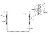
図2は、酸化剤槽51への流路形成部52の設置状態を示す斜視図であり、図3は図2の酸化剤槽51及び流路形成部52の縦断面図である。
FIG. 2 is a perspective view showing an installation state of the flow
図2に示されるように、本実施形態における流路形成部52は、内部に空間が形成された一本の中空部材としてのホース521からなり、このホース521が酸化剤槽51の外壁としての側壁511に巻回されることで、流路が形成されている。そして、熱媒供給路563からの冷媒は、ホース521の一端に位置する導入口524aから導入され、ホース521内部の流路を通って側壁511の周囲を周回した後、ホース521の他端に位置する導出口524bから熱媒還流路565へと導出される。このように、流路形成部52の流路は、導入口524a及び導出口524bを除き略密閉されているため、外気との接触が抑制されている。
As shown in FIG. 2, the flow
ホース521は、ゴム(例えば、エチレンプロピレンゴム)等の柔軟性を有する柔軟素材からなり、側壁511に設けられている。これにより、図3のαに示されるように、ホース521が撓んでいるため、接触部522が広い面積で側壁511と接触する。また、本実施形態の柔軟素材は伸縮性も兼ね備えており、ホース521は側壁511に伸張された状態で設けられている。そして、流路形成部52の流路を流通する冷媒は、かかる接触部522及び側壁511を介して酸化剤515と熱交換を行うことになる。このように、酸化剤槽51は被熱交換槽を構成する。
The
このように酸化剤515と熱交換を行い、温められた冷媒は、熱媒還流路565を介して熱媒供給源56に還流される。その後、冷媒は、熱媒供給源56の図示しない冷却部によって冷却された後、熱媒供給路563を介して再びホース521に導入されることになる。
The refrigerant that has been heated and exchanged with the
以上の流路形成部52及び熱媒供給源56は、熱交換手段を構成する。
The flow
[作用効果]
本実施形態によれば、以下のような作用効果が得られる。
[Function and effect]
According to this embodiment, the following effects can be obtained.
流路を酸化剤槽51の側壁511に熱伝導可能に設けたので、流路を流通する冷媒と、酸化剤槽51に収容された酸化剤との間で熱交換が行われる。
ここで、導入口524a及び導出口524bを除いて流路を略密閉したので、外気中を漂う藻の胞子が冷媒に混入することが抑制され、酸化剤槽51の側壁511に藻が発生するのが抑制される。これにより、冷媒と酸化剤との効率的な熱交換が継続されるので、酸化剤の分解を充分に抑制でき且つ環境負荷を軽減できる。
Since the flow path is provided in the
Here, since the flow path is substantially sealed except for the
ホース521を側壁511に設けることで流路を形成したので、ホース521及び側壁511の密着性が不充分になったとしても、流路から冷媒が漏出する事態は起こりにくい。このため、藻の発生がより確実に抑制されるため、酸化剤の分解をより確実に抑制でき且つ環境負荷をより確実に軽減できる。
Since the flow path is formed by providing the
ホース521を柔軟素材で構成したので、ホース521が撓み、広範囲に亘って側壁511に密着する。これにより、側壁511が外気から断熱されるので、酸化剤の分解効率及び環境負荷の軽減効率を向上できる。
Since the
伸縮素材からなるホース521を伸張された状態で側壁511に設けたので、伸縮素材の収縮力によって、ホース521が側壁511に自然に密着する。また、伸縮素材の収縮に伴ってホース521が撓むため、ホース521の接触部522と側壁511との接触面積が増加し、冷媒と酸化剤との熱交換が促進される。これにより、酸化剤の分解効率及び環境負荷の軽減効率を相乗的に向上できる。
Since the
導出口524bから導出された冷媒が熱媒供給源56に還流され、やがて導入口524aから流路へと導入される。このように、冷媒が再利用されるため、環境負荷をより軽減できる。
The refrigerant led out from the lead-out
酸化剤槽51に酸化剤を収容したので、酸化剤の分解を充分に抑制でき且つ環境負荷を軽減できる。これにより、スライムコントロール剤の使用の度ごとに、酸化剤の残存濃度を測定し、この濃度に応じて酸化剤供給弁513及び窒素供給弁533の開度を調節するといった煩雑な作業が軽減される。よって、水処理効率に優れたスライムコントロール剤を簡便に生成できる。
Since the oxidizing agent is stored in the
<第2実施形態>
図4は、本発明の第2実施形態に係る流路形成部52Aの概略構成図であり、図5は酸化剤槽51への流路形成部52Aの設置状態を示す図である。本実施形態は、流路形成部52Aの構成において、第1実施形態と異なる。
Second Embodiment
FIG. 4 is a schematic configuration diagram of a flow
図4に示されるように、流路形成部52Aは長さが短いホース521Aを複数有し、これらホース521Aが互いに平行に配置されている。これらホース521A群の一端は第1合流部材523aの側部に接続され、他端は第2合流部材523bの側部に接続されている。
As shown in FIG. 4, the flow
第1合流部材523aの反対側部には、リング状の固定部525aが固着され、この固定部525aはリング状の被固定部527bと係合し固定されている。この被固定部527bは、帯状の係合バンド526の一端に固着される一方、この係合バンド526の他端には、先端C字状の係止部527aが固着されている。この係止部527aは、第2合流部材523bの反対側部に固着されたリング状の被係止部525bに係止可能である。なお、係合バンド526は非伸縮素材からなる一方、図示しない長さ調節機構を有しており、この長さ調節機構によって長さが自在に調節可能である。
A ring-shaped
図5に示されるように、ホース521Aは側壁511に巻回され、この状態で係止部527aは被係止部525bに係止されている。そして、長さ調節機構によって係合バンド526の長さが適宜調節され、これによりホース521Aが伸張状態で側壁511に設けられている。
As shown in FIG. 5, the
ところで、第1合流部材523a及び第2合流部材523bの内部には、図示しない合流路がそれぞれ形成されている。この合流路は、第1合流部材523aに設けられた導入口524aA、及び第2合流部材523bに設けられた導出口524bAを、ホース521Aの両端と連通する。このため、導入口524aAから合流路に導入された冷媒は、ホース521Aの各々が形成する流路を流通し、側壁511の外周を略一周した後、再び合流して導出口524bAから導出される。
Incidentally, unshown joining channels are formed in the first joining
なお、本実施形態では、側壁511の外周の一部分にはホース521Aが巻回されていないが、この部分ができる限り狭くなるよう、側壁511の外周を考慮してホース521Aの長さを設定することが好ましい。また、ホース521Aの設置技術は特に限定されず、各部材の構成及び連結構造等も特に限定されるものではない。
In this embodiment, the
[作用効果]
本実施形態によれば、前述した第1実施形態による作用効果に加えて、以下のような作用効果が得られる。
[Function and effect]
According to this embodiment, in addition to the operational effects of the first embodiment described above, the following operational effects are obtained.
521Aを複数設けるとともに、各ホース521Aの長さを短縮したので、導入口524aAから導入された冷媒は、酸化剤515と短時間のみ熱交換し、温められる前に速やかに導出口524bAから導出されて再び冷却される。これにより、高容量の酸化剤515が充分に低温の冷媒と熱交換できるため、酸化剤515の分解をより充分に抑制できる。また、冷媒は還流されて再利用されるため、環境負荷の増大も最低限に抑制できる。
Since the plurality of 521A are provided and the length of each
冷媒が還流する経路全体の長さが短縮されるので、冷媒の流通に必要な圧力が低下する。これにより、圧力損失を低減でき、熱媒供給源56を経済的に稼動できる。
Since the entire length of the path through which the refrigerant circulates is shortened, the pressure required for the circulation of the refrigerant decreases. Thereby, pressure loss can be reduced and the heat
<第3実施形態>
図6は、本発明の第3実施形態に係る反応システム50Bの概略構成図である。本実施形態は、温度差検出部57及び冷媒調整部58を具備する点において、第1実施形態と異なる。
<Third Embodiment>
FIG. 6 is a schematic configuration diagram of a
即ち、反応システム50Bは温度差検出部57を更に備え、この温度差検出部57は熱媒供給路563を流れる冷媒の温度から、熱媒還流路565を流れる冷媒の温度を差し引いた温度差ΔTを検出する。この検出値は、酸化剤槽51内の酸化剤515との熱交換によって冷媒が温められた程度の指標であり、冷媒調整部58に送信される。
That is, the
冷媒調整部58は、受信した検出値に基づいて、熱媒供給源56の冷却部561を制御する。即ち、冷媒調整部58は、検出値の多少に応じて冷却部561の出力を増減し、これにより酸化剤515と熱交換を行う冷媒が所定温度に維持される。
The
なお、本実施形態では、温度差ΔTを、熱媒供給路563を流れる冷媒の温度から、熱媒還流路565を流れる冷媒の温度を差し引いた値としたが、その逆であってもよい。
In the present embodiment, the temperature difference ΔT is a value obtained by subtracting the temperature of the refrigerant flowing through the heat
[作用効果]
本実施形態によれば、前述した第1実施形態による作用効果に加えて、以下のような作用効果が得られる。
[Function and effect]
According to this embodiment, in addition to the operational effects of the first embodiment described above, the following operational effects are obtained.
冷媒調整部58を更に設けたので、酸化剤515と熱交換を行う冷媒が所定温度に維持される。これにより、酸化剤515が所望の温度に常時冷却されるので、酸化剤515の分解をより確実に抑制できる。しかも、冷却部561の出力を必要最低限に制御することで、環境負荷をより軽減できる。
Since the
酸化剤515は腐食性を有するため、酸化剤515の温度を継続的に計測する場合、温度計の消耗が激しく、維持費用が増加する。しかし、本実施形態によれば、温度差検出部57を酸化剤槽51の外部に設け、温度差ΔTに基づいて冷媒調整部58が制御を行う構成を採用したので、維持費用を削減でき且つ冷却部561の制御を継続的に行うことができる。
Since the
<試験例1>
有効塩素濃度13%の次亜塩素酸ナトリウム水溶液を、37℃又は20℃の条件下にそれぞれ静置し、30日経過後に次亜塩素酸ナトリウム濃度を測定した。
<Test Example 1>
A sodium hypochlorite aqueous solution having an effective chlorine concentration of 13% was allowed to stand at 37 ° C. or 20 ° C., and the sodium hypochlorite concentration was measured after 30 days.
その結果、37℃の条件下の濃度低下は約40%である一方、20℃の条件下における濃度低下は10%以下にとどまった。これにより、次亜塩素酸ナトリウム水溶液の液温を低く保つことで、次亜塩素酸ナトリウムの分解を大幅に抑制できることが確認された。 As a result, the concentration decrease under the condition of 37 ° C. was about 40%, while the concentration decrease under the condition of 20 ° C. was only 10% or less. Thereby, it was confirmed that decomposition | disassembly of sodium hypochlorite can be suppressed significantly by keeping the liquid temperature of sodium hypochlorite aqueous solution low.
<実施例>
稼動中のある製紙工場において、実施例を行った。この工場建屋内に設置されていた次亜塩素酸ナトリウム槽は、収容可能量5000Lのポリエチレン製タンクであり、槽の周囲を取り囲む壁部材は設置されておらず、気温変化は屋外の外気温と略等しかった。
<Example>
The example was carried out at a paper mill in operation. The sodium hypochlorite tank installed in this factory building is a polyethylene tank with a capacity of 5000 L, no wall members are installed around the tank, and the temperature change is the outdoor outdoor temperature. It was almost equal.
かかるタンクの外周に、エチレンプロピレンゴム製熱交換器「クーリングロールCRN」(第一工業社製、長さ5470mm×幅900mm、熱交換面積4.8m2)を巻回した。この熱交換器と、冷却能力1kWの小型空冷式チラー「RSK−400F」(オリオン社製)との間で、20℃の冷水を20L/分の流量で循環通水させ、タンク内の次亜塩素酸ナトリウム水溶液を冷却した。 An ethylene propylene rubber heat exchanger “cooling roll CRN” (Daiichi Kogyo Co., Ltd., length 5470 mm × width 900 mm, heat exchange area 4.8 m 2 ) was wound around the outer periphery of the tank. Between this heat exchanger and a small air-cooled chiller “RSK-400F” (manufactured by Orion Co., Ltd.) having a cooling capacity of 1 kW, cold water at 20 ° C. is circulated at a flow rate of 20 L / min. The aqueous sodium chlorate solution was cooled.
[評価1]
この状態を約60日間に亘り維持し、その間、定期的に次亜塩素酸ナトリウム水溶液の温度を測定した。この結果を、外気温の変化とともに図8に示す。
[Evaluation 1]
This state was maintained for about 60 days, during which the temperature of the sodium hypochlorite aqueous solution was measured periodically. This result is shown in FIG. 8 together with changes in the outside air temperature.
図8に示されるように、試験期間中の外気温は、平均値が約30℃であり、最高値が33℃以上に至る高温であった。冷却を開始する前における次亜塩素酸案トリウム水溶液の温度も、外気温と同様に30℃を超えていた。なお、新しい次亜塩素酸案トリウム水溶液を補充すると、極めて短期間に限り液温が低下するが、その後速やかに昇温していた。 As shown in FIG. 8, the outside air temperature during the test period was a high temperature having an average value of about 30 ° C. and a maximum value of 33 ° C. or higher. The temperature of the hypochlorous acid proposed thorium aqueous solution before the start of cooling exceeded 30 ° C., similarly to the outside air temperature. In addition, when a new hypochlorous acid proposed thorium aqueous solution was replenished, the liquid temperature decreased for a very short period of time, but then the temperature was rapidly increased.
これに対して、冷却を開始すると、その直後に液温が急低下し、20℃〜23℃の範囲で安定した。20℃の条件下では少なくとも30日間に亘り次亜塩素酸ナトリウムの分解が大幅に抑制された試験例1の結果を踏まえると、本実施例に係る装置及び方法によって、次亜塩素酸ナトリウムの分解が大幅に抑制されていることが示唆される。 On the other hand, when the cooling was started, the liquid temperature rapidly dropped immediately after that and stabilized in the range of 20 ° C to 23 ° C. Based on the result of Test Example 1 in which the decomposition of sodium hypochlorite was significantly suppressed over 20 days under the condition of 20 ° C., the decomposition of sodium hypochlorite was achieved by the apparatus and method according to this example. Is significantly suppressed.
[評価2]
タンク冷却前及び冷却後において、次亜塩素酸ナトリウム槽から放出した次亜塩素酸ナトリウムを、槽へ補充した溶液の濃度に基づきモル比が1:1となるように臭化アンモニウムを反応した。生成された反応生成物のpHを測定した。
[Evaluation 2]
Before and after cooling the tank, ammonium bromide was reacted with sodium hypochlorite released from the sodium hypochlorite tank so that the molar ratio was 1: 1 based on the concentration of the solution replenished to the tank. The pH of the produced reaction product was measured.
すると、タンク冷却前では、次亜塩素酸ナトリウムの補充直後の反応で得られた反応生成物のpHは9.7であったが、補充48時間後の反応で得られた反応生成物のpHは9.3であった。 Then, before the tank cooling, the pH of the reaction product obtained by the reaction immediately after replenishment of sodium hypochlorite was 9.7, but the pH of the reaction product obtained by the reaction 48 hours after replenishment. Was 9.3.
図8に示されるように、タンク冷却前の補充48時間後の液温は、既に昇温が進行しており、27〜28℃である。この事実を踏まえると、かかるpH低下は、高アルカリ性である次亜塩素酸ナトリウムの濃度低下によるものと推測される。pHが低下すると、ブロマミン化合物が更に不安定化し、分解がより促進されるのみならず、未反応の臭化アンモニウムが増加するため、非効率になる。 As shown in FIG. 8, the temperature of the liquid 48 hours after replenishment before cooling the tank has already been increased, and is 27 to 28 ° C. Based on this fact, it is estimated that this pH decrease is due to a decrease in the concentration of highly alkaline sodium hypochlorite. When the pH is lowered, the bromamine compound is further destabilized and the decomposition is not only promoted, but also the amount of unreacted ammonium bromide increases, resulting in inefficiency.
これに対して、タンク冷却後では、補充7日後の反応で得られた反応生成物のpHは9.7であり、補充直後のpHと有意には変わらなかった。図8に示されるように、タンク冷却後における液温は20℃〜23℃の範囲で安定していた事実を踏まえると、本評価試験における結果は、次亜塩素酸ナトリウムの分解が充分に抑制されていたことによることが強く示唆される。 In contrast, after cooling the tank, the pH of the reaction product obtained by the reaction 7 days after the replenishment was 9.7, which was not significantly different from the pH immediately after the replenishment. As shown in FIG. 8, based on the fact that the liquid temperature after cooling the tank was stable in the range of 20 ° C. to 23 ° C., the results in this evaluation test showed that the decomposition of sodium hypochlorite was sufficiently suppressed. It is strongly suggested that it was due to what was done.
<変形例>
本発明は前記実施形態に限定されるものではなく、本発明の目的を達成できる範囲での変形、改良等は本発明に含まれるものである。
<Modification>
The present invention is not limited to the above-described embodiment, and modifications, improvements, and the like within the scope that can achieve the object of the present invention are included in the present invention.
前記実施形態では、流路を形成するために、中空部材であるホース521を用いたが、これに限られない。例えば、図7に示される52Cは、断面C字状の部分円環管521Cからなり、この部分円環管521Cの切欠部分が側壁511に密着されることで、流路が形成されている。即ち、この態様では、流路を流通する冷媒が、側壁511に直接的に接触することになる。ただし、漏水を抑制するべく、部分円環管521Cは金属等の高硬度部材で構成されることが好ましい。
In the embodiment, the
前記実施形態では、ホース521が側壁511の中腹に巻回されているが、これに限られず、全体に巻回されていてもよい。また、前記実施形態では、一本のホース521が側壁511に巻回されているが、これに限られず、複数本のホースを巻回してもよく、ホースを周方向ではなく酸化剤槽51の軸方向に沿って設けてもよい。ホース521は、側壁511以外の外壁、例えば下壁及び上壁に設けてもよいが、酸化剤515との熱交換効率を向上できる点では、側壁511又は下壁に設けることが好ましい。
In the above-described embodiment, the
前記実施形態では、導出口524bから導出された冷媒は熱媒還流路565を介して熱媒供給源56に還流されるが、これに限られず、冷媒の一部又は全部を廃棄してもよい。
In the above embodiment, the refrigerant led out from the
前記実施形態では、反応システム50を抄紙システム10に設置したが、これに限られず、水処理が必要な水が生成される種々の箇所に使用できる。また、本実施形態では熱媒として冷媒を用いたが、熱交換する対象及び目的に応じて、温媒を用いてもよい。
In the said embodiment, although the
50、50B 反応システム
51 酸化剤槽(前駆体槽、被熱交換槽)
511 側壁(外壁)
513 酸化剤供給弁(反応手段)
515 酸化剤(反応前駆体)
52、52A、52C 流路形成部(熱交換手段)
521、521A ホース(中空部材)
524a、524aA 導入口
524b、524bA 導出口
53 含窒素化合物槽(前駆体槽)
533 窒素供給弁(反応手段)
54 反応槽(反応手段)
56 熱媒供給源(熱交換手段、熱媒供給手段、還流手段)
563 熱媒供給路(熱媒供給手段)
565 熱媒還流路(還流手段)
50,
511 Side wall (outer wall)
513 Oxidant supply valve (reaction means)
515 Oxidizing agent (reaction precursor)
52, 52A, 52C Flow path forming part (heat exchange means)
521, 521A Hose (hollow member)
524a,
533 Nitrogen supply valve (reaction means)
54 Reaction tank (reaction means)
56 Heat medium supply source (heat exchange means, heat medium supply means, reflux means)
563 Heat medium supply path (heat medium supply means)
565 Heat medium reflux path (reflux means)
Claims (6)
反応前駆体の各々を収容する複数の前駆体槽と、
前記前駆体槽の各々からの前駆体同士の反応を行う反応手段と、
前記複数の前駆体槽から選択される一以上の被熱交換槽に収容された反応前駆体と熱交換する熱交換手段と、を備え、
前記熱交換手段は、前記被熱交換槽の外壁に熱伝導可能に設けられ熱媒が流通する流路と、
前記流路に熱媒を供給する熱媒供給手段と、を有し、
前記流路は、前記熱媒供給手段に接続され熱媒が導入される導入口と、熱媒が導出される導出口と、を除いて略密閉され、
前記流路は、前記導入口及び前記導出口を除き略密閉された空間が内部に形成された複数の中空部材が前記外壁に設けられることで形成され、
前記反応前駆体は、酸化剤及び含窒素化合物を含み、少なくとも前記酸化剤は、前記被熱交換槽に収容され、
前記反応手段は、前記酸化剤及び前記含窒素化合物を反応して、スライムコントロール剤を生成し、
前記中空部材は、柔軟性を有する柔軟素材からなる反応システム。 A reaction system for reacting a plurality of reaction precursors,
A plurality of precursor vessels containing each of the reaction precursors;
Reaction means for reacting precursors from each of the precursor tanks;
Heat exchange means for exchanging heat with a reaction precursor housed in one or more heat exchange tanks selected from the plurality of precursor tanks,
The heat exchange means is provided on the outer wall of the heat exchange tank so as to be capable of conducting heat, and a flow path through which a heat medium flows;
A heating medium supply means for supplying a heating medium to the flow path,
The flow path is substantially sealed except for an introduction port connected to the heating medium supply means and introduced with a heating medium, and an outlet port where the heating medium is led out,
The flow path is formed by providing a plurality of hollow members formed in a substantially sealed space inside the outer wall except for the inlet and the outlet.
The reaction precursor includes an oxidizing agent and a nitrogen-containing compound, and at least the oxidizing agent is accommodated in the heat exchange tank,
The reaction means reacts the oxidizing agent and the nitrogen-containing compound to produce a slime control agent ,
The hollow member is a reaction system made of a flexible material having flexibility .
反応前駆体の各々を収容する複数の前駆体槽から選択される一以上の被熱交換槽の外壁に、流路を熱伝導可能に設け、熱媒が導入される導入口及び熱媒が導出される導出口を除いて略密閉し、
前記流路は、前記導入口及び前記導出口を除き略密閉された空間が内部に形成された複数の中空部材が前記外壁に設けられることで形成され、
前記反応前駆体は、酸化剤及び含窒素化合物を含み、
前記方法は、少なくとも前記酸化剤を前記被熱交換槽に収容し、
前記酸化剤及び前記含窒素化合物を反応して、スライムコントロール剤を生成する手順を有し、
前記流路の導入口から熱媒を供給する手順を有し、
前記中空部材は、柔軟性を有する柔軟素材からなり、
前記方法は、前記中空部材を撓んだ状態で前記外壁に設ける方法。 A method of producing a reaction product by reacting a plurality of reaction precursors,
A flow path is provided on the outer wall of one or more heat exchange tanks selected from a plurality of precursor tanks containing each of the reaction precursors so as to conduct heat, and an introduction port and a heat medium are introduced. Almost sealed except for the outlet
The flow path is formed by providing a plurality of hollow members formed in a substantially sealed space inside the outer wall except for the inlet and the outlet.
The reaction precursor includes an oxidizing agent and a nitrogen-containing compound,
In the method, at least the oxidizing agent is accommodated in the heat exchange tank,
Reacting the oxidizing agent and the nitrogen-containing compound to produce a slime control agent;
Have a procedure for supplying the heating medium from the inlet of the channel,
The hollow member is made of a flexible material having flexibility,
The method is a method in which the hollow member is provided on the outer wall in a bent state .
The method according to claim 4 or 5 , further comprising a step of refluxing the heating medium led out from the outlet and reintroducing it from the inlet.
Priority Applications (1)
| Application Number | Priority Date | Filing Date | Title |
|---|---|---|---|
| JP2008022057A JP5433951B2 (en) | 2008-01-31 | 2008-01-31 | Reaction system and method for producing reaction product |
Applications Claiming Priority (1)
| Application Number | Priority Date | Filing Date | Title |
|---|---|---|---|
| JP2008022057A JP5433951B2 (en) | 2008-01-31 | 2008-01-31 | Reaction system and method for producing reaction product |
Publications (2)
| Publication Number | Publication Date |
|---|---|
| JP2009179617A JP2009179617A (en) | 2009-08-13 |
| JP5433951B2 true JP5433951B2 (en) | 2014-03-05 |
Family
ID=41033857
Family Applications (1)
| Application Number | Title | Priority Date | Filing Date |
|---|---|---|---|
| JP2008022057A Active JP5433951B2 (en) | 2008-01-31 | 2008-01-31 | Reaction system and method for producing reaction product |
Country Status (1)
| Country | Link |
|---|---|
| JP (1) | JP5433951B2 (en) |
Family Cites Families (8)
| Publication number | Priority date | Publication date | Assignee | Title |
|---|---|---|---|---|
| JPS6142910Y2 (en) * | 1978-12-26 | 1986-12-05 | ||
| ATE1972T1 (en) * | 1979-09-13 | 1982-12-15 | Ciba-Geigy Ag | PROCESS FOR REMOVAL OF THE HEAT OF REACTION OF EXOTHERMAL CHEMICAL REACTIONS AND DEVICE FOR CARRYING OUT THE PROCESS. |
| JP3036892B2 (en) * | 1991-06-14 | 2000-04-24 | 昭和アルミニウム株式会社 | Heat exchanger |
| JPH061271U (en) * | 1992-06-16 | 1994-01-11 | 日本容器工業株式会社 | Cooling mat for sake tank and sake tank |
| JPH11281291A (en) * | 1998-03-31 | 1999-10-15 | Sharp Corp | Heat exchanger |
| JP2003265485A (en) * | 2002-03-19 | 2003-09-24 | Senko Medical Instr Mfg Co Ltd | Internal organ cooling jacket |
| JP4978002B2 (en) * | 2005-12-07 | 2012-07-18 | Jfeエンジニアリング株式会社 | Ballast water treatment method |
| JP5213299B2 (en) * | 2005-10-11 | 2013-06-19 | ソマール株式会社 | Method and apparatus for adding slime control agent |
-
2008
- 2008-01-31 JP JP2008022057A patent/JP5433951B2/en active Active
Also Published As
| Publication number | Publication date |
|---|---|
| JP2009179617A (en) | 2009-08-13 |
Similar Documents
| Publication | Publication Date | Title |
|---|---|---|
| JP5305230B2 (en) | Monopersulfuric acid production method and monopersulfuric acid continuous production apparatus | |
| JP5308977B2 (en) | Hot water system | |
| JP5433951B2 (en) | Reaction system and method for producing reaction product | |
| JP5045618B2 (en) | Water treatment agent and water treatment method | |
| CN211111050U (en) | Device for continuously preparing sodium hypochlorite | |
| CN106495385A (en) | A kind of supercritical oxidation method for processing waste water | |
| US7517407B2 (en) | Cooling system and method for a paper coating device in a papermaking apparatus | |
| CN116474704A (en) | Energy-saving sodium hypochlorite disinfectant production system and production process | |
| JP4373990B2 (en) | Ozone production equipment | |
| CN207271103U (en) | A kind of liquid caustic soda configured slot | |
| JP2007275817A (en) | Water treatment method | |
| WO2020136997A1 (en) | Operation control method for ice maker | |
| JP2017205773A (en) | Liquid temperature adjustment apparatus | |
| KR102487464B1 (en) | Water disinfection system with cooling device | |
| JP3910842B2 (en) | Double tube heat exchanger | |
| CN114805213A (en) | Clean synthesis method of dibromohydantoin | |
| CN104990336B (en) | High-temperature cooling water system for synthesizing chloroacetic acid | |
| JP7563871B2 (en) | Methane gas generating device and methane gas generating method | |
| CN115448261B (en) | A method for producing sulfuric acid by vacuum concentration of waste sulfuric acid | |
| CN209763265U (en) | Automatic change control heat supply economizer system | |
| CN220366407U (en) | Industrial steam supply and overheating system of nuclear power plant | |
| CN209978432U (en) | Energy supply device for sterilization system and sterilization system | |
| CN218646083U (en) | Heat energy system based on steel slag waste heat | |
| CN211293767U (en) | Temperature control system of coiling wheel | |
| JP7015716B2 (en) | Drug supply device |
Legal Events
| Date | Code | Title | Description |
|---|---|---|---|
| RD02 | Notification of acceptance of power of attorney |
Free format text: JAPANESE INTERMEDIATE CODE: A7422 Effective date: 20090717 |
|
| RD03 | Notification of appointment of power of attorney |
Free format text: JAPANESE INTERMEDIATE CODE: A7423 Effective date: 20090717 |
|
| RD04 | Notification of resignation of power of attorney |
Free format text: JAPANESE INTERMEDIATE CODE: A7424 Effective date: 20090717 |
|
| A621 | Written request for application examination |
Free format text: JAPANESE INTERMEDIATE CODE: A621 Effective date: 20110113 |
|
| A977 | Report on retrieval |
Free format text: JAPANESE INTERMEDIATE CODE: A971007 Effective date: 20130524 |
|
| A131 | Notification of reasons for refusal |
Free format text: JAPANESE INTERMEDIATE CODE: A131 Effective date: 20130604 |
|
| A521 | Request for written amendment filed |
Free format text: JAPANESE INTERMEDIATE CODE: A523 Effective date: 20130729 |
|
| A131 | Notification of reasons for refusal |
Free format text: JAPANESE INTERMEDIATE CODE: A131 Effective date: 20130813 |
|
| A521 | Request for written amendment filed |
Free format text: JAPANESE INTERMEDIATE CODE: A523 Effective date: 20131008 |
|
| TRDD | Decision of grant or rejection written | ||
| A01 | Written decision to grant a patent or to grant a registration (utility model) |
Free format text: JAPANESE INTERMEDIATE CODE: A01 Effective date: 20131112 |
|
| A61 | First payment of annual fees (during grant procedure) |
Free format text: JAPANESE INTERMEDIATE CODE: A61 Effective date: 20131125 |
|
| R150 | Certificate of patent or registration of utility model |
Ref document number: 5433951 Country of ref document: JP Free format text: JAPANESE INTERMEDIATE CODE: R150 Free format text: JAPANESE INTERMEDIATE CODE: R150 |
|
| R250 | Receipt of annual fees |
Free format text: JAPANESE INTERMEDIATE CODE: R250 |