JP5427778B2 - Method and system for dental planning - Google Patents
Method and system for dental planning Download PDFInfo
- Publication number
- JP5427778B2 JP5427778B2 JP2010508735A JP2010508735A JP5427778B2 JP 5427778 B2 JP5427778 B2 JP 5427778B2 JP 2010508735 A JP2010508735 A JP 2010508735A JP 2010508735 A JP2010508735 A JP 2010508735A JP 5427778 B2 JP5427778 B2 JP 5427778B2
- Authority
- JP
- Japan
- Prior art keywords
- dental
- spatial position
- implant
- connection interface
- patient
- Prior art date
- Legal status (The legal status is an assumption and is not a legal conclusion. Google has not performed a legal analysis and makes no representation as to the accuracy of the status listed.)
- Expired - Fee Related
Links
- 238000000034 method Methods 0.000 title claims description 139
- 238000013439 planning Methods 0.000 title claims description 87
- 239000004053 dental implant Substances 0.000 claims description 89
- 238000004519 manufacturing process Methods 0.000 claims description 16
- 230000008439 repair process Effects 0.000 claims description 4
- 238000011282 treatment Methods 0.000 claims description 4
- 210000000515 tooth Anatomy 0.000 description 107
- 239000007943 implant Substances 0.000 description 101
- 230000036346 tooth eruption Effects 0.000 description 56
- 210000004513 dentition Anatomy 0.000 description 49
- 210000002050 maxilla Anatomy 0.000 description 46
- 210000000988 bone and bone Anatomy 0.000 description 34
- 238000010586 diagram Methods 0.000 description 32
- 210000004872 soft tissue Anatomy 0.000 description 28
- 210000001519 tissue Anatomy 0.000 description 23
- 238000004590 computer program Methods 0.000 description 20
- 210000000214 mouth Anatomy 0.000 description 20
- 239000000047 product Substances 0.000 description 19
- 230000010485 coping Effects 0.000 description 14
- 238000002591 computed tomography Methods 0.000 description 13
- 241000282465 Canis Species 0.000 description 12
- 210000004283 incisor Anatomy 0.000 description 12
- 239000003550 marker Substances 0.000 description 12
- 210000002455 dental arch Anatomy 0.000 description 10
- 230000006870 function Effects 0.000 description 10
- 239000000543 intermediate Substances 0.000 description 9
- 238000004364 calculation method Methods 0.000 description 8
- 210000001847 jaw Anatomy 0.000 description 8
- 239000013598 vector Substances 0.000 description 8
- 230000006978 adaptation Effects 0.000 description 7
- 238000012800 visualization Methods 0.000 description 7
- 238000013461 design Methods 0.000 description 6
- 230000006698 induction Effects 0.000 description 6
- 238000012545 processing Methods 0.000 description 6
- 230000008859 change Effects 0.000 description 5
- 238000012937 correction Methods 0.000 description 5
- 230000000694 effects Effects 0.000 description 5
- 238000000605 extraction Methods 0.000 description 5
- 230000005484 gravity Effects 0.000 description 5
- 230000035876 healing Effects 0.000 description 5
- 238000005259 measurement Methods 0.000 description 5
- 230000004048 modification Effects 0.000 description 5
- 238000012986 modification Methods 0.000 description 5
- 210000003484 anatomy Anatomy 0.000 description 4
- 230000005540 biological transmission Effects 0.000 description 4
- 238000004422 calculation algorithm Methods 0.000 description 4
- 210000004195 gingiva Anatomy 0.000 description 4
- 230000002452 interceptive effect Effects 0.000 description 4
- 239000011505 plaster Substances 0.000 description 4
- 230000008569 process Effects 0.000 description 4
- 210000003625 skull Anatomy 0.000 description 4
- 238000001356 surgical procedure Methods 0.000 description 4
- 238000005266 casting Methods 0.000 description 3
- 230000001055 chewing effect Effects 0.000 description 3
- 238000011960 computer-aided design Methods 0.000 description 3
- 238000001514 detection method Methods 0.000 description 3
- 210000004373 mandible Anatomy 0.000 description 3
- 238000002360 preparation method Methods 0.000 description 3
- 230000002829 reductive effect Effects 0.000 description 3
- 239000000523 sample Substances 0.000 description 3
- 238000003860 storage Methods 0.000 description 3
- 238000012876 topography Methods 0.000 description 3
- 230000007704 transition Effects 0.000 description 3
- 206010016717 Fistula Diseases 0.000 description 2
- 210000004763 bicuspid Anatomy 0.000 description 2
- 230000015572 biosynthetic process Effects 0.000 description 2
- 230000037182 bone density Effects 0.000 description 2
- 239000000919 ceramic Substances 0.000 description 2
- 229940023487 dental product Drugs 0.000 description 2
- 230000003890 fistula Effects 0.000 description 2
- 229910052602 gypsum Inorganic materials 0.000 description 2
- 239000010440 gypsum Substances 0.000 description 2
- 238000002513 implantation Methods 0.000 description 2
- 239000000463 material Substances 0.000 description 2
- 230000013011 mating Effects 0.000 description 2
- 210000005036 nerve Anatomy 0.000 description 2
- 231100000241 scar Toxicity 0.000 description 2
- 230000011218 segmentation Effects 0.000 description 2
- 210000003582 temporal bone Anatomy 0.000 description 2
- 208000002354 Edentulous Jaw Diseases 0.000 description 1
- 201000002154 Pterygium Diseases 0.000 description 1
- 241000746998 Tragus Species 0.000 description 1
- 210000001909 alveolar process Anatomy 0.000 description 1
- 238000004458 analytical method Methods 0.000 description 1
- 210000004204 blood vessel Anatomy 0.000 description 1
- 239000002131 composite material Substances 0.000 description 1
- 238000010276 construction Methods 0.000 description 1
- 210000003464 cuspid Anatomy 0.000 description 1
- 230000007812 deficiency Effects 0.000 description 1
- 239000003479 dental cement Substances 0.000 description 1
- 230000001419 dependent effect Effects 0.000 description 1
- 238000003745 diagnosis Methods 0.000 description 1
- 238000002059 diagnostic imaging Methods 0.000 description 1
- 238000005553 drilling Methods 0.000 description 1
- 238000013399 early diagnosis Methods 0.000 description 1
- 230000001815 facial effect Effects 0.000 description 1
- 239000012467 final product Substances 0.000 description 1
- 238000003384 imaging method Methods 0.000 description 1
- 238000009434 installation Methods 0.000 description 1
- 230000003993 interaction Effects 0.000 description 1
- 230000000670 limiting effect Effects 0.000 description 1
- 238000007726 management method Methods 0.000 description 1
- 230000018984 mastication Effects 0.000 description 1
- 238000010077 mastication Methods 0.000 description 1
- 210000002445 nipple Anatomy 0.000 description 1
- 230000003287 optical effect Effects 0.000 description 1
- 229910052573 porcelain Inorganic materials 0.000 description 1
- 239000000843 powder Substances 0.000 description 1
- 230000000717 retained effect Effects 0.000 description 1
- 230000002441 reversible effect Effects 0.000 description 1
- 239000007787 solid Substances 0.000 description 1
- 125000006850 spacer group Chemical group 0.000 description 1
- 230000008719 thickening Effects 0.000 description 1
- 238000012546 transfer Methods 0.000 description 1
- 238000012384 transportation and delivery Methods 0.000 description 1
Images


Classifications
-
- A—HUMAN NECESSITIES
- A61—MEDICAL OR VETERINARY SCIENCE; HYGIENE
- A61C—DENTISTRY; APPARATUS OR METHODS FOR ORAL OR DENTAL HYGIENE
- A61C13/00—Dental prostheses; Making same
- A61C13/0003—Making bridge-work, inlays, implants or the like
- A61C13/0004—Computer-assisted sizing or machining of dental prostheses
-
- A—HUMAN NECESSITIES
- A61—MEDICAL OR VETERINARY SCIENCE; HYGIENE
- A61B—DIAGNOSIS; SURGERY; IDENTIFICATION
- A61B34/00—Computer-aided surgery; Manipulators or robots specially adapted for use in surgery
- A61B34/10—Computer-aided planning, simulation or modelling of surgical operations
-
- A—HUMAN NECESSITIES
- A61—MEDICAL OR VETERINARY SCIENCE; HYGIENE
- A61C—DENTISTRY; APPARATUS OR METHODS FOR ORAL OR DENTAL HYGIENE
- A61C1/00—Dental machines for boring or cutting ; General features of dental machines or apparatus, e.g. hand-piece design
- A61C1/08—Machine parts specially adapted for dentistry
- A61C1/082—Positioning or guiding, e.g. of drills
- A61C1/084—Positioning or guiding, e.g. of drills of implanting tools
-
- A—HUMAN NECESSITIES
- A61—MEDICAL OR VETERINARY SCIENCE; HYGIENE
- A61C—DENTISTRY; APPARATUS OR METHODS FOR ORAL OR DENTAL HYGIENE
- A61C13/00—Dental prostheses; Making same
-
- A—HUMAN NECESSITIES
- A61—MEDICAL OR VETERINARY SCIENCE; HYGIENE
- A61C—DENTISTRY; APPARATUS OR METHODS FOR ORAL OR DENTAL HYGIENE
- A61C5/00—Filling or capping teeth
- A61C5/70—Tooth crowns; Making thereof
-
- G—PHYSICS
- G16—INFORMATION AND COMMUNICATION TECHNOLOGY [ICT] SPECIALLY ADAPTED FOR SPECIFIC APPLICATION FIELDS
- G16H—HEALTHCARE INFORMATICS, i.e. INFORMATION AND COMMUNICATION TECHNOLOGY [ICT] SPECIALLY ADAPTED FOR THE HANDLING OR PROCESSING OF MEDICAL OR HEALTHCARE DATA
- G16H50/00—ICT specially adapted for medical diagnosis, medical simulation or medical data mining; ICT specially adapted for detecting, monitoring or modelling epidemics or pandemics
- G16H50/50—ICT specially adapted for medical diagnosis, medical simulation or medical data mining; ICT specially adapted for detecting, monitoring or modelling epidemics or pandemics for simulation or modelling of medical disorders
-
- A—HUMAN NECESSITIES
- A61—MEDICAL OR VETERINARY SCIENCE; HYGIENE
- A61B—DIAGNOSIS; SURGERY; IDENTIFICATION
- A61B34/00—Computer-aided surgery; Manipulators or robots specially adapted for use in surgery
- A61B34/10—Computer-aided planning, simulation or modelling of surgical operations
- A61B2034/101—Computer-aided simulation of surgical operations
- A61B2034/102—Modelling of surgical devices, implants or prosthesis
-
- A—HUMAN NECESSITIES
- A61—MEDICAL OR VETERINARY SCIENCE; HYGIENE
- A61B—DIAGNOSIS; SURGERY; IDENTIFICATION
- A61B34/00—Computer-aided surgery; Manipulators or robots specially adapted for use in surgery
- A61B34/10—Computer-aided planning, simulation or modelling of surgical operations
- A61B2034/101—Computer-aided simulation of surgical operations
- A61B2034/105—Modelling of the patient, e.g. for ligaments or bones
-
- A—HUMAN NECESSITIES
- A61—MEDICAL OR VETERINARY SCIENCE; HYGIENE
- A61B—DIAGNOSIS; SURGERY; IDENTIFICATION
- A61B34/00—Computer-aided surgery; Manipulators or robots specially adapted for use in surgery
- A61B34/25—User interfaces for surgical systems
-
- A—HUMAN NECESSITIES
- A61—MEDICAL OR VETERINARY SCIENCE; HYGIENE
- A61C—DENTISTRY; APPARATUS OR METHODS FOR ORAL OR DENTAL HYGIENE
- A61C5/00—Filling or capping teeth
- A61C5/20—Repairing attrition damage, e.g. facets
-
- A—HUMAN NECESSITIES
- A61—MEDICAL OR VETERINARY SCIENCE; HYGIENE
- A61C—DENTISTRY; APPARATUS OR METHODS FOR ORAL OR DENTAL HYGIENE
- A61C7/00—Orthodontics, i.e. obtaining or maintaining the desired position of teeth, e.g. by straightening, evening, regulating, separating, or by correcting malocclusions
- A61C7/002—Orthodontic computer assisted systems
-
- B—PERFORMING OPERATIONS; TRANSPORTING
- B33—ADDITIVE MANUFACTURING TECHNOLOGY
- B33Y—ADDITIVE MANUFACTURING, i.e. MANUFACTURING OF THREE-DIMENSIONAL [3-D] OBJECTS BY ADDITIVE DEPOSITION, ADDITIVE AGGLOMERATION OR ADDITIVE LAYERING, e.g. BY 3-D PRINTING, STEREOLITHOGRAPHY OR SELECTIVE LASER SINTERING
- B33Y80/00—Products made by additive manufacturing
Landscapes
- Health & Medical Sciences (AREA)
- Public Health (AREA)
- General Health & Medical Sciences (AREA)
- Epidemiology (AREA)
- Life Sciences & Earth Sciences (AREA)
- Oral & Maxillofacial Surgery (AREA)
- Animal Behavior & Ethology (AREA)
- Veterinary Medicine (AREA)
- Engineering & Computer Science (AREA)
- Dentistry (AREA)
- Medical Informatics (AREA)
- Biomedical Technology (AREA)
- Pathology (AREA)
- Databases & Information Systems (AREA)
- Data Mining & Analysis (AREA)
- Primary Health Care (AREA)
- Surgery (AREA)
- General Engineering & Computer Science (AREA)
- Nuclear Medicine, Radiotherapy & Molecular Imaging (AREA)
- Robotics (AREA)
- Heart & Thoracic Surgery (AREA)
- Molecular Biology (AREA)
- Dental Tools And Instruments Or Auxiliary Dental Instruments (AREA)
Description
本発明は一般的に歯科医術の分野に関する。さらに詳しくは、本発明は、歯科修復処置をプランニングするため、ならびに歯科修復物および/または歯科修復処置関連要素を製造するための方法およびシステムに関する。 The present invention relates generally to the field of dentistry. More particularly, the present invention relates to methods and systems for planning dental restoration procedures and for manufacturing dental restorations and / or dental restoration procedure related elements.
デンタルインプラントおよび歯科修復物に関するプランニングは、熟練した歯科医の専門的知識および経験に基づいて行われており、これまでは手作業であった。ソフトウェアをベースとしたコンピュータ環境下において仮想的な頭蓋模型およびデンタル模型の視覚化のプランニングを実行することは公知であるが、そのプランニングは歯科医によって手作業で行われてきた。この手作業によるプランニングに基づいて、歯科修復物およびそれに関係する製作物、例えばドリルガイドなどが製作されてきた。そのようなシステムは、例えば、本出願と同一の出願人による国際特許出願WO02/053056およびWO2005/055856に開示されている。しかし、これらのシステムはヒューマンファクターに依存しており、不完全なプランニングがソフトウェアベースのプランニングシステムによって検出されない可能性がある。 The planning for dental implants and dental restorations has been based on the expertise and experience of skilled dentists and has been manual. Although it is known to perform virtual skull and dental model visualization planning in a software-based computer environment, the planning has been done manually by dentists. Based on this manual planning, dental restorations and related products such as drill guides have been produced. Such a system is disclosed, for example, in international patent applications WO 02/053056 and WO 2005/055856 by the same applicant as the present application. However, these systems rely on human factors, and imperfect planning may not be detected by software-based planning systems.
それゆえ、ヒューマンファクターの影響を低減することができる、患者の歯科的修復処置をプランニングするための改善されたシステムおよび/または前述の歯科的修復処置のための少なくとも1つの歯科的構成要素をプランニングする改善されたシステムがあれば有利であろう。 Therefore, an improved system for planning a dental restoration procedure for a patient and / or planning at least one dental component for the aforementioned dental restoration procedure, which can reduce the influence of human factors It would be advantageous to have an improved system.
したがって、本発明の実施形態は、上で特定されているような当技術分野における1以上の欠陥、欠点または問題を、患者の歯科的修復処置のプランニングおよび/その歯科的修復処置に関係した少なくとも1つの歯科修復物および/または製作物のプランニングに有用な方法、システム、コンピュータ・プログラム・プロダクト、コンピュータ可読媒体、医療用ワークステーション、およびグラフィカルインターフェースを提供することにより、単独または何らかの組み合わせで軽減し、緩和し、または排除することを目指している。 Accordingly, embodiments of the present invention address one or more deficiencies, shortcomings or problems in the art as specified above, at least related to the planning of a patient's dental restoration procedure and / or its dental restoration procedure. Mitigates alone or in some combination by providing methods, systems, computer program products, computer readable media, medical workstations, and graphical interfaces useful for planning a single dental restoration and / or product Aims to mitigate, or eliminate.
本発明の種々の異なる態様が添付の独立特許クレームに記載されている。 Various different aspects of the invention are set out in the accompanying independent patent claims.
本発明の1つの態様によれば、頭蓋口腔スペースを有する患者の歯科的修復処置のコンピュータベースのプランニングおよび/またはその歯科的修復処置のための少なくとも1つの歯科的構成要素のコンピュータベースのプランニングに有用な方法が提供される。この方法は、歯科修復物の第1デンタルユニットの、前記頭蓋口腔スペース内における、第1境界面の第1空間位置を決定するステップと、前記歯科修復物の第2デンタルユニットの、前記第1境界面から隔たった位置の前記頭蓋口腔スペース内における、第2境界面の第2空間位置を決定するステップと、前記第1空間位置および第2空間位置のうちの少なくとも1つに対して相対的な、前記少なくとも1つの歯科的構成要素のうちの少なくとも一部の、第3空間位置を決定するステップと、を含む。 According to one aspect of the present invention, computer-based planning of a dental restoration procedure for a patient having a cranial oral space and / or computer-based planning of at least one dental component for the dental restoration procedure. A useful method is provided. The method includes determining a first spatial position of a first interface of the first dental unit of a dental restoration in the cranial oral cavity space, and the first dental unit of the second dental unit of the dental restoration. Determining a second spatial position of a second boundary surface within the cranial oral cavity space spaced from the boundary surface, relative to at least one of the first spatial position and the second spatial position Determining a third spatial position of at least a portion of the at least one dental component.
本発明の第2の態様によれば、頭蓋口腔スペースを有する患者の歯科的修復処置のコンピュータベースのプランニングおよび/またはその歯科的修復処置のための少なくとも1つの歯科的構成要素のコンピュータベースのプランニングに有用なシステムが提供される。そのシステムは、歯科修復物の第1デンタルユニットの、前記頭蓋口腔スペース内における、第1境界面の第1空間位置を決定するための第1ユニットと、前記歯科修復物の第2デンタルユニットの、前記第1境界面から隔たった位置の前記頭蓋口腔スペース内における、第2境界面の第2空間位置を決定するための第2ユニットと、前記第1空間位置および第2空間位置のうちの少なくとも1つに対して相対的な、前記歯科的構成要素のうちの少なくとも一部の、第3空間位置を決定するための第3ユニットと、を備える。 According to a second aspect of the invention, a computer-based planning of a dental restoration procedure for a patient having a cranial oral space and / or a computer-based planning of at least one dental component for the dental restoration procedure A useful system is provided. The system includes: a first unit for determining a first spatial position of a first interface of a first dental unit of a dental restoration in the cranial oral cavity space; and a second dental unit of the dental restoration. A second unit for determining a second spatial position of the second boundary surface in the cranial oral cavity space at a position separated from the first boundary surface, and among the first spatial position and the second spatial position A third unit for determining a third spatial position of at least some of the dental components relative to at least one.
本発明の第3の態様によれば、コンピュータによって処理されるコンピュータプログラムが提供される。そのコンピュータプログラムは、頭蓋口腔スペースを有する患者の歯科的修復処置のコンピュータベースのプランニングおよび/またはその歯科的修復処置のための少なくとも1つの歯科的構成要素のコンピュータベースのプランニングに有用である。このコンピュータプログラムは、歯科修復物の第1デンタルユニットの、前記頭蓋口腔スペース内における、第1境界面の第1空間位置を決定するための第1コードセグメントと、前記歯科修復物の第2デンタルユニットの、前記第1境界面から隔たった位置の前記頭蓋口腔スペース内における、第2境界面の第2空間位置を決定するための第2コードセグメントと、前記第1空間位置および第2空間位置のうちの少なくとも1つに対して相対的な、前記歯科的構成要素のうちの少なくとも一部の、第3空間位置を決定するための第3コードセグメントと、を含む。 According to a third aspect of the present invention, a computer program processed by a computer is provided. The computer program is useful for computer-based planning of a dental restoration procedure for a patient having a cranial oral space and / or computer-based planning of at least one dental component for the dental restoration procedure. The computer program includes a first code segment for determining a first spatial position of a first interface in the cranial oral space of a first dental unit of a dental restoration, and a second dental of the dental restoration. A second code segment for determining a second spatial position of the second boundary surface in the cranial oral cavity space at a position spaced from the first boundary surface of the unit; and the first spatial position and the second spatial position A third code segment for determining a third spatial position of at least a portion of the dental component relative to at least one of the first and second dental components.
コンピュータプログラムは、コンピュータ可読媒体で具体化されてよい。 The computer program may be embodied on a computer readable medium.
本発明のさらなる態様によれば、デンタルプランニングのためのグラフィカル・ユーザ・インターフェースが提供される。このグラフィカル・ユーザ・インターフェースは、本発明の上述の第1の態様による方法を視覚化するための構成要素を含む。 According to a further aspect of the invention, a graphical user interface for dental planning is provided. This graphical user interface includes components for visualizing the method according to the first aspect of the invention.
本発明のさらなる態様によれば、本発明の上述のさらなる態様のコンピュータプログラムを実行することにより本発明の上述の態様の方法を実施するための医療用ワークステーションが提供される。この医療用ワークステーションは、本発明の上述のさらなる態様のグラフィカル・ユーザ・インターフェースを実施することができる。 According to a further aspect of the present invention there is provided a medical workstation for performing the method of the above aspect of the invention by executing a computer program of the above aspect of the invention. This medical workstation can implement the graphical user interface of the above-described further aspects of the invention.
本発明のさらなる実施形態が従属クレームで定義されており、そこでは、本発明の第2およびそれ以降の態様に関する特徴は、必要な変更が加えられて、第1の態様に関する特徴と同様である。 Further embodiments of the invention are defined in the dependent claims, wherein the features relating to the second and subsequent aspects of the invention are the same as those relating to the first aspect mutatis mutandis. .
本発明の幾つかの実施形態は、ブリッジフレームワークの形、歯科被止の形、したがってブリッジ構造さえをも自動的に適合化することをもたらし、すなわち、デンタルインプラントの位置だけでなく、被止を伴ったブリッジフレームワークをも自動的に適合化することをもたらす。 Some embodiments of the present invention provide for automatically adapting the shape of the bridge framework, the shape of the dental guard, and thus even the bridge structure, i.e. not only the position of the dental implant but also the guard. It also automatically adapts the bridge framework with
幾つかの実施形態は、患者の口腔の石膏模型を作成することや、または歯科的修復処置をプランニングするための患者データを得るために補綴物をCTスキャニングすることを必要としない、歯科的修復処置ならびに歯科修復物および/または前述の歯科的修復処置に関係した製作物を製作することに関する術前のプランニングを提供する。 Some embodiments provide a dental restoration that does not require creating a plaster model of the patient's oral cavity or CT scanning the prosthesis to obtain patient data for planning a dental restoration procedure. Providing pre-operative planning for the treatment and making of the dental restoration and / or the production related to the aforementioned dental restoration procedure.
本発明の幾つかの実施形態は、どのような種類の物理的患者模型をも必要としない、歯科修復物の仮想的プランニングを提供する。 Some embodiments of the present invention provide for virtual planning of dental restorations that do not require any kind of physical patient model.
本発明の幾つかの実施形態は、手作業によるプランニングおよび製作作業が完全に、またはかなりの程度まで回避されるような、歯科的修復処置およびそのために使用される製作物の一層迅速および/または一層信頼性の高いプランニングを提供する。 Some embodiments of the present invention may allow for faster and / or faster dental restoration procedures and / or products used therefor, such that manual planning and fabrication operations may be avoided completely or to a significant degree. Provide more reliable planning.
本発明の幾つかの実施形態では、完全にコンピュータベースのプランニングが提供されるため、歯科的修復処置およびそのために使用される製作物のプランニング中に誤りが生じる可能性が低減される。 In some embodiments of the present invention, fully computer-based planning is provided, reducing the likelihood of errors during the planning of dental restoration procedures and the products used therefor.
本発明の幾つかの実施形態は、頭蓋口腔スペースを有する患者の歯科的修復処置の完全に仮想的なコンピュータベースの提案、および/または前述の歯科的修復処置のための少なくとも1つの歯科的構成要素の完全に仮想的なコンピュータベースの提案を提供する。 Some embodiments of the present invention provide a completely virtual computer-based proposal for a dental restoration procedure for a patient having a cranial oral space and / or at least one dental configuration for the aforementioned dental restoration procedure Provides a completely virtual computer-based proposal for elements.
本発明の幾つかの実施形態では、頭蓋口腔スペースを有する患者の歯科的修復処置の提案が完全に自動的に提供され、および/または前述の歯科的修復処置のための少なくとも1つの歯科的構成要素の提案が完全に自動的に提供され、前述の提案は前記頭蓋口腔スペースに関する患者データに基づいている。 In some embodiments of the invention, a proposal for a dental restoration procedure for a patient having a cranial oral space is provided fully automatically and / or at least one dental configuration for the aforementioned dental restoration procedure Element proposals are provided fully automatically, which are based on patient data regarding the cranial oral space.
本発明の幾つかの実施形態では、加工されていない患者データを入力するだけでよく、本プランニング方法の残りの部分は完全に仮想的に果たされ得るため、歯科的修復処置のために使用される製作物を製作する間のトランスファーステップの数が低減される。 In some embodiments of the invention, it is only necessary to enter unprocessed patient data, and the rest of the planning method can be performed virtually virtually, so it is used for dental restoration procedures. The number of transfer steps during the production of the produced product is reduced.
本発明の幾つかの実施形態は、最終的な配置に先んじて、仮想的歯科修復物の自動的な配置に対する仮想的マニピュレーションのためのユーザ入力またはその自動的な配置のユーザ容認を与えることができるように、歯科的修復処置およびそのために使用される製作物の柔軟性のあるプランニングを提供する。 Some embodiments of the present invention may provide user input for virtual manipulation or automatic acceptance of the automatic placement prior to final placement for virtual dental restoration automatic placement. It provides a flexible planning of the dental restorative procedure and the products used for it.
本発明の幾つかの実施形態は、歯科的修復処置およびそのために使用される製作物のプランニング中に、患者の歯科的状況についての早期診断を提供する。 Some embodiments of the present invention provide an early diagnosis of a patient's dental situation during the planning of dental restoration procedures and the products used therefor.
本発明の幾つかの実施形態は、最適なはめ合い具合の歯科修復物が提供されるように、患者にとっての不都合性および痛みが低減された誘導歯科外科処置を提供する。例えば、補綴物が使用されている患者を再スキャニングする必要性を伴うことなく、最終的な歯科修復物を仮想的にプランニングすることにより、処置を実施する回数および合計処置時間を低減することができる。その上、最終的な歯科修復物とドリルガイドなどのそれに関係した製作物との両方を、単一の自動化手順における同一の入力データから提供することができる。 Some embodiments of the present invention provide a guided dental surgical procedure with reduced patient inconvenience and pain so that an optimally fit dental restoration is provided. For example, by virtually planning the final dental restoration without the need to rescan the patient where the prosthesis is being used, the number of procedures performed and the total procedure time can be reduced. it can. Moreover, both the final dental restoration and its associated production, such as a drill guide, can be provided from the same input data in a single automated procedure.
本明細書で使用する場合の用語「含む/含んでいる」は、記載した特徴、整数、ステップ、またはコンポーネントの存在を明記するものと解釈されるものであって、1つまたはそれ以上の他の特徴、整数、ステップ、コンポーネント、またはそれらの群の存在または追加を排除するものではないことを強調しておきたい。 As used herein, the term “comprising / including” is to be interpreted as specifying the presence of the described feature, integer, step, or component and includes one or more other It should be emphasized that this does not exclude the presence or addition of features, integers, steps, components, or groups thereof.
本発明の実施形態が可能なこれらのおよび他の態様、特徴、および利点は、添付の図面を参照する本発明の実施形態の以下の説明から明らかになるであろう。
本発明の実施態様は添付の図面を参照しながら説明されるであろう。しかしながら、本発明は、多くの異なる形態で実施されることができ、本明細書中に記載される実施形態に限定されると解釈されるべきではない。むしろ、これらの実施形態は、本開示が充分かつ完全であり、当業者に本発明の範囲を充分に伝達できるように提供される。添付の図面において例示される実施形態の詳細な説明において使用される用語は、本発明を制限することを意図していない。図面において、類似の数字は類似の要素を示す。 Embodiments of the present invention will be described with reference to the accompanying drawings. However, the invention can be implemented in many different forms and should not be construed as limited to the embodiments set forth herein. Rather, these embodiments are provided so that this disclosure will be thorough and complete, and will fully convey the scope of the invention to those skilled in the art. The terms used in the detailed description of the embodiments illustrated in the accompanying drawings are not intended to limit the present invention. In the drawings, like numerals indicate like elements.
以下の説明は、上顎(上顎骨)においてプランニングされる、ブリッジフレームワークを含む歯科修復物、特に、デンタルインプラント、ならびにブリッジフレームワークおよび歯科被止構築物を含むブリッジ構造に適用可能な本発明の一実施形態に焦点を合わせている。しかし、本発明はこの適用形態に限定されるものではなく、例えば、スペーサーおよび取り付けられた歯冠を伴っているか否かにかかわらず、単独のインプラントを含め、多くの他の歯科修復物に適用することができ、また、他のインプラント位置との関係において使用されてよく、例えば下顎(下顎骨)においても使用できることが認識されよう。 The following description describes one aspect of the present invention applicable to dental restorations including bridge frameworks, in particular dental implants, and bridge structures including bridge frameworks and dental guard structures, planned in the maxilla (maxilla). Focus on the embodiment. However, the present invention is not limited to this form of application and is applicable to many other dental restorations, including, for example, a single implant, with or without a spacer and attached crown. It will be appreciated that it can also be used in relation to other implant positions, for example in the mandible (mandible).
「歯科修復物」は、デンタルユニット、例えばデンタルインプラント、ブリッジフレームワーク、ブリッジ構造、コーピング、アバットメント、歯冠、被止、およびコーピング等を受け入れることができるように作成された現存する歯などを含む。 “Dental Restoration” refers to dental units such as existing teeth created to accept dental implants, bridge frameworks, bridge structures, copings, abutments, crowns, guards, copings, etc. Including.
「歯科的構成要素」は、歯科修復物の1つまたは幾つかのユニット、さらには、外科用テンプレートなどの歯科修復物の少なくとも一部を設置する際に使用される構成要素を含む。 “Dental components” include components used in installing one or several units of a dental restoration, as well as at least a portion of a dental restoration, such as a surgical template.
「頭蓋口腔スペース」は、そこに歯科修復物が設置されることとなる口腔ならびに周囲の軟組織および骨組織を含む。 The “cranial oral space” includes the oral cavity where the dental restoration will be placed and the surrounding soft and bone tissue.
図1には、歯科的修復処置ならびに歯科修復物および/または前述の歯科的修復処置に関係した製作物をプランニングし、さらには、そのためのデータを自動的もしくは半自動的に作成する改善された方法の一実施形態を例証することを目的としてフローチャートが与えられている。その方法1は以下のステップを含んでいてよい。
100 患者データを取得する、
110 取得された患者データから解剖学的に固定された基準点を決定する、
120 決定済みの解剖学的に固定された基準点に基づいて、デンタルプランニングを実行する、
130 1つまたは複数のインプラントの位置および配向を算出する、
140 インプラント・ブリッジ・フレームワークの自動的適合化、
150 最終的修復物の概算、
160 外科用テンプレートの製作、および
170 歯科修復物の製作。
FIG. 1 shows an improved method for planning a dental restoration procedure and a dental restoration and / or a product related to the aforementioned dental restoration procedure, and further automatically or semi-automatically generating data therefor. A flowchart is provided for purposes of illustrating one embodiment. The method 1 may include the following steps.
100 Get patient data,
110 determining an anatomically fixed reference point from the acquired patient data;
120 Perform dental planning based on the determined anatomically fixed reference points;
130 calculating the position and orientation of one or more implants;
140 Automatic adaptation of the implant bridge framework,
150 Approximate final restoration,
160 Making surgical templates and 170 Making dental restorations.
この後、インプラントおよび歯科修復物は、歯科医により、それ自体は公知の方法で患者に設置することができる。 After this, the implant and the dental restoration can be placed on the patient in a manner known per se by the dentist.
次に、上で概要が説明されている方法の数多くの実施形態を、図2から図30を参照しながらより詳細に説明する。 A number of embodiments of the method outlined above will now be described in more detail with reference to FIGS.
一実施形態においては、無歯顎患者用の歯科修復物および歯科的修復処置、さらにはそれに対応する製作物が仮想的にプランニングされ、以下で、それらについて詳細に説明する。 In one embodiment, dental restorations and dental restoration procedures for edentulous patients, as well as the corresponding artifacts, are virtually planned and will be described in detail below.
100 患者データを取得する
以降の仮想的なデンタルプランニング法で使用されることとなる患者データは様々な方法で取得されてよい。
100 Obtaining Patient Data Patient data to be used in subsequent virtual dental planning methods may be obtained in various ways.
患者の頭蓋口腔スペースが、データを発生させる様々な様式または装置によりスキャニングされてよい。例えば、患者の口腔またはその一部の歯科印象が製作されてよい。CTおよびMRまたはX線などのイメージング法を用いて、表面ベースのデータ取得技術では得ることができない患者のより深部の解剖学的領域についてのデータを得ることができる。患者の口腔内の軟組織をマッピングするためにプローブが用いられてよい。さらに、以降のデンタルプランニング法に対する入力データとして機能する患者データを提供するために、幾つかの入力ソースからのデータが組み合わされてよく、または融合されてよい。 The patient's cranial oral space may be scanned by various manners or devices that generate data. For example, a dental impression of the patient's mouth or part thereof may be created. Imaging methods such as CT and MR or X-rays can be used to obtain data about deeper anatomical regions of the patient that cannot be obtained with surface-based data acquisition techniques. A probe may be used to map soft tissue in the patient's mouth. Further, data from several input sources may be combined or merged to provide patient data that serves as input data for subsequent dental planning methods.
歯科印象は、しばしば、例えば歯の形成や歯肉の輪郭などの、歯および顎のその周囲の部分のインプリントまたは陰性類似を創出するために使用される。また、無歯顎患者の場合には、歯肉のみの印象を取得することもあり得る。その印象は、欠けている歯系組織の歯科的修繕または修復の準備として作られる。歯科印象は、患者の口腔のトポグラフィに関するデータを提供する。 Dental impressions are often used to create imprints or negative resemblances of teeth and their surrounding parts, such as tooth formation and gingival contours. In the case of an edentulous patient, an impression of only gingiva may be acquired. The impression is made as a dental repair or restoration preparation of the missing dental system. The dental impression provides data regarding the topography of the patient's oral cavity.
歯科印象は3次元(3D)スキャナシステムにより直接的にスキャニングされてよい。患者データは、そのような歯科印象から製作された石膏模型を3Dスキャニングすることから取得することもできる。患者データを取得する他の方法は、患者の頭蓋口腔スペースをMRスキャニングする方法、口腔内で3D表面スキャニングする方法、表面プローブを用いて口腔内の軟組織の厚みを決定する方法などを含む。 Dental impressions may be scanned directly by a three-dimensional (3D) scanner system. Patient data can also be obtained from 3D scanning a plaster model made from such a dental impression. Other methods of acquiring patient data include methods of MR scanning the patient's cranial oral space, methods of 3D surface scanning in the oral cavity, methods of determining the thickness of soft tissue in the oral cavity using surface probes, and the like.
上で述べられているように、幾つかの異なる入力ソースから取得された患者データをマッチングさせて、複合患者データを提供することもできる。歯科修復物のプランニングならびにこれらの製作物および関連する製作物の製作をプランニングするためのデータ取得およびマッチングの方法およびシステムは、2007年1月17日に出願された、本出願と同一出願人による同時係属特許出願PCT/EP2007/050426に詳しく記載されており、これをもって、その同時係属特許出願は、参照により、その内容全体が本明細書に組み入れられる。 As mentioned above, patient data obtained from several different input sources can be matched to provide composite patient data. A data acquisition and matching method and system for planning dental restorations and planning for the production of these and related products was filed on Jan. 17, 2007 by the same applicant as the present application. The co-pending patent application is described in detail in PCT / EP2007 / 050426, which is hereby incorporated by reference in its entirety.
患者の咬合線を直接的に取得できないこともあり、例えば、無歯顎患者の場合には、咬合線を取得するための咬合指数を得ることができない。しかし、本発明の方法およびシステムの実施形態では、これは必須ではない。咬合線は、取得された患者データで特定される、解剖学的に固定された基準点から再構成することができる。 The patient's occlusal line may not be obtained directly. For example, in the case of an edentulous patient, the occlusion index for obtaining the occlusal line cannot be obtained. However, this is not essential in the method and system embodiments of the present invention. The occlusal line can be reconstructed from anatomically fixed reference points identified in the acquired patient data.
図2、3および4は、それぞれ、正面図、側面図、および下面図における、CTスキャニングによって取得された患者データに基づく無歯顎上顎骨200の視覚化の例の概略図である。一実施形態においては、上顎骨のCTスキャンデータが、Procera(登録商標)ソフトウェアなどのコンピュータベースのソフトウェアにインポートされる。
2, 3 and 4 are schematic diagrams of examples of visualization of the
110 取得されたデータから、解剖学的に固定された基準点を決定する
本方法のステップ110では、一実施形態におけるデンタルプランニングが、解剖学的に固定された基準点の決定から始まる。解剖学的に固定されたこれらの基準点から開始することにより、歯列弓に沿った1以上の歯の有利な位置が、解剖学的に固定された基準点との関係において定められたこれらの歯の数学的関係に基づいて決定される。例えば、犬歯(前面隅の歯)の自然な位置が顎の歯列弓に沿って決定される。各犬歯は、それぞれ、口腔内における咬合線に沿った咀嚼(チューイング)面によって境界が定められる。それは、特定の歯の実際の位置、ここでは犬歯の実際の位置が、その口腔のデンタルスペース内において仮想的に決定されることを意味している。このようにして、それぞれの歯の第1境界面が決定され、すなわち、咬合線に沿って定められた空間位置における歯の境界面が決定される。定められた空間位置を有する表面は、空間における定められた位置を有している。空間位置を有しているこの第1境界面から、この歯の歯科修復物の残りの構成要素の境界面の空間位置を仮想的に決定することができる。これらの犬歯間のデンタルスペースは、歯列ライブラリーからのテンプレート前歯部で自動的に満たされてよい。この歯列ライブラリーは、例えば、上顎および下顎のそれぞれの歯に対して少なくとも1つの3次元の仮想的テンプレート歯物体を含んでいるデータベースにおいてデジタル形式で提供される。
110 Determine Anatomically Fixed Reference Point from Acquired Data In
同様の方法で、特定の臼歯(大臼歯および小臼歯)の位置を決定することができる。決定された位置における歯と歯の間のすき間は、さらなる歯列、例えば歯列ライブラリーからのテンプレート歯列などで自動的に満たされる。これに関しては、本方法のステップ120から140を参照しながら以下でさらに説明される。 In a similar manner, the position of specific molars (molars and premolars) can be determined. The gap between teeth at the determined position is automatically filled with further dentitions, such as template dentitions from the dentition library. This is further described below with reference to steps 120-140 of the method.
最も近い以下の部分で、取得データから解剖学的に固定された基準点を決定する方法が説明される。図5は、切歯管を示す、無歯顎上顎骨200の下面図における概略図である。上顎骨200の仮想模型は、例えば、取得されたCTデータに基づいている。図6は、第1マーカー600でマーキングされた切歯管500を示す、無歯顎上顎骨200の下面図における概略図である。この第1マーカー600は、解剖学的に固定された第1基準点を定めるのに有用であり、適切な検出アルゴリズムにより、例えば幾何学的な形状検出や表面同定に基づく検出アルゴリズムなどにより、自動的に検出することができる。あるいは、これらの解剖学的に固定された基準点が、それらと同様にして、手作業で同定およびマーキングされてもよい。
In the closest part below, a method for determining anatomically fixed reference points from acquired data is described. FIG. 5 is a schematic diagram in a bottom view of the
解剖学的に固定された第1基準点をマーキングした後、解剖学的に固定されたさらなる基準点がマーキングされる。この様子が図7および8に描かれている。 After marking the first anatomically fixed reference point, further anatomically fixed reference points are marked. This is illustrated in FIGS.
図7は、CTスキャンから取得された場合のような、左右の翼状部700を示す、無歯顎上顎骨200の下面図における概略図である。図8は、それぞれ第2マーカー800および第3マーカー810でマーキングされた翼状部700を示す、図7の無歯顎上顎骨200の下面図における概略図である。これらの第1マーカー600、第2マーカー800および第3マーカー810は、その位置の領域に事前に存在していた解剖学的に自然な歯の位置に関する情報を有する必要性を伴うことなく、少なくとも1本の歯の位置を定めるのに有用である。
FIG. 7 is a schematic diagram in a bottom view of the
解剖学的に固定されたさらなる基準点が、同様な方法で、自動的に検出されてよく、または手作業でマーキングされてよい。しかし、3つの点があれば、空間内における平面を定めるのに十分であり、その平面との関係において少なくとも1本の歯の位置および方向を十分に自動的にプランニングすることができる。 Additional reference points that are anatomically fixed may be detected automatically in a similar manner or may be manually marked. However, having three points is sufficient to define a plane in space, and the position and direction of at least one tooth in relation to that plane can be planned sufficiently automatically.
第1、第2および第3のマーカーによってマーキングされた3つの解剖学的に固定された位置から、図9に示されているような咬合線900が数学的な計算により決定される。さらに、この歯列弓に沿った仮想的な歯の空間位置がこれらの解剖学的に固定された位置から決定される。歯の位置および/または咬合線の空間位置から、少なくとも1つのデンタルインプラントの位置が決定される。咀嚼(チューイング)面、すなわち、咬合線における歯の位置、およびインプラントの空間位置を知ることにより、間置される構造物を決定することができる。このようにして、例えば、それぞれインプラントおよび被止物の空間位置を有する境界面と境界面との間の接続界面にぴったりと適合するブリッジフレームワークが決定される。
From three anatomically fixed positions marked by the first, second and third markers, an
歯の自然な位置を突き止める1つの方法は、例えばKarl Heinz StaubのWO98/20807に開示されている方法などが知られており、この特許文献は、参照により、その内容全体が本明細書に組み入れられる。その方法は、「Das StaubTM−Cranial−System−Reliabilitaet der Messpunkte zur Rekonstruktion der Zahnstellung im zahnlosen Kiefer」(Panagiotis Lampropoulos,Freiburg,2003)でより詳細に説明されており、この文献は、その内容全体が本明細書に組み入れられる。口腔軟組織内の点が解剖学的に固定された基準点として使用される。これらの解剖学的に固定された基準点を使用することにより、上顎および/または下顎における単一の歯または複数の歯の位置を数学的な計算により決定することができる。しかし、Staub法は、歯科印象、石膏鋳造、およびその石膏鋳造での手作業による測定に基づいている。その上、上述の手作業による測定は、軟組織内の点、より正確には、歯科印象をベースとしたその石膏キャストにおける対応する点に基づいている。そして、手作業による測定は、患者が歯を失う前の自然な位置に非常に似通った歯科修復物での歯の位置を算出するソフトウェアに移行されてよい。これにより、これらの測定および数学的な計算に従って製作された歯科修復物により、良好な咬合が達成される。このようにして、高度に正確で予測可能な歯科修復物を提供することができる。上述の解剖学的に固定された基準点は、解剖学的に安定しており、あらゆる患者に存在する。 One method for locating the natural position of a tooth is known, for example, the method disclosed in WO 98/20807 of Karl Heinz Staub, which is hereby incorporated by reference in its entirety. It is done. The method "Das Staub TM -Cranial-System-Reliabilitaet der Messpunkte zur Rekonstruktion der Zahnstellung im zahnlosen Kiefer " (Panagiotis Lampropoulos, Freiburg, 2003) are described in more detail, this document, the entire contents of Incorporated into the specification. A point in the oral soft tissue is used as an anatomically fixed reference point. By using these anatomically fixed reference points, the position of a single tooth or multiple teeth in the upper and / or lower jaw can be determined by mathematical calculations. However, the Staub method is based on dental impressions, gypsum casting and manual measurements in the gypsum casting. Moreover, the manual measurements described above are based on points in the soft tissue, more precisely on the corresponding points in the plaster cast based on dental impressions. The manual measurement may then be transferred to software that calculates the position of the tooth in a dental restoration very similar to the natural position before the patient loses the tooth. A good occlusion is thereby achieved with a dental restoration made according to these measurements and mathematical calculations. In this way, highly accurate and predictable dental restorations can be provided. The anatomically fixed reference points described above are anatomically stable and are present in every patient.
以下では、上顎骨の解剖学的に固定された基準点を決定する1つの例が、図4A〜4Gを参照しながら与えられる。下顎骨の概略的な例が、歯の位置の計算に適用可能な、解剖学的に固定された基準点およびそれらの幾何学的な関係とともに図4Hに示されている。 In the following, one example of determining the anatomically fixed reference point of the maxilla is given with reference to FIGS. A schematic example of the mandible is shown in FIG. 4H with anatomically fixed reference points and their geometric relationships applicable to tooth position calculations.
Staub法による解剖学的に固定された基準点は、相互の関係において対称的に配列される。特定の点を、方向点、誘導点、および結末線と呼ぶ。 The anatomically fixed reference points according to the Staub method are arranged symmetrically with respect to each other. Specific points are called direction points, induction points, and ending lines.
方向点は、翼突鉤の湾曲の方向の変化を正しく決定づける隆起部接続線上の点にある。方向点は、安定したトポグラフィを有しており、上顎骨の両側に存在する。 The direction point is at the point on the ridge connection line that correctly determines the change in the direction of curvature of the blade tip. The direction points have a stable topography and are present on both sides of the maxilla.
誘導点は、後方誘導点をもたらす、乳頭突起の後ろ側の輪郭と上顎の正中軸とが交差する点にある。前方誘導点は、乳頭突起の前方輪郭と上顎の正中軸が交差する点として定められる。それは、解剖学的に安定していない唯一の頭蓋点である。 The induction point is at the point where the contour on the back side of the papillary process and the median axis of the maxilla cross the posterior induction point. The front guidance point is defined as the point where the front contour of the papillary process intersects the median axis of the maxilla. It is the only skull point that is not anatomically stable.
方向点と同様に、結末線は両側に存在し、解剖学的に安定している。結末線は、可動の歯肉と不動の歯肉との間の境界を形成しており、歯肉唇褶の湾曲の位置の変化を決定する。この結末線は、その歯肉唇褶の凹面型から凸面型への移行部にある。 Similar to the direction point, the ending line exists on both sides and is anatomically stable. The ending line forms a boundary between the movable gingiva and the stationary gingiva, and determines the change in the position of the curvature of the gingival lip. This ending line is at the transition from the concave type to the convex type of the gingival lip.
2つの方向点AおよびB、ならびに2つの誘導点CおよびC1の間を線で結ぶことにより、それぞれの斜辺として上述の2つの方向点を伴う2つの二等辺三角形がもたらされる。これらのパラメータは、正常頭蓋咬合平面のベースとして定められるペンタエリアを算出するために使用される。そのペンタエリアは、上顎の切歯点との関係において歯を位置決めするために使用される。 Connecting the two direction points A and B and the two induction points C and C1 with a line results in two isosceles triangles with the two direction points described above as their hypotenuses. These parameters are used to calculate the penta area defined as the base of the normal cranial occlusal plane. The penta area is used to position the tooth in relation to the maxillary incisor point.
上述の上顎切歯点の位置は、ヒトの歯の状態を再構成するときに非常に重要である。その位置は、音声学および美学にとって極めて重要である。下顎の切歯点の正確な位置とともに、上顎切歯点の位置は、咬合の垂直方向の寸法がその正確な位置にまで再構成されることを可能にする。 The position of the maxillary incisal point mentioned above is very important when reconstructing the human tooth condition. Its position is crucial for phonetics and aesthetics. Along with the exact position of the lower incisal point, the position of the upper incisal point allows the vertical dimension of the occlusion to be reconstructed to that exact position.
上述の2つの二等辺三角形A−B−CおよびA−B−C1は、上で説明されているようにして決定される。右側の犬歯の頂点から左側の犬歯の頂点までの距離が決定される。歯槽隆線および口蓋褶などのどのような解剖学的状態もこの位置には影響を及ぼさない。その計算に必要なパラメータはトポグラフィ的に安定しており、患者固有および顎固有の犬歯の位置付けを可能にしている。 The two isosceles triangles A-B-C and A-B-C1 described above are determined as described above. The distance from the apex of the right canine to the apex of the left canine is determined. Any anatomical condition such as alveolar ridge and palatal fistula does not affect this position. The parameters required for the calculation are topographically stable and allow patient-specific and jaw-specific canine positioning.
図4Bには、以下の点が示されている:A=右側方向点、B=左側方向点、C1=後側誘導点、C=前側誘導点、I=切歯点、F=右側犬歯点、G=左側犬歯点、D=右側臼歯点、E=左側臼歯点、FG=犬歯間の距離、DF=臼歯の右側伸展、EG=臼歯の左側伸展、DE=臼歯伸展の横断限界線。 In FIG. 4B, the following points are shown: A = right direction point, B = left direction point, C1 = rear guidance point, C = front guidance point, I = incisor point, F = right canine point. G = left canine point, D = right molar point, E = left molar point, FG = distance between canines, DF = right extension of molar, EG = left extension of molar, DE = transverse limit line of molar extension.
以下の点および距離は、図4Bの点DFIGEによって境界を定められるペンタエリアを決めるために決定される:切歯点I、犬歯の間隔FG、臼歯の間隔DE。 The following points and distances are determined to determine the penta area bounded by point DFIGE in FIG. 4B: incisor point I, canine spacing FG, molar spacing DE.
無歯顎に自然な歯の位置の再構成を提供するため、切歯点Iの2次元的な位置が決定される。この目的で、距離BCが90度旋回されて上顎の正中軸に位置付けされ、これにより、距離NIが得られる。距離NIの開始点は、上述の正中軸と距離ABとが交差する点に相当する(図4D参照)。結果として、式NI=BCがもたらされる。 In order to provide a natural tooth position reconstruction for the edentulous jaw, the two-dimensional position of the incisor point I is determined. For this purpose, the distance BC is turned 90 degrees and positioned on the median axis of the upper jaw, thereby obtaining the distance NI. The starting point of the distance NI corresponds to the point where the above-described median axis and the distance AB intersect (see FIG. 4D). The result is the formula NI = BC.
犬歯間の距離FGは以下のようにして算出される(図4E参照):FG=2BC/3。 The distance FG between the canines is calculated as follows (see FIG. 4E): FG = 2BC / 3.
これは、FGがABに平行であり、かつ、FG<ABと仮定している。距離FGは、切歯乳頭の中心を通る伸展を有している。 This assumes that FG is parallel to AB and FG <AB. The distance FG has an extension through the center of the incisor papilla.
次に、臼歯の伸展が算出される。点DおよびEは、それぞれ、距離FDおよびGEの後ろ側の点である。これらの距離は、上述のペンタエリア内における臼歯伸展に沿った歯科修復物の頬側咬合点の位置を提供する(図4B参照)。距離DEは、点Xにおいて、正中軸を通って垂直に伸びている(図4F参照)。距離PXの計算では、以下の式が適用される:PX=BC×0.55。臼歯伸展の横断限界線DEは、距離XDおよびXEの合計からもたらされ、ここでは、これらの距離の長さは同一である(図4G参照)。 Next, the extension of the molar is calculated. Points D and E are points behind distances FD and GE, respectively. These distances provide the position of the buccal occlusion point of the dental restoration along the molar extension in the penta area described above (see FIG. 4B). The distance DE extends vertically through the median axis at point X (see FIG. 4F). In calculating the distance PX, the following formula is applied: PX = BC × 0.55. The molar extension crossing line DE is derived from the sum of the distances XD and XE, where the lengths of these distances are the same (see FIG. 4G).
[XD=((BC/2)+2mm)]およびDE=2XDであるため、結果として、DE=2×(BC/2)+2mm、すなわち、DE=BC+4mmとなる。式中の2mmという定数は経験的に決定される。 Since [XD = ((BC / 2) +2 mm)] and DE = 2XD, the result is DE = 2 × (BC / 2) +2 mm, that is, DE = BC + 4 mm. The constant of 2 mm in the formula is determined empirically.
点D、F、I、G、Eの3次元的な関係が上述のペンタエリアの位置をもたらす。 The three-dimensional relationship between the points D, F, I, G, and E provides the above-described penta area position.
数学的な一定値が、それぞれ、上顎および下顎のペンタエリアに割り当てられる。この一定値は、3次元空間における切歯点を決定する。その定数は、結末線からの距離として定められ、上顎の場合には19mmになり、下顎の場合には17mmになる。これらの値はまたしても経験的に決定される。上顎における19mmという定数は、点NおよびZと相関関係にあり、数学的に決定されたペンタエリアと組み合わせて、空間内における切歯点を定めている(図4C参照)。距離NY=5mmは、上顎における左側または右側の方向点から、それぞれ、対向する下顎までの距離に相当する。下顎の17mmという定数は、下顎の結末線の中心からその切歯点までの距離として定められる。 Mathematical constant values are assigned to the maxillary and mandibular penta areas, respectively. This constant value determines the incisor point in the three-dimensional space. The constant is determined as the distance from the ending line and is 19 mm for the upper jaw and 17 mm for the lower jaw. These values are again determined empirically. A constant of 19 mm in the upper jaw correlates with points N and Z, and in combination with a mathematically determined penta area, defines the incisor point in space (see FIG. 4C). The distance NY = 5 mm corresponds to the distance from the left or right direction point on the upper jaw to the opposite lower jaw, respectively. The constant of 17 mm of the lower jaw is defined as the distance from the center of the ending line of the lower jaw to its incisor point.
上で述べられているように、Staubは、方向点、誘導点および結末線を決定する。方向点AおよびBは、図8における第2マーカー800および第3マーカー810に相当する。誘導点C1は、後方誘導点をもたらす、乳頭の後ろ側の輪郭と上顎の正中軸とが交差する点にあり、図6における第1マーカー600の下方境界に相当する。2つの方向点AおよびB、ならびに誘導点C1の間を線で結ぶことにより、その斜辺として上述の2つの方向点を伴った二等辺三角形がもたらされる。これらのパラメータは、歯科修復物の歯の位置を仮想的に算出するために使用される。
As stated above, Staub determines direction points, induction points and ending lines. Direction points A and B correspond to the
図9は、第1、第2および第3のマーカー、さらには算出された咬合線900を示す、無歯顎上顎骨200の下面図における概略図である。
FIG. 9 is a schematic diagram in a bottom view of the
下顎における歯の位置決めも同様な原理によって自動的に行うことができる。図4Hには、解剖学的に固定された基準点A’、B’およびC’が描かれている。これらの基準点から、下顎用のペンタエリアが算出され、それに従って歯が位置決めされる。 The positioning of teeth in the lower jaw can be automatically performed according to the same principle. In FIG. 4H anatomically fixed reference points A ', B' and C 'are depicted. From these reference points, the lower jaw penta area is calculated and the teeth are positioned accordingly.
そのような自動的な方法でプランニングされた歯の位置が正しいかどうかをチェックするため、それらの歯が仮想的咬合器に位置付けされてよい。もし、その仮想的咬合器内においてそれらの歯の配列のズレが検出されたときには、該当する歯の位置および方向が自動的に調節されてよい。 In order to check whether the positions of the teeth planned in such an automatic way are correct, they may be positioned in a virtual articulator. If a deviation of the tooth arrangement is detected in the virtual articulator, the position and direction of the corresponding tooth may be automatically adjusted.
例えば、単一の歯修復物をプランニングする場合には、上述の原理によって位置決めされた歯の正しい咬合が、それ以外の歯との関係においてチェックされてよい。残りの歯に関するデータが、例えばCTスキャン、歯科印象、または幾つかのデータソースの組み合わせから得られた取得患者データに提供される。 For example, when planning a single tooth restoration, the correct occlusion of a tooth positioned according to the principles described above may be checked in relation to other teeth. Data about the remaining teeth is provided in acquired patient data obtained, for example, from a CT scan, dental impression, or a combination of several data sources.
Staubによる方法は、解剖学的に固定された基準点である口腔軟組織における同定可能な解剖学的な点をベースとしている。本発明の幾つかの実施形態は、解剖学的に固定された基準点である骨組織における同定可能な解剖学的な点をベースとしている。これらの骨組織ベースの解剖学的に固定された基準点を使用するときに、種々の実施形態において、Staubによる方法が尚も適用可能である。例えば、骨組織を被覆する軟組織の厚みによるオフセットは、上で説明されているような計算で考慮に入れることができる。そのオフセットは、軟組織の厚みの実際の測定に基づくものであってもよいし、または骨組織における解剖学的に固定された基準点の場所におけるオフセットであってもよい。あるいは、例えば経験的な患者データに基づく固定のオフセットを使用することもできる。 The Staub method is based on identifiable anatomical points in oral soft tissue, which are anatomically fixed reference points. Some embodiments of the invention are based on identifiable anatomical points in bone tissue that are anatomically fixed reference points. When using these bone tissue-based anatomically fixed reference points, the Staub method is still applicable in various embodiments. For example, the offset due to the thickness of the soft tissue covering the bone tissue can be taken into account in calculations as described above. The offset may be based on an actual measurement of soft tissue thickness or may be an offset at the location of an anatomically fixed reference point in bone tissue. Alternatively, a fixed offset may be used, for example based on empirical patient data.
歯の位置を再構成するためのStaubによる方法は、本発明の種々の実施形態の範囲内において適用できる多くの可能な方法のうちの1つにすぎない。例えば、上で引用されているPanagiotis Lampropoulosの文献の第5.2章(「Rekonstruktion von Zahnpositionen」)(具体的には、参照により本明細書に組み入れられる)は様々な文献をリストアップしており、それらの文献に従って、咬合線の位置の計算することができ、また、歯科補綴物の歯の位置を解剖学的に固定された点から再構成することができる。 The Staub method for reconstructing tooth positions is only one of many possible methods that can be applied within the scope of various embodiments of the present invention. For example, chapter 5.2 of the Panagiotis Lampropoulos document cited above (“Recontraction von Zahnpositionen”) (specifically incorporated herein by reference) lists various documents. According to those documents, the position of the occlusal line can be calculated and the tooth position of the dental prosthesis can be reconstructed from anatomically fixed points.
多種あるうちの1つの代替的な方法は、例えば、商業的に入手可能な製品AcculinerTMにより使用されている、鉤切痕または側頭骨から咬合平面を算出する方法である。鉤切痕または側頭骨は、いわゆるHIP平面を定めた頭蓋内における安定したランドマークであり、AcculinerTMはこれによって咬合平面を3次元的に決定している。 One alternative of the many is the method of calculating the occlusal plane from the scarlet scar or the temporal bone used, for example, by the commercially available product Accuuliner ™ . The fistula scar or temporal bone is a stable landmark in the skull defining a so-called HIP plane, and Accuuliner ™ thereby determines the occlusal plane in three dimensions.
また、咬合平面は、Augsburger RH(1953)の「Occlusal plane relation to facial type」(J Prosthet Dent 3:755−770);L’Estrange PR,Vig PS(1975)の「A comparative study of the occlusal plane in dentulous and edentulous subjects」(J Prosthet Dent 33:495−503);Monteith BD(1985)の「A cephalometric method to determine the angulation of the occlusal plane in edentulous patients」(J Prosthet Dent 54:81−87);Monteith BD(1985)の「Cephalometrically programmed adjustable plane:a new concept in occlusal plane orientation for complete−denture patients」(J Prosthet Dent 54:388−394);Sinobad D(1988)の「The position of the occlusal plane in dentulous subjects with various skeletal jaw−relationships」(J Oral Rehabil 15:489−498);Kollmar U(1990)の「Moeglichkeiten der prothetischen Rehabilitation zahnloser Patienten mit Hilfe des Fernroentgenseitenbildes」(ZWR 99:451−457);による頭蓋測定基準によって決定することもできる。 In addition, the occlusal plane is the “Occlusal plane relation to facial type” of Augsburger RH (1953) (J Prosthet Dent 3: 755-770); “A compuradie PR, Vig PS (1975) in dentures and dementosubjects "(J Prosthet Dent 33: 495-503); Monterey BD (1985), ”(J Prosthetic dent 54: 81-87); Monte BD (1985)“ Cephalometrically programmed adjustable plane: 54 (1988), “The position of the occlusive plan in dental subjuices with various skeletal jaw-relationships” (J Oral Rehab 15: 489-498); U (1990) in "Moeglichkeiten der prothetischen Rehabilitation zahnloser Patienten mit Hilfe des Fernroentgenseitenbildes" (ZWR 99: 451-457); by can also be determined by cranial metric.
咬合平面を決定する他の方法は、Ala−Tragus線とも呼ばれている、解剖学的に固定されたCamper平面に対する幾何学的関係に基づいており、例えば、上で引用されている参考文献Monteith(1985);Karkazis HC,Polyzois GL,Zissis AJ(1986)の「Relationship between ala−tragus line and natural occlusal plane,Implications in denture prosthodontics」(Quintessence Int 17:253−255);Karkazis HC,Polyzois GL(1987)の「A study of the occlusal plane orientation in complete denture construction」(J Oral Rehabil 14:399−404);Kazanoglu A,Unger JW(1992)の「Determining the occlusal plane with the Camper’s plane indicator」(J Prosthet Dent 67:499−501);Santana−Penin UA,Mora MJ(1998)の「The occlusal plane indicator:a new device for determining the inclination of the occlusal plane」(J Prosthet Dent 80:374−375)を参照のこと。Camperの平面は、ヒト頭蓋における3つの解剖学的に固定された点、すなわち、前鼻棘ならびに左側および右側の頭蓋側面上の骨性聴覚チャンネルの上縁(耳珠点)により定められる。Camperの平面は、咬合線に平行に仮想的に配向されるが、定められた角度をもって修正されてよい。Camper平面は、例えば、Maschinski G,Hasenau T,Illig U(2000)の「Lexikon Zahnmedizin Zahntechnik」(Muenchen,Urban&Fischer,pp.123、560、581);またはPreti G,Koller MM,Bassi F(1992)の「A new method for positioning the maxillary anterior arch,orienting the occlusal plane,and determining the vertical dimension of occlusion」(Quintessence Int 23:411−414)によって歯科補綴物を製作するときに有用である。
Another method of determining the occlusal plane is based on the geometric relationship to the anatomically fixed Camper plane, also called the Ala-Tragues line, for example, the reference Monteith cited above. (1985); Karkisis HC, Polyzois GL, Zisssis AJ (1986), “Relationship between al-traus line and natural olssal plane, Implications in
解剖学的に固定された基準点を用いることにより、患者の咬合指数を準備することを必要とせずに、高い正確度を持ったプランニングを提供することができる。 By using an anatomically fixed reference point, a highly accurate planning can be provided without the need to prepare the patient's occlusal index.
また、これらの解剖学的に固定された基準点は解剖学的に固定されたランドマークでもあり得る。 These anatomically fixed reference points can also be anatomically fixed landmarks.
120 決定済みの解剖学的に固定された基準点に基づくデンタルプランニング
図10は、算出された咬合線900およびその咬合線900と上顎骨200との間で自動的に整列されたテンプレート歯列10a〜10mを示す、上顎骨200の下面図における概略図である。
120 Dental planning based on determined anatomically fixed reference points FIG. 10 shows a calculated
このテンプレート歯列は、個々の歯のそれぞれの位置における上顎骨200の現在の寸法、上で説明されている数学的な計算によって決定された歯の位置、咬合線900までの距離および骨密度などに依存して、仮想的テンプレート歯列のライブラリーから自動的に選択され、または手作業により選択される。また、この歯のライブラリーから適切なテンプレート歯列を選ぶときには、隣接する歯および利用可能な全体の歯列弓も考慮に入れられる。
This template dentition includes the current dimensions of the
この仮想的なテンプレート歯列は、例えばStaubによる方法に従って、方法ステップ110を参照しながら説明されている原理により位置決めされ、かつ、方向付けられてよい。
This virtual template dentition may be positioned and oriented according to the principles described with reference to
例えば、咀嚼面、すなわち、あらゆる単一の歯に関する咬合線における境界面が算出されてよい。これにより、それぞれの歯に関する空間位置がその咬合線に準拠して定められる。このようにして、その咬合線に沿った境界咀嚼面の線を算出することができる。それゆえ、解剖学的に固定された基準点に従って歯の配列を算出することができる。 For example, the chewing surface, i.e. the interface at the occlusal line for any single tooth, may be calculated. Thereby, the spatial position regarding each tooth is determined based on the occlusal line. In this way, the line of the boundary mastication surface along the occlusal line can be calculated. Therefore, the tooth arrangement can be calculated according to anatomically fixed reference points.
このようにして、1本の仮想的なテンプレート歯または幾本かの仮想的なテンプレート歯列の位置を決定することができ、また、咬合線と上顎骨との間での標準的な歯列の自動的な整列を成すことができる。 In this way, the position of one virtual template tooth or several virtual template dentitions can be determined, and a standard dentition between the occlusal line and the maxilla Automatic alignment can be made.
これに加え、その仮想的テンプレート歯列のうちの1以上の歯の位置が、例えばプランニング下にある歯科的修復処置のためのさらなる構成要素、例えばデンタルインプラント、ブリッジフレームワークおよび外科用テンプレートなどの位置決めをする継続的な自動的プランニングに先立って、手作業により適合化されてよい。 In addition, the position of one or more teeth in the virtual template dentition may be further components such as dental implants, bridge frameworks, and surgical templates, for example, under planning dental restoration procedures. Prior to continuous automatic planning for positioning, it may be adapted manually.
セラミック製の修復歯をプランニングする場合においては、空間位置を有する1つの境界面が咬合線にある。修復歯は、ブリッジ構造を形成するためにブリッジフレームワークに取り付けられることとなる外側歯科被止を含んでいてよい。この歯科被止は、ブリッジフレームワークの空間位置を有している合わせ境界面に対する接続界面として機能する、空間位置を有する内側境界面を有している(図14c参照)。この内側境界面は、例えばブリッジフレームワークに相対的な、定められた空間位置を有している。この歯科被止の内側境界面は、そのCADデータからもたらされてよい。したがって、空間位置を有するブリッジフレームワークの境界面は、空間位置を有している歯科被止の内側境界面に対する合わせ接続界面として決定されてよい。これら2つの境界面は上述の接続界面において隣接している。 In the case of planning a ceramic restoration tooth, one boundary surface having a spatial position is at the occlusal line. The restoration tooth may include an outer dental guard that will be attached to the bridge framework to form a bridge structure. The dental guard has an inner boundary surface with a spatial position that functions as a connecting interface to the mating boundary surface with the spatial position of the bridge framework (see FIG. 14c). This inner boundary surface has a defined spatial position, for example relative to the bridge framework. This inner surface of the dental guard may be derived from its CAD data. Thus, the boundary surface of the bridge framework having a spatial position may be determined as the mating interface for the inner boundary surface of the dental guard having the spatial position. These two boundary surfaces are adjacent to each other at the connection interface described above.
130 インプラントの位置および方向を算出する
図11は、算出された咬合線900および上顎骨200内における複数のインプラント11a〜11fを示す、上顎骨200の下面図における概略図である。
130 Calculating Implant Position and Direction FIG. 11 is a schematic diagram in a bottom view of the
1以上のデンタルインプラント、例えば図解されている例における複数のデンタルインプラント11a〜11fなどの位置の提案が自動的に決定されてよい。この提案は、上で検討されているごとく、仮想的な歯列のプランニングされた位置によってもたらされるデータに基づくものであってよい。
One or more dental implants, such as a plurality of
次に、インプラントの位置を自動的に決定する種々の実施形態についてより詳細に説明する。 Various embodiments for automatically determining the position of the implant will now be described in more detail.
仮想的な歯列のプランニングされた位置により、以下の方法を適用して、患者の骨組織におけるデンタルインプラントの位置を決定することができる。 With the planned position of the virtual dentition, the following method can be applied to determine the position of the dental implant in the patient's bone tissue.
仮想的な歯のプランニングされた位置は、頭蓋口腔スペース内におけるその定められた決定済みの位置を提供する。仮想的にプランニングされた歯のプランニングされた位置は咬合線に基づいており、すなわち、その仮想的な歯の上端はそれによって定められている。その上、その歯は、歯列弓に沿った決定済みの位置、さらには、頭蓋口腔スペース内における定められた配向を有している。 The virtual tooth planned position provides its defined and determined position within the cranial oral space. The planned position of the virtually planned tooth is based on the occlusal line, i.e. the upper end of the virtual tooth is defined thereby. In addition, the teeth have a determined position along the dental arch, as well as a defined orientation within the cranial oral space.
例えば無歯顎患者の抜かれた歯または失くした歯の場所における顎部の骨組織は、長い間に、天然の歯を有する患者の天然の顎部骨組織と比べて変化する。その顎部骨組織は縮むが、骨誘導法により再生させることができる。仮想的にプランニングされた歯における仮想的な歯根チャンネルの領域においてデンタルインプラントを位置決めするときには、そのデンタルインプラントは、現存している顎骨組織からはるかに遠く隔たって位置付けされ得る。 For example, the bone tissue of the jaw at the location of the extracted or lost tooth of an edentulous patient will change over time compared to the natural jaw bone tissue of a patient with natural teeth. The jaw bone tissue shrinks but can be regenerated by the bone guidance method. When positioning a dental implant in the region of a virtual root channel in a virtually planned tooth, the dental implant can be positioned far away from the existing jawbone tissue.
したがって、定められた空間は、デンタルインプラントが利用可能な骨組織内に埋入され得る範囲内で、仮想的にプランニングされた歯によって決められてよい。この定められた空間は円筒形を成していてよく、垂直方向の境界を定め、それに沿ってインプラントを位置付けすることができる。長手方向に関して、そのインプラントの位置は、例えば、患者データから与えられるような、残存している解剖学的骨組織などに依存して様々に変わり得る。このようにして、デンタルインプラントを位置決めするための自由度を定める空間が決められる。 Thus, the defined space may be determined by the virtually planned teeth to the extent that the dental implant can be implanted into available bone tissue. This defined space may be cylindrical and defines a vertical boundary along which the implant can be positioned. With respect to the longitudinal direction, the position of the implant can vary depending on, for example, the remaining anatomical bone tissue as given from patient data. In this way, a space is determined that defines the degree of freedom for positioning the dental implant.
デンタルインプラントは、その境界からある定められた距離だけ隔たった位置においてそのデンタルインプラントの重心を残存している骨組織の中心に据えることをベースとした方法により、この空間内に位置付けされてよい。このようにして、残存している骨組織内へのそのデンタルインプラントの確実な固定を保証するのに十分な骨組織が提供される。あるいは、十分な骨組織を利用できないことが検出されている場合には、代わりに使えるインプラントサイズを選択することもできる。 The dental implant may be positioned in this space by a method based on placing the center of gravity of the dental implant at the center of the remaining bone tissue at a certain distance from its boundary. In this way, sufficient bone tissue is provided to ensure a secure fixation of the dental implant in the remaining bone tissue. Alternatively, if it has been detected that sufficient bone tissue is not available, an alternative implant size can be selected.
デンタルインプラントの重心を残存している骨組織の中心に据えることは、以下のようにしてなされてよい。表面マッチングにより、その顎骨組織の形態が検出される。その顎骨組織の最上点は、例えば表面発見アルゴリズムにより検出される。その骨組織の表面上のさらなる点は、前述の最上点からある特定の垂直距離だけ隔たった位置において側面に沿って検出される。 Placing the center of gravity of the dental implant at the center of the remaining bone tissue may be done as follows. The surface of the jawbone tissue is detected by surface matching. The uppermost point of the jawbone tissue is detected by, for example, a surface discovery algorithm. Additional points on the surface of the bone tissue are detected along the side surface at a certain vertical distance from the top point.
この後、そのデンタルインプラントの位置がこれら3つの定められた点との関係において決定される。例えば、上述の重心は、前述の2つの横方向点間の線上に、上述の最上点の長手方向下側で位置付けられる。このようにして、その顎骨組織の表面からある定められた距離の隔たりが確保され、デンタルインプラントがその顎骨組織内に確実にしっかりと固定される。 Thereafter, the position of the dental implant is determined in relation to these three defined points. For example, the above-described center of gravity is positioned on the line between the above-described two lateral points, on the lower side in the longitudinal direction of the above-mentioned top point. In this way, a certain distance from the surface of the jawbone tissue is ensured and the dental implant is securely fixed in the jawbone tissue.
別の方法は、デンタルインプラントの重心から骨組織の表面に向けて、ある定められたトレースに沿って複数のベクトルを投射することであってよい。これは、骨表面がインプラントの位置との関係において見出されることを確実にするため、またはインプラントが正しく位置付けられていること、もしくは骨組織の境界から十分に離れて位置付けられていることを保証するためになされる。 Another method may be to project a plurality of vectors along a defined trace from the center of gravity of the dental implant toward the surface of the bone tissue. This ensures that the bone surface is found in relation to the position of the implant, or ensures that the implant is correctly positioned or sufficiently spaced from the bone tissue boundary Made for.
これらのベクトルの長さは、インプラントの重心からインプラントの頂点までの距離として選択されてよい。インプラントの頂点は、有利には、その顎骨組織の最上点または隆起部に位置付けられる。 The lengths of these vectors may be selected as the distance from the implant centroid to the apex of the implant. The apex of the implant is advantageously located at the highest point or ridge of the jawbone tissue.
それに沿って複数のベクトルが引かれる上述の定められたトレースは、1以上の平面において、重心の初期点から、例えば円筒形および円錐形などの種々の異なる形態を有していてよい。これは、例えば解剖学的構造物および/または別の歯科修復物もしくはインプラント構成要素からのある定められた距離を保証するためになされてよい。 The above defined trace along which a plurality of vectors are drawn may have a variety of different shapes, such as cylindrical and conical, from the initial point of the center of gravity in one or more planes. This may be done, for example, to ensure a certain defined distance from the anatomical structure and / or another dental restoration or implant component.
これらのベクトルは順応的に定められてよい。例えば、第1ベクトルが45度の方向に発せられ、第2ベクトルは135度の方向に発せられる。その結果、これらのベクトルが骨表面と会合し、かつ、実質的に同じ長さを有することが保証される。 These vectors may be determined adaptively. For example, the first vector is emitted in the direction of 45 degrees and the second vector is emitted in the direction of 135 degrees. As a result, it is ensured that these vectors associate with the bone surface and have substantially the same length.
この仮想的な顎骨組織の表面は複数の多角形によって定められてよい。また、その仮想的な顎骨組織は、これらの多角形からの3D物体として模型化されてよい。 The surface of this virtual jawbone tissue may be defined by a plurality of polygons. Also, the virtual jawbone tissue may be modeled as a 3D object from these polygons.
上述のトレースのベクトルがそのような多角形と会合するか、もしくはそのような多角形を通り抜ける場合には、この情報は、プランニング中に、そのインプラントを骨組織内において再配向するために使用することができる。このようにして、そのインプラントを、例えば利用可能な解剖学的顎骨組織の中心に据えることができる。 If the trace vector described above meets or passes through such a polygon, this information is used to reorient the implant within the bone tissue during planning. be able to. In this way, the implant can be centered, for example, on available anatomical jawbone tissue.
このようにして、インプラントが後者を取り巻く十分な骨組織を伴って位置付けされることが保証される。 In this way it is ensured that the implant is positioned with sufficient bone tissue surrounding the latter.
したがって、本インプラントの自動的な位置決めは、物体または表面ベースであってよい。 Thus, the automatic positioning of the implant may be object or surface based.
咬合線における空間位置を有している被止の第1境界面のデータ、および解剖学的に固定された特定の基準点から算出された歯列またはその境界面の空間位置のデータに基づき、インプラントの位置を提案するのに十分なデータが提供される。考慮に入れ得る他のパラメータは、例えば埋入部位における顎骨組織の骨密度、ならびに神経および血管の伸展などである。 Based on the data of the first boundary surface of the covering having a spatial position on the occlusal line, and the data on the spatial position of the dentition or its boundary surface calculated from a specific reference point fixed anatomically, Sufficient data is provided to suggest the position of the implant. Other parameters that may be taken into account are, for example, the bone density of the jawbone tissue at the implantation site, and nerve and blood vessel extension.
図12aは、算出された咬合線900、インプラント11a〜11fの位置および方向、ならびに自動的に整列された標準的な歯列10a〜10mを示す、無歯顎上顎骨200の下面図における概略図である。インプラント11a〜11fは、それぞれのインプラントの中央長手方向軸を通過する仮想的マーカー211a〜211fによって描かれている。これらのインプラント自体は、それぞれ、対応するインプラントの位置における図示された標準的な歯列の下に隠れている。前述の仮想的なマーカー211a〜211fは、この仮想的プランニングおよび外科的処置用の歯科的構成要素の製作の後に、その外科的処置の間にインプラントが埋入されることとなる顎骨組織に孔を正確にドリリングするために、外科用テンプレートにドリル誘導孔が設けられる方向を示している。
FIG. 12a is a schematic diagram in a bottom view of the
図12bは、上顎骨組織200の被せられたインプラント11dを伴う位置番号2−1(EU)の歯における、図12aに示されている平面12bを通る断面図である。
12b is a cross-sectional view through the
例えば、この上顎骨組織の表面が決定され、インプラントの冠状端の位置付けがその上顎骨の隆線において位置決めされる。さらに、利用可能な骨組織の量、骨組織の質および現存しているインプラントなどを考慮に入れることができる。そのインプラントは、上で検討されているように、それらの歯のプランニングされた位置に依存して、その骨組織に位置付けられる。 For example, the surface of the maxillary bone tissue is determined and the coronal end positioning of the implant is positioned at the ridge of the maxilla. In addition, the amount of bone tissue available, the quality of bone tissue and existing implants can be taken into account. The implant is positioned in the bone tissue, as discussed above, depending on the planned position of the teeth.
この術前のプランニングはコンピュータベースで行われてよい。また、そのプランニングは、自動的に行われてよく、またはユーザとの対話式のやり方で行われてもよい。歯科修復物のプランニングは、後者の場合、ユーザ入力によって操作される対話式のやり方で、例えば以下で図31を参照しながら説明されているシステムの、医療用ワークステーションのディスプレイ上で視覚的に行われてよい。例えば、顎骨内におけるデンタルインプラントの位置および方向が、歯科修復物が作られることとなるその顎骨構造を視覚化するディスプレイ上に仮想的に提示される。プランニングする際には、そのデンタルインプラントの成功裏の外科的設置を保証するため、例えば神経を損傷しないように、またはそのデンタルインプラントが可能な限り緻密性の高い骨に位置付けられるように、注意を払わなければならない。したがって、ユーザは、最終的な配置に先立ち、デンタルインプラントの配置を仮想的に操作または容認することができる。最終的な歯修復物との関係において、そのインプラントの位置、角付け、インプラントのタイプおよび長さが、対話式の方法で手作業により微調節されてよい。 This pre-operative planning may be done on a computer basis. The planning may also be done automatically or in an interactive manner with the user. The planning of the dental restoration is, in the latter case, visually in the interactive manner operated by user input, for example on the display of the medical workstation of the system described below with reference to FIG. May be done. For example, the position and orientation of the dental implant within the jawbone is virtually presented on a display that visualizes the jawbone structure from which the dental restoration will be made. When planning, care should be taken to ensure the successful surgical placement of the dental implant, for example to avoid damaging the nerve or to position the dental implant in the densest bone possible. I have to pay. Thus, the user can virtually manipulate or accept the placement of the dental implant prior to final placement. In the context of the final tooth restoration, the position, cornering, implant type and length of the implant may be fine-tuned manually in an interactive manner.
インプラントが位置付けされるときに、そのインプラントの固定外側境界面、またはそのインプラントに取り付けられるアバットメントの境界面が決定される。次に、その歯科修復物のプランニングを仕上げるため、インプラントと被止との間の中間体構造が提供される。 When the implant is positioned, the fixed outer interface of the implant or the interface of the abutment attached to the implant is determined. Next, an intermediate structure between the implant and the guard is provided to finish the planning of the dental restoration.
140 インプラント・ブリッジ・フレームワークの自動生成
この段階では、歯科修復物の空間位置が定められており(ステップ120)、また、そのインプラントの空間位置が定められている(ステップ130)。被止およびインプラントの境界面、ならびにそれらの空間位置が既に決定されており、知られている。ここでは、被止とインプラントとの間の中間の構造が仮想的にプランニングされる。これは、インプラントの空間位置と残りの歯科修復物の空間位置との関係において作成され、すなわち、インプラントと被止との間の界面が算出され、その後に、その仮想的に組み立てられた構造物を手作業で微調節することができる。
140 Automatic Generation of Implant Bridge Framework At this stage, the spatial location of the dental restoration is determined (step 120) and the spatial location of the implant is determined (step 130). The interface between the guard and the implant, as well as their spatial position, has already been determined and is known. Here, the intermediate structure between the guard and the implant is virtually planned. This is created in relation to the spatial position of the implant and the rest of the dental restoration, i.e. the interface between the implant and the guard is calculated and then the virtually assembled structure Can be fine-tuned manually.
この目的で、空間位置を有する、被止およびインプラントの境界面が使用される。 For this purpose, the interface between the guard and the implant with a spatial position is used.
図13aは、算出された咬合線900および6個のインプラント11a〜11f上における12個のユニットのインプラント・ブリッジ・フレームワーク20を示す、上顎骨200の下面図における概略図である。
FIG. 13a is a schematic diagram in a bottom view of the
図13bは、被せられたインプラント11dを伴った位置番号2−1(EU)の歯における、図13aに示されている平面13bを通る断面図である。
FIG. 13b is a cross-sectional view through the
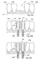
図14aは、算出された咬合線900、インプラント11a〜11fの位置および方向、ならびに6個のインプラント11a〜11f上における12個のユニットのインプラント・ブリッジ・フレームワーク20、さらには自動的に整列された標準的な歯列10a〜10mを示す、上顎骨200の下面図における概略図である。
FIG. 14a shows the calculated
図14bは、被せられたインプラント11dおよびブリッジフレームワーク20を伴った位置番号21の歯における、図14aに示されている平面14bを通る断面図であり、空間位置を有する、インプラント11dとブリッジフレームワーク20とをつなぎ合わせる境界面が示されている。
FIG. 14b is a cross-sectional view through the
上で述べられているように、被止は、咬合線900における、空間位置を持った外側境界面、および被止10gとブリッジフレームワーク20の空間位置を持った外側境界面との間の接続界面210gとして機能する、空間位置を持った内側境界面を有している。同時に、ブリッジフレームワーク20は、インプラント11dに向けて配向されている、空間位置を持ったさらなる境界面を有しており、その境界面はインプラント11dとの接続界面として機能する。インプラント11dは、ブリッジフレームワーク20のさらなる境界面との接続界面215dとして機能する、空間位置を持った最上部の境界面を有している。これらの境界面および接続界面が、図14cに示されている拡大図で描かれている。
As described above, the guard is at the
この段階でインプラントまたは被止の位置を微調節するときには、その歯科修復物の残りの部分の自動適合化が実施される。例えば、デンタルインプラントの位置を手作業で微調節するときには、ブリッジフレームワーク20の対応する境界面を再計算することにより、接続界面215dが自動的に適合化される。さらに、被止の内側境界面に対する接続界面210gにおける、ブリッジフレームワーク20の対向する側での境界面が、手作業により誘導されたそのインプラントの位置の微調節に自動的に適合化される。このようにして、ブリッジ構造が自動的に適合化される。歯科修復物の他の部分の手作業による微調節は、その残りのユニットの境界面における対応する自動的な変更をもたらす。
When fine-tuning the position of the implant or guard at this stage, an automatic adaptation of the rest of the dental restoration is performed. For example, when manually fine-tuning the position of the dental implant, the
図18から図22は、無歯顎患者のケースでの仮想的プランニングをさらに例証している。 18 to 22 further illustrate virtual planning in the case of an edentulous patient.
図18は、斜視図における、仮想的にプランニングされたブリッジフレームワーク20、インプラント11a〜11fおよび咬合線900の概略図である。ブリッジフレームワーク20のカラー225が図18に描かれている。これらのカラー225は、それぞれ、デンタルインプラントの頂面と境を接するように配列されている。それぞれのカラー225の頂面およびデンタルインプラントの頂面は空間位置を有している。組み立てられるときには、これら2つの空間位置は、2つのデンタルユニット間の接続界面において隣接している。さらに、カラー225は軟組織の厚みの調節を提供する。インプラント11a〜11eには、顎骨組織に予め準備された孔にネジ接続で取り付けることができるようにネジ山が設けられている。図18および図19には、仮想的なマーカー211a〜211fがより詳細に示されており、それぞれ、各インプラントの中央長手方向軸を指示している。図20は、拡大斜視図における、図18のブリッジフレームワーク20、インプラント11a、11bおよび咬合線900の詳細を示す概略図である。
FIG. 18 is a schematic view of the virtually planned
図19では、その略図にテンプレート歯列が加えられており、分かりやすくするため、歯10aにのみ参照符号が与えられている。テンプレート歯列は点線で示されている。
In FIG. 19, a template tooth row is added to the schematic diagram, and for ease of understanding, only the
図21は、下から見た斜視図における、図18のブリッジフレームワーク、インプラントおよび咬合線の詳細を示す概略図である。図22では、その略図に仮想的歯列のライブラリーからのテンプレート歯列が加えられており、その歯列が咬合線900との関係においてどのように位置付けされるかが示されている。
21 is a schematic diagram showing details of the bridge framework, implant and occlusal line of FIG. 18 in a perspective view from below. In FIG. 22, a template dentition from a library of virtual dentitions is added to the schematic and how the dentition is positioned in relation to the
150 最終的修復物の概算
図14bは、位置番号2−1(EU)の歯における、ブリッジフレームワーク20および被止を含むブリッジ構造を示している。
150 Approximate Final Restoration FIG. 14b shows the bridge structure including the
図23は、ブリッジフレームワーク20およびテンプレート歯10gを通る出口穴230を示す、顎骨組織200内にデンタルインプラント11dを含んでいる状態で仮想的にプランニングされた歯科修復物を通る断面図である。後に行われるこの歯科修復物の設置の際にブリッジフレームワークをインプラントに取り付ける保持用ネジのアクセスのために使用されるこの出口穴の方向が、仮想的なマーカー231によって指示されている。この仮想的マーカー231はデンタルインプラント11dの長手方向軸に沿って延びており、その仮想的マーカー231の位置は、ユーザ入力により、例えばマーカー231の端に描かれているドットをマウスインタラクションによってドラッグして移動させることなどにより、修正することができる。この例示されているケースでは、図23に示されている出口穴は、自動的にプランニングされ、歯10gの頬側に視覚可能に位置付けられている。ユーザは、審美的な理由により、この出口穴を隠したいと欲する可能性がある。この目的で、ユーザマニピュレーションにより、図24に描かれているような、この歯科修復物の修正された仮想模型をもたらすことができる。
FIG. 23 is a cross-sectional view through a virtually planned dental restoration with a
図24は、図23のデンタルインプラント11dを含む歯科修復物を通る断面図であり、ここでは、デンタルインプラント11dの位置は、出口穴230が歯10gの舌側へ移されるような方法で修正されている。ブリッジフレームワーク20の空間位置および咬合線における歯10gの最上部位置は変更されていない。しかし、インプラント11dは、ここでは、デンタルインプラント11dの長手方向軸に沿った出口穴230が隠れた場所へ移されるように、すなわち、最終的な製作物が患者に埋入され、患者が微笑んだときに、その穴が見えなくなるように、骨組織200内で角度付けられている。インプラント11dの頂面は変更されていないが、骨組織200内におけるその空間位置に対して成された変更が、その新たな状況に対するブリッジフレームワーク設計の自動的な適合化、さらには、対応する被止の自動的な適合化をもたらしている。より正確に言えば、咬合線における歯10gの最上部位置が、第1空間位置が決定される第1境界面を定めている。インプラント11dの頂面は、第2空間位置が決定される第2境界面である。これら2つの固定された境界面の間の歯科被止の設計およびブリッジフレームワークの設計は、他の要件、例えば隣接する歯との距離などを維持しながら、これら2つの境界面間にぴったりと合うように自動的に適合化される。ブリッジ20と歯科被止との間の境界面の空間位置は、上述の第1空間位置および第2空間位置に対して相対的に決定される。
24 is a cross-sectional view through a dental restoration including the
いったんユーザがこれらの変更を確認すると、その歯科修復物およびドリルガイドの製作は、この新しいデータに基づいて行われるであろう。 Once the user confirms these changes, the creation of the dental restoration and drill guide will be based on this new data.
この歯科被止は利用可能なデータから自動的に製作されてよい。 This dental covering may be automatically produced from the available data.
さらに、被止の着色も自動的に行われてよい。種々のセラミック粉末をスクリーン上で仮想的にプランニングすることができる。そのような技術は、2005年9月23日に出願された、本出願と同じ出願人の国際特許出願PCT/SE2005/001406に詳しく説明されており、これをもって、その出願の内容全体が参照により本明細書に組み入れられる。 In addition, the covering may be colored automatically. Various ceramic powders can be virtually planned on the screen. Such techniques are described in detail in the same applicant's international patent application PCT / SE2005 / 001406, filed September 23, 2005, which is hereby incorporated by reference in its entirety. It is incorporated herein.
よって、本システムは、歯科修復物を完全に自動的に生成するために使用することができる。また、特定の患者の状況に合わせた手作業による適合化、歯科修復物構成要素ライブラリーからの選択肢の選定可能化、またはユーザの他の要望が果たされてよい。 Thus, the system can be used to generate a dental restoration completely automatically. Also, manual adaptations to specific patient situations, the possibility of selecting options from a dental restoration component library, or other user demands may be fulfilled.
160 外科用テンプレートの製作
図15は、側面図における、上顎骨200および軟組織210の概略図である。ステップ100を参照しながら上で説明されているように、骨組織および軟組織を含む患者データを取得する方法は、患者の頭蓋顔面部分をMRスキャニングすること、口腔内における軟組織の厚みを決定するために表面プローブを使用すること、適切な閾値化アルゴリズムによってCTスキャンデータから軟組織が抽出されてよいこと、幾つかの入力ソースからの入力データが合わせられていてよいこと、などを含む。上顎骨組織200および軟組織210の描画された図解の例が図15に示されている。この図解されている例では、患者の上顎は無歯である。図15および図16に示されているように、軟組織210は、単一のCTスキャンから決定されてよい。この場合、取得された軟組織と取得されたエアーとの違いに基づいて、軟組織をそのようなCTデータから抽出することができる。
160 Fabrication of Surgical Template FIG. 15 is a schematic view of the
図16は、側面図における、上顎骨200および軟組織210ならびにインプラント・ブリッジ・フレームワーク20の概略図である。ここで、インプラント・ブリッジ・フレームワーク20の設計についての最終的なチェックが仮想的に行われる。ユーザに対して、軟組織210とともに、ブリッジフレームワーク20およびマーカー211a〜211fによってマーキングされたインプラントの位置の視覚化が提示される。ブリッジフレームワーク20は、接続界面を形成しているそれぞれの境界面においてインプラント11a〜11fに境を接している。また、ブリッジフレームワーク20は軟組織にも支えられており、特定の患者の状況に合わせた最終的な修正は、データが非仮想的な歯科的構成要素の製作のために使用される前に、この段階で仮想的に行うことができる。最終的な手作業による修正が行われるときに、外科用テンプレートを製作することができる。
FIG. 16 is a schematic view of the
図17は、上顎骨200およびドリル・ガイド・ボア31を有する外科用テンプレート30の概略図である。外科用テンプレート30は、歯科修復物が公知の方法によって患者の口腔に埋入される歯科的修復処置中に、ドリルガイドとして機能する。この外科用テンプレートは、この段階で利用することができる最終的な歯科修復物データから仮想的にプランニングされる。ドリルを誘導するためのガイドスリーブ32が概略的に描かれている。この外科用テンプレート30のガイドスリーブ32は、軟組織を通じてドリルを患者の顎骨組織内に差し向けるために使用される。ガイドスリーブ32は、関連するデンタルインプラントの仮想的にプランニングされた位置に沿った、ある定められた方向を有している。さらに、ガイドスリーブ32の頂面は、ドリルに対する止め用段部を有するカラーとしても設けられており、また、ドリルによって穿孔された孔に埋入されることとなるデンタルインプラントの頂面からある定められた距離だけ隔たった位置に設けられている。したがって、その孔の深さは、上述の止め用段部に接するまでガイドスリーブ内に進入する適切なドリルを提供することによりコントロールされる。この止め用段部の頂面は境界面である。このようにして、骨組織内においてある定められた配向および位置を有することとなるデンタルインプラントのその後の埋入用に、正確な孔が提供される。
FIG. 17 is a schematic view of a
術前のプランニングが行われるときに、歯科修復物および/またはその術前プランニングに関係した製作物、例えば外科用テンプレートなどの製作が行われてよい。例えば、軟組織表面およびインプラント位置が、外科的なインプラント処置の間に使用されることとなるドリルガイドのための製作データに変換される。 When pre-operative planning is performed, a dental restoration and / or a product related to the pre-operative planning, such as a surgical template, may be made. For example, soft tissue surfaces and implant positions are converted into fabrication data for a drill guide that will be used during a surgical implant procedure.
上で説明されている、自動的な仮想的術前プランニング、または手作業によって微調整された仮想的術前プランニングに基づき、外科用テンプレートが例えばラピッドプロトタイピング技術を用いて作製されてよい。この外科用テンプレートは、歯科修復物がプランニングされた位置で、かつ、プランニングされた配向で固定されることとなる、デンタルインプラントを取り付けるための適切な孔を創出するために、公知の方法で使用される。 Based on the automatic virtual pre-operative planning described above or virtual pre-operative planning fine-tuned manually, a surgical template may be made using, for example, rapid prototyping techniques. This surgical template is used in a known manner to create suitable holes for attaching dental implants where the dental restoration will be secured in the planned position and in the planned orientation. Is done.
ステレオリソグラフィーによって製作される種々の製作物用のデータ、例えば外科用テンプレートのためのデータなどが、STLなどの適切なフォーマットで保存されてよい。STL(Standard Tessellation Language)ファイルは、様々なソフトウェアパッケージによってインポートおよびエクスポートすることができる。STLファイルはラピッドプロトタイピングに特に適している。このフォーマットは、立体模型の表面をラピッドプロトタイピング用の三角形で概算する。歯科修復物および関連する製作物を製作するのに適したSTL以外の他のデータフォーマットが代替的に実施されてよい。ラピッドプロトタイピングはコンピュータ支援設計(CAD)から仮想的な設計を取り込み、それらを尚も仮想的な断面に変換し、その後、その模型が仕上がるまで次々と物理的な空間において各断面を創出する。 Data for various productions produced by stereolithography, such as data for surgical templates, may be stored in a suitable format such as STL. STL (Standard Tessellation Language) files can be imported and exported by various software packages. STL files are particularly suitable for rapid prototyping. This format approximates the surface of a solid model with triangles for rapid prototyping. Other data formats other than STL suitable for making dental restorations and related products may alternatively be implemented. Rapid prototyping takes virtual designs from computer-aided design (CAD), converts them into virtual cross sections, and then creates each cross section in physical space one after another until the model is finished.
このようにして製作された外科用テンプレートは、高い正確度で良好な患者適合性を提供する。 The surgical template thus produced provides good patient compatibility with high accuracy.
170 歯科修復物の製作
本方法のステップ170では、提供されたデータに基づいて歯科修復物が製作される。
170 Making a Dental Restoration In
もしそうすることが望ましい場合には、上述の仮想的プランニングによってもたらされたデータから、物理的な患者模型が製造されてよい。患者模型は、例えば、被止が手作業で果たされることが望ましい場合での、被止用に使用されてよい。患者模型および咬合器の製作は、本出願と同じ出願人によって出願された、スウェーデン特許出願SE0602271−9およびSE0602273−5に記載されており、これらの特許出願は、それらの内容全体が参照により本明細書に組み入れられる。しかし、このステップは、上で説明されている自動的な仮想的プランニングによって提供された利用可能なデータが、術前プランニング、ならびに外科用テンプレートおよび歯科修復物の製作の両方にとって十分な精度をもたらす場合には、省略することができる。 If it is desirable to do so, a physical patient model may be manufactured from the data provided by the virtual planning described above. The patient model may be used for guarding, for example where it is desired that the guarding is accomplished manually. The manufacture of the patient model and the articulator is described in Swedish patent applications SE0602271-9 and SE0602273-5, filed by the same applicant as this application, which are hereby incorporated by reference in their entirety. Incorporated into the specification. However, this step is that the available data provided by the automatic virtual planning described above provides sufficient accuracy for both pre-operative planning and the production of surgical templates and dental restorations. In some cases, it can be omitted.
本方法のステップ170では、歯科修復物が、術前プランニングによってもたらされたデータから直接的に製作される。
In
歯科修復物の被止は従来の方法で行われてよい。この目的で、物理的な患者模型を使用することができる。別の実施形態では、最終的な修復物の設計は上述の方法ステップに基づいて仮想的に行われ、したがって、手作業による被止はもはや必要ではない。 Covering the dental restoration may be done in a conventional manner. For this purpose, a physical patient model can be used. In another embodiment, the final restoration design is virtually done based on the method steps described above, and thus manual protection is no longer necessary.
最後に、歯科修復物が患者に設置される。より正確には、上で述べられているようにして製作された外科用テンプレートが、それぞれがデンタルインプラントを受け入れる1以上の孔を提供するために使用される。その外科用テンプレートが高精度で製作されることにより、デンタルインプラントは顎骨組織に非常に正確にぴったりと嵌まる。このようにして、歯科修復物のための完璧な基礎がもたらされ、この後、その歯科修復物が公知の方法でデンタルインプラントに取り付けられる。 Finally, a dental restoration is installed on the patient. More precisely, a surgical template made as described above is used to provide one or more holes each receiving a dental implant. The surgical template is manufactured with high precision, so that the dental implant fits very accurately and closely into the jawbone tissue. In this way a complete foundation for the dental restoration is provided, after which the dental restoration is attached to the dental implant in a known manner.
上で説明されている方法を用いることにより、石膏模型の鋳造、分割化およびピンニングは何ら必要でない。これは、歯科的修復処置をプランニングおよび実行するときに、より速やかな納期を提供する。 By using the method described above, no casting, segmentation and pinning of the plaster model is necessary. This provides a faster delivery time when planning and performing dental restoration procedures.
このようにして、非常に正確に位置付けされた歯科修復物が、非常に経済的で、かつ、時間を節約する方法で提供される。 In this way, a very accurately positioned dental restoration is provided in a very economical and time-saving manner.
ブリッジフレームワークが完全に自動的にプランニングされ、かつ、製作され得る。 The bridge framework can be planned and produced completely automatically.
幾つかの治療においては、外科用テンプレートすらもはや必要でない。例えば、歯科用作成物に取り付けられることとなる歯冠、ブリッジフレームワークまたはブリッジ構造などのコーピングを製作するときに、そのコーピングは、自動的な仮想的術前プランニングの間の境界面および接続界面の計算に基づいて直接的に製作することができる。 In some treatments, even surgical templates are no longer needed. For example, when making a coping, such as a crown, bridge framework or bridge structure that will be attached to a dental product, the coping is the interface and connection interface during automatic virtual pre-operative planning. It can be produced directly based on the calculation of
別の実施形態においては、部分的に歯の無い患者のための歯科修復物および歯科的修復処置、さらには、対応する製作物が仮想的にプランニングされ、以下では、そのプランニングについて、図25から図30を参照しながら詳細に説明する。 In another embodiment, dental restorations and dental restoration procedures for a partially toothless patient, as well as the corresponding product, are virtually planned, and in the following, the planning is illustrated in FIG. This will be described in detail with reference to FIG.
図25は、患者の顎骨組織256に前もって埋入されているデンタルインプラント250を含む歯科修復物25を通る断面図である。デンタルインプラント250が顎骨組織256内に治癒のために埋入されている。そのデンタルインプラントの位置に関するデータは、例えば適切な医療用イメージング法および/またはデンタルインプラント250の冠状端257を記録する口腔の歯科印象により提供されてよく、および/または恐らくはそのデンタルインプラント250に対して以前に行われたデンタルプランニングから利用可能なデータであってよい。このようにして、デンタルインプラント250の位置が固定され、冠状表面257の位置が歯科修復物25の仮想的プランニング用にロックされる。この場合においては、ブリッジフレームワーク251および被止252の自動的なプランニングは、点線255で示されているような、それらの提案された位置をもたらした。デンタルインプラント250の長手方向軸253に沿って孔が存在している。図25には、修復され、かつ、デンタルインプラント250に固定されるべき歯の配向がどのようにして、ユーザからの入力に基づいて、代替的な位置へ仮想的な方法で動的に修正されるのかが描かれており、例えば対話形式でプランニング線254を例えばマウスによって図25に示されている矢印の向きに引くことにより、代替的な位置へ仮想的な方法で動的に修正する様子が描かれている。この修正は、患者の局所的な歯科的状況を理由としてユーザにより要望され得る。ユーザによるマニピュレーション入力後に再計算された歯科修復物25の結果がブリッジフレームワーク251および被止252の連続した線によって描かれている。デンタルインプラントに向けたその内部の孔の位置は、冠状面257の位置がロックされているため、また、デンタルインプラント250へのブリッジフレームワークもしくはブリッジ構造の取り付けを容易化するため、変更されていない。このようにして、歯科修復物25は、ブリッジフレームワーク251および被止252を含むブリッジ構造の自動的な適合化を伴って仮想的に修正される。
FIG. 25 is a cross-sectional view through a
最終的な接続界面を見出すための手順は、歯科修復物のエレメントの2つの境界面の空間位置を仮想的にモーフィングすることにより制御することができる。次に、図26Aから図26Cを参照しながら、制御されたモーフィングの使用についてより詳細に説明する。モーフィングは、始原物体から目標物体までの一連の中間的な物体を創出するために使用される補間技術であり、この一連の中間的な物体は、始原物体から目標物体へのスムーズな移行が行われるように連続的に変化する。モーフィングは、例えば3次元のピクセルの値を変えることにより、または3次元模型の幾何学的形状を変形し、すべてが明確に定められた3次元物体である中間的な物体を創出することにより、3次元で行われる。このような文脈において、歯科修復物の2つのユニット間の接続界面をモーフィングにより仮想的に最適化することができる。図26Aに、歯科修復物26aが描かれている。この歯科修復物26aは、歯科修復物エレメント260に取り付けられるコーピング261および歯冠262を含む公知の構造を有している。上述の歯科修復物エレメント260は、現存している歯の歯科的作成物(図29参照)またはデンタルインプラントのキャップ(図30C参照)であってよい。図26Aに描かれているように、コーピング261は、歯科修復物エレメント260との第1接続界面261aに内側表面を有しており、また、歯冠262との第2接続界面261bに外側表面を有している。コーピング261の外側表面は第1接続界面261aからあるオフセットを持って位置付けされており、すなわち、第2接続界面261bは、接続界面261aにおいて、歯科修復物エレメント260の外側表面に平行に延びている。第2接続界面261bの幾何学的形状が与えられたとすると、歯冠262の内側表面は、頂点方向で、その第2接続界面261bにおいて、ある定められた幾何学的形状を有している。歯冠262の外側表面は、冠状方向に関しては咬合によって定められる幾何学的拘束条件が内在し、横方向に関しては隣接する歯列によって定められる幾何学的拘束条件が内在する。上述のようなオフセットを持った形態でコーピングを提供することにより、歯冠262のポーセレンは、このコーピング261によって最適な状態では支持され得ず、歯冠262に不規則に分布した咀嚼応力が加わる状態をもたらす。
The procedure for finding the final connection interface can be controlled by virtually morphing the spatial position of the two interfaces of the dental restoration element. The use of controlled morphing will now be described in more detail with reference to FIGS. 26A-26C. Morphing is an interpolation technique that is used to create a series of intermediate objects from a source object to a target object, which provides a smooth transition from the source object to the target object. Change continuously. Morphing, for example, by changing the value of a three-dimensional pixel or by deforming the geometric shape of a three-dimensional model to create an intermediate object that is a well-defined three-dimensional object, Done in three dimensions. In such a context, the connection interface between two units of a dental restoration can be virtually optimized by morphing. In FIG. 26A, a
この状況は、歯冠262の外側表面に向けて第2接続界面261bをモーフィングすることにより改善することができ、この様子が図26Bに描かれている。この歯科修復物26bは、改善された第2接続界面263bを有している。始原物体が第2接続界面261bであり、かつ、目標物体が歯冠262の外側表面であるとしてモーフィング技術を用いることにより、それらの間でスムーズな移行が形成されるように一連の中間的な物体が算出される。この改善された第2接続界面263bは、歯冠264に一層良好な支持を提供する、モーフィングプロセスにおける中間的な物体のうちの1つとして選択される。歯冠264は、その改善された第2接続界面263bと適合する内側表面を有している。歯冠264の外側表面は、口腔内における周囲の構造物の同一の要件により、または提案された修復物を修正することにより、尚も定められる。
This situation can be improved by morphing the
図26Cでは、歯科修復物エレメント265の外形がそのようなモーフィング技術によって定められており、それにより、別のコーピングが省かれている。より詳細には、歯科修復物エレメント260の冠状外側表面が歯冠262の外側表面に対してモーフィングされ、歯冠266のより有利な支持をもたらすことができるように、ある中間的物体の形状が選択される。このようにして、単一の接続界面265bが定められ、改善された歯科修復物エレメント265および歯冠266が提供される。
In FIG. 26C, the outline of the
どのような場合においても、接続界面を決定するときには、最小限の材料強度が保有されていることを観察すべきである。仮想的歯列ライブラリーにおける上述のテンプレート歯列は、例えばテンプレート歯の任意の点において予め定められた最小材料厚みを有することにより、そのようなマニピュレーションを許容すべく適合化させることができる。 In any case, it should be observed that a minimum material strength is retained when determining the connection interface. The template dentition described above in the virtual dentition library can be adapted to allow such manipulation, for example by having a predetermined minimum material thickness at any point of the template tooth.
別の実施形態においては、他の歯科修復物エレメント、例えばブリッジフレームワークが、モーフィング技術によって最適化されてよく、または定められてよい。モーフィングと類似の技術がワーピングとして知られている。 In another embodiment, other dental restoration elements, such as a bridge framework, may be optimized or defined by morphing techniques. A technique similar to morphing is known as warping.
図27A〜27Cは、2本の歯を欠いている患者の概略図である。歯が2本抜けている位置において、この患者の歯列弓にギャップ271が形成されている。残っているのは歯270a〜dである。図27Bには、2つのインプラント274a、274b、ブリッジフレームワーク273aおよび被止272aを含む、自動的にプランニングされた歯科修復物27aの提案が描かれている。ブリッジフレームワーク273aおよび被止272aは、それぞれ、デンタルインプラント274aおよび275aに設置するための2つの孔276、277を有している。この歯科修復物27aの自動的にプランニングされた提案は、患者の歯列弓に沿ったギャップ271を充填するため、ならびにその歯列弓に残っている歯から算出された咬合線および場合によってはさらに解剖学的に固定された基準点をも利用して算出された咬合線にぴったりと適合させるための、歯列ライブラリーからの2本のテンプレート歯列をベースとしている。患者の局所的な状況により、または審美的な理由から、歯科修復物27aの上述の提案されたプランニングを手作業によって調整することが望まれる場合があり得よう。これは、例えば審美的な理由によるものであり得る。幾つかの実施形態においては、ギャップ271がそこにあるライブラリー歯列を自動的にインターフィッティングさせるときに許容するものよりもより大きな歯列を有することが望まれてよい。手作業で修正されたプランニングの結果が図27Cに示されており、この図は、調整されたデンタルインプラント274b、275b、調整されたブリッジフレームワーク273bおよび被止272bを含む、修正済みの仮想的にプランニングされた歯科修復物27bを示している。自動的にプランニングされ、かつ、提案された歯科修復物27aの手作業により修正された位置は、上述の自動的にプランニングされた歯科修復物27aの提案によって提供されるテンプレート歯列のスケーリングに基づくものであってよい。あるいは、またはさらに、手作業により修正される位置は、その歯列ライブラリーからの、異なるサイズの、より大きなまたはより小さなテンプレート歯列に基づくものであってよい。これらの適合化されたブリッジフレームワーク273b、被止272bおよびインプラント274b、275bは、調整された歯科修復物27bの所望の修正された位置および伸展についてのユーザ入力に基づいて自動的に選ばれてよい。固定されているロックされた表面は、隣接する歯列270aおよび270cの外側表面である。その歯列弓の咬合線を越えて仮想的歯列を移動させるときには、自動的なプランニングでは、患者にとって快適な咬合がもたらされるように、対向する顎に存在すると考えられる歯列を考慮に入れる。
27A-27C are schematic views of a patient lacking two teeth. A
残っている歯の歯科矯正または外科的矯正およびそのような矯正された歯列位置に対する歯科修復物の自動的な適合化を可能にする診断が与えられてよい。解剖学的に固定された基準点から自動的に算出された歯列の位置に基づいて、歯科修復物を伴うことなく、残っている歯の歯科矯正または外科的矯正を行うこともできる。 A diagnosis may be given that allows orthodontic or surgical correction of the remaining teeth and automatic adaptation of the dental restoration to such corrected dentition position. Based on the position of the dentition automatically calculated from the anatomically fixed reference points, orthodontic or surgical correction of the remaining teeth can be performed without a dental restoration.
図28は、患者の下顎の歯列弓28の概略図である。解剖学的に現存している歯列280が連続的な線で描かれている。これらの解剖学的に現存している歯列280の位置に関するデータは上述されている方法によって与えられてよく、そのような方法は、例えば医療用イメージング法、3Dデータへ変換される歯科トレー印象または口腔内3Dスキャニング法を意味する。このデータに基づき、その患者の解剖学的に現存している歯列280との関係において仮想的にプランニングされた歯列281の自動的に提案される位置を算出することができる。仮想的にプランニングされた歯列281は点線で示されている。医療用ワークステーションのデータモニタ上でこの状況を視覚化することにより、解剖学的に現存している歯列280の不規則性を矯正するためのプランニングが可能になる。ここで描かれている非限定的な例では、犬歯284、285に隣接した2本の小臼歯282、283が、仮想的にプランニングされた歯列281の自動的に提案された位置から実質的にずれている。このズレは、その患者の歯科的状況およびそれを矯正することができる可能性についての迅速な評価を可能にするため、視覚化することを目的としてカラー符号化されてよい。この分析に基づき、歯科的矯正をプランニングすることができる。その歯科的矯正は、現存している歯列の外科的抜歯および/または特定の歯列の位置の歯列矯正的管理を含み得る。仮想的にプランニングされた歯列281の提案された位置によって誘導される、解剖学的に現存している歯列280の表示を動かすことにより、歯科的修復処置を仮想的にプランニングすることができる。ユーザは、歯列の位置を、例えば1つずつ、ロックすることができる。歯科修復物がこの歯科的状況の矯正のためにプランニングされる場合においては、例えば隣接している歯列および咬合のロックされた表面に基づいて、これらを自動的に算出することができる。その歯科的状況の所望の矯正が仮想的にプランニングされるときには、デンタルインプラント、ブリッジフレームワーク、被止またはコーピングおよび歯冠の位置が自動的に算出されてよい。このようにしてもたらされたデータが、上で説明されているように、歯科修復物およびそれに関連する製作物を製作するために使用されてよい。ユーザによるそのプランニングの最終的な応諾の前に、それらの歯科修復物の手作業による修正が行われてよい。
FIG. 28 is a schematic view of a patient's lower
図29は、患者の解剖学的に現存している歯290の作成に基づいて仮想的にプランニングされた歯科修復物29の概略図である。2本の歯292、293に隣接している歯290が、図29の上側の図で描かれているようにして作成される。このようにして、歯290に、歯科修復物を取り付けるための準備表面291が設けられる。その歯科修復物を仮想的にプランニングするためのデータが、例えば3Dスキャニングされる歯科印象または口腔内スキャナにより提供される。歯科修復物29の自動的なプランニングにおいては、隣接している歯292、293の表面と同様に準備表面291もロックされる。さらに、上で説明されているようにして、解剖学的に固定された基準点から、または場合によっては咬合指数から決定することができる咬合線もロックされてよい。あるいは、有利な咬合を持つ、仮想的にプランニングされた歯科修復物をもたらすために、仮想的咬合器が用いられてもよい。これらのロックされた表面に基づき、歯科修復物がプランニングされる。被止295の外側表面はロックされた表面によりもたらされる拘束条件に基づいて決定される。中間的なコーピング294は、それぞれ、作成物および被止に向けた接続界面から自動的に算出される。この中間的なコーピングは、上で説明されているように、モーフィングによって最適化することができる。この自動的にプランニングされた歯科修復物29は、医療用ワークステーションを用いて、ユーザにより手作業で修正されてよい。あるいは、仮想的にプランニングされたその歯科修復物29が、ユーザの承認を伴わずに直接的に製作されてもよい。この後、その製作された歯科修復物は、公知の方法により、例えば歯科用セメントまたは歯科接着法を用いることにより、歯290の作成物に付着されてよい。
FIG. 29 is a schematic diagram of a
図30Aは、歯300を抜歯した後に、顎骨組織308内にデンタルインプラントを埋入する様子の概略図である。歯300の抜歯は、2本の隣接している歯301、302の間にギャップ303を残す。歯300の抜歯後、ギャップ303が顎骨組織308内に延びている。デンタルインプラント305を埋入するため、ドリルガイド304により、その位置に孔が設けられてよい。デンタルインプラントにはヒーリングキャップ306が設けられていてよく、ヒーリングキャップは、抜歯部位の治癒時における歯肉の同時形成を伴った、周辺軟組織の正確な肥厚をもたらす。図30Aの最も下側の図では、インプラント307は、その後の治癒期の間に形成された新骨組織307とともにオッセオインテグレーションされている。この段階で、インプラント307は、完結的な歯科修復物の仮想的なプランニングを行う準備が整っており、その仮想的なプランニングについては以下で図30Cを参照しながら説明する。
FIG. 30A is a schematic view of a dental implant placed in the jawbone tissue 308 after the
図30Bは、隣接している歯315、316の間の歯のギャップ310の位置における、治癒した顎骨組織314でのデンタルインプラント312の埋入の様子の概略図である。その位置が、ギャップ310に隣接している歯列315、316により調節され得る、または軟組織により支持され得る、ドリルガイド311により、デンタルインプラント312を受け入れるための孔が設けられてよい。あるいは、またはさらに、軟組織の形態またはトポグラフィが、製作の間にドリルガイドの内側を形成するためのデータを供給するために使用されてもよい。このデンタルインプラント312にはヒーリングキャップ313が設けられていてよい。図30Bの最も下側の図では、インプラント313が骨組織314とオッセオインテグレーションされている。この段階で、インプラント307は、完結的な歯科修復物の仮想的なプランニングを行う準備が整っている。
FIG. 30B is a schematic illustration of the placement of a
図30Cは、患者の生体構造に既に存在しているデンタルインプラント320を考慮に入れた、歯科修復物の仮想的なプランニングの概略図である。デンタルインプラント320は、隣接している歯列322、323の間のギャップ321において、患者の顎骨組織327内に与えられている。デンタルインプラント320上に間隔部324が配列されていてよい。歯科修復物30の仮想的プランニングのためのデータが、例えば3Dスキャニングされる歯科印象により、上で指示されているようにして与えられる。デンタルインプラント320または間隔部324の頂面は最終的なものであり、プランニング中に修正することはできず、すなわち、その頂面は仮想的プランニングではロックされている。
FIG. 30C is a schematic diagram of a virtual planning of a dental restoration taking into account the
頭蓋口腔内の現存している解剖学的構造物、歯列、デンタルインプラントまたは他の歯科修復物は、表面同定法により、歯科修復物の自動的プランニングにおける考察のために同定することができる。例えば、現存しているデンタルインプラントは、その特徴的な形状または寸法により、歯科印象からのデータにおいて同定することができる。あるいは、例えばCTスキャンの取得されたHounsfield値の密度閾値化が、頭蓋口腔スペースの患者データにおける対象物の同定に役立ち得る。例えば軟組織および骨組織または歯へのセグメンテーションが、そのような対象物を模型化するために行われてよい。解剖学的に現存している物体が同定されるときに、歯科修復物の仮想的プランニングのためにそれらの外側表面がロックされてよい。一方、自動的な仮想的プランニングではこれらのロックされた表面を考慮に入れる。例えば、デンタルインプラントとの接続界面における歯科用ブリッジフレームワークの外形が、そのデンタルインプラントの対応するロックされた頂面と適合するように自動的に形作られ得る。あるいは、再構成される歯の頂面が最終的な空間位置にあるべきことも決定されているときには、その歯科用ブリッジフレームワークの頂面が被止の対応する内側表面と適合するように自動的に形作られてもよい。 Existing anatomical structures, dentitions, dental implants or other dental restorations in the cranial oral cavity can be identified for consideration in automatic planning of dental restorations by surface identification methods. For example, existing dental implants can be identified in data from dental impressions by their characteristic shape or dimensions. Alternatively, density thresholding of acquired Hounsfield values of, for example, a CT scan can help identify objects in patient data of the cranial oral space. For example, segmentation into soft tissue and bone tissue or teeth may be performed to model such objects. When anatomically existing objects are identified, their outer surfaces may be locked for virtual planning of dental restorations. On the other hand, automatic virtual planning takes these locked surfaces into account. For example, the profile of the dental bridge framework at the connection interface with the dental implant can be automatically shaped to match the corresponding locked top surface of the dental implant. Alternatively, when it has also been determined that the top surface of the reconstructed tooth should be in the final spatial position, the top surface of the dental bridge framework is automatically adapted to match the corresponding inner surface of the guard. May be shaped.
図30Cに戻って説明すると、歯科修復物30は、デンタルインプラント320またはそれに取り付けられた間隔部の頂面上にぴったりと適合するように自動的に仮想的にプランニングされる。再構成される歯の外形、ここでは歯冠326の外形は、現存している近隣の歯322、323および所望の咬合、すなわち、歯冠326の最も上側の冠状位置との関係で決定される。これらの拘束条件に基づいて、コーピングが、歯冠の内側表面とデンタルインプラント320または間隔部324の頂面との間で整合的にぴったりと適合するように自動的に形作られる。歯冠326の内側表面における接続界面は、歯科修復物30の構造強度要件が有利に満たされるように設計されてよい。
Returning to FIG. 30C, the
要約すると、ほぼ完成状態の製作品または完成状態の製作品が、上で説明されている本自動的プランニング法によるデータに基づいて提供され得る。この仮想的プランニング中に動的修正を行うことができ、これにより、解剖学的に現存している歯列または歯科修復物が考慮される。ほぼ完成状態の製作品は、例えば歯科技工士が手作業でその歯科修復物の最終的な被止を製作することができるデンタルインプラントおよび関連する歯科用ブリッジフレームワークである。完成状態の製作品を提供するときには、被止さえもが自動的に提供され得る。さらに、仮想的にプランニングされ、かつ、製作された歯科修復物を挿入する際に必要な器具も製作されてよい。例えば、ドリルで孔を開けるための外科用テンプレート、さらには、対応するドリルを製作することができる。 In summary, a near-finished product or a finished product can be provided based on the data from the automatic planning method described above. Dynamic modifications can be made during this virtual planning, thereby taking into account anatomically existing dentitions or dental restorations. A near-finished product is, for example, a dental implant and associated dental bridge framework that allows a dental technician to manually create the final guard of the dental restoration. When providing a finished product, even a guard can be provided automatically. In addition, the appliances required to insert a virtually planned and manufactured dental restoration may be produced. For example, a surgical template for drilling holes can be produced, as well as a corresponding drill.
上で説明されている方法を実施するためのシステムに関する一実施形態が図31に概略的に描かれている。 One embodiment of a system for performing the method described above is schematically depicted in FIG.
システム1900は、頭蓋口腔スペースを有する患者の歯科的修復処置の、および/またはその歯科的修復処置のための少なくとも1つの歯科的構成要素の、コンピュータベースのプランニングを提供する。このシステム1900は、歯科修復物の第1デンタルユニットの、前述の頭蓋口腔スペース内における、第1境界面の第1空間位置を決定するための第1ユニット1922と、その歯科修復物の第2デンタルユニットの、前述の第1境界面から隔たった位置の上述の頭蓋口腔スペース内における、第2境界面の第2空間位置を決定するための第2ユニット1924と、前述の第1空間位置および第2空間位置のうちの少なくとも一方に対して相対的な、前述の歯科的構成要素のうちの少なくとも一部の第3空間位置を決定するための第3ユニットと、を有している。
医療用ワークステーション1910は、中央演算処理装置(CPU)1920、メモリおよびインターフェースなどの通常のコンピュータ構成要素を備えている。さらに、データ入力ソースから受け取ったデータ、例えばCTスキャニングまたは3Dスキャニングから得られたデータなどを処理するための適切なソフトウェアも備えている。そのソフトウェアは、例えば医療用ワークステーション1910によってアクセス可能なコンピュータ可読媒体1930に保存されていてよい。そのコンピュータ可読媒体1930は、患者の歯科的修復処置をプランニングするため、およびその歯科的修復処置に関係した歯科的構成要素をプランニングするために、適切なコードセグメント190、191を含むコンピュータプログラム1940の形態で、そのソフトウェアを含んでいてよい。医療用ワークステーション1910は、さらに、例えば視覚化された内容を表示させるためのモニタ、ならびに、例えばその自動的プランニングさもなければ上述のソフトウェアによって提供されたプランニングを手作業により微調節するためのキーボードおよびマウスなどの、適切なヒューマンインターフェース装置を含む。医療用ワークステーションは、患者の歯科的修復処置をプランニングするための、さらには、それに関係する歯科的構成要素をプランニングするための、システム1900の一部であってよい。また、医療用ワークステーションは、歯科修復物および上述の歯科的修復処置に関係した製作物のうちの少なくとも1つを製作するためのデータも提供してよい。
The
プランニングする際には、例えばCTスキャンからの患者データが、例えば医療用ワークステーション1910上で実行される歯科的修復処置の術前プランニングのためのソフトウェアにインポートされる。その医療用ワークステーション1910は、頭蓋口腔スペースを有する患者の歯科的修復処置および/またはその歯科的修復処置のための少なくとも1つの歯科的構成要素のコンピュータベースのプランニングを行うためのグラフィカル・ユーザ・インターフェースを有していてよい。また、グラフィカル・ユーザ・インターフェースは、本明細書において以上で説明されている方法または添付の特許請求項で記載されている方法を視覚化するための構成要素を含んでいてよい。
In planning, for example, patient data from a CT scan is imported into software for preoperative planning of a dental restoration procedure performed on, for example, a
術前プランニングが行われるときに、歯科修復物および/または前述の術前プランニングに関係した製作物、例えば外科用テンプレートなどの製作が行われてよい。一実施形態においては、コンピュータプログラム1940は、頭蓋口腔スペースを有する患者の歯科的修復処置および/またはその歯科的修復処置のための少なくとも1つの歯科的構成要素、例えばブリッジフレームワーク、被止および外科用テンプレートなどのコンピュータベースのプランニングに有用である。このコンピュータプログラムは、歯科修復物の、例えば被止、ブリッジフレームワークまたはデンタルインプラントなどの第1デンタルユニットの、その患者の頭蓋口腔スペース内における第1境界面の第1空間位置を決定するための第1コードセグメント190を含んでいる。第2コードセグメント191は、その歯科修復物の第2デンタルユニットの、第1境界面から隔たった場所に位置付けされている第2境界面の第2空間位置を決定するために提供されている。第2デンタルユニットは上述の第1デンタルユニットとは異なっており、被止、ブリッジフレームワークまたはデンタルインプラントを含んでいてよい。コンピュータプログラムは、さらに、前述の第1空間位置および第2空間位置のうちの少なくとも一方に対して相対的な、上述の歯科的構成要素のうちの少なくとも一部の第3空間位置を決定するための第3コードセグメントを含んでいてよい。その歯科的構成要素は、例えば被止、ブリッジフレームワークもしくはデンタルインプラント、または外科用テンプレートであってよい。例えば、上述の第1空間位置は咬合線における歯の頂面の空間位置であり、第2空間位置はデンタルインプラントの頂面の空間位置であり、そして、第3空間位置はブリッジフレームワークと被止との間の接続界面の空間位置である。コンピュータプログラムは、本明細書において以上で説明されている方法または添付の特許請求項に記載されている方法の実行を可能にするものであってよい。また、コンピュータプログラムがコンピュータ可読媒体上で具体化されてよい。上で述べられているように、コンピュータプログラムは、医療用ワークステーションまたは仮想的な計算および設計用途に適した類似の計算装置で実行されてよい。
When pre-operative planning is performed, production of dental restorations and / or artifacts related to the aforementioned pre-operative planning, such as surgical templates, may be performed. In one embodiment, the
本明細書で使用する場合、単数形態「a」、「an」および「the」は、そうでないことが明確に示されていない限り、複数形態をも包含する。さらに、本明細書で使用する場合、用語「含む(includes/comprises)」、「含んでいる(including/comprising)」は、記載した特徴、整数、ステップ、操作、要素、および/またはコンポーネントの存在を明記するが、1つまたはそれ以上の他の特徴、整数、ステップ、操作、要素、コンポーネント、および/またはそれらの群の存在または追加を排除するものではないことが理解されるであろう。ある要素が、他の要素に「結合される(connected)」または「連結される(coupled)」と示される場合、それは他の要素に直接的に結合または連結されることができ、あるいは、介在要素が存在することができることは理解されるであろう。さらに、本明細書で使用される場合、「結合される」または「連結される」は、ワイヤレスで結合または連結されることも包含することができる。本明細書で使用する場合、用語「および/または」は、関連する列挙された項目の1つまたはそれ以上の組合せのいずれかおよび全てを包含する。 As used herein, the singular forms “a”, “an”, and “the” include plural referents unless the content clearly dictates otherwise. Further, as used herein, the terms “includes / comprises”, “including / comprising” are the presence of the described feature, integer, step, operation, element, and / or component. It will be understood that this does not exclude the presence or addition of one or more other features, integers, steps, operations, elements, components, and / or groups thereof. When an element is indicated as “connected” or “coupled” to another element, it can be directly coupled or linked to another element, or intervened It will be appreciated that elements can be present. Further, as used herein, “coupled” or “coupled” can encompass wirelessly coupled or coupled. As used herein, the term “and / or” includes any and all combinations of one or more of the associated listed items.
当業者には理解される通り、本発明は装置、システム、方法、またはコンピュータプログラム製品として具現することができる。したがって本発明は、完全なハードウェア実施形態、ソフトウェア実施形態、またはソフトウェア態様およびハードウェア態様を組み合わせた実施形態の形を取ることができる。 As will be appreciated by one skilled in the art, the present invention may be embodied as an apparatus, system, method, or computer program product. Accordingly, the present invention can take the form of an entirely hardware embodiment, a software embodiment or an embodiment combining software and hardware aspects.
さらに本発明は、媒体に埋め込まれたコンピュータ使用可能プログラムコードを有する、コンピュータ使用可能記憶媒体上のコンピュータプログラム製品の形を取ることができる。ハードディスク、CD‐ROM、光学記憶装置、インターネットもしくはイントラネットをサポートするような伝送媒体、または磁気記憶装置をはじめ、いずれかの適切なコンピュータ可読媒体を利用することができる。 Furthermore, the present invention can take the form of a computer program product on a computer-usable storage medium having computer-usable program code embedded in the medium. Any suitable computer readable medium may be utilized including hard disks, CD-ROMs, optical storage devices, transmission media that support the Internet or Intranet, or magnetic storage devices.
本発明の実施形態を本書では、フローチャートおよび/またはブロック図を参照しながら説明している。図示したブロックの一部または全部をコンピュータプログラム命令によって実現することができることは理解されるであろう。これらのコンピュータプログラム命令は、汎用コンピュータ、専用コンピュータのプロセッサ、または他のプログラマブルデータ処理装置に提供され、コンピュータのプロセッサまたは他のプログラマブルデータ処理装置を介して実行される命令が、フローチャートおよび/またはブロック図の単一または複数のブロックに指定された機能/活動を実現するための手段を形成するように、機械を製作することができる。 Embodiments of the present invention are described herein with reference to flowchart illustrations and / or block diagrams. It will be understood that some or all of the illustrated blocks can be implemented by computer program instructions. These computer program instructions are provided to a general purpose computer, a processor of a special purpose computer, or other programmable data processing device, and instructions executed via the computer processor or other programmable data processing device are flowcharts and / or blocks. The machine can be fabricated to form a means for implementing the functions / activities specified in the single or multiple blocks of the figure.
これらのコンピュータプログラム命令はまた、コンピュータ可読メモリに格納された命令がフローチャートおよび/またはブロック図の単一または複数のブロックに指定された機能/活動を実現する命令手段を含む製品を製作するように、コンピュータまたは他のプログラマブルデータ処理装置に特定の仕方で機能するように支持することのできるコンピュータ可読メモリに格納することもできる。コンピュータプログラム命令はまた、コンピュータまたは他のプログラマブル装置で実行された命令がフローチャートおよび/またはブロック図の単一または複数のブロックに指定された機能/活動を実現するためのステップをもたらすように、コンピュータまたは他のプログラマブルデータ処理装置にロードして、一連の動作ステップをコンピュータまたは他のプログラマブル装置で実行させて、コンピュータ実現プロセスを生じさせることもできる。 These computer program instructions also produce a product that includes instruction means for the instructions stored in the computer readable memory to implement the functions / activities specified in the single and multiple blocks of the flowcharts and / or block diagrams. It can also be stored in a computer readable memory that can be supported to function in a particular manner on a computer or other programmable data processing device. The computer program instructions may also be such that instructions executed on the computer or other programmable device provide steps for implementing the functions / activities specified in the single and multiple blocks of the flowcharts and / or block diagrams. Or it can be loaded into other programmable data processing devices and a series of operational steps can be performed on a computer or other programmable device to create a computer-implemented process.
図において示された機能/活動が、操作上の実例において示された順と異なって行なわれることができることは理解されるべきである。例えば、連続して示される2つのブロックは、含まれる機能/活動に依存して、実際は、実質的に同時に実行されることができるか、または2つのブロックはしばしば逆の順で実行されることができる。図のうちのいくつかは、伝達の主たる方向を示すために伝達経路上に矢印を含むが、伝達が描かれた矢印と反対の方向にも起こりうることは理解されるべきである。 It should be understood that the functions / activities shown in the figures can be performed differently from the order shown in the operational examples. For example, two blocks shown in succession can actually be executed substantially simultaneously, depending on the function / activity involved, or the two blocks are often executed in reverse order Can do. Some of the figures include arrows on the transmission path to indicate the main direction of transmission, but it should be understood that transmission can also occur in the opposite direction to the depicted arrow.
本発明を特定の実施形態に関連して上述した。しかし、上記以外の実施形態も本発明の精神および範囲内で同等に可能である。ハードウェアまたはソフトウェアによって当該方法を実行する、上記とは異なる方法ステップを、本発明の精神および範囲内で提供することができる。本発明の異なる特徴およびステップを、記載したものとは異なる組合せで組み合わせることができる。本発明の範囲は、付属の特許請求の範囲によってのみ限定される。 The present invention has been described above with reference to specific embodiments. However, other embodiments than the above described are equally possible within the spirit and scope of the invention. Different method steps than those described above, performing the method by hardware or software, can be provided within the spirit and scope of the invention. Different features and steps of the invention may be combined in different combinations than those described. The scope of the invention is limited only by the appended claims.
Claims (17)
前記歯科的修復処置のためのブリッジフレームワークのコンピュータベースのプランニング
のための方法であって、
前記患者から得られた頭蓋口腔データセットにおける解剖学的に安定な少なくとも1つの解剖学的に固定された基準点を同定し、次に前記少なくとも1つの解剖学的に固定された基準点から、仮想歯および咬合線のうちの少なくとも1つの空間における位置を決定することによって、歯科修復物の被止の、前記頭蓋口腔スペース内における、第1境界面の第1空間位置を決定するステップと、ただし、前記第1境界面は、前記患者の前記咬合線に冠状的に配列される、
前記歯科修復物のデンタルインプラントの、前記第1境界面から隔たった位置の前記頭蓋口腔スペース内における、第2境界面の第2空間位置を決定するステップと、ただし、前記デンタルインプラントの上面は、前記第2境界面である、
前記第1空間位置および第2空間位置のうちの少なくとも1つに対して相対的な、前記ブリッジフレームワークの少なくとも一部の第3空間位置をコンピュータを介して決定するステップと
を含む方法。 Bridge Framework computer-based planning for dental repair computer-based planning of treatment and the dental restorative treatments for patients with cranial oral space
A method for
Identifying at least one anatomically stable reference point in the cranio-oral dataset obtained from the patient, and then from the at least one anatomically fixed reference point, by determining the position in at least one space of the virtual tooth and occlusion line, and determining of the stop of the dental restoration, in the cranial intraoral space, a first spatial position of the first boundary surface, However, the first interface is coronally arranged on the occlusal line of the patient,
Determining a second spatial position of a second interface in the cranial oral space at a position spaced from the first interface of the dental implant of the dental restoration, wherein the upper surface of the dental implant is: The second boundary surface;
Determining via a computer a third spatial position of at least a portion of the bridge framework relative to at least one of the first spatial position and the second spatial position.
前記第1接続界面を最終的な第1接続界面として確立するステップと、
前記最終的な第1接続界面に対して相対的な前記第3空間位置を決定するステップと、
前記第2接続界面を最終的な第2接続界面として確立するステップと
を含む、請求項4に記載の方法。 Determining the second spatial position as its final spatial position ;
Establishing the first connection interface as a final first connection interface;
Determining the third spatial position relative to the final first connection interface ;
And establishing the second connection interface as a final second connection interface method of claim 4.
前記解剖学的に固定された基準点から、前記第1空間位置および第2空間位置のうちの1つを有する少なくとも1本の歯の空間における位置を決定するステップと
をさらに含む、請求項1に記載の方法。 Identifying at least three anatomically stable reference points in the cranial oral data set obtained from said patient;
From the anatomically fixed reference points, further comprising the step of determining the position in at least one tooth space having one of said first spatial position and a second spatial position, claim 1 the method according to.
Applications Claiming Priority (3)
| Application Number | Priority Date | Filing Date | Title |
|---|---|---|---|
| SE0701296 | 2007-05-25 | ||
| SE0701296-6 | 2007-05-25 | ||
| PCT/EP2008/004072 WO2008145293A2 (en) | 2007-05-25 | 2008-05-21 | Method and system for dental planning |
Publications (2)
| Publication Number | Publication Date |
|---|---|
| JP2010527667A JP2010527667A (en) | 2010-08-19 |
| JP5427778B2 true JP5427778B2 (en) | 2014-02-26 |
Family
ID=39769405
Family Applications (1)
| Application Number | Title | Priority Date | Filing Date |
|---|---|---|---|
| JP2010508735A Expired - Fee Related JP5427778B2 (en) | 2007-05-25 | 2008-05-21 | Method and system for dental planning |
Country Status (8)
| Country | Link |
|---|---|
| US (1) | US8425229B2 (en) |
| EP (1) | EP2156350A1 (en) |
| JP (1) | JP5427778B2 (en) |
| KR (1) | KR101380771B1 (en) |
| CN (1) | CN102084365B (en) |
| AU (1) | AU2008256518B2 (en) |
| BR (1) | BRPI0811883A2 (en) |
| WO (1) | WO2008145293A2 (en) |
Families Citing this family (68)
| Publication number | Priority date | Publication date | Assignee | Title |
|---|---|---|---|---|
| US8751031B2 (en) * | 2004-02-06 | 2014-06-10 | Zircore, Llc | System and method for mass custom manufacturing of dental crowns and crown components |
| US20100035212A1 (en) * | 2008-08-11 | 2010-02-11 | Jean Robichaud | Preparation of dental implant surgery and prosthesis installation |
| ES2447941T3 (en) | 2009-02-26 | 2014-03-13 | Nobel Biocare Services Ag | Dental implant set |
| EP2229914B1 (en) | 2009-03-20 | 2018-05-30 | Nobel Biocare Services AG | System and method for aligning virtual models |
| EP3593755B1 (en) * | 2009-03-20 | 2021-08-18 | 3Shape A/S | Computer program product for planning, visualization and optimization of dental restorations |
| EP2254068B1 (en) | 2009-05-18 | 2020-08-19 | Nobel Biocare Services AG | Method and system providing improved data matching for virtual planning |
| EP2322114A1 (en) | 2009-11-16 | 2011-05-18 | Nobel Biocare Services AG | System and method for planning a first and a second dental restoration |
| EP2322115B1 (en) | 2009-11-16 | 2017-02-15 | Nobel Biocare Services AG | Method for planning and producing a dental prosthesis |
| EP2324795A1 (en) * | 2009-11-19 | 2011-05-25 | 3M Innovative Properties Company | A method and system for designing a dental restoration |
| EP2536347B1 (en) * | 2010-02-19 | 2018-12-05 | 3Shape A/S | Method of composing and designing a set of teeth |
| US9179988B2 (en) | 2010-05-25 | 2015-11-10 | Biocad Medical, Inc. | Dental prosthesis connector design |
| GB201009999D0 (en) * | 2010-06-15 | 2010-07-21 | Materialise Dental Nv | Custom healing cap for dental implantology and method for design and manufacturing thereof |
| US8949730B2 (en) * | 2010-07-14 | 2015-02-03 | Biocad Medical, Inc. | Library selection in dental prosthesis design |
| DE102010036841A1 (en) * | 2010-08-04 | 2012-02-09 | Charité - Universitätsmedizin Berlin | Method for generating a digital tooth topology for a tooth structure and measuring method |
| US9226806B2 (en) | 2010-09-17 | 2016-01-05 | Biocad Medical, Inc. | Occlusion estimation in dental prosthesis design |
| US9566138B2 (en) | 2010-10-01 | 2017-02-14 | Rune Fisker | Modeling and manufacturing of dentures |
| US8954181B2 (en) * | 2010-12-07 | 2015-02-10 | Sirona Dental Systems Gmbh | Systems, methods, apparatuses, and computer-readable storage media for designing and manufacturing custom dental preparation guides |
| EP2663254B1 (en) * | 2011-01-13 | 2020-07-29 | Align Technology, Inc. | Methods, systems and accessories useful for procedures relating to dental implants |
| WO2013053903A1 (en) * | 2011-10-12 | 2013-04-18 | 3Shape A/S | Method of globally designing a set of teeth |
| WO2013092744A1 (en) * | 2011-12-21 | 2013-06-27 | 3Shape A/S | Virtually designing a customized healing abutment |
| WO2013120955A1 (en) | 2012-02-14 | 2013-08-22 | 3Shape A/S | Modeling a digital design of a denture |
| JP2013169239A (en) * | 2012-02-17 | 2013-09-02 | Gikou:Kk | Dental prosthesis manufacturing support device and program thereof, and tooth form data |
| WO2013186315A2 (en) * | 2012-06-15 | 2013-12-19 | Vita Zahnfabrik H. Rauter Gmbh & Co. Kg | Method for preparing a partial or full dental prothesis |
| GB201216230D0 (en) | 2012-09-12 | 2012-10-24 | Nobel Biocare Services Ag | An improved surgical template |
| GB201216224D0 (en) | 2012-09-12 | 2012-10-24 | Nobel Biocare Services Ag | An improved virtual splint |
| GB201216214D0 (en) | 2012-09-12 | 2012-10-24 | Nobel Biocare Services Ag | A digital splint |
| US9370318B2 (en) * | 2012-10-04 | 2016-06-21 | Marius G. LINGURARU | Quantitative assessment of the skull |
| US10064700B2 (en) * | 2013-02-14 | 2018-09-04 | Zvi Fudim | Surgical guide kit apparatus and method |
| TWI548403B (en) * | 2013-03-07 | 2016-09-11 | 國立成功大學 | Method and system for dental implant path planning |
| US9730777B2 (en) * | 2013-03-08 | 2017-08-15 | James R. Glidewell Dental Ceramics, Inc. | Simplified protocol for fixed implant restorations using intra-oral scanning and dental CAD/CAM |
| JP6640088B2 (en) * | 2013-08-26 | 2020-02-05 | ジェームズ アール. グライドウェル デンタル セラミックス,インコーポレーテッド | Computer implemented dental restoration design |
| CN103494653B (en) * | 2013-10-17 | 2015-10-14 | 福州大学 | A kind of digital measuring method of tooth jaw growth-development law |
| GB201320745D0 (en) * | 2013-11-25 | 2014-01-08 | Darwood Alastair | A method and apparatus for the intraoperative production of a surgical guide |
| US9707061B2 (en) | 2013-12-27 | 2017-07-18 | James R. Glidewell Dental Ceramics, Inc. | Apparatus and methods of making denture devices |
| US9737382B2 (en) | 2013-12-27 | 2017-08-22 | James R. Glidewell Dental Ceramics, Inc. | Apparatus and methods of making denture devices |
| CN106255473B (en) | 2014-02-21 | 2020-08-07 | 特里斯佩拉牙科公司 | Augmented reality dental design method and system |
| US11173017B2 (en) * | 2014-05-08 | 2021-11-16 | Cagenix, Inc | Overdenture and dental implant framework |
| US10980618B2 (en) | 2014-05-08 | 2021-04-20 | Cagenix, Inc. | Dental framework and prosthesis |
| US10426711B2 (en) * | 2014-05-08 | 2019-10-01 | Cagenix, Inc. | Dental implant framework |
| KR101666982B1 (en) * | 2014-12-31 | 2016-10-19 | 오스템임플란트 주식회사 | Dental implant planning method, apparatus and recording medium thereof |
| KR101623356B1 (en) | 2014-12-31 | 2016-05-24 | 오스템임플란트 주식회사 | Dental implant planning guide method, apparatus and recording medium thereof |
| US10709528B2 (en) * | 2015-02-23 | 2020-07-14 | Osstemimplant Co., Ltd. | Method for designing dental prosthesis, apparatus therefor, and recording medium having same recorded thereon |
| ES2738982T3 (en) | 2015-03-19 | 2020-01-28 | Nobel Biocare Services Ag | Object segmentation in image data through the use of channel detection |
| US20170189142A1 (en) * | 2015-12-31 | 2017-07-06 | Stephen A. Wagner | Apparatus and Method to Design Dentures |
| CN107198586B (en) * | 2016-03-16 | 2019-08-30 | 北京大学口腔医学院 | A kind of Digital Design production method of edentulous jaw functional imperative individual tray |
| EP3243481A1 (en) * | 2016-05-11 | 2017-11-15 | Vita Zahnfabrik H. Rauter GmbH & Co. KG | Method for determining a tooth layout |
| CN106228616B (en) * | 2016-07-19 | 2019-04-30 | 上海爱圣美科技有限公司 | The method of corona adjacent surface is repaired in a kind of three-dimensional tooth model |
| FR3054691A1 (en) | 2016-07-28 | 2018-02-02 | Anatoscope | METHOD FOR DESIGNING AND MANUFACTURING A PERSONALIZED APPARATUS WHICH SHAPE IS ADAPTED TO A USER'S MORPHOLOGY |
| DE102016221426A1 (en) * | 2016-10-31 | 2018-05-03 | Sirona Dental Systems Gmbh | Method for planning a dental construction |
| CN106473822B (en) * | 2016-11-02 | 2021-02-02 | 北京西科码医疗科技股份有限公司 | Non-dental jaw implantation method for designing and manufacturing temporary false tooth before operation |
| WO2018112724A1 (en) * | 2016-12-20 | 2018-06-28 | 北京大学口腔医学院 | Method and device for manufacturing complete denture based on data mining |
| KR101954988B1 (en) * | 2017-03-13 | 2019-03-06 | 주식회사 리더스덴탈 | Planning method of maxillary sinus augmentation for implant procedure, Computer program for the same, and Recording medium storing computer program thereof |
| KR101960476B1 (en) * | 2017-04-28 | 2019-03-20 | 주식회사 코어라인소프트 | System and method of dental implant planning |
| JP6936513B2 (en) | 2017-05-29 | 2021-09-15 | チョウ, ジャン チンCHOU, Jang−Ching | Positioning device used for making dental prostheses |
| CN107315909A (en) * | 2017-06-14 | 2017-11-03 | 黄庆杰 | It is a kind of to plant the computer input method and input method system for repairing fixed denture system |
| CN108210097B (en) * | 2018-01-05 | 2021-01-05 | 深圳市家鸿口腔医疗股份有限公司 | Temporary tooth positioning structure and positioning method |
| KR101974636B1 (en) * | 2018-04-18 | 2019-05-03 | 오스템임플란트 주식회사 | Dental implant planning method, apparatus and recording medium thereof |
| US11534272B2 (en) * | 2018-09-14 | 2022-12-27 | Align Technology, Inc. | Machine learning scoring system and methods for tooth position assessment |
| EP3649978A1 (en) * | 2018-11-07 | 2020-05-13 | W & H Dentalwerk Bürmoos GmbH | Method for web-based data transfer for a dental or dental surgical treatment or diagnostic system and such treatment or diagnostic system |
| US11364101B2 (en) | 2018-12-03 | 2022-06-21 | Cagenix, Inc. | Dental implant framework |
| KR102246530B1 (en) | 2019-02-22 | 2021-04-29 | 이태경 | Aid system for dental implant operation |
| US11622843B2 (en) * | 2019-06-25 | 2023-04-11 | James R. Glidewell Dental Ceramics, Inc. | Processing digital dental impression |
| US11534271B2 (en) | 2019-06-25 | 2022-12-27 | James R. Glidewell Dental Ceramics, Inc. | Processing CT scan of dental impression |
| US11351015B2 (en) | 2019-07-01 | 2022-06-07 | James R. Glidewell Dental Ceramics, Inc. | Reduction or guidance coping |
| CN112618074B (en) * | 2020-12-30 | 2022-04-26 | 吴瑛 | Semi-finished complete denture based on preformed dentition structure and rapid manufacturing method of complete denture |
| US11166787B1 (en) | 2021-01-06 | 2021-11-09 | Arkimos Ltd | Orthodontic attachment systems and methods |
| US11116606B1 (en) | 2021-01-06 | 2021-09-14 | Arkimos Ltd. | Systems and methods for determining a jaw curve |
| CN113855291B (en) * | 2021-12-01 | 2022-02-22 | 极限人工智能有限公司 | Implant auxiliary planning method and device, electronic equipment and storage medium |
Family Cites Families (55)
| Publication number | Priority date | Publication date | Assignee | Title |
|---|---|---|---|---|
| SE455156B (en) * | 1986-12-09 | 1988-06-27 | Andersson Knut Matts G | METHOD AND APPARATUS FOR DETERMINING A BRIDGE FOR ANCHORING ELEMENTS IN THE DENTAL |
| US4836778A (en) * | 1987-05-26 | 1989-06-06 | Vexcel Corporation | Mandibular motion monitoring system |
| US5069622B1 (en) * | 1987-11-18 | 1994-09-27 | Nobelpharma Ab | Spacer |
| SE458991B (en) * | 1988-04-28 | 1989-05-29 | Nobelpharma Ab | PROCEDURE AND DEVICE TO JOIN TWO DISTANCE-FREE IN AN IMPLANT CONSTRUCTION AND / OR PROTETHIC CONSTRUCTION |
| SE463801B (en) * | 1989-02-23 | 1991-01-28 | Nobelpharma Ab | SET AND DEVICE MAKING A BODY MAKING A BODY |
| US5192472A (en) * | 1989-02-23 | 1993-03-09 | Nobelpharma Ab | Method for producing a ceramic article |
| US5565152A (en) * | 1989-03-23 | 1996-10-15 | Sandvik Ab | Method of making artificial tooth veneer |
| SE468198B (en) * | 1990-12-12 | 1992-11-23 | Nobelpharma Ab | PROCEDURE AND DEVICE FOR MANUFACTURE OF INDIVIDUALLY DESIGNED THREE-DIMENSIONAL BODIES USEFUL AS TENDERS, PROTESTES, ETC |
| SE469158B (en) * | 1991-11-01 | 1993-05-24 | Nobelpharma Ab | DENTAL SENSOR DEVICE INTENDED TO BE USED IN CONNECTION WITH CONTROL OF A WORKING EQUIPMENT |
| DE69327661T2 (en) * | 1992-11-09 | 2000-07-20 | Ormco Corp., Glendora | METHOD AND DEVICE FOR MANUFACTURING INDIVIDUALLY ADAPTED ORTHODONTIC DEVICES |
| SE501411C2 (en) * | 1993-07-12 | 1995-02-06 | Nobelpharma Ab | Method and apparatus for three-dimensional body useful in the human body |
| SE501410C2 (en) * | 1993-07-12 | 1995-02-06 | Nobelpharma Ab | Method and apparatus in connection with the manufacture of tooth, bridge, etc. |
| SE502035C2 (en) * | 1993-12-06 | 1995-07-24 | Nobelpharma Ab | Method and apparatus for producing information for the production of artificial support organs or replacement parts for the human body |
| SE502427C2 (en) * | 1994-02-18 | 1995-10-16 | Nobelpharma Ab | Method and device utilizing articulator and computer equipment |
| SE502432C2 (en) * | 1994-02-24 | 1995-10-16 | Nobelpharma Ab | Device for prosthetic construction unit and implant |
| SE503498C2 (en) * | 1994-10-04 | 1996-06-24 | Nobelpharma Ab | Method and device for a product intended to be part of the human body and a scanning device for a model for the product |
| DE69626287T2 (en) * | 1995-07-21 | 2003-11-27 | Cadent Ltd., Or Yehuda | METHOD AND SYSTEM FOR THREE-DIMENSIONAL IMAGE DETECTION OF TEETH |
| SE515768C2 (en) * | 1995-12-05 | 2001-10-08 | Nobelpharma Ab | Compression device for dental or other human body related product or tool for this |
| JPH09206320A (en) * | 1996-02-02 | 1997-08-12 | Technol Res Assoc Of Medical & Welfare Apparatus | Plate denture design supporting device |
| US5725376A (en) * | 1996-02-27 | 1998-03-10 | Poirier; Michel | Methods for manufacturing a dental implant drill guide and a dental implant superstructure |
| JPH1075963A (en) * | 1996-09-06 | 1998-03-24 | Nikon Corp | Method for designing dental prosthetic appliance model and medium recording program for executing the method |
| AUPO280996A0 (en) * | 1996-10-04 | 1996-10-31 | Dentech Investments Pty Ltd | Creation and utilization of 3D teeth models |
| DE19646902C2 (en) | 1996-11-13 | 1998-09-17 | Staub Jutta | Method for adapting at least one tooth replacement element to a patient-specific upper jaw model in the context of the manufacture of an upper jaw replacement and upper jaw replacement |
| US6821123B2 (en) * | 1997-04-10 | 2004-11-23 | Nobel Biocare Ab | Arrangement and system for production of dental products and transmission of information |
| US6152731A (en) * | 1997-09-22 | 2000-11-28 | 3M Innovative Properties Company | Methods for use in dental articulation |
| US9084653B2 (en) * | 1998-01-14 | 2015-07-21 | Cadent, Ltd. | Methods for use in dental articulation |
| SE512809C2 (en) * | 1998-09-11 | 2000-05-15 | Nobel Biocare Ab | Method, device and use in dental or other human body related product |
| SE515293C2 (en) * | 1999-11-26 | 2001-07-09 | Nobel Biocare Ab | Method and apparatus for manufacturing systems for dental products |
| SE515292C2 (en) * | 1999-11-26 | 2001-07-09 | Nobel Biocare Ab | Arrangement for all or parts of dental products effecting arrangement |
| US6726478B1 (en) * | 2000-10-30 | 2004-04-27 | Align Technology, Inc. | Systems and methods for bite-setting teeth models |
| US7736147B2 (en) * | 2000-10-30 | 2010-06-15 | Align Technology, Inc. | Systems and methods for bite-setting teeth models |
| US20020064759A1 (en) * | 2000-11-30 | 2002-05-30 | Durbin Duane Milford | Method and system for viewing, altering and archiving digital models of dental structures and computer integrated manufacturing of physical models of dental structures |
| SE522965C2 (en) * | 2000-12-29 | 2004-03-16 | Nobel Biocare Ab | Device for effecting position determination |
| SE522958C2 (en) | 2000-12-29 | 2004-03-16 | Nobel Biocare Ab | Procedure, arrangement (device) and programs at or for prosthetic installation |
| US6979196B2 (en) * | 2002-06-21 | 2005-12-27 | Align Technology, Inc. | Systems and methods for automated bite-setting of tooth models |
| WO2004008981A2 (en) * | 2002-07-22 | 2004-01-29 | Cadent Ltd. | A method for defining a finish line of a dental prosthesis |
| ES2687123T3 (en) * | 2002-10-03 | 2018-10-23 | Align Technology, Inc. | Procedure to prepare a physical model |
| SE526671C2 (en) * | 2002-11-27 | 2005-10-25 | Nobel Biocare Ab | Device for completing all or part of dental replacement |
| JP4202116B2 (en) * | 2002-12-26 | 2008-12-24 | 富士通マイクロエレクトロニクス株式会社 | Memory control circuit, memory device and microcomputer |
| WO2004087000A1 (en) * | 2003-04-03 | 2004-10-14 | Cadent Ltd. | Method and system for fabricating a dental coping, and a coping fabricated thereby |
| SE526679C2 (en) * | 2003-11-12 | 2005-10-25 | Nobel Biocare Ab | Systems and apparatus for the production of dental replacement equipment and such equipment |
| JP3820403B2 (en) * | 2003-12-05 | 2006-09-13 | 株式会社アイキャット | Artificial root placement position specifying device, computer program, and recording medium |
| SE526223C2 (en) * | 2003-12-10 | 2005-08-02 | Nobel Biocare Ab | System and apparatus for the manufacture and insertion of dental bridge construction |
| US7354270B2 (en) * | 2003-12-22 | 2008-04-08 | Align Technology, Inc. | Surgical dental appliance |
| US7333874B2 (en) * | 2004-02-24 | 2008-02-19 | Cadent Ltd. | Method and system for designing and producing dental prostheses and appliances |
| US7347688B2 (en) * | 2004-04-15 | 2008-03-25 | Cadent Ltd. | Dental targetting device and method |
| SE530060C2 (en) * | 2004-09-01 | 2008-02-19 | Nobel Biocare Ab | Implants for dental prosthetics and the procedure and systems for making the implant |
| SE527666C2 (en) * | 2004-09-30 | 2006-05-02 | Nobel Biocare Ab | Scanner device |
| SE530196C2 (en) * | 2004-09-30 | 2008-03-25 | Nobel Biocare Ab | Method and apparatus for effecting coloration or nuance of prosthetics and such prosthetics |
| US7357634B2 (en) * | 2004-11-05 | 2008-04-15 | Align Technology, Inc. | Systems and methods for substituting virtual dental appliances |
| WO2006092800A2 (en) * | 2005-03-03 | 2006-09-08 | Cadent Ltd. | System and method for scanning an intraoral cavity |
| GB0514554D0 (en) * | 2005-07-15 | 2005-08-24 | Materialise Nv | Method for (semi-) automatic dental implant planning |
| DE102005055526A1 (en) * | 2005-11-22 | 2007-06-06 | BEGO Bremer Goldschlägerei Wilh. Herbst GmbH & Co. KG | Method and system for producing a dental prosthesis |
| BRPI0505860A (en) * | 2005-12-09 | 2007-09-25 | Ubea | dental structure digitizer, method for reading three-dimensional data from a dental structure and mouth scanner kit |
| SE530773C2 (en) * | 2005-12-30 | 2008-09-09 | Nobel Biocare Services Ag | Process for the preparation of dental component |
-
2008
- 2008-05-21 BR BRPI0811883-3A2A patent/BRPI0811883A2/en not_active Application Discontinuation
- 2008-05-21 KR KR1020097027118A patent/KR101380771B1/en not_active Expired - Fee Related
- 2008-05-21 US US12/600,633 patent/US8425229B2/en active Active
- 2008-05-21 CN CN200880017462.7A patent/CN102084365B/en not_active Expired - Fee Related
- 2008-05-21 JP JP2010508735A patent/JP5427778B2/en not_active Expired - Fee Related
- 2008-05-21 AU AU2008256518A patent/AU2008256518B2/en not_active Ceased
- 2008-05-21 EP EP08758677A patent/EP2156350A1/en not_active Ceased
- 2008-05-21 WO PCT/EP2008/004072 patent/WO2008145293A2/en active Application Filing
Also Published As
| Publication number | Publication date |
|---|---|
| AU2008256518B2 (en) | 2014-02-06 |
| CN102084365A (en) | 2011-06-01 |
| CN102084365B (en) | 2014-11-12 |
| KR101380771B1 (en) | 2014-04-11 |
| AU2008256518A1 (en) | 2008-12-04 |
| JP2010527667A (en) | 2010-08-19 |
| BRPI0811883A2 (en) | 2014-11-18 |
| US20100151417A1 (en) | 2010-06-17 |
| WO2008145293A2 (en) | 2008-12-04 |
| US8425229B2 (en) | 2013-04-23 |
| EP2156350A1 (en) | 2010-02-24 |
| KR20100036269A (en) | 2010-04-07 |
Similar Documents
| Publication | Publication Date | Title |
|---|---|---|
| JP5427778B2 (en) | Method and system for dental planning | |
| JP5873435B2 (en) | System and method for planning and / or manufacturing dental prostheses | |
| US10456215B2 (en) | System and method for planning a first and second dental restoration | |
| US10179034B2 (en) | Bracket system and method for planning and producing a bracket system for the correction of tooth malpositions | |
| US10743968B2 (en) | Creating a digital restoration design | |
| CN106137414B (en) | Method and system for determining target dentition layout | |
| JP5374382B2 (en) | Methods and systems for dental planning and production | |
| EP2103276B1 (en) | Repositioning of components related to cranial surgical procedures in a patient | |
| EP2134290B1 (en) | Computer-assisted creation of a custom tooth set-up using facial analysis | |
| BR112014015343B1 (en) | METHOD FOR VIRTUALLY DESIGNING A CUSTOMIZED HEALING ABUTMENT AND A GUIDING PUNCTURE FOR A PATIENT AND KIT COMPRISING A CUSTOMIZED HEALING ABUTMENT AND A GUIDING PUNCTURE FOR A PATIENT | |
| ES2912550T3 (en) | Design of a virtual preparation and a virtual gingiva | |
| KR20220005874A (en) | Method for designing patient-specific abutment and apparatus thereof | |
| JP6341842B2 (en) | Method and program for determining occlusal two planes | |
| CN113057733B (en) | Method and device for determining zygomatic bone implant implantation position based on three-dimensional model | |
| Tohme et al. | Navigation and Guided Surgery | |
| Paoli et al. | A CAD-based methodology for dental implant surgery | |
| Moslehifard | Computer aided techniques developed for diagnosis and treatment planning in implantology | |
| AU2014202228A1 (en) | Method and system for dental planning | |
| Hungate | The creation of a novel full-coverage orthognathic surgical splint utilizing 3D printing & virtual surgical planning |
Legal Events
| Date | Code | Title | Description |
|---|---|---|---|
| A521 | Request for written amendment filed |
Free format text: JAPANESE INTERMEDIATE CODE: A821 Effective date: 20091124 |
|
| A621 | Written request for application examination |
Free format text: JAPANESE INTERMEDIATE CODE: A621 Effective date: 20110518 |
|
| A621 | Written request for application examination |
Free format text: JAPANESE INTERMEDIATE CODE: A621 Effective date: 20110518 |
|
| A131 | Notification of reasons for refusal |
Free format text: JAPANESE INTERMEDIATE CODE: A131 Effective date: 20121225 |
|
| A601 | Written request for extension of time |
Free format text: JAPANESE INTERMEDIATE CODE: A601 Effective date: 20130321 |
|
| A602 | Written permission of extension of time |
Free format text: JAPANESE INTERMEDIATE CODE: A602 Effective date: 20130328 |
|
| A521 | Request for written amendment filed |
Free format text: JAPANESE INTERMEDIATE CODE: A523 Effective date: 20130516 |
|
| TRDD | Decision of grant or rejection written | ||
| A01 | Written decision to grant a patent or to grant a registration (utility model) |
Free format text: JAPANESE INTERMEDIATE CODE: A01 Effective date: 20131108 |
|
| A61 | First payment of annual fees (during grant procedure) |
Free format text: JAPANESE INTERMEDIATE CODE: A61 Effective date: 20131202 |
|
| R150 | Certificate of patent or registration of utility model |
Free format text: JAPANESE INTERMEDIATE CODE: R150 Ref document number: 5427778 Country of ref document: JP Free format text: JAPANESE INTERMEDIATE CODE: R150 |
|
| R250 | Receipt of annual fees |
Free format text: JAPANESE INTERMEDIATE CODE: R250 |
|
| R250 | Receipt of annual fees |
Free format text: JAPANESE INTERMEDIATE CODE: R250 |
|
| R250 | Receipt of annual fees |
Free format text: JAPANESE INTERMEDIATE CODE: R250 |
|
| LAPS | Cancellation because of no payment of annual fees |