JP5414331B2 - Saddle riding - Google Patents
Saddle riding Download PDFInfo
- Publication number
- JP5414331B2 JP5414331B2 JP2009087781A JP2009087781A JP5414331B2 JP 5414331 B2 JP5414331 B2 JP 5414331B2 JP 2009087781 A JP2009087781 A JP 2009087781A JP 2009087781 A JP2009087781 A JP 2009087781A JP 5414331 B2 JP5414331 B2 JP 5414331B2
- Authority
- JP
- Japan
- Prior art keywords
- engine
- collar
- bolt
- diameter portion
- saddle
- Prior art date
- Legal status (The legal status is an assumption and is not a legal conclusion. Google has not performed a legal analysis and makes no representation as to the accuracy of the status listed.)
- Active
Links
Images


Classifications
-
- B—PERFORMING OPERATIONS; TRANSPORTING
- B62—LAND VEHICLES FOR TRAVELLING OTHERWISE THAN ON RAILS
- B62K—CYCLES; CYCLE FRAMES; CYCLE STEERING DEVICES; RIDER-OPERATED TERMINAL CONTROLS SPECIALLY ADAPTED FOR CYCLES; CYCLE AXLE SUSPENSIONS; CYCLE SIDE-CARS, FORECARS, OR THE LIKE
- B62K11/00—Motorcycles, engine-assisted cycles or motor scooters with one or two wheels
- B62K11/02—Frames
- B62K11/04—Frames characterised by the engine being between front and rear wheels
Landscapes
- Engineering & Computer Science (AREA)
- Mechanical Engineering (AREA)
- Automatic Cycles, And Cycles In General (AREA)
Description
本発明は、鞍乗り型車両に関し、特に、エンジン締結構造の改良技術に関する。 The present invention relates to a saddle-ride type vehicle, and more particularly to a technique for improving an engine fastening structure.
鞍乗り型車両である自動二輪車において、エンジンは最も重量の大きな部品であり、エンジンとフレームとの締結は振動や走行挙動をセッティングする上で重要な要素となることが知られている(特許文献1参照)。例えば、エンジンをリジッドマウントするかラバーマウントするかによって、振動や完成車の剛性が変化することは周知である。エンジンをフレームにリジットマウントする自動二輪車では、カラーを介してエンジンとフレームとの締結を行う。カラーは、締結ボルトとの間に0.3mm程度のクリアランスがあるため、ボルトに対して径方向に微小に相対変位可能である。カラーとボルトとの相対変位は、締結の軸力を受けるフレーム側座面とエンジン側座面との摩擦で抑えられる。リジットマウントの自動二輪車では、これらの構成部品の接触状態を確実に維持することで、車体振動や操縦性能の安定化を図っている。 In a motorcycle, which is a saddle-ride type vehicle, the engine is the heaviest component, and it is known that fastening between the engine and the frame is an important factor in setting vibration and running behavior (Patent Literature) 1). For example, it is well known that vibration and rigidity of a complete vehicle change depending on whether the engine is rigidly mounted or rubber mounted. In a motorcycle in which the engine is rigidly mounted on the frame, the engine and the frame are fastened through a collar. Since the collar has a clearance of about 0.3 mm between the fastening bolt and the collar, it can be slightly displaced relative to the bolt in the radial direction. The relative displacement between the collar and the bolt is suppressed by the friction between the frame side seating surface that receives the fastening axial force and the engine side seating surface. In rigid-mount motorcycles, the contact state of these components is reliably maintained to stabilize vehicle vibration and steering performance.
重量が大きなエンジンをカラーを介してリジットマウントする自動二輪車で大きなギャップのある道を走行した場合、車両が上下の振動を受け、カラー両端の接触座面の保持力よりも大きな荷重が締結部に発生し、締結ボルトがせん断変形を受け微小に塑性変形する場合がある。塑性変形すると、フレーム、カラー、エンジンの接触部位の変化や、座面の面圧分布に変化が生じることにより、安定した座面接触ができなくなり、振動や操縦性が変化していく場合がある。このような場合は、フレームとエンジンとの締結部の構造を車両に合わせて適切に設定する。従来例には、フレームとエンジンとの間にカラーを介する自動二輪車のエンジン支持構造において、カラーの両端座面に楔状突部を設けた構造が開示されている。
かかる構造によれば、カラーとボルトとの相対変位を極力抑えることが可能である。
しかしながら、従来例構造では、カラーの加工にかかるコストが高かった。また、カラーの周方向での位置決めが必要で作業に手間がかかっていた。
When a motorcycle with a heavy engine mounted rigidly through a collar is driven on a road with a large gap, the vehicle is subject to vertical vibrations and a load larger than the holding force of the contact seating surfaces at both ends of the collar is applied to the fastening part. May occur, and the fastening bolt may undergo plastic deformation due to shear deformation. When plastic deformation occurs, changes in the contact area of the frame, collar, and engine, and changes in the surface pressure distribution of the seating surface may prevent stable seating surface contact, and vibration and maneuverability may change. . In such a case, the structure of the fastening portion between the frame and the engine is appropriately set according to the vehicle. The conventional example discloses a structure in which wedge-shaped protrusions are provided on both end seating surfaces of a collar in an engine support structure for a motorcycle through which a collar is interposed between a frame and an engine.
According to such a structure, it is possible to suppress the relative displacement between the collar and the bolt as much as possible.
However, in the conventional structure, the cost for processing the collar is high. Further, it is necessary to position the collar in the circumferential direction, and the work is troublesome.
本発明は、上記した事情を考慮してなされたもので、その目的は、フレームとカラー、エンジンとカラーの座面接触を安定させ、コストも安く、締結作業も容易なエンジン締結構造を備えた鞍乗り型車両を提供することにある。 The present invention has been made in consideration of the above-described circumstances, and an object thereof is to provide an engine fastening structure that stabilizes the contact between the frame and the collar and the seat surface of the engine and the collar, is inexpensive, and can be easily fastened. It is to provide a saddle-ride type vehicle.
上記目的を達成するために、請求項1に記載の発明は、車体フレームに設けたエンジン支持部と、エンジンに設けたエンジン側雌ねじ部と、エンジン支持部とエンジン側雌ねじ部との間にカラーを介在させ、これらのエンジン支持部、カラー、及びエンジン側雌ねじ部をボルトで締結する鞍乗り型車両であって、少なくともカラーとエンジン支持部との境及びカラーとエンジン側雌ねじ部との境の一方に臨むカラーとボルトの間に、上記境以外の部分のカラーとボルトの間よりも大きい径方向の隙間を有し、この隙間を設けるために、カラーの挿通孔のエンジン側端部またはフレーム側端部の少なくとも一方の内径を大径部とし、カラーの挿通孔のそれ以外の径を大径部よりも径の小さな小径部としたことを特徴とする。
In order to achieve the above-mentioned object, the invention according to
この鞍乗り型車両では、エンジンが車体フレームにカラーを介してボルトにて締結される構造において、カラー端面を含む断面でボルトに作用するせん断応力の集中が隙間の形成範囲に分散されて集中が緩和される。 In this saddle-ride type vehicle, in the structure in which the engine is fastened to the body frame with a bolt via a collar, the concentration of shear stress acting on the bolt in the cross section including the collar end surface is dispersed in the gap formation range and the concentration is concentrated. Alleviated.
また、この鞍乗り型車両では、接触面積の大きい小径部端面で位置決めがなされ、接触面積の小さい大径部端面側でせん断応力の集中が緩和される。 Further, in this saddle riding type vehicle, positioning is performed on the end surface of the small diameter portion having a large contact area, and the concentration of shear stress is reduced on the end surface side of the large diameter portion having a small contact area.
請求項2に記載の発明は、請求項1に記載の発明の構成に加えて、カラー大径部は幅5mm以上とされ、大径部とボルトとの直径差はlmm以上とされることを特徴とする。
The invention according to claim 2, in addition to the configuration of the invention according to
この鞍乗り型車両では、特に重量の大きい大型エンジンにおいて、大径部の幅が5mm以下、直径差が1mm以下で発生するせん断応力の集中が回避可能となる。 In this saddle-ride type vehicle, particularly in a large engine having a large weight, it is possible to avoid the concentration of shear stress generated when the width of the large diameter portion is 5 mm or less and the diameter difference is 1 mm or less.
請求項3に記載の発明は、請求項2に記載の発明の構成に加えて、カラーの大径部側の円筒面に目印部が設けられることを特徴とする。
The invention described in
この鞍乗り型車両では、カラーの大径部側、小径部側の判別が容易となる。 In this saddle riding type vehicle, it is easy to distinguish the large diameter side and the small diameter side of the collar.
請求項4に記載の発明は、車体フレームに設けたエンジン支持部と、エンジンに設けたエンジン側雌ねじ部と、エンジン支持部とエンジン側雌ねじ部との間にカラーを介在させ、これらのエンジン支持部、カラー、及びエンジン側雌ねじ部をボルトで締結する鞍乗り型車両であって、少なくともカラーとエンジン支持部との境及びカラーとエンジン側雌ねじ部との境の一方に臨むカラーとボルトの間に、上記境以外の部分のカラーとボルトの間よりも大きい径方向の隙間を有し、この隙間を設けるために、ボルトに太径部と、太径部よりも径の細い細径部とを形成し、前記ボルトのカラーのエンジン側端部からエンジン側雌ねじ部まで、エンジン支持部からカラーのフレーム側端部まで、又はカラーの中間部のいずれか一つを太径部とし、前記ボルトのカラーのエンジン側端部からエンジン側雌ねじ部までを太径部とする場合は、前記ボルトのエンジン支持部のフレーム外方端部も太径部とし、前記ボルトのエンジン支持部からカラーのフレーム側端部までを太径部とする場合は、前記ボルトのエンジン側雌ねじ部の内側端部も太径部とし、前記ボルトのカラーの中間部を太径部とする場合は、前記ボルトのエンジン支持部のフレーム外方端部及びエンジン側雌ねじ部の内側端部も太径部とし、前記ボルトのそれ以外の部分を細径部としたことを特徴とする。 According to a fourth aspect of the present invention, there is provided an engine support portion provided in the vehicle body frame, an engine side female screw portion provided in the engine, and a collar interposed between the engine support portion and the engine side female screw portion. Is a saddle-ride type vehicle that fastens the head portion, the collar, and the engine side female screw portion with bolts, at least between the collar and the bolt that faces one of the border between the collar and the engine support portion and the border between the collar and the engine side female screw portion. In addition, there is a larger radial gap than between the collar and the bolt in the portion other than the boundary, and in order to provide this gap, the bolt has a large diameter portion and a narrow diameter portion having a diameter smaller than the large diameter portion. forming a, from the engine side end portion of the collar of the bolt until the engine side female threaded portion, from the engine supporting portion to the frame side end portion of the collar, or any one of the middle portion of the collar and the large diameter portion, prior to If the large diameter portion up to the engine side female threaded portion from the engine side end portion of the collar of the bolt, the frame outer end portion of the engine supporting portion of the bolt is also a large diameter portion, the color from the engine supporting portion of the bolt If the large diameter portion to the frame side end portion, the inner end portion of the engine side female threaded portion of the bolt is also a large diameter portion, when the large diameter portion of the intermediate portion of the collar of the bolt, the bolt inner end of the frame outer end portion and the engine side female threaded portion of the engine supporting portion is also a large diameter portion, characterized in that the other portions of the bolt and the small diameter portion.
この鞍乗り型車両では、ボルト太径部とカラーで位置決めがなされ、ボルト細径部とカラーとの間でせん断応力の集中が緩和される。 In this saddle-ride type vehicle, positioning is performed with the bolt large diameter portion and the collar, and the concentration of shear stress is reduced between the bolt small diameter portion and the collar.
請求項5に記載の発明は、請求項4に記載の発明の構成に加えて、ボルトの細径部は少なくともカラー端部からカラー内に幅5mm以上とされ、ボルトの細径部とカラーの挿通孔の内径直径差はlmm以上とされることを特徴とする。
Invention of
この鞍乗り型車両では、特に大排気量の鞍乗り型車両のエンジン締結構造において、ボルトのせん断変形を抑える最適な形状とすることができる。 In this saddle-ride type vehicle, particularly in an engine fastening structure of a saddle-ride type vehicle having a large displacement, an optimum shape that suppresses shear deformation of the bolt can be obtained.
請求項6に記載の発明は、車体フレームに設けた左右一対のエンジン支持部と、エンジンに設けた貫通孔と、前記エンジン支持部と前記エンジンの貫通孔との間にカラーを介在させ、これらの左右一対のエンジン支持部、カラー、及びエンジンの貫通孔を、端部に雄ねじが切られた貫通ボルトと、当該貫通ボルトの雄ねじ側端部と螺合するナットで締結する鞍乗り型車両であって、少なくとも前記カラーと前記エンジン支持部との境及び前記カラーと前記貫通孔との境の一方に臨む前記カラーと前記ボルトの間に、上記境以外の部分のカラーとボルトの間よりも大きい径方向の隙間を有し、この隙間を設けるために、前記カラーの挿通孔のエンジン側端部またはフレーム側端部の少なくとも一方の内径を大径部とし、前記カラーの挿通孔のそれ以外の径を該大径部よりも径の小さな小径部としたことを特徴とする。 According to a sixth aspect of the present invention, there is provided a pair of left and right engine support portions provided in the vehicle body frame, a through hole provided in the engine, and a collar interposed between the engine support portion and the engine through hole. A straddle-type vehicle in which a pair of left and right engine support portions, a collar, and a through hole of an engine are fastened by a through bolt with a male screw cut at an end and a nut screwed with a male screw side end of the through bolt there are, at least between the said collar and boundary and the collar and the bolt which faces the one of the boundary between the collar and the through-hole of said engine supporting portion, than between the collar and the bolt portion other than the boundary It has a larger radial clearance, in order to provide the gap, at least one of an engine side end portion and a frame side end portion of the insertion hole of the collar and a large diameter portion, its insertion holes of the collar The diameter than is characterized in that the small diameter portion of diameter than the large diameter portion.
この鞍乗り型車両では、エンジンが左右一対のエンジン支持部にカラーを介して貫通ボルトにて締結される構造において、カラー端面を含む断面で貫通ボルトに作用するせん断応力の集中が隙間の形成範囲に分散されて集中が緩和される。 In this saddle-ride type vehicle, in the structure in which the engine is fastened to the pair of left and right engine support portions with a through-bolt via a collar, the concentration of shear stress acting on the through-bolt in the cross section including the collar end surface is a gap forming range. To reduce concentration.
また、この鞍乗り型車両では、接触面積の大きい小径部端面で位置決めがなされ、接触面積の小さい大径部端面側でせん断応力の集中が緩和される。 Further, in this saddle riding type vehicle, positioning is performed on the end surface of the small diameter portion having a large contact area, and the concentration of shear stress is reduced on the end surface side of the large diameter portion having a small contact area.
請求項7に記載の発明は、請求項6に記載の発明の構成に加えて、前記カラー大径部は幅5mm以上とされ、前記大径部と前記ボルトとの直径差はlmm以上とされることを特徴とする。
The invention according to claim 7, in addition to the structure of the invention according to claim 6, wherein the color large-diameter portion is equal to or greater than a
この鞍乗り型車両では、特に重量の大きい大型エンジンにおいて、大径部の幅が5mm以下、直径差が1mm以下で発生するせん断応力の集中が回避可能となる。 In this saddle-ride type vehicle, particularly in a large engine having a large weight, it is possible to avoid the concentration of shear stress generated when the width of the large diameter portion is 5 mm or less and the diameter difference is 1 mm or less.
請求項8に記載の発明は、請求項7に記載の発明の構成に加えて、前記カラーの大径部側の円筒面に目印部が設けられることを特徴とする。 The invention described in claim 8 is characterized in that, in addition to the configuration of the invention described in claim 7 , a mark portion is provided on the cylindrical surface on the large diameter portion side of the collar.
この鞍乗り型車両では、カラーの大径部側、小径部側の判別が容易となる。 In this saddle riding type vehicle, it is easy to distinguish the large diameter side and the small diameter side of the collar.
請求項9に記載の発明は、車体フレームに設けた左右一対のエンジン支持部と、エンジンに設けた貫通孔と、エンジン支持部とエンジンの貫通孔との間にカラーを介在させ、これらの左右一対のエンジン支持部、カラー、及びエンジンの貫通孔を、端部に雄ねじが切られた貫通ボルトと、貫通ボルトの雄ねじ側端部と螺合するナットで締結する鞍乗り型車両であって、少なくともカラーとエンジン支持部との境及びカラーと貫通孔との境の一方に臨むカラーとボルトの間に、上記境以外の部分のカラーとボルトの間よりも大きい径方向の隙間を有し、この隙間を設けるために、ボルトに太径部と、太径部よりも径の細い細径部とを形成し、前記ボルトのカラーのエンジン側端部から貫通孔まで、エンジン支持部からカラーのフレーム側端部まで、又はカラーの中間部のいずれか一つを太径部とし、前記ボルトのカラーのエンジン側端部から貫通孔までを太径部とする場合は、前記ボルトのエンジン支持部のフレーム外方端部も太径部とし、前記ボルトのエンジン支持部からカラーのフレーム側端部までを太径部とする場合は、前記ボルトの貫通孔の内側端部も太径部とし、前記ボルトのカラーの中間部を太径部とする場合は、前記ボルトのエンジン支持部のフレーム外方端部及び貫通孔の内側端部も太径部とし、前記ボルトのそれ以外の部分を細径部としたことを特徴とする。 According to the ninth aspect of the present invention, a pair of left and right engine support portions provided in the vehicle body frame, a through hole provided in the engine, and a collar is interposed between the engine support portion and the engine through hole, A straddle-type vehicle for fastening a pair of engine support portions, a collar, and a through hole of an engine with a through bolt with a male screw cut at an end thereof and a nut screwed with a male screw side end portion of the through bolt, Between the collar and the bolt facing at least one of the boundary between the collar and the engine support and the boundary between the collar and the through hole, there is a larger radial gap than between the collar and the bolt in the portion other than the boundary, In order to provide this gap, the bolt is formed with a large-diameter portion and a narrow-diameter portion having a diameter smaller than the large-diameter portion, from the engine side end of the collar of the bolt to the through hole, and from the engine support portion to the collar. Frame end , Or any one of the middle portion of the collar and the large diameter portion, when the large diameter portion to the through-hole from an engine side end portion of the collar of the bolt, the frame outer end of the engine supporting portion of the bolt part also the large diameter portion, when the large diameter portion of the engine supporting portion to the frame side end portion of the collar of the bolt, the inner end of the through hole of the bolt is also a large diameter portion, the collar of the bolt If the intermediate portion and the large diameter portion, said inner end portion of the bolt of the engine supporting portion frame outer end portion and the through hole also as a large diameter portion and the other portion of the bolt and the small diameter portion It is characterized by.
この鞍乗り型車両では、ボルト太径部とカラーで位置決めがなされ、ボルト細径部とカラーとの間でせん断応力の集中が緩和される。 In this saddle-ride type vehicle, positioning is performed with the bolt large diameter portion and the collar, and the concentration of shear stress is reduced between the bolt small diameter portion and the collar.
請求項10に記載の発明は、請求項9に記載の発明の構成に加えて、前記ボルトの細径部は少なくともカラー端部からカラー内に幅5mm以上とされ、前記ボルトの細径部と前記カラーの挿通孔の内径直径差はlmm以上とされることを特徴とする。 The invention according to claim 10, in addition to the structure of the invention according to claim 9, the small diameter portion of the bolt is at least 5mm wide than in color from the color edge, the small diameter portion of the bolt the inner diameter difference between the diameters of the insertion hole of the collar and is characterized in that it is a more lmm.
この鞍乗り型車両では、特に大排気量の鞍乗り型車両のエンジン締結構造において、ボルトのせん断変形を抑える最適な形状とすることができる。 In this saddle-ride type vehicle, particularly in an engine fastening structure of a saddle-ride type vehicle having a large displacement, an optimum shape that suppresses shear deformation of the bolt can be obtained.
請求項1および請求項6に記載の鞍乗り型車両によれば、フレーム、カラー、及びエンジンが相対変位しようとする場合、カラーとボルトの接触部で位置決めされ、カラーとフレーム、またはカラーとエンジンとの間の相対変位が起こる側をコントロールすることができ、ボルトのせん断変形を極力抑えることが可能となる。この結果、ボルトに塑性変形を起きにくくし、カラー両端での座面接触を安定化させることができる。 According to the saddle riding type vehicle according to claim 1 and 6 , when the frame, the collar, and the engine are to be relatively displaced, they are positioned at the contact portion between the collar and the bolt, and the collar and the frame, or the collar and the engine. It is possible to control the side where relative displacement occurs between the bolts and the shear deformation of the bolt as much as possible. As a result, it is difficult for plastic deformation to occur in the bolt, and the seating surface contact at both ends of the collar can be stabilized.
また、この鞍乗り型車両によれば、カラーの挿通孔に段を付けることで、フレーム、カラー、及びエンジンが相対変位しようとする場合、小径部とボルトとで位置決めされ、また、大径部側端面の面積が小さいので、大径部側座面で相対変位が起こる。つまり、カラーとフレーム、またはカラーとエンジンとの間の相対変位が起こる側をコントロールすることができる。大径部側のボルトはカラーに触れにくいので、ボルトのせん断変形を極力抑えることが可能となる。この結果、ボルトに塑性変形を起きにくくし、カラー両端での座面接触を安定化させることができる。 Further , according to this saddle-ride type vehicle, when the frame, the collar, and the engine are to be relatively displaced by providing a step in the collar insertion hole, the collar is positioned with the small diameter portion and the bolt, and the large diameter portion Since the area of the side end face is small, relative displacement occurs on the large diameter side seating surface. That is, the side where the relative displacement between the color and the frame or between the color and the engine can be controlled. Since the bolt on the large diameter side is difficult to touch the collar, the shear deformation of the bolt can be suppressed as much as possible. As a result, it is difficult for plastic deformation to occur in the bolt, and the seating surface contact at both ends of the collar can be stabilized.
請求項2および請求項7に記載の鞍乗り型車両によれば、特に大排気量の鞍乗り型車両のエンジン締結構造において、ボルトのせん断変形を抑える最適な形状とすることができる。 According to the saddle-ride type vehicle according to the second and seventh aspects, particularly in the engine fastening structure of the saddle-ride type vehicle having a large displacement, the optimum shape for suppressing the shear deformation of the bolt can be obtained.
請求項3および請求項8に記載の鞍乗り型車両によれば、カラーの大径部側が視認され、締結時の作業が容易になる。
According to the saddle-ride type vehicle according to
請求項4および請求項9に記載の鞍乗り型車両によれば、ボルトに段を付けることで、フレーム、カラー、及びエンジンが相対変位しようとする場合、太径部とカラーとで位置決めされるので、細径部側座面で相対変位が起こる。したがって、カラーとフレーム、またはカラーとエンジンとの間の相対変位が起こる側をコントロールでき、かつ、細径部側のボルトはカラーに触れにくいので、ボルトのせん断変形を極力抑えることが可能となる。この結果、ボルトに塑性変形を起きにくくし、カラー両端での座面接触を安定化させることができる。 According to the saddle-ride type vehicle according to claim 4 and claim 9 , when the bolts are stepped, the frame, the collar, and the engine are positioned by the large diameter portion and the collar when they are to be relatively displaced. Therefore, relative displacement occurs on the small-diameter portion side seating surface. Therefore, the side on which the relative displacement between the collar and the frame or between the collar and the engine can be controlled, and the bolt on the small diameter side is difficult to touch the collar, so that the shear deformation of the bolt can be suppressed as much as possible. . As a result, it is difficult for plastic deformation to occur in the bolt, and the seating surface contact at both ends of the collar can be stabilized.
請求項5および請求項10に記載の鞍乗り型車両によれば、特に大排気量の鞍乗り型車両のエンジン締結構造において、ボルトのせん断変形を抑える最適な形状とすることができる。 According to the saddle-ride type vehicle according to the fifth and tenth aspects, particularly in the engine fastening structure of the saddle-ride type vehicle having a large displacement, the optimum shape for suppressing the shear deformation of the bolt can be obtained.
以下、本発明に係る鞍乗り型車両の一実施形態について、図面を参照して詳細に説明する。なお、図面は符号の向きに見るものとし、以下の説明において、前後、左右、上下は、運転者から見た方向に従い、図面に車両の前方をFr、後方をRr、左側をL、右側をR、上方をU、下方をD、として示す。
本発明は鞍乗り型車両である例えば自動二輪車に用いて好適となる。
Hereinafter, an embodiment of a saddle-ride type vehicle according to the present invention will be described in detail with reference to the drawings. It should be noted that the drawings are viewed in the direction of the reference numerals. In the following description, front, rear, left and right, and top and bottom are in accordance with the direction viewed from the driver. R, upper is shown as U, and lower is shown as D.
The present invention is suitable for use in a saddle type vehicle such as a motorcycle.
図1は実施形態に係る自動二輪車の基本構成を表す側面図、図2は車体左側側面図である。
自動二輪車1の車体フレーム11は、フロントフォーク13を操向可能に支承するヘッドパイプ15と、ヘッドパイプ15から後ろ下がりに延びる左右一対のメインフレーム17と、両メインフレーム17の後端に連設されて上下に延びる左右一対の中間フレーム19と、両中間フレーム19の上部から後ろ上がりに延びる左右一対のシートレール21とを備える。
FIG. 1 is a side view showing a basic configuration of a motorcycle according to an embodiment, and FIG. 2 is a left side view of a vehicle body.
The
フロントフォーク13の下端には前輪25が回転可能に軸支され、フロントフォーク13の上端にはハンドル27が連結され、前輪25の上方を覆うフロントフェンダ29がフロントフォーク13に支持される。
A
前輪25、後輪47には図1に示すディスクブレーキ101,103が取り付けられる。例えば前輪25のディスクブレーキ101は、前輪25に固定されて前輪25と一体回転するブレーキディスク105と、フロントフォーク13に取り付けられたキャリパ107とを有する。キャリパ107は、マスターシリンダ(図示せず)から発生する油圧によりピストン(図示せず)を介して互いに接離方向に移動する左右一対の摩擦パッドを内蔵し、これら摩擦パッドによりブレーキディスク105,111の両側面の制動面109,125を挟圧して、前輪25、後輪47に制動力を付与する。
メインフレーム17および中間フレーム19にはV型水冷4気筒エンジン31が、図2に示す第1支持部700A、第2支持部700B、第3支持部700C、第4支持部700Dにて支持されるようにして懸架される。エンジン31の前側シリンダ33からは前側シリンダ排気管35が前方へ延出し、後側シリンダ37からは後側シリンダ排気管39が一端後方へ延出した後、前方へ延出して再び後方へと延出される。前側シリンダ排気管35及び後側シリンダ排気管39はエンジン31のクランクケース41の前面に沿って下方へ延出し、触媒チャンバ(CAT室)43を介してクランクケース41の下方に位置する。
A V-type water-cooled four-
触媒チャンバ43は後述の集合管を介して後方集合管45へ接続する。後方集合管45はクランクケース41の下部と後輪47の間に形成される空間内に配置され、後輪47の車体右側へ延びるマフラ49へ接続する。後方集合管45はクランクケース41の下方にて支持される。
The
マフラ49は、後端部に後輪47を支持するスイングアーム53と側面視で交差して配置されている。スイングアーム53は前端部がピボット軸55にてマフラ49の下部に、上下方向で揺動自在に支持され、ピボットプレート51の上端部との間に設けられたリヤクッション57にて懸架される。前輪25と後輪47との間には乗員用ステップ403を備えるステップホルダ407が設けられる。
The
エンジン31の出力は、ドライブシャフト59を介して後輪47に伝達され、このドライブシャフト59は、自動二輪車の進行方向前方Frを向いた状態でエンジン31の左側に配置されるスイングアーム53に内蔵される。
The output of the
エンジン31の上方には、メインフレーム17で支持される燃料タンク63が配置され、燃料タンク63の後方には、ライダーを座乗させるための乗車用シート(メインシート)65がシートレール21で支持されるようにして配置され、同乗者を乗せるための乗車用シートとしてのピリオンシート67がメインシート65の後方に配置される。
A
燃料タンク63の後部下方にはキャニスタ201が設けられ、キャニスタ201は、燃料タンク63内の揮発燃料ガスを外部に漏洩させずに補足する。図1中、210はリッド、212は給油口、213はパージパイプを示す。
A
エンジン31の前方にはラジエータ69が配置される。車体フレーム11におけるヘッドパイプ15の前方は、合成樹脂から成るフロントカウル71で覆われる。またメインフレーム17の前部、ラジエータ69、エンジン31の前部および下部が、フロントカウル71に連なる合成樹脂製のロアサイドカウル(不図示)で両側から覆われる。
A
車体フレーム11の後部には、車体フレーム11の後部を覆うリヤカウル73と、リヤカウル73の下方に配置されて後輪47を上方から覆うリヤフェンダー75とが取付けられる。またリヤフェンダー75には、図示しないライセンスプレートを取付けるための左右一対のプレート取付け部77が設けられる。
A
リヤカウル73内には、左右一対のウインカ302と、左右のウインカ302の管のテールアンドストップランプ304とを一体にするリヤコンビネーションランプ79が、リヤコンビネーションランプ79の後部をリヤカウル73の後端から後方に臨ませるようにして配置される。図1中、81は車体の左右に設けられるピリオンステップホルダ、83はピリオンステップを示す。
In the
自動二輪車1では、車体フレーム11にエンジン支持部を設け、このエンジン支持部にボルトを差し込み、ナットで締め付けることによりエンジン支持部にエンジン31を支持する。エンジン支持部にエンジン31を取り付ける際に、エンジン支持部とエンジン31との間に隙間ができるものもあり、この隙間を埋めるために、エンジン支持部とエンジン31との間にはカラーを介装している。
In the
図2に示すように、エンジン31は、第1支持部700A、第2支持部700B、第3支持部700C、第4支持部700Dにて車体フレーム11に支持されている。
As shown in FIG. 2, the
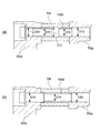
図3はエンジンの第1支持部、第2支持部を含む断面図、図4はエンジンの第3支持部を含む断面図、図5は図4の要部拡大図、図6はエンジンの第4支持部を含む下面側から見た断面図、図7は図6の要部拡大図である。
図3に示すように、第1支持部700Aは、車体フレーム11に設けた左右エンジン支持部707a,707bと、エンジン31に設けた左右エンジン側雌ねじ部703a,703bと、エンジン支持部707a,707bとエンジン側雌ねじ部703a,703bとの間にカラー705a,705bを介在させ、これらのエンジン支持部707a,707b、カラー705a,705b、及びエンジン側雌ねじ部703a,703bをボルト709a,709bで締結している。
3 is a cross-sectional view including a first support portion and a second support portion of the engine, FIG. 4 is a cross-sectional view including a third support portion of the engine, FIG. 5 is an enlarged view of a main part of FIG. 4, and FIG. 4 is a cross-sectional view seen from the lower surface side including the support portion, and FIG. 7 is an enlarged view of a main portion of FIG.
As shown in FIG. 3, the
また、第2支持部700Bは、左右エンジン支持部715a,715bと、エンジン31に設けた左右エンジン側雌ねじ部711a,711bと、エンジン支持部715a,715bとエンジン側雌ねじ部711a,711bとの間にカラー713a,713bを介在させ、これらのエンジン支持部715a,715b、カラー713a,713b、及びエンジン側雌ねじ部711a,711bをボルト717a,717bで締結している。ここで、カラー713bは、割溝入りカラーが用いられている。
Further, the
図4に示すように、第3支持部700Cは、エンジン31の後部に配置される左右エンジン支持部725a,725bに、左右エンジン側貫通穴部721a,721bが締結される。すなわち、図5に示すように、左右エンジン支持部725a,725bと、エンジン31に設けた左右エンジン側貫通穴部721a,721bと、エンジン支持部725a,725bとエンジン側貫通穴部721a,721bとの間にカラー723a,723bを介在させ、これらのエンジン支持部725a,725b、カラー723a,723b、及びエンジン側貫通穴部721a,721bを通しボルト727とナット729で締結している。ここで、カラー723bは、割溝入りカラーが用いられている。
As shown in FIG. 4, in the third support portion 700 </ b> C, left and right engine side through-
第4支持部700Dは、図6に示すように、エンジン31の後部に配置される左右エンジン支持部733a,733bに、左右エンジン側貫通穴部731a,731bが締結される。すなわち、図7に示すように、左右エンジン支持部733a,733bと、エンジン31に設けた左右エンジン側貫通穴部731a,731bと、エンジン支持部733bとエンジン側貫通穴部731bとの間にカラー735bを介在させ、これらのエンジン支持部733a,733b、カラー735b、及びエンジン側貫通穴部731a,731bを通しボルト737とナット739で締結している。
As shown in FIG. 6, in the
ところで、リジッドマウントの自動二輪車では、カラーを介してエンジンと車体フレームとの締結を行う場合、カラーは、締結ボルトとの間に0.3mm程度のクリアランスがある。このため、ボルトに対して径方向に微小に相対変位可能である。カラーとボルトとの相対変位は締結の軸力を受けるフレーム側座面とエンジン側座面との摩擦で抑えられる。リジッドマウントの自動二輪車ではこの座面接触を確実にすることで、エンジン締結部でのエンジンの設定方向外の振動を極力抑えて、乗り心地や操縦性のセッティングを行っていく。 By the way, in a rigid mount motorcycle, when the engine and the body frame are fastened through the collar, the collar has a clearance of about 0.3 mm between the fastening bolt. For this reason, it can be relatively displaced in the radial direction with respect to the bolt. The relative displacement between the collar and the bolt is suppressed by the friction between the frame side seating surface receiving the fastening axial force and the engine side seating surface. Rigid-mount motorcycles ensure the contact of the seat surface to minimize the vibration outside the engine setting direction at the engine fastening part, and set the ride quality and maneuverability.
エンジン31と車体フレーム11との締結部でエンジン31が車体フレーム11に対して設定以外微小に振動すると、自動二輪車1の走行挙動はセッティングしたものから変化していく。このような走行挙動の変化をもたらすエンジン31と車体フレーム11との締結部での想定している方向以外の振動はエンジン31の締結を規定通りに行えば、防ぐことができる。
When the
図8は支持構造のせん断変形状況を(a)〜(c)で表した概念図、図9は支持構造の塑性変形状況を(a)(b)で表した概念図である。なお、以下の概念図では、変形量、歪み量を誇張して描いている。
ここで、排気量の大きなエンジン31を搭載した自動二輪車1で大きなギャップのある道を走行した場合などで、車両が大きな上下の振動を受ける場合、図8(a)に示すカラー両端の座面1a,1bの摩擦による締結が瞬間的に解け、車体フレーム11、カラー1、エンジン31が図8(b)(c)に示すように相対変位し、締結ボルト3がせん断変形を受け、微小に塑性変形する場合がある。
FIG. 8 is a conceptual diagram showing the shear deformation state of the support structure as (a) to (c), and FIG. 9 is a conceptual diagram showing the plastic deformation state of the support structure as (a) and (b). In the following conceptual diagram, the amount of deformation and the amount of distortion are exaggerated.
Here, when the vehicle is subjected to a large vertical vibration when traveling on a road with a large gap in the
図8(b)に示すように、カラー1がエンジン31に固定状態でエンジン31が大きく振動すると、カラー1、エンジン31の接触面でボルト3がせん断変形する。図8(c)に示すように、カラー1がエンジン31に固定状態でエンジン31が大きく振動すると、カラー1、車体フレーム11の接触面でせん断変形が生じ、塑性変形した場合、ボルト3に永久歪5a,5bが残る。
As shown in FIG. 8B, when the
このような永久歪5a,5bがボルト3に残ると、図9(a)(b)に示すように、カラー1とエンジン31や、カラー1と車体フレーム11の座面接触が変化して、座面の一部で接触するようになる場合がある。このように、座面接触が変化すると、振動や操縦性が変化していく場合がある。このような場合は、締結構造を車両に合わせて適切に設定する。従来例には、車体フレーム11とエンジン31との間にカラー1を介する自動二輪車のエンジン支持構造において、カラー1の両端座面に楔状突部を設けた構造が開示されている。かかる構造によれば、カラー1とボルト3との相対変位を極力抑えることが可能であるが、加工にかかるコストが高かった。また、カラー1の周方向での位置決めが必要で作業に手間がかかっていた。
When such
図10は、本発明の実施形態における段付カラー支持構造の支持状況を(a)(b)で表した概念図である。
本発明の自動二輪車1におけるエンジン締結構造では、例えば第1支持部700Aにおいて、図10に示すように、少なくともカラー705aとエンジン支持部707aとの境、又はカラー705aとエンジン側雌ねじ部703aとの境に臨むカラー705aとボルト709aの間に、他の部分よりも大きい隙間741を設けている。これにより、カラー端面743を含む断面でボルト709aに作用するせん断応力の集中が図10(b)に示すように、隙間741の形成範囲に分散されて集中が緩和されるようになっている。すなわち、カラー705aがエンジン側雌ねじ部703aに固定状態で、エンジン31が大きく振動しても、大きなせん断変形が防止される。このため、塑性変形が生じず、座面接触は保たれることとなる。
FIGS. 10A and 10B are conceptual diagrams showing the support status of the stepped collar support structure according to the embodiment of the present invention, as shown in FIGS.
In the engine fastening structure in the
カラー705aは、挿通孔743のエンジン側端部またはフレーム側端部の少なくとも一方の内径D11を大径部とし、カラーの挿通孔743のそれ以外の径を大径部D11よりも径の小さな小径部D12とした。これにより、接触面積の大きい小径部D12の端面で位置決めがなされ、接触面積の小さい大径部D11の端面側でせん断応力の集中が緩和される。
The
カラー大径部D11は幅W11が5mm以上とされ、大径部D11とボルト709aとの直径差(2×d11)はlmm以上とされる。特に重量の大きい大型エンジン31において、大径部D11の幅W(範囲)が5mm以下、直径差が1mm以下で発生するせん断応力の集中が回避可能となる。
Color the large diameter portion D11 has a width W11 is equal to or greater than 5 mm, the diameter difference between the large diameter portion D11 and the
なお、カラー705aの大径部D11側の円筒面には目印部であるケガキ線745が設けられる。これにより、カラー705aの大径部D11側、小径部D12側の判別が容易となる。
本発明における目印部としては、突起、窪み等も含まれる。
Note that a marking
As a mark part in this invention, a protrusion, a hollow, etc. are also included.
図11は段付きカラーの変形例を(a)(b)で表した概念図である。
大径部D11は、図11(a)に示すように、カラー705aAとエンジン支持部707aとの境に臨むカラー705aAの端側に形成されてもよい。また、図11(b)に示すように、大径部D11は、カラー705aAとエンジン支持部707aとの境、及びカラー705aAとエンジン側雌ねじ部703aとの境に臨むカラー705aAの両端側に形成されてもよい。
FIG. 11 is a conceptual diagram showing modified examples of the stepped collars (a) and (b).
As shown in FIG. 11A, the large diameter portion D11 may be formed on the end side of the collar 705aA facing the boundary between the collar 705aA and the
上記の例ではカラー705aに大径部D11を形成することで、隙間741を形成したが、隙間741は、ボルト709の外径を変えることにより設けても良い。
図12は実施形態による段付ボルト支持構造の支持状況を(a)(b)で表した概念図、図13は段付きボルトの変形例を(a)(b)で表した概念図である。
図12に示すように、ボルト709のカラー705のエンジン側端部からエンジン側雌ねじ部703aまで、エンジン支持部709aからカラー705のフレーム側端部まで、又はカラーの中間部のいずれか一つを太径部D13とし、ボルト709のカラー705のエンジン側端部からエンジン側雌ねじ部までを太径部D13とする場合はエンジン支持部709aのフレーム外方端部も太径部D13(図13(b))とし、ボルト709のエンジン支持部からカラー705のフレーム側端部までを太径部D13とする場合はエンジン側雌ねじ部の内側端部も太径部D13とし、ボルト709Aのカラー705の中間部(図13(a))を太径部D13とする場合はエンジン支持部のフレーム外方端部及びエンジン側雌ねじ部703aの内側端部も太径部D13とし、ボルト709のそれ以外の部分を太径部D13よりも径の細い細径部D14とする。
In the above example, the
FIG. 12 is a conceptual diagram showing the support situation of the stepped bolt support structure according to the embodiment in (a) and (b), and FIG. 13 is a conceptual diagram showing modified examples of the stepped bolt in (a) and (b). .
As shown in FIG. 12, any one of the
この構成においても、図12(b)に示すように、カラー705がエンジン31に固定状態で、エンジン31が大きく振動しても、細径部D14によりカラー705とエンジン支持部707aの接触面でカラー705はボルト709に触れない。すなわち、ボルト太径部D13とカラー705で位置決めがなされ、ボルト細径部D14とカラー705との間でせん断応力の集中が緩和される。つまり、カラー705とエンジン支持部707aの接触面での大きなせん断変形を防止できる。これにより、塑性変形も生じず、座面接触は保たれることとなる。
Also in this configuration, as shown in FIG. 12B, even when the
ボルト709の細径部D14は少なくともカラー端部からカラー内の幅W12が5mm以上とされ、ボルト709の細径部D14とカラー挿通孔743の内径直径差(2×d12)はlmm以上とされる。特に大排気量の自動二輪車1のエンジン締結構造において、ボルト細径部D14の幅(範囲)が5mm以下、ボルト細径部D14とカラー705との直径差が1mm以下で発生するせん断応力の集中が回避され、せん断変形を抑える最適なボルト形状となる。
The small diameter portion D14 of the
以上説明したように、本実施形態の自動二輪車によれば、フレーム11、カラー705a、及びエンジン31が相対変位しようとする場合、カラー705aとボルト709aの接触部で位置決めされ、カラー705aとフレーム11、またはカラー705aとエンジン31との間の相対変位が起こる側をコントロールすることができ、ボルト709aのせん断変形を極力抑えることが可能となる。この結果、ボルト709aに塑性変形を起きにくくし、カラー両端での座面接触を安定化させることができる。
As described above, according to the motorcycle of the present embodiment, when the
また、本実施形態の自動二輪車によれば、カラー705aの挿通孔743に段を付けることで、フレーム11、カラー705a、及びエンジン31が相対変位しようとする場合、小径部D12とボルト709aとで位置決めされ、また、大径部D11側端面の面積が小さいので、大径部D11側座面で相対変位が起こる。つまり、カラー705aとフレーム11、またはカラー705aとエンジン31との間の相対変位が起こる側をコントロールすることができる。大径部D11側のボルト709aはカラー705aに触れにくいので、ボルト709aのせん断変形を極力抑えることが可能となる。この結果、ボルト709aに塑性変形を起きにくくし、カラー両端での座面接触を安定化させることができる。
Further, according to the motorcycle of this embodiment, when the
また、本実施形態の自動二輪車によれば、特に大排気量の鞍乗り型車両のエンジン締結構造において、ボルト709aのせん断変形を抑える最適な形状とすることができる。
Further, according to the motorcycle of the present embodiment, it is possible to obtain an optimum shape that suppresses the shear deformation of the
また、本実施形態の自動二輪車によれば、カラー705aの大径部D11側が視認され、締結時の作業が容易になる。
Further, according to the motorcycle of the present embodiment, the large diameter portion D11 side of the
また、本実施形態の自動二輪車によれば、ボルト709に段を付けることで、フレーム11、カラー705、及びエンジン31が相対変位しようとする場合、太径部D13とカラー705とで位置決めされるので、細径部D14側座面で相対変位が起こる。したがって、カラー705とフレーム11、またはカラー705とエンジン31との間の相対変位が起こる側をコントロールでき、かつ、細径部D14側のボルト709はカラー705に触れにくいので、ボルト709のせん断変形を極力抑えることが可能となる。この結果、ボルト709に塑性変形を起きにくくし、カラー両端での座面接触を安定化させることができる。
Further, according to the motorcycle of the present embodiment, when the
また、本実施形態の自動二輪車によれば、特に大排気量の鞍乗り型車両のエンジン締結構造において、ボルト709のせん断変形を抑える最適な形状とすることができる。
Further, according to the motorcycle of the present embodiment, it is possible to obtain an optimum shape that suppresses shear deformation of the
1 自動二輪車(鞍乗り型車両)
11 車体フレーム
31 エンジン
703a エンジン側雌ねじ部
705a カラー
707a エンジン支持部
709a ボルト
741 隙間
743 カラーの挿通孔
745 ケガキ線
D11 大径部
D12 小径部
D13 太径部
D14 細径部
d 直径差
1 Motorcycle (saddle-ride type vehicle)
11
Claims (10)
エンジン(31)に設けたエンジン側雌ねじ部(703a,703b,711a,711b)と、
前記エンジン支持部(707a,707b,715a,715b)と前記エンジン側雌ねじ部(703a,703b,711a,711b)との間にカラー(705a,705b,713a,713b,705aA,705aB)を介在させ、
これらのエンジン支持部(707a,707b,715a,715b)、カラー(705a,705b,713a,713b,705aA,705aB)、及びエンジン側雌ねじ部(703a,703b,711a,711b)をボルト(709a,709b,717a,717b)で締結する鞍乗り型車両(1)であって、
少なくとも前記カラー(705a,705b,713a,713b,705aA,705aB)と前記エンジン支持部(707a,707b,715a,715b)との境及び前記カラー(705a,705b,713a,713b,705aA,705aB)と前記エンジン側雌ねじ部(703a,703b,711a,711b)との境の一方に臨む前記カラー(705a,705b,713a,713b,705aA,705aB)と前記ボルト(709a,709b,717a,717b)の間に、上記境以外の部分の前記カラー(705a,705b,713a,713b,705aA,705aB)と前記ボルト(709a,709b,717a,717b)の間よりも大きい径方向の隙間(741)を有し、
前記隙間(741)を設けるために、
前記カラー(705a,705b,713a,713b,705aA,705aB)の挿通孔(743)のエンジン側端部またはフレーム側端部の少なくとも一方の内径を大径部(D11)とし、
前記カラー(705a,705b,713a,713b,705aA,705aB)の挿通孔(743)のそれ以外の径を該大径部(D11)よりも径の小さな小径部(D12)としたことを特徴とする鞍乗り型車両(1)。 An engine support (707a, 707b, 715a, 715b) provided on the vehicle body frame (11) ;
Engine-side female screw parts (703a, 703b, 711a, 711b) provided in the engine (31) ;
A collar (705a, 705b, 713a, 713b, 705aA, 705aB) is interposed between the engine support portion (707a, 707b, 715a, 715b) and the engine side female screw portion (703a, 703b, 711a , 711b) ,
These engine support portions (707a, 707b, 715a, 715b) , collars (705a, 705b, 713a, 713b, 705aA, 705aB) , and engine side female thread portions (703a, 703b, 711a , 711b ) are bolted (709a, 709b). , 717a, 717b) , a saddle-ride type vehicle (1) ,
At least the collar (705a, 705b, 713a, 713b , 705aA, 705aB) and said engine supporting portion (707a, 707b, 715a, 715b ) boundary and the color of the (705a, 705b, 713a, 713b , 705aA, 705aB) and Between the collar (705a, 705b, 713a, 713b, 705aA, 705aB) and the bolt (709a, 709b, 717a, 717b) facing one of the boundaries with the engine-side female thread (703a, 703b, 711a , 711b) In addition , a gap (741) in the radial direction larger than the space between the collar (705a, 705b, 713a, 713b, 705aA, 705aB) and the bolt (709a, 709b, 717a, 717b) other than the border is provided. ,
In order to provide the gap (741),
The inner diameter of at least one of the engine side end or the frame side end of the insertion hole (743) of the collar (705a, 705b, 713a, 713b, 705aA, 705aB) is defined as a large diameter portion (D11),
The other diameter of the insertion hole (743) of the collar (705a, 705b, 713a, 713b, 705aA, 705aB) is a small diameter part (D12) smaller in diameter than the large diameter part (D11). A saddle riding type vehicle (1) .
前記カラー大径部(D11)は幅(W11)5mm以上とされ、
前記大径部(D11)と前記ボルト(709a,709b,717a,717b)との直径差(2×d11)はlmm以上とされることを特徴とする鞍乗り型車両(1)。 A saddle-ride type vehicle (1) according to claim 1 ,
The color large-diameter portion (D11) is the width (W11) 5 mm or more,
It said large diameter portion (D11) and said bolt (709a, 709b, 717a, 717b ) diameter difference between the (2 × d11) is saddle-ride type vehicle (1), characterized in that are least lmm.
前記カラー(705a,705b,713a,713b,705aA,705aB)の大径部(D11)側の円筒面に目印部(745)が設けられることを特徴とする鞍乗り型車両(1)。 A saddle-ride type vehicle (1) according to claim 2 ,
A saddle-ride type vehicle (1) , wherein a mark portion (745) is provided on a cylindrical surface of the collar (705a, 705b, 713a, 713b, 705aA, 705aB) on the large diameter portion (D11) side.
エンジン(31)に設けたエンジン側雌ねじ部(703a)と、
前記エンジン支持部(707a)と前記エンジン側雌ねじ部(703a)との間にカラー(705)を介在させ、
これらのエンジン支持部(707a)、カラー(705)、及びエンジン側雌ねじ部(703a)をボルト(709,709A,709B)で締結する鞍乗り型車両(1)であって、
少なくとも前記カラー(705)と前記エンジン支持部(707a)との境及び前記カラー(705)と前記エンジン側雌ねじ部(703a)との境の一方に臨む前記カラー(705)と前記ボルト(709,709A,709B)の間に、上記境以外の部分の前記カラー(705)と前記ボルト(709,709A,709B)の間よりも大きい径方向の隙間(741)を有し、
前記隙間(741)を設けるために、前記ボルト(709,709A,709B)に太径部(D13)と、該太径部(D13)よりも径の細い細径部(D14)とを形成し、
前記ボルト(709,709A,709B)のカラー(705)のエンジン側端部からエンジン側雌ねじ部(703a)まで、エンジン支持部(707a)からカラー(705)のフレーム側端部まで、又はカラー(705)の中間部のいずれか一つを前記太径部(D13)とし、
前記ボルト(709)のカラー(705)のエンジン側端部からエンジン側雌ねじ部(703a)までを前記太径部(D13)とする場合は、前記ボルト(709)のエンジン支持部(707a)のフレーム外方端部も太径部(D13)とし、
前記ボルト(709B)のエンジン支持部(707a)からカラー(705)のフレーム側端部までを前記太径部(D13)とする場合は、前記ボルト(709B)のエンジン側雌ねじ部(703a)の内側端部も太径部(D13)とし、
前記ボルト(709A)のカラー(705)の中間部を前記太径部(D13)とする場合は、前記ボルト(709A)のエンジン支持部(707a)のフレーム外方端部及びエンジン側雌ねじ部(703a)の内側端部も太径部(D13)とし、
前記ボルト(709,709A,709B)のそれ以外の部分を前記細径部(D14)としたことを特徴とする鞍乗り型車両(1)。 An engine support (707a) provided on the vehicle body frame (11);
An engine-side female thread portion (703a) provided in the engine (31);
A collar (705) is interposed between the engine support part (707a) and the engine side female thread part (703a),
A saddle-ride type vehicle (1) for fastening these engine support part (707a), collar (705), and engine side female thread part (703a) with bolts (709, 709A, 709B),
The collar (705) and the bolt (709,) facing at least one of the boundary between the collar (705) and the engine support portion (707a) and the boundary between the collar (705) and the engine-side female screw portion (703a). 709A, 709B) having a larger radial gap (741) than between the collar (705) and the bolts (709, 709A, 709B) other than the border,
In order to provide the gap (741), the bolt (709, 709A, 709B) is formed with a large diameter portion (D13) and a narrow diameter portion (D14) having a diameter smaller than that of the large diameter portion (D13). ,
From the engine side end of the collar (705) of the bolt (709, 709A, 709B) to the engine side female thread (703a), from the engine support (707a) to the frame side end of the collar (705) , or the collar ( any one of the intermediate portion 705) and the large diameter portion (D13),
If the engine side female threaded portion from the engine side end portion (703a) to the large diameter portion of the collar (705) of the bolt (709) (D13), the engine support portion of the bolt (709) in (707a) frame outer end portion is also large-diameter portion and (D13),
If the engine supporting portion and the large diameter portion to the frame side end portion of the collar from (707a) (705) (D13 ) of said bolt (709B) is the engine side female threaded portion of the bolt (709B) of (703a) inner end also large-diameter portion and (D13),
If the said large diameter portion and an intermediate portion (D13), a frame outer end portion and the engine side female threaded portion of the engine supporting portion of the bolt (709A) (707a) of the collar (705) of the bolt (709A) ( inner end of 703a) was also large-diameter portion and (D13),
A saddle-ride type vehicle (1) , wherein the other portion of the bolt (709, 709A, 709B) is the small diameter portion (D14 ) .
前記ボルト(709,709A,709B)の細径部(D14)は少なくともカラー端部からカラー(705)内に幅(W12)5mm以上とされ、
前記ボルト(709,709A,709B)の細径部(D14)と前記カラー(705)の挿通孔(743)の内径直径差(2×d12)はlmm以上とされることを特徴とする鞍乗り型車両(1)。 A saddle riding type vehicle (1) according to claim 4,
The bolt (709,709A, 709B) small-diameter portion of the (D14) is at least from the collar end portion within the collar (705) width (W12) 5 mm or more,
The bolt (709,709A, 709B) inner diameter difference between the diameters of the insertion hole (743) of said small-diameter portion of the (D14) Color (705) (2 × d12) is saddle-ride, characterized in that are least lmm Type vehicle (1) .
エンジン(31)に設けた貫通孔(721a,721b,731a,731b)と、
前記エンジン支持部(725a,725b,733b)と前記エンジン(31)の貫通孔(721a,721b,731b)との間にカラー(723a,723b,735b)を介在させ、
これらの左右一対のエンジン支持部(725a,725b,733a,733b)、カラー(723a,723b,735b)、及びエンジン(31)の貫通孔(721a,721b,731a,731b)を、端部に雄ねじが切られた貫通ボルト(727,737)と、当該貫通ボルト(727,737)の雄ねじ側端部と螺合するナット(729,739)で締結する鞍乗り型車両(1)であって、
少なくとも前記カラー(723a,723b,735b)と前記エンジン支持部(725a,725b,733b)との境及び前記カラー(723a,723b,735b)と前記貫通孔(721a,721b,731b)との境の一方に臨む前記カラー(723a,723b,735b)と前記ボルト(727,737)の間に、上記境以外の部分の前記カラー(723a,723b,735b)と前記ボルト(727,737)の間よりも大きい径方向の隙間(741)を有し、
前記隙間(741)を設けるために、
前記カラー(723a,723b,735b)の挿通孔(743)のエンジン側端部またはフレーム側端部の少なくとも一方の内径を大径部(D11)とし、
前記カラー(723a,723b,735b)の挿通孔(743)のそれ以外の径を該大径部(D11)よりも径の小さな小径部(D12)としたことを特徴とする鞍乗り型車両(1)。 A pair of left and right engine support portions (725a, 725b, 733a, 733b) provided on the vehicle body frame (11) ;
Through holes (721a, 721b, 731a, 731b) provided in the engine (31) ;
Collars (723a, 723b, 735b) are interposed between the engine support portions (725a, 725b, 733b) and the through holes (721a, 721b, 731b) of the engine (31) ,
A pair of left and right engine support portions (725a, 725b, 733a, 733b) , a collar (723a, 723b, 735b) , and a through hole (721a, 721b, 731a, 731b) of the engine (31) are provided with male screws at the ends. A saddle-ride type vehicle (1) that is fastened with a through bolt (727, 737) that has been cut off and a nut (729, 739) that is screwed into a male screw side end of the through bolt (727, 737) ,
At least the collar (723a, 723b, 735b) and said engine supporting portion (725a, 725b, 733b) boundary and the color of the (723a, 723b, 735b) and the through-hole (721a, 721b, 731b) boundary between the Meanwhile the collar facing the (723a, 723b, 735b) between the bolt (727,737), said collar portion other than the boundary (723a, 723b, 735b) and from between said bolt (727,737) Has a large radial gap (741) ,
In order to provide the gap (741),
The inner diameter of at least one of the engine side end or the frame side end of the insertion hole (743) of the collar (723a, 723b, 735b) is a large diameter part (D11),
Said collar (723a, 723b, 735b) saddle type vehicle the other diameter of the insertion hole (743), characterized in that the small diameter portion of diameter than the large diameter portion (D11) and (D12) of ( 1)
前記カラー大径部(D11)は幅(W11)5mm以上とされ、
前記大径部(D11)と前記ボルト(727,737)との直径差(2×d11)はlmm以上とされることを特徴とする鞍乗り型車両(1)。 A saddle riding type vehicle (1) according to claim 6 ,
The color large-diameter portion (D11) is the width (W11) 5 mm or more,
The diameter difference between the large diameter portion (D11) and the bolt (727,737) (2 × d11) is saddle-ride type vehicle (1), characterized in that are least lmm.
前記カラー(723a,723b,735b)の大径部(D11)側の円筒面に目印部(745)が設けられることを特徴とする鞍乗り型車両(1)。 A saddle riding type vehicle (1) according to claim 7 ,
A saddle-ride type vehicle (1) , wherein a mark portion (745) is provided on a cylindrical surface of the collar (723a, 723b, 735b) on the large diameter portion (D11) side.
エンジン(31)に設けた貫通孔(721a,721b,731a,731b)と、
前記エンジン支持部(725a,725b,733b)と前記エンジン(31)の貫通孔(721a,721b,731b)との間にカラー(723a,723b,735b)を介在させ、
これらの左右一対のエンジン支持部(725a,725b,733a,733b)、カラー(723a,723b,735b)、及びエンジン(31)の貫通孔(721a,721b,731a,731b)を、端部に雄ねじが切られた貫通ボルト(727,737)と、当該貫通ボルト(727,737)の雄ねじ側端部と螺合するナット(729,739)で締結する鞍乗り型車両(1)であって、
少なくとも前記カラー(723a,723b,735b)と前記エンジン支持部(725a,725b,733b)との境及び前記カラー(723a,723b,735b)と前記貫通孔(721a,721b,731b)との境の一方に臨む前記カラー(723a,723b,735b)と前記ボルト(727,737)の間に、上記境以外の部分の前記カラー(723a,723b,735b)と前記ボルト(727,737)の間よりも大きい径方向の隙間(741)を有し、
前記隙間(741)を設けるために、前記ボルト(727,737)に太径部(D13)と、該太径部(D13)よりも径の細い細径部(D14)とを形成し、
前記ボルト(727,737)のカラー(723a,723b,735b)のエンジン側端部から貫通孔(721a,721b,731b)まで、エンジン支持部(725a,725b,733b)からカラー(723a,723b,735b)のフレーム側端部まで、又はカラー(723a,723b,735b)の中間部のいずれか一つを前記太径部(D13)とし、
前記ボルト(727,737)のカラー(723a,723b,735b)のエンジン側端部から貫通孔(721a,721b,731b)までを前記太径部(D13)とする場合は、前記ボルト(727,737)のエンジン支持部(725a,725b,733b)のフレーム外方端部も太径部(D13)とし、
前記ボルト(727,737)のエンジン支持部(725a,725b,733b)からカラー(723a,723b,735b)のフレーム側端部までを前記太径部(D13)とする場合は、前記ボルト(727,737)の貫通孔(721a,721b,731b)の内側端部も太径部(D13)とし、
前記ボルト(727,737)のカラー(723a,723b,735b)の中間部を前記太径部(D13)とする場合は、前記ボルト(727,737)のエンジン支持部(725a,725b,733b)のフレーム外方端部及び貫通孔(721a,721b,731b)の内側端部も太径部(D13)とし、
前記ボルト(727,737)のそれ以外の部分を前記細径部(D14)としたことを特徴とする鞍乗り型車両(1)。 A pair of left and right engine support portions (725a, 725b, 733a, 733b) provided on the vehicle body frame (11);
Through holes (721a, 721b, 731a, 731b) provided in the engine (31);
Collars (723a, 723b, 735b) are interposed between the engine support portions (725a, 725b, 733b) and the through holes (721a, 721b, 731b) of the engine (31),
A pair of left and right engine support portions (725a, 725b, 733a, 733b), a collar (723a, 723b, 735b), and a through hole (721a, 721b, 731a, 731b) of the engine (31) are provided with male screws at the ends. A saddle-ride type vehicle (1) that is fastened with a through bolt (727, 737) that has been cut off and a nut (729, 739) that is screwed into a male screw side end of the through bolt (727, 737),
At least the boundary between the collar (723a, 723b, 735b) and the engine support (725a, 725b, 733b) and the boundary between the collar (723a, 723b, 735b) and the through hole (721a, 721b, 731b). Between the collar (723a, 723b, 735b) facing the one side and the bolt (727, 737), between the collar (723a, 723b, 735b) and the bolt (727, 737) of the portion other than the boundary. Has a large radial gap (741),
In order to provide the gap (741), the bolt (727, 737) is formed with a large diameter portion (D13) and a small diameter portion (D14) having a diameter smaller than the large diameter portion (D13),
From the engine side end of the collar (723a, 723b, 735b) of the bolt (727, 737) to the through hole (721a, 721b, 731b), from the engine support (725a, 725b, 733b) to the collar (723a, 723b, to the frame side end portion of the 735b), or a color (and 723a, 723b, and the large diameter portion of one of the middle portion of the 735b) (D13),
Color of the bolt (727,737) (723a, 723b, 735b) through holes from the engine side end portion of the (721a, 721b, 731b) if the said large diameter portion to (D13), said bolt (727, engine supporting portion 737) (725a, 725b, 733b frame outer end portion is also large-diameter portion) and (D13),
The engine supporting portion of the bolt (727,737) (725a, 725b, 733b) color from (723a, 723b, 735b) if the said large diameter portion to the frame side end portion of the (D13), said bolt (727 , through holes (721a to 737), and 721b, the inner end portion of the 731b) also large-diameter portion and (D13),
Color of the bolt (727,737) (723a, 723b, 735b) if said large diameter portion of the intermediate portion and the (D13) of said engine supporting portion of the bolt (727,737) (725a, 725b, 733b) inner end of the frame outer end portion and the through hole (721a, 721b, 731b) and also large-diameter portion and (D13),
A saddle-ride type vehicle (1) , wherein the other portion of the bolt (727, 737) is the small-diameter portion (D14 ) .
前記ボルト(727,737)の細径部(D14)は少なくともカラー端部からカラー(723a,723b,735b)内に幅(W12)5mm以上とされ、
前記ボルト(727,737)の細径部(D14)と前記カラー(723a,723b,735b)の挿通孔(743)の内径直径差(2×d12)はlmm以上とされることを特徴とする鞍乗り型車両(1)。 A saddle riding type vehicle (1) according to claim 9 ,
The small diameter portion of the bolt (727,737) (D14) is at least a color from the color ends (723a, 723b, 735b) and the width (W12) 5 mm or more within,
Small diameter portion (D14) and the collar of the bolt (727,737) (723a, 723b, 735b) inner diameter difference between the diameters of the insertion hole (743) of the (2 × d12) is characterized in that it is a more lmm A saddle-ride type vehicle (1) .
Priority Applications (3)
| Application Number | Priority Date | Filing Date | Title |
|---|---|---|---|
| JP2009087781A JP5414331B2 (en) | 2009-03-31 | 2009-03-31 | Saddle riding |
| EP10154247A EP2236404B1 (en) | 2009-03-31 | 2010-02-22 | Saddle type vehicle |
| US12/718,686 US8381863B2 (en) | 2009-03-31 | 2010-03-05 | Connection structure arrangement between a frame member and an engine of a saddle-type vehicle, and vehicle incorporating same |
Applications Claiming Priority (1)
| Application Number | Priority Date | Filing Date | Title |
|---|---|---|---|
| JP2009087781A JP5414331B2 (en) | 2009-03-31 | 2009-03-31 | Saddle riding |
Publications (2)
| Publication Number | Publication Date |
|---|---|
| JP2010235058A JP2010235058A (en) | 2010-10-21 |
| JP5414331B2 true JP5414331B2 (en) | 2014-02-12 |
Family
ID=41786475
Family Applications (1)
| Application Number | Title | Priority Date | Filing Date |
|---|---|---|---|
| JP2009087781A Active JP5414331B2 (en) | 2009-03-31 | 2009-03-31 | Saddle riding |
Country Status (3)
| Country | Link |
|---|---|
| US (1) | US8381863B2 (en) |
| EP (1) | EP2236404B1 (en) |
| JP (1) | JP5414331B2 (en) |
Families Citing this family (7)
| Publication number | Priority date | Publication date | Assignee | Title |
|---|---|---|---|---|
| ES2593860T3 (en) * | 2008-09-30 | 2016-12-13 | Honda Motor Co., Ltd. | Engine suspension structure for two-wheeled motor vehicle |
| JP6029407B2 (en) * | 2012-09-28 | 2016-11-24 | 川崎重工業株式会社 | Saddle riding vehicle |
| JP6244240B2 (en) * | 2014-03-26 | 2017-12-06 | 本田技研工業株式会社 | Saddle riding vehicle |
| US10036465B2 (en) * | 2015-07-17 | 2018-07-31 | Shimano Inc. | Bicycle component |
| US10940910B2 (en) | 2017-08-04 | 2021-03-09 | Shimano Inc. | Bicycle component and mounting structure for bicycle component |
| JP6921718B2 (en) * | 2017-08-04 | 2021-08-18 | 株式会社シマノ | Bicycle components and mounting structure of bicycle components |
| JP7191911B2 (en) * | 2020-09-25 | 2022-12-19 | 本田技研工業株式会社 | vehicle |
Family Cites Families (20)
| Publication number | Priority date | Publication date | Assignee | Title |
|---|---|---|---|---|
| AU539919B2 (en) * | 1980-09-22 | 1984-10-25 | Honda Giken Kogyo Kabushiki Kaisha | Motorcycle frame |
| JPS6230005U (en) * | 1985-08-08 | 1987-02-23 | ||
| JPS62105896U (en) * | 1985-12-25 | 1987-07-06 | ||
| JPH0162996U (en) * | 1987-10-16 | 1989-04-21 | ||
| JPH0168999U (en) * | 1987-10-26 | 1989-05-08 | ||
| JPH01195196A (en) * | 1988-01-29 | 1989-08-07 | Suzuki Motor Co Ltd | Engine suspension of saddle type vehicle |
| JPH01249586A (en) * | 1988-03-31 | 1989-10-04 | Suzuki Motor Co Ltd | Engine mounting device for vehicle |
| JP2726451B2 (en) * | 1988-10-20 | 1998-03-11 | ヤマハ発動機株式会社 | Motorcycle engine suspension structure |
| JPH0331081A (en) * | 1989-06-28 | 1991-02-08 | Yamaha Motor Co Ltd | Engine suspension device of vehicle |
| JPH04365688A (en) * | 1991-06-13 | 1992-12-17 | Yamaha Motor Co Ltd | Engine support structure for motorcycle |
| JPH10236376A (en) * | 1997-02-27 | 1998-09-08 | Honda Motor Co Ltd | Engine suspension device for motorcycle |
| US6315072B1 (en) * | 1999-07-29 | 2001-11-13 | Harley-Davidson Motor Company Group, Inc. | Motorcycle engine mounting assembly |
| JP4105442B2 (en) * | 2002-01-31 | 2008-06-25 | 本田技研工業株式会社 | Engine mount structure for motorcycles |
| CA2474470C (en) * | 2002-02-20 | 2008-09-16 | Yamaha Hatsudoki Kabushiki Kaisha | Engine valve train device |
| JP4217091B2 (en) * | 2003-03-25 | 2009-01-28 | 本田技研工業株式会社 | Water pump for engine cooling |
| JP4236176B2 (en) * | 2003-05-30 | 2009-03-11 | 本田技研工業株式会社 | Engine support structure for motorcycles |
| US7469689B1 (en) * | 2004-09-09 | 2008-12-30 | Jones Daniel W | Fluid cooled supercharger |
| JP4627226B2 (en) * | 2005-07-12 | 2011-02-09 | 本田技研工業株式会社 | Body structure of motorcycle |
| US7690467B2 (en) * | 2007-07-02 | 2010-04-06 | Buell Motorcycle Company | Motorcycle frame with fuel-storage and break-away engine mounts |
| JP5162302B2 (en) * | 2008-03-31 | 2013-03-13 | 本田技研工業株式会社 | Motorcycle body frame |
-
2009
- 2009-03-31 JP JP2009087781A patent/JP5414331B2/en active Active
-
2010
- 2010-02-22 EP EP10154247A patent/EP2236404B1/en active Active
- 2010-03-05 US US12/718,686 patent/US8381863B2/en not_active Expired - Fee Related
Also Published As
| Publication number | Publication date |
|---|---|
| EP2236404B1 (en) | 2012-07-11 |
| JP2010235058A (en) | 2010-10-21 |
| EP2236404A1 (en) | 2010-10-06 |
| US8381863B2 (en) | 2013-02-26 |
| US20100243364A1 (en) | 2010-09-30 |
Similar Documents
| Publication | Publication Date | Title |
|---|---|---|
| JP5414331B2 (en) | Saddle riding | |
| JP5261827B2 (en) | Canister mounting structure for saddle-ride type vehicles | |
| JP5239087B2 (en) | Saddle riding | |
| JP6459859B2 (en) | Sensor support structure and motorcycle | |
| US7503415B2 (en) | Engine support structure of motorcycle | |
| EP2236399B1 (en) | Straddle-ride type vehicle | |
| JP5323533B2 (en) | Saddle riding | |
| EP2048051B1 (en) | Straddle-type vehicle | |
| US10494047B2 (en) | Saddle-riding-type vehicle cable support structure | |
| JP2019116263A (en) | Saddle-riding type vehicle | |
| US9150276B2 (en) | Saddle-ride type vehicle | |
| US10780936B2 (en) | Straddle-type vehicle | |
| US20050247505A1 (en) | Frame and bracket system for motorized vehicle | |
| JP2010058762A (en) | Saddle-riding type vehicle | |
| JP5414330B2 (en) | Saddle riding | |
| JP3157690U (en) | Saddle riding vehicle | |
| JP2006021625A (en) | Motorcycle | |
| JP3157691U (en) | Saddle riding vehicle | |
| JP2006240460A (en) | Resin-made member engaging structure of motorcycle | |
| JP6268554B2 (en) | Holding structure for saddle-ride type vehicle | |
| JP2019064298A (en) | Saddle-riding type vehicle headlight supporting structure | |
| JP2023019172A (en) | Meter bracket for saddle type vehicle | |
| JP2019064297A (en) | Saddle-riding type vehicle frame structure | |
| JP2019031285A (en) | Sensor support structure and motorcycle | |
| JP2019011063A (en) | Sensor support structure and motorcycle |
Legal Events
| Date | Code | Title | Description |
|---|---|---|---|
| A621 | Written request for application examination |
Free format text: JAPANESE INTERMEDIATE CODE: A621 Effective date: 20111124 |
|
| A521 | Request for written amendment filed |
Free format text: JAPANESE INTERMEDIATE CODE: A523 Effective date: 20120518 |
|
| A977 | Report on retrieval |
Free format text: JAPANESE INTERMEDIATE CODE: A971007 Effective date: 20130306 |
|
| A131 | Notification of reasons for refusal |
Free format text: JAPANESE INTERMEDIATE CODE: A131 Effective date: 20130319 |
|
| A521 | Request for written amendment filed |
Free format text: JAPANESE INTERMEDIATE CODE: A523 Effective date: 20130517 |
|
| RD02 | Notification of acceptance of power of attorney |
Free format text: JAPANESE INTERMEDIATE CODE: A7422 Effective date: 20130517 |
|
| RD04 | Notification of resignation of power of attorney |
Free format text: JAPANESE INTERMEDIATE CODE: A7424 Effective date: 20130520 |
|
| TRDD | Decision of grant or rejection written | ||
| A01 | Written decision to grant a patent or to grant a registration (utility model) |
Free format text: JAPANESE INTERMEDIATE CODE: A01 Effective date: 20131015 |
|
| A61 | First payment of annual fees (during grant procedure) |
Free format text: JAPANESE INTERMEDIATE CODE: A61 Effective date: 20131112 |
|
| R150 | Certificate of patent or registration of utility model |
Ref document number: 5414331 Country of ref document: JP Free format text: JAPANESE INTERMEDIATE CODE: R150 |
|
| R250 | Receipt of annual fees |
Free format text: JAPANESE INTERMEDIATE CODE: R250 |