JP5410995B2 - Sliding and rotating hinge module - Google Patents
Sliding and rotating hinge module Download PDFInfo
- Publication number
- JP5410995B2 JP5410995B2 JP2009550626A JP2009550626A JP5410995B2 JP 5410995 B2 JP5410995 B2 JP 5410995B2 JP 2009550626 A JP2009550626 A JP 2009550626A JP 2009550626 A JP2009550626 A JP 2009550626A JP 5410995 B2 JP5410995 B2 JP 5410995B2
- Authority
- JP
- Japan
- Prior art keywords
- slider
- drum
- bracket
- hinge module
- stator
- Prior art date
- Legal status (The legal status is an assumption and is not a legal conclusion. Google has not performed a legal analysis and makes no representation as to the accuracy of the status listed.)
- Expired - Fee Related
Links
- 239000000872 buffer Substances 0.000 claims description 16
- 239000004519 grease Substances 0.000 claims description 10
- 230000003139 buffering effect Effects 0.000 claims description 9
- 230000007246 mechanism Effects 0.000 claims description 8
- 230000035939 shock Effects 0.000 claims description 3
- 239000002184 metal Substances 0.000 description 5
- 229910052751 metal Inorganic materials 0.000 description 5
- -1 but not limited to Substances 0.000 description 3
- 230000008859 change Effects 0.000 description 3
- 239000000463 material Substances 0.000 description 3
- PXHVJJICTQNCMI-UHFFFAOYSA-N Nickel Chemical compound [Ni] PXHVJJICTQNCMI-UHFFFAOYSA-N 0.000 description 2
- 229910000831 Steel Inorganic materials 0.000 description 2
- 230000008901 benefit Effects 0.000 description 2
- 239000012530 fluid Substances 0.000 description 2
- 229920000642 polymer Polymers 0.000 description 2
- 238000005381 potential energy Methods 0.000 description 2
- 239000010959 steel Substances 0.000 description 2
- 229920004943 Delrin® Polymers 0.000 description 1
- 230000004308 accommodation Effects 0.000 description 1
- 230000009471 action Effects 0.000 description 1
- 239000002390 adhesive tape Substances 0.000 description 1
- 238000013016 damping Methods 0.000 description 1
- 230000003247 decreasing effect Effects 0.000 description 1
- 230000002950 deficient Effects 0.000 description 1
- 239000011521 glass Substances 0.000 description 1
- 238000004519 manufacturing process Methods 0.000 description 1
- 239000007769 metal material Substances 0.000 description 1
- 238000012986 modification Methods 0.000 description 1
- 230000004048 modification Effects 0.000 description 1
- 238000000465 moulding Methods 0.000 description 1
- 229910052759 nickel Inorganic materials 0.000 description 1
- 239000002861 polymer material Substances 0.000 description 1
- 238000007789 sealing Methods 0.000 description 1
- 238000000926 separation method Methods 0.000 description 1
- 229910001220 stainless steel Inorganic materials 0.000 description 1
- 239000010935 stainless steel Substances 0.000 description 1
- 230000001629 suppression Effects 0.000 description 1
Images


Classifications
-
- B—PERFORMING OPERATIONS; TRANSPORTING
- B60—VEHICLES IN GENERAL
- B60R—VEHICLES, VEHICLE FITTINGS, OR VEHICLE PARTS, NOT OTHERWISE PROVIDED FOR
- B60R11/00—Arrangements for holding or mounting articles, not otherwise provided for
- B60R11/02—Arrangements for holding or mounting articles, not otherwise provided for for radio sets, television sets, telephones, or the like; Arrangement of controls thereof
- B60R11/0229—Arrangements for holding or mounting articles, not otherwise provided for for radio sets, television sets, telephones, or the like; Arrangement of controls thereof for displays, e.g. cathodic tubes
- B60R11/0235—Arrangements for holding or mounting articles, not otherwise provided for for radio sets, television sets, telephones, or the like; Arrangement of controls thereof for displays, e.g. cathodic tubes of flat type, e.g. LCD
-
- B—PERFORMING OPERATIONS; TRANSPORTING
- B60—VEHICLES IN GENERAL
- B60R—VEHICLES, VEHICLE FITTINGS, OR VEHICLE PARTS, NOT OTHERWISE PROVIDED FOR
- B60R11/00—Arrangements for holding or mounting articles, not otherwise provided for
- B60R2011/0001—Arrangements for holding or mounting articles, not otherwise provided for characterised by position
- B60R2011/0003—Arrangements for holding or mounting articles, not otherwise provided for characterised by position inside the vehicle
-
- B—PERFORMING OPERATIONS; TRANSPORTING
- B60—VEHICLES IN GENERAL
- B60R—VEHICLES, VEHICLE FITTINGS, OR VEHICLE PARTS, NOT OTHERWISE PROVIDED FOR
- B60R11/00—Arrangements for holding or mounting articles, not otherwise provided for
- B60R2011/0042—Arrangements for holding or mounting articles, not otherwise provided for characterised by mounting means
- B60R2011/008—Adjustable or movable supports
- B60R2011/0082—Adjustable or movable supports collapsible, e.g. for storing after use
-
- B—PERFORMING OPERATIONS; TRANSPORTING
- B60—VEHICLES IN GENERAL
- B60R—VEHICLES, VEHICLE FITTINGS, OR VEHICLE PARTS, NOT OTHERWISE PROVIDED FOR
- B60R11/00—Arrangements for holding or mounting articles, not otherwise provided for
- B60R2011/0042—Arrangements for holding or mounting articles, not otherwise provided for characterised by mounting means
- B60R2011/008—Adjustable or movable supports
- B60R2011/0084—Adjustable or movable supports with adjustment by linear movement in their operational position
-
- B—PERFORMING OPERATIONS; TRANSPORTING
- B60—VEHICLES IN GENERAL
- B60R—VEHICLES, VEHICLE FITTINGS, OR VEHICLE PARTS, NOT OTHERWISE PROVIDED FOR
- B60R11/00—Arrangements for holding or mounting articles, not otherwise provided for
- B60R2011/0042—Arrangements for holding or mounting articles, not otherwise provided for characterised by mounting means
- B60R2011/008—Adjustable or movable supports
- B60R2011/0085—Adjustable or movable supports with adjustment by rotation in their operational position
-
- B—PERFORMING OPERATIONS; TRANSPORTING
- B60—VEHICLES IN GENERAL
- B60R—VEHICLES, VEHICLE FITTINGS, OR VEHICLE PARTS, NOT OTHERWISE PROVIDED FOR
- B60R11/00—Arrangements for holding or mounting articles, not otherwise provided for
- B60R2011/0042—Arrangements for holding or mounting articles, not otherwise provided for characterised by mounting means
- B60R2011/008—Adjustable or movable supports
- B60R2011/0092—Adjustable or movable supports with motorization
-
- E—FIXED CONSTRUCTIONS
- E05—LOCKS; KEYS; WINDOW OR DOOR FITTINGS; SAFES
- E05D—HINGES OR SUSPENSION DEVICES FOR DOORS, WINDOWS OR WINGS
- E05D15/00—Suspension arrangements for wings
- E05D15/06—Suspension arrangements for wings for wings sliding horizontally more or less in their own plane
- E05D15/0604—Suspension arrangements for wings for wings sliding horizontally more or less in their own plane allowing an additional movement
-
- E—FIXED CONSTRUCTIONS
- E05—LOCKS; KEYS; WINDOW OR DOOR FITTINGS; SAFES
- E05F—DEVICES FOR MOVING WINGS INTO OPEN OR CLOSED POSITION; CHECKS FOR WINGS; WING FITTINGS NOT OTHERWISE PROVIDED FOR, CONCERNED WITH THE FUNCTIONING OF THE WING
- E05F1/00—Closers or openers for wings, not otherwise provided for in this subclass
- E05F1/08—Closers or openers for wings, not otherwise provided for in this subclass spring-actuated, e.g. for horizontally sliding wings
- E05F1/16—Closers or openers for wings, not otherwise provided for in this subclass spring-actuated, e.g. for horizontally sliding wings for sliding wings
-
- E—FIXED CONSTRUCTIONS
- E05—LOCKS; KEYS; WINDOW OR DOOR FITTINGS; SAFES
- E05Y—INDEXING SCHEME ASSOCIATED WITH SUBCLASSES E05D AND E05F, RELATING TO CONSTRUCTION ELEMENTS, ELECTRIC CONTROL, POWER SUPPLY, POWER SIGNAL OR TRANSMISSION, USER INTERFACES, MOUNTING OR COUPLING, DETAILS, ACCESSORIES, AUXILIARY OPERATIONS NOT OTHERWISE PROVIDED FOR, APPLICATION THEREOF
- E05Y2201/00—Constructional elements; Accessories therefor
- E05Y2201/20—Brakes; Disengaging means; Holders; Stops; Valves; Accessories therefor
- E05Y2201/21—Brakes
-
- E—FIXED CONSTRUCTIONS
- E05—LOCKS; KEYS; WINDOW OR DOOR FITTINGS; SAFES
- E05Y—INDEXING SCHEME ASSOCIATED WITH SUBCLASSES E05D AND E05F, RELATING TO CONSTRUCTION ELEMENTS, ELECTRIC CONTROL, POWER SUPPLY, POWER SIGNAL OR TRANSMISSION, USER INTERFACES, MOUNTING OR COUPLING, DETAILS, ACCESSORIES, AUXILIARY OPERATIONS NOT OTHERWISE PROVIDED FOR, APPLICATION THEREOF
- E05Y2201/00—Constructional elements; Accessories therefor
- E05Y2201/20—Brakes; Disengaging means; Holders; Stops; Valves; Accessories therefor
- E05Y2201/252—Type of friction
- E05Y2201/254—Fluid or viscous friction
-
- E—FIXED CONSTRUCTIONS
- E05—LOCKS; KEYS; WINDOW OR DOOR FITTINGS; SAFES
- E05Y—INDEXING SCHEME ASSOCIATED WITH SUBCLASSES E05D AND E05F, RELATING TO CONSTRUCTION ELEMENTS, ELECTRIC CONTROL, POWER SUPPLY, POWER SIGNAL OR TRANSMISSION, USER INTERFACES, MOUNTING OR COUPLING, DETAILS, ACCESSORIES, AUXILIARY OPERATIONS NOT OTHERWISE PROVIDED FOR, APPLICATION THEREOF
- E05Y2201/00—Constructional elements; Accessories therefor
- E05Y2201/20—Brakes; Disengaging means; Holders; Stops; Valves; Accessories therefor
- E05Y2201/262—Type of motion, e.g. braking
- E05Y2201/266—Type of motion, e.g. braking rotary
Landscapes
- Engineering & Computer Science (AREA)
- Mechanical Engineering (AREA)
- Pivots And Pivotal Connections (AREA)
- Fittings On The Vehicle Exterior For Carrying Loads, And Devices For Holding Or Mounting Articles (AREA)
- Fluid-Damping Devices (AREA)
- Devices For Indicating Variable Information By Combining Individual Elements (AREA)
Description
本発明は、一般的にヒンジモジュールに係り、より特別には、滑動及び回転式ヒンジモジュールに関する。 The present invention relates generally to hinge modules, and more particularly to sliding and rotating hinge modules.
一般的に、一定速度の滑動及び回転運動を提供する、ヒンジは、そうするための必要なモータ又は別のアクチュエータを有する。その様なヒンジは一般的に、比較的複雑であり、動力として電力を必要とする。モータ駆動のヒンジの追加的複雑さは、不具合(又は、故障)の可能性を増大し、その不具合の増大とは、機械的な不具合又は動力供給停止あるいは壊れた又は欠陥のある電気接続部により発生する不具合である。追加的複雑さはまた、ヒンジの製作、販売、使用及び/又は交換のコストをより高いものにする。ヒンジモジュール自体の駆動するためのモータ、アクチュエータ又は電力を使用しないで、実質的に一定速度の滑動及び回転運動を提供するヒンジモジュールであって、より複雑ではなく、より高価ではないヒンジモジュールを有することが望まれる。 In general, a hinge that provides constant speed sliding and rotational movement has the necessary motor or another actuator to do so. Such hinges are generally relatively complex and require power as power. The additional complexity of motor-driven hinges increases the likelihood of failure (or failure), which is due to mechanical failure or power outages or broken or defective electrical connections. This is a bug that occurs. The additional complexity also increases the cost of manufacturing, selling, using and / or replacing the hinge. A hinge module that provides substantially constant speed sliding and rotational motion without using motors, actuators or power to drive the hinge module itself, having a hinge module that is less complex and less expensive It is desirable.
表示スクリーン等を支持するための滑動及び回転式ヒンジモジュールは、ブラケットと、スライダーと、支持部材とを具備する。スライダーは、該ブラケットに対して滑動可能であり、該支持部材は、該スライダーに対して旋回動可能である。ドラムは、ブラケットにより回転可能に支持される。一定力のバネは、一方の端部においてドラムに、別の端部においてスライダーに取り付けられる。一定力のバネは、ドラムの周りを包むように付勢されており、スライダーとしてドラムにより包まれない一定力のバネは、収縮位置に向かって移動する。一定力のバネは、スライダーを伸長位置に向かって付勢する。緩衝機構は、スライダーの滑らかで且つ急激でない動きのために、ブラケットに対するドラムの回転運動を緩衝する。滑動と回転ヒンジモジュールは、ブラケットに取り付けられるカバーであって、一定力のバネの最外側のコイルを少なくとも部分的に囲む、外側のスリーブを有するカバーを具備しており、カバーがドラムの周囲を包んで更にブラケットに対するスライダーの直線的動きを緩衝する際に、カバーは時々、一定力のバネに摩擦的に係合する。 A sliding and rotating hinge module for supporting a display screen or the like includes a bracket, a slider, and a support member. The slider is slidable relative to the bracket, and the support member is pivotable relative to the slider. The drum is rotatably supported by the bracket. A constant force spring is attached to the drum at one end and to the slider at the other end. The constant force spring is biased to wrap around the drum, and the constant force spring that is not wrapped by the drum as a slider moves toward the contracted position. The constant force spring biases the slider toward the extended position. The dampening mechanism damps the rotational movement of the drum relative to the bracket for smooth and non-abrupt movement of the slider. The sliding and rotating hinge module comprises a cover attached to the bracket and having an outer sleeve that at least partially surrounds the outermost coil of the constant force spring, the cover surrounding the drum. The cover sometimes frictionally engages a constant force spring as it wraps and cushions the linear movement of the slider relative to the bracket.
本発明の好適な実施の形態の以下の詳細な説明は、添付の図面を共に参照した場合に、より良く理解される。本発明を図解する目的で、現在好適である実施の形態が図面に図示される。しかし、本発明は、図示される正確な配置及び手段に限定されないことが理解されなければならない。 The following detailed description of preferred embodiments of the invention is better understood when taken in conjunction with the accompanying drawings. For the purpose of illustrating the invention, there are shown in the drawings embodiments which are presently preferred. However, it should be understood that the invention is not limited to the precise arrangements and instrumentalities shown.
特定の専門用語が、単に便宜的に以下の説明で使用されるが、それは限定的ではない。「右」、「左」、「上」及び「下」の用語は、参照される図面における方向を指定する。専門用語は、上記の特別に言及した用語、それらの派生語及び類似の趣旨のものを含む。 Certain terminology is used in the following description for convenience only and is not limiting. The terms “right”, “left”, “upper” and “lower” specify the direction in the referenced drawing. The terminology includes the above-mentioned specially mentioned terms, their derivatives and similar intent.
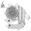
全体を通して同様な番号が同様な要素を指定する図面を詳細に参照すると、図1〜88には、一般的に10で指定される滑動及び回転ヒンジモジュールの第1の実施の形態が、本発明に従い示されている。ヒンジモジュール10は、固定式チャンネルブラケット12を具備しており、チャンネルブラケット12は、車両(車両の計器パネルの一部45が図示される)又は対象物(図示されない)に固定されており、車両又は対象物において、ヒンジモジュール10が使用される。好適には、2つの固定式ブラケット12が設けられるが、2つの固定式ブラケットより多くのものあるいはより少ないものが設けられることは、本発明の精神内及び範囲内に含まれる。2つの固定式ブラケット12は、固定式ブラケット12がお互いに対して概略平行であるように車両又は対象物に搭載され、固定式ブラケット12の前部12aが同じ方向を向くように同様に方向付けられる。スライダー14は、各固定式ブラケット12内に滑動可能に搭載される。各スライダー14は、対応する固定式ブラケット12の前部12aから矢印Aの方向で外方向に滑ることが好ましく、スライダー14は、スライダー14の長さの大部分が固定式ブラケット12内に配置される、収縮(引き込み)位置と、スライダー14の長さの大部分が固定式ブラケット12の前部12aから外方向に伸張する、伸張位置と、を有しており、収縮位置では、各スライダー14の前端部14aだけが、各固定式ブラケット12の前部12aから外方向に伸張する。
Referring now in detail to the drawings in which like numerals designate like elements throughout, FIGS. 1-88 illustrate a first embodiment of a sliding and rotating hinge module, generally designated 10. Is shown according to. The
図1〜88を参照すると、一定力のバネ24はドラム18に対して、一方の端部において固定されることが好ましく、ドラム18は、各固定式ブラケット12により前部12aの近位で、回転するように支持される。各一定力のバネ24の他方の端部は、スライダー14のそれぞれの一方に取り付けられる。一定力のバネ24は、平らならせん状の板バネであることが好ましい。各一定力のバネ24は、付勢されてそれぞれのドラム18の周囲を包み、一定力のバネ24は、スライダー14が収縮位置に向かって動く際に、ドラム18を包む状態を解く。従って、各一定力のバネ24は、それぞれのスライダー14を伸張位置に向かって付勢する。一定力のバネ24は、一定の力を適用して、固定式ブラケット12から外側にスライダー14を付勢する。各一定力のバネ24は、薄い矩形の帯の形状であり、薄い矩形の帯は、テープのリールの状態で、それぞれのドラム18の周りで、らせん状に数回巻き付けられる。緩衝機構20は、それぞれのスライダー14の滑らかな突然ではない動きのために、それぞれのブラケット12に対して各ドラム18の回転運動を緩衝する。各緩衝機構20は、それぞれのドラム18により形成されるロータ(回転子)と、ステータ(固定子)17とを有しており、ステータ17は、ブラケットの前部12aの付近でそれぞれのブラケット12に対して動かない状態で保持される。
With reference to FIGS. 1-88, the
各ステータ17は、内側スリーブ11と、外側スリーブ13とを有する。各ドラム18は、内側スリーブ15と、外側スリーブ19とを有する。ステータ17の内側スリーブは、ドラム18の内側スリーブ内に収容される。ステータ17の内側スリーブは、ドラム18を通り完全に伸張する。ステータ17の外側スリーブは、ドラム18の内側スリーブと外側スリーブとの間に収容される。各一定力のバネ24は、それぞれのドラム18の外側スリーブの周囲を包む。各ステータとドラムアセンブリは、それぞれブラケットの前部12aにおいて、一対のフランジ間に配置される。それぞれのシャフト23は、ステータ17の内側スリーブ及びそれぞれのブラケット12の前部12aにおける一対のフランジの各々を通過して、それぞれのブラケット12の前部12aにおける一対のフランジ間に各ステータとドラムアセンブリを保持する。各ステータ17は、2つの突起21を有しており、突起21は、それぞれのブラケット12の前部におけるフランジの内の1つにおける溝25に係合しており、それによりステータ17とそれぞれのブラケット12との間における相対的回転を防止する。ドラム18は、それぞれのステータ17とそれぞれブラケット12に対して回転可能である。緩衝グリースは、ドラム18の内側及び外側スリーブと、ステータ17の内側及び外側スリーブとの対向する表面間に配置されて、それぞれのステータ17とそれぞれのブラケット12に対する各ドラム18の回転を緩衝するので、それぞれのブラケット12に対してそれぞれのスライダー14の動きを緩衝し、それによりスライダー14を実質的に一定の突然ではなく且つ滑らかな動きで、固定式ブラケット12から外側に伸張させる。
Each
例示の実施の形態において、ブラケット12に対するスライダー14の動きの追加的緩衝は、外側のスリーブを有するカバー27により提供されており、外側のスリーブは、それぞれの一定力のバネ24の最も外側のコイルを少なくとも部分的に囲む。各カバー27がそれぞれのドラム18の周囲を包み、ブラケット12に対するスライダー14の直線的動きを更に緩衝する際に、各カバー27は時々、それぞれの一定力のバネ24に摩擦的に係合する。カバー27と一定力のバネ24との間の摩擦的係合は、収縮位置から伸張位置へのスライダー14の直線的動きの最初のフェーズ(段階)において通常発生する。動きのこのフェーズにおいて、スライダー14の動きは、ドラム18が緩衝機構20の作用(働き)により、遅れずについて行くのには速すぎる。従って、一定力のバネ24は、ドラム18に対して半径方向外側に膨張し、カバー27に摩擦的に係合する。この摩擦係合及び一定力のバネ24の半径方向の膨張の制限は、この初期のフェーズにおいて、スライダー14の直線的動きを減速して緩衝する。各カバー27は、それぞれブラケット12に対して静止する。各カバー27は、それぞれのブラケット12の前部12aにおける一対のフランジの間に配置される。それぞれのシャフト23はまた、カバー27を通過して、それぞれのブラケット12の前部12aにおける一対のフランジの間で各カバー27を保持する。各カバー27は、それぞれのブラケット12のフランジに対向するフランジ内の溝31に係合する、2つの突起29を有しており、ブラケット12は、ステータ17の突起21に係合しており、それによりカバー27とそれぞれのブラケット12との間の相対的回転を防止する。
In the illustrated embodiment, additional cushioning of the
引き出し(ドロワー)16は、スライダー14間、結局固定式ブラケット12間に配置されており、スライダー14に固定されて、スライダーと共に滑動する。引き出し16は一般的に、スライダー14の前端部14aの近位にあるスライダー14に固定されている、前端部16aによりU形状で形成されることが好ましい。L形状の耳部16bは、引き出し16の背部の近位から上方向で外側に伸張しており、スライダー14に取り付けられる。耳部16bは、固定式ブラケット12の頂部表面に効果的に載って、引き出し16の背部を支持する。
The drawers (drawers) 16 are disposed between the
回転アーム26は、スライダー14の前端部14aに回転可能に係合することが好ましい。回転アーム26は、第1の垂直な位置から第2の位置に、矢印Bの方向で回転しており、それ(回転アーム26)は、ヒンジモジュール10から外側に旋回する。回転アーム26は、スライダー14の前端部14a内に配置される、捩りバネ28により第2の位置に向かって付勢されることが好ましい。回転アーム26は、緩衝グリースを有するシリンダ内シリンダジョイント(継手)により前端部14aに取り付けられることが好ましく、緩衝グリースは、回転アーム26の接近して離間する表面と前端部14aとの間に配置されて、回転アーム26の回転を緩衝可能にする。
The
図解の例において、スライダー14の前端部14aは、内部スリーブ33と外壁35とを有する円筒状の空洞を具備する。各アーム26は、内部柱(ポスト)37と外壁39とを有する、一方の端部に円筒状の空洞を具備する。各アーム26の内部柱37は、それぞれのスライダー14の内部スリーブ33内に収容される。各アーム26の外壁39は、それぞれのスライダー14の外壁35内に収容される。各捩りバネ28のコイルは、それぞれのスライダー14の内部スリーブ33と、それぞれのアーム26の外壁39との間に収納される。各捩りバネ28の軸方向に突き出る尾部は、スライダー14の円筒状の空洞内の孔及びアーム26の円筒状の空洞内の孔にそれぞれ係合して、それぞれのアーム26を第2の位置又は展開位置に向かって付勢する。それぞれのスライダー14に対するアーム26の回転の粘性緩衝作用は、各アーム26の外壁39とそれぞれのスライダー14の外壁35との接近して離間する表面間に配置される緩衝グリースと、各アーム26の内部柱37とそれぞれのスライダー14の内部スリーブ33との接近して離間する表面間に配置される緩衝グリースとにより提供される。
In the illustrated example, the
この構成は好適であるが、異なる構成が使用されることは、それらが本明細書に開示される状態で実施可能であれば、本発明の精神と範囲内にある。突起26bは、各回転アーム26の側部から内側に伸張することが好ましい。表示スクリーン(図示されない)又は別の対象物(図示されない)は、回転アーム26に取り付けられて、それらと共に回転することが意図される。
While this configuration is preferred, the use of different configurations is within the spirit and scope of the present invention if they can be practiced as disclosed herein. The
ヒンジモジュール10は、スライダー14が収縮位置にあって回転アーム26が第1の位置にある、収容位置と、スライダー14が伸張位置にあって回転アーム26が第2の位置にある、展開位置とを有することが好ましい。一定力のバネ24及び捩りバネ28は、ヒンジモジュール10を展開位置に付勢する。
The
ラッチ32は、ヒンジモジュール10を、収容位置に保持するように使用されることが好ましい。ラッチ32は、各固定式ブラケット12の前部12aに好適にはその頂部の近位で回転可能に設置される、フック32aを具備して、各回転アーム26の突起26bに係合し、ヒンジモジュール10を収容位置に保持することが好ましい。フック32aは、固定式ブラケット12に実質的に垂直な方向において、フック32a間で伸張する、シャフト32bにより回転可能に接続させられることが好ましい。タブ32cは、シャフト32bに固定されることが好ましい。
The latch 32 is preferably used to hold the
この様にして、タブ32cの操作により、シャフト32bの回転が生じており、その結果、フック32aにより、回転アーム26の突起26bを開放して、ヒンジモジュール10を収縮(引き込み)位置から開放する。捩りバネ32dは、突起26bと係合するようにフック32aを付勢する。好適には、ボタン(図示されない)又はレバー(図示されない)等のインターフェース(図示されない)に対して、車両内において使用者が接近可能であり、インターフェースは、タブ32cに接続させられるので、ボタンの押圧(押すこと)又はレバーの回転により、タブ32cの回転が生じる。この様にして、使用者は、ヒンジモジュール10を開放可能である。上記で検討されたラッチ32は、好ましいが、しかしヒンジモジュール10を収縮位置に保持するように機能可能であるとの条件の下で、別の装置がヒンジモジュール10と共に使用されることは、本発明の精神及び範囲内である。
In this manner, the
上記で検討されたヒンジモジュール10の構成要素は、重合体(ポリマー)材料及び金属材料の内の1つから形成されることが好ましい。固定式ブラケット12及び回転アーム26は、それだけに限定されないが例えば、鉛等の鋳物金属から製作されても良い。一定力のバネ24及びアームバネ28は、それだけに限定されないが例えば、一定力のバネ24用のステンレス鋼及びアームバネ28用のピアノ線等の金属により製作されることが好ましい。引き出し16、フック32a、シャフト32b及びタブ32cはまた、それだけに限定されないが例えば、引き出し16、フック32a及びタブ32c用の鉛メッキ鋼及びシャフト32b用のニッケルメッキ鋼等の金属により製作されることが好ましい。最後に、スライダー14は、それだけに限定されないが例えば、ガラスで充填されたデルリン等のプラスティック等の重合体材料により製作されることが好ましいが、しかし例えば、スライダー14は、もし必要であれば、鋳物鉛等の金属から製作することもできる。これらの材料は好適であるが、しかし構成要素が異なる材料により製作されることは、構成要素が本明細書に記載された状態でやはり機能可能であることの条件の下で、本発明の精神及び範囲内である。
The components of the
使用において、ヒンジモジュール10は、計器盤内の航行システム(装置)(図示されない)と共に使用するために自動車内に配設されることが好ましい。固定式ブラケット12は、車両の計器盤(図示されない)に実質的に固定され、その内に配設されており、航行システムの表示スクリーンは、回転アーム26に取り付けられる。通常の作動において、ヒンジモジュール10は、収縮位置に保持されるので、表示スクリーンは実質的に垂直方向を向き、計器盤の前部と同一面にある。使用者がヒンジモジュール10を開けようとする(例えば、航行システム内においてデータディスク(図示されない)を変更するために)場合に、使用者は、インターフェースボタン又はレバーを作動させてラッチ32を外す。スライダー14はその後、一定力のバネ24により、伸張位置に向かって矢印Aの方向で外方向に自動的に押されて、順に引き出し16を外方向に滑動させる。
In use, the
この地点において、スライダー14及び引き出し16は、外方向に滑り続け、その一方で回転アーム26は、表示スクリーン47がスライダー14に概略垂直である、第1の位置から、矢印Bの方向で、第2の位置に向かって回転して、スライダー14に概略平行な向きに表示スクリーンを設置可能であり、それによりヒンジモジュール10を展開位置に設置し、使用者が航行システムに接近することを可能にする。ヒンジモジュール10を収容位置に戻すように設置するために、使用者は、表示スクリーンに力を作用させて、回転アーム26を第1の位置へ戻すように回転させ、その後スライダー14を収縮位置へ押し、ラッチ32が回転アーム26の突起26bに再係合することを可能にし、ヒンジモジュール10を収容位置に保持する。
At this point, the
このようにして、ヒンジモジュール10は、収容位置から展開位置へモータを使用しないで移動する場合に、比較的一定の回転動と共に、比較的一定の滑動を提供する。航行システムに対して説明されたが、ヒンジモジュール10は、回転動と組み合わされたその様な滑動が望まれる、任意の用途において使用可能であることを認識することが重要である。
In this way, the
本発明は、線形ダンパーの場合のように緩衝グリースが緩衝面から拭われないという利点を有しており、そのことは、緩衝の有効性の損失を生じるかもしれない。また使用者及び、ヒンジモジュール10により支持される電子部品は、皮膚部及び被覆部を汚染可能であるか又は敏感な電子部品を損傷可能である、緩衝グリースから隔離されている。
The present invention has the advantage that the cushioning grease is not wiped off the cushioning surface as is the case with linear dampers, which may result in a loss of cushioning effectiveness. Also, the user and the electronic components supported by the
一定力のバネ24の一端は、所謂ピン41等の成形形態を有するドラム18に固定されており、この端部はまた、ロータ又はドラム18のスロット(長穴)に挿入される(また、この接続部は、構造的な接着テープを使用して実現可能であった)。スライダーの線形運動をダンパーに接続するための別の方法は、スライダー及び回転ダンパーと一体化される、ギアラックとピニオンの設計の合体である。
One end of a
図解の実施の形態におけるドラム18に一定力のバネ24の内側端部を固定することは、スライダー14の自由な線形の移動と、ダンパーロータ又はドラム18の制御された回転動との間の固有の摩擦差異によって重要である。ドラム18とスライダー14との間の摩擦力の差異は、収容位置にある場合に、一定力のバネ24に貯蔵された潜在的エネルギを、アセンブリが作動させられる場合に一様にする。摩擦力のためのこの一様化(一定力のバネ24による運動エネルギへの潜在的エネルギの解放)は、一定力のバネ24の外径を、平衡がスライダー14の軸方向の運動及びドラム18の回転動により確立されるまで増大させる(コイル分離)結果となる。
Fixing the inner end of the
一定力のバネの伸長は、顧客の電子アセンブリ内の制限された空間、あるいは金属製バネが電子回路に接触する可能性により望まれない。一定力のバネの伸長を解決するために、及び電子回路との潜在的接触を防止するために、重合体カバー27は、一定力のバネ24の伸長を抑圧するように工夫された。このカバーはまた、一定力のバネ24の外径コイルにより発生させられる摩擦により、アセンブリの追加的な緩衝の追加的利益を提供しており、一定力のバネの外径コイルは、バネがドラム18の周りを囲むので、重合体カバー27の内径表面に接触する。この追加的なシステム摩擦は、アセンブリの線形的移動の全体的緩衝の優れた調整を可能にすることが望まれる。緩衝された線形運動のこの調整は、製品機能及びサイクル寿命を改善することが望まれる。緩衝率は、間隙の増減、回転する表面面積、流体粘性の緩衝、又は例えば、Oリング等の1つ以上の半径方向のシール要素の追加により調整可能である。
Constant force spring extension is undesirable due to the limited space in the customer's electronic assembly or the possibility of the metal spring contacting the electronic circuit. In order to solve the constant force spring extension and to prevent potential contact with the electronic circuit, the
緩衝運動は、以下のように、スライダー14の軸方向の動きに適用される。フック32aは、使用者による開放機構の作動により、アーム26との係合を外される。これは、一定力のバネ24に貯蔵されたエネルギを解放して、スライダー14を伸張状態に向かって外側に変化させる。バネコイル力は、カバー27の内径の制限まで成長するバネ外径コイルにより、一様化(バネ形状の変化)を生じる(これは、スライダーの初期のサージ(急増)を外側に、一定力のバネ24の一様化まで引き起こしており、少しだけ顕著である)。線形の移動システム摩擦力はその後、一様化されており、ダンパーは、伸張位置及び展開位置に向かって外側への直線動(一定速度)を抑制する一方で、アーム26は、表示器を展開位置に向かって前方に回転させる。
The buffering motion is applied to the axial movement of the
ヒンジアセンブリは、作動する場合に表示パネルの回転動を起動させるのに必要な回転エネルギを貯蔵するように捩りバネ28を使用する。アーム26の表面が、緩衝流体(例えば、高粘性緩衝グリース)で充填された空洞を有する、スライダー14に、直径が接近した状態で適合することにより、アーム26の回転動を緩衝する。アーム26の回転の抑制及びアーム26のスライダーへの取り付けは、スライダー14への及びアーム26に追加されるフランジ43へのスナップフィット(適正嵌合)のタブの幾何学形状部の追加により実現されることが好ましい。例えば、Oリング等の半径方向のシールは、アーム/スライダーヒンジ旋回部(ピボット)に追加されて、緩衝流体の保持を改善可能で、必要であれば、追加的な摩擦力を追加可能である。
The hinge assembly uses a
変更が上記の実施の形態に対して、その広範な発明的概念から逸脱しないで実施されることが、当業者により認識される。従って、本発明は、開示された特定の実施の形態に制限されず、本発明の精神及び範囲内で修正形態をカバーすることを意図することが理解される。 Those skilled in the art will recognize that changes may be made to the above embodiments without departing from the broad inventive concept thereof. Accordingly, it is to be understood that the invention is not limited to the particular embodiments disclosed, but is intended to cover modifications within the spirit and scope of the invention.
Claims (6)
車両に固定するために適応される少なくとも1つのブラケット(12)と、
前記ブラケット(12)内に設置されていて且つ収縮位置と伸張位置との間で前記ブラケット(12)に対する滑動のために支持される、スライダー(14)と、
前記ブラケット(12)により回転可能に支持されるドラム(18)と、
前記ドラム(18)に一方の端部で取り付けられ且つ前記スライダー(14)に別の端部で取り付けられる、一定力のバネ(24)であって、前記一定力のバネ(24)は、付勢されて前記ドラム(18)の周囲を包み、前記スライダー(14)が前記収縮位置に向かって移動する際に、前記ドラム(18)を包む状態から解放されており、前記スライダー(14)を前記伸張位置に向かって付勢する、一定力のバネ(24)と、
前記スライダー(14)の突然ではない動きのために、前記ブラケットに対する前記ドラム(18)の回転動を緩衝するための緩衝機構(20)と、
前記スライダー(14)に回転可能に取り付けられる、支持部材(26)であって、少なくとも前記スライダー(14)が前記伸張位置にある場合に、第1の位置と第2の位置との間で前記スライダー(14)に対して回転可能に移動可能である、支持部材(26)と、
前記スライダー(14)を前記収縮位置に選択可能に保持するために具備されるラッチ(32)と、
前記ブラケット(12)に取り付けられるカバー(27)であって、前記一定力のバネ(24)の最外側のコイルを少なくとも部分的に囲む、外側のスリーブを有するカバー(27)と、
を具備するヒンジモジュールにおいて、
前記カバー(27)が前記ドラム(18)の周囲を包んで更に前記ブラケット(12)に対する前記スライダー(14)の直線的動きを緩衝する際に、前記カバー(27)は時々、前記一定力のバネ(24)に摩擦的に係合しており、
前記ラッチは、前記支持部材に係合して前記スライダーを前記収縮位置に保持することが出来、
前記支持部材は、前記スライダーに対して前記第2の位置に向かってバネ付勢され、前記第2の位置は、前記支持部材(26)の展開位置に相当し、
前記スライダーに対して前記支持部材の回転動を緩衝するための緩衝手段を更に具備する、ことを特徴とするヒンジモジュール。 Sliding and rotating hinge module,
At least one bracket (12) adapted to be secured to the vehicle;
A slider (14) installed in the bracket (12) and supported for sliding relative to the bracket (12) between a retracted position and an extended position;
A drum (18) rotatably supported by the bracket (12);
A constant force spring (24) attached to the drum (18) at one end and attached to the slider (14) at another end, the constant force spring (24) being attached When the slider (14) moves toward the contracted position, the drum (18) is released from the state of wrapping the drum (18). A constant force spring (24) biasing toward the extended position;
A buffer mechanism (20) for buffering rotational movement of the drum (18) relative to the bracket for non-sudden movement of the slider (14);
A support member (26) rotatably attached to the slider (14), wherein at least the slider (14) is between the first position and the second position when the slider (14) is in the extended position. A support member (26) that is rotatable relative to the slider (14);
A latch (32) provided for selectively holding the slider (14) in the retracted position;
A cover (27) attached to the bracket (12), the cover (27) having an outer sleeve at least partially surrounding the outermost coil of the constant force spring (24);
In a hinge module comprising:
As the cover (27) wraps around the drum (18) and further cushions the linear movement of the slider (14) relative to the bracket (12), the cover (27) sometimes has the constant force. Frictionally engaging the spring (24);
The latch can be engaged with the support member to hold the slider in the contracted position,
The support member is spring-biased toward the second position with respect to the slider, and the second position corresponds to a deployed position of the support member (26) ,
The hinge module according to claim 1, further comprising buffer means for buffering rotational movement of the support member with respect to the slider.
シャフト(23)と、
前記ドラム(18)により形成されるローターと、
前記ブラケット(12)の前部(12a)の付近で、前記ブラケット(12)に対して動かない状態で保持される、ステータ(17)と、を具備する滑動と回転ヒンジモジュールにおいて、
前記ステータ(17)は、内側スリーブ(11)と、外側スリーブ(13)とを有しており、
前記ドラム(18)は、内側スリーブ(15)と、外側スリーブ(19)とを有しており、
前記ステータ(17)の前記内側スリーブは、前記ドラム(18)の前記内側スリーブ内に収容されており、
前記ステータ(17)の前記内側スリーブは、前記ドラム(18)を通り完全に伸張しており、
前記ステータ(17)の前記外側スリーブは、前記ドラム(18)の前記内側スリーブと前記ドラム(18)の前記外側スリーブとの間に収容されており、
前記一定力のバネ(24)は、前記ドラム(18)の前記外側スリーブの周囲を包んでおり、
前記ステーター(17)及び前記ドラム(18)は、前記ブラケット(12)の前記前部(12a)における一対のフランジ間に配置される、ドラムアセンブリを形成しており、
前記シャフト(23)は、前記ステーター(17)の前記内側スリーブ及び前記ブラケット(12)の前記前部(12a)における前記一対のフランジの各々を通り通過して、前記ブラケット(12)の前記前部(12a)における前記一対のフランジ間において前記ステーター(17)とドラムアセンブリを保持しており、
前記ステーター(17)は、2つの突起(21)を有しており、前記2つの突起(21)は、前記ブラケット(12)の前記前部(12a)における前記一対のフランジの内の1つにおける溝(25)に係合しており、それにより、前記ステーター(17)と前記ブラケット(12)との間における相対的な回転を防止しており、前記ドラム(18)は、前記ステーター(17)と前記ブラケット(12)に対して回転可能であり、
緩衝グリースは、前記ドラム(18)の前記内側スリーブと前記ドラム(18)の前記外側スリーブと前記ステーター(17)の前記内側スリーブと前記ステーター(17)の前記外側スリーブとのそれぞれの対向する表面の間に配置されて、前記ステーター(17)と前記ブラケット(12)に対する前記ドラム(18)の回転を緩衝し、それにより、前記ブラケット(12)に対する前記スライダー(14)の滑動を緩衝する、ことを特徴とする請求項1に記載の滑動と回転ヒンジモジュール。 The buffer mechanism (20)
A shaft (23);
A rotor formed by the drum (18);
In the vicinity of the front part (12a) of the bracket (12), a sliding and rotating hinge module comprising a stator (17) held stationary with respect to the bracket (12),
The stator (17) has an inner sleeve (11) and an outer sleeve (13),
The drum (18) has an inner sleeve (15) and an outer sleeve (19),
The inner sleeve of the stator (17) is housed in the inner sleeve of the drum (18);
The inner sleeve of the stator (17) extends completely through the drum (18);
The outer sleeve of the stator (17) is housed between the inner sleeve of the drum (18) and the outer sleeve of the drum (18);
The constant force spring (24) wraps around the outer sleeve of the drum (18);
The stator (17) and the drum (18) form a drum assembly disposed between a pair of flanges in the front portion (12a) of the bracket (12);
The shaft (23) passes through each of the pair of flanges in the inner sleeve of the stator (17) and the front portion (12a) of the bracket (12), and the front of the bracket (12). Holding the stator (17) and the drum assembly between the pair of flanges in the portion (12a);
The stator (17) has two protrusions (21), and the two protrusions (21) are one of the pair of flanges in the front portion (12a) of the bracket (12). Is engaged with the groove (25), thereby preventing relative rotation between the stator (17) and the bracket (12), and the drum (18) 17) and rotatable with respect to the bracket (12),
The shock absorbing grease is formed on each of the opposing surfaces of the inner sleeve of the drum (18), the outer sleeve of the drum (18), the inner sleeve of the stator (17) and the outer sleeve of the stator (17). Between the stator (17) and the bracket (12) to buffer the rotation of the drum (18), thereby buffering the sliding of the slider (14) relative to the bracket (12), The sliding and rotating hinge module according to claim 1.
Applications Claiming Priority (3)
| Application Number | Priority Date | Filing Date | Title |
|---|---|---|---|
| US89103907P | 2007-02-21 | 2007-02-21 | |
| US60/891,039 | 2007-02-21 | ||
| PCT/US2008/054610 WO2008103846A2 (en) | 2007-02-21 | 2008-02-21 | Sliding and rotating hinge module |
Publications (2)
| Publication Number | Publication Date |
|---|---|
| JP2010519116A JP2010519116A (en) | 2010-06-03 |
| JP5410995B2 true JP5410995B2 (en) | 2014-02-05 |
Family
ID=39705382
Family Applications (1)
| Application Number | Title | Priority Date | Filing Date |
|---|---|---|---|
| JP2009550626A Expired - Fee Related JP5410995B2 (en) | 2007-02-21 | 2008-02-21 | Sliding and rotating hinge module |
Country Status (5)
| Country | Link |
|---|---|
| US (1) | US8234752B2 (en) |
| JP (1) | JP5410995B2 (en) |
| CN (1) | CN101680255B (en) |
| DE (1) | DE112008000441T5 (en) |
| WO (1) | WO2008103846A2 (en) |
Families Citing this family (27)
| Publication number | Priority date | Publication date | Assignee | Title |
|---|---|---|---|---|
| US9375100B2 (en) | 2004-02-03 | 2016-06-28 | Rtc Industries, Inc. | Product securement and management system |
| US8047385B2 (en) | 2004-02-03 | 2011-11-01 | Rtc Industries, Inc. | Product securement and management system |
| US11375826B2 (en) | 2004-02-03 | 2022-07-05 | Rtc Industries, Inc. | Product securement and management system |
| US9706857B2 (en) | 2004-02-03 | 2017-07-18 | Rtc Industries, Inc. | Product securement and management system |
| US8347462B2 (en) * | 2005-08-01 | 2013-01-08 | Southco, Inc. | Sliding and rotating hinge module |
| WO2007106077A2 (en) * | 2006-03-02 | 2007-09-20 | Southco, Inc. | Drop-in damped hinge module |
| TWI413037B (en) * | 2007-06-15 | 2013-10-21 | Creator Technology Bv | Electronic device with a variable angulation of a flexible display |
| US20100059040A1 (en) * | 2008-09-09 | 2010-03-11 | Timothy Scott Shaffer | Vent system for a cooking appliance |
| JP5944095B2 (en) * | 2010-07-26 | 2016-07-05 | 三菱製鋼株式会社 | Switchgear |
| US8250711B1 (en) * | 2011-04-27 | 2012-08-28 | Lianhong Art Co., Ltd. | Space-saving slide cover lifting structure |
| US8559623B2 (en) * | 2011-06-09 | 2013-10-15 | Lianhong Art Co., Ltd. | Double sliding stability space-saving slide cover lifting structure |
| US8713757B2 (en) * | 2011-06-25 | 2014-05-06 | Lianhong Art Co., Ltd. | Slide cover lifting structure |
| CN103085728B (en) * | 2011-11-08 | 2017-03-01 | 现代摩比斯株式会社 | On-board screen driving means |
| US9010852B1 (en) * | 2011-12-19 | 2015-04-21 | TIMCO Aviation Services | In-arm monitor seat |
| TWI462682B (en) * | 2012-01-12 | 2014-11-21 | Wistron Corp | Connecting mechanism and related electronic device |
| ITMI20130044A1 (en) * | 2013-01-15 | 2014-07-16 | Faringosi Hinges Srl | HINGE |
| GB2513161A (en) * | 2013-04-17 | 2014-10-22 | Bentley Motors Ltd | Display mounting screen |
| CN106459871A (en) * | 2014-05-21 | 2017-02-22 | 卡尤迪生物科技(北京)有限公司 | Thermal cycler lid configuration and use thereof |
| US9409522B2 (en) | 2014-08-21 | 2016-08-09 | Ford Global Technologies, Llc | Moving axis compartment door |
| GB2524132B (en) | 2014-10-16 | 2016-03-16 | Bentley Motors Ltd | Display screen mount |
| US9796314B2 (en) | 2015-08-13 | 2017-10-24 | Ford Global Technologies Llc | Track cover for moving axis compartment door |
| AU2015419026B2 (en) * | 2015-12-29 | 2020-07-23 | Xiaoyu Guo | Pallet displacement system for a pallet storage assembly |
| TWI713433B (en) * | 2018-12-18 | 2020-12-11 | 仁寶電腦工業股份有限公司 | Expansion hinge and electronic deivce having the same |
| US11045016B2 (en) * | 2018-12-20 | 2021-06-29 | Process Retail Group, Inc. | Bearing pusher assembly, and product display including a bearing pusher assembly |
| CN110254362B (en) * | 2019-06-18 | 2021-01-19 | 浙江吉利控股集团有限公司 | Adjustable automobile central control large screen assembly |
| US11470961B2 (en) | 2020-09-29 | 2022-10-18 | Adrian Steel Company | Vehicle shelf system and method of use |
| CN113335193A (en) * | 2021-07-01 | 2021-09-03 | 上海卓迈汽车技术服务有限公司 | Display screen telescopic rotating mechanism |
Family Cites Families (29)
| Publication number | Priority date | Publication date | Assignee | Title |
|---|---|---|---|---|
| US2710782A (en) * | 1951-08-23 | 1955-06-14 | Marc E Chaft | Pull out typewriter supports |
| EP0223940A1 (en) * | 1982-01-20 | 1987-06-03 | idn inventions and development of novelties ag | Storage container for magnetic tape cassettes or other recording media |
| JPH0240531B2 (en) * | 1982-01-28 | 1990-09-12 | Katsuyama Kinzoku Kogyo | ANZENBERUTONORITORAKUTA |
| US4625657A (en) * | 1984-05-15 | 1986-12-02 | Weber-Knapp Company | Adjustable keyboard supporting mechanism |
| US4607884A (en) * | 1984-08-06 | 1986-08-26 | Chrysler Corporation | Vehicle easy entry seat latching mechanism |
| US4764075A (en) * | 1986-04-22 | 1988-08-16 | Safetech Pty. Ltd. | Load elevator |
| JPH0742999B2 (en) * | 1986-08-05 | 1995-05-15 | 株式会社ニフコ | Oil type damper |
| US4836482A (en) * | 1986-08-11 | 1989-06-06 | Detroit Bracket Company, Inc. | Hinged support bracket for a radar detector or like device |
| US5257767A (en) * | 1990-06-13 | 1993-11-02 | Waterloo Furniture Components, Ltd. | Adjustable support mechanism for a keyboard platform |
| JP2945719B2 (en) * | 1990-06-19 | 1999-09-06 | 株式会社ニフコ | Drawer |
| US5294087A (en) * | 1991-10-18 | 1994-03-15 | Engineered Data Products, Inc. | Adjustable keyboard holder for computer workstation |
| US5847685A (en) * | 1992-08-19 | 1998-12-08 | Alpine Electronics, Inc. | Vehicle-mounted display mechanism |
| US5513579A (en) * | 1993-07-16 | 1996-05-07 | Waterloo Furniture Components, Ltd. | Adjustable computer keyboard support mechanism |
| US5881984A (en) * | 1997-06-20 | 1999-03-16 | Lin; Chin-Chih | Dimensional adjusting device for computer keyboards racks |
| US6125030A (en) * | 1998-08-07 | 2000-09-26 | Lear Donnelly Overhead Systems L.L.C. | Vehicle overhead console with flip down navigation unit |
| US6270047B1 (en) * | 1998-11-06 | 2001-08-07 | Compx International Inc. | Keyboard tilt mechanism |
| TW375010U (en) * | 1999-03-15 | 1999-11-21 | Chin-Chih Lin | Adjustment structure for the keyboard drawer |
| DE60124963T2 (en) * | 2000-08-22 | 2007-09-06 | Matsushita Electric Industrial Co., Ltd., Kadoma | fastening device |
| US6464089B1 (en) * | 2001-05-11 | 2002-10-15 | Vulcan Spring & Manufacturing Company | Adjustable spring-driven pusher device for a merchandise dispenser |
| US6871384B2 (en) * | 2001-05-11 | 2005-03-29 | Cema Technologies, Inc. | Hinge assembly for rotatably mounting a display to a surface |
| US6909408B2 (en) * | 2001-12-20 | 2005-06-21 | Bendix Commercial Vehicle Systems Llc | Mounting assembly for night vision display unit |
| US7047890B2 (en) * | 2002-12-27 | 2006-05-23 | Jeffrey Korber | Integrated flat panel workstation system |
| US6832862B2 (en) * | 2003-02-28 | 2004-12-21 | Eastman Kodak Company | System for opening and closing a resealable cartridge |
| US7010833B2 (en) * | 2003-07-18 | 2006-03-14 | Carlos Duarte | Slide hinge for spa cover |
| CN2698940Y (en) * | 2004-05-25 | 2005-05-11 | 耐亚科技有限公司 | Cabinet hinge device with buffer and retractable cover |
| CN2740735Y (en) * | 2004-06-09 | 2005-11-16 | 王祖雷 | Buffered closing device of hinge door |
| CN2780938Y (en) * | 2005-04-28 | 2006-05-17 | 黄耀南 | Spring-oil damp hinge core |
| US8347462B2 (en) * | 2005-08-01 | 2013-01-08 | Southco, Inc. | Sliding and rotating hinge module |
| US7626357B2 (en) * | 2007-02-07 | 2009-12-01 | Eveready Battery Co., Inc. | Battery charger having a spring loaded plunger contact mechanism |
-
2008
- 2008-02-21 CN CN200880005735.6A patent/CN101680255B/en active Active
- 2008-02-21 DE DE112008000441T patent/DE112008000441T5/en not_active Withdrawn
- 2008-02-21 JP JP2009550626A patent/JP5410995B2/en not_active Expired - Fee Related
- 2008-02-21 WO PCT/US2008/054610 patent/WO2008103846A2/en active Application Filing
- 2008-02-21 US US12/035,303 patent/US8234752B2/en active Active
Also Published As
| Publication number | Publication date |
|---|---|
| US8234752B2 (en) | 2012-08-07 |
| WO2008103846A2 (en) | 2008-08-28 |
| US20080196201A1 (en) | 2008-08-21 |
| CN101680255B (en) | 2013-08-21 |
| CN101680255A (en) | 2010-03-24 |
| WO2008103846A3 (en) | 2008-10-09 |
| JP2010519116A (en) | 2010-06-03 |
| DE112008000441T5 (en) | 2010-03-04 |
Similar Documents
| Publication | Publication Date | Title |
|---|---|---|
| JP5410995B2 (en) | Sliding and rotating hinge module | |
| US8347462B2 (en) | Sliding and rotating hinge module | |
| EP1862723B1 (en) | Monitor stand | |
| EP3049885B1 (en) | Frictional hinge for electronic devices | |
| US20120229964A1 (en) | Support mechanism and electronic device using same | |
| US7192072B2 (en) | Movable panel assembly | |
| CN106536283A (en) | A pivot assembly for a vehicle external rear vision device and a pivot tie therefore | |
| JP4559816B2 (en) | Display device | |
| CN109204174A (en) | A kind of clamp bracket | |
| CN107269144B (en) | World hinge with closed buffer structure | |
| JP4912183B2 (en) | Movable body motion control device and console box | |
| JP2010112052A (en) | Door body moving device | |
| JP3152121B2 (en) | Door opening and closing device | |
| JP2010007696A (en) | Damper device | |
| US8146116B2 (en) | Disk device having a clamper restricting member | |
| US8156511B2 (en) | Disc apparatus | |
| US20130255155A1 (en) | Cover assembly and electronic device using the same | |
| JP2002070907A (en) | Rotary damper | |
| KR100921298B1 (en) | Vehicle Glove Box Switchgear | |
| JP5393211B2 (en) | In-vehicle disk unit | |
| NL1008809C1 (en) | Decoration for round frame | |
| JP6373683B2 (en) | sunshade | |
| KR100633879B1 (en) | Cassette door mounting structure of cassette player | |
| JP2000238819A (en) | Lid open/close device | |
| JP2001153165A (en) | Moment generating means and display device using moment generating means |
Legal Events
| Date | Code | Title | Description |
|---|---|---|---|
| A621 | Written request for application examination |
Free format text: JAPANESE INTERMEDIATE CODE: A621 Effective date: 20110209 |
|
| A977 | Report on retrieval |
Free format text: JAPANESE INTERMEDIATE CODE: A971007 Effective date: 20120711 |
|
| A131 | Notification of reasons for refusal |
Free format text: JAPANESE INTERMEDIATE CODE: A131 Effective date: 20120717 |
|
| A601 | Written request for extension of time |
Free format text: JAPANESE INTERMEDIATE CODE: A601 Effective date: 20121016 |
|
| A602 | Written permission of extension of time |
Free format text: JAPANESE INTERMEDIATE CODE: A602 Effective date: 20121023 |
|
| A521 | Request for written amendment filed |
Free format text: JAPANESE INTERMEDIATE CODE: A523 Effective date: 20121107 |
|
| A131 | Notification of reasons for refusal |
Free format text: JAPANESE INTERMEDIATE CODE: A131 Effective date: 20130507 |
|
| A521 | Request for written amendment filed |
Free format text: JAPANESE INTERMEDIATE CODE: A523 Effective date: 20130712 |
|
| A01 | Written decision to grant a patent or to grant a registration (utility model) |
Free format text: JAPANESE INTERMEDIATE CODE: A01 Effective date: 20131008 |
|
| A61 | First payment of annual fees (during grant procedure) |
Free format text: JAPANESE INTERMEDIATE CODE: A61 Effective date: 20131107 |
|
| LAPS | Cancellation because of no payment of annual fees |