JP5403007B2 - Linear motor armature and linear motor - Google Patents
Linear motor armature and linear motor Download PDFInfo
- Publication number
- JP5403007B2 JP5403007B2 JP2011170234A JP2011170234A JP5403007B2 JP 5403007 B2 JP5403007 B2 JP 5403007B2 JP 2011170234 A JP2011170234 A JP 2011170234A JP 2011170234 A JP2011170234 A JP 2011170234A JP 5403007 B2 JP5403007 B2 JP 5403007B2
- Authority
- JP
- Japan
- Prior art keywords
- armature
- auxiliary teeth
- linear motor
- detection unit
- teeth
- Prior art date
- Legal status (The legal status is an assumption and is not a legal conclusion. Google has not performed a legal analysis and makes no representation as to the accuracy of the status listed.)
- Expired - Fee Related
Links
Images


Landscapes
- Linear Motors (AREA)
Description
本発明は、リニアモータの電機子およびリニアモータに関する。 The present invention relates to a linear motor armature and a linear motor.
従来、電動機の一種として、磁極同士の吸引・反発力を利用することで、固定子に沿って可動子を直線的に移動させるリニアモータが知られている。 Conventionally, as a kind of electric motor, a linear motor that moves a mover linearly along a stator by using attraction / repulsive force between magnetic poles is known.
かかるリニアモータでは、可動子の位置を検出するためのセンサとして、ホールセンサ等の検出部が可動子に設けられる場合がある。かかる検出部は、たとえば、可動子のストローク方向端に設けられる(特許文献1参照)。 In such a linear motor, a detector such as a hall sensor may be provided on the mover as a sensor for detecting the position of the mover. Such a detection unit is provided, for example, at the end of the mover in the stroke direction (see Patent Document 1).
しかしながら、可動子のストローク方向端に検出部を設けることとすると、検出部の長さだけ可動子の可動範囲、すなわち、有効ストロークが短くなるという問題があった。 However, if the detection unit is provided at the end of the mover in the stroke direction, there is a problem that the movable range of the mover, that is, the effective stroke is shortened by the length of the detection unit.
開示の技術は、上記に鑑みてなされたものであって、有効ストロークの減少を抑えることができるリニアモータの電機子およびリニアモータを提供することを目的とする。 The disclosed technology has been made in view of the above, and an object thereof is to provide an armature of a linear motor and a linear motor that can suppress a decrease in effective stroke.
本願の開示するリニアモータの電機子は、主ティースを備える電機子コアと、前記電機子コアのストローク方向端へ設けられた切り欠かれた補助ティースと、前記電機子コアの位置を検出する検出部と、少なくとも前記補助ティースの切り欠かれた端面を露出させた状態で、前記補助ティースをモールドするモールド樹脂とを備え、前記検出部は、前記補助ティースを切り欠いた空間に設けられるとともに、前記補助ティースの前記モールド樹脂から露出した端面に取り付けられる。 An armature of a linear motor disclosed in the present application includes an armature core having a main tooth, a notched auxiliary tooth provided at a stroke direction end of the armature core, and a detection for detecting a position of the armature core. And a mold resin that molds the auxiliary teeth in a state in which the end surface where the auxiliary teeth are cut out is exposed, and the detection unit is provided in a space where the auxiliary teeth are cut out. It attaches to the end surface exposed from the mold resin of the auxiliary teeth .
また、本願の開示するリニアモータは、複数の磁石が並べて配置された界磁部と、前記界磁部に対して対向配置される電機子とを備えたリニアモータであって、前記電機子は、主ティースを備える電機子コアと、前記電機子コアのストローク方向端へ設けられた切り欠かれた補助ティースと、前記電機子コアの位置を検出する検出部と、少なくとも前記補助ティースの切り欠かれた端面を露出させた状態で、前記補助ティースをモールドするモールド樹脂とを備え、前記検出部は、前記補助ティースを切り欠いた空間に設けられるとともに、前記補助ティースの前記モールド樹脂から露出した端面に取り付けられる。 Further, the linear motor disclosed in the present application is a linear motor including a field portion in which a plurality of magnets are arranged side by side, and an armature disposed to face the field portion. An armature core including main teeth, a notched auxiliary tooth provided at an end in a stroke direction of the armature core, a detection unit for detecting a position of the armature core, and at least the notch of the auxiliary tooth. A mold resin that molds the auxiliary teeth with the end face exposed, and the detection unit is provided in a space in which the auxiliary teeth are cut out, and is exposed from the mold resin of the auxiliary teeth. Attached to the end face .
本願の開示するリニアモータの電機子およびリニアモータの一つの態様によれば、有効ストロークの減少を抑えることができる。 According to one aspect of the linear motor armature and the linear motor disclosed in the present application, it is possible to suppress a decrease in effective stroke.
以下に添付図面を参照して、本願の開示するリニアモータの電機子およびリニアモータのいくつかの実施例を詳細に説明する。ただし、これらの実施例における例示で本発明が限定されるものではない。 Exemplary embodiments of a linear motor armature and a linear motor disclosed in the present application will be described below in detail with reference to the accompanying drawings. However, the present invention is not limited to the examples in these examples.
まず、本実施例に係るリニアモータの全体構成について図1A〜図1Cを用いて説明する。図1A〜図1Cは、それぞれ実施例1に係るリニアモータの模式側面図、模式平面図および模式断面図である。なお、図1Bは、図1Aに示すリニアモータをZ軸正方向から見た場合の模式平面図である。また、図1Cは、図1Aに示すA−A’線矢視の模式断面図である。 First, the overall configuration of the linear motor according to the present embodiment will be described with reference to FIGS. 1A to 1C. 1A to 1C are a schematic side view, a schematic plan view, and a schematic cross-sectional view, respectively, of a linear motor according to a first embodiment. 1B is a schematic plan view when the linear motor shown in FIG. 1A is viewed from the positive Z-axis direction. 1C is a schematic cross-sectional view taken along line A-A ′ shown in FIG. 1A.
また、以下では、リニアモータの各構成要素の相対的な位置関係を説明する上で、上下、左右、及び前後で方向を示す場合があるが、各方向の基準は、図1Aに示すように、リニアモータを水平面に設置した場合とする。具体的には、図1A中、X軸の正方向および負方向をそれぞれリニアモータの前方および後方、Y軸の正方向および負方向をそれぞれリニアモータの左方および右方、Z軸の正方向および負方向をリニアモータの上方および下方とする。 In the following, in explaining the relative positional relationship of each component of the linear motor, there are cases where directions are indicated in the vertical direction, the horizontal direction, and the longitudinal direction. The reference for each direction is as shown in FIG. 1A. Suppose that the linear motor is installed on a horizontal plane. Specifically, in FIG. 1A, the positive and negative directions of the X axis are the front and rear of the linear motor, respectively, the positive and negative directions of the Y axis are the left and right directions of the linear motor, and the positive direction of the Z axis, respectively. The negative direction is defined above and below the linear motor.
図1A〜図1Cに示すように、本実施例に係るリニアモータ1は、界磁部10と、電機子20とを備える。なお、本実施例では、界磁部10を固定子とし、電機子20を可動子とする場合について説明する。また、磁極数やスロット数は、図1A〜図1Cに示したものに限定されない。
As shown in FIGS. 1A to 1C, the
界磁部10は、界磁ヨーク11と、永久磁石12とを備える。界磁ヨーク11は、所定方向(ここでは、X軸方向)に沿って伸びる略直方体状の部材であり、たとえば電磁鋼板などの薄板材を複数枚積層して形成されるか、積層ではない単なる板材で形成される。また、永久磁石12は、かかる界磁ヨーク11上に並べて配置される。なお、ここでは、界磁部10が永久磁石12を備える場合について説明するが、界磁部10は、永久磁石12ではなく電磁石を備えてもよい。
The
電機子20は、界磁部10と空隙を介して対向配置される部材であり、界磁部10に沿って直線的に移動する。かかる電機子20は、電機子コア21と、電機子巻線22と、補助ティース23a,23bと、モールド樹脂24と、検出部25とを備える。なお、以下では、電機子20の移動方向、すなわち、X軸の正方向および負方向をストローク方向と呼ぶこととする。
The
電機子コア21は、略直方体状に形成されたヨーク21aと、かかるヨーク21aから界磁部10へ向かって突出した複数の主ティース21bとを備える。なお、電機子コア21は、たとえば電磁鋼板などの薄板材を複数枚積層して形成される。
The
主ティース21b間の空間はスロット21cと呼ばれる。このスロット21cの内周面は絶縁材等で覆われており、スロット21c内に絶縁被覆電線を用いて巻装された電機子巻線22が収められる。なお、各電機子巻線22には、モータ用リード線26が接続される(図1B参照)。
The space between the
補助ティース23a,23bは、推力変動の要因となるコギングを低減するために、電機子コア21のストローク方向両端へそれぞれ設けられる部材である。具体的には、補助ティース23a,23bは、端部がヨーク21aに対して固定されており、かかる端部から界磁部10へ向かって突出している。
The
なお、本実施例では、図1Aに示すように、永久磁石12および補助ティース23a,23b間の間隔が、永久磁石12および主ティース21b間の間隔よりも大きい場合、すなわち、補助ティース23a,23bが主ティース21bよりも短い場合の例を示す。ただし、補助ティース23a,23bの長さは、主ティース21bと同等でもよい。
In this embodiment, as shown in FIG. 1A, when the interval between the
ここで、本実施例に係る電機子20は、補助ティース23a,23bの一部が切り欠かれている。そして、本実施例に係る電機子20は、補助ティース23a,23bの切り欠かれた空間に対して検出部25を設けることで、有効ストロークの低減を抑えることとしているが、かかる点については、図2A〜図2Cを用いて具体的に説明する。
Here, as for the
モールド樹脂24は、電機子コア21、電機子巻線22および補助ティース23a,23bをモールドする樹脂部材である。図1Bおよび図1Cに示すように、モールド樹脂24は、補助ティース23aのY軸負方向に面する端面およびヨーク21aのX軸正方向に面する端面がそれぞれ露出するようにこれらを覆う。なお、補助ティース23aのモールド樹脂24から露出した端面には、検出部25が取り付けられるが、かかる点については図3Aを用いて後述する。
The
検出部25は、界磁部10に対する電機子20の相対位置を検出する検出部である。本実施例において検出部25は、ホールセンサ等の磁界検出部である。リニアモータ1は、かかる検出部25による電機子20の相対位置の検出結果に基づいて、電機子巻線22への通電方向等が制御される。なお、検出部25には、検出部用リード線27が接続される(図1B参照)。
The
かかる検出部25は、図1Bにおいて、補助ティース23aの切り欠かれた空間内に設けられる。これにより、本実施例に係るリニアモータ1は、電機子20の有効ストロークの低減を抑えることができる。
Such a
なお、図1Bに示した例では、検出部25が、補助ティース23aの切り欠かれた空間内に設けられることとしたが、検出部25の配置は、これに限られない。すなわち、検出部25の一部が、補助ティース23aの切り欠かれた空間外に設けられてもよい。例えば、検出部25の一部が、図1BのX方向の負方向に飛び出していてもよい。この場合であっても、検出部25を、補助ティース23aの切り欠かれた空間に対して設けることができるので、電機子20の有効ストロークの低減を抑えることができる。
In the example shown in FIG. 1B, the
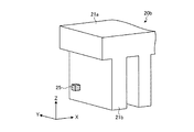
以下では、補助ティース23aおよび検出部25の配置関係について図2A〜図2Cを用いて具体的に説明する。図2A〜図2Cは、それぞれ補助ティース23aおよび検出部25の配置関係を示す模式正面図、模式平面図および模式斜視図である。
Below, the arrangement | positioning relationship between the
図2A〜図2Cに示すように、補助ティース23aは、ストローク方向における一端面から他端面まで、すなわち、X軸負方向側の一端面からX軸正方向側の他端面まで達するように切り欠かれた切欠部100aを備える。
As shown in FIGS. 2A to 2C, the
かかる切欠部100aは、界磁部10と対向する側s1(Z軸負方向側)、界磁部10と対向する側s1に隣接する側s2(Y軸正方向側)および界磁部10と対向する側s1の反対側s3(Z軸正方向側)がそれぞれ開放されている。すなわち、補助ティース23aは、X軸正方向から見て、左側半分が切り欠かれた形状となっている。検出部25は、かかる補助ティース23aの切欠部100aに対して設けられる。
The
ここで、従来の電機子においては、ストローク方向端に検出部を設けることにより、検出部の長さだけ有効ストロークが短くなるという問題があった。特に、かかる問題は、本実施例のように電機子コアのストローク方向端に補助ティースを設ける場合に顕在化し易い。 Here, the conventional armature has a problem that the effective stroke is shortened by the length of the detection unit by providing the detection unit at the end in the stroke direction. In particular, such a problem is easily manifested when an auxiliary tooth is provided at the end of the armature core in the stroke direction as in this embodiment.
そこで、本実施例では、補助ティース23aを切り欠いた空間に対して検出部25を設けることとした。これにより、電機子20のストローク方向の長さのうち電機子コア21以外の部材が占める長さを抑えることができるため、電機子20の推力を維持しつつ、有効ストロークの低減を抑えることができる。
Therefore, in this embodiment, the
また、本実施例において切欠部100aは、界磁部10と対向する側が開放されている。また、検出部25の全部が切欠部100a内に設けられている。このため、検出部25による磁界の検出精度が低下しにくくなる。
Further, in the present embodiment, the
また、本実施例において補助ティース23a,23bは、図1Bに示すように、互いに同一の形状を有し、かつ、Z軸方向から見た場合において電機子コア21の中心に対して点対称に配置されている。このため、補助ティース23a,23bの一部を切り欠いた場合であっても、コギングをバランスよく低減することができる。
Further, in this embodiment, the
また、補助ティース23a,23bは、単に切り欠いただけでなく、切り欠くことによってコギングを低減させる効果が極力低下しないように、切り欠いた形状に応じて長さや厚み等が最適化される。このため、コギング低減の効果を極力維持しつつ、検出部25の設置スペースを確保することができる。
Further, the
なお、検出部25は、補助ティース23aから離れた位置に設けられてもよい。これにより、検出部25が補助ティース23aの影響を受けにくくなるので、検出部25の検出精度が向上する。
In addition, the
なお、本実施例では、検出部25が、磁界検出部であるものとするが、検出部は、磁界検出部以外の検出部であってもよい。たとえば、永久磁石12の電機子20と対向する面に対して所定のマーキングを施し、かかるマーキングを光学的に検知することによって電機子コア21の相対位置を検出する赤外線センサ等を検出部として備えてもよい。
In the present embodiment, the
次に、検出部25の取り付け方向について図3Aを用いて説明する。図3Aは、検出部25の取り付け方法の一例を示す図である。
Next, the attachment direction of the
本実施例に係る検出部25は、ユニット化されており、モールド樹脂24によってモールドされた補助ティース23a,23bに対して検出部25が着脱自在に設けられる。
The
たとえば、図3Aに示すように、補助ティース23aには、モールド樹脂24から露出した端面からY軸負方向に沿ってネジ穴231が形成される。また、検出部25にも同様のネジ穴251が形成される。そして、補助ティース23aのネジ穴231および検出部25のネジ穴251に図示しないネジを挿通させることによって、検出部25を補助ティース23aに対して取り付けることができる。
For example, as shown in FIG. 3A, screw holes 231 are formed in the
このように、検出部25を着脱自在に設けることとすれば、たとえば、検出部25が劣化した場合や故障した場合等に、検出部25を容易に取り替えることができ、電機子20のメンテナンス性を向上させることができる。
As described above, if the
なお、補助ティース23aの切欠部100a(図2A参照)は、界磁部10と対向する側s1だけでなく、界磁部10と対向する側s1に隣接する側s2や界磁部10と対向する側s1の反対側s3も開放されている。このため、検出部25の着脱作業を容易に行うことができる。
The
また、図3Aに示すように、検出部25は、補助ティース23aのうち界磁部10により近い位置に設けられる。これにより、検出部25による磁界の検出精度を高めることができる。
Moreover, as shown to FIG. 3A, the
なお、図3Aでは、検出部25を補助ティース23aに設けることとしたが、検出部25の取り付け方法は、これに限ったものではない。図3Bは、検出部25の取り付け方法の他の一例を示す図である。
In FIG. 3A, the
図3Bに示すように、検出部25は、たとえばヨーク21aに設けてもよい。かかる場合には、モールド樹脂24から露出したヨーク21aの端面からX軸正方向に沿ってネジ穴212を形成し、かかるヨーク21aのネジ穴212および検出部25のネジ穴251の両方に図示しないネジを挿通させればよい。
As shown in FIG. 3B, the
なお、検出部25は、モールド樹脂24中に浮いた状態で設けられてもよい。
Note that the
上述してきたように、本実施例では、補助ティース23aを切り欠いた空間に対して検出部25を設けることとしたため、有効ストロークの低減を抑えることができる。
As described above, in the present embodiment, since the
ところで、補助ティースの切り欠き方や検出部の配置は、実施例1に示した場合に限ったものではない。そこで、実施例2では、補助ティースの切り欠き方および検出部の配置の他の一例について説明する。 By the way, the method of notching the auxiliary teeth and the arrangement of the detection units are not limited to those shown in the first embodiment. Accordingly, in the second embodiment, another example of how to cut out the auxiliary teeth and the arrangement of the detection units will be described.
図4および図5は、補助ティースおよび検出部の配置関係の他の一例を示す模式斜視図である。なお、以下の説明では、既に説明した部分と同様の部分については、既に説明した部分と同一の符号を付し、重複する説明を省略する。 4 and 5 are schematic perspective views illustrating another example of the arrangement relationship between the auxiliary teeth and the detection unit. In the following description, parts that are the same as those already described are given the same reference numerals as those already described, and redundant descriptions are omitted.
図4に示すように、電機子20aは、実施例1に係る補助ティース23aに代えて、補助ティース23a_1を備える。
As illustrated in FIG. 4, the
補助ティース23a_1は、切欠部100bを備える。かかる切欠部100bは、実施例1に係る切欠部100aと同様、補助ティース23a_1のストローク方向における一端面から他端面まで、すなわち、X軸負方向側の一端面からX軸正方向側の他端面まで達するように切り欠かれている。
The auxiliary tooth 23a_1 includes a
また、切欠部100bは、界磁部10と対向する側(Z軸負方向側)と、界磁部10と対向する側の反対側(Z軸正方向側)とがそれぞれ開放されている。このように、補助ティース23a_1は、X軸正方向から見て、真ん中部分が縦に切り欠かれた形状としても構わない。
The
また、かかる場合において、補助ティース23a_1およびヨーク21aは、切欠部100bに面する補助ティース23a_1の端面およびヨーク21aのストローク方向の端面が、それぞれ露出するように図示しないモールド樹脂によってモールドされる。そして、検出部25は、実施例1と同様に、モールド樹脂(図示せず)から露出した補助ティース23a_1またはヨーク21aの端面に着脱自在に取り付けられる。
In such a case, the auxiliary teeth 23a_1 and the
なお、図示を省略するが、電機子20aは、実施例1に係る補助ティース23bに代えて、補助ティース23a_1と同一形状の補助ティースを備える。これらの補助ティースは、実施例1と同様、Z軸方向から見た場合において電機子コア21の中心に対して点対称に配置される。これにより、コギングをバランスよく低減することができる。
Although not shown, the
また、図5に示すように、電機子20bは、電機子コア21のストローク方向両端に設けられた補助ティースのうち一方を全て切り欠き、切り欠いた空間に検出部25を設けることとしてもよい。
Moreover, as shown in FIG. 5, the
なお、図示を省略するが、X軸正方向側に設けられる補助ティースは、切り欠かれていない形状となっている。具体的には、X軸負方向側に設けられる補助ティースは、Y軸方向の幅が主ティース21bとほぼ同一の略直方体状の形状を有する。
In addition, although illustration is abbreviate | omitted, the auxiliary | assistant tooth provided in the X-axis positive direction side becomes a shape which is not cut out. Specifically, the auxiliary teeth provided on the X-axis negative direction side have a substantially rectangular parallelepiped shape whose width in the Y-axis direction is substantially the same as that of the
また、図4、図5において、検出部25は、モールド樹脂24中に浮いた状態で設けられてもよい。
4 and 5, the
また、補助ティースおよび検出部の配置関係の他の一例について図6A〜図6Cを用いてさらに説明する。図6A〜図6Cは、補助ティースおよび検出部の配置関係の他の一例を示す模式斜視図である。 Further, another example of the arrangement relationship between the auxiliary teeth and the detection unit will be further described with reference to FIGS. 6A to 6C. 6A to 6C are schematic perspective views illustrating another example of the arrangement relationship between the auxiliary teeth and the detection unit.
図6Aに示すように、電機子20cが備える補助ティース23a_2は、ストローク方向における一端面から他端面まで貫通する貫通孔を切欠部100cとして備える。このように、切欠部100cは、Z軸方向およびY軸方向のいずれの側も開放されていない貫通孔であってもよい。検出部25は、かかる切欠部100c内に設けられる。
As shown in FIG. 6A, the auxiliary teeth 23a_2 included in the
また、図6Bに示すように、電機子20dが備える補助ティース23a_3は、切欠部100dを備える。かかる切欠部100dは、ストローク方向における一端面から他端面まで達するように切り欠かれ、かつ、界磁部10と対向する側(Z軸負方向側)が開放されている。このように、切欠部100dは、界磁部10と対向する側だけが開放された形状であってもよい。検出部25は、かかる切欠部100d内に設けられる。
Moreover, as shown to FIG. 6B, the auxiliary teeth 23a_3 with which the
また、図6Cに示すように、電機子20eが備える補助ティース23a_4は、切欠部100eを備える。かかる切欠部100eは、ストローク方向における一端面から他端面まで達するように切り欠かれ、かつ、界磁部10と対向する側(Z軸負方向側)および界磁部10と対向する側に隣接する側(Y軸正方向側)だけが開放される。このように、切欠部100eは、界磁部10と対向する側および界磁部10と対向する側に隣接する側だけが開放された形状であってもよい。検出部25は、かかる切欠部100e内に設けられる。
Moreover, as shown to FIG. 6C, the auxiliary teeth 23a_4 with which the armature 20e is provided are provided with the
なお、上述してきた各実施例では、補助ティースが電機子コアと一体的に形成される場合の例について説明したが、これに限ったものではなく、補助ティースは、電機子コアと別体に形成されてもよい。 In each of the embodiments described above, an example in which the auxiliary teeth are formed integrally with the armature core has been described. However, the present invention is not limited to this, and the auxiliary teeth are separated from the armature core. It may be formed.
また、上述してきた各実施例では、検出部25を用いることとしたが、検出部25の代わりに、検出部25を含んだユニット部材である磁界検出ユニットを用いてもよい。
In each of the embodiments described above, the
さらなる効果や変形例は、当業者によって容易に導き出すことができる。このため、本発明のより広範な態様は、以上のように表しかつ記述した特定の詳細および代表的な実施の形態に限定されるものではない。したがって、添付の特許請求の範囲およびその均等物によって定義される総括的な発明の概念の精神または範囲から逸脱することなく、様々な変更が可能である。 Further effects and modifications can be easily derived by those skilled in the art. Thus, the broader aspects of the present invention are not limited to the specific details and representative embodiments shown and described above. Accordingly, various modifications can be made without departing from the spirit or scope of the general inventive concept as defined by the appended claims and their equivalents.
1 リニアモータ
10 界磁部
11 界磁ヨーク
12 永久磁石
20 電機子
21 電機子コア
21a ヨーク
21b 主ティース
21c スロット
22 電機子巻線
23a,23b 補助ティース
24 モールド樹脂
25 検出部
26 モータ用リード線
27 検出部用リード線
100a〜100e 切欠部
DESCRIPTION OF
Claims (9)
前記電機子コアのストローク方向端へ設けられた切り欠かれた補助ティースと、
前記電機子コアの位置を検出する検出部と、
少なくとも前記補助ティースの切り欠かれた端面を露出させた状態で、前記補助ティースをモールドするモールド樹脂と
を備え、
前記検出部は、前記補助ティースを切り欠いた空間に設けられるとともに、前記補助ティースの前記モールド樹脂から露出した端面に取り付けられることを特徴とするリニアモータの電機子。 An armature core with main teeth;
A cut-out auxiliary teeth provided to the stroke direction end of the armature core,
A detection unit for detecting the position of the armature core ;
A mold resin that molds the auxiliary teeth in a state where at least the cut end face of the auxiliary teeth is exposed ;
The linear motor armature according to claim 1, wherein the detection unit is provided in a space in which the auxiliary teeth are notched and is attached to an end surface of the auxiliary teeth exposed from the mold resin .
前記ストローク方向における一端面から他端面まで達するように切り欠かれた切欠部を備えることを特徴とする請求項1に記載のリニアモータの電機子。 The auxiliary teeth are
2. The armature for a linear motor according to claim 1, further comprising a cutout portion cut out so as to reach from the one end surface to the other end surface in the stroke direction.
複数の磁石が並べて配置された界磁部と対向する側が開放されていることを特徴とする請求項2に記載のリニアモータの電機子。 The notch is
The armature of the linear motor according to claim 2, wherein a side facing a field portion where a plurality of magnets are arranged side by side is opened.
前記界磁部と対向する側に隣接する側のうちのいずれか一方側がさらに開放されていることを特徴とする請求項3に記載のリニアモータの電機子。 The notch is
4. The armature for a linear motor according to claim 3, wherein one of the sides adjacent to the side facing the field part is further opened.
前記界磁部と対向する側の反対側がさらに開放されていることを特徴とする請求項3または4に記載のリニアモータの電機子。 The notch is
The armature of the linear motor according to claim 3 or 4, wherein the side opposite to the side facing the field part is further opened.
前記電機子コアのストローク方向両端へそれぞれ設けられており、互いに同一の形状を有し、かつ、前記電機子コアの中心に対して点対称に配置されることを特徴とする請求項1〜5のいずれか一つに記載のリニアモータの電機子。 The auxiliary teeth are
6. The armature cores are respectively provided at both ends in the stroke direction, have the same shape, and are arranged point-symmetrically with respect to the center of the armature core. The armature of the linear motor as described in any one of.
前記電機子コアのストローク方向両端へそれぞれ設けられており、
前記補助ティースのうちのいずれか一方を全て切り欠いたことを特徴とする請求項1に記載のリニアモータの電機子。 The auxiliary teeth are
Provided at both ends of the armature core in the stroke direction,
2. The armature for a linear motor according to claim 1, wherein any one of the auxiliary teeth is cut away.
前記電機子は、
主ティースを備える電機子コアと、
前記電機子コアのストローク方向端へ設けられた切り欠かれた補助ティースと、
前記電機子コアの位置を検出する検出部と、
少なくとも前記補助ティースの切り欠かれた端面を露出させた状態で、前記補助ティースをモールドするモールド樹脂と
を備え、
前記検出部は、前記補助ティースを切り欠いた空間に設けられるとともに、前記補助ティースの前記モールド樹脂から露出した端面に取り付けられることを特徴とするリニアモータ。 A linear motor comprising a field part in which a plurality of magnets are arranged side by side, and an armature disposed to face the field part,
The armature is
An armature core with main teeth;
A cut-out auxiliary teeth provided to the stroke direction end of the armature core,
A detection unit for detecting the position of the armature core ;
A mold resin that molds the auxiliary teeth in a state where at least the end surface of the auxiliary teeth cut out is exposed ;
The linear motor is characterized in that the detection unit is provided in a space where the auxiliary teeth are notched and is attached to an end surface of the auxiliary teeth exposed from the mold resin .
Priority Applications (6)
| Application Number | Priority Date | Filing Date | Title |
|---|---|---|---|
| JP2011170234A JP5403007B2 (en) | 2011-08-03 | 2011-08-03 | Linear motor armature and linear motor |
| US13/316,561 US20130033125A1 (en) | 2011-08-03 | 2011-12-12 | Linear motor armature and linear motor |
| EP12150119A EP2555396A2 (en) | 2011-08-03 | 2012-01-04 | Linear motor armature and linear motor |
| KR1020120001065A KR20130016031A (en) | 2011-08-03 | 2012-01-04 | Linear motor armature and linear motor |
| CN2012100011806A CN102916557A (en) | 2011-08-03 | 2012-01-04 | Linear motor armature and linear motor |
| RU2012132968/07A RU2530536C2 (en) | 2011-08-03 | 2012-08-01 | Linear motor armature and linear motor |
Applications Claiming Priority (1)
| Application Number | Priority Date | Filing Date | Title |
|---|---|---|---|
| JP2011170234A JP5403007B2 (en) | 2011-08-03 | 2011-08-03 | Linear motor armature and linear motor |
Publications (2)
| Publication Number | Publication Date |
|---|---|
| JP2013038824A JP2013038824A (en) | 2013-02-21 |
| JP5403007B2 true JP5403007B2 (en) | 2014-01-29 |
Family
ID=47887916
Family Applications (1)
| Application Number | Title | Priority Date | Filing Date |
|---|---|---|---|
| JP2011170234A Expired - Fee Related JP5403007B2 (en) | 2011-08-03 | 2011-08-03 | Linear motor armature and linear motor |
Country Status (1)
| Country | Link |
|---|---|
| JP (1) | JP5403007B2 (en) |
Families Citing this family (2)
| Publication number | Priority date | Publication date | Assignee | Title |
|---|---|---|---|---|
| JP6830791B2 (en) * | 2016-10-27 | 2021-02-17 | 山洋電気株式会社 | Linear motor |
| JP7252834B2 (en) * | 2019-06-04 | 2023-04-05 | Kyb株式会社 | Cylindrical linear motor |
Family Cites Families (4)
| Publication number | Priority date | Publication date | Assignee | Title |
|---|---|---|---|---|
| JPS6370266U (en) * | 1986-10-23 | 1988-05-11 | ||
| JPS63109586U (en) * | 1987-01-07 | 1988-07-14 | ||
| JP2005253259A (en) * | 2004-03-08 | 2005-09-15 | Fuji Electric Fa Components & Systems Co Ltd | Linear electromagnetic actuator |
| JP5224050B2 (en) * | 2008-11-07 | 2013-07-03 | 株式会社安川電機 | Linear motor armature, linear motor, and table feed device using the same. |
-
2011
- 2011-08-03 JP JP2011170234A patent/JP5403007B2/en not_active Expired - Fee Related
Also Published As
| Publication number | Publication date |
|---|---|
| JP2013038824A (en) | 2013-02-21 |
Similar Documents
| Publication | Publication Date | Title |
|---|---|---|
| CN101617457B (en) | Field system | |
| US6831379B2 (en) | Permanent magnet synchronous linear motor | |
| EP2043231A1 (en) | Field element | |
| US8179001B2 (en) | Linear motor armature and linear motor | |
| US7696651B2 (en) | Linear motor | |
| WO2011155022A1 (en) | Linear motor | |
| JP4458238B2 (en) | Permanent magnet synchronous linear motor | |
| US20130049489A1 (en) | Mover for a linear motor and linear motor | |
| CN102957296A (en) | Stator for linear motor and linear motor | |
| JP5527426B2 (en) | Linear motor | |
| US20130033125A1 (en) | Linear motor armature and linear motor | |
| JP5403007B2 (en) | Linear motor armature and linear motor | |
| KR100421372B1 (en) | Structure for enagaging linear motor | |
| EP3783632A1 (en) | Method for manufacturing magnet module | |
| US7915767B2 (en) | Linear synchronous motor | |
| JP2001095225A (en) | Linear motor | |
| JP5403008B2 (en) | Linear motor armature and linear motor | |
| JP2006304438A (en) | Linear motor | |
| JP4497986B2 (en) | Claw pole type three-phase linear motor | |
| WO2023042639A1 (en) | Rotor manufacturing device | |
| JP5379458B2 (en) | Coreless linear motor | |
| JP5849415B2 (en) | Linear drive device and manufacturing method thereof | |
| JP5957800B2 (en) | Linear drive | |
| JP2023069885A (en) | Cylindrical linear motor | |
| JP2004056872A (en) | Linear motor with hall sensor |
Legal Events
| Date | Code | Title | Description |
|---|---|---|---|
| A621 | Written request for application examination |
Free format text: JAPANESE INTERMEDIATE CODE: A621 Effective date: 20130315 |
|
| A977 | Report on retrieval |
Free format text: JAPANESE INTERMEDIATE CODE: A971007 Effective date: 20130705 |
|
| A131 | Notification of reasons for refusal |
Free format text: JAPANESE INTERMEDIATE CODE: A131 Effective date: 20130709 |
|
| A521 | Written amendment |
Free format text: JAPANESE INTERMEDIATE CODE: A523 Effective date: 20130902 |
|
| A01 | Written decision to grant a patent or to grant a registration (utility model) |
Free format text: JAPANESE INTERMEDIATE CODE: A01 Effective date: 20131001 |
|
| A61 | First payment of annual fees (during grant procedure) |
Free format text: JAPANESE INTERMEDIATE CODE: A61 Effective date: 20131014 |
|
| LAPS | Cancellation because of no payment of annual fees |