JP5333606B2 - Cooling structure of rotating electric machine - Google Patents
Cooling structure of rotating electric machine Download PDFInfo
- Publication number
- JP5333606B2 JP5333606B2 JP2011543909A JP2011543909A JP5333606B2 JP 5333606 B2 JP5333606 B2 JP 5333606B2 JP 2011543909 A JP2011543909 A JP 2011543909A JP 2011543909 A JP2011543909 A JP 2011543909A JP 5333606 B2 JP5333606 B2 JP 5333606B2
- Authority
- JP
- Japan
- Prior art keywords
- refrigerant
- end surface
- rotor core
- face
- cooling structure
- Prior art date
- Legal status (The legal status is an assumption and is not a legal conclusion. Google has not performed a legal analysis and makes no representation as to the accuracy of the status listed.)
- Expired - Fee Related
Links
- 238000001816 cooling Methods 0.000 title claims abstract description 80
- 230000002093 peripheral effect Effects 0.000 claims abstract description 57
- 239000011347 resin Substances 0.000 claims abstract description 35
- 229920005989 resin Polymers 0.000 claims abstract description 35
- 238000000465 moulding Methods 0.000 claims abstract description 8
- 239000003507 refrigerant Substances 0.000 claims description 82
- 229910000576 Laminated steel Inorganic materials 0.000 claims description 10
- 230000000149 penetrating effect Effects 0.000 claims description 3
- 238000010276 construction Methods 0.000 claims 2
- 229910000831 Steel Inorganic materials 0.000 abstract description 10
- 239000010959 steel Substances 0.000 abstract description 10
- 230000007246 mechanism Effects 0.000 description 8
- 239000011248 coating agent Substances 0.000 description 4
- 238000000576 coating method Methods 0.000 description 4
- 230000009467 reduction Effects 0.000 description 4
- 229910000976 Electrical steel Inorganic materials 0.000 description 2
- 230000000694 effects Effects 0.000 description 2
- 238000003780 insertion Methods 0.000 description 2
- 230000037431 insertion Effects 0.000 description 2
- 230000001172 regenerating effect Effects 0.000 description 2
- RYGMFSIKBFXOCR-UHFFFAOYSA-N Copper Chemical compound [Cu] RYGMFSIKBFXOCR-UHFFFAOYSA-N 0.000 description 1
- XEEYBQQBJWHFJM-UHFFFAOYSA-N Iron Chemical group [Fe] XEEYBQQBJWHFJM-UHFFFAOYSA-N 0.000 description 1
- 238000002485 combustion reaction Methods 0.000 description 1
- 230000005484 gravity Effects 0.000 description 1
- 238000000034 method Methods 0.000 description 1
- 238000012986 modification Methods 0.000 description 1
- 230000004048 modification Effects 0.000 description 1
- 230000008569 process Effects 0.000 description 1
Images


Classifications
-
- H—ELECTRICITY
- H02—GENERATION; CONVERSION OR DISTRIBUTION OF ELECTRIC POWER
- H02K—DYNAMO-ELECTRIC MACHINES
- H02K9/00—Arrangements for cooling or ventilating
- H02K9/19—Arrangements for cooling or ventilating for machines with closed casing and closed-circuit cooling using a liquid cooling medium, e.g. oil
-
- H—ELECTRICITY
- H02—GENERATION; CONVERSION OR DISTRIBUTION OF ELECTRIC POWER
- H02K—DYNAMO-ELECTRIC MACHINES
- H02K1/00—Details of the magnetic circuit
- H02K1/06—Details of the magnetic circuit characterised by the shape, form or construction
- H02K1/22—Rotating parts of the magnetic circuit
- H02K1/32—Rotating parts of the magnetic circuit with channels or ducts for flow of cooling medium
-
- H—ELECTRICITY
- H02—GENERATION; CONVERSION OR DISTRIBUTION OF ELECTRIC POWER
- H02K—DYNAMO-ELECTRIC MACHINES
- H02K1/00—Details of the magnetic circuit
- H02K1/06—Details of the magnetic circuit characterised by the shape, form or construction
- H02K1/22—Rotating parts of the magnetic circuit
- H02K1/27—Rotor cores with permanent magnets
- H02K1/2706—Inner rotors
- H02K1/272—Inner rotors the magnetisation axis of the magnets being perpendicular to the rotor axis
- H02K1/274—Inner rotors the magnetisation axis of the magnets being perpendicular to the rotor axis the rotor consisting of two or more circumferentially positioned magnets
- H02K1/2753—Inner rotors the magnetisation axis of the magnets being perpendicular to the rotor axis the rotor consisting of two or more circumferentially positioned magnets the rotor consisting of magnets or groups of magnets arranged with alternating polarity
- H02K1/276—Magnets embedded in the magnetic core, e.g. interior permanent magnets [IPM]
Landscapes
- Engineering & Computer Science (AREA)
- Power Engineering (AREA)
- Motor Or Generator Cooling System (AREA)
- Iron Core Of Rotating Electric Machines (AREA)
Abstract
Description
この発明は、一般的には、回転電機の冷却構造に関し、より特定的には、積層鋼板からなるロータコアを備える回転電機の冷却構造に関する。 The present invention generally relates to a cooling structure for a rotating electrical machine, and more specifically to a cooling structure for a rotating electrical machine including a rotor core made of laminated steel sheets.
従来の回転電機の冷却構造に関して、たとえば、特開2009−71923号公報には、電動モータ内にポンプを設けることによってコンパクト化を実現することを目的とした電動モータの冷却構造が開示されている(特許文献1)。特許文献1に開示された電動モータの冷却構造においては、ロータコアに、永久磁石の近傍を通って貫通する複数本の冷却油通路が形成されている。 Regarding a conventional cooling structure for a rotating electric machine, for example, Japanese Patent Application Laid-Open No. 2009-71923 discloses a cooling structure for an electric motor for the purpose of realizing compactness by providing a pump in the electric motor. (Patent Document 1). In the cooling structure of the electric motor disclosed in Patent Document 1, a plurality of cooling oil passages that pass through the vicinity of the permanent magnet are formed in the rotor core.
また、実開平6−48355号公報には、冷却効率を向上させることを目的とした回転電機の回転子が開示されている(特許文献2)。特許文献2に開示された回転電機の回転子においては、回転子鉄心に、回転子軸に対して傾斜して延びる風孔が形成されている。 Japanese Utility Model Laid-Open No. 6-48355 discloses a rotor of a rotating electrical machine intended to improve cooling efficiency (Patent Document 2). In the rotor of the rotating electrical machine disclosed in Patent Document 2, the rotor iron core is formed with an air hole extending obliquely with respect to the rotor shaft.
また、特開2002−345188号公報には、出力を低下させることなく、永久磁石の冷却を直接的かつ効率的に行なうことを目的とした回転電機が開示されている(特許文献3)。特許文献3に開示された回転電機においては、回転子鉄心に、永久磁石が挿入、固定される磁石挿入孔が設けられている。永久磁石の内周側面には、磁石挿入孔に沿って冷媒が導かれる冷却通路がさらに設けられている。 Japanese Patent Laid-Open No. 2002-345188 discloses a rotating electrical machine intended to directly and efficiently cool a permanent magnet without reducing the output (Patent Document 3). In the rotating electrical machine disclosed in Patent Document 3, a magnet insertion hole into which a permanent magnet is inserted and fixed is provided in the rotor core. A cooling passage through which the refrigerant is guided along the magnet insertion hole is further provided on the inner peripheral side surface of the permanent magnet.
また、従来の回転電機の冷却構造を開示する文献として、特開2001−16826号公報(特許文献4)および特開2005−198451号公報(特許文献5)が挙げられる。 Moreover, as a document disclosing the cooling structure of the conventional rotary electric machine, there are JP-A-2001-16826 (Patent Document 4) and JP-A-2005-198451 (Patent Document 5).
上述の特許文献1に開示された電動モータにおいては、冷却油が、ロータコア内の冷却油通路を流通する間、冷却油通路に近接して配置された永久磁石を冷却する。冷却油は、冷却油通路から噴出した後、さらにコイルエンドおよびステータコイルを冷却する。 In the electric motor disclosed in Patent Document 1 described above, the cooling oil cools the permanent magnet disposed in the vicinity of the cooling oil passage while flowing through the cooling oil passage in the rotor core. After the cooling oil is ejected from the cooling oil passage, the coil end and the stator coil are further cooled.
しかしながら、ロータコアが積層鋼板から形成されている場合、冷却油通路を流通する冷却油が、遠心力によって積層鋼板間の隙間に入り込み、ロータコアおよびステータコア間の隙間に侵入する。これにより、ロータコアおよびステータコア間で冷却油を引き摺ることによる抵抗が発生し、電動モータの駆動に予期しないエネルギ損失が生じるおそれがある。 However, when the rotor core is formed of a laminated steel plate, the cooling oil flowing through the cooling oil passage enters the gap between the laminated steel plates by centrifugal force and enters the gap between the rotor core and the stator core. As a result, resistance is generated by dragging the cooling oil between the rotor core and the stator core, and unexpected energy loss may occur in driving the electric motor.
そこでこの発明の目的は、上記の課題を解決することであり、エネルギ損失の発生を抑制しつつ効率的な冷却を行なう回転電機の冷却構造を提供することである。 SUMMARY OF THE INVENTION Accordingly, an object of the present invention is to solve the above-described problems and to provide a cooling structure for a rotating electrical machine that performs efficient cooling while suppressing the occurrence of energy loss.
この発明に従った回転電機の冷却構造は、積層鋼板からなるロータコアと、ロータコアを樹脂モールドする樹脂モールド部とを備える。ロータコアには、回転軸方向に貫通する貫通孔が形成されている。ロータコアは、貫通孔の内部に冷媒が流通する冷媒通路を形成する。樹脂モールド部は、冷媒通路の外周側を被覆する被覆部を有する。 A cooling structure for a rotating electrical machine according to the present invention includes a rotor core made of laminated steel plates and a resin mold portion for resin-molding the rotor core. A through-hole penetrating in the rotation axis direction is formed in the rotor core. The rotor core forms a refrigerant passage through which the refrigerant flows inside the through hole. The resin mold portion has a covering portion that covers the outer peripheral side of the refrigerant passage.
このように構成された回転電機の冷却構造によれば、樹脂モールド部に被覆部を設けることによって、冷媒通路を流通する冷媒が積層鋼板間の隙間に入り込むことを防止する。これにより、ロータコアの回転時、ロータおよびステータ間で冷媒が介在することによる抵抗の発生を防ぐ。結果、回転電機の駆動に際してエネルギ損失の発生を抑制しつつ、回転電機を効率的に冷却することができる。 According to the cooling structure for a rotating electrical machine configured as described above, by providing the coating portion on the resin mold portion, the refrigerant flowing through the refrigerant passage is prevented from entering the gap between the laminated steel plates. This prevents the occurrence of resistance due to the refrigerant interposing between the rotor and the stator when the rotor core rotates. As a result, the rotating electrical machine can be efficiently cooled while suppressing the occurrence of energy loss when the rotating electrical machine is driven.
また好ましくは、ロータコアは、回転軸方向における一方端側および他方端側にそれぞれ面し、冷媒通路が開口する第1端面および第2端面を有する。回転電機の冷却構造は、さらに、第1端面上に冷媒を供給する冷媒供給部を備える。被覆部は、その厚みが、第2端面側よりも第1端面側で大きくなるように設けられる。 Preferably, the rotor core has a first end surface and a second end surface that face the one end side and the other end side, respectively, in the rotation axis direction and open the refrigerant passage. The rotating electrical machine cooling structure further includes a refrigerant supply unit that supplies the refrigerant onto the first end face. The covering portion is provided so that its thickness is larger on the first end face side than on the second end face side.
このように構成された回転電機の冷却構造によれば、ロータコアの回転時、第1端面側および第2端面側間における被覆部の厚みの差を利用して、冷媒供給部から供給された冷媒を冷媒通路の第1端面側から第2端面側に円滑に流通させることができる。これにより、回転電機の冷却効率を向上させることができる。 According to the cooling structure of the rotating electric machine configured as described above, the refrigerant supplied from the refrigerant supply unit using the difference in the thickness of the covering portion between the first end surface side and the second end surface side when the rotor core rotates. Can be smoothly circulated from the first end face side to the second end face side of the refrigerant passage. Thereby, the cooling efficiency of a rotary electric machine can be improved.
また好ましくは、ロータコアは、回転軸方向に面し、冷媒通路が開口する端面を有する。回転電機の冷却構造は、端面上に冷媒を供給する冷媒供給部をさらに備える。樹脂モールド部は、凸部をさらに有する。凸部は、冷媒通路の開口面の外周側の縁に沿うように端面上に設けられ、ロータコアの回転軸方向に突出する。 Preferably, the rotor core has an end face that faces the direction of the rotation axis and opens the refrigerant passage. The cooling structure of the rotating electric machine further includes a refrigerant supply unit that supplies the refrigerant onto the end surface. The resin mold part further has a convex part. The convex portion is provided on the end surface along the outer peripheral edge of the opening surface of the refrigerant passage, and protrudes in the direction of the rotation axis of the rotor core.
このように構成された回転電機の冷却構造によれば、冷媒供給部からロータコアの端面上に供給された冷媒を、凸部によって貫通孔内部の冷媒通路に導くことができる。これにより、回転電機の冷却効率を向上させることができる。 According to the cooling structure for a rotating electrical machine configured as described above, the refrigerant supplied from the refrigerant supply unit onto the end face of the rotor core can be guided to the refrigerant passage inside the through hole by the convex portion. Thereby, the cooling efficiency of a rotary electric machine can be improved.
また好ましくは、ロータコアは、回転軸方向における一方端側および他方端側にそれぞれ面し、冷媒通路が開口する第1端面および第2端面を有する。複数の貫通孔が、ロータコアの回転軸を中心とする周方向において互いに間隔を隔てて形成される。回転電機の冷却構造は、さらに、第1端面上に冷媒を供給する第1冷媒供給部と、第2端面上に冷媒を供給する第2冷媒供給部とを備える。第1冷媒供給部と第2冷媒供給部とは、ロータコアの回転軸を中心とする周方向において互いにずれた位置に設けられる。 Preferably, the rotor core has a first end surface and a second end surface that face the one end side and the other end side, respectively, in the rotation axis direction and open the refrigerant passage. A plurality of through holes are formed at intervals from each other in the circumferential direction around the rotation axis of the rotor core. The cooling structure of the rotating electrical machine further includes a first refrigerant supply unit that supplies a refrigerant on the first end surface and a second refrigerant supply unit that supplies the refrigerant on the second end surface. The first refrigerant supply unit and the second refrigerant supply unit are provided at positions shifted from each other in the circumferential direction around the rotation axis of the rotor core.
このように構成された回転電機の冷却構造によれば、第1冷媒供給部からロータコアの第1端面上に供給され、貫通孔内部の冷媒通路を通って第2端面側に向かう冷媒流れと、第2冷媒供給部からロータコアの第2端面上に供給され、貫通孔内部の冷媒通路を通って第1端面側に向かう冷媒流れとを形成することができる。 According to the cooling structure of the rotating electrical machine configured as described above, the refrigerant flow supplied from the first refrigerant supply unit onto the first end surface of the rotor core and passing through the refrigerant passage inside the through hole toward the second end surface side; A refrigerant flow that is supplied from the second refrigerant supply unit onto the second end face of the rotor core and passes through the refrigerant passage inside the through hole toward the first end face side can be formed.
また好ましくは、第1冷媒供給部から供給された冷媒が流通する貫通孔には、厚みが第2端面側よりも第1端面側で大きくなるように被覆部が設けられ、第2冷媒供給部から供給された冷媒が流通する貫通孔には、厚みが第1端面側よりも第2端面側で大きくなるように被覆部が設けられる。 Preferably, the through-hole through which the refrigerant supplied from the first refrigerant supply unit flows is provided with a covering portion so that the thickness is larger on the first end surface side than on the second end surface side, and the second refrigerant supply unit The through hole through which the refrigerant supplied from the through hole is provided with a covering portion so that the thickness is larger on the second end face side than on the first end face side.
このように構成された回転電機の冷却構造によれば、ロータコアの回転時、第1端面側および第2端面側間における被覆部の厚みの差を利用して、冷媒を冷媒通路の第1端面側および第2端面側間で円滑に流通させることができる。これにより、回転電機の冷却効率を向上させることができる。 According to the cooling structure of the rotating electrical machine configured as described above, the refrigerant is supplied to the first end face of the refrigerant passage by utilizing the difference in the thickness of the covering portion between the first end face side and the second end face side when the rotor core rotates. It is possible to smoothly circulate between the side and the second end face side. Thereby, the cooling efficiency of a rotary electric machine can be improved.
また好ましくは、回転電機の冷却構造は、貫通孔に挿入される磁石をさらに備える。樹脂モールド部は、磁石と貫通孔の内壁との間を充填するように設けられる。貫通孔内において、磁石と冷媒通路とが、被覆部を挟んだ両側に配置される。 Preferably, the cooling structure of the rotating electric machine further includes a magnet inserted into the through hole. The resin mold part is provided so as to fill a space between the magnet and the inner wall of the through hole. In the through hole, the magnet and the refrigerant passage are arranged on both sides of the covering portion.
このように構成された回転電機の冷却構造によれば、被覆部を挟んで磁石の裏側に冷媒通路が形成されるため、ロータコアの回転に伴って発熱する磁石を効率的に冷却することができる。また、貫通孔に挿入された磁石を固定するための樹脂モールド時に、外周側が被覆部によって被覆される冷媒通路を形成することができる。 According to the cooling structure of the rotating electric machine configured as described above, since the refrigerant passage is formed on the back side of the magnet with the covering portion interposed therebetween, the magnet that generates heat with the rotation of the rotor core can be efficiently cooled. . Moreover, the refrigerant path by which the outer peripheral side is coat | covered with a coating | coated part can be formed at the time of the resin mold for fixing the magnet inserted in the through-hole.
また好ましくは、ロータコアは、回転軸方向における一方端側および他方端側にそれぞれ面する第1端面および第2端面を有する。樹脂モールド部は、第1端面および第2端面を覆うとともに、第1端面と第2端面との間で繋がって設けられ、積層鋼板からなるロータコアを一体に保持する。 Preferably, the rotor core has a first end surface and a second end surface that respectively face the one end side and the other end side in the rotation axis direction. The resin mold portion covers the first end surface and the second end surface, and is connected between the first end surface and the second end surface, and integrally holds a rotor core made of laminated steel plates.
このように構成された回転電機の冷却構造によれば、積層鋼板からなるロータコアを一体化する樹脂モールド時に、外周側が被覆部によって被覆される冷媒通路を形成することができる。 According to the cooling structure for a rotating electric machine configured as described above, a refrigerant passage whose outer peripheral side is covered with a covering portion can be formed during resin molding for integrating a rotor core made of laminated steel plates.
また好ましくは、回転電機の冷却構造は、ロータコアの外周上に配置されるステータコアと、ステータコアに巻回されるコイルとをさらに備える。ステータコアは、ロータコアの回転軸方向に面する端面を有する。コイルは、ステータコアの端面上に位置決めされるコイルエンド部を有する。 Preferably, the rotating electrical machine cooling structure further includes a stator core disposed on the outer periphery of the rotor core and a coil wound around the stator core. The stator core has an end surface that faces the direction of the rotation axis of the rotor core. The coil has a coil end portion positioned on the end face of the stator core.
このように構成された回転電機の冷却構造によれば、冷媒通路を流通し、ステータコアの端面上に飛散された冷媒によって、コイル、特にコイルエンド部を冷却することができる。 According to the cooling structure of the rotating electric machine configured as described above, the coil, in particular, the coil end portion can be cooled by the refrigerant flowing through the refrigerant passage and scattered on the end face of the stator core.
また好ましくは、ロータコアは、回転軸方向における一方端側および他方端側にそれぞれ面し、冷媒通路が開口する第1端面および第2端面を有する。回転電機の冷却構造は、さらに、第1端面上に冷媒を供給する冷媒供給部を備える。樹脂モールド部は、ガイド部を有する。ガイド部は、第2端面上に配置され、冷媒通路を通じて排出された冷媒をコイルエンド部に向けて案内するように形成されている。 Preferably, the rotor core has a first end surface and a second end surface that face the one end side and the other end side, respectively, in the rotation axis direction and open the refrigerant passage. The rotating electrical machine cooling structure further includes a refrigerant supply unit that supplies the refrigerant onto the first end face. The resin mold part has a guide part. The guide portion is disposed on the second end surface and is formed so as to guide the refrigerant discharged through the refrigerant passage toward the coil end portion.
このように構成された回転電機の冷却構造によれば、冷媒通路を流通し、第2端面上に排出された冷媒を効率的にコイルエンド部に向かわせることができる。 According to the cooling structure for a rotating electric machine configured as described above, the refrigerant that flows through the refrigerant passage and is discharged onto the second end face can be efficiently directed to the coil end portion.
以上に説明したように、この発明に従えば、エネルギ損失の発生を抑制しつつ効率的な冷却を行なう回転電機の冷却構造を提供することができる。 As described above, according to the present invention, it is possible to provide a rotating electrical machine cooling structure that performs efficient cooling while suppressing the occurrence of energy loss.
この発明の実施の形態について、図面を参照して説明する。なお、以下で参照する図面では、同一またはそれに相当する部材には、同じ番号が付されている。 Embodiments of the present invention will be described with reference to the drawings. In the drawings referred to below, the same or corresponding members are denoted by the same reference numerals.
(実施の形態1)
図1は、車両用駆動ユニットを模式的に表わす断面図である。図中に示す車両用駆動ユニットは、ガソリンエンジンやディーゼルエンジン等の内燃機関と、充放電可能な2次電池(バッテリ)から電力供給を受けるモータとを動力源とするハイブリッド自動車に設けられている。(Embodiment 1)
FIG. 1 is a cross-sectional view schematically showing a vehicle drive unit. The vehicle drive unit shown in the figure is provided in a hybrid vehicle using an internal combustion engine such as a gasoline engine or a diesel engine and a motor that receives power supply from a chargeable / dischargeable secondary battery (battery) as a power source. .
図1を参照して、車両用駆動ユニットは、モータジェネレータ10を有する。モータジェネレータ10は、ハイブリッド自動車の走行状態に合わせて電動機もしくは発電機として機能する回転電機である。
Referring to FIG. 1, the vehicle drive unit has a
モータジェネレータ10は、その構成部品として、ロータシャフト41と、ロータコア21と、ステータコア31とを有する。ロータコア21は、ロータシャフト41と一体となって、仮想軸である中心軸101を中心に回転する。すなわち、中心軸101がロータコア21の回転軸である。ロータコア21の外周上には、ステータコア31が配置されている。
The
ロータシャフト41は、中心軸101の軸方向に延びる。ロータシャフト41は、中空部42が形成された円筒形状を有する。ロータシャフト41は、中心軸101の軸方向に距離を隔てて設けられたベアリング46およびベアリング47を介して、図示しないケース体としてのモータケースに対して回転自在に支持されている。ロータシャフト41は、複数の歯車を含んで構成された減速機構15に接続されている。
The
ロータシャフト41の一方端には、オイルポンプ48が設けられている。オイルポンプ48は、ロータシャフト41の回転に伴ってオイルを吐出するギヤ式オイルポンプである。オイルポンプ48から吐出されたオイルは、モータジェネレータ10の各部を冷却もしくは潤滑するため、中空部42に導入される。ロータシャフト41には、中空部42に導入されたオイルをロータコア21およびステータコア31に向けて供給するためのオイル供給孔43が形成されている。
An
なお、中空部42にオイルを供給する手段は、図中に示すようなポンプに限られず、たとえば、ギヤによって掻き揚げられたオイルをキャッチタンクに集合させ、そのオイルを重力により中空部42に導く機構であってもよい。
The means for supplying oil to the
ロータコア21は、中心軸101の軸方向に円筒状に延びる形状を有する。ロータコア21は、中心軸101の軸方向に積層された複数枚の電磁鋼板22から構成されている。電磁鋼板22は、中心軸101に直交する平面内で延在する平板状の円盤形状を有する。
The
ロータコア21は、中心軸101が延びる方向の一方端側に面する端面21aと、中心軸101が延びる方向の他方端側に面する端面21bとを有する。端面21aおよび端面21bは、それぞれ、中心軸101に直交する平面内で延在している。本実施の形態では、中心軸101の軸方向において両端に配置された電磁鋼板22の表面により、端面21aおよび端面21bが構成されている。
The
モータジェネレータ10は、その構成部品として、永久磁石26および樹脂モールド部51をさらに有する。ロータコア21には、複数の永久磁石26が埋設されている。樹脂モールド部51は、樹脂から形成されている。樹脂モールド部51は、複数枚の電磁鋼板22からなるロータコア21を一体に保持するとともに、ロータコア21に対して永久磁石26を固定するように、ロータコア21の表面を局所的に覆っている。
The
ステータコア31は、中心軸101の軸方向に円筒状に延びる形状を有する。ステータコア31は、中心軸101の軸方向に積層された複数枚の電磁鋼板32から構成されている。ステータコア31は、中心軸101が延びる方向の一方端側に面する端面31aと、中心軸101が延びる方向の他方端側に面する端面31bとを有する。端面21aと端面31aとは、略同一平面上に延在するように形成されている。端面21bと端面31bとは、略同一平面上に延在するように形成されている。
The
モータジェネレータ10は、その構成部品として、コイル36をさらに有する。ステータコア31には、コイル36が巻回されている。コイル36は、たとえば絶縁被膜された銅線から形成されている。コイル36は、コイルエンド部36pおよびコイルエンド部36qを有する。コイルエンド部36pおよびコイルエンド部36qは、それぞれ、端面31aおよび端面31bから中心軸101の軸方向に突出するように形成されている。コイルエンド部36p,36qは、端面31a,31b上において、中心軸101を中心に環状に周回する形態に設けられている。
The
コイル36は、U相、V相およびW相コイルを含んで構成されている。これら各相コイルに対応する端子が、端子台12に接続されている。端子台12は、インバータ13を介してバッテリ14に電気的に接続されている。インバータ13は、バッテリ14からの直流電流をモータ駆動用の交流電流に変換するとともに、回生ブレーキにより発電された交流電流を、バッテリ14に充電するための直流電流に変換する。
The
モータジェネレータ10から出力された動力は、減速機構15からディファレンシャル機構16を介してドライブシャフト受け部17に伝達される。ドライブシャフト受け部17に伝達された動力は、ドライブシャフトを介して図示しない車輪に回転力として伝達される。
The power output from the
一方、ハイブリッド自動車の回生制動時には、車輪は車体の慣性力により回転させられる。車輪からの回転力によりドライブシャフト受け部17、ディファレンシャル機構16および減速機構15を介してモータジェネレータ10が駆動される。このとき、モータジェネレータ10が発電機として作動する。モータジェネレータ10により発電された電力は、インバータ13を介してバッテリ14に蓄えられる。
On the other hand, during regenerative braking of the hybrid vehicle, the wheels are rotated by the inertial force of the vehicle body. The
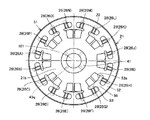
図2は、図1中の矢印IIに示す方向から見たモータジェネレータを示す端面図である。図3は、図2中の2点鎖線IIIで囲まれた範囲を拡大して示す断面図である。 FIG. 2 is an end view showing the motor generator as seen from the direction indicated by arrow II in FIG. 3 is an enlarged cross-sectional view of a range surrounded by a two-dot chain line III in FIG.
図1から図3を参照して、ロータコア21には、複数の貫通孔27が形成されている。貫通孔27は、中心軸101の軸方向に延び、ロータコア21を貫通するように形成されている。貫通孔27は、ロータコア21の端面21aおよび端面21bに開口するように形成されている。複数の貫通孔27は、中心軸101を中心にその周方向に互いに間隔を隔てて形成されている。
1 to 3, a plurality of through
中心軸101の軸方向から見て、貫通孔27は、幅広部27jおよび幅狭部27kから構成されている(図3中を参照)。幅広部27jは、中心軸101を中心とする周方向において相対的に大きい幅を有し、幅狭部27kは、中心軸101を中心とする周方向において相対的に小さい幅を有する。幅狭部27kは、中心軸101を中心とする半径方向において、ステータコア31と対向する位置に配置されている。幅広部27jは、幅狭部27kよりも内周側に配置されている。
When viewed from the axial direction of the
各貫通孔27には、永久磁石26が挿入されている。永久磁石26と貫通孔27の内壁との間には、微小な隙間が形成されている。永久磁石26は、幅狭部27kに配置されている。
A
本実施の形態では、永久磁石26A,26B,26C,26D,26E,26F,26G,26H,26I,26J,26K,26L,26M,26N,26O,26Pが、挙げた順に周方向に並んで設けられている。なお、図2中に示す永久磁石26の数は、一例であり、モータジェネレータ10に要求される性能等によって適宜選択される。
In the present embodiment, the
樹脂モールド部51は、ロータコア21の端面21aおよび端面21bをそれぞれ部分的に覆うとともに、その端面21aと端面21bとの間を挟持するように設けられている。さらに、樹脂モールド部51は、永久磁石26と貫通孔27の内壁との間の隙間を充填するように設けられている。
The
樹脂モールド部51の形状についてより具体的に説明すると、樹脂モールド部51は、外周部52と、凸部としての内周部53と、隙間充填部54と、被覆部55と、中間部56とを含んで構成されている。
The shape of the
外周部52、内周部53および中間部56は、ロータコア21の端面21aおよび端面21b上に設けられている。外周部52、内周部53および中間部56は、端面21aおよび端面21bから、中心軸101の軸方向に突出するように設けられている。
The outer
外周部52は、中心軸101を中心とする周方向に沿って連続的に延在するように設けられている。外周部52は、中心軸101を中心に環状に延在するように設けられている。外周部52は、端面21aおよび端面21bに露出する永久磁石26の外周側の端部を覆うように設けられている。
The outer
内周部53は、中心軸101を中心とする周方向に沿って断続的に延在するように設けられている。内周部53は、外周部52よりも内周側に配置されている。内周部53は、端面21aおよび端面21bに露出する永久磁石26の内周側の端部を覆うように設けられている。内周部53は、隣接する永久磁石26の組(永久磁石26A,26Bの組、永久磁石26C,26Dの組、永久磁石26E,26Fの組、永久磁石26G,26Hの組、永久磁石26I,26Jの組、永久磁石26K,26Lの組、永久磁石26M,26Nの組、永久磁石26O,26Pの組)をそれぞれ一括に覆うように設けられている。
The inner
中間部56は、内周部53と外周部52との間を接続するように設けられている。中間部56は、内周部53から、その内周部53によって一括に覆われた永久磁石26の間(たとえば、永久磁石26Aと永久磁石26Bとの間)を通り、外周部52に達するように設けられている。中間部56は、中心軸101を中心とする半径方向に延びて形成されている。
The
隙間充填部54および被覆部55は、貫通孔27の内部に配置されている。隙間充填部54は、貫通孔27の内壁と磁石26との間の隙間を充填するように設けられている。被覆部55は、永久磁石26の内周側を覆うように設けられている。端面21a上に配置された外周部52および内周部53と、端面21b上に配置された外周部52および内周部53とは、隙間充填部54および被覆部55によって互いに繋がって形成されている。
The
このような構成を備える樹脂モールド部51によって、永久磁石26は、貫通孔27の内部に固定されている。また、樹脂モールド部51によって、端面21aおよび端面21bに対して中心軸101の軸方向に沿った圧縮力が作用し、複数枚の電磁鋼板22からなるロータコア21が一体に保持されている。
The
本実施の形態におけるモータジェネレータ10の冷却構造においては、貫通孔27の内部にオイル通路28が形成されている。オイル通路28は、中心軸101の軸方向に沿って延び、ロータコア21を貫通するように形成されている。オイル通路28は、端面21aおよび端面21bに開口するように形成されている。オイル通路28は、貫通孔27の幅広部27jに形成されている。
In the cooling structure of
オイル通路28の外周側には、被覆部55が配置されている。言い換えれば、オイル通路28の外周側の内壁は、被覆部55の表面55aによって形成されている。被覆部55は、端面21aと端面21bとの間のオイル通路28の全長に渡って設けられている。オイル通路28と永久磁石26とは、被覆部55を挟んだその両側に形成されている。被覆部55は、中心軸101を中心とする内周側においてオイル通路28の空間を規定するとともに、中心軸101を中心とする外周側において永久磁石26を固定する役割を果たしている。
A covering
図4は、図1中のモータジェネレータの冷却構造を示す断面図である。図2から図4を参照して、複数のオイル供給孔43が、中心軸101を中心とする周方向に互いに間隔を隔てて形成されている。
FIG. 4 is a sectional view showing a cooling structure of the motor generator in FIG. With reference to FIGS. 2 to 4, a plurality of oil supply holes 43 are formed at intervals in the circumferential direction around the
オイル供給孔43は、中心軸101を中心とする半径方向に延び、中空部42とその外部空間との間を貫通させるように形成されている。オイル供給孔43は、中心軸101の軸方向において、端面21aの直上で開口するように形成されている。オイル供給孔43は、中心軸101の軸周りにおいて、隣接する永久磁石26の各組(永久磁石26A,26Bの組、永久磁石26C,26Dの組、永久磁石26E,26Fの組、永久磁石26G,26Hの組、永久磁石26I,26Jの組、永久磁石26K,26Lの組、永久磁石26M,26Nの組、永久磁石26O,26Pの組)に対応して形成されている。オイル供給孔43は、隣接する永久磁石26の中心位相位置(たとえば、永久磁石26Aと永久磁石26Bとの間の中心となる位相位置)に形成されている。
The
内周部53は、端面21aおよび端面21b上において、オイル通路28の開口面の外周側の縁に沿って設けられている。内周部53は、端面21aおよび端面21b上で、中心軸101を中心とする半径方向においてオイル供給孔43と対向する表面53aを有する。表面53aは、被覆部55の表面55aから連続して形成されている。
The inner
被覆部55は、その厚みが、端面21b側よりも端面21a側で大きくなるように形成されている(T2<T1)。被覆部55は、中心軸101と表面55aとの間の距離が、端面21a側で相対的に小さくなり、端面21b側で相対的に大きくなるように形成されている。被覆部55は、表面55aが端面21a側から端面21b側に向かうほど拡径するように、中心軸101に対して傾斜して形成されている。
The covering
このように構成されたモータジェネレータ10の冷却構造においては、オイルポンプ48によって中空部42に導入されたオイルが、オイル供給孔43を通じて端面21a上に供給される。端面21a上に供給されたオイルは、ロータコア21の回転に伴って生じる遠心力によって外周側に飛散する。オイルは、内周部53の表面53aに衝突することによって、端面21a上からオイル通路28の内部に導かれる。オイルは、被覆部55の表面55aに沿いながら端面21a側から端面21b側に向けて流れ、この間、ロータコア21を冷却する。
In the cooling structure of the
この際、オイル通路28の外周側が被覆部55によって覆われているため、遠心力を受けたオイルが電磁鋼板22間の隙間を通って、ロータコア21とステータコア31との間に侵入することを防止できる。
At this time, since the outer peripheral side of the
また、被覆部55の表面55aが端面21a側から端面21b側に向けて傾斜するため、オイル通路28においてオイルを円滑に流通させることができる。また、オイル通路28と永久磁石26との間が被覆部55のみによって隔てられているため、ロータコア21の回転時に最も発熱が大きくなる永久磁石26を効率よく冷却することができる。
Further, since the
オイル通路28を流通したオイルは、端面21b上に排出され、さらに遠心力によって外周側に飛散する。これにより、オイルは、飛散した先に配置されるコイルエンド部36qを冷却する。
The oil that has flowed through the
以上に説明した、この発明の実施の形態1におけるモータジェネレータ10の冷却構造は、積層鋼板としての複数枚の電磁鋼板22からなるロータコア21と、ロータコア21を樹脂モールドする樹脂モールド部51とを備える。ロータコア21には、回転軸方向(中心軸101の軸方向)に貫通する貫通孔27が形成されている。ロータコア21は、貫通孔27の内部に冷媒としてのオイルが流通する冷媒通路としてのオイル通路28を形成する。樹脂モールド部51は、オイル通路28の外周側を被覆する被覆部55を有する。
The cooling structure for
このように構成された、この発明の実施の形態1におけるモータジェネレータ10の冷却構造によれば、オイル通路28の外周側に配置される被覆部55によって、オイル通路28を流通するオイルがロータコア21とステータコア31との間に侵入することを防止できる。これにより、ロータコア21およびステータコア31間でオイルの引き摺り抵抗が生じることを防止できる。
According to the cooling structure for
また、本実施の形態では、複数枚の電磁鋼板22からなるロータコア21を一体化するとともに、ロータコア21に対して永久磁石26を固定するための樹脂モールド部51に、被覆部55が設けられる。このため、ロータコア21の樹脂モールド工程時に一括に被覆部55を設けることができ、低コストで上記冷却構造を製造することができる。
In the present embodiment, the
なお、本実施の形態では、本発明における回転電機の冷却構造をハイブリッド自動車に搭載されるモータジェネレータに適用した場合を説明したが、これに限られず、電気自動車に搭載されるモータや、一般的な産業用モータに適用してもよい。 In the present embodiment, the case where the cooling structure for a rotating electrical machine according to the present invention is applied to a motor generator mounted on a hybrid vehicle has been described. However, the present invention is not limited to this, and a motor mounted on an electric vehicle, The present invention may be applied to various industrial motors.
(実施の形態2)
図5は、この発明の実施の形態2におけるモータジェネレータの冷却構造を示す端面図である。図6は、図5中のモータジェネレータの冷却構造を示す別の端面図である。図7は、図5中のモータジェネレータの冷却構造を示す断面図である。(Embodiment 2)
FIG. 5 is an end view showing the cooling structure for the motor generator in the second embodiment of the present invention. FIG. 6 is another end view showing a cooling structure of the motor generator in FIG. FIG. 7 is a sectional view showing a cooling structure of the motor generator in FIG.
図7中の矢印Vに示す方向から見たモータジェネレータが図5中に示され、図7中の矢印VIに示す方向から見たモータジェネレータが図6中に示されている。図5中のIV−IV線上に沿ったモータジェネレータが図4中に示され、図5中のVII−VII線上に沿ったモータジェネレータが図7中に示されている。 The motor generator viewed from the direction indicated by the arrow V in FIG. 7 is shown in FIG. 5, and the motor generator viewed from the direction indicated by the arrow VI in FIG. 7 is shown in FIG. A motor generator along line IV-IV in FIG. 5 is shown in FIG. 4, and a motor generator along line VII-VII in FIG. 5 is shown in FIG.
本実施の形態におけるモータジェネレータの冷却構造は、実施の形態1におけるモータジェネレータ10の冷却構造と比較して、基本的に同様の構造を備える。以下、重複する構造についてはその説明を繰り返さない。
The motor generator cooling structure in the present embodiment is basically the same as that of
図4から図7を参照して、本実施の形態では、ロータシャフト41に、実施の形態1におけるオイル供給孔43に替えてオイル供給孔43pおよびオイル供給孔43qが形成されている。より具体的には、複数のオイル供給孔43pが、中心軸101の軸方向において、端面21aの直上に開口するように形成され、複数のオイル供給孔43qが、中心軸101の軸方向において、端面21bの直上に開口するように形成されている。
4 to 7, in the present embodiment,
オイル供給孔43pとオイル供給孔43qとは、中心軸101を中心とする周方向において互いにずれた位置に形成されている。オイル供給孔43pは、永久磁石26A,26Bの組、永久磁石26E,26Fの組、永久磁石26I,26Jの組、永久磁石26M,26Nの組に対応して形成されている。オイル供給孔43qは、永久磁石26C,26Dの組、永久磁石26G,26Hの組、永久磁石26K,26Lの組、永久磁石26O,26Pの組に対応して形成されている。
The
オイル供給孔43pから供給されたオイルが流通する貫通孔27、すなわち、永久磁石26A,26Bの組、永久磁石26E,26Fの組、永久磁石26I,26Jの組、永久磁石26M,26Nの組に対応する貫通孔27には、図4中に示すように、厚みが端面21q側よりも端面21p側で大きくなるように被覆部55が設けられている(T2<T1)。オイル供給孔43qから供給されたオイルが流通する貫通孔27、すなわち、永久磁石26C,26Dの組、永久磁石26G,26Hの組、永久磁石26K,26Lの組、永久磁石26O,26Pの組に対応する貫通孔27には、図7中に示すように、厚みが端面21p側よりも端面21q側で大きくなるように被覆部55が設けられる(T2>T1)。
The through
このように構成されたモータジェネレータの冷却構造においては、中空部42に導入されたオイルが、オイル供給孔43pおよびオイル供給孔43qを通じてそれぞれ端面21aおよび端面21b上に供給される。図4中に示すように、端面21a上に供給され、オイル通路28に導かれたオイルは、被覆部55の表面55aに沿いながら端面21a側から端面21b側に向けて流れる。この際、被覆部55がT2<T1の関係を満たすため、オイル通路28においてオイルを円滑に流通させることができる。オイル通路28を流通したオイルは、端面21b上に排出され、さらに遠心力によって外周側に飛散する。これにより、オイルは、飛散した先に配置されるコイルエンド部36qを冷却する。
In the motor generator cooling structure configured as described above, the oil introduced into the
一方、図7中に示すように、端面21b上に供給され、オイル通路28に導かれたオイルは、被覆部55の表面55aに沿いながら端面21b側から端面21a側に向けて流れる。この際、被覆部55がT2>T1の関係を満たすため、オイル通路28においてオイルを円滑に流通させることができる。オイル通路28を流通したオイルは、端面21a上に排出され、さらに遠心力によって外周側に飛散する。これにより、オイルは、飛散した先に配置されるコイルエンド部36pを冷却する。
On the other hand, as shown in FIG. 7, the oil supplied onto the
このように構成された、この発明の実施の形態2におけるモータジェネレータの冷却構造によれば、実施の形態1に記載の効果を同様に得ることができる。さらに、本実施の形態では、ロータシャフト41にオイル供給孔43p,43qを形成するとともに、オイルの流れ方向に対応させて被覆部55の傾斜構造を設けることによって、コイルエンド部43pおよびコイルエンド部43qの双方を効率的かつ均等に冷却することが可能となる。
According to the motor generator cooling structure in the second embodiment of the present invention configured as described above, the effects described in the first embodiment can be obtained in the same manner. Further, in the present embodiment, the
(実施の形態3)
図8は、この発明の実施の形態3におけるモータジェネレータの冷却構造を示す端面図である。図8中には、図1中のロータコア21の端面21b側から見たモータジェネレータの冷却構造が示されている。図9は、図8中のIX−IX線上に沿ったモータジェネレータの冷却構造を示す断面図である。(Embodiment 3)
FIG. 8 is an end view showing the cooling structure for the motor generator in the third embodiment of the present invention. FIG. 8 shows a motor generator cooling structure viewed from the
本実施の形態におけるモータジェネレータの冷却構造は、実施の形態1におけるモータジェネレータ10の冷却構造と比較して、基本的には同様の構造を備える。以下、重複する構造についてはその説明を繰り返さない。
The motor generator cooling structure in the present embodiment is basically similar to that of
図8および図9を参照して、本実施の形態では、端面21b上に配置される樹脂モールド部51にガイド部61が形成されている。ガイド部61は、端面21bにおけるオイル通路28の開口面から外周側に延びる溝形状に形成されている。ガイド部61は、内周部53、中間部56および外周部52を順に通り、中心軸101を中心とする半径方向に延びる溝形状に形成されている。
With reference to FIGS. 8 and 9, in the present embodiment,
このように構成されたモータジェネレータの冷却構造においては、オイル通路28を流れ、端面21b上に排出されたオイルが、溝形状を有するガイド部61によってコイルエンド部36qに向けて案内される。これにより、コイルエンド部36qにより多くのオイルを供給することが可能となる。
In the motor generator cooling structure configured as described above, the oil flowing through the
このように構成された、この発明の実施の形態3におけるモータジェネレータの冷却構造によれば、実施の形態1に記載の効果を同様に得ることができる。さらに、樹脂モールド部51にガイド部61を形成することによって、コイルエンド部36qをさらに効率的に冷却することができる。
According to the motor generator cooling structure in the third embodiment of the present invention configured as described above, the effects described in the first embodiment can be obtained in the same manner. Furthermore, by forming the
なお、以上に説明した実施の形態1〜3に記載のモータジェネレータの冷却構造を適宜組み合わせて、新たなモータジェネレータの冷却構造を構成してもよい。 Note that a new motor generator cooling structure may be configured by appropriately combining the motor generator cooling structures described in the first to third embodiments.
今回開示された実施の形態はすべての点で例示であって制限的なものではないと考えられるべきである。本発明の範囲は上記した説明ではなくて請求の範囲によって示され、請求の範囲と均等の意味および範囲内でのすべての変更が含まれることが意図される。 The embodiment disclosed this time should be considered as illustrative in all points and not restrictive. The scope of the present invention is defined by the terms of the claims, rather than the description above, and is intended to include any modifications within the scope and meaning equivalent to the terms of the claims.
この発明は、主に、動力源としてモータを備える車両に適用される。 The present invention is mainly applied to a vehicle including a motor as a power source.
10 モータジェネレータ、12 端子台、13 インバータ、14 バッテリ、15 減速機構、16 ディファレンシャル機構、17 ドライブシャフト受け部、21 ロータコア、21a,21b 端面、22 電磁鋼板、26,26A〜26P 永久磁石、27 貫通孔、27j 幅広部、27k 幅狭部、28 オイル通路、31 ステータコア、31a,31b 端面、32 電磁鋼板、36 コイル、36p,36q コイルエンド部、41 ロータシャフト、42 中空部、43,43p,43q オイル供給孔、46,47 ベアリング、48 オイルポンプ、51 樹脂モールド部、52 外周部、53 内周部、53a,55a 表面、54 隙間充填部、55 被覆部、56 中間部、61 ガイド部、101 中心軸。
DESCRIPTION OF
Claims (9)
前記ロータコア(21)を樹脂モールドする樹脂モールド部(51)とを備え、
前記樹脂モールド部(51)は、前記冷媒通路(28)の外周側を被覆する被覆部(55)を有し、
前記冷媒通路(28)の外周側の内壁は、前記被覆部(55)の表面(55a)によって形成される、回転電機の冷却構造。A through-hole (27) penetrating in the direction of the rotation axis is formed, a refrigerant passage (28) through which a refrigerant flows is formed inside the through-hole (27), and a rotor core (21) made of a laminated steel plate (22);
A resin mold part (51) for resin-molding the rotor core (21),
The resin mold part (51) has a covering part (55) covering the outer peripheral side of the refrigerant passage (28),
A cooling structure for a rotating electrical machine, wherein an inner wall on the outer peripheral side of the refrigerant passage (28) is formed by a surface (55a) of the covering portion (55).
前記第1端面(21a)上に冷媒を供給する冷媒供給部(43)を備え、
前記被覆部(55)は、その厚みが、前記第2端面(21b)側よりも前記第1端面(21a)側で大きくなるように設けられる、請求の範囲1に記載の回転電機の冷却構造。The rotor core (21) has a first end surface (21a) and a second end surface (21b) facing the one end side and the other end side, respectively, in the direction of the rotation axis, and opening the refrigerant passage (28). ,
A refrigerant supply section (43) for supplying a refrigerant on the first end face (21a);
The cooling structure for a rotating electrical machine according to claim 1, wherein the covering portion (55) is provided such that the thickness thereof is larger on the first end surface (21a) side than on the second end surface (21b) side. .
前記端面(21a)上に冷媒を供給する冷媒供給部(43)を備え、
前記樹脂モールド部(51)は、前記冷媒通路(28)の開口面の外周側の縁に沿うように前記端面(21a)上に設けられ、前記ロータコア(21)の回転軸方向に突出する凸部(53)をさらに有する、請求の範囲1に記載の回転電機の冷却構造。The rotor core (21) has an end surface (21a) facing in the rotation axis direction and opening the refrigerant passage (28), and
A refrigerant supply part (43) for supplying a refrigerant on the end face (21a);
The resin mold part (51) is provided on the end surface (21a) so as to extend along the outer peripheral edge of the opening surface of the refrigerant passage (28), and protrudes in the rotation axis direction of the rotor core (21). The cooling structure for a rotating electric machine according to claim 1, further comprising a portion (53).
複数の前記貫通孔(27)が、前記ロータコア(21)の回転軸を中心とする周方向において互いに間隔を隔てて形成され、さらに、
前記第1端面(21a)上に冷媒を供給する第1冷媒供給部(43p)と、
前記第2端面(21b)上に冷媒を供給する第2冷媒供給部(43q)とを備え、
前記第1冷媒供給部(43p)と前記第2冷媒供給部(43q)とは、前記ロータコア(21)の回転軸を中心とする周方向において互いにずれた位置に設けられる、請求の範囲1に記載の回転電機の冷却構造。The rotor core (21) has a first end surface (21a) and a second end surface (21b) facing the one end side and the other end side in the direction of the rotation axis, respectively, and opening the refrigerant passage (28),
A plurality of the through holes (27) are formed spaced apart from each other in a circumferential direction around the rotation axis of the rotor core (21),
A first refrigerant supply section (43p) for supplying a refrigerant on the first end face (21a);
A second refrigerant supply part (43q) for supplying a refrigerant on the second end face (21b),
The range according to claim 1, wherein the first refrigerant supply part (43p) and the second refrigerant supply part (43q) are provided at positions shifted from each other in a circumferential direction around the rotation axis of the rotor core (21). The rotating electrical machine cooling structure described.
前記樹脂モールド部(51)は、前記磁石(26)と前記貫通孔(27)の内壁との間を充填するように設けられ、
前記貫通孔(27)内において、前記磁石(26)と前記冷媒通路(28)とが、前記被覆部(55)を挟んだ両側に配置される、請求の範囲1に記載の回転電機の冷却構造。A magnet (26) inserted into the through hole (27);
The resin mold part (51) is provided so as to fill a space between the magnet (26) and the inner wall of the through hole (27),
The cooling of the rotating electrical machine according to claim 1, wherein the magnet (26) and the refrigerant passage (28) are arranged on both sides of the covering portion (55) in the through hole (27). Construction.
前記樹脂モールド部(51)は、前記第1端面(21a)および前記第2端面(21b)を覆うとともに、前記第1端面(21a)と前記第2端面(21b)との間で繋がって設けられ、積層鋼板(22)からなる前記ロータコア(21)を一体に保持する、請求の範囲1に記載の回転電機の冷却構造。The rotor core (21) has a first end surface (21a) and a second end surface (21b) facing the one end side and the other end side in the rotation axis direction,
The resin mold part (51) covers the first end surface (21a) and the second end surface (21b), and is connected between the first end surface (21a) and the second end surface (21b). The rotating electrical machine cooling structure according to claim 1, wherein the rotor core (21) made of a laminated steel plate (22) is integrally held.
前記端面(31a)上に位置決めされるコイルエンド部(36q)を有し、前記ステータコア(31)に巻回されるコイル(36)とをさらに備える、請求の範囲1に記載の回転電機の冷却構造。A stator core (31) having an end face (31a) facing the rotation axis direction of the rotor core (21) and disposed on an outer periphery of the rotor core (21);
The cooling of a rotating electrical machine according to claim 1, further comprising a coil end portion (36q) positioned on the end face (31a) and a coil (36) wound around the stator core (31). Construction.
前記第1端面(21a)上に冷媒を供給する冷媒供給部(43)を備え、
前記樹脂モールド部(51)は、前記第2端面(21b)上に配置され、前記冷媒通路(28)を通じて排出された冷媒を前記コイルエンド部(36q)に向けて案内するように形成されたガイド部(61)を有する、請求の範囲8に記載の回転電機の冷却構造。The rotor core (21) has a first end surface (21a) and a second end surface (21b) facing the one end side and the other end side, respectively, in the direction of the rotation axis, and opening the refrigerant passage (28). ,
A refrigerant supply section (43) for supplying a refrigerant on the first end face (21a);
The resin mold part (51) is disposed on the second end face (21b) and formed to guide the refrigerant discharged through the refrigerant passage (28) toward the coil end part (36q). The cooling structure for a rotating electric machine according to claim 8, comprising a guide portion (61).
Applications Claiming Priority (1)
| Application Number | Priority Date | Filing Date | Title |
|---|---|---|---|
| PCT/JP2009/067877 WO2011045860A1 (en) | 2009-10-16 | 2009-10-16 | Cooling structure for dynamo-electric machine |
Publications (2)
| Publication Number | Publication Date |
|---|---|
| JPWO2011045860A1 JPWO2011045860A1 (en) | 2013-03-04 |
| JP5333606B2 true JP5333606B2 (en) | 2013-11-06 |
Family
ID=43875918
Family Applications (1)
| Application Number | Title | Priority Date | Filing Date |
|---|---|---|---|
| JP2011543909A Expired - Fee Related JP5333606B2 (en) | 2009-10-16 | 2009-10-16 | Cooling structure of rotating electric machine |
Country Status (4)
| Country | Link |
|---|---|
| US (1) | US9030062B2 (en) |
| EP (1) | EP2490322A4 (en) |
| JP (1) | JP5333606B2 (en) |
| WO (1) | WO2011045860A1 (en) |
Families Citing this family (15)
| Publication number | Priority date | Publication date | Assignee | Title |
|---|---|---|---|---|
| JP5638622B2 (en) * | 2010-11-12 | 2014-12-10 | 川崎重工業株式会社 | Electric motorcycle and cooling structure for electric vehicle |
| JP2013021811A (en) * | 2011-07-11 | 2013-01-31 | Toyota Motor Corp | Rotor of rotary electric machine |
| JP2013126311A (en) * | 2011-12-15 | 2013-06-24 | Toyota Motor Corp | Rotary electric machine |
| JP2013183480A (en) * | 2012-02-29 | 2013-09-12 | Toyota Motor Corp | Cooling structure of rotor for rotary electric machine and rotary electric machine |
| JP2015006088A (en) * | 2013-06-21 | 2015-01-08 | トヨタ紡織株式会社 | Core of rotary electric machine and method of manufacturing the same |
| JP6548276B2 (en) * | 2017-10-04 | 2019-07-24 | 本田技研工業株式会社 | Rotor of electric rotating machine |
| US10855151B2 (en) * | 2017-12-20 | 2020-12-01 | Abb Schweiz Ag | Rotor balancing/fixation via injection or compression molding |
| KR102122238B1 (en) * | 2019-01-07 | 2020-06-26 | 엘지전자 주식회사 | Electric motor |
| JP6870009B2 (en) * | 2019-01-17 | 2021-05-12 | 本田技研工業株式会社 | Rotating machine |
| US11545860B2 (en) | 2021-02-22 | 2023-01-03 | GM Global Technology Operations LLC | Inserts for motor rotor core |
| US11770039B2 (en) * | 2021-03-15 | 2023-09-26 | GM Global Technology Operations LLC | Rotor cooling with heat conductive material |
| US11646620B2 (en) | 2021-04-14 | 2023-05-09 | GM Global Technology Operations LLC | Preloading magnets in a rotor core |
| US11777348B2 (en) | 2021-08-03 | 2023-10-03 | GM Global Technology Operations LLC | Rotor core with load bearing polymer and insert |
| DE102022131184A1 (en) * | 2022-11-25 | 2024-05-29 | Schaeffler Technologies AG & Co. KG | Rotor and electric machine |
| DE102023117609A1 (en) | 2023-07-04 | 2025-01-09 | Dr. Ing. H.C. F. Porsche Aktiengesellschaft | rotor of a separately excited synchronous machine |
Citations (8)
| Publication number | Priority date | Publication date | Assignee | Title |
|---|---|---|---|---|
| JPS6455039A (en) * | 1987-08-22 | 1989-03-02 | Fanuc Ltd | Liquid-proof rotor |
| JPH09182375A (en) * | 1995-12-25 | 1997-07-11 | Aisin Aw Co Ltd | Cooling circuit of motor |
| JP2003219607A (en) * | 2002-01-17 | 2003-07-31 | General Motors Corp <Gm> | Liquid cooling system for electric motor using centrifugal force |
| JP2004222347A (en) * | 2003-01-09 | 2004-08-05 | Toyota Motor Corp | Motor rotor |
| JP2006006091A (en) * | 2004-06-21 | 2006-01-05 | Nissan Motor Co Ltd | Cooling device for motor |
| JP2006067777A (en) * | 2004-07-30 | 2006-03-09 | Honda Motor Co Ltd | Cooling structure for rotary electric machine |
| WO2007026900A1 (en) * | 2005-09-01 | 2007-03-08 | Toyota Jidosha Kabushiki Kaisha | Production method of rotor and rotor |
| JP2008178243A (en) * | 2007-01-19 | 2008-07-31 | Toyota Motor Corp | Magnet temperature estimation device, magnet protection device, magnet temperature estimation method, and magnet protection method |
Family Cites Families (11)
| Publication number | Priority date | Publication date | Assignee | Title |
|---|---|---|---|---|
| JPS58139865U (en) * | 1982-03-17 | 1983-09-20 | 株式会社明電舎 | Oil-sealed rotating electric machine |
| JPS61121728A (en) * | 1984-11-14 | 1986-06-09 | Fanuc Ltd | Liquid cooled motor |
| JPH0648355U (en) | 1992-12-07 | 1994-06-28 | 東洋電機製造株式会社 | Rotating machine rotor |
| JP3777880B2 (en) | 1999-06-29 | 2006-05-24 | 神鋼電機株式会社 | Electric motor rotor and electric motor cooling method |
| US6069421A (en) * | 1999-08-30 | 2000-05-30 | Electric Boat Corporation | Electric motor having composite encapsulated stator and rotor |
| JP4715028B2 (en) | 2001-05-14 | 2011-07-06 | 日産自動車株式会社 | Rotating electric machine |
| JP3979389B2 (en) | 2004-01-09 | 2007-09-19 | 日産自動車株式会社 | Motor rotor cooling structure |
| JP4232830B2 (en) * | 2007-02-15 | 2009-03-04 | ダイキン工業株式会社 | Motor rotor and compressor provided with the same |
| JP2009071923A (en) | 2007-09-11 | 2009-04-02 | Komatsu Ltd | Cooling structure of electric motor |
| JP2009171785A (en) * | 2008-01-18 | 2009-07-30 | Toyota Motor Corp | Rotating electric machine |
| JP5168472B2 (en) * | 2008-02-18 | 2013-03-21 | 株式会社豊田自動織機 | Rotating electric machine |
-
2009
- 2009-10-16 US US13/502,059 patent/US9030062B2/en not_active Expired - Fee Related
- 2009-10-16 JP JP2011543909A patent/JP5333606B2/en not_active Expired - Fee Related
- 2009-10-16 EP EP09850402.0A patent/EP2490322A4/en not_active Withdrawn
- 2009-10-16 WO PCT/JP2009/067877 patent/WO2011045860A1/en active Application Filing
Patent Citations (8)
| Publication number | Priority date | Publication date | Assignee | Title |
|---|---|---|---|---|
| JPS6455039A (en) * | 1987-08-22 | 1989-03-02 | Fanuc Ltd | Liquid-proof rotor |
| JPH09182375A (en) * | 1995-12-25 | 1997-07-11 | Aisin Aw Co Ltd | Cooling circuit of motor |
| JP2003219607A (en) * | 2002-01-17 | 2003-07-31 | General Motors Corp <Gm> | Liquid cooling system for electric motor using centrifugal force |
| JP2004222347A (en) * | 2003-01-09 | 2004-08-05 | Toyota Motor Corp | Motor rotor |
| JP2006006091A (en) * | 2004-06-21 | 2006-01-05 | Nissan Motor Co Ltd | Cooling device for motor |
| JP2006067777A (en) * | 2004-07-30 | 2006-03-09 | Honda Motor Co Ltd | Cooling structure for rotary electric machine |
| WO2007026900A1 (en) * | 2005-09-01 | 2007-03-08 | Toyota Jidosha Kabushiki Kaisha | Production method of rotor and rotor |
| JP2008178243A (en) * | 2007-01-19 | 2008-07-31 | Toyota Motor Corp | Magnet temperature estimation device, magnet protection device, magnet temperature estimation method, and magnet protection method |
Also Published As
| Publication number | Publication date |
|---|---|
| US20120200179A1 (en) | 2012-08-09 |
| US9030062B2 (en) | 2015-05-12 |
| JPWO2011045860A1 (en) | 2013-03-04 |
| WO2011045860A1 (en) | 2011-04-21 |
| EP2490322A1 (en) | 2012-08-22 |
| EP2490322A4 (en) | 2017-12-13 |
Similar Documents
| Publication | Publication Date | Title |
|---|---|---|
| JP5333606B2 (en) | Cooling structure of rotating electric machine | |
| JP4492745B2 (en) | Rotating electric machine | |
| CN103620918B (en) | The cooling structure of electric rotating machine | |
| JP4949983B2 (en) | Rotating electric machine | |
| JP4560067B2 (en) | Rotating electric machine | |
| JP4389918B2 (en) | Rotating electric machine and AC generator | |
| JP2012223075A (en) | Cooling structure of rotary electric machine | |
| JP2010124659A (en) | Rotating electric machine | |
| WO2008156127A1 (en) | Rotating electric machine cooling structure | |
| JP4867598B2 (en) | Manufacturing method of rotor | |
| JP2010124657A (en) | Rotating electric machine | |
| JP2009118712A (en) | Rotating electric machine | |
| JP5240174B2 (en) | Motor cooling structure | |
| JP2009195082A (en) | Stator cooling structure | |
| JP7584372B2 (en) | Rotating Electric Machine | |
| JP5304617B2 (en) | Motor cooling structure | |
| CN110800193B (en) | Stator of rotating electric machine, rotating electric machine, and manufacturing method of stator of rotating electric machine | |
| JP2010124658A (en) | Rotating electric machine | |
| JP2009027836A (en) | Rotating electric machine | |
| JP2007336677A (en) | Rotating electric machine and vehicle | |
| JP2008312324A (en) | Stator cooling structure | |
| JP6014481B2 (en) | Rotor for rotating electrical machine for vehicles | |
| JP2011142787A (en) | Cooling structure for electric motor | |
| JPWO2012101813A1 (en) | Motor cooling device | |
| JP2010273504A (en) | Rotor, rotating electrical machine and vehicle |
Legal Events
| Date | Code | Title | Description |
|---|---|---|---|
| TRDD | Decision of grant or rejection written | ||
| A01 | Written decision to grant a patent or to grant a registration (utility model) |
Free format text: JAPANESE INTERMEDIATE CODE: A01 Effective date: 20130702 |
|
| A61 | First payment of annual fees (during grant procedure) |
Free format text: JAPANESE INTERMEDIATE CODE: A61 Effective date: 20130715 |
|
| LAPS | Cancellation because of no payment of annual fees |