JP5313714B2 - Electric power steering device - Google Patents
Electric power steering device Download PDFInfo
- Publication number
- JP5313714B2 JP5313714B2 JP2009025856A JP2009025856A JP5313714B2 JP 5313714 B2 JP5313714 B2 JP 5313714B2 JP 2009025856 A JP2009025856 A JP 2009025856A JP 2009025856 A JP2009025856 A JP 2009025856A JP 5313714 B2 JP5313714 B2 JP 5313714B2
- Authority
- JP
- Japan
- Prior art keywords
- steering
- reaction force
- toe
- yaw rate
- angle
- Prior art date
- Legal status (The legal status is an assumption and is not a legal conclusion. Google has not performed a legal analysis and makes no representation as to the accuracy of the status listed.)
- Expired - Fee Related
Links
Images


Landscapes
- Steering Control In Accordance With Driving Conditions (AREA)
- Control Of Driving Devices And Active Controlling Of Vehicle (AREA)
- Regulating Braking Force (AREA)
- Power Steering Mechanism (AREA)
- Steering-Linkage Mechanisms And Four-Wheel Steering (AREA)
Abstract
Description
本発明は、操舵アシスト用モータによってステアリングホイールに操舵反力を付与し得る電動パワーステアリング装置に係り、リヤトーコントロール装置などの車両挙動制御装置を備えた車両に適用されるものである。 The present invention relates to an electric power steering device that can apply a steering reaction force to a steering wheel by a steering assist motor, and is applied to a vehicle including a vehicle behavior control device such as a rear toe control device.
運転者のステアリング操作負荷を軽減するために、電動モータによりアシストトルクを発生させる電動パワーステアリング装置が広く知られている。このアシストトルクは一般に、運転者による操舵トルクと車速や路面状況などの検出値とに基づいて決定される。 In order to reduce a driver's steering operation load, an electric power steering device that generates an assist torque by an electric motor is widely known. This assist torque is generally determined based on the steering torque by the driver and detected values such as the vehicle speed and road surface condition.
一方、車体のヨーレイトや横加速度などの運動状態量に係る検出値に基づいて操舵反力トルクを設定し、この操舵反力トルクを加えることにより、運動状態量に応じてアシストトルクを調整する技術が知られている(特許文献1参照)。これによれば、横風や轍路走行などの外乱が車両に作用した際の偏向抑制性能が高められ、車両の走行安定性を向上することができ、雪道などのタイヤとの摩擦係数が低い路面(以下、低μ路と称す)や低速走行時にも運転者にかかるステアリング操作負荷が軽減される。 On the other hand, a technique for setting a steering reaction torque based on a detection value related to a motion state quantity such as a yaw rate or a lateral acceleration of a vehicle body, and adjusting the assist torque according to the motion state quantity by adding the steering reaction force torque. Is known (see Patent Document 1). According to this, the deflection suppression performance when disturbances such as crosswinds and rusty roads are applied to the vehicle can be improved, the running stability of the vehicle can be improved, and the friction coefficient with tires such as snowy roads is low. The steering operation load applied to the driver is reduced even on the road surface (hereinafter referred to as a low μ road) or at low speeds.
他方、車両の回頭性や操縦安定性を向上させるために、左右の後輪に対してアクチュエータをそれぞれ設け、アクチュエータを駆動することにより後輪のトー角を可変制御するリヤトーコントロール装置を備えた4輪操舵車両が種々開発されている(例えば、特許文献2参照)。4輪操舵車両では、例えば、前輪舵角に対する後輪舵角(後輪トー角)の比が予め低速時逆相、高速時同相となるように設定したり、各種制御パラメータ(前輪舵角、車速等)に基づいて車体の目標ヨーレイトを設定し、実ヨーレイトを目標ヨーレイトに近づけるように後輪舵角を設定したりすることが一般的に行われる。 On the other hand, in order to improve the turning performance and steering stability of the vehicle, there is provided a rear toe control device that is provided with actuators for the left and right rear wheels and variably controls the toe angle of the rear wheels by driving the actuators. Various wheel steering vehicles have been developed (see, for example, Patent Document 2). In a four-wheel steered vehicle, for example, the ratio of the rear wheel rudder angle (rear wheel toe angle) to the front wheel rudder angle is set in advance to be in reverse phase at low speed and in phase at high speed, and various control parameters (front wheel rudder angle, In general, the target yaw rate of the vehicle body is set based on the vehicle speed and the rear wheel steering angle is set so that the actual yaw rate approaches the target yaw rate.
ところが、後輪転舵状態でリヤトーコントロール装置が故障し、後輪舵角の制御を行えなくなった場合、運転者がステアリングホイールを操舵角0に保持すると、後輪のタイヤ横力が車体にヨーモーメントとして作用し、車両は直進しなくなる。そのため、直進走行を維持するためには、ヨーモーメントを打ち消す方向にステアリングホイールを操作する必要が生じる。一方、特許文献1に記載されたような、運動状態量に応じて操舵反力トルクを設定する電動パワーステアリング装置は、例えば、車体のヨーレイトとステアリングホイールの操舵角とに応じて発生させるステアリングホイールの戻し力(操舵反力)を通常のアシストトルクに加えることで、車両の直進性を向上させている。この操舵反力は、車両が直進状態の場合、ヨーレイトは0であり且つ操舵角も0であるという前提の下、制御則が構築されている。
However, when the rear toe control device fails in the rear wheel steering state and the rear wheel steering angle cannot be controlled, if the driver holds the steering wheel at the
しかしながら、このような制御則に基づく電動パワーステアリング装置が4輪操舵車両に適用されると、リヤトーコントロール装置が操舵状態で制御不能に陥った場合、ステアリングホイールの操舵角を0に保持した状態で走行すると、車体にヨーモーメントが作用することから、電動パワーステアリング装置が操舵角を0に戻すような操舵反力をステアリングホイールに付加するほど車体にヨーモーメントが作用するという反力制御と運転者の操舵意思とが干渉するという問題があった。 However, when an electric power steering device based on such a control law is applied to a four-wheel steering vehicle, when the rear toe control device becomes uncontrollable in a steering state, the steering angle of the steering wheel is maintained at zero. Since the yaw moment acts on the vehicle body when traveling, the reaction force control and the driver that the yaw moment acts on the vehicle body as the steering reaction force is applied to the steering wheel so that the electric power steering device returns the steering angle to 0. There was a problem of interference with the steering intention.
本発明は、このような背景に鑑みなされたもので、リヤトーコントロール装置等のような、車体にヨーモーメントを発生させて車両挙動を制御する車両挙動制御装置が故障した場合に、操舵反力を付与し得る電動パワーステアリング装置の制御を適正に行い、ヨーモーメントの打ち消し易くすることを目的とする。 The present invention has been made in view of such a background. When a vehicle behavior control device that controls a vehicle behavior by generating a yaw moment, such as a rear toe control device, malfunctions, the steering reaction force is reduced. An object is to appropriately control the electric power steering device that can be applied and to easily cancel the yaw moment.
上記課題を解決するために第1の発明は、車体(2)にヨーモーメントを発生させて車両挙動を制御する車両挙動制御装置(11)を備えた車両(1)に搭載され、操舵アシスト用モータ(27)によってステアリングホイール(22)に操舵反力(Tb)を付与し得る電動パワーステアリング装置(21)において、車体(2)のヨーレイト(γ)を検出するヨーレイト検出手段(15)と、操舵反力のうち、ヨーレイトに基づいて、ヨーレイトを低減させる方向のヨーレイト反力成分(Tbγ)を設定するヨーレイト成分設定部(32a)と、少なくともヨーレイト反力成分に基づいて、操舵アシスト用モータを駆動制御するモータ制御手段(35)とを備え、ヨーレイト成分設定部は、車両挙動制御装置が故障した場合、車両挙動制御装置が正常な場合よりもヨーレイト反力成分を大きく設定することを特徴とする。 In order to solve the above-mentioned problem, the first invention is mounted on a vehicle (1) including a vehicle behavior control device (11) for controlling a vehicle behavior by generating a yaw moment in the vehicle body (2), and for steering assist. In the electric power steering device (21) capable of applying the steering reaction force (Tb) to the steering wheel (22) by the motor (27), the yaw rate detecting means (15) for detecting the yaw rate (γ) of the vehicle body (2), Among the steering reaction forces, the yaw rate reaction force component (Tbγ) for setting the yaw rate to be reduced based on the yaw rate is set, and the steering assist motor is set based on at least the yaw rate reaction force component. Motor control means (35) for driving control, and the yaw rate component setting unit is configured to control the vehicle behavior control device when the vehicle behavior control device fails. It is characterized in that the yaw rate reaction force component is set larger than in the case where the position is normal.
この発明によれば、電動パワーステアリング装置は、車両挙動制御装置が故障した場合、車体のヨーレイトを低減させるヨーレイト反力成分を大きく設定して操舵アシスト用モータを駆動制御するため、車両挙動制御装置の故障に起因するヨーモーメントを打ち消す修正操舵を行い易くすることができる。 According to the present invention, when the vehicle behavior control device breaks down, the electric power steering device sets the yaw rate reaction force component that reduces the yaw rate of the vehicle body to be large and controls the driving of the steering assist motor. It is possible to facilitate corrective steering that cancels the yaw moment resulting from the failure.
また、第2の発明は、車体(2)にヨーモーメントを発生させて車両挙動を制御する車両挙動制御装置(11)を備えた車両(1)に搭載され、操舵アシスト用モータ(27)によってステアリングホイール(22)に操舵反力(Tb)を付与し得る電動パワーステアリング装置(21)において、ステアリングホイールの操舵角(θ)を検出する操舵角検出手段(9)と、操舵反力のうち、操舵角に基づいて、操舵角を減少させる方向の操舵角反力成分(Tbθ)を設定する操舵角成分設定部(32b)と、少なくとも操舵角反力成分に基づいて、操舵アシスト用モータを駆動制御するモータ制御手段(35)とを備え、操舵角成分設定部は、車両挙動制御装置が故障した場合、車両挙動制御装置が正常な場合よりも操舵角反力成分を小さく設定することを特徴とする。 The second invention is mounted on a vehicle (1) having a vehicle behavior control device (11) for controlling the vehicle behavior by generating a yaw moment in the vehicle body (2), and is provided by a steering assist motor (27). In the electric power steering device (21) capable of applying the steering reaction force (Tb) to the steering wheel (22), the steering angle detection means (9) for detecting the steering angle (θ) of the steering wheel, and the steering reaction force A steering angle component setting unit (32b) for setting a steering angle reaction force component (Tbθ) in a direction for decreasing the steering angle based on the steering angle, and a steering assist motor based on at least the steering angle reaction force component. Motor control means (35) for driving control, and the steering angle component setting unit has a smaller steering angle reaction force component when the vehicle behavior control device fails than when the vehicle behavior control device is normal. It is characterized by setting.
この発明によれば、電動パワーステアリング装置は、車両挙動制御装置が故障した場合、ステアリングホイールの操舵角を減少させる操舵角反力成分を小さく設定して操舵アシスト用モータを駆動制御するため、車両挙動制御装置の故障に起因するヨーモーメントを打ち消す修正操舵を行い易くすることができる。 According to the present invention, when the vehicle behavior control device breaks down, the electric power steering device sets the steering angle reaction force component that decreases the steering angle of the steering wheel to drive and controls the steering assist motor. It is possible to facilitate corrective steering that cancels the yaw moment caused by the failure of the behavior control device.
また、第3の発明は、第1または第2の発明に係る電動パワーステアリング装置(21)において、車両挙動制御装置は、後輪(5)のトー角(δr)を左右独立に可変制御するリヤトーコントロール装置(11)であることを特徴とする。 According to a third aspect of the invention, in the electric power steering device (21) according to the first or second aspect of the invention, the vehicle behavior control device variably controls the toe angle (δr) of the rear wheel (5) independently on the left and right. It is a rear toe control device (11).
この発明によれば、電動パワーステアリング装置は、リヤトーコントロール装置が故障した場合、車体のヨーレイトを低減させるヨーレイト反力成分を大きく設定して、或いはステアリングホイールの操舵角を減少させる操舵角反力成分を小さく設定して操舵アシスト用モータを駆動制御するため、リヤトーコントロール装置の故障に起因するヨーモーメントを打ち消す修正操舵を行い易くすることができる。 According to this invention, when the rear toe control device breaks down, the electric power steering device sets the yaw rate reaction force component that reduces the yaw rate of the vehicle body to a large value, or the steering angle reaction force component that reduces the steering angle of the steering wheel. Since the steering assist motor is driven and controlled with a small value, correction steering for canceling the yaw moment caused by the failure of the rear toe control device can be facilitated.
また、第4の発明は、第1の発明に係る電動パワーステアリング装置(21)において、車両挙動制御装置は、後輪(5)のトー角(δr)を左右独立に可変制御するリヤトーコントロール装置(11)であり、後輪(5)のトー角(δr)を検出する後輪トー角検出手段(17)をさらに備え、操舵角成分設定部(32a)は、リヤトーコントロール装置の故障時に後輪トー角検出手段によって検出された後輪のトー角が左右対称でない場合にのみ、ヨーレイト反力成分を大きく設定することを特徴とする。なお、左右対称でない場合としては、図6に示すように、(A)左右の後輪5l,5rが同一方向に一方の後輪5lがトーイン側に、他方の後輪5rがトーアウト側に)転舵されている状態、(B)左右の後輪5l,5rがトーインとされているが、その転舵量が異なる場合、(C)左右の後輪5l,5rがトーアウトとされているが、その転舵量が異なる場合、(D)一方の後輪5lが舵角0で他方の後輪5rがトーアウトとされている状態、(E)一方の後輪5lが舵角0で他方の後輪5rがトーインとされている状態が挙げられる。
According to a fourth aspect of the present invention, in the electric power steering device (21) according to the first aspect of the invention, the vehicle behavior control device variably controls the toe angle (δr) of the rear wheel (5) independently on the left and right. (11), and further includes a rear wheel toe angle detecting means (17) for detecting a toe angle (δr) of the rear wheel (5), and the steering angle component setting unit (32a) is provided when the rear toe control device fails. The yaw rate reaction force component is set large only when the toe angle of the rear wheel detected by the wheel toe angle detecting means is not symmetrical. As shown in FIG. 6, (A) the left and right
この発明によれば、リヤトーコントロール装置が故障しても、故障時の後輪のトー角が左右対称である場合、すなわち、後輪のトー角が左右輪ともにトーインまたはトーアウト且つ同一転舵量である場合、またはトーゼロ状態での故障時には、直進走行中にヨーモーメントが車体に作用することは殆どないため、ヨーレイト反力成分を大きくせずに通常時のヨーレイト反力成分を設定することで、電動パワーステアリング装置の適正な制御が可能となる。 According to the present invention, even if the rear toe control device fails, the rear wheel toe angle at the time of the failure is symmetrical, that is, the rear wheel toe angle is toe-in or toe-out for both the left and right wheels and the same turning amount. In some cases, or when there is a failure in the toe zero state, the yaw moment hardly acts on the vehicle body during straight running, so by setting the normal yaw rate reaction force component without increasing the yaw rate reaction force component, Appropriate control of the electric power steering device is possible.
また、第5の発明は、第2の発明に係る電動パワーステアリング装置(21)において、車両挙動制御装置は、後輪(5)のトー角(δr)を左右独立に可変制御するリヤトーコントロール装置(11)であり、後輪(5)のトー角(δr)を検出する後輪トー角検出手段(17)をさらに備え、操舵角成分設定部(32a)は、リヤトーコントロール装置の故障時に前記後輪トー角検出手段によって検出された後輪のトー角が左右対称でない場合にのみ、前記操舵角反力成分を小さく設定することを特徴とする。なお、左右対称でない場合としては、第4の発明と同様に、図6に示す(A)〜(E)の状態が挙げられる。 Further, according to a fifth aspect of the present invention, in the electric power steering device (21) according to the second aspect of the invention, the vehicle behavior control device is a rear toe control device that variably controls the toe angle (δr) of the rear wheel (5) independently on the left and right. (11), further comprising rear wheel toe angle detecting means (17) for detecting a toe angle (δr) of the rear wheel (5), wherein the steering angle component setting unit (32a) The steering angle reaction force component is set small only when the rear wheel toe angle detected by the rear wheel toe angle detecting means is not bilaterally symmetric. In addition, as a case where it is not left-right symmetric, the state of (A)-(E) shown in FIG. 6 is mentioned similarly to 4th invention.
この発明によれば、リヤトーコントロール装置が故障しても、故障時の後輪のトー角が左右対称である場合には、車両を直進走行させるためにはステアリングホイールを略中立位置に保持すればよいため、操舵角反力成分を小さくせずに通常時の操舵角反力成分を設定することで、電動パワーステアリング装置の適正な制御が可能となる。 According to the present invention, even if the rear toe control device fails, if the toe angle of the rear wheel at the time of the failure is symmetrical, if the steering wheel is held in a substantially neutral position in order to travel straight ahead, Therefore, by setting the normal steering angle reaction force component without reducing the steering angle reaction force component, it is possible to appropriately control the electric power steering apparatus.
また、第6の発明は、第1または第2の発明に係る電動パワーステアリング装置(21)において、車両挙動制御装置は、前輪とステアリングホイールとが機械的に連結され、当該ステアリングホイールの操舵量に対する前記前輪の舵角比を可変制御するアクティブ・フロント・ステアリング装置であることを特徴とする。 According to a sixth aspect of the present invention, in the electric power steering device (21) according to the first or second aspect of the invention, the vehicle behavior control device is such that the front wheel and the steering wheel are mechanically connected, and the steering amount of the steering wheel is It is an active front steering device that variably controls the steering angle ratio of the front wheels to the front wheel.
この発明によれば、電動パワーステアリング装置は、アクティブ・フロント・ステアリング装置が故障した場合、車体のヨーレイトを低減させるヨーレイト反力成分を大きく設定して、或いはステアリングホイールの操舵角を減少させる操舵角反力成分を小さく設定して操舵アシスト用モータを駆動制御するため、アクティブ・フロント・ステアリング装置の故障に起因するヨーモーメントを打ち消す修正操舵を行い易くすることができる。 According to the present invention, when the active front steering device fails, the electric power steering device sets the yaw rate reaction force component that reduces the yaw rate of the vehicle body to a large value, or reduces the steering angle of the steering wheel. Since the steering assist motor is driven and controlled by setting the reaction force component small, it is possible to facilitate corrective steering that cancels the yaw moment caused by the failure of the active front steering device.
また、第7の発明は、第1または第2の発明に係る電動パワーステアリング装置(21)において、車両挙動制御装置は、左右の車輪に対する制動制御と、各車輪に対する駆動力配分制御との少なくとも一方を行う車輪前後力制御装置であることを特徴とする。 According to a seventh aspect of the invention, in the electric power steering device (21) according to the first or second aspect of the invention, the vehicle behavior control device includes at least braking control for the left and right wheels and driving force distribution control for each wheel. It is a wheel longitudinal force control device that performs one side.
この発明によれば、第6の発明と同様に、電動パワーステアリング装置は、車輪前後力制御装置が故障した場合、車体のヨーレイトを低減させるヨーレイト反力成分を大きく設定して、或いはステアリングホイールの操舵角を減少させる操舵角反力成分を小さく設定して操舵アシスト用モータを駆動制御するため、車輪前後力制御装置の故障に起因するヨーモーメントを打ち消す修正操舵を行い易くすることができる。 According to this invention, similarly to the sixth invention, the electric power steering device sets the yaw rate reaction force component for reducing the yaw rate of the vehicle body large when the wheel longitudinal force control device breaks down, or the steering wheel Since the steering assist motor is driven and controlled by setting a small steering angle reaction force component that reduces the steering angle, it is possible to facilitate corrective steering that cancels the yaw moment caused by the failure of the wheel longitudinal force control device.
本発明によれば、操舵反力を付与し得る電動パワーステアリング装置は、車体にヨーモーメントを発生させて車両挙動を制御する車両挙動制御装置が故障した場合、運転者の操舵意思を重視した操舵アシスト用モータの駆動制御を行うため、故障に起因するヨーモーメントを打ち消す修正操舵を運転者が行い易くなる。 According to the present invention, an electric power steering apparatus capable of applying a steering reaction force is a steering system that places importance on the driver's steering intention when a vehicle behavior control apparatus that controls the vehicle behavior by generating a yaw moment in the vehicle body fails. Since the drive control of the assist motor is performed, it becomes easy for the driver to perform the correction steering that cancels the yaw moment caused by the failure.
以下、図面を参照して、本発明に係る電動パワーステアリング装置21を備えた自動車1の一実施形態について詳細に説明する。説明にあたり、車輪やそれらに対して配置された部材、例えばタイヤや電動アクチュエータ等については、それぞれ符号の後に前後を表す添字fまたはrあるいは左右を示す添字lまたはrを付して、例えば、後輪5l(左側)、後輪5r(右側)、タイヤ3fl(前左側)、タイヤ3rr(後右側)と記すとともに、総称する場合には、例えば、後輪5または後輪5l,5rと記す。
Hereinafter, an embodiment of an automobile 1 including an electric
図1は実施形態に係るリヤトーコントロール装置(RTC)11を備えた自動車1の概略構成を示す平面図である。自動車1は、タイヤ3fl,3frが装着された前輪4l,4rと、タイヤ3rl,3rrが装着された後輪5l,5rとを備えており、これら前輪4l,4rおよび後輪5l,5rが、左右のフロントサスペンション6l,6rおよびリヤサスペンション7l,7rによってそれぞれ車体2に懸架されている。
FIG. 1 is a plan view showing a schematic configuration of an automobile 1 provided with a rear toe control device (RTC) 11 according to the embodiment. The automobile 1 includes
また、自動車1は、手動操舵力を軽減すべくステアリング系にアシストトルクを付与する電動パワーステアリング装置21を備え、ステアリングホイール22の操舵によって操向車輪としての前輪4を直接転舵する前輪操舵装置20と、リヤサスペンション7l,7rに設けられた左右の電動アクチュエータ12l,12rを伸縮駆動することにより、後輪5l,5rのトー角(転舵角)δrl,δrrを独立に変化させるリヤトーコントロール装置11とを備えている。
The vehicle 1 also includes an electric
前輪操舵装置20は、ステアリングシャフト23を介してステアリングホイール22に一体的に連結されたピニオン24と、タイロッド25等を介してその両端が左右の前輪4に連結され、ピニオン24に噛合して車幅方向に往復動するラック軸26とからなるラック・アンド・ピニオン機構と、操舵アシスト力を発生すべくラック軸26に同軸的に設けられた電動モータ27を備えた電動パワーステアリング装置21とを主要構成要素としている。
The front
ステアリングシャフト23には、ステアリングホイール22の操舵角θを検出する操舵角センサ9が設けられ、ピニオン24の近傍には、ピニオン24に作用する運転者による操舵トルクTを検出する操舵トルクセンサ10が設けられており、これらセンサの出力信号が後述するメインECU(Electronic Control Unit)8を介してEPS・ECU28に入力することにより、電動モータ27に流れる電流がEPS・ECU28によって制御され、電動モータ27が発生する操舵アシスト力がラック軸26に付与される。
The steering
一方、詳細な図示は省略するが、電動アクチュエータ12は、車体2側に連結されたハウジングや、ハウジング内に収容されたモータ、減速機、台形ねじを用いた送りねじ機構、送りねじ機構の雌ねじ部材を構成するとともに、後輪5側に連結された出力ロッド等から構成されており、モータの回転運動を送りねじ機構でスラスト運動に変換することにより直線的に伸縮動する。なお、送りねじ機構は、セルフロック機能を備えており、出力ロッド側から入力があっても逆差動しない構造となっている。 On the other hand, although detailed illustration is omitted, the electric actuator 12 includes a housing connected to the vehicle body 2 side, a motor housed in the housing, a speed reducer, a feed screw mechanism using a trapezoidal screw, and a female screw of the feed screw mechanism. It constitutes a member and is composed of an output rod or the like connected to the rear wheel 5 side, and linearly expands and contracts by converting the rotational motion of the motor into a thrust motion by a feed screw mechanism. Note that the feed screw mechanism has a self-locking function and has a structure that does not reverse-differentiate even if there is an input from the output rod side.
また、自動車1には、各種システムを統括制御するメインECU8や、リヤトーコントロール装置11を駆動制御するRTC・ECU13の他、車体2のヨーレイトを検出するヨーレイトセンサ15や、車速センサ16など、図示しない種々のセンサが適所に設置されており、これら各センサの検出信号はメインECU8に入力して車両の各種制御に供される。
In addition, the automobile 1 includes a
各ECU8,13,28は、CPUやROM、RAM、周辺回路、入出力インタフェース、各種ドライバ等から構成されており、車両用ローカルエリアネットワークCAN(Controller Area Network)などの通信回線を介して互いに接続され、互いに制御量や制御状態を監視することができるようになっている。メインECU8は、各センサ9,16等の検出結果に基づいて目標とする後輪5の目標トー角δrtを算出し、RTC・ECU13に対して駆動制御信号を出力する。
Each
左右の電動アクチュエータ12には、近接配置されたマグネットの位置を差動変圧から検出することによって各電動アクチュエータ12のストローク量を検出するストロークセンサ17l,17r(後輪トー角検出手段)が設置されている。RTC・ECU13は、メインECU8から出力された駆動制御信号に基づいて、各電動アクチュエータ12の目標ストローク量を算出し、実ストローク量を目標ストローク量に一致させるように電動アクチュエータ12に流す電流を制御することにより、後輪5l,5rを左右独立に転舵する。また、RTC・ECU13は、ストロークセンサ17によって検出されたストローク量に基づいてフィードバック制御を行うことによって電動アクチュエータ12を高精度に駆動制御し、後輪5l,5rを目標トー角δrtへ転舵する。
The left and right electric actuators 12 are provided with
また、RTC・ECU13は、電動アクチュエータ12に流した電流とストロークセンサ17の検出値とを比較することにより、後輪5l,5rが正常に転舵されたか否か、すなわち、リヤトーコントロール装置11が正常に作動しているか否かを判定し、後輪5l,5rが正常に転舵されておらず、リヤトーコントロール装置11の故障判定を行った場合には、故障信号SfをメインECU8に出力するようになっている。
Further, the RTC /
このように構成された自動車1によれば、左右の電動アクチュエータ12l,12rを同時に対称的に変位させることにより、左右後輪5l,5rのトーイン/トーアウトを適宜な条件の下に自由に制御することができる他、左右の電動アクチュエータ12l,12rの一方を伸ばして他方を縮めれば、左右後輪5l,5rを左右に転舵することも可能である。例えば自動車1は、操縦安定性を高めるべく、各種センサによって把握される車両の運動状態に基づき、加速時には後輪5をトーアウトに、制動時には後輪5をトーインに変化させ、高速旋回走行時には後輪5を前輪舵角と同相に、低速旋回走行時には後輪5を前輪舵角と逆相に、或いは、高横G旋回時に旋回外側の後輪5をトーインに転舵する。
According to the vehicle 1 configured as described above, the left and right
次に、実施形態に係るEPS・ECU28について、図2に示すブロック図を参照して説明する。EPS・ECU28は、各センサやメインECU8の各種信号が入力する入力インタフェース29と、操舵トルクセンサ10によって検出された操舵トルクT、車速センサ16によって検出された車速V、電動モータ27の回転数Nなどに基づいて、通常のアシストトルクTaを設定するアシストトルク設定部30と、設定されたアシストトルクTaを発生させるのに必要なアシスト電流Iaを設定するアシスト電流設定部31と、車両の挙動を正常化させる操舵反力トルクTbを設定する操舵反力トルク設定部32と、設定された操舵反力トルクTbを発生させるのに必要な操舵反力電流Ibを設定する操舵反力電流設定部33と、アシスト電流設定部31および操舵反力電流設定部33によってそれぞれ設定されたアシスト電流Iaと操舵反力電流Ibとを加算して目標電流Itを設定する目標電流設定部34と、目標電流Itに応じて電動モータ27に対する出力電流を制御する出力電流制御部35(モータ制御手段)と、出力インタフェース36とを備えている。
Next, the EPS /
操舵反力トルク設定部32は、操舵反力トルクTbのうち、ヨーレイトγに基づいて、ヨーレイトを低減させる方向のヨーレイト反力成分Tbγを設定するヨーレイト成分設定部32aと、操舵反力トルクTbのうち、操舵角θに基づいて、操舵角θを減少させる方向、すなわち、ステアリングホイール22を中立位置に戻す方向の操舵角反力成分Tbθを設定する操舵角成分設定部32bとを備えている。そして、操舵反力トルク設定部32は、これらヨーレイト反力成分Tbγや、操舵角反力成分Tbθを加算して求めた操舵反力トルクTbを操舵反力電流設定部33に出力する。
The steering reaction force
ここで、ヨーレイト反力成分Tbγは、リヤトーコントロール装置11が正常に作動している場合、図3(A)に示す正常時用のヨーレイト反力成分マップに基づき、車速Vおよびヨーレイトγをアドレスとして検索、設定される。また、操舵角反力成分Tbθは、リヤトーコントロール装置11が正常に作動している場合、図4(A)に示す正常時用の操舵角反力成分マップに基づき、車速Vおよび操舵角θをアドレスとして検索、設定される。
Here, when the rear
なお、本実施形態では、ヨーレイト反力成分Tbγおよび操舵角反力成分Tbθについてのみ説明するが、操舵反力トルクTbは、これら反力成分の他、操舵速度に基づくダンピング反力成分や、車体2の横加速度に基づく車体挙動抑制反力成分、前輪4の転舵反力に基づく路面反力成分など、複数の反力成分の合算値として算出されてもよく、また、これら反力成分に限定されるものでもない。
In the present embodiment, only the yaw rate reaction force component Tbγ and the steering angle reaction force component Tbθ will be described. However, the steering reaction force torque Tb includes a damping reaction force component based on the steering speed, 2 may be calculated as a sum of a plurality of reaction force components, such as a vehicle body behavior suppression reaction force component based on the lateral acceleration of 2 and a road surface reaction force component based on the steering reaction force of the
そして、メインECU8からリヤトーコントロール装置11の故障信号Sfが操舵反力トルク設定部32に入力されると、ヨーレイト成分設定部32aは、図3(B)に示す故障時用のヨーレイト反力成分マップに切り替えてヨーレイト反力成分Tbγを設定する。故障時用のヨーレイト反力成分マップでは、車速Vおよびヨーレイトγが同一の値である場合、ヨーレイト反力成分Tbγは、上記した正常時用のマップと比べてその絶対値が大きくなるように設定されている。すなわち、リヤトーコントロール装置11が故障した場合、ヨーレイト反力成分Tbγは、リヤトーコントロール装置11が正常な場合よりも大きく設定される。
When the failure signal Sf of the rear
また、操舵角成分設定部32bも、リヤトーコントロール装置11の故障信号Sfが入力されると、図4(B)に示す故障時用の操舵角反力成分マップに切り替えて操舵角反力成分Tbθを設定する。故障時用のヨーレイト反力成分マップでは、車速Vおよび操舵角θが同一の値である場合、操舵角反力成分Tbθは、上記した正常時用のマップと比べてその絶対値が小さくなるように設定されている。すなわち、リヤトーコントロール装置11が故障した場合、操舵角反力成分Tbθは、リヤトーコントロール装置11が正常な場合よりも小さく設定される。
Further, when the failure signal Sf of the rear
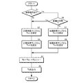
次に、図5を参照して操舵反力トルク設定部32における操舵反力トルク設定処理について説明する。操舵反力トルク設定部32は、自動車1がエンジンを始動すると、以下に述べる処理を所定のサイクルタイムで繰り返し実行する。
Next, the steering reaction force torque setting process in the steering reaction force
先ず、操舵反力トルク設定部32は、メインECU8からリヤトーコントロール装置11の故障信号Sfが入力されていないか否かを判定する(ステップ1)。故障信号Sfが入力されていない場合(No)、操舵反力トルク設定部32は、ヨーレイト成分設定部32aにおいて、図3(A)に示す正常時用のヨーレイト反力成分マップを参照してヨーレイト反力成分Tbγを設定し(ステップ2)、続いて、操舵角成分設定部32bにおいて、図4(A)に示す正常時用の操舵角反力成分マップを参照して操舵角反力成分Tbθを設定する(ステップ3)。そして、操舵反力トルク設定部32は、ヨーレイト反力成分Tbγや操舵角反力成分Tbθ等を加算して操舵反力トルクTbを求め(ステップ4)、操舵反力電流設定部33に操舵反力トルクTbを出力し(ステップ5)、本処理を繰り返す。
First, the steering reaction
一方、ステップ1でリヤトーコントロール装置11の故障信号Sfが入力されている場合(Yes)、操舵反力トルク設定部32は、左右の後輪5l,5rのトー角δrl,δrrが対称であるか否か、すなわち、ストロークセンサ17l,17rの検出結果から後輪5l,5rのトー角δrl,δrrが左右ともにトーインまたはトーアウト且つ同一転舵量であるか否かを判定する(ステップ6)。そして、左右の後輪5l,5rのトー角δrl,δrrが対称である場合(Yes)、操舵反力トルク設定部32は、ステップ2からステップ5の処理を行い、本処理を繰り返す。
On the other hand, when the failure signal Sf of the rear
ステップ6で左右の後輪5l,5rのトー角δrl,δrrが非対称である場合(No)、操舵反力トルク設定部32は、ヨーレイト成分設定部32aにおいて、図3(B)に示す故障時用のヨーレイト反力成分マップを参照してヨーレイト反力成分Tbγを設定し(ステップ7)、続いて操舵角成分設定部32bにおいて、図4(B)に示す故障時用の操舵角反力成分マップを参照して操舵角反力成分Tbθを設定する(ステップ8)。その後、ステップ4およびステップ5の処理を行い、本処理を繰り返す。
When the toe angles δrl and δrr of the left and right
このように、リヤトーコントロール装置11が故障した場合に、ヨーレイト成分設定部32aが、図3(B)に示す故障時用のヨーレイト反力成分マップに切り替え、ヨーレイト反力成分Tbγを正常時よりも大きく設定することにより、リヤトーコントロール装置11の故障に起因するヨーモーメントを打ち消す修正操舵を運転者が行い易くなる。また、リヤトーコントロール装置11が故障した場合に、操舵角成分設定部32bが、図4(B)に示す故障時用の操舵角反力成分マップに切り替え、操舵角反力成分Tbθを正常時よりも小さく設定することによっても、リヤトーコントロール装置11の故障による修正操舵を運転者が行い易くなる。
In this way, when the rear
そして、リヤトーコントロール装置11が故障しても、故障時の後輪5l,5rのトー角δrl,δrrが左右対称である場合に、操舵反力トルク設定部32が、図3(A)の正常時用のヨーレイト反力成分マップ、および図4(A)の正常時用の操舵角反力成分マップを参照して操舵反力トルクTbを設定するため、電動パワーステアリング装置21は、不要なヨーモーメントを車体2に作用させることのない適正な制御を行い得るようになっている。
Even if the rear
したがって、リヤトーコントロール装置11が故障した場合であっても、電動パワーステアリング装置21の操舵反力は運転者の操舵意思を重視して適正に制御され、運転者は、故障に起因するヨーモーメントを打ち消す修正操舵を容易に行うことができる。
Therefore, even if the rear
以上で具体的実施形態の説明を終えるが、本発明は上記実施形態に限定されることなく幅広く変形実施することができ、本発明の趣旨を逸脱しない範囲であれば種々の変更が可能である。例えば、上記実施形態の自動車は、RTC(リヤトーコントロールシステム)を搭載しているが、これをAFS(アクティブ・フロント・ステアリング)装置に変更したり、エンジンから駆動輪に伝達される駆動力を左右に配分する左右駆動力配分装置(ATTS:Active Torque Transfer System)等の車輪前後力制御装置に変更したりしてもよい。AFSを搭載する場合、ステアリング操舵角0の状態での前輪舵角がずれた状態、すわなち、ステアリングホイールが中立位置となるときに前輪が転舵された状態でAFSが失陥した場合に、電動パワーステアリングを同様に制御すればよい。一方、ATTS等を搭載する場合、左右の駆動輪に伝達される駆動力が左右均等でない状態、すなわち、ステアリング操舵量0の状態でも車体にヨーモーメントが発生して直進走行できない状態でATTSが失陥した場合に、電動パワーステアリングを同様に制御すればよい。 Although the description of the specific embodiment is finished as described above, the present invention can be widely modified without being limited to the above embodiment, and various modifications can be made without departing from the gist of the present invention. . For example, the automobile of the above embodiment is equipped with an RTC (rear toe control system), but this can be changed to an AFS (active front steering) device, or the driving force transmitted from the engine to the drive wheels can be changed. It may be changed to a wheel longitudinal force control device such as a left and right driving force distribution device (ATTS: Active Torque Transfer System). When AFS is installed, when the front wheel steering angle is shifted in a state where the steering steering angle is 0, that is, when the AFS is lost while the front wheel is steered when the steering wheel is in the neutral position. The electric power steering may be controlled similarly. On the other hand, when an ATTS or the like is mounted, the ATTS is lost when the driving force transmitted to the left and right driving wheels is not equal to the left and right, that is, when the yaw moment is generated in the vehicle body even when the steering amount is 0, and the vehicle cannot travel straight. In the event of a fall, the electric power steering may be controlled similarly.
1 自動車
2 車体
5 後輪
8 メインECU
9 操舵角センサ
11 リヤトーコントロール装置
12 電動アクチュエータ
15 ヨーレイトセンサ
17 ストロークセンサ(後輪トー角検出手段)
20 前輪操舵装置
21 電動パワーステアリング装置
22 ステアリングホイール
27 電動モータ(操舵アシスト用モータ)
28 EPS・ECU
32 操舵反力トルク設定部
32a ヨーレイト反力成分設定部
32b 操舵角反力成分設定部
35 出力電流制御部(モータ制御手段)
1 Car 2 Car body 5
9
20 Front
28 EPS / ECU
32 Steering reaction force torque setting unit 32a Yaw rate reaction force component setting unit 32b Steering angle reaction force
Claims (3)
車体のヨーレイトを検出するヨーレイト検出手段と、
前記操舵反力のうち、前記ヨーレイトに基づいて、該ヨーレイトを低減させる方向のヨーレイト反力成分を設定するヨーレイト成分設定部と、
少なくとも前記ヨーレイト反力成分に基づいて、前記操舵アシスト用モータを駆動制御するモータ制御手段と、
前記後輪のトー角を検出する後輪トー角検出手段とを備え、
前記ヨーレイト成分設定部は、前記リヤトーコントロール装置が故障し、前記後輪トー角検出手段によって検出された後輪のトー角が左右対称でない場合にのみ、当該リヤトーコントロール装置が正常な場合よりも前記ヨーレイト反力成分を大きく設定することを特徴とする電動パワーステアリング装置。 An electric power steering device that is mounted on a vehicle equipped with a rear toe control device that variably controls the toe angle of the rear wheel independently on the left and right sides and that can apply a steering reaction force to the steering wheel by a steering assist motor,
A yaw rate detecting means for detecting the yaw rate of the vehicle body;
A yaw rate component setting unit for setting a yaw rate reaction force component in a direction to reduce the yaw rate based on the yaw rate out of the steering reaction force;
Motor control means for driving and controlling the steering assist motor based on at least the yaw rate reaction force component ;
Rear wheel toe angle detecting means for detecting the toe angle of the rear wheel ,
The yaw rate component setting unit is more than when the rear toe control device is normal only when the rear toe control device fails and the rear wheel toe angle detected by the rear wheel toe angle detecting means is not symmetrical. An electric power steering apparatus characterized by setting a yaw rate reaction force component large.
前記操舵反力のうち、前記操舵角に基づいて、該操舵角を減少させる方向の操舵角反力成分を設定する操舵角成分設定部と
をさらに備え、
前記モータ制御手段は、さらに前記操舵角反力成分に基づいて、前記操舵アシスト用モータを駆動制御し、
前記操舵角成分設定部は、前記リヤトーコントロール装置が故障した場合、当該リヤトーコントロール装置が正常な場合よりも前記操舵角反力成分を小さく設定することを特徴とする、請求項1に記載の電動パワーステアリング装置。 Steering angle detection means for detecting the steering angle of the steering wheel;
A steering angle component setting unit configured to set a steering angle reaction force component in a direction of decreasing the steering angle based on the steering angle of the steering reaction force;
The motor control means further controls driving of the steering assist motor based on the steering angle reaction force component,
The steering angle component setting unit, when said rear toe control unit fails, characterized in that the rear toe control system is set small the steering angle reaction force component than the normal case, an electric according to claim 1 Power steering device.
Priority Applications (1)
| Application Number | Priority Date | Filing Date | Title |
|---|---|---|---|
| JP2009025856A JP5313714B2 (en) | 2009-02-06 | 2009-02-06 | Electric power steering device |
Applications Claiming Priority (1)
| Application Number | Priority Date | Filing Date | Title |
|---|---|---|---|
| JP2009025856A JP5313714B2 (en) | 2009-02-06 | 2009-02-06 | Electric power steering device |
Publications (2)
| Publication Number | Publication Date |
|---|---|
| JP2010179800A JP2010179800A (en) | 2010-08-19 |
| JP5313714B2 true JP5313714B2 (en) | 2013-10-09 |
Family
ID=42761669
Family Applications (1)
| Application Number | Title | Priority Date | Filing Date |
|---|---|---|---|
| JP2009025856A Expired - Fee Related JP5313714B2 (en) | 2009-02-06 | 2009-02-06 | Electric power steering device |
Country Status (1)
| Country | Link |
|---|---|
| JP (1) | JP5313714B2 (en) |
Families Citing this family (2)
| Publication number | Priority date | Publication date | Assignee | Title |
|---|---|---|---|---|
| CN104602988B (en) | 2012-09-04 | 2016-07-06 | 日产自动车株式会社 | Handling maneuver force control device |
| FR3101832B1 (en) | 2019-10-14 | 2024-08-09 | Renault Sas | High level controller of side assistance suitable for 4WD vehicles |
Family Cites Families (5)
| Publication number | Priority date | Publication date | Assignee | Title |
|---|---|---|---|---|
| JPH0558326A (en) * | 1991-09-04 | 1993-03-09 | Toyota Motor Corp | Power steering device |
| JPH05105100A (en) * | 1991-09-27 | 1993-04-27 | Honda Motor Co Ltd | Vehicle steering system |
| JP3409838B2 (en) * | 1998-08-19 | 2003-05-26 | トヨタ自動車株式会社 | Vehicle steering system |
| JP2007269062A (en) * | 2006-03-30 | 2007-10-18 | Honda Motor Co Ltd | Steering device of vehicle |
| JP2008280027A (en) * | 2007-04-11 | 2008-11-20 | Honda Motor Co Ltd | Electric power steering device |
-
2009
- 2009-02-06 JP JP2009025856A patent/JP5313714B2/en not_active Expired - Fee Related
Also Published As
| Publication number | Publication date |
|---|---|
| JP2010179800A (en) | 2010-08-19 |
Similar Documents
| Publication | Publication Date | Title |
|---|---|---|
| JP5432990B2 (en) | Rear wheel toe angle control device and electric actuator reference position calibration method in rear wheel toe angle control device | |
| JP5140662B2 (en) | Rear wheel steering vehicle | |
| WO2009104497A1 (en) | Rear wheel steering apparatus for a vehicle | |
| WO2010116605A1 (en) | Rear wheel toe angle control device for vehicle | |
| EP2236393B1 (en) | Rear wheel toe angle control system | |
| JP5313739B2 (en) | Rear wheel toe angle control device for vehicle | |
| JP4505508B2 (en) | Rear wheel toe angle variable vehicle | |
| JP5313714B2 (en) | Electric power steering device | |
| JP5271662B2 (en) | Power steering device | |
| JP4956477B2 (en) | Rear wheel toe angle controller | |
| JP5131681B2 (en) | Vehicle rear wheel toe angle variable control device | |
| JP5303333B2 (en) | Vehicle rear wheel steering control device | |
| JP5254143B2 (en) | Vehicle control device | |
| JP4359317B2 (en) | Steering system | |
| JP5326019B2 (en) | Rear wheel toe angle controller | |
| JP4722959B2 (en) | Rear wheel toe angle variable vehicle | |
| JP3995331B2 (en) | Vehicle steering system | |
| JP4702028B2 (en) | Vehicle travel control device | |
| JP2009234547A (en) | Rear wheel steering control device | |
| JP2008030610A (en) | Vehicle forward determination device | |
| JP2009214774A (en) | Rear wheel steering control device | |
| KR20190062756A (en) | Method for controlling steering angle of vehicle | |
| JP2010167814A (en) | Four-wheel steering device | |
| JP2021195096A (en) | Steering control device | |
| JP2010260459A (en) | Rear wheel toe angle control device and reference operation amount setting method for electric actuator |
Legal Events
| Date | Code | Title | Description |
|---|---|---|---|
| RD02 | Notification of acceptance of power of attorney |
Free format text: JAPANESE INTERMEDIATE CODE: A7422 Effective date: 20110924 |
|
| A621 | Written request for application examination |
Free format text: JAPANESE INTERMEDIATE CODE: A621 Effective date: 20111125 |
|
| A521 | Request for written amendment filed |
Free format text: JAPANESE INTERMEDIATE CODE: A523 Effective date: 20120522 |
|
| A977 | Report on retrieval |
Free format text: JAPANESE INTERMEDIATE CODE: A971007 Effective date: 20130228 |
|
| A131 | Notification of reasons for refusal |
Free format text: JAPANESE INTERMEDIATE CODE: A131 Effective date: 20130402 |
|
| A521 | Request for written amendment filed |
Free format text: JAPANESE INTERMEDIATE CODE: A523 Effective date: 20130528 |
|
| TRDD | Decision of grant or rejection written | ||
| A01 | Written decision to grant a patent or to grant a registration (utility model) |
Free format text: JAPANESE INTERMEDIATE CODE: A01 Effective date: 20130618 |
|
| A61 | First payment of annual fees (during grant procedure) |
Free format text: JAPANESE INTERMEDIATE CODE: A61 Effective date: 20130704 |
|
| R150 | Certificate of patent or registration of utility model |
Free format text: JAPANESE INTERMEDIATE CODE: R150 Ref document number: 5313714 Country of ref document: JP Free format text: JAPANESE INTERMEDIATE CODE: R150 |
|
| R250 | Receipt of annual fees |
Free format text: JAPANESE INTERMEDIATE CODE: R250 |
|
| LAPS | Cancellation because of no payment of annual fees |