JP5239656B2 - Image forming apparatus and belt apparatus - Google Patents
Image forming apparatus and belt apparatus Download PDFInfo
- Publication number
- JP5239656B2 JP5239656B2 JP2008229663A JP2008229663A JP5239656B2 JP 5239656 B2 JP5239656 B2 JP 5239656B2 JP 2008229663 A JP2008229663 A JP 2008229663A JP 2008229663 A JP2008229663 A JP 2008229663A JP 5239656 B2 JP5239656 B2 JP 5239656B2
- Authority
- JP
- Japan
- Prior art keywords
- belt
- fluctuation
- image forming
- roller
- forming apparatus
- Prior art date
- Legal status (The legal status is an assumption and is not a legal conclusion. Google has not performed a legal analysis and makes no representation as to the accuracy of the status listed.)
- Expired - Fee Related
Links
Images


Landscapes
- Handling Of Sheets (AREA)
- Electrostatic Charge, Transfer And Separation In Electrography (AREA)
- Control Or Security For Electrophotography (AREA)
- Delivering By Means Of Belts And Rollers (AREA)
Description
本発明は画像形成装置及びベルト装置に関する。 The present invention relates to an image forming apparatus and a belt apparatus.
プリンタ、ファクシミリ、複写装置、これらの複合機等の画像形成装置として、感光体ベルト、中間転写ベルト、紙搬送ベルトなどのベルト状部材を備えるものが知られている。なお、「画像形成」とは、文字や図形等の意味を持つ画像を媒体に対して付与することだけでなく、パターン等の意味を持たない画像を媒体に付与することなどを含み、印写、記録、印字、パターン形成、任意の位置への所望の機能を有する材料の付与(塗布)なども同義語で用いる。 2. Description of the Related Art As image forming apparatuses such as printers, facsimiles, copying machines, and multi-function machines, there are known ones including belt-like members such as a photoreceptor belt, an intermediate transfer belt, and a paper conveying belt. “Image formation” includes not only giving an image having a meaning such as a character or figure to a medium but also giving an image having no meaning such as a pattern to the medium. , Recording, printing, pattern formation, application of a material having a desired function to any position (application), etc. are also used synonymously.
例えば、直接転写方式のタンデム型画像形成装置は、搬送ベルトを用いて被記録媒体を搬送し、その搬送方向に沿って配置された互いに異なる単色の画像を形成する複数の画像形成ユニットを順次通過させ、被記録媒体上に各単色画像を重ね合わせて形成しカラー画像を得る、また、液滴を被記録媒体に吐出して画像を形成するインクジェット記録装置では、搬送ベルトを用いて被記録媒体の高い平面性で搬送して記録ヘッドから各色の液滴を吐出してカラー画像を形成する。 For example, a direct transfer tandem image forming apparatus transports a recording medium using a transport belt, and sequentially passes through a plurality of image forming units that form different monochrome images arranged along the transport direction. In an ink jet recording apparatus that forms a color image by superimposing each single color image on a recording medium and forming an image by discharging droplets onto the recording medium, the recording medium is A color image is formed by discharging the droplets of each color from the recording head while conveying with high flatness.
このような画像形成装置においては、色重ねずれなどを防止するために、ベルト状部材の高精度な移動制御を行わなければ成らない。 In such an image forming apparatus, it is necessary to perform highly accurate movement control of the belt-shaped member in order to prevent color misregistration and the like.
ところで、ベルトの移動速度は、様々な原因によって変動するが、その原因の中に、単層ベルトの場合にはベルト周方向におけるベルト厚みムラがある。このベルト厚みムラは、例えば、円筒金型を用いて遠心焼成方式で作成されたベルトにみられるベルト周方向にわたる肉厚の偏りによって生じる。このようなベルト厚みムラがベルトに存在すると、ベルトを駆動する駆動ローラ上にベルト厚の厚い部分が巻き付いているときにはベルト移動速度が速くなり、反対にベルト厚の薄い部分が巻き付いているときにはベルト移動速度が遅くなる。その結果、ベルト移動速度に変動が生じることになる。 By the way, although the moving speed of the belt fluctuates due to various causes, in the case of a single layer belt, there is uneven belt thickness in the belt circumferential direction. This unevenness in the belt thickness is caused by, for example, uneven thickness in the belt circumferential direction seen in a belt produced by a centrifugal firing method using a cylindrical mold. When such uneven belt thickness exists in the belt, the belt moving speed increases when a portion with a thick belt is wound around the driving roller that drives the belt, and conversely when the portion with a thin belt is wound. The moving speed becomes slow. As a result, the belt moving speed varies.
ここで、ベルト移動速度変動の理由について、具体的に説明する。
例えばタンデム型画像形成装置に用いられる中間転写ベルトの周方向におけるベルト厚みムラ(ベルト厚み偏差分布)の一例を図16に示している。この図16のグラフの横軸は、ベルト1周分の長さ(ベルト周長)を2π[rad]の角度に置き換えたものである。縦軸は、ベルト周方向におけるベルト平均厚み(100[μm])を基準(基準値0)としたベルト厚みの偏差値である。
Here, the reason for the belt movement speed fluctuation will be specifically described.
For example, FIG. 16 shows an example of belt thickness unevenness (belt thickness deviation distribution) in the circumferential direction of an intermediate transfer belt used in a tandem type image forming apparatus. The horizontal axis of the graph of FIG. 16 is obtained by replacing the length of one belt circumference (belt circumference) with an angle of 2π [rad]. The vertical axis represents the deviation value of the belt thickness with reference to the average belt thickness (100 [μm]) in the belt circumferential direction (reference value 0).
このようなベルト厚みムラをもつベルトにおいて、ベルト周方向1周分の偏差分布を「ベルト厚み変動」という。 In a belt having such belt thickness unevenness, the deviation distribution for one round in the belt circumferential direction is referred to as “belt thickness fluctuation”.
ここで、本願において用いる用語「ベルト厚みムラ」と「ベルト厚み変動」について説明する。
まず、「ベルト厚みムラ」とは、膜厚計測器等で測定されたベルトの厚み偏差分布を示し、ベルトの周方向(搬送経路方向)や奥行き方向(ローラ軸方向)にベルト厚みムラは存在する。一方、「ベルト厚み変動」とは、ベルト駆動制御装置に搭載された状態で、駆動ローラの回転角速度に対するベルト搬送速度やベルト搬送速度に対する従動ローラの回転角速度に影響を与え、ベルト回転周期の変動発生に起因するベルト厚み偏差分布を示すものである。
Here, the terms “belt thickness unevenness” and “belt thickness fluctuation” used in the present application will be described.
First, “belt thickness unevenness” refers to the belt thickness deviation distribution measured by a film thickness measuring instrument, etc., and there is belt thickness unevenness in the belt circumferential direction (conveyance path direction) and depth direction (roller axis direction). To do. On the other hand, “belt thickness fluctuation” means that the belt rotation speed of the driven roller relative to the rotational angular speed of the driving roller and the rotational angular speed of the driven roller relative to the belt conveyance speed are affected by fluctuations in the belt rotation cycle. It shows a belt thickness deviation distribution resulting from the occurrence.
また、図17に駆動ローラに巻き付いたベルト部分を、その駆動ローラの軸方向から見たときの説明図を示している。ベルト1003の移動速度は、ローラ1001の表面(ローラ表面)からベルトピッチ線までの距離、即ちピッチ線距離(以下、「PLD(Pitch Line Distance)」という。)によって決定される。このPLDは、ベルト1003が均一なベルト材質の単層ベルトであり、かつ、ベルト1003の内周面側と外周面側との伸縮度の絶対値がほぼ一致する場合、そのベルト厚み方向の中央とベルト内周面すなわちローラ表面との距離に相当する。したがって、単層ベルトの場合、PLDとベルト厚みとの関係がほぼ一定となるので、ベルト1003の移動速度はベルト厚み変動によって決定することもできる。
FIG. 17 shows an explanatory diagram when the belt portion wound around the driving roller is viewed from the axial direction of the driving roller. The moving speed of the
一方、複数層からなるベルトなどにおいては、硬質な層と軟質な層との間で互いに伸縮性が異なる結果、ベルト厚み方向の中央からずれた位置とローラ表面との距離がPLDとなる場合もある。 On the other hand, in a belt composed of a plurality of layers, the distance between the position shifted from the center in the belt thickness direction and the roller surface may be PLD as a result of the different stretchability between the hard layer and the soft layer. is there.
![]()
![]()
この(1)式における「PLDave」は、ベルト1周にわたるPLDの平均値であり、例えば平均厚みが100[μm]の単層ベルトの場合、PLDaveは50[μm]となる。 “PLDave” in the equation (1) is an average value of PLD over one belt. For example, in the case of a single layer belt having an average thickness of 100 [μm], PLDave is 50 [μm].
また、「f(d)」は、ベルト1周にわたるPLDの変動を示す関数である。
f(d)は、図16に示したベルト厚み偏差値と高い相関を持ち、ベルト1周を周期とする周期関数である。
Further, “f (d)” is a function indicating the fluctuation of the PLD over one belt revolution.
f (d) is a periodic function having a high correlation with the belt thickness deviation value shown in FIG.
ベルト周方向においてPLDが変動していると、駆動ローラの回転角速度又は回転角変位に対するベルト移動速度又はベルト移動距離、あるいは、ベルト移動速度又はベルト移動距離に対する従動ローラの回転角速度又は回転角変位が変動することになる。 If the PLD fluctuates in the belt circumferential direction, the rotational angular velocity or rotational angular displacement of the driven roller with respect to the rotational angular velocity or rotational displacement of the driving roller, or the belt traveling speed or the belt traveling distance with respect to the belt traveling speed or the belt traveling distance. Will fluctuate.
ベルト移動速度Vと駆動ローラ1001の回転角速度ωとの関係は、次に(2)式で表される。この式中の「r」は、駆動ローラ1001の半径である。また、PLDの変動を示すf(d)がベルトの移動速度又はベルト移動距離とローラの回転角速度又は回転角変位との関係に影響する度合いは、ローラに対するベルトの接触状態や巻付き量によって変化する場合がある。この影響度をPLD変動実効係数kで表す。
The relationship between the belt moving speed V and the rotational angular speed ω of the

以下、本明細書において、上記(2)式における{ }内をローラ実効半径といい、その定常部分(r+PLDave)をローラ実効半径Rとする。そして、f(d)をPLD変動という。 In the present specification, the inside of {} in the above formula (2) is referred to as a roller effective radius, and the steady portion (r + PLDave) is referred to as a roller effective radius R. F (d) is referred to as PLD fluctuation.
上記(2)式から、PLD変動f(d)が存在することにより、ベルト移動速度Vと駆動ローラ1001の回転角速度ωとの関係が変化することが分かる。つまり、駆動ローラ1001が一定の回転角速度(ω=一定)で回転していても、ベルト1003の移動速度VはPLD変動f(d)により変化する。
From the above equation (2), it can be seen that the presence of the PLD fluctuation f (d) changes the relationship between the belt moving speed V and the rotational angular speed ω of the
ここで、例えば単層ベルトの場合、ベルト平均厚みよりも厚いベルト部分が駆動ローラ1001に巻き付いている時には、ベルト1003の厚み偏差と相関の高いPLD変動f(d)が正の値をとり、ローラ実効半径が増加する。そのため、その駆動ローラ1001が一定の回転角速度(ω=一定)で回転していても、ベルト移動速度Vは増加する。逆に、ベルト平均厚みよりも薄いベルト部分が駆動ローラ1001に巻き付いているときには、ベルト厚み変動f(d)が負の値をとり、ローラ実効半径が減少する。そのため、その駆動ローラ1001が一定の回転角速度(ω=一定)で回転していても、ベルト移動速度Vは減少する。
Here, for example, in the case of a single layer belt, when a belt portion thicker than the belt average thickness is wound around the
このように、駆動ローラ1001の回転角速度ωを一定にしても、PLD変動f(d)によりベルト1001の移動速度は一定にならない。そのため、駆動ローラ1001の回転角速度ωだけからベルト1001の駆動を制御しようとしても、ベルト1001を所望の移動速度で駆動させることはできない。
Thus, even if the rotational angular velocity ω of the
また、ベルト移動速度Vと従動ローラの回転角速度との関係も、上述したベルト移動速度Vと駆動ローラ1001の回転角速度ωとの関係と同様である。つまり、従動ローラの回転角速度を回転型エンコーダ等により検出し、その検出した回転角速度からベルト移動速度Vを求める場合も、上記(2)式を用いることができる。
The relationship between the belt moving speed V and the rotational angular velocity of the driven roller is the same as the relationship between the belt moving speed V and the rotational angular velocity ω of the
したがって、例えば単層ベルトの場合、ベルト平均厚みよりも厚いベルト部分が従動ローラに巻き付いている時には、上記駆動ローラの場合と同様に、ベルトの厚み偏差と相関の高いPLD変動f(d)が正の値をとり、ローラ実効半径が増加する。そのため、ベルトが一定の移動速度(V=一定)で移動していても、従動ローラの回転角速度は減少する。逆に、ベルト平均厚みよりも薄いベルト部分が従動ローラに巻き付いている時には、PLD変動f(d)が負の値をとり、ローラ実効半径が減少する。そのため、ベルトが一定の移動速度で移動していても、従動ローラの回転角速度は増加する。 Therefore, for example, in the case of a single-layer belt, when a belt portion thicker than the average belt thickness is wound around the driven roller, the PLD fluctuation f (d) having a high correlation with the thickness deviation of the belt is generated as in the case of the driving roller. Takes a positive value and increases the effective roller radius. Therefore, even if the belt is moving at a constant moving speed (V = constant), the rotational angular speed of the driven roller decreases. On the contrary, when the belt portion thinner than the average belt thickness is wound around the driven roller, the PLD fluctuation f (d) takes a negative value and the effective roller radius decreases. Therefore, even if the belt moves at a constant moving speed, the rotational angular speed of the driven roller increases.
このように、ベルトの移動速度が一定であっても、PLD変動f(d)により従動ローラの回転角速度は一定とならない。そのため、従動ローラの回転角速度だけからベルト103の駆動を制御しようとしても、ベルトを所望の移動速度で駆動させることはできない。
Thus, even if the moving speed of the belt is constant, the rotational angular speed of the driven roller is not constant due to the PLD fluctuation f (d). Therefore, even if the drive of the
従来、このようなPLD変動f(d)を考慮してベルトの駆動制御を行うことが可能なものとして、例えば特許文献1には、PLD(ローラ表面からベルトピッチ線までの距離:ピッチ線距離)変動がベルト1周にわたりサイン波で発生しやすい遠心成形法で形成されたベルトを装置本体へ組込む前に、製造工程で予めベルト全周における厚みプロファイル(ベルト厚みムラ)を測定し、そのデータを記憶しておき、その全周の厚みプロファイルデータと実際のベルト厚みムラとの位相を合わせるための基準位置であるホームポジションとなる基準マークを付し、その位置を基準に検出することによって、ベルト厚み変動によるベルト移動速度の変動をキャンセルするようにベルト駆動制御を行うことが記載されている。
また、特許文献2には、検出用パターンをベルト上に形成して、これを検出センサで検出することにより、周期的なベルト移動速度の変動を検出することが記載されている。
また、特許文献3には、複数の支持回転体のうち回転駆動力の伝達に寄与しない従動支持回転体の回転角変位又は回転角速度を検出し、従動支持回転体の回転角変位又は回転角速度の検出結果から、ベルトの周方向の周期的な厚さ変動に対応した周波数を有する該回転角変位又は該回転角速度の交流成分を抽出し、交流成分の振幅及び位相に基づいて、駆動支持回転体の回転を制御することが記載されている。
特許文献4には、複数の支持回転体のうち、径が異なる、あるいはまた、自己に巻き付いたベルト部分のPLDがベルトの移動速度と自己の回転角速度との関係に影響する度合いが互いに異なる2つの支持回転体における回転角変位又は回転角速度の回転情報に基づいて、ベルトの周方向におけるPLD変動により生じるベルトの移動速度変動が小さくなるように、駆動支持回転体の回転制御を行う制御手段を有するものが記載されている。
特許文献5には、ベルトの基準位置となるマークを検出するマーク検出手段と、このマーク検出手段の出力信号を用いてベルトの厚み変動で発生するエンコーダの検出角変位誤差を検出する検出角変位誤差検出手段と、検出角変位誤差検出手段から得られるエンコーダの検出角変位誤差からそのマークまでの位相と最大振幅を算出する第1の算出手段と、第1の算出手段の算出結果が格納される不揮発性メモリと、メモリに格納された値を元にベルト上のマークからの距離に応じて補正データを算出する第2の算出手段と、補正データを格納する揮発性メモリとを有し、ベルトを駆動する時に、揮発性メモリに格納されている補正データを参照し、制御目標値に補正データを加算してベルト駆動手段を駆動制御することで、ベルトの厚みによる速度変動を安定化するものが記載されている。
しかしながら、特許文献1に記載の装置にあっては、ベルト製造段階においてベルト厚みムラを計測する計測工程が必要となり、またその計測工程において高精度なベルト厚み計測器が必要となる。そのため、製造コストが大幅に増大してしまうという問題がある。また、ベルトを新しいものに交換する際には、その新しいベルト固有の厚みプロファイルデータを装置へ入力する作業が必要となるという問題もある。さらに、この画像形成装置は、PLD変動f(d)を用いずにベルト厚みムラを用いるため、単層ベルトの場合には正確なベルト駆動制御が可能であるが、複数層ベルトの場合には正確なベルト駆動制御はできないという課題もある。
However, the apparatus described in
また、上記特許文献2に記載された装置にあっては、ベルト移動速度の変動を検出するのに、少なくともベルト1周分の検出用パターンをベルト上に形成する必要があるため、検出用パターンの形成のために多くのトナーを消費してしまうという問題がある。特に、ベルト移動速度の変動をより高い精度で検出するために、ベルト複数周分のベルト移動速度の変動情報の平均値をベルト移動速度の変動として把握する場合には、ベルト複数周分の検出用パターンを形成する必要があり、トナー消費の問題はより大きくなる。
In addition, in the apparatus described in
また、特許文献3に記載の装置にあっては、ベルト厚み変動をsin関数(cos関数)の周期関数に近似するので、ベルト厚み変動がベルト1周にわたってどのように発生しているかを予め知っておく必要があるという問題がある。つまり、ベルト厚み変動に含まれる周波数成分が、ベルトが1周する周期と同じ周期をもった基本周波数成分だけなのか、それともその高次周波数成分も含まれているのかなどを、予め知っておく必要があるという問題がある。このようなベルト厚み変動については、周期関数に近似することが難しく、その部分に制御誤差を含んでしまうという課題もある。
Further, in the apparatus described in
本発明は上記の課題に鑑みてなされたものであり、ベルトの厚み変動を関数ではなく定数として扱えるようにして、高精度にベルトの厚み変動による移動速度変動又は移動距離変動を取り除けるようにすることを目的とする。 The present invention has been made in view of the above-described problems, and enables the fluctuation of the moving speed or the moving distance due to the fluctuation of the belt thickness to be removed with high accuracy by treating the fluctuation of the belt thickness as a constant instead of a function. For the purpose.
上記の課題を解決するため、本発明に係る画像形成装置は、
少なくとも2つの支持回転体間に掛け回されて周回移動するベルト状部材と、
前記ベルト状部材を介して少なくとも1つの支持回転体に対向し、前記ベルト状部材の移動に伴って連れ回りする従動回転体と、
前記支持回転体及び前記従動回転体の回転角変位又は回転角速度から前記ベルト状部材の速度を算出し、当該算出結果に基づいて前記ベルト状部材の移動速度変動又は移動距離変動が小さくなるように前記ベルト状部材の移動制御を行う制御手段と、を備えている
構成とした。
In order to solve the above problems, an image forming apparatus according to the present invention provides:
A belt-like member that circulates between at least two supporting rotating bodies and moves around,
A driven rotor that opposes at least one support rotor via the belt-like member and rotates with the movement of the belt-like member;
The speed of the belt-shaped member is calculated from the rotational angular displacement or rotational angular velocity of the supporting rotating body and the driven rotating body, and the moving speed fluctuation or moving distance fluctuation of the belt-shaped member is reduced based on the calculation result. And a control means for controlling the movement of the belt-like member.
ここで、制御手段はベルト状部材が少なくとも1周するのに要する時間に相当する期間についての回転変動情報を所定のタイミングで求める処理を行い、かつ、回転変動情報を記憶する変動情報記憶手段を備えている構成とできる。この場合、変動情報記憶手段に記憶された回転変動情報は、支持回転体の回転角変位又は回転角速度を一定にしてベルト状部材を回転させたときの従動回転体の情報である構成とできる。また、従動回転体の回転角変位又は回転角速度を一定にしてベルト状部材を回転させたときの支持回転体の情報である構成とできる。 Here, the control means performs a process for obtaining rotation fluctuation information at a predetermined timing for a period corresponding to the time required for the belt-shaped member to make at least one turn, and also includes a fluctuation information storage means for storing the rotation fluctuation information. It can be configured as provided. In this case, the rotation fluctuation information stored in the fluctuation information storage means can be configured to be information on the driven rotor when the belt-shaped member is rotated with the rotation angle displacement or the rotation angular velocity of the support rotor being constant. Further, it can be configured as information on the supporting rotating body when the belt-shaped member is rotated with the rotational angular displacement or rotational angular velocity of the driven rotating body being constant.
また、制御手段は、回転変動情報から支持回転体の1回転を1周期とした交流成分を抽出し、支持回転体における速度又は移動距離に関する情報を補正し、支持回転体の変動により生じるベルト状部材の移動速度変動又は移動距離変動が小さくなるように動制御を行う構成とできる。 Further, the control means extracts an AC component with one rotation of the support rotator as one cycle from the rotation variation information, corrects information on the speed or movement distance in the support rotator, and generates a belt-like shape caused by the variation of the support rotator. It can be configured to perform dynamic control so that the movement speed fluctuation or movement distance fluctuation of the member is reduced.
また、制御手段は、回転変動情報から従動回転体の1回転を1周期とした交流成分を抽出し、従動回転体における速度又は移動距離に関する情報を補正し、従動回転体の変動により生じるベルト状部材の移動速度変動又は移動距離変動が小さくなるように駆動制御を行う構成とできる。 Further, the control means extracts an AC component with one rotation of the driven rotor as one cycle from the rotation fluctuation information, corrects information on the speed or moving distance of the driven rotor, and generates a belt-like shape caused by fluctuation of the driven rotor. The drive control can be performed so that the movement speed fluctuation or movement distance fluctuation of the member is reduced.
また、制御手段は、支持回転体と従動回転体のそれぞれの1回転を1周期とした周期を異ならせてそれぞれの交流成分を抽出し、支持回転体及び従動回転体の少なくともいずれかにおける速度または移動距離に関する情報を補正し、支持回転体及び従動回転体の少なくともいずれかの変動により生じるベルト状部材の移動速度変動又は移動距離変動が小さくなるように駆動制御を行う構成とできる。 Further, the control means extracts each AC component by changing the period in which one rotation of each of the support rotator and the driven rotator is one period, and extracts the speed of at least one of the support rotator and the driven rotator or It is possible to correct the information on the movement distance and perform drive control so that movement speed fluctuation or movement distance fluctuation of the belt-like member caused by fluctuation of at least one of the support rotating body and the driven rotation body is reduced.
また、回転変動情報から支持回転体及び従動回転体の少なくともいずれかの1回転を1周期とした交流成分を抽出し、抽出された交流成分を回転変動情報から除くことでベルト状部材の移動速度変動を得て、支持回転体における速度又は移動距離に関する情報を補正し、ベルト状部材の変動により生じるベルトの移動速度変動又は移動距離変動が小さくなるように駆動制御を行う構成とできる。 In addition, an AC component having one cycle of at least one of the support rotating body and the driven rotating body as one cycle is extracted from the rotation variation information, and the extracted AC component is removed from the rotation variation information to move the belt-shaped member. It is possible to obtain a variation, correct information regarding the speed or moving distance in the support rotating body, and perform drive control so that the moving speed variation or moving distance variation of the belt caused by the variation of the belt-like member is reduced.
また、制御手段は、所定のタイミングで回転変動情報を再び求める処理を行う構成とできる。この場合、制御手段は、変動情報記憶手段に記憶された回転変動情報と所定のタイミングで求めた回転変動情報との差が予め定めた許容範囲を超えたとき、回転変動情報を再度求める処理を行う構成とできる。また、制御手段は、回転変動情報を再度求める処理を行うときは所定のタイミングで行う処理より長い期間についての変動情報を記憶させる構成とできる。 Further, the control means can be configured to perform a process for obtaining rotation fluctuation information again at a predetermined timing. In this case, when the difference between the rotation fluctuation information stored in the fluctuation information storage means and the rotation fluctuation information obtained at a predetermined timing exceeds a predetermined allowable range, the control means performs processing for obtaining the rotation fluctuation information again. Can be configured to do. Further, the control means can be configured to store the fluctuation information for a longer period than the process performed at a predetermined timing when performing the process of obtaining the rotation fluctuation information again.
また、ベルト状部材は被記録媒体を搬送するベルトであって、制御手段は、被記録媒体を搬送していない所定のタイミングで回転変動情報を求める処理を行う構成とできる。 Further, the belt-like member is a belt that conveys the recording medium, and the control means can perform a process for obtaining rotation variation information at a predetermined timing when the recording medium is not conveyed.
本発明に係るベルト装置は、
少なくとも2つの支持回転体間に掛け回されて周回移動するベルト状部材と、
前記ベルト状部材を介して少なくとも1つの支持回転体に対向し、前記ベルト状部材の移動に伴って連れ回りする従動回転体と、
前記支持回転体及び前記従動回転体の回転角変位又は回転角速度から前記ベルト状部材の速度を算出し、当該算出結果に基づいて前記ベルト状部材の移動速度変動又は移動距離変動が小さくなるように前記ベルト状部材の移動制御を行う制御手段と、を備えている
構成とした。
The belt device according to the present invention is
A belt-like member that circulates between at least two supporting rotating bodies and moves around,
A driven rotor that opposes at least one support rotor via the belt-like member and rotates with the movement of the belt-like member;
The speed of the belt-shaped member is calculated from the rotational angular displacement or rotational angular velocity of the supporting rotating body and the driven rotating body, and the moving speed fluctuation or moving distance fluctuation of the belt-shaped member is reduced based on the calculation result. has a configuration which and a control means for controlling the movement of the belt-shaped member.
本発明に係る画像形成装置及びベルト装置によれば、回転角変位又は回転角速度を検出する2つの回転体はベルト状部材を挟んで対向しているので、ベルトの厚み変動j(t)がそれぞれの回転体に同時に作用し、これによって、それぞれのベルトの厚み変動の時間を同一とできるので厚み変動を関数ではなく定数として扱えるようになり、高精度にベルトの厚み変動による移動速度変動又は移動距離変動を取り除くことができる。 According to the image forming apparatus and the belt apparatus according to the present invention, the two rotating bodies that detect the rotation angle displacement or the rotation angular velocity are opposed to each other with the belt-shaped member interposed therebetween, and therefore the belt thickness variation j (t) is Since the time of thickness fluctuation of each belt can be made the same, the thickness fluctuation can be treated as a constant instead of a function, and the movement speed fluctuation or movement due to the belt thickness fluctuation can be performed with high accuracy. Distance variation can be removed.
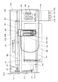
以下、本発明の実施の形態について添付図面を参照して説明する。先ず、本発明の第1実施形態について図1及び図2を参照して説明する。なお、図1は同実施形態に係るベルト装置に関わる部分の説明図、図2はベルト駆動機構部分の異なる例を示す模式的説明図である。 Embodiments of the present invention will be described below with reference to the accompanying drawings. First, a first embodiment of the present invention will be described with reference to FIGS. FIG. 1 is an explanatory view of a portion related to the belt device according to the embodiment, and FIG. 2 is a schematic explanatory view showing a different example of the belt drive mechanism portion.
このベルト装置では、図2(a)にも示すように、支持回転体としての第1ローラ1及び第2ローラ2間に無端状のベルト状部材であるベルト3が掛け回され、第1ローラ1を駆動ローラ、第2ローラ2を従動ローラとして回転駆動することにより、ベルト3が周回移動する。そして、第1ローラ1にベルト3を介して対向する従動回転体としての対向ローラ4を配置している。
In this belt device, as shown in FIG. 2A, a
なお、このベルト駆動機構としては、図2(b)に示すように、支持回転体としての第1ローラ1及び第2ローラ2、中間ローラ5間に無端状のベルト状部材であるベルト3が掛け回され、第1ローラ1を駆動ローラ、第2ローラ2、中間ローラ5を従動ローラとして回転駆動することにより、ベルト3が周回移動する構成とし、中間ローラ5にベルト3を介して対向する従動回転体としての対向ローラ4を配置することもできる。
As shown in FIG. 2B, the belt driving mechanism includes a
また、図2(c)に示すように、支持回転体としての第1ローラ1及び第2ローラ2間に無端状のベルト状部材であるベルト3が掛け回され、第1ローラ1を駆動ローラ、第2ローラ2を従動ローラとして回転駆動することにより、ベルト3が周回移動する構成とし、第2ローラ2にベルト3を介して対向する従動回転体としての対向ローラ4を配置することもできる。
Further, as shown in FIG. 2C, a
図1に戻って、第1ローラ1及び対向ローラ4には、検出手段としての回転型エンコーダ(ロータリエンコーダ)11、12がそれぞれ設けられている。各回転型エンコーダ11、12は軸方向で反対の側に設置されており、エンコーダ11、12とそれぞれのローラ1、4の干渉を防止している。また、十分な直径、例えば軸径の4倍の大きさで300lpiの回転エンコーダを備えている。これらの回転型エンコーダとしては、各ローラ1,4の回転角変位又は回転角速度が検知できるものであればよい。
Returning to FIG. 1, the
この回転型エンコーダ11、12としては、例えば、透明のガラス又はプラスチック等の透明部材で作られた円板上の同心円上に一定間隔のタイミングマークを形成したエンコーダホイール11a、12aを、各ローラ1、4に対して同軸に固定し、エンコーダホイール11a、12aのタイミングマークをフォトセンサ(エンコーダセンサ)11b、12bで光学的に検知する公知の光学エンコーダを用いている。なお、エンコーダホイール11a、12aには、それぞれ位置検出用マーク11m、12mが付されている。
As the
なお、例えば、磁性体からなる円盤上の同心円上に磁気的にタイミングマークを記録し、これを各ローラ1、4に対して同軸に固定し、そのタイミングマークを磁気ヘッドで検出するような磁気エンコーダを用いることもできる。また、公知のタコジェネレータを用いることもできる。
In addition, for example, a timing mark is magnetically recorded on concentric circles on a disk made of a magnetic material, and this is fixed to the
なお、ここでは、各ローラ1,4の回転角速度ω1,ω2を検知して用いるが、回転角速度は回転変位の時間関数であるので、回転変位を検知しても同様な効果が得られる。回転角変位は、回転型エンコーダ11、12から出力されるパルスの数をカウントすることによって得られる。
Here, the rotational angular velocities ω1 and ω2 of the
ベルト駆動制御部31は、制御手段であり、支持ローラ角速度検出部21及び対向ローラ角速度検出部22からの各角速度ω1、ω2に基づいて、ベルト3の移動速度変動又は移動速度距離変動が小さくなるように、第1のローラ1を回転駆動する駆動モータ32を、サーボアンプ33を介して駆動制御する。
The belt
なお、ベルト駆動機構の構成については上記のような構成に限られるものではなく、2つの回転体(支持回転体、従動回転体)がベルトを挟んで対向していればよい。また、対向ローラ4は、ベルト3の従動回転体であればよいが、被搬送物などの影響を受けないために非搬送経路に設けることが好ましい。
Note that the configuration of the belt drive mechanism is not limited to the above configuration, and it is sufficient that two rotating bodies (supporting rotating body and driven rotating body) face each other with the belt interposed therebetween. Further, the opposing roller 4 may be a driven rotating body of the
次に、この実施形態におけるベルト3の駆動制御について説明する。
上述したようにベルト3を架張している支持ローラ1、2のひとつ(ここでは第1ローラ1)と、その第1ローラ1にベルト3を挟んで圧接している対向ローラ4の2つローラの回転角速度ω1、ω2、又は、回転変位量x1,x2を連続的に検出し、この2種類の検出結果からベルトのPLD変動f(t)、及び、第1ローラ1の偏芯変動g(t)、及び、対向ローラ4の偏芯変動h(t)を求める。また、PLD変動f(t)を求めることなく、PLD変動f(t)の影響を取り除く。
Next, drive control of the
As described above, one of the supporting
PLD変動f(t)は、ベルトが1周する間に、ベルト移動経路上の特定地点を通過するベルト部分のPLDの時間変化を示す周期関数である。1周期内では特定できる規則性が少なく交流成分に分解して近似することは難しい。 The PLD fluctuation f (t) is a periodic function indicating the time change of the PLD of the belt portion that passes through a specific point on the belt moving path while the belt makes one round. There are few regularities that can be specified within one period, and it is difficult to decompose and approximate AC components.
第1ローラ1の偏芯変動g(t)は、第1ローラ1が一回転する間に、ベルト移動経路上の特定地点を通過する第1ローラ1部分の偏芯変動の時間変化を示す周期関数である。1回転を1周期とした正弦波に近似できる。
The eccentric fluctuation g (t) of the
対向ローラ4の偏芯変動g(t)は、偏心ローラが一回転する間に、ベルト移動経路上の特定地点を通過する従動ローラ部分の偏芯変動の時間変化を示す周期関数である。1回転を1周期とした正弦波に近似できる。 The eccentric variation g (t) of the facing roller 4 is a periodic function that indicates a temporal change in the eccentric variation of the driven roller portion that passes through a specific point on the belt moving path while the eccentric roller makes one rotation. It can be approximated to a sine wave with one rotation as one cycle.
PLD変動f(t)と第1ローラ1の偏芯変動g(t)と対向ローラ4の偏芯変動h(t)は、ベルト3の移動速度V又は移動距離Xに大きく影響するので、このPLD変動f(t)と第1ローラ1の偏芯変動g(t)と対向ローラ4の偏芯変動h(t)を2つのローラ1、4の回転角速度ω1,ω2又は回転変位量x1、x2から高精度で求め、そのPLD変動f(t)に基づいてベルト3の駆動制御を行うことで、ベルト3の移動速度Vを高い精度で制御することができる。
Since the PLD fluctuation f (t), the eccentric fluctuation g (t) of the
そこで、第1ローラの偏芯変動g(t)と従動ローラの偏芯変動h(t)を影響のない範囲の精度で製造したときのベルトのPLD変動f(t)を除去する例について説明する。
先ず、図3に第1ローラ1及び対向ローラ4とベルトの拡大図を示す。
ベルトのPLDはベルトの厚みとベルトの層構造に相関がありベルトの厚みTにより近似できる。例えば単層構造の場合はほぼベルトの厚みの半分となり、PLD=T/2、と表せる。この1/2は、ベルトの構造によって決まる定数であるので、PLD厚み定数としてαで表すと、PLDは、次に(3)式で表せる。
Therefore, an example of removing the PLD fluctuation f (t) of the belt when the eccentric fluctuation g (t) of the first roller and the eccentric fluctuation h (t) of the driven roller are manufactured with accuracy within a range that does not affect the first roller will be described. To do.
First, FIG. 3 shows an enlarged view of the
The belt PLD has a correlation with the belt thickness and the belt layer structure, and can be approximated by the belt thickness T. For example, in the case of a single layer structure, it is approximately half the thickness of the belt, and can be expressed as PLD = T / 2. Since 1/2 is a constant determined by the structure of the belt, when expressed as α as the PLD thickness constant, PLD can be expressed by the following equation (3).
例えば単層もしくは多層においても層の部材同士のヤング率が影響のない範囲で近い値であれば、αは1/2となる。また、複数層のベルトにおいては、PLDはヤング率が高い層にあり、その層の中央にPLDに設定することもできるが、ヤング率が比較的近い層が複数ある場合は複数層の場合は実験的に求めてもよい。 For example, even in a single layer or multiple layers, α is ½ if the Young's modulus between the members of the layers is a value close to a range that does not have an influence. In a multi-layer belt, the PLD is in a layer having a high Young's modulus, and can be set to the PLD in the center of the layer. However, when there are a plurality of layers having relatively close Young's moduli, It may be determined experimentally.
また、PLDはベルトの厚みTと強い相関があるので、PLD変動によるPLD厚み定数αの変化は無視できる程度である。したがって、PLD変動f(t)はベルトの厚み変動をj(t)とすると、次に(4)式で近似できる。 Further, since PLD has a strong correlation with belt thickness T, a change in PLD thickness constant α due to PLD fluctuation is negligible. Therefore, the PLD fluctuation f (t) can be approximated by the following equation (4), where j (t) is the belt thickness fluctuation.
PLD厚み定数αとベルトの厚みTは予め設定した所定の定数であるが、値を適宣選定できるように、調整可能にすることが好ましい。ここでは、ベルトの厚みTの設定値をtとして表す。 The PLD thickness constant α and the belt thickness T are predetermined constants set in advance, but it is preferable that the values can be adjusted so that the values can be appropriately selected. Here, the set value of the belt thickness T is expressed as t.
詳細は後述するが、(4)式によりPLD変動f(t)をベルトの厚み変動をj(t)に変換すると、ベルトの真の速度をVrとすると、第1ローラ1で検出される速度V1は、(5)式で表される。
Although details will be described later, when the PLD fluctuation f (t) is converted into the belt thickness fluctuation j (t) by the equation (4), the speed detected by the
ここで、ra:第1ローラ1の半径、t:ベルトの厚み設定値(予め設定している定数)、α :PLD厚み定数、V1:第1ローラ1で検出される速度、Vr:ベルトの真の速度、j(t):ベルトの厚み変動(時間の関数)である。
Here, ra: radius of the
これは、ベルトの厚み変動j(t)により速度を検知している第1ローラ1の回転角速度ω1が見かけ上、変化するためである。
This is because the rotational angular velocity ω1 of the
次に、(5)式の詳細について説明する。
第1ローラ1の回転角速度ω1とベルト移動速度V1との関係は、(6)式で表される。
Next, details of equation (5) will be described.
The relationship between the rotational angular velocity ω1 of the
第1ローラ1のベルト移動検出速度V1は、ベルトの厚み設定値(予め設定している定数)をtとすると、次の(7)式で表される。
The belt movement detection speed V1 of the
ここで、(7)式のω1を(6)式に代入すると、前述した次の(5)式になる。 Here, when ω1 in the equation (7) is substituted into the equation (6), the following equation (5) is obtained.
つまり、ω1はベルトの厚み変動j(t)がベルトの厚み設定値tより大きくなると第1ローラ1で検出される速度V1はベルトの真の速度Vrより小さくなる。
In other words, when the belt thickness variation j (t) becomes larger than the belt thickness setting value t, the speed V1 detected by the
次に、対向ローラ4で検出される速度(ベルト表面の速度となる)V2の関係を示す。対向ローラ4で検出される速度(ベルト表面の速度となる)V2は、(8)式で表される。 Next, the relationship of the speed V2 (which becomes the speed of the belt surface) detected by the facing roller 4 is shown. The speed V2 detected by the facing roller 4 (which is the speed of the belt surface) is expressed by the equation (8).
(6)式を(8)式に代入すると、(9)式となる。 Substituting equation (6) into equation (8) yields equation (9).
つまり、対向ローラ4で検出されるベルト表面の速度V2はベルトの厚み変動j(t)が大きくなると大きくなる。 That is, the speed V2 of the belt surface detected by the facing roller 4 increases as the belt thickness fluctuation j (t) increases.
したがって、速度V1、V2は、振幅は異なるが、波の周期が同じで、かつ、逆位相の速度変動をとることになる。この逆位相の波を足し合わすことによりベルトの厚み変動j(t)を取り除くことができる。 Therefore, the speeds V1 and V2 have different amplitudes but have the same wave period and take speed fluctuations in opposite phases. The thickness variation j (t) of the belt can be removed by adding the waves having opposite phases.
このように、本発明では、支持ローラと対向ローラがベルトを挟んで対向しているので、ベルトの厚み変動j(t)がそれぞれのローラに同時に作用する。よって、それぞれのベルトの厚み変動j(t)の時間を同一とできるので、厚み変動j(t)を関数ではなく定数として扱うことができ、これにより、従来なしえなかった精度でベルトの厚み変動j(t)を取り除くことが可能となる。 As described above, in the present invention, since the support roller and the opposing roller are opposed to each other with the belt interposed therebetween, the belt thickness variation j (t) acts on each roller simultaneously. Therefore, since the time of the thickness variation j (t) of each belt can be made the same, the thickness variation j (t) can be treated as a constant instead of a function, and thereby the belt thickness can be achieved with an accuracy that could not be achieved conventionally. The fluctuation j (t) can be removed.
具体的には、(9)式を、j(t)について展開すると、(10)式になる。 Specifically, when formula (9) is expanded for j (t), formula (10) is obtained.
これを(5)式のj(t)に代入する。代入された式は、Vrについての2次方程式で(11)式で表せる。そして、2次方程式をVrについて解くと、(12)式が得られる。 This is substituted for j (t) in equation (5). The substituted equation is a quadratic equation for Vr and can be expressed by equation (11). Then, when the quadratic equation is solved for Vr, equation (12) is obtained.
この(12)式で、速度V1と速度V2以外は定数であるので、ベルトの真の速度Vrは、(12)式に速度V1と速度V2を代入することで求められる。よって、ベルトの厚み変動j(t)に関係なく求めることが可能となる。 Since the expression (12) is a constant other than the speed V1 and the speed V2, the true speed Vr of the belt can be obtained by substituting the speed V1 and the speed V2 into the expression (12). Therefore, it can be obtained regardless of the belt thickness variation j (t).
速度Vrへの変換方法としては、速度V1と速度V2の値に対してVrをテーブル化しておき、速度V1と速度V2の値に応じてテーブルから真の速度Vrを求めるようにすることもできる。 As a conversion method to the speed Vr, Vr can be tabulated for the values of the speed V1 and the speed V2, and the true speed Vr can be obtained from the table according to the values of the speed V1 and the speed V2. .
また、ベルトの変位量は、速度の時間での積分値であるので、本発明によりベルトの厚み変動j(t)に関係なく求めることが可能となる。 Further, since the amount of displacement of the belt is an integral value over the time of speed, the present invention can be obtained regardless of the belt thickness fluctuation j (t).
真の速度Vrと同様に速度V1と速度V2の値に対して真の移動距離Xrをテーブル化しておき、速度V1と速度V2の値に応じてテーブルからの情報を基に真の移動距離Xrを求めるようにすることができる。 Like the true speed Vr, the true movement distance Xr is tabulated for the values of the speed V1 and the speed V2, and the true movement distance Xr is based on the information from the table according to the values of the speed V1 and the speed V2. Can be requested.
次に、ベルト表面の速度V2と対向ローラ4の回転角速度ω2との関係を説明する。
対向ローラ4の回転角速度ω2とベルト表面の速度V2の関係は、次の(13)式で表される。
Next, the relationship between the belt surface speed V2 and the rotational angular speed ω2 of the counter roller 4 will be described.
The relationship between the rotational angular velocity ω2 of the facing roller 4 and the belt surface speed V2 is expressed by the following equation (13).
ここで、ω2:対向ローラ4の回転角速度、rb:対向ローラ4の回転半径、V2:対向ローラ4で検出される速度(ベルト表面の速度となる)である。 Here, ω2 is the rotational angular velocity of the opposing roller 4, rb is the rotational radius of the opposing roller 4, and V2 is the speed detected by the opposing roller 4 (becomes the speed of the belt surface).
(14)式によりベルト表面の速度V2は対向ローラ4の回転角速度ω2により求めることができる。 The speed V2 of the belt surface can be obtained from the rotational angular speed ω2 of the facing roller 4 from the equation (14).
このように、少なくとも2つの支持回転体間に掛け回されて周回移動するベルト状部材と、ベルト状部材を介して少なくとも1つの支持回転体に対向し、ベルト状部材の移動に伴って連れ回りする従動回転体と、支持回転体及び従動回転体の回転角変位又は回転角速度に基づいてベルト状部材の移動速度変動又は移動距離変動が小さくなるようにベルト状部材の移動制御を行う制御手段とを備えることで、回転角変位を検出する2つの回転体はベルト状部材を挟んで対向していることで、ベルトの厚み変動j(t)がそれぞれの回転体に同時に作用し、これによって、それぞれのベルトの厚み変動j(t)の時間を同一とできるので厚み変動j(t)を関数ではなく定数として扱えるようになり、高精度にベルトの厚み変動j(t)による移動速度変動又は移動距離変動を取り除くことができる。 As described above, the belt-like member that circulates and moves between at least two support rotators, and faces the at least one support rotator via the belt-like member, and rotates with the movement of the belt-like member. And a control means for controlling the movement of the belt-shaped member so that the movement speed fluctuation or the movement distance fluctuation of the belt-shaped member is reduced based on the rotation angular displacement or the rotation angular velocity of the support rotation body and the driven rotation body. By providing the two rotating bodies that detect the rotational angular displacement, the belt thickness variation j (t) acts simultaneously on each rotating body by sandwiching the belt-shaped member therebetween, thereby Since the time of the thickness variation j (t) of each belt can be made the same, the thickness variation j (t) can be treated as a constant instead of a function, and the transfer due to the belt thickness variation j (t) can be performed with high accuracy. It can be removed the speed variation or moving distance variation.
次に、本発明の第2実施形態について図4を参照して説明する。なお、図4は同実施形態に係る画像形成装置におけるベルト駆動制御に関わる部分の説明図である。
ここでは、回転型エンコーダ11のセンサ11cから出力されるパルスに基づいて第1のローラ1の円周位置を検出する支持ローラ円周位置検出部23と、回転型エンコーダ12のセンサ12cから出力されるパルスに基づいて対向ローラ4の円周位置を検出する対向ローラ円周位置検出部24とを備えている。
Next, a second embodiment of the present invention will be described with reference to FIG. FIG. 4 is an explanatory diagram of a portion related to belt drive control in the image forming apparatus according to the embodiment.
Here, the support roller
また、ベルト駆動制御部31には、ベルト3が少なくとも1周するのに要する時間に相当する期間についての回転変動情報を記憶する変動情報記憶手段としての変動情報記憶部41と、変動補正処理部42とを備えている。また、ベルト3に位置検出用マーク3mが設けられ、この位置検出用マーク3mを検出するベルト円周位置検出手段13を備えている。
Further, the belt
この実施形態では、ベルトの厚み変動j(t)の他、第1のローラ(支持ローラ)1の偏芯変動g(t)、及び、対向ローラ4の偏芯変動h(t)を求めるようにしている。 In this embodiment, in addition to the belt thickness variation j (t), the eccentric variation g (t) of the first roller (support roller) 1 and the eccentric variation h (t) of the opposing roller 4 are obtained. I have to.
つまり、図5を参照して、第1のローラ1の回転角側を一定に保ったときの対向ローラ4で検出される速度V2の値を示したもので、横軸に時間t、縦軸に速度変動を表している。なお、t1はベルト3の1周期当たりの周期、t2は第1のローラ1の1周期当たりの周期、t3は対向ローラ4の1周期あたりの周期である。また、図5において、実線は速度V2の出力値、破線は第1のローラ1の偏芯成分の速度変動、二点鎖線はベルト3の厚み変動による速度変動を示している。このように、第1のローラ1、対向ローラ4、ベルト3は、周期t1、t2、t3が異なるので、容易に、第1のローラ(支持ローラ)1の偏芯変動g(t)、対向ローラ(従動回転体)2の偏芯変動h(t)を求めることができる。
That is, referring to FIG. 5, the value of the speed V2 detected by the facing roller 4 when the rotation angle side of the
ローラ1、4の速度変動成分のほとんどは偏芯によるものであるので、図5に示す速度データをフーリエ変換等により特定周波数の交流成分を抽出し、変動情報記憶部41にそれぞれ別々に記憶する。
Since most of the speed fluctuation components of the
また、2つのローラ1,4の周波数成分を取り除いた値をベルトの厚み変動j(t)による速度変動として変動情報記憶部41に記憶する。もしくは、PLD変動f(t)として、(4)式にて求めてf(t)として記憶することもできる。ベルトの厚み変動f(t)による速度変動は交流周期での規則性が少なく、全速度変動成分からローラの速度変動成分を取り除くことで求める方が好ましい。
Further, the value obtained by removing the frequency components of the two
また、2つのローラ1,4はベルト3を挟んで対向しているので、ベルト3の厚み変動j(t)が同時に作用する。そのため、それぞれに作用するベルトの厚み変動j(t)を関数ではなく定数として扱える。その作用により、正確に3つの変動成分に分解できる。
Further, since the two
これにより、図5に示す速度変動成分は、図6に示すベルトの厚み変動j(t)の速度変動、図7に示す第1のローラ(支持ローラ)1の偏芯変動g(t)の速度変動、図8に示す対向ローラ(従動回転体)4の偏芯変動h(t)の速度変動に、正確に分解することができる。 As a result, the speed fluctuation component shown in FIG. 5 includes the speed fluctuation of the belt thickness fluctuation j (t) shown in FIG. 6 and the eccentric fluctuation g (t) of the first roller (support roller) 1 shown in FIG. It can be accurately decomposed into the speed fluctuation, that is, the speed fluctuation of the eccentric fluctuation h (t) of the opposing roller (driven rotor) 4 shown in FIG.
そこで、この変動成分をそれぞれ変動情報記憶部41に記憶する。変動成分は速度変動又は移動距離変動に関する情報であればどのように記憶してもよい。そして、この変動情報記憶部41に記憶した変動成分に関する情報に基づいて変動補正処理部42によってベルトの移動速度変動又は移動距離変動が小さくなるように駆動モータ32を駆動制御する。
Therefore, each fluctuation component is stored in the fluctuation
なお、本実施形態とは異なりベルト周方向の別の場所に2つのローラを配置し、それぞれ別々のベルト周方向の場所で速度を検出した場合、ベルトの厚み変動j(t)がローラに対し別々に作用するため本発明のようにベルトの厚み変動j(t)を正確に求めることは容易ではない。また、本発明では周期と波形(正弦波)が比較的正確に求められる各ローラの変動成分を全体の速度変動から取り除いてベルトの変動周期としているが、従来ではベルトの変動成分を周期を特定して求めなければならなったため、ベルトの変動周期を予め予測する必要があり、予測周期と異なる変動は検出できない。また、正弦波以外の変動は検出できない。ベルトの厚み変動j(t)は製造の際に偶発的に発生するものであり全ての周期を予測することは非常に困難である。 Unlike this embodiment, when two rollers are arranged at different locations in the belt circumferential direction and the speed is detected at different locations in the belt circumferential direction, the belt thickness fluctuation j (t) Since they work separately, it is not easy to accurately obtain the belt thickness variation j (t) as in the present invention. In the present invention, the fluctuation component of each roller whose period and waveform (sinusoidal wave) are relatively accurately obtained is removed from the overall speed fluctuation to obtain the belt fluctuation period. Conventionally, the belt fluctuation component is specified as the period. Therefore, it is necessary to predict the fluctuation period of the belt in advance, and fluctuations different from the prediction period cannot be detected. In addition, fluctuations other than sine waves cannot be detected. The belt thickness variation j (t) occurs accidentally during production, and it is very difficult to predict the entire period.
上述した例では、第1のローラ1の回転角側を一定に保ったときの対向ローラ4で検出される速度V2の値を示しているが、これに加え、対向ローラ4の回転角側を一定に保ったときの第1のローラ1で検出される速度V1の値を求め、2つを比較することでより精度のよい変動成分の分解が可能となる。
In the example described above, the value of the speed V2 detected by the facing roller 4 when the rotation angle side of the
また、第1のローラ1又は対向ローラ4を一定に保つ方法で説明したが、速度を一定に保つのが難しい場合は、駆動しているローラの回転速度変動も記憶し、もう一方のローラで検出された速度変動データからそのデータを予め取り除いた後、前述した第1のローラ1又は対向ローラ4の回転角側を一定に保ったときの処理を行うようにしてもよい。
Also, the method of keeping the
さらに、第1のローラ1、対向ローラ4、ベルト3の一周当たりの相対位置を特定でききる位置検出手段としての上記円周位置検出部23、24を備えることで、その位置情報と記憶された、それぞれの変動成分によりベルトの移動速度変動又は移動距離変動が小さくなるように、駆動制御を行うことが可能となる。
Furthermore, by providing the
例えば、検出された速度情報又は移動距離情報から記憶されたそれぞれの変動成分を取り除くことで変動の影響のない駆動制御を行うことが可能となる。 For example, it is possible to perform drive control without the influence of fluctuations by removing the respective fluctuation components stored from the detected speed information or movement distance information.
また、記憶する変動成分、もしくは周方向の位置検出手段は適宣選定可能であり、上記実施形態に限定されるものではない。例えば、第1のローラ1とベルト3の変動成分のみ記憶し、また位置検出手段を設け、第1のローラ1の回転角速度情報のみでベルト3の移動速度変動又は移動距離変動が小さくなるように、駆動制御を行うことが可能となる。
Further, the fluctuation component to be stored or the position detection means in the circumferential direction can be appropriately selected, and is not limited to the above embodiment. For example, only the fluctuation components of the
例えば、第1のローラ1と対向ローラ4の変動成分のみ記憶し、また位置検出手段を設け、ベルト3の変動成分は前記第1実施形態で説明した処理で変動成分を取り除き、ベルト3の移動速度変動又は移動距離変動が小さくなるように、駆動制御を行うことが可能となる。
For example, only the fluctuation components of the
次に、ベルトの移動速度変動成分又は移動距離変動成分を求めるタイミングについて図9のフロー図を参照して説明する。
ここでは、ベルトの移動速度変動成分又は移動距離変動成分は、装置本体の電源投入時のイニシャライズ処理に行うようにしている。これにより、このときは少なくとも搬送物が搬送されていないので駆動負荷が一定に安定し、ローラ回転数が安定した領域で測定可能となる。
Next, timing for obtaining the moving speed fluctuation component or the moving distance fluctuation component of the belt will be described with reference to the flowchart of FIG.
Here, the moving speed fluctuation component or the moving distance fluctuation component of the belt is applied to the initialization process when the apparatus main body is turned on. Accordingly, at this time, since at least the conveyed product is not conveyed, the driving load is stably stabilized, and measurement can be performed in a region where the roller rotation speed is stable.
つまり、電源オンになると、速度変動を確認し、変動が許容値内でなければ(許容値を超えていれば)、再度速度変動を確認し、変動値が信頼できると判別されたときには変動情報データを書換え、信頼できないと判別されたときにはエラー表示を行うようにしている。 In other words, when the power is turned on, the speed fluctuation is confirmed. If the fluctuation is not within the allowable value (exceeding the allowable value), the speed fluctuation is confirmed again, and if it is determined that the fluctuation value is reliable, the fluctuation information The data is rewritten and an error is displayed when it is determined that the data is not reliable.
また、画像情報の乱れをユーザーやサービスマンが認識し、装置本体の操作部やホスト(情報処理装置)側のドライバからユーザーが変動成分を求めるモードを指示することで、図9に示すモード信号入力によって、上述した処理を行うようにすることもできる。 Further, the user or serviceman recognizes the disturbance of the image information, and the mode signal shown in FIG. The above-described processing can also be performed by input.
また、上記の処理では、毎回移動距離変動成分のデータを更新し記憶するのではなく、画像に影響がでると判断できる所定の許容値を設け、その値を超えたときは再度、移動距離変動成分を求めて確認し、再度、許容値を超えていたらデータを更新するようにしている。これにより、制御時間が短縮できる上に、誤検知も防止することができる。 In the above processing, instead of updating and storing the data of the movement distance variation component every time, a predetermined allowable value that can be determined to affect the image is provided, and when the value exceeds that value, the movement distance fluctuation is again detected. The component is obtained and checked, and the data is updated again if the allowable value is exceeded. As a result, the control time can be shortened and erroneous detection can also be prevented.
また、再度、繰り返される情報は、例えばベルト2周期分の速度変動を記憶し、1周期目と2周期目とそれぞれ変動成分を抽出し、その抽出された変動成分をローラ毎、ベルト毎でそれぞれ比較し、それぞれの速度変動が予め設定された許容値より小さい場合は検出結果が正しいと判断しデータを更新するようにしてもよい。これにより、さらに精度よく誤検知を防止することができる。 In addition, the information to be repeated again, for example, stores speed fluctuations for two belt cycles, extracts fluctuation components for the first and second periods, and extracts the fluctuation components for each roller and each belt. In comparison, if each speed fluctuation is smaller than a preset allowable value, it may be determined that the detection result is correct and the data may be updated. Thereby, erroneous detection can be prevented with higher accuracy.
このとき、1周期目と2周期目とのデータが異なる場合は、装置の操作部やホスト(情報処理装置)側のドライバ上でエラー表示を行うようにしてもよい。 At this time, if the data in the first period and the second period are different, error display may be performed on the operation unit of the apparatus or on the driver on the host (information processing apparatus) side.
次に、本発明を適用した画像形成装置の第1例について図10及び図11を参照して説明する。なお、図10は同画像形成装置の概略構成図、図11は同装置のタンデム画像形成部の拡大説明図である。
この画像形成装置は、タンデム型で中間転写(間接転写)方式の電子写真画像形成装置であり、装置本体100と、装置本体100を載置する給紙テーブル102と、装置本体100上に取り付けるスキャナ103と、スキャナ103上に取り付けた原稿自動搬送装置(ADF)104とを備えている。
Next, a first example of an image forming apparatus to which the present invention is applied will be described with reference to FIGS. 10 is a schematic configuration diagram of the image forming apparatus, and FIG. 11 is an enlarged explanatory diagram of a tandem image forming unit of the apparatus.
This image forming apparatus is an electrophotographic image forming apparatus of a tandem type and an intermediate transfer (indirect transfer) system, and includes an apparatus main body 100, a paper feed table 102 on which the apparatus main body 100 is placed, and a scanner attached on the apparatus main body 100. 103 and an automatic document feeder (ADF) 104 mounted on the
装置本体100には、その中央に、像担持体としての中間転写体であるベルト状部材である中間転写ベルト110が設けられている。この中間転写ベルト110は、3つの支持回転体としての支持ローラ114,115,116に掛け回されており、同図中時計回り方向に回転移動する。これらの3つの支持ローラのうちの第2支持ローラ115の図中左側には、画像転写後に中間転写ベルト110上に残留する残留トナーを除去する中間転写ベルトクリーニング装置117が設けられている。また、3つの支持ローラのうちの第1支持ローラ114と第2支持ローラ115との間に張り渡したベルト部分には、そのベルト移動方向に沿って、イエロー(Y)、マゼンタ(M)、シアン(C)、黒(K)の4つの画像形成部118が並べて配置されたタンデム画像形成部120が対向配置されている。なお、本実施形態においては、第3支持ローラ116を駆動ローラとしている。
In the center of the apparatus main body 100, an
また、タンデム画像形成部120の上方には、潜像形成手段としての露光装置121が設けられている。また、中間転写ベルト110を挟んでタンデム画像形成部120の反対側には、第2の転写手段としての2次転写装置122が設けられている。この2次転写装置122においては、2つのローラ123間に記録材搬送部材としてのベルト状部材である2次転写ベルト124が掛け渡されている。
An
この2次転写ベルト124は、中間転写ベルト110を介して第3支持ローラ116に押し当てられるように設けられている。この2次転写装置122により、中間転写ベルト110上の画像を被記録媒体(記録材)であるシートに転写する。また、この2次転写装置122の図中左方には、シート上に転写された画像を定着する定着装置125が設けられ、更に定着装置124の図中左方には排紙トレイ127が設けられている。
The
また、本実施形態では、このような2次転写装置122及び定着装置125の下に、上述したタンデム画像形成部120と平行に、シートの両面に画像を記録すべくシートを反転するシート反転装置128も設けられている。
In the present embodiment, a sheet reversing device that inverts the sheet to record images on both sides of the sheet in parallel with the above-described tandem
この画像形成装置を使用してコピーをとるときは、原稿自動搬送装置104又はスキャナ103の図示しないコンタクトガラス上に原稿をセットして、スキャナ103を駆動することにより、原稿内容を読み取る。この原稿読取りに並行して、図示しない駆動源である駆動モータで駆動ローラ116を回転駆動させる。これにより、中間転写ベルト110が図中時計回り方向に移動するとともに、この移動に伴って残り2つの支持ローラ(従動ローラ)114,115が連れ回り回転する。また、これと同時に、個々の画像形成部118において潜像担持体としての感光体ドラム140Y,140M,140C,140Kを回転させ、各感光体ドラム上に、イエロー、マゼンタ、シアン、黒の色別情報を用いてそれぞれ露光現像し、単色のトナー画像(顕像)を形成する。
When making a copy using this image forming apparatus, an original is set on a contact glass (not shown) of the
そして、各感光体ドラム140Y,140M,140C,140K上のトナー画像を中間転写ベルト110上に互いに重なり合うように順次転写して、中間転写ベルト110上に合成カラー画像を形成する。
Then, the toner images on the photosensitive drums 140Y, 140M, 140C, and 140K are sequentially transferred onto the
一方、給紙テーブル102の給紙カセット144から選択的にシートを繰り出して半走路145を介して装置本体100内の給紙路146に導き、レジストローラ149に突き当てて止める。
On the other hand, the sheet is selectively fed out from the
そして、中間転写ベルト110上の合成カラー画像にタイミングを合わせてレジストローラ149を回転し、中間転写ベルト110と2次転写装置122との間にシートを送り込み、2次転写装置122で転写してシート上にカラー画像を転写する。画像転写後のシートは、2次転写ベルト124で搬送して定着装置125へと送り込み、定着装置125で転写画像を定着して後、排出ローラで排紙トレイ127上にスタックし、あるいは、シート反転装置128に送り込んで反転して再び転写位置へと導き、裏面にも画像を記録した後排紙トレイ127上に排出する。
Then, the
なお、画像転写後の中間転写ベルト110は、中間転写ベルトクリーニング装置117で、画像転写後に中間転写ベルト110上に残留する残留トナーを除去し、タンデム画像形成部120による再度の画像形成に備える。
The
次に、本実施形態の中間転写ベルト110の構成について説明する。なお、以下の説明は、中間転写ベルトに限られるものではなく、広く、駆動制御がなされるベルトについて同様である。
中間転写ベルト110としては、フッ素系樹脂、ポリカーボネート樹脂、ポリイミド樹脂等を主材料とした単層ベルトや、ベルトの全層又はベルトの一部を弾性部材とした複数層弾性ベルトなどが使用される。中間転写ベルトに限らず、一般に、画像形成装置に用いられるベルトには複数の機能が要求される。
Next, the configuration of the
As the
そこで、要求される複数の機能を同時に達成するために、ベルト厚さ方向に複数の層を有する複数層ベルトが多く用いられる。例えば、中間転写ベルト110については、トナー離型性、感光体ニップ性、耐久性、抗張性、対駆動ローラ高摩擦性、対感光体低摩擦性などの複数の機能が要求される。
Therefore, in order to simultaneously achieve a plurality of required functions, a multi-layer belt having a plurality of layers in the belt thickness direction is often used. For example, the
トナー離型性は、中間転写ベルト110から記録用紙への転写性の向上や当該中間転写ベルト上に残った転写残トナーに対するクリーニング性の向上を図る上で必要な機能である。感光体ニップ性は、各感光体ドラム140y,140m,140c,140kに密着して中間転写ベルト110への転写性を向上させる上で必要な機能である。耐久性は、経時使用によって亀裂や磨耗が少なく長期的な使用を可能にし、ランニングコストを低減する上で必要な機能である。抗張性は、ベルト駆動時のベルト周方向における伸縮を防止して高精度なベルト移動速度やベルト移動位置の制御を行う上で必要な機能である。対駆動ローラ高摩擦性は、駆動ローラ116と中間転写ベルト110との間の滑りを防止して安定かつ高精度な駆動を実現する上で必要な機能である。対感光体低摩擦性は、感光体ドラム40Y,40M,40C,40Kと中間転写ベルト110との間に速度差が生じてもこれらの間で滑りを発生させて負荷変動を抑制する上で必要な機能である。これらの機能を高い水準で同時に実現するためには、例えば、以下に説明するような複数層ベルトからなる中間転写ベルトを用いる。
The toner releasability is a function necessary for improving the transferability from the
ここで、中間転写ベルト110の層構造の一例について図12の説明図を参照して説明する。
この中間転写ベルト110は、互いに異なる材質が異なる5層構造の無端状ベルトで、ベルトの厚みは500〜700[μm]以下となるように形成されたものである。なお、ベルト表面側(感光体ドラムと接触する面側)から順に、第1層、第2層、第3層、第4層、第5層とする。
Here, an example of the layer structure of the
The
第1層は、フッ素が充填されたポリウレタン樹脂のコート層である。この層により、感光体ドラム40Y,40M,40C,40Kと中間転写ベルト110との間の低摩擦性(対感光体低摩擦性)と、トナー離型性とが実現される。第2層は、シリコン−アクリル共重合体のコート層で、第1層の耐久性の向上と第3層の経時劣化を防止する役割を果たしている。第3層は、厚みが約400〜500[μm]のクロロプレンからなるゴム層(弾性層)で、ヤング率が1〜20[Mpa]である。第3層は、2次転写部においてトナー像や平滑性の悪い記録用紙などによる局部的な凹凸に応じて変形するので、トナー像に対して過度に転写圧を高めることがなく、文字の中抜けの発生が抑制される。また、平滑性の悪い記録用紙に対して良好な密着性が得られので、均一性の優れた転写画像を得ることができる。 The first layer is a polyurethane resin coat layer filled with fluorine. By this layer, low friction between the photosensitive drums 40Y, 40M, 40C, and 40K and the intermediate transfer belt 110 (anti-photosensitive member low friction) and toner releasability are realized. The second layer is a silicon-acrylic copolymer coat layer that plays a role in improving the durability of the first layer and preventing the third layer from aging. The third layer is a rubber layer (elastic layer) made of chloroprene having a thickness of about 400 to 500 [μm], and has a Young's modulus of 1 to 20 [Mpa]. Since the third layer is deformed in the secondary transfer portion according to local unevenness due to a toner image or recording paper having poor smoothness, the transfer pressure is not excessively increased with respect to the toner image. Occurrence of omission is suppressed. In addition, since good adhesion to a recording paper with poor smoothness is obtained, a transfer image with excellent uniformity can be obtained.
第4層は、厚みが約100[μm]のポリフッ化ビニリデンの層でベルト周方向の伸縮を防止する役割を果たしている。ヤング率は、500〜1000[Mpa]である。第5層は、ポリウレタンのコート層があり、駆動ローラ16との高摩擦性係数を実現している。 The fourth layer is a polyvinylidene fluoride layer having a thickness of about 100 [μm] and serves to prevent expansion and contraction in the belt circumferential direction. The Young's modulus is 500 to 1000 [Mpa]. The fifth layer has a polyurethane coat layer and realizes a high friction coefficient with the drive roller 16.
この他の材料例としては、次のものが挙げられる。
第1層及び第2層では、弾性材料による感光体への汚染防止と、中間転写ベルト110の表面への表面摩擦抵抗を低減させてトナーの付着力を小さくすることによるクリーニング性の向上と、記録用紙への2次転写性の向上と図るために、ポリウレタン、ポリエステル、エポキシ樹脂等を1種類あるいは2種類以上使用してもよい。また、表面エネルギーを小さくして潤滑性を高めるために、フッ素樹脂、フッ素化合物、フッ化炭素、2酸化チタン、シリコンカーバイト等の粉体若しくは粒子を1種類あるいは2種類以上、又は、互いに粒径が異なる同種のものを分散させてもよい。また、フッ素系ゴム材料のように熱処理を行うことで表面にフッ素リッチな層を形成し、表面エネルギーを小さくしたものを使用してもよい。
Examples of other materials include the following.
In the first layer and the second layer, prevention of contamination of the photosensitive member by an elastic material, improvement in cleaning performance by reducing surface friction resistance to the surface of the
第3層の弾性層では、ブチルゴム、フッ素系ゴム、アクリルゴム、EPDM、NBR、アクリロニトリル−ブタジエン−スチレンゴム天然ゴム、イソプレンゴム、スチレン−ブタジエンゴム、ブタジエンゴム、エチレン−プロピレンゴム、エチレン−プロピレンタ−ポリマー、クロロプレンゴム、クロロスルホン化ポリエチレン、塩素化ポリエチレン、ウレタンゴム、シンジオタクチック1、2−ポリブタジエン、エピクロロヒドリン系ゴム、リコーンゴム、フッ素ゴム、多硫化ゴム、ポリノルボルネンゴム、水素化ニトリルゴム、熱可塑性エラストマー(例えばポリスチレン系、ポリオレフィン系、ポリ塩化ビニル系、ポリウレタン系、ポリアミド系、ポリウレア、ポリエステル系、フッ素樹脂系)等からなる群より選ばれる1種類あるいは2種類以上を使用することができる。 In the third elastic layer, butyl rubber, fluorine rubber, acrylic rubber, EPDM, NBR, acrylonitrile-butadiene-styrene rubber natural rubber, isoprene rubber, styrene-butadiene rubber, butadiene rubber, ethylene-propylene rubber, ethylene-propylene rubber -Polymers, chloroprene rubber, chlorosulfonated polyethylene, chlorinated polyethylene, urethane rubber, syndiotactic 1,2-polybutadiene, epichlorohydrin rubber, ricone rubber, fluororubber, polysulfide rubber, polynorbornene rubber, hydrogenated nitrile One type selected from the group consisting of rubber, thermoplastic elastomer (eg, polystyrene, polyolefin, polyvinyl chloride, polyurethane, polyamide, polyurea, polyester, fluororesin) It may be used two or more kinds.
第4層としては、ポリカーボネート、フッ素系樹脂(ETFE、PVDF)、ポリスチレン、クロロポリスチレン、ポリ−α―メチルスチレン、スチレン−ブタジエン共重合体、スチレン−塩化ビニル共重合体、スチレン−酢酸ビニル共重合体、スチレン−マレイン酸共重合体、スチレン−アクリル酸エステル共重合体(スチレン−アクリル酸メチル共重合体、スチレン−アクリル酸エチル共重合体、スチレン−アクリル酸ブチル共重合体、スチレン−アクリル酸オクチル共重合体及びスチレン−アクリル酸フェニル共重合体等)、スチレン−メタクリル酸エステル共重合体(スチレン−メタクリル酸メチル共重合体、スチレン−メタクリル酸エチル共重合体、スチレン−メタクリル酸フェニル共重合体等)、スチレン−α−クロルアクリル酸メチル共重合体、スチレン−アクリロニトリル−アクリル酸エステル共重合体等のスチレン系樹脂(スチレンまたはスチレン置換体を含む単重合体または共重合体)、メタクリル酸メチル樹脂、メタクリル酸ブチル樹脂、アクリル酸エチル樹脂、アクリル酸ブチル樹脂、変性アクリル樹脂(シリコーン変性アクリル樹脂、塩化ビニル樹脂変性アクリル樹脂、アクリル・ウレタン樹脂等)、塩化ビニル樹脂、スチレン−酢酸ビニル共重合体、塩化ビニル−酢酸ビニル共重合体、ロジン変性マレイン酸樹脂、フェノール樹脂、エポキシ樹脂、ポリエステル樹脂、ポリエステルポリウレタン樹脂、ポリエチレン、ポリプロピレン、ポリブタジエン、ポリ塩化ビニリデン、アイオノマー樹脂、ポリウレタン樹脂、シリコーン樹脂、ケトン樹脂、エチレン−エチルアクリレート共重合体、キシレン樹脂及びポリビニルブチラール樹脂、ポリアミド樹脂、変性ポリフェニレンオキサイド樹脂等からなる群より選ばれる1種類あるいは2種類以上を使用することができる。 As the fourth layer, polycarbonate, fluororesin (ETFE, PVDF), polystyrene, chloropolystyrene, poly-α-methylstyrene, styrene-butadiene copolymer, styrene-vinyl chloride copolymer, styrene-vinyl acetate copolymer Polymer, styrene-maleic acid copolymer, styrene-acrylic acid ester copolymer (styrene-methyl acrylate copolymer, styrene-ethyl acrylate copolymer, styrene-butyl acrylate copolymer, styrene-acrylic acid Octyl copolymer and styrene-phenyl acrylate copolymer), styrene-methacrylic acid ester copolymer (styrene-methyl methacrylate copolymer, styrene-ethyl methacrylate copolymer, styrene-phenyl methacrylate copolymer) Coalesce etc.), styrene-α-chloroacrylic acid Styrenic resins such as methyl copolymers, styrene-acrylonitrile-acrylic acid ester copolymers (monopolymers or copolymers containing styrene or styrene-substituted products), methyl methacrylate resins, butyl methacrylate resins, ethyl acrylate Resin, butyl acrylate resin, modified acrylic resin (silicone-modified acrylic resin, vinyl chloride resin-modified acrylic resin, acrylic / urethane resin, etc.), vinyl chloride resin, styrene-vinyl acetate copolymer, vinyl chloride-vinyl acetate copolymer Rosin-modified maleic acid resin, phenolic resin, epoxy resin, polyester resin, polyester polyurethane resin, polyethylene, polypropylene, polybutadiene, polyvinylidene chloride, ionomer resin, polyurethane resin, silicone resin, ketone resin, ethylene - it can be used ethyl acrylate copolymer, xylene resin and polyvinyl butyral resin, polyamide resin, one kind or two kinds or more selected from the group consisting of modified polyphenylene oxide resin.
弾性ベルトとして伸びを防止する方法として、上記第4層のように伸びの少ない芯体樹脂層にゴム層を形成する方法、芯体層に伸びを防止する材料を入れる方法等があるが、特に製法に関わるものではない。伸びを防止する芯体層を構成する材料は、例えば、綿、絹などの天然繊維、ポリエステル繊維、ナイロン繊維、アクリル繊維、ポリオレフィン繊維、ポリビニルアルコール繊維、ポリ塩化ビニル繊維、ポリ塩化ビニリデン繊維、ポリウレタン繊維、ポリアセタール繊維、ポリフロロエチレン繊維、フェノール繊維などの合成繊維、炭素繊維、ガラス繊維、ボロン繊維などの無機繊維、鉄繊維、銅繊維などの金属繊維からなる群より選ばれる1種あるいは2種以上を用い、これらを織布状あるいは糸状にしたものを用いることができる。もちろん、上記材料に限定されるものではない。糸は1本または複数のフィラメントを撚ったもの、片撚糸、諸撚糸、双糸等、どのような撚り方であってもよい。
As a method for preventing elongation as an elastic belt, there are a method of forming a rubber layer in a core resin layer that is less stretched as in the fourth layer, a method of putting a material for preventing elongation in the core layer, etc. It is not related to the manufacturing method. Materials constituting the core layer for preventing elongation include, for example, natural fibers such as cotton and silk, polyester fibers, nylon fibers, acrylic fibers, polyolefin fibers, polyvinyl alcohol fibers, polyvinyl chloride fibers, polyvinylidene chloride fibers,
また、例えば上記材料群から選択された材質の繊維を混紡してもよい。もちろん、糸に適当な導電処理を施して使用することもできる。一方、織布は、メリヤス織り等どのような織り方の織布でも使用可能であり、もちろん交織した織布も使用可能であり当然導電処理を施すこともできる。芯体層を設ける製造方法は特に限定されるものではない。例えば筒状に織った織布を金型等に被せてその上に被覆層を設ける方法、筒状に織った織布を液状ゴム等に浸漬して芯体層の片面あるいは両面に被覆層を設ける方法、糸を金型等に任意のピッチで螺旋状に巻き付けてその上に被覆層を設ける方法等を挙げることができる。 Further, for example, fibers of a material selected from the above material group may be blended. Of course, the yarn can be used after being subjected to an appropriate conductive treatment. On the other hand, the woven fabric can be any woven fabric such as knitted weave. Of course, a woven fabric that has been woven can also be used, and naturally conductive treatment can be applied. The manufacturing method for providing the core layer is not particularly limited. For example, a method in which a woven fabric woven in a cylindrical shape is covered with a mold and a coating layer is provided thereon, a woven fabric woven in a cylindrical shape is immersed in liquid rubber or the like, and a coating layer is formed on one or both sides of the core layer Examples of the method include a method of providing a coating layer on a spirally wound thread around a mold or the like at an arbitrary pitch.
また、層によっては、抵抗値調節用導電剤が含まれる、例えば、カーボンブラック、グラファイト、アルミニウムやニッケル等の金属粉末、酸化錫、酸化チタン、酸化アンチモン、酸化インジウム、チタン酸カリウム、酸化アンチモン−酸化錫複合酸化物(ATO)、酸化インジウム−酸化錫複合酸化物(ITO)等の導電性金属酸化物、導電性金属酸化物は、硫酸バリウム、ケイ酸マグネシウム、炭酸カルシウム等の絶縁性微粒子を被覆したものでもよい。ただし、これら上記材料に限定されるものではないことは当然である。 Depending on the layer, a conductive material for adjusting the resistance value may be included, for example, carbon black, graphite, metal powder such as aluminum or nickel, tin oxide, titanium oxide, antimony oxide, indium oxide, potassium titanate, antimony oxide- Conductive metal oxides such as tin oxide composite oxide (ATO) and indium oxide-tin oxide composite oxide (ITO), and conductive metal oxides are made of insulating fine particles such as barium sulfate, magnesium silicate, and calcium carbonate. It may be coated. However, it is a matter of course that the present invention is not limited to these materials.
ところで、ベルト材質が均一の単層ベルトの場合、ベルトの内周面と外周面の伸縮度が一致するため、前述したように、ベルトの移動速度を決定するベルトピッチ線は、ベルト厚み方向の中央となる。 By the way, in the case of a single-layer belt with a uniform belt material, the degree of expansion and contraction of the inner peripheral surface and the outer peripheral surface of the belt coincides, and as described above, the belt pitch line that determines the moving speed of the belt is in the belt thickness direction. Become the center.
これに対し、上記のような複数層ベルトの場合、ベルトピッチ線は、ベルト厚み方向の中央部にはならない。複数層ベルトにおいては、ベルトを構成する複数の層の中にヤング率が突出して大きい層がある場合には、ベルトピッチ線は、当該層のほぼ中央部に存在する。これは、ベルト周方向の伸縮防止のために高いヤング率をもつ層(以下、「抗張層」という。)が芯線となり、他の層が伸縮して支持ローラに巻き付くことによる。 On the other hand, in the case of the multi-layer belt as described above, the belt pitch line does not become the central portion in the belt thickness direction. In the multi-layer belt, when there is a layer with a large Young's modulus protruding from among the plurality of layers constituting the belt, the belt pitch line is present at substantially the center of the layer. This is because a layer having a high Young's modulus (hereinafter referred to as “tensile layer”) is used as a core wire to prevent expansion and contraction in the belt circumferential direction, and other layers expand and contract and wind around the support roller.
上記中間転写ベルト110の場合、抗張層である第4層が突出して大きいヤング率をもつので、この第4層の内部にベルトピッチ線が存在することになる。そして、このようにヤング率が突出して大きい抗張層がある場合、その抗張層のベルト周方向における厚みムラが、PLDの変動に大きく影響することになる。要するに、複数層ベルトにおいて、PLDは、主に、ベルトを構成する複数の層のうちのヤング率が大きい層の影響を受けて決定される。
In the case of the
このほか、第4層(抗張層)の位置がベルト1周にわたってベルト厚み方向に変位している場合も、PLDが変動する。例えば、第4層(抗張層)と支持ローラとの間に存在する第5層に厚みムラがあると、その厚みムラに応じて第4層(抗張層)のベルト厚み方向の位置が変化し、PLDが変動する。 In addition, the PLD also varies when the position of the fourth layer (tensile layer) is displaced in the belt thickness direction over the entire circumference of the belt. For example, if the thickness of the fifth layer existing between the fourth layer (tensile layer) and the support roller is uneven, the position of the fourth layer (tensile layer) in the belt thickness direction depends on the thickness unevenness. Change and the PLD fluctuates.
また、つなぎ目のある無端状ベルト(シームベルト)の場合、その製造方法は、第4層のポリフッ化ビニリデンのシートを作成して、そのシート端部を約2[mm]ほど重ね合わせて溶融接着し、無端状にした後、他の各層を順次形成することが多い。この場合、溶融接着した部分(つなぎ目部分)は、溶融によって物性が変化して他の部分と伸縮性が異なるため、他の部分と同じ厚みであっても、つなぎ目部分のPLDは他の部分のPLDから大きく外れる。このような部分では、ベルト厚み変動が無くても、PLD変動が発生して、この部分が駆動ローラに巻き付いた時にベルト速度変動が発生する。 Also, in the case of an endless belt (seam belt) with a joint, the manufacturing method is to create a fourth layer of polyvinylidene fluoride sheet, and overlap the end of the sheet by about 2 [mm] for fusion bonding In many cases, the other layers are sequentially formed after the endless state. In this case, the melt-bonded part (joint part) changes in physical properties due to melting and differs in elasticity from other parts. Therefore, even if the thickness is the same as the other part, the PLD of the joint part is different from that of the other part. It deviates greatly from PLD. In such a portion, even if there is no belt thickness variation, PLD variation occurs, and when this portion is wound around the drive roller, belt speed variation occurs.
なお、つなぎ目のあるシームベルトは、ベルト周長が互いに異なる製品ごとに固有の金型が必要となるつなぎ目のないシームレスベルトに比べて、このような金型が必要なく、ベルト周長の調整が自由である点で、製造コストが抑えられるという利点がある。 In addition, seam belts with joints do not require such molds and can adjust the belt circumference compared to seamless belts that require unique molds for products with different belt circumferences. There is an advantage that the manufacturing cost can be suppressed in that it is free.
この画像形成装置では、中間転写ベルト110を一定速度で移動させる必要がある。しかし、実際には、部品誤差、環境、経時変化により、そのベルト移動速度に変動が生じる。中間転写ベルト110のベルト移動速度が変動すると、実際のベルト移動位置が目標とするベルト移動位置からズレてしまい、感光体ドラム40Y,40M,40C上の各トナー画像の先端位置が中間転写ベルト110上でズレて色ズレが発生する。また、ベルト移動速度が相対的に速い時に中間転写ベルト110上に転写されたトナー画像部分は本来の形状よりもベルト周方向に引き延ばされた形状となり、逆に、ベルト移動速度が相対的に遅い時に中間転写ベルト110上に転写されたトナー画像部分は本来の形状よりもベルト周方向に縮小された形状となる。この場合、最終的にシート上に形成された画像には、そのベルト周方向に対応する方向に周期的な画像濃度の変化(バンディング)が表れる。
In this image forming apparatus, it is necessary to move the
そこで、中間転写ベルト110の支持ローラであるローラ114にベルト110を介して対向する従動回転体としての対向ローラ150を配置し、前記実施形態で説明したように、支持ローラ116及び対向ローラ150の回転角変位又は回転角速度に基づいて中間転写ベルト110の移動速度変動又は移動距離変動が小さくなるように中間転写ベルト110の移動制御を行うことで、中間転写ベルト110を高い精度で一定速度に維持することができる。
Therefore, a
次に、本発明を適用した画像形成装置の第2例について図13及び図14を参照して説明する。なお、図13は同画像形成装置の概略構成図、図14は同じく要部平面説明図である。
この画像形成装置は、液体吐出方式のシリアル型画像形成装置であり、左右の側板221A、221Bに横架したガイド部材である主従のガイドロッド231、232でキャリッジ233を主走査方向に摺動自在に保持し、主走査モータ301によって支持回転体である駆動プーリ302と従動プーリ303とテンションを付与するテンションプーリ305の間に掛け回したタイミングベルト304を介して矢示方向(キャリッジ主走査方向)に移動走査する。
Next, a second example of the image forming apparatus to which the present invention is applied will be described with reference to FIGS. FIG. 13 is a schematic configuration diagram of the image forming apparatus, and FIG.
This image forming apparatus is a liquid discharge type serial image forming apparatus, and a
このキャリッジ233には、イエロー(Y)、シアン(C)、マゼンタ(M)、ブラック(K)の各色のインク滴を吐出するための液体吐出ヘッドからなる記録ヘッド234a、234b(区別しないときは「記録ヘッド234」という。)を複数のノズルからなるノズル列を主走査方向と直交する副走査方向に配列し、インク滴吐出方向を下方に向けて装着している。
The
記録ヘッド234は、それぞれ2つのノズル列を有し、記録ヘッド234aの一方のノズル列はブラック(K)の液滴を、他方のノズル列はシアン(C)の液滴を、記録ヘッド234bの一方のノズル列はマゼンタ(M)の液滴を、他方のノズル列はイエロー(Y)の液滴を、それぞれ吐出する。なお、ここでは2ヘッド構成で4色の液滴を吐出する構成としているが、各色毎の記録ヘッドを備えることもできるし、4色の液滴を吐出する複数のノズルを並べたノズル列を有する1つの記録ヘッド構成とすることもできる。
Each of the recording heads 234 has two nozzle rows. One nozzle row of the
また、キャリッジ233には、記録ヘッド234のノズル列に対応して各色のインクを供給するためのサブタンク235a、235b(区別しないときは「サブタンク235」という。)を搭載している。このサブタンク235には各色の供給チューブ236を介して、供給ユニット224によって各色のインクカートリッジ210から各色のインクが補充供給される。
The
一方、給紙トレイ202の用紙積載部(圧板)241上に積載した用紙242を給紙するための給紙部として、用紙積載部241から用紙242を1枚ずつ分離給送する半月コロ(給紙コロ)243及び給紙コロ243に対向し、摩擦係数の大きな材質からなる分離パッド244を備え、この分離パッド244は給紙コロ243側に付勢されている。
On the other hand, as a paper feed unit for feeding the
そして、この給紙部から給紙された用紙242を記録ヘッド234の下方側に送り込むために、用紙242を案内するガイド部材245と、カウンタローラ246と、搬送ガイド部材247と、先端加圧コロ249を有する押さえ部材248とを備えるとともに、給送された用紙242を静電吸着して記録ヘッド234に対向する位置で搬送するための搬送手段である搬送ベルト251を備えている。
In order to feed the
この搬送ベルト251は、無端状ベルトであり、支持回転体である搬送ローラ252と従動ローラ253及びテンションを付与するテンションローラ254との間に掛け渡されて、ベルト搬送方向(副走査方向)に周回するように構成している。また、この搬送ベルト251の表面を帯電させるための帯電手段である帯電ローラ256を備えている。この帯電ローラ256は、搬送ベルト251の表層に接触し、搬送ベルト251の回動に従動して回転するように配置されている。この搬送ベルト251は、副走査モータ311によってタイミングプーリ312と搬送ローラ252の軸に設けたタイミングプーリ313との間に掛け回したタイミングベルト314を介して搬送ローラ252が回転駆動されることによってベルト搬送方向に周回移動する。
The
さらに、記録ヘッド234で記録された用紙242を排紙するための排紙部として、搬送ベルト251から用紙242を分離するための分離爪261と、排紙ローラ262及び排紙コロ263とを備え、排紙ローラ262の下方に排紙トレイ203を備えている。
Further, as a paper discharge unit for discharging the
また、装置本体の背面部には両面ユニット271が着脱自在に装着されている。この両面ユニット271は搬送ベルト251の逆方向回転で戻される用紙242を取り込んで反転させて再度カウンタローラ246と搬送ベルト251との間に給紙する。また、この両面ユニット271の上面は手差しトレイ272としている。
A double-
さらに、キャリッジ233の走査方向一方側の非印字領域には、記録ヘッド234のノズルの状態を維持し、回復するための回復手段を含む本発明に係るヘッドの維持回復装置である維持回復機構281を配置している。この維持回復機構281には、記録ヘッド234の各ノズル面をキャピングするための各キャップ部材(以下「キャップ」という。)282a、282b(区別しないときは「キャップ282」という。)と、ノズル面をワイピングするためのブレード部材であるワイパーブレード283と、増粘した記録液を排出するために記録に寄与しない液滴を吐出させる空吐出を行うときの液滴を受ける空吐出受け284などを備えている。また、キャリッジ233の走査方向他方側の非印字領域には、図示しないが、記録中などに増粘した記録液を排出するために記録に寄与しない液滴を吐出させる空吐出を行うときの液滴を受ける空吐出受けを配置している。
Further, a maintenance /
このように構成したこの画像形成装置においては、給紙トレイ202から用紙242が1枚ずつ分離給紙され、略鉛直上方に給紙された用紙242はガイド245で案内され、搬送ベルト251とカウンタローラ246との間に挟まれて搬送され、更に先端を搬送ガイド247で案内されて先端加圧コロ249で搬送ベルト251に押し付けられ、略90°搬送方向を転換される。
In this image forming apparatus configured as described above, the
このとき、帯電ローラ256に対してプラス出力とマイナス出力とが交互に繰り返すように、つまり交番する電圧が印加され、搬送ベルト251が交番する帯電電圧パターン、すなわち、周回方向である副走査方向に、プラスとマイナスが所定の幅で帯状に交互に帯電されたものとなる。このプラス、マイナス交互に帯電した搬送ベルト251上に用紙242が給送されると、用紙242が搬送ベルト251に吸着され、搬送ベルト251の周回移動によって用紙242が副走査方向に搬送される。
At this time, a positive output and a negative output are alternately applied to the charging
そこで、キャリッジ233を移動させながら画像信号に応じて記録ヘッド234を駆動することにより、停止している用紙242にインク滴を吐出して1行分を記録し、用紙242を所定量搬送後、次の行の記録を行う。記録終了信号又は用紙242の後端が記録領域に到達した信号を受けることにより、記録動作を終了して、用紙242を排紙トレイ203に排紙する。
Therefore, by driving the
この画像形成装置において、用紙搬送時に搬送ベルト251搬送量に変動があると、位置ずれや濃度ムラ、色ずれなどが発生するため、高精度な移動制御が必要になる。同様に、タイミングベルト314も、主走査時にキャリッジ233の速度変動が発生すると、位置ずれや濃度ムラが発生するため、高精度な移動制御が必要である。
In this image forming apparatus, if the conveyance amount of the
そこで、搬送ベルト251について説明すると、この搬送ベルト251は例えばポリイミド(PI)が主材料の単層ベルトであり、ベルト1周にわたり厚み偏差に分布があるため、ベルト駆動時にPLD変動が生じる。そこで、搬送ベルト251が掛け回された従動ローラ253の軸上に図示しない回転型エンコーダ(ホイールエンコーダ)を設けて従動ローラ253の回転角速度又は回転角変位を得る。
Accordingly, the
また、従動ローラ253にベルトを挟んで対向ローラ320を配置し、この対向ローラ320にも軸上に図示しない回転型エンコーダ(ホイールエンコーダ)を設けて従動ローラ253の回転角速度又は回転角変位を得る。
Further, a
なお、回転型エンコーダは軸方向で互いに異なる面に設置されており十分な直径の例えば軸径の4倍の大きさの回転エンコーダを備えている。また、従動ローラ253と対向ローラ320の半径比は7:3に設定してある。これは、周波数分解するとき、互いの交流成分が干渉しないためである。このように素数の比にすることで波形の干渉を防止でき前述した実施形態で説明した変動の抽出が容易になる。
The rotary encoder is installed on different surfaces in the axial direction and includes a rotary encoder having a sufficient diameter, for example, four times the shaft diameter. The radius ratio between the driven
従動ローラ253と対向ローラ320の2つの回転角速度が得られることから、上述した実施形態と同様に、従動ローラ253の回転角速度ω1、対向ローラ320の回転角速度ω2に基づいて、搬送ベルト251を所望の移動速度及び移動量で駆動することができる。
Since two rotational angular velocities of the driven
なお、ここでは、搬送ベルト251について説明したが、搬送ベルト251の代わりにタイミングベルトを使用しても本発明の制御が可能である。
Here, the
また、ここでは、シリアル型画像形成装置について説明したが、用紙の搬送方向と直交する用紙幅方向に用紙幅相当分にノズルを配列させたライン形画像形成装置においても同様な効果が得られる。 Although the serial type image forming apparatus has been described here, the same effect can be obtained in a line type image forming apparatus in which nozzles are arranged corresponding to the sheet width in the sheet width direction orthogonal to the sheet conveyance direction.
次に、主走査機構のタイミングベルト304の制御について図14をも参照して説明する。
タイミングベルト304は、例えばベルト周長が1.2[m]であり、ベルト歯数が300歯であり、ベルト幅が15[mm]のポリウレタンベルトからなる歯付き無端状ベルトである。このタイミングベルト304は、抗張体として、素線径が0.1[mm]のワイヤーロープがベルト周方向に沿って3本束ねて内包されている。駆動プーリ302は、歯数が18歯である歯付きプーリであり、従動プーリ303は歯数が27歯である歯付きプーリである。テンションプーリ305はベルト304にテンションを付与するためのものであるが、従動プーリ303にテンション付与機能を持たせてテンションプーリ305をはずすこともできる。ただし、従動プーリ303にベルト304を介して対向する従動回転体としての対向ローラを配置した場合には、回転型エンコーダを設置する従動プーリ303がテンション機構を持っていると、テンションによる従動プーリ303の変位によって回転検出誤差を発生させる場合があるので、このときにはテンションプーリ305を備える方が好ましい。
Next, control of the
The
タイミングベルト304は、製造時において、ワイヤーロープ(抗張体)の設置誤差や金型誤差によるポリウレタンゴムの厚み偏差などにより、ベルト1周にわたりPLD変動を有する。
The
そこで、駆動プーリ302にベルト304を介して対向する対向ローラ321を配置している。そして、駆動プーリ302の軸上に回転型エンコーダを設置するか、主走査モータ301に内蔵された回転検出手段を用いることで、駆動プーリ302の回転角速度又は回転角変位が得られる。また、駆動プーリ302にベルト304を挟んで加圧している対向ローラ321の軸上に図示しない回転型エンコーダが設置されており、対向ローラ321の回転角速度又は回転角変位が得られる。この場合、対向ローラ321を設けることで、対向ローラ321が駆動プーリ302にベルト304を加圧しているのでベルト304の歯飛が防止できる。この作用はタイミングベルトに限定されるものではなく本発明を駆動ローラと対向ローラの組み合わせにすればベルトのスリップを効率よく防止できる。
Therefore, a
また、駆動プーリ302と対向ローラ321の半径比は57:23に設定してある。これは周波数分解する際、互いの交流成分が干渉しないためである。このように比較的大きい数の素数の比にすることで波形の干渉を防止でき前述した実施形態で述べた変動の抽出が容易になる。
The radius ratio between the
これにより、駆動プーリ302と対向ローラ321の2つの回転角速度が得られることから、上述した実施形態と同様に、駆動プーリ302の回転角速度ω1、対向ローラ321の回転角速度ω2に基づいて、タイミングベルト304を所望の移動速度及び移動量で駆動することができる。
As a result, two rotational angular velocities of the driving
1…第1のローラ(支持回転体、駆動ローラ)
2…第2のローラ(支持回転体、従動ローラ)
3…ベルト
4…対向ローラ(従動回転体)
5…中間ローラ
11、12…回転型エンコーダ
21…支持ローラ角速度検出部
22…対向ローラ角速度検出部
31…ベルト駆動制御部
32…モータ
41…変動情報記憶部
110…中間転写ベルト
251…搬送ベルト
304…タイミングベルト
150、320,321…対向ローラ(従動回転体)
1 ... 1st roller (support rotary body, drive roller)
2 ... 2nd roller (support rotary body, driven roller)
3 ... Belt 4 ... Opposite roller (driven rotor)
DESCRIPTION OF
Claims (13)
前記ベルト状部材を介して少なくとも1つの支持回転体に対向し、前記ベルト状部材の移動に伴って連れ回りする従動回転体と、
前記支持回転体及び前記従動回転体の回転角変位又は回転角速度から前記ベルト状部材の速度を算出し、当該算出結果に基づいて前記ベルト状部材の移動速度変動又は移動距離変動が小さくなるように前記ベルト状部材の移動制御を行う制御手段と、を備えている
ことを特徴とする画像形成装置。 A belt-like member that circulates between at least two supporting rotating bodies and moves around,
A driven rotor that opposes at least one support rotor via the belt-like member and rotates with the movement of the belt-like member;
The speed of the belt-shaped member is calculated from the rotational angular displacement or rotational angular velocity of the supporting rotating body and the driven rotating body, and the moving speed fluctuation or moving distance fluctuation of the belt-shaped member is reduced based on the calculation result. An image forming apparatus comprising: a control unit that performs movement control of the belt-shaped member.
前記ベルト状部材を介して少なくとも1つの支持回転体に対向し、前記ベルト状部材の移動に伴って連れ回りする従動回転体と、
前記支持回転体及び前記従動回転体の回転角変位又は回転角速度から前記ベルト状部材の速度を算出し、当該算出結果に基づいて前記ベルト状部材の移動速度変動又は移動距離変動が小さくなるように前記ベルト状部材の移動制御を行う制御手段と、を備えている
ことを特徴とするベルト装置。 A belt-like member that circulates between at least two supporting rotating bodies and moves around,
A driven rotor that opposes at least one support rotor via the belt-like member and rotates with the movement of the belt-like member;
The speed of the belt-shaped member is calculated from the rotational angular displacement or rotational angular velocity of the supporting rotating body and the driven rotating body, and the moving speed fluctuation or moving distance fluctuation of the belt-shaped member is reduced based on the calculation result. belt device characterized in that it and a control means for controlling the movement of the belt-shaped member.
Priority Applications (3)
| Application Number | Priority Date | Filing Date | Title |
|---|---|---|---|
| JP2008229663A JP5239656B2 (en) | 2007-09-13 | 2008-09-08 | Image forming apparatus and belt apparatus |
| US12/209,846 US8295733B2 (en) | 2007-09-13 | 2008-09-12 | Image forming apparatus, belt unit, and belt driving control method |
| EP08253014.8A EP2037329B1 (en) | 2007-09-13 | 2008-09-12 | Image forming apparatus belt unit, and belt driving control method |
Applications Claiming Priority (3)
| Application Number | Priority Date | Filing Date | Title |
|---|---|---|---|
| JP2007237644 | 2007-09-13 | ||
| JP2007237644 | 2007-09-13 | ||
| JP2008229663A JP5239656B2 (en) | 2007-09-13 | 2008-09-08 | Image forming apparatus and belt apparatus |
Publications (2)
| Publication Number | Publication Date |
|---|---|
| JP2009086653A JP2009086653A (en) | 2009-04-23 |
| JP5239656B2 true JP5239656B2 (en) | 2013-07-17 |
Family
ID=40660082
Family Applications (1)
| Application Number | Title | Priority Date | Filing Date |
|---|---|---|---|
| JP2008229663A Expired - Fee Related JP5239656B2 (en) | 2007-09-13 | 2008-09-08 | Image forming apparatus and belt apparatus |
Country Status (1)
| Country | Link |
|---|---|
| JP (1) | JP5239656B2 (en) |
Cited By (1)
| Publication number | Priority date | Publication date | Assignee | Title |
|---|---|---|---|---|
| JP7250969B1 (en) | 2022-02-08 | 2023-04-03 | 宏碩系統股▲フン▼有限公司 | Artificial diamond plasma generator |
Families Citing this family (5)
| Publication number | Priority date | Publication date | Assignee | Title |
|---|---|---|---|---|
| JP5183593B2 (en) * | 2009-07-30 | 2013-04-17 | 京セラドキュメントソリューションズ株式会社 | Image forming apparatus |
| JP5323631B2 (en) * | 2009-09-29 | 2013-10-23 | 大日本スクリーン製造株式会社 | Inkjet image recording apparatus and belt conveyance correction method |
| JP5814648B2 (en) * | 2011-06-16 | 2015-11-17 | 株式会社ミマキエンジニアリング | Medium transport device |
| JP6080711B2 (en) | 2013-07-08 | 2017-02-15 | 株式会社ミマキエンジニアリング | Inkjet recording device |
| JP6919327B2 (en) * | 2017-05-19 | 2021-08-18 | セイコーエプソン株式会社 | Printing device and belt movement amount difference detection method |
Family Cites Families (3)
| Publication number | Priority date | Publication date | Assignee | Title |
|---|---|---|---|---|
| JP2000221797A (en) * | 1999-01-28 | 2000-08-11 | Canon Inc | Transfer device and electrophotographic image forming device |
| JP3677506B2 (en) * | 2002-08-07 | 2005-08-03 | 株式会社リコー | Belt drive control method and apparatus, belt apparatus, image forming apparatus, process cartridge, program, and recording medium |
| JP4563256B2 (en) * | 2004-06-01 | 2010-10-13 | 株式会社リコー | Belt drive control device, belt device and image forming apparatus |
-
2008
- 2008-09-08 JP JP2008229663A patent/JP5239656B2/en not_active Expired - Fee Related
Cited By (1)
| Publication number | Priority date | Publication date | Assignee | Title |
|---|---|---|---|---|
| JP7250969B1 (en) | 2022-02-08 | 2023-04-03 | 宏碩系統股▲フン▼有限公司 | Artificial diamond plasma generator |
Also Published As
| Publication number | Publication date |
|---|---|
| JP2009086653A (en) | 2009-04-23 |
Similar Documents
| Publication | Publication Date | Title |
|---|---|---|
| US8295733B2 (en) | Image forming apparatus, belt unit, and belt driving control method | |
| JP5239656B2 (en) | Image forming apparatus and belt apparatus | |
| US7454150B2 (en) | Image forming apparatus having a resist rotary member | |
| US7684740B2 (en) | Belt driving controller, belt rotating device, and image forming apparatus | |
| EP1498785B1 (en) | Image forming apparatus with a speed control of a belt | |
| JP4976142B2 (en) | Belt drive control device, belt device, and image forming apparatus | |
| US20060184258A1 (en) | Belt driving control apparatus, belt apparatus and image forming apparatus | |
| EP1785280B1 (en) | Belt drive controller and image forming apparatus provided with same | |
| US6493533B1 (en) | Image forming apparatus having a belt member and a driving roller for the belt member | |
| JP4563256B2 (en) | Belt drive control device, belt device and image forming apparatus | |
| JP2006154289A (en) | Belt carrying device and image forming apparatus | |
| US6359638B1 (en) | Color electrophotographic printer and feeding speed control method therefore for eliminating registration error in color superposition | |
| JP2010276667A (en) | Image forming apparatus | |
| JP2000199988A (en) | Image forming device | |
| JP5124199B2 (en) | Image forming apparatus | |
| JP4846277B2 (en) | Image forming apparatus | |
| JP4848439B2 (en) | Belt drive device and image forming apparatus | |
| JP4266102B2 (en) | Image forming apparatus | |
| JP2009058918A (en) | Color image forming apparatus | |
| JP4955981B2 (en) | Image forming apparatus and image forming apparatus control method | |
| US20120128396A1 (en) | Image forming apparatus | |
| JP5152662B2 (en) | Image forming apparatus | |
| KR101887650B1 (en) | Image forming apparatus and control method thereof | |
| JP2008176149A (en) | Image forming apparatus | |
| JP2023008020A (en) | Image forming apparatus |
Legal Events
| Date | Code | Title | Description |
|---|---|---|---|
| A621 | Written request for application examination |
Free format text: JAPANESE INTERMEDIATE CODE: A621 Effective date: 20110803 |
|
| A977 | Report on retrieval |
Free format text: JAPANESE INTERMEDIATE CODE: A971007 Effective date: 20121212 |
|
| A131 | Notification of reasons for refusal |
Free format text: JAPANESE INTERMEDIATE CODE: A131 Effective date: 20121225 |
|
| A521 | Written amendment |
Free format text: JAPANESE INTERMEDIATE CODE: A523 Effective date: 20130209 |
|
| TRDD | Decision of grant or rejection written | ||
| A01 | Written decision to grant a patent or to grant a registration (utility model) |
Free format text: JAPANESE INTERMEDIATE CODE: A01 Effective date: 20130305 |
|
| A61 | First payment of annual fees (during grant procedure) |
Free format text: JAPANESE INTERMEDIATE CODE: A61 Effective date: 20130318 |
|
| FPAY | Renewal fee payment (event date is renewal date of database) |
Free format text: PAYMENT UNTIL: 20160412 Year of fee payment: 3 |
|
| R151 | Written notification of patent or utility model registration |
Ref document number: 5239656 Country of ref document: JP Free format text: JAPANESE INTERMEDIATE CODE: R151 |
|
| FPAY | Renewal fee payment (event date is renewal date of database) |
Free format text: PAYMENT UNTIL: 20160412 Year of fee payment: 3 |
|
| LAPS | Cancellation because of no payment of annual fees |