JP5180023B2 - Electric linear actuator - Google Patents
Electric linear actuator Download PDFInfo
- Publication number
- JP5180023B2 JP5180023B2 JP2008268309A JP2008268309A JP5180023B2 JP 5180023 B2 JP5180023 B2 JP 5180023B2 JP 2008268309 A JP2008268309 A JP 2008268309A JP 2008268309 A JP2008268309 A JP 2008268309A JP 5180023 B2 JP5180023 B2 JP 5180023B2
- Authority
- JP
- Japan
- Prior art keywords
- nut
- shaft
- stopper
- connecting member
- housing
- Prior art date
- Legal status (The legal status is an assumption and is not a legal conclusion. Google has not performed a legal analysis and makes no representation as to the accuracy of the status listed.)
- Expired - Fee Related
Links
Images


Landscapes
- Transmission Devices (AREA)
- Connection Of Motors, Electrical Generators, Mechanical Devices, And The Like (AREA)
Description
本発明は、自動車等の車両の駆動部に使用される電動リニアアクチュエータ、詳しくは、電動モータの回転を、ボールねじ機構を介して直線運動に変換して用いる電動リニアアクチュエータに関するものである。 The present invention relates to an electric linear actuator used in a drive unit of a vehicle such as an automobile, and more particularly to an electric linear actuator used by converting rotation of an electric motor into linear motion via a ball screw mechanism.
自動車等の車両の各種駆動部に使用される電動リニアアクチュエータにおいて、電動モータの回転運動を軸方向の直線運動に変換する機構として、台形ねじあるいはラックアンドピニオン等の歯車機構が一般的に使用されている。これらの変換機構は、滑り接触部を伴うため動力損失が大きく、電動モータの大型化や消費電力の増大を余儀なくされている。そのため、より効率的なアクチュエータとしてボールねじ機構が採用されるようになってきた。 In electric linear actuators used in various drive parts of vehicles such as automobiles, a gear mechanism such as a trapezoidal screw or a rack and pinion is generally used as a mechanism for converting the rotational movement of the electric motor into an axial linear movement. ing. Since these conversion mechanisms involve a sliding contact portion, the power loss is large, and it is necessary to increase the size of the electric motor and increase the power consumption. Therefore, a ball screw mechanism has been adopted as a more efficient actuator.
例えば、自動車の停止時にミッションの出力軸に設けられたパーキングギアにパーキングポールを係合させてロックするパーキングロック装置として、電動リニアアクチュエータを用いてパーキングギアにポールを係合させる電動パーキングロック装置が知られている(例えば、特許文献1参照。)。 For example, as a parking lock device that engages and locks a parking pole on a parking gear provided on an output shaft of a mission when the vehicle is stopped, an electric parking lock device that engages the parking gear with an electric linear actuator is used. It is known (for example, refer to Patent Document 1).
この電動リニアアクチュエータは、図5に示すように、ハウジング50に取り付けられた電動モータ51と、ハウジング50に対して回転自在に、かつ軸方向移動不可に支持されたねじ軸52、およびこのねじ軸52に不図示の多数のボールを介して外挿され、回転不可に、かつ軸方向移動自在に支持されたナット53からなるボールねじ54と、ねじ軸52と平行に配設され、ハウジング50に対して軸方向移動自在に支持されたロッド軸55と、基端部56aがこのロッド軸55の略中間部に固定され、先端部56bがナット53外周に係合された連結部材56と、を備え、電動モータ51の回転運動がボールねじ54を介してロッド軸55の軸方向運動に変換される構成となっている。
As shown in FIG. 5, the electric linear actuator includes an
ロッド軸55に連結された連結部材56の先端部56bは、ナット53に形成された凹状部57内に係合しており、例えば、電動モータ51の駆動によるねじ軸52の正回転によってナット53が図中右方向に直線移動すると、連結部材56の先端部56bが凹状部57の一方の壁面57aに接して押されることにより、連結部材56の右方向への直線移動に伴って、連結されているロッド軸55が右方向に直線移動する(パーキングロック時)。
The
一方、電動モータ51の駆動によるねじ軸52の逆回転によってナット53が図中左方向に直線移動すると、連結部材56の先端部56bが凹状部57の他方の壁面57bに接して押されることにより、連結部材56の左方向への直線移動に合わせてロッド軸55が左方向に直線移動するようになっている(パーキングロック解除時)。
On the other hand, when the
なお、ナット53は、電動モータ51に通電していない時において、ねじ軸52とナット53の間に収容されているボールが無限循環することにより、ねじ軸52を回転させながらねじ軸52の軸線方向に沿って円滑に直線移動が可能となっている。すなわち、パーキングロックON、OFFは手動でも操作可能となっている。
When the
こうした従来の電動リニアアクチュエータでは、従来特許のパーキングロック機構用やトランスミッション、エンジン用などに用いられるアクチュエータはセンサ類が利かずに正常作動範囲を超えてボールねじが直動した場合、機械的に強制停止させる必要があるため、ボールねじのオーバーラン防止用にストッパ機構が装備されることが多い。
ストッパ機構としては、例えば、特許文献2には、車両等の制動時に、ブレーキ液を押し出すためのボールねじ機構を用いたシリンダ装置が示されている。このシリンダ装置においては、万が一、ナットがオーバーランした場合、ねじ軸を支持する軸受とナットの間に設けた板ばねによって、ナットの衝突エネルギーを弾性変形により緩和し、ナットやケースの破損を抑制している。
In these conventional electric linear actuators, the actuators used for parking lock mechanisms, transmissions, engines, etc. of the conventional patents are mechanically forced when the ball screw moves directly beyond the normal operating range without using the sensors. Since it needs to be stopped, a stopper mechanism is often provided to prevent ball screw overrun.
As a stopper mechanism, for example,
また、特許文献3に示されるボールねじのオーバーラン防止機構は、コイルばねとプレート状のストッパを用いてナットの衝突力を緩和し、ボールねじやモータに無理な力がかかることのない構造としている。
しかし、これらの従来のストッパ機構でナットの移動を規制しようとすると、衝撃を緩和する板ばねやコイルばね等の弾性部材を含めたストッパ機構と、このストッパ機構をハウジングに取り付けるための取り付け手段とを設ける必要があり、軸方向のサイズが大きくなり、コンパクトな構造で所望するストロークが得られない。逆に、所望のストロークを得ようとするとサイズアップを余儀なくされる。また従来のストッパ機構では、部品点数が多く、組立工数も増加し、コストアップとなる。 However, when trying to restrict the movement of the nut with these conventional stopper mechanisms, a stopper mechanism including an elastic member such as a leaf spring and a coil spring that alleviates the impact, and an attaching means for attaching the stopper mechanism to the housing The size in the axial direction is increased, and a desired stroke cannot be obtained with a compact structure. Conversely, if a desired stroke is to be obtained, the size must be increased. Further, the conventional stopper mechanism has a large number of parts, increases the number of assembly steps, and increases the cost.
本発明は、こうした従来の課題を解消し、ストッパ部材などの部品点数を少なくし、軸方向のサイズが大きくなることが無いようなストッパ機構を備えた電動リニアアクチュエータを提供することを目的とする。 An object of the present invention is to provide an electric linear actuator provided with a stopper mechanism that eliminates such conventional problems, reduces the number of parts such as a stopper member, and does not increase the axial size. .
係る目的を達成すべく、本発明のうち請求項1に記載の発明は、ハウジングに取り付けられた電動モータと、この電動モータの主軸と同軸状に結合され、前記ハウジングに対して回転自在に、かつ軸方向移動不可に支持されたねじ軸、およびこのねじ軸に多数のボールを介して外挿され、回転不可に、かつ軸方向移動自在に支持されたナットからなるボールねじと、前記ねじ軸と平行に配設され、前記ハウジングに対して軸方向移動自在に支持されたロッド軸と、このロッド軸の略中間部と前記ナット外周に突出する支持軸とを連結する連結部材とを備え、前記電動モータの回転運動が前記ナットを介して前記ロッド軸の軸方向運動に変換される電動リニアアクチュエータにおいて、前記連結部材の支持軸に係合するナット側連結部にストッパ部を設け、このストッパ部は、前記連結部材のナット側連結部のナット幅方向の両端面に、ナット幅より僅かに部分的に突出する凸部によって構成され、該ストッパ部をハウジング側のストッパ当接部に当接させてナットの軸方向移動を規制すると共に、前記支持軸は前記ねじ軸の軸心に対して対称的に直交配置されており、前記ロッド軸とねじ軸とを含む平面と平行で両軸と直交する方向を高さ方向とすると、前記支持軸が前記ねじ軸の軸心と同じ高さにおいて前記連結部材と接する構造で、前記ストッパ部とストッパ当接部との当接位置が前記ねじ軸の軸心と同じ高さに設けられている構成とした。
In order to achieve such an object, the invention according to
このように、ハウジングに取り付けられた電動モータと、この電動モータの主軸と同軸状に結合され、前記ハウジングに対して回転自在に、かつ軸方向移動不可に支持されたねじ軸、およびこのねじ軸に多数のボールを介して外挿され、回転不可に、かつ軸方向移動自在に支持されたナットからなるボールねじと、前記ねじ軸と平行に配設され、前記ハウジングに対して軸方向移動自在に支持されたロッド軸と、このロッド軸の略中間部と前記ナット外周に突出する支持軸とを連結する連結部材とを備え、前記電動モータの回転運動が前記ナットを介して前記ロッド軸の軸方向運動に変換される電動リニアアクチュエータにおいて、連結部材の支持軸に係合するナット側連結部にストッパ部を設け、このストッパ部は、連結部材のナット側連結部のナット幅方向の両端面に、ナット幅より僅かに部分的に突出する凸部によって構成され、該ストッパ部をハウジング側のストッパ当接部に当接させてナットの軸方向移動を規制すると共に、支持軸はねじ軸の軸心に対して対称的に直交配置されており、ロッド軸とねじ軸とを含む平面と平行で両軸と直交する方向を高さ方向とすると、支持軸がねじ軸の軸心と同じ高さにおいて連結部材と接する構造で、ストッパ部とストッパ当接部との当接位置がねじ軸の軸心と同じ高さに設けられている構成としたので、ナットの移動方向にはストッパ部のスペースが不要で、軸方向のサイズを大きくすることなく、所望するストロークを得ることができる。また、ストッパ部がハウジング側の相手部材に当接した際の反力の作用線がねじ軸の軸心方向となり、ナットにモーメント荷重が作用することがなく、さらに、ストッパ当接時に連結部材を介してロッド軸に曲げ荷重が負荷されることがない。 As described above, the electric motor attached to the housing, the screw shaft that is coaxially coupled to the main shaft of the electric motor, and is supported so as to be rotatable with respect to the housing and not movable in the axial direction, and the screw shaft A ball screw consisting of a nut that is extrapolated via a large number of balls and supported so as to be non-rotatable and axially movable, and is arranged in parallel to the screw shaft and is axially movable with respect to the housing And a connecting member that connects a substantially intermediate portion of the rod shaft and a support shaft projecting to the outer periphery of the nut, and the rotational movement of the electric motor is caused by the rotation of the rod shaft via the nut. In the electric linear actuator that is converted into the axial movement, a stopper is provided on the nut-side connecting portion that engages the support shaft of the connecting member, and the stopper is connected to the nut-side link of the connecting member. On both end surfaces of the nut width direction of the parts is constituted by a convex portion slightly partially protrudes from the nut width, the stopper portion is brought into contact with the stopper contact portion of the housing-side restricting the axial movement of the nut At the same time, the support shaft is arranged symmetrically and orthogonally to the axis of the screw shaft, and when the height direction is parallel to the plane including the rod shaft and the screw shaft and perpendicular to both axes, the support shaft is The structure is in contact with the connecting member at the same height as the axis of the screw shaft, and the contact position between the stopper part and the stopper contact part is provided at the same height as the axis of the screw shaft. No space is required for the stopper portion in the moving direction, and a desired stroke can be obtained without increasing the size in the axial direction. In addition, the reaction line of the reaction force when the stopper part comes into contact with the mating member on the housing side is the axial direction of the screw shaft, so that moment load does not act on the nut. Thus, no bending load is applied to the rod shaft.
また、請求項2に記載の発明のように、連結部材にストッパ部が一体成形されていれば、部品点数、組立工数の増加を防止することができ、コストアップを避けることができる。また、ストッパ部を連結部材と一体とすることで、ストッパ部の固定が不要で、信頼性の高いストッパ構造となる。
Further, as in the invention described in
また、請求項3に記載の発明のように、ハウジング側のストッパ当接部としてハウジングの内壁を利用することで、コンパクトな設計が可能となる。
Further, as in the third aspect of the invention, a compact design is possible by using the inner wall of the housing as the stopper contact portion on the housing side.
請求項4に記載の発明のように、ストッパ部をナットの支持軸よりも径方向に長いものとすれば、ストッパ部とストッパ当接部間の接触面の、ねじ軸の軸芯からの距離を可及的に大きく拡げることができる。したがって、ストッパ部が衝突した際に、ナット側から連結部材に回転力が作用しても、ねじ軸の軸芯からの距離が大きいので、ストッパ部とストッパ当接部の接触摩擦力の増大を抑えることができ、ストッパ部がセルフロックすることなく、オーバーラン後の復帰も容易である。
If the stopper portion is longer in the radial direction than the support shaft of the nut as in the invention described in
本発明に係る電動リニアアクチュエータは、ハウジングに取り付けられた電動モータと、この電動モータの主軸と同軸状に結合され、前記ハウジングに対して回転自在に、かつ軸方向移動不可に支持されたねじ軸、およびこのねじ軸に多数のボールを介して外挿され、回転不可に、かつ軸方向移動自在に支持されたナットからなるボールねじと、前記ねじ軸と平行に配設され、前記ハウジングに対して軸方向移動自在に支持されたロッド軸と、このロッド軸の略中間部と前記ナット外周に突出する支持軸とを連結する連結部材とを備え、前記電動モータの回転運動が前記ナットを介して前記ロッド軸の軸方向運動に変換される電動リニアアクチュエータにおいて、前記連結部材の支持軸に係合するナット側連結部にストッパ部を設け、このストッパ部は、前記連結部材のナット側連結部のナット幅方向の両端面に、ナット幅より僅かに部分的に突出する凸部によって構成され、該ストッパ部をハウジング側のストッパ当接部に当接させてナットの軸方向移動を規制すると共に、前記支持軸は前記ねじ軸の軸心に対して対称的に直交配置されており、前記ロッド軸とねじ軸とを含む平面と平行で両軸と直交する方向を高さ方向とすると、前記支持軸が前記ねじ軸の軸心と同じ高さにおいて前記連結部材と接する構造で、前記ストッパ部とストッパ当接部との当接位置が前記ねじ軸の軸心と同じ高さに設けられている構成としたので、ナットの移動方向にはストッパ部のスペースが不要で、軸方向のサイズを大きくすることなく、所望するストロークを得ることができる。また、ストッパ部がハウジング側の相手部材に当接した際の反力の作用線がねじ軸の軸心方向となり、ナットにモーメント荷重が作用することがなく、さらに、ストッパ当接時に連結部材を介してロッド軸に曲げ荷重が負荷されることがない。 An electric linear actuator according to the present invention includes an electric motor attached to a housing, and a screw shaft that is coaxially coupled to the main shaft of the electric motor and is rotatably supported with respect to the housing and not axially movable. And a ball screw composed of a nut that is extrapolated to the screw shaft through a number of balls and is supported so as to be non-rotatable and movable in the axial direction, and disposed parallel to the screw shaft, And a connecting member that connects a substantially intermediate portion of the rod shaft and a support shaft projecting to the outer periphery of the nut, and the rotational movement of the electric motor is performed via the nut. In the electric linear actuator that is converted into the axial movement of the rod shaft, a stopper is provided on the nut-side coupling portion that engages with the support shaft of the coupling member. Tsu path section on both end surfaces of the nut width direction of the nut-side connecting portion of the connecting member is constituted by a convex portion slightly partially protrudes from the nut width, the stopper portion to the stopper abutting portion of the housing side The support shaft is arranged symmetrically and orthogonally to the axis of the screw shaft, and is parallel to a plane including the rod shaft and the screw shaft. When the direction perpendicular to the axis is the height direction, the support shaft is in contact with the connecting member at the same height as the axis of the screw shaft, and the contact position between the stopper portion and the stopper contact portion is Since it is configured to be provided at the same height as the axis of the screw shaft, there is no need for a space for the stopper portion in the nut moving direction, and a desired stroke can be obtained without increasing the size in the axial direction. it can. In addition, the reaction line of the reaction force when the stopper part comes into contact with the mating member on the housing side is the axial direction of the screw shaft, so that moment load does not act on the nut. Thus, no bending load is applied to the rod shaft.
ハウジングに取り付けられた電動モータと、この電動モータの主軸と同軸状に結合され、前記ハウジングに対して回転自在に、かつ軸方向移動不可に支持されたねじ軸、およびこのねじ軸に多数のボールを介して外挿され、回転不可に、かつ軸方向移動自在に支持されたナットからなるボールねじと、前記ねじ軸と平行に配設され、前記ハウジングに対して軸方向移動自在に支持されたロッド軸と、このロッド軸の略中間部と前記ナット外周に突出する支持軸とを連結する連結部材とを備え、前記電動モータの回転運動が前記ボールねじを介して前記ロッド軸の軸方向運動に変換される電動リニアアクチュエータにおいて、前記連結部材の支持軸に係合するナット側連結部にストッパ部を設け、このストッパ部は、前記連結部材のナット側連結部のナット幅方向の両端面に、ナット幅より僅かに部分的に突出する凸部によって構成され、該ストッパ部をハウジング側のストッパ当接部に当接させてナットの軸方向移動を規制すると共に、前記支持軸は前記ねじ軸の軸心に対して対称的に直交配置されており、前記ロッド軸とねじ軸とを含む平面と平行で両軸と直交する方向を高さ方向とすると、支持軸がねじ軸の軸心と同じ高さにおいて連結部材と接しており、ストッパ部とストッパ当接部との当接位置がねじ軸の軸心と同じ高さに設けられている。 An electric motor attached to the housing, a screw shaft that is coaxially coupled to the main shaft of the electric motor, is supported so as to be rotatable with respect to the housing and is not movable in the axial direction, and a number of balls on the screw shaft A ball screw made of a nut that is extrapolated through the shaft and is supported so as to be non-rotatable and movable in the axial direction, and is arranged in parallel with the screw shaft and supported so as to be movable in the axial direction with respect to the housing. A rod shaft, and a connecting member that connects a substantially intermediate portion of the rod shaft and a support shaft protruding to the outer periphery of the nut, and the rotational motion of the electric motor is caused to move in the axial direction of the rod shaft via the ball screw. In the electric linear actuator that is converted into a stopper, a stopper portion is provided on the nut side connecting portion that engages with the support shaft of the connecting member, and the stopper portion is connected to the nut side link of the connecting member. On both end surfaces of the nut width direction of the parts is constituted by a convex portion slightly partially protrudes from the nut width, the stopper portion is brought into contact with the stopper contact portion of the housing-side restricting the axial movement of the nut In addition, the support shaft is disposed symmetrically and orthogonally to the axis of the screw shaft, and a direction perpendicular to both axes in parallel to a plane including the rod shaft and the screw shaft is defined as a height direction. The support shaft is in contact with the connecting member at the same height as the axis of the screw shaft, and the contact position between the stopper portion and the stopper contact portion is provided at the same height as the axis of the screw shaft.
以下、本発明の実施の形態を図面に基づいて詳細に説明する。
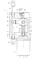
図1は、本発明に係る電動リニアアクチュエータの一実施形態を示す正面断面図、図2は図1のアクチュエータのストッパ部が軸心からずれた位置に設けられた場合の要部断面図である。
Hereinafter, embodiments of the present invention will be described in detail with reference to the drawings.
FIG. 1 is a front cross-sectional view showing an embodiment of an electric linear actuator according to the present invention, and FIG. 2 is a main cross-sectional view when the stopper portion of the actuator in FIG. 1 is provided at a position shifted from the axis. .
この電動リニアアクチュエータ1は、ハウジング2に取り付けられた電動モータ3と、ハウジング2に対して回転自在に、かつ軸方向移動不可に支持されたねじ軸4、およびこのねじ軸4に不図示の多数のボールを介して外挿され、回転不可に、かつ軸方向移動自在に支持されたナット5からなるボールねじ7と、このボールねじ7のねじ軸4と平行に設けられたロッド軸8と、ロッド軸8の略中間部とナット5の外周に互いに反対側に突出する一対の支持軸12とを連結する連結部材9とを備え、電動モータ3の回転運動がボールねじ7を介してロッド軸8の軸方向運動に変換される構成となっている。
The electric
ハウジング2は、電動モータ3が取り付けられるモータ側端壁21と、電動モータ3と反対側の反モータ側端壁22と、モータ側端壁21と反モータ側端壁22を連結する連結壁23と、を備え、ねじ軸4はモータ側端壁21と反モータ側端壁22間に架け渡される構成となっている。
The
ねじ軸4の一方の軸端部4aは、モータ側端壁21に設けられた軸穴21a内で、電動モータ3の主軸3aにセレーション等を介してトルク伝達可能に、かつ軸方向に着脱可能に結合されている。軸穴21aの内径は、ねじ軸4及び主軸3aよりも大径の穴で、ねじ軸4及び主軸3aと干渉しない。また、ねじ軸4の他方の軸端部4bは、ハウジング2の反モータ側端壁22に設けられた軸穴22a内で、転がり軸受10を介して、軸方向移動不可に、かつハウジング2に対して回転自在に支承されている。軸穴22aはねじ軸4よりも大径で、転がり軸受10は、軸穴22aの外側開口部側に形成された軸受穴22bに装着されている。
One
ロッド軸8は、ハウジング2のモータ側端壁21と反モータ側端壁22に形成された挿通穴21c、22cに内挿され、軸受11、11を介して軸方向移動自在に支持されると共に、中間部が連結部材9に固定されている。このロッド軸8の両端部には、プッシュプルケーブル等に接続されるヨークからなる連結部8a、8bが設けられている。
The
ナット5の外周に突出する支持軸12は円柱状で、ナット5の両側に一対設けられるもので、ねじ軸4の軸心に対して180°対称的に直交配置されている。
連結部材9は、ロッド軸8に連結される腕部9aと、ナットの支持軸12に連結される門型形状のナット側連結部9bとを備えた形状となっており、支持軸12がナット側連結部9bの凹部9cに嵌り込んだ状態で連動するようになっている。ロッド軸8とねじ軸4とを含む平面と平行で両軸と直交する方向を高さ方向とすると、支持軸12が、ねじ軸4の軸心と同じ高さにおいてナット側連結部9bの凹部9cの左右内側面と接する構造となっている。
The
The connecting
一方、連結部材9の支持軸12に係合するナット側連結部9bにはストッパ部13が設けられ、異常作動によってオーバーランした時に、ストッパ部13がハウジング2側のモータ側端壁21あるいは反モータ側端壁22の内壁に当接してナット5の軸方向移動を規制する構成となっている。ストッパ部13は、連結部材9のナット側連結部9bの左右側面に、ナット幅より僅かに部分的に突出する凸部によって構成され、ハウジング2のモータ側端壁21及び反モータ側端壁22の内壁に衝突し、ストッパの役目を成す。ストッパ部13が当接するのは、モータ側端壁21及び反モータ側端壁22の各軸穴21a、22aの左右側縁部で、ナット5の支持軸12およびねじ軸4の軸心と同じ高さに設定されている。
On the other hand, a
本実施例では、ハウジング2がアルミ製の鋳物によって構成され、そのままでは、ストッパ部13が当接するモータ側端壁21及び反モータ側端壁22の内壁が鋳肌で、抜き勾配が付いており、ストッパ部13が衝突した際に捻れが生じるおそれがある。この捻れを防止するため、機械加工により勾配部は除去され、ハウジング2のモータ側端壁21及び反モータ側端壁22の内壁を平行面としている。また、連結部材9は熱処理によって表面硬度を高めたものに対し、ハウジング2側がアルミ材と軟材であるため、衝突時の衝撃力が緩和される。
また、連結部材9のストッパ部13はナット5の支持軸12よりも径方向に長いものとし、連結部材9の一端は軸方向移動自在に支持されたロッド軸8と連結された構造とすることで、ハウジング2の内壁にストッパ部13が当接する際、ボールねじ軸芯を支点にして連結部材9に発生する撓みにより、ねじ部がセルフロックすることなく、オーバーラン後の復帰も容易となる。
また、連結部材9は、凸状のストッパ部13を有する凹凸形状のため、機械加工ではコスト高の部品となるが、ロストワックス製法などを採用することで比較的安価に製造することが可能である。
In the present embodiment, the
The
In addition, since the connecting
上記構成の電動リニアアクチュエータにあっては、電動モータ3に通電することにより、例えば、電動モータ3の駆動による主軸3aの正回転によってナット5が図中右方向に直線移動すると、支持軸12に連結される連結部材9が右方向へ直線移動し、この連結部材9の移動に伴ってロッド軸8が右方向に直線移動する。一方、電動モータ3の駆動による主軸3aの逆回転によってナット5が図中左方向に直線移動すると連結部材9が左方向へ直線移動し、この連結部材9の移動に伴ってロッド軸8が左方向に直線移動する。
In the electric linear actuator having the above configuration, when the electric motor 3 is energized, for example, when the
通常作動では、ハウジング2の内部空間の範囲、すなわちモータ側端壁21と反モータ側端壁22の間で干渉無くナット5と連結部材9とロッド軸8は軸方向に往復運動を繰り返すが、異常作動でオーバーランした場合には、ねじ軸4上のナット2の可動範囲で右あるいは左に移動し続けようとするが、連結部材9のナット側連結部9bに設けられたストッパ部13が、モータ側端壁21あるいは反モータ側端壁22の内壁に機械的に衝突し、ロッド軸8の移動を規制することができる。
In normal operation, the
このように連結部材9に凸状のストッパ部13を設けたので、ナット5の移動方向にはストッパ部のスペースが不要で、軸方向のサイズを大きくすることなく、所望するストロークを得ることができる。また、ストッパ部13がねじ軸4の軸心と同じ高さに設けられているので、ストッパ当接時に連結部材9を介してロッド軸8に曲げ荷重が負荷されることがない。
Since the
ここで、比較のために、図2に、ストッパ位置が軸心からずれた位置に設けられた場合の模式図を示している。
図1に対し、図2のストッパ部13′は、連結部材9のナット側連結部9bにおけるロッド軸側の端部であり、ハウジング2のモータ側端壁21及び反モータ側端壁22の軸穴21a、22aの上縁部分がストッパ当接部となる。
このようにストッパ部13′の位置が軸心よりずれている場合は、ストッパ位置で機械的に右移動を止めようとして反力が作用し、ストッパ位置を支点としたモーメント荷重がロッド軸8に負荷されることになる。これに対して、図1に示す例では、連結部材9のストッパ部13をねじ軸4の軸心と同一高さ位置に設けているので、衝突時に、連結部材9はボールねじの推力とストッパ部13における反力の高さが異なることにより生じるモーメントによって曲げられることはないため、連結部材9に連結したロッド軸8へ曲げ荷重が負荷されることはない。
Here, for comparison, FIG. 2 shows a schematic diagram when the stopper position is provided at a position deviated from the axis.
2, the
Thus, when the position of the
一方、図1に示す例において、ストッパ部13がハウジング2のモータ側端壁21及び反モータ側端壁22に衝突した場合、ナット5側から連結部材9に回転力が作用し、連結部材9がナット5の回転方向に撓む。この撓みによって衝撃が緩和される反面、ストッパ部13がハウジング2のモータ側端壁21あるいは反モータ側端壁22に食い込み、ストッパ部13の接触摩擦力が増大し、ストッパ部13においてセルフロックが発生するおそれがある。
図3及び図4は、セルフロックの発生を防止する構成の実施例1の変形例を示している。
図1と比較して説明すると、図1に示す例では、特に図示しないが、ストッパ部13は、ナット5の支持軸12に対して、径方向に同一長さか、短い設定となっている。さらに、ストッパ部13の高さ方向(ロッド軸8とねじ軸4とを含む平面と平行で両軸と直交する方向)の幅は、ねじ軸4の径の半分程度である。
これに対して、図3、図4に示す変形例では、ストッパ部13はナット5の支持軸12よりも径方向に長いものとし、ストッパ部13の軸心からの距離を可及的に大きくとっている。また、ストッパ部13の高さ方向(ロッド軸8とねじ軸4とを含む平面と平行で両軸と直交する方向)の幅は、ねじ軸4の径とほぼ同一幅まで拡大している。
On the other hand, in the example shown in FIG. 1, when the
3 and 4 show a modification of the first embodiment configured to prevent the occurrence of self-locking.
When compared with FIG. 1, in the example shown in FIG. 1, although not particularly illustrated, the
In contrast, in the modification shown in FIGS. 3 and 4, the
このようにすれば、ストッパ部13の接触面Sにおけるねじ軸4の軸芯からの距離は、図4に示すように、四角形状の接触面Sの角部位置が最も長くなり、図1に対して、接触面積についても可及的に大きくできる。したがって、ストッパ部13が衝突した際に、ナット5側から連結部材9に回転力が作用し、図4中、2点鎖線で示すように、連結部材9の腕部9aが撓んでも、ねじ軸4の軸芯からの距離が大きく、また、接触面積も大きいので、ストッパ部13の接触面Sの接触摩擦力の増大を抑えることができ、ストッパ部13のセルフロックの発生を防止することができ、オーバーラン後の復帰も容易である。なお、図4中、接触面Sに記載した、ねじ軸4の軸芯を中心にして同心的に描いた円弧状の矢印は、オーバーラン後の復帰時に作用する摩擦トルクの方向を示している。
また、ストッパ部13の高さ方向の幅が、ねじ軸4の径より大きい場合には、たとえば、ストッパ部13の角部が片当たりした場合、ねじ軸4からナット5に作用する軸方向力と、ストッパ部13からの反力の方向が図2と同様に高さ方向にずれるので、ねじ軸4の径とほぼ同一幅まで拡大することが好ましい。
In this way, the distance from the axial center of the
Further, when the width in the height direction of the
なお、図1の実施例の比較例として、図2のようなストッパ位置がねじ軸の軸心とずれている例を示したが、本発明はこのストッパ部が軸心位置からずれたものを排除するものではなく、図2に示す例についても、連結部材にストッパ部を設けるという点で本願発明概念に含まれる。
また、上記実施例では、ストッパ部13と連結部材9を一体としたが、一体ではなく別部品としてもよい。連結部材9とストッパ部13が一体成形されていれば、部品点数、組立工数が増加することなく、コストアップを避けることができる。また、一体とすることで、ストッパ部の固定部分が無いので、信頼性の高いストッパ構造を実現できる。
As a comparative example of the embodiment of FIG. 1, an example in which the stopper position is shifted from the axis of the screw shaft as shown in FIG. 2 is shown. The example shown in FIG. 2 is not excluded, but is included in the concept of the present invention in that a stopper is provided on the connecting member.
Moreover, in the said Example, although the
以上、本発明の実施の形態について説明を行ったが、本発明はこうした実施の形態に何等限定されるものではなく、あくまで例示であって、本発明の要旨を逸脱しない範囲内において、さらに種々なる形態で実施し得ることは勿論のことであり、本発明の範囲は、特許請求の範囲の記載によって示され、さらに特許請求の範囲に記載の均等の意味、および範囲内のすべての変更を含む。 The embodiment of the present invention has been described above, but the present invention is not limited to such an embodiment, and is merely an example, and various modifications can be made without departing from the scope of the present invention. Of course, the scope of the present invention is indicated by the description of the scope of claims, and further, the equivalent meanings described in the scope of claims and all modifications within the scope of the scope of the present invention are included. Including.
本発明に係る電動リニアアクチュエータは、自動車のパーキングギアにポールを係合させてパーキングロックさせる電動パーキングロック装置等の電動リニアアクチュエータとして適用できる。 The electric linear actuator according to the present invention can be applied as an electric linear actuator such as an electric parking lock device for locking a parking lock by engaging a pawl with a parking gear of an automobile.
1・・・・・・・・・・・・・電動リニアアクチュエータ
2・・・・・・・・・・・・・ハウジング
21・・・・・・・・・・・・モータ側端壁
21a・・・・・・・・・・・軸穴
21c・・・・・・・・・・・挿通穴
22・・・・・・・・・・・・反モータ側端壁
22a・・・・・・・・・・・軸穴
22b・・・・・・・・・・・軸受穴
22c・・・・・・・・・・・挿通穴
23・・・・・・・・・・・・連結壁
3・・・・・・・・・・・・・電動モータ
3a・・・・・・・・・・・・主軸
4・・・・・・・・・・・・・ねじ軸
4a、4b・・・・・・・・・軸端部
5・・・・・・・・・・・・・ナット
7・・・・・・・・・・・・・ボールねじ
8・・・・・・・・・・・・・ロッド軸
8a、8b・・・・・・・・・連結部
9・・・・・・・・・・・・・連結部材
9a・・・・・・・・・・・・腕部
9b・・・・・・・・・・・・ナット側連結部
9c・・・・・・・・・・・・凹部
10・・・・・・・・・・・・転がり軸受
11・・・・・・・・・・・・軸受
12・・・・・・・・・・・・支持軸
13・・・・・・・・・・・・ストッパ部
S・・・・・・・・・・・・・接触面
1 ... Electric
Claims (4)
前記連結部材の支持軸に係合するナット側連結部にストッパ部を設け、このストッパ部は、前記連結部材のナット側連結部のナット幅方向の両端面に、ナット幅より僅かに部分的に突出する凸部によって構成され、該ストッパ部をハウジング側のストッパ当接部に当接させてナットの軸方向移動を規制すると共に、前記支持軸は前記ねじ軸の軸心に対して対称的に直交配置されており、前記ロッド軸とねじ軸とを含む平面と平行で両軸と直交する方向を高さ方向とすると、前記支持軸が前記ねじ軸の軸心と同じ高さにおいて前記連結部材と接する構造で、前記ストッパ部とストッパ当接部との当接位置が前記ねじ軸の軸心と同じ高さに設けられていることを特徴とする電動リニアアクチュエータ。 An electric motor attached to the housing, a screw shaft that is coaxially coupled to the main shaft of the electric motor, is supported so as to be rotatable with respect to the housing and is not movable in the axial direction, and a number of balls on the screw shaft A ball screw made of a nut that is extrapolated through the shaft and is supported so as to be non-rotatable and movable in the axial direction, and is arranged in parallel with the screw shaft and supported so as to be movable in the axial direction with respect to the housing. A rod shaft, and a connecting member that connects a substantially intermediate portion of the rod shaft and a support shaft protruding to the outer periphery of the nut, and the rotational motion of the electric motor is changed to the axial motion of the rod shaft via the nut. In the electric linear actuator to be converted,
A stopper portion is provided on the nut-side connecting portion that engages with the support shaft of the connecting member, and this stopper portion is slightly partially smaller than the nut width on both end surfaces of the nut-side connecting portion of the connecting member in the nut width direction. Consists of projecting convex portions, the stopper portion is brought into contact with the stopper abutting portion on the housing side to restrict the axial movement of the nut, and the support shaft is symmetrical with respect to the axis of the screw shaft The connecting member is disposed at a right angle, and when the height direction is a direction parallel to a plane including the rod axis and the screw axis and perpendicular to both axes, the support shaft is at the same height as the axis of the screw axis. An electric linear actuator characterized in that the contact position between the stopper portion and the stopper contact portion is provided at the same height as the axis of the screw shaft.
Priority Applications (1)
| Application Number | Priority Date | Filing Date | Title |
|---|---|---|---|
| JP2008268309A JP5180023B2 (en) | 2008-04-11 | 2008-10-17 | Electric linear actuator |
Applications Claiming Priority (3)
| Application Number | Priority Date | Filing Date | Title |
|---|---|---|---|
| JP2008103012 | 2008-04-11 | ||
| JP2008103012 | 2008-04-11 | ||
| JP2008268309A JP5180023B2 (en) | 2008-04-11 | 2008-10-17 | Electric linear actuator |
Publications (2)
| Publication Number | Publication Date |
|---|---|
| JP2009270709A JP2009270709A (en) | 2009-11-19 |
| JP5180023B2 true JP5180023B2 (en) | 2013-04-10 |
Family
ID=41437440
Family Applications (1)
| Application Number | Title | Priority Date | Filing Date |
|---|---|---|---|
| JP2008268309A Expired - Fee Related JP5180023B2 (en) | 2008-04-11 | 2008-10-17 | Electric linear actuator |
Country Status (1)
| Country | Link |
|---|---|
| JP (1) | JP5180023B2 (en) |
Families Citing this family (8)
| Publication number | Priority date | Publication date | Assignee | Title |
|---|---|---|---|---|
| JP5397236B2 (en) * | 2010-01-18 | 2014-01-22 | Smc株式会社 | Lead screw mechanism |
| JP5249260B2 (en) * | 2010-02-16 | 2013-07-31 | Ckd株式会社 | Actuator |
| WO2014015209A2 (en) * | 2012-07-19 | 2014-01-23 | Pacific Bearing Company | Motor with integrated coupler |
| DE102013104552A1 (en) * | 2013-05-03 | 2014-11-06 | Getrag Getriebe- Und Zahnradfabrik Hermann Hagenmeyer Gmbh & Cie Kg | Switching arrangement for a motor vehicle transmission |
| EP3546083B1 (en) * | 2016-11-22 | 2021-10-20 | Sankyo Seisakusho Co. | Plate material feeding device |
| EP3467347B1 (en) | 2017-10-03 | 2021-12-01 | Hamilton Sundstrand Corporation | Linear actuator |
| JP7105557B2 (en) * | 2017-11-27 | 2022-07-25 | Ntn株式会社 | electric actuator |
| KR20210006035A (en) * | 2019-07-08 | 2021-01-18 | 현대자동차주식회사 | Shifting actuator for transmission |
Family Cites Families (4)
| Publication number | Priority date | Publication date | Assignee | Title |
|---|---|---|---|---|
| JPH0831541A (en) * | 1994-07-14 | 1996-02-02 | Toshiba Eng & Constr Co Ltd | Multishaft control linear mechanism |
| JP2002206615A (en) * | 2001-01-12 | 2002-07-26 | Fuji Photo Optical Co Ltd | Feed screw device |
| JP4582639B2 (en) * | 2005-02-14 | 2010-11-17 | Ntn株式会社 | Electric linear actuator |
| JP2006322490A (en) * | 2005-05-18 | 2006-11-30 | Honda Motor Co Ltd | Electric parking lock device |
-
2008
- 2008-10-17 JP JP2008268309A patent/JP5180023B2/en not_active Expired - Fee Related
Also Published As
| Publication number | Publication date |
|---|---|
| JP2009270709A (en) | 2009-11-19 |
Similar Documents
| Publication | Publication Date | Title |
|---|---|---|
| JP5180023B2 (en) | Electric linear actuator | |
| JP2010169248A (en) | Disk brake | |
| JP4319597B2 (en) | Motor device and wiper motor | |
| CN103249964B (en) | Output block and Multi-shaft drive device | |
| CN107701681B (en) | Rotary drive comprising a load-dependent brake | |
| US6336373B1 (en) | Rotary electromagnetic actuator | |
| JP4697784B2 (en) | Electric linear actuator | |
| JP2007315512A (en) | Electric linear actuator | |
| JP4109608B2 (en) | Wiper motor | |
| JP2009079653A (en) | Electric actuator | |
| JP5101227B2 (en) | Assembly method of electric linear actuator | |
| JP4514021B2 (en) | Ball screw actuator | |
| JP2007232023A (en) | Motor-driven actuator | |
| JP2009162367A (en) | Actuator | |
| JP4729373B2 (en) | Noise reduction mechanism for automatic transmission with motor actuator | |
| JP2008174190A (en) | Electric actuator for parking lock device | |
| JP4973604B2 (en) | Parking device structure | |
| JP2008175357A (en) | Electric actuator | |
| JP4691516B2 (en) | Electric actuator for parking lock device | |
| JP4513450B2 (en) | Actuator | |
| JP3925270B2 (en) | Motor drive device | |
| JP2008174188A (en) | Electric actuator for parking lock device | |
| JP2008069793A (en) | Electric linear actuator | |
| JP2017137962A (en) | Electric actuator | |
| JP2003209952A (en) | Linear actuator fitted with clutch mechanism |
Legal Events
| Date | Code | Title | Description |
|---|---|---|---|
| A621 | Written request for application examination |
Free format text: JAPANESE INTERMEDIATE CODE: A621 Effective date: 20110921 |
|
| A977 | Report on retrieval |
Free format text: JAPANESE INTERMEDIATE CODE: A971007 Effective date: 20120608 |
|
| A131 | Notification of reasons for refusal |
Free format text: JAPANESE INTERMEDIATE CODE: A131 Effective date: 20120612 |
|
| A521 | Written amendment |
Free format text: JAPANESE INTERMEDIATE CODE: A523 Effective date: 20120807 |
|
| A131 | Notification of reasons for refusal |
Free format text: JAPANESE INTERMEDIATE CODE: A131 Effective date: 20120911 |
|
| A521 | Written amendment |
Free format text: JAPANESE INTERMEDIATE CODE: A523 Effective date: 20121106 |
|
| TRDD | Decision of grant or rejection written | ||
| A01 | Written decision to grant a patent or to grant a registration (utility model) |
Free format text: JAPANESE INTERMEDIATE CODE: A01 Effective date: 20121213 |
|
| A61 | First payment of annual fees (during grant procedure) |
Free format text: JAPANESE INTERMEDIATE CODE: A61 Effective date: 20130110 |
|
| R150 | Certificate of patent or registration of utility model |
Ref document number: 5180023 Country of ref document: JP Free format text: JAPANESE INTERMEDIATE CODE: R150 |
|
| R250 | Receipt of annual fees |
Free format text: JAPANESE INTERMEDIATE CODE: R250 |
|
| R250 | Receipt of annual fees |
Free format text: JAPANESE INTERMEDIATE CODE: R250 |
|
| R250 | Receipt of annual fees |
Free format text: JAPANESE INTERMEDIATE CODE: R250 |
|
| R250 | Receipt of annual fees |
Free format text: JAPANESE INTERMEDIATE CODE: R250 |
|
| LAPS | Cancellation because of no payment of annual fees |