JP5177953B2 - Semiconductor device and display device - Google Patents
Semiconductor device and display device Download PDFInfo
- Publication number
- JP5177953B2 JP5177953B2 JP2006010411A JP2006010411A JP5177953B2 JP 5177953 B2 JP5177953 B2 JP 5177953B2 JP 2006010411 A JP2006010411 A JP 2006010411A JP 2006010411 A JP2006010411 A JP 2006010411A JP 5177953 B2 JP5177953 B2 JP 5177953B2
- Authority
- JP
- Japan
- Prior art keywords
- terminal
- potential
- transistor
- pixel
- signal
- Prior art date
- Legal status (The legal status is an assumption and is not a legal conclusion. Google has not performed a legal analysis and makes no representation as to the accuracy of the status listed.)
- Expired - Fee Related
Links
- 239000004065 semiconductor Substances 0.000 title claims description 80
- 239000003990 capacitor Substances 0.000 claims description 92
- 238000007599 discharging Methods 0.000 claims 1
- 238000000926 separation method Methods 0.000 claims 1
- 230000000295 complement effect Effects 0.000 description 131
- 239000010408 film Substances 0.000 description 129
- 239000010410 layer Substances 0.000 description 106
- 239000000758 substrate Substances 0.000 description 101
- 239000000872 buffer Substances 0.000 description 76
- 239000000463 material Substances 0.000 description 76
- 238000005401 electroluminescence Methods 0.000 description 31
- 239000010936 titanium Substances 0.000 description 31
- 230000006870 function Effects 0.000 description 27
- 238000006243 chemical reaction Methods 0.000 description 23
- 238000000034 method Methods 0.000 description 23
- 238000005070 sampling Methods 0.000 description 23
- 238000012546 transfer Methods 0.000 description 23
- 150000002894 organic compounds Chemical class 0.000 description 22
- 230000002093 peripheral effect Effects 0.000 description 21
- 239000011521 glass Substances 0.000 description 17
- 229910052751 metal Inorganic materials 0.000 description 17
- 239000002184 metal Substances 0.000 description 17
- 239000002585 base Substances 0.000 description 16
- 238000007789 sealing Methods 0.000 description 16
- 230000015572 biosynthetic process Effects 0.000 description 15
- 238000002347 injection Methods 0.000 description 15
- 239000007924 injection Substances 0.000 description 15
- 239000011229 interlayer Substances 0.000 description 15
- 239000012212 insulator Substances 0.000 description 14
- VYPSYNLAJGMNEJ-UHFFFAOYSA-N silicon dioxide Inorganic materials O=[Si]=O VYPSYNLAJGMNEJ-UHFFFAOYSA-N 0.000 description 14
- 229910021417 amorphous silicon Inorganic materials 0.000 description 13
- 239000012535 impurity Substances 0.000 description 11
- 239000010409 thin film Substances 0.000 description 11
- 229910052782 aluminium Inorganic materials 0.000 description 9
- 150000001875 compounds Chemical class 0.000 description 9
- 230000005525 hole transport Effects 0.000 description 9
- 230000002441 reversible effect Effects 0.000 description 9
- XUIMIQQOPSSXEZ-UHFFFAOYSA-N Silicon Chemical compound [Si] XUIMIQQOPSSXEZ-UHFFFAOYSA-N 0.000 description 8
- NRTOMJZYCJJWKI-UHFFFAOYSA-N Titanium nitride Chemical compound [Ti]#N NRTOMJZYCJJWKI-UHFFFAOYSA-N 0.000 description 8
- 238000004519 manufacturing process Methods 0.000 description 8
- 229910021420 polycrystalline silicon Inorganic materials 0.000 description 8
- 229910052710 silicon Inorganic materials 0.000 description 8
- 239000010703 silicon Substances 0.000 description 8
- 229910052814 silicon oxide Inorganic materials 0.000 description 8
- 238000009825 accumulation Methods 0.000 description 7
- 229910045601 alloy Inorganic materials 0.000 description 7
- 239000000956 alloy Substances 0.000 description 7
- 230000007423 decrease Effects 0.000 description 7
- 238000010586 diagram Methods 0.000 description 7
- AMGQUBHHOARCQH-UHFFFAOYSA-N indium;oxotin Chemical compound [In].[Sn]=O AMGQUBHHOARCQH-UHFFFAOYSA-N 0.000 description 7
- 239000000565 sealant Substances 0.000 description 7
- 239000002356 single layer Substances 0.000 description 7
- 239000000919 ceramic Substances 0.000 description 6
- 229910052744 lithium Inorganic materials 0.000 description 6
- 239000011159 matrix material Substances 0.000 description 6
- 239000012788 optical film Substances 0.000 description 6
- BASFCYQUMIYNBI-UHFFFAOYSA-N platinum Substances [Pt] BASFCYQUMIYNBI-UHFFFAOYSA-N 0.000 description 6
- 239000010453 quartz Substances 0.000 description 6
- YVTHLONGBIQYBO-UHFFFAOYSA-N zinc indium(3+) oxygen(2-) Chemical compound [O--].[Zn++].[In+3] YVTHLONGBIQYBO-UHFFFAOYSA-N 0.000 description 6
- 229910017073 AlLi Inorganic materials 0.000 description 5
- PIGFYZPCRLYGLF-UHFFFAOYSA-N Aluminum nitride Chemical compound [Al]#N PIGFYZPCRLYGLF-UHFFFAOYSA-N 0.000 description 5
- 229910017911 MgIn Inorganic materials 0.000 description 5
- 229910004298 SiO 2 Inorganic materials 0.000 description 5
- XAGFODPZIPBFFR-UHFFFAOYSA-N aluminium Chemical compound [Al] XAGFODPZIPBFFR-UHFFFAOYSA-N 0.000 description 5
- 230000008859 change Effects 0.000 description 5
- 230000007547 defect Effects 0.000 description 5
- AHLBNYSZXLDEJQ-FWEHEUNISA-N orlistat Chemical compound CCCCCCCCCCC[C@H](OC(=O)[C@H](CC(C)C)NC=O)C[C@@H]1OC(=O)[C@H]1CCCCCC AHLBNYSZXLDEJQ-FWEHEUNISA-N 0.000 description 5
- 238000012545 processing Methods 0.000 description 5
- 239000003566 sealing material Substances 0.000 description 5
- LIVNPJMFVYWSIS-UHFFFAOYSA-N silicon monoxide Chemical compound [Si-]#[O+] LIVNPJMFVYWSIS-UHFFFAOYSA-N 0.000 description 5
- 230000005236 sound signal Effects 0.000 description 5
- XLOMVQKBTHCTTD-UHFFFAOYSA-N zinc oxide Inorganic materials [Zn]=O XLOMVQKBTHCTTD-UHFFFAOYSA-N 0.000 description 5
- 229910004261 CaF 2 Inorganic materials 0.000 description 4
- 229910052791 calcium Inorganic materials 0.000 description 4
- 239000011575 calcium Substances 0.000 description 4
- 238000012937 correction Methods 0.000 description 4
- 238000002425 crystallisation Methods 0.000 description 4
- 230000002950 deficient Effects 0.000 description 4
- 230000006866 deterioration Effects 0.000 description 4
- 230000009977 dual effect Effects 0.000 description 4
- 238000005286 illumination Methods 0.000 description 4
- 239000004973 liquid crystal related substance Substances 0.000 description 4
- 229910052709 silver Inorganic materials 0.000 description 4
- 239000011701 zinc Substances 0.000 description 4
- UOCMXZLNHQBBOS-UHFFFAOYSA-N 2-(1,3-benzoxazol-2-yl)phenol zinc Chemical compound [Zn].Oc1ccccc1-c1nc2ccccc2o1.Oc1ccccc1-c1nc2ccccc2o1 UOCMXZLNHQBBOS-UHFFFAOYSA-N 0.000 description 3
- 239000004925 Acrylic resin Substances 0.000 description 3
- 229920000178 Acrylic resin Polymers 0.000 description 3
- IJGRMHOSHXDMSA-UHFFFAOYSA-N Atomic nitrogen Chemical compound N#N IJGRMHOSHXDMSA-UHFFFAOYSA-N 0.000 description 3
- UHOVQNZJYSORNB-UHFFFAOYSA-N Benzene Chemical group C1=CC=CC=C1 UHOVQNZJYSORNB-UHFFFAOYSA-N 0.000 description 3
- 229910052581 Si3N4 Inorganic materials 0.000 description 3
- 150000004696 coordination complex Chemical class 0.000 description 3
- 230000003111 delayed effect Effects 0.000 description 3
- 238000005530 etching Methods 0.000 description 3
- 229910052757 nitrogen Inorganic materials 0.000 description 3
- 229920005591 polysilicon Polymers 0.000 description 3
- HQVNEWCFYHHQES-UHFFFAOYSA-N silicon nitride Chemical compound N12[Si]34N5[Si]62N3[Si]51N64 HQVNEWCFYHHQES-UHFFFAOYSA-N 0.000 description 3
- 238000002834 transmittance Methods 0.000 description 3
- IYZMXHQDXZKNCY-UHFFFAOYSA-N 1-n,1-n-diphenyl-4-n,4-n-bis[4-(n-phenylanilino)phenyl]benzene-1,4-diamine Chemical compound C1=CC=CC=C1N(C=1C=CC(=CC=1)N(C=1C=CC(=CC=1)N(C=1C=CC=CC=1)C=1C=CC=CC=1)C=1C=CC(=CC=1)N(C=1C=CC=CC=1)C=1C=CC=CC=1)C1=CC=CC=C1 IYZMXHQDXZKNCY-UHFFFAOYSA-N 0.000 description 2
- DHDHJYNTEFLIHY-UHFFFAOYSA-N 4,7-diphenyl-1,10-phenanthroline Chemical compound C1=CC=CC=C1C1=CC=NC2=C1C=CC1=C(C=3C=CC=CC=3)C=CN=C21 DHDHJYNTEFLIHY-UHFFFAOYSA-N 0.000 description 2
- 241001270131 Agaricus moelleri Species 0.000 description 2
- XKRFYHLGVUSROY-UHFFFAOYSA-N Argon Chemical compound [Ar] XKRFYHLGVUSROY-UHFFFAOYSA-N 0.000 description 2
- OKTJSMMVPCPJKN-UHFFFAOYSA-N Carbon Chemical compound [C] OKTJSMMVPCPJKN-UHFFFAOYSA-N 0.000 description 2
- VYZAMTAEIAYCRO-UHFFFAOYSA-N Chromium Chemical compound [Cr] VYZAMTAEIAYCRO-UHFFFAOYSA-N 0.000 description 2
- OAICVXFJPJFONN-UHFFFAOYSA-N Phosphorus Chemical compound [P] OAICVXFJPJFONN-UHFFFAOYSA-N 0.000 description 2
- 229920001609 Poly(3,4-ethylenedioxythiophene) Polymers 0.000 description 2
- 239000007983 Tris buffer Substances 0.000 description 2
- NIXOWILDQLNWCW-UHFFFAOYSA-N acrylic acid group Chemical group C(C=C)(=O)O NIXOWILDQLNWCW-UHFFFAOYSA-N 0.000 description 2
- UFVXQDWNSAGPHN-UHFFFAOYSA-K bis[(2-methylquinolin-8-yl)oxy]-(4-phenylphenoxy)alumane Chemical compound [Al+3].C1=CC=C([O-])C2=NC(C)=CC=C21.C1=CC=C([O-])C2=NC(C)=CC=C21.C1=CC([O-])=CC=C1C1=CC=CC=C1 UFVXQDWNSAGPHN-UHFFFAOYSA-K 0.000 description 2
- XJHCXCQVJFPJIK-UHFFFAOYSA-M caesium fluoride Chemical compound [F-].[Cs+] XJHCXCQVJFPJIK-UHFFFAOYSA-M 0.000 description 2
- 239000002041 carbon nanotube Substances 0.000 description 2
- 229910021393 carbon nanotube Inorganic materials 0.000 description 2
- 239000011651 chromium Substances 0.000 description 2
- 229910052804 chromium Inorganic materials 0.000 description 2
- 239000013078 crystal Substances 0.000 description 2
- 230000008025 crystallization Effects 0.000 description 2
- 238000001704 evaporation Methods 0.000 description 2
- 239000000284 extract Substances 0.000 description 2
- 239000011152 fibreglass Substances 0.000 description 2
- 239000007850 fluorescent dye Substances 0.000 description 2
- 150000002484 inorganic compounds Chemical class 0.000 description 2
- 229910010272 inorganic material Inorganic materials 0.000 description 2
- PQXKHYXIUOZZFA-UHFFFAOYSA-M lithium fluoride Chemical compound [Li+].[F-] PQXKHYXIUOZZFA-UHFFFAOYSA-M 0.000 description 2
- 229910021421 monocrystalline silicon Inorganic materials 0.000 description 2
- IBHBKWKFFTZAHE-UHFFFAOYSA-N n-[4-[4-(n-naphthalen-1-ylanilino)phenyl]phenyl]-n-phenylnaphthalen-1-amine Chemical group C1=CC=CC=C1N(C=1C2=CC=CC=C2C=CC=1)C1=CC=C(C=2C=CC(=CC=2)N(C=2C=CC=CC=2)C=2C3=CC=CC=C3C=CC=2)C=C1 IBHBKWKFFTZAHE-UHFFFAOYSA-N 0.000 description 2
- 230000003071 parasitic effect Effects 0.000 description 2
- 229910052698 phosphorus Inorganic materials 0.000 description 2
- 239000011574 phosphorus Substances 0.000 description 2
- 239000004033 plastic Substances 0.000 description 2
- 229920003023 plastic Polymers 0.000 description 2
- 229910052697 platinum Inorganic materials 0.000 description 2
- 229920000642 polymer Polymers 0.000 description 2
- 229920002620 polyvinyl fluoride Polymers 0.000 description 2
- -1 porphyrin compounds Chemical class 0.000 description 2
- 230000008569 process Effects 0.000 description 2
- 230000004044 response Effects 0.000 description 2
- 229910021332 silicide Inorganic materials 0.000 description 2
- FVBUAEGBCNSCDD-UHFFFAOYSA-N silicide(4-) Chemical compound [Si-4] FVBUAEGBCNSCDD-UHFFFAOYSA-N 0.000 description 2
- WFKWXMTUELFFGS-UHFFFAOYSA-N tungsten Chemical compound [W] WFKWXMTUELFFGS-UHFFFAOYSA-N 0.000 description 2
- 239000010937 tungsten Substances 0.000 description 2
- 229910052721 tungsten Inorganic materials 0.000 description 2
- 239000011787 zinc oxide Substances 0.000 description 2
- POILWHVDKZOXJZ-ARJAWSKDSA-M (z)-4-oxopent-2-en-2-olate Chemical compound C\C([O-])=C\C(C)=O POILWHVDKZOXJZ-ARJAWSKDSA-M 0.000 description 1
- UHXOHPVVEHBKKT-UHFFFAOYSA-N 1-(2,2-diphenylethenyl)-4-[4-(2,2-diphenylethenyl)phenyl]benzene Chemical group C=1C=C(C=2C=CC(C=C(C=3C=CC=CC=3)C=3C=CC=CC=3)=CC=2)C=CC=1C=C(C=1C=CC=CC=1)C1=CC=CC=C1 UHXOHPVVEHBKKT-UHFFFAOYSA-N 0.000 description 1
- VFMUXPQZKOKPOF-UHFFFAOYSA-N 2,3,7,8,12,13,17,18-octaethyl-21,23-dihydroporphyrin platinum Chemical compound [Pt].CCc1c(CC)c2cc3[nH]c(cc4nc(cc5[nH]c(cc1n2)c(CC)c5CC)c(CC)c4CC)c(CC)c3CC VFMUXPQZKOKPOF-UHFFFAOYSA-N 0.000 description 1
- FQJQNLKWTRGIEB-UHFFFAOYSA-N 2-(4-tert-butylphenyl)-5-[3-[5-(4-tert-butylphenyl)-1,3,4-oxadiazol-2-yl]phenyl]-1,3,4-oxadiazole Chemical compound C1=CC(C(C)(C)C)=CC=C1C1=NN=C(C=2C=C(C=CC=2)C=2OC(=NN=2)C=2C=CC(=CC=2)C(C)(C)C)O1 FQJQNLKWTRGIEB-UHFFFAOYSA-N 0.000 description 1
- YLYPIBBGWLKELC-RMKNXTFCSA-N 2-[2-[(e)-2-[4-(dimethylamino)phenyl]ethenyl]-6-methylpyran-4-ylidene]propanedinitrile Chemical compound C1=CC(N(C)C)=CC=C1\C=C\C1=CC(=C(C#N)C#N)C=C(C)O1 YLYPIBBGWLKELC-RMKNXTFCSA-N 0.000 description 1
- PZLZJGZGJHZQAU-UHFFFAOYSA-N 3-(4-tert-butylphenyl)-4-(4-ethylphenyl)-5-(4-phenylphenyl)-1,2,4-triazole Chemical compound C1=CC(CC)=CC=C1N1C(C=2C=CC(=CC=2)C(C)(C)C)=NN=C1C1=CC=C(C=2C=CC=CC=2)C=C1 PZLZJGZGJHZQAU-UHFFFAOYSA-N 0.000 description 1
- OGGKVJMNFFSDEV-UHFFFAOYSA-N 3-methyl-n-[4-[4-(n-(3-methylphenyl)anilino)phenyl]phenyl]-n-phenylaniline Chemical group CC1=CC=CC(N(C=2C=CC=CC=2)C=2C=CC(=CC=2)C=2C=CC(=CC=2)N(C=2C=CC=CC=2)C=2C=C(C)C=CC=2)=C1 OGGKVJMNFFSDEV-UHFFFAOYSA-N 0.000 description 1
- 229920002799 BoPET Polymers 0.000 description 1
- 241000284156 Clerodendrum quadriloculare Species 0.000 description 1
- 239000004593 Epoxy Substances 0.000 description 1
- WHXSMMKQMYFTQS-UHFFFAOYSA-N Lithium Chemical compound [Li] WHXSMMKQMYFTQS-UHFFFAOYSA-N 0.000 description 1
- 239000005041 Mylar™ Substances 0.000 description 1
- ZCQWOFVYLHDMMC-UHFFFAOYSA-N Oxazole Chemical compound C1=COC=N1 ZCQWOFVYLHDMMC-UHFFFAOYSA-N 0.000 description 1
- 239000004642 Polyimide Substances 0.000 description 1
- 229910052772 Samarium Inorganic materials 0.000 description 1
- FZWLAAWBMGSTSO-UHFFFAOYSA-N Thiazole Chemical compound C1=CSC=N1 FZWLAAWBMGSTSO-UHFFFAOYSA-N 0.000 description 1
- LEVVHYCKPQWKOP-UHFFFAOYSA-N [Si].[Ge] Chemical compound [Si].[Ge] LEVVHYCKPQWKOP-UHFFFAOYSA-N 0.000 description 1
- CUJRVFIICFDLGR-UHFFFAOYSA-N acetylacetonate Chemical compound CC(=O)[CH-]C(C)=O CUJRVFIICFDLGR-UHFFFAOYSA-N 0.000 description 1
- 230000009471 action Effects 0.000 description 1
- 229910052783 alkali metal Inorganic materials 0.000 description 1
- 229910000272 alkali metal oxide Inorganic materials 0.000 description 1
- 150000001340 alkali metals Chemical class 0.000 description 1
- PNEYBMLMFCGWSK-UHFFFAOYSA-N aluminium oxide Inorganic materials [O-2].[O-2].[O-2].[Al+3].[Al+3] PNEYBMLMFCGWSK-UHFFFAOYSA-N 0.000 description 1
- 238000000137 annealing Methods 0.000 description 1
- 229910052786 argon Inorganic materials 0.000 description 1
- 150000004982 aromatic amines Chemical class 0.000 description 1
- QVGXLLKOCUKJST-UHFFFAOYSA-N atomic oxygen Chemical compound [O] QVGXLLKOCUKJST-UHFFFAOYSA-N 0.000 description 1
- WZJYKHNJTSNBHV-UHFFFAOYSA-N benzo[h]quinoline Chemical group C1=CN=C2C3=CC=CC=C3C=CC2=C1 WZJYKHNJTSNBHV-UHFFFAOYSA-N 0.000 description 1
- GQVWHWAWLPCBHB-UHFFFAOYSA-L beryllium;benzo[h]quinolin-10-olate Chemical compound [Be+2].C1=CC=NC2=C3C([O-])=CC=CC3=CC=C21.C1=CC=NC2=C3C([O-])=CC=CC3=CC=C21 GQVWHWAWLPCBHB-UHFFFAOYSA-L 0.000 description 1
- 230000005540 biological transmission Effects 0.000 description 1
- 230000000903 blocking effect Effects 0.000 description 1
- XZCJVWCMJYNSQO-UHFFFAOYSA-N butyl pbd Chemical compound C1=CC(C(C)(C)C)=CC=C1C1=NN=C(C=2C=CC(=CC=2)C=2C=CC=CC=2)O1 XZCJVWCMJYNSQO-UHFFFAOYSA-N 0.000 description 1
- WUKWITHWXAAZEY-UHFFFAOYSA-L calcium difluoride Chemical compound [F-].[F-].[Ca+2] WUKWITHWXAAZEY-UHFFFAOYSA-L 0.000 description 1
- 229910001634 calcium fluoride Inorganic materials 0.000 description 1
- 229910052799 carbon Inorganic materials 0.000 description 1
- 230000001413 cellular effect Effects 0.000 description 1
- 229920001940 conductive polymer Polymers 0.000 description 1
- XCJYREBRNVKWGJ-UHFFFAOYSA-N copper(II) phthalocyanine Chemical compound [Cu+2].C12=CC=CC=C2C(N=C2[N-]C(C3=CC=CC=C32)=N2)=NC1=NC([C]1C=CC=CC1=1)=NC=1N=C1[C]3C=CC=CC3=C2[N-]1 XCJYREBRNVKWGJ-UHFFFAOYSA-N 0.000 description 1
- 238000013461 design Methods 0.000 description 1
- 230000008020 evaporation Effects 0.000 description 1
- 230000005281 excited state Effects 0.000 description 1
- PCHJSUWPFVWCPO-UHFFFAOYSA-N gold Chemical compound [Au] PCHJSUWPFVWCPO-UHFFFAOYSA-N 0.000 description 1
- 229910052737 gold Inorganic materials 0.000 description 1
- 239000010931 gold Substances 0.000 description 1
- RBTKNAXYKSUFRK-UHFFFAOYSA-N heliogen blue Chemical compound [Cu].[N-]1C2=C(C=CC=C3)C3=C1N=C([N-]1)C3=CC=CC=C3C1=NC([N-]1)=C(C=CC=C3)C3=C1N=C([N-]1)C3=CC=CC=C3C1=N2 RBTKNAXYKSUFRK-UHFFFAOYSA-N 0.000 description 1
- 230000006872 improvement Effects 0.000 description 1
- 239000011261 inert gas Substances 0.000 description 1
- 229910052741 iridium Inorganic materials 0.000 description 1
- GKOZUEZYRPOHIO-UHFFFAOYSA-N iridium atom Chemical compound [Ir] GKOZUEZYRPOHIO-UHFFFAOYSA-N 0.000 description 1
- UEEXRMUCXBPYOV-UHFFFAOYSA-N iridium;2-phenylpyridine Chemical compound [Ir].C1=CC=CC=C1C1=CC=CC=N1.C1=CC=CC=C1C1=CC=CC=N1.C1=CC=CC=C1C1=CC=CC=N1 UEEXRMUCXBPYOV-UHFFFAOYSA-N 0.000 description 1
- 238000002955 isolation Methods 0.000 description 1
- 238000005499 laser crystallization Methods 0.000 description 1
- 239000002346 layers by function Substances 0.000 description 1
- 239000003446 ligand Substances 0.000 description 1
- FUJCRWPEOMXPAD-UHFFFAOYSA-N lithium oxide Chemical compound [Li+].[Li+].[O-2] FUJCRWPEOMXPAD-UHFFFAOYSA-N 0.000 description 1
- 229910001947 lithium oxide Inorganic materials 0.000 description 1
- 125000000040 m-tolyl group Chemical group [H]C1=C([H])C(*)=C([H])C(=C1[H])C([H])([H])[H] 0.000 description 1
- 239000012528 membrane Substances 0.000 description 1
- 229910001507 metal halide Inorganic materials 0.000 description 1
- 150000005309 metal halides Chemical class 0.000 description 1
- DCZNSJVFOQPSRV-UHFFFAOYSA-N n,n-diphenyl-4-[4-(n-phenylanilino)phenyl]aniline Chemical group C1=CC=CC=C1N(C=1C=CC(=CC=1)C=1C=CC(=CC=1)N(C=1C=CC=CC=1)C=1C=CC=CC=1)C1=CC=CC=C1 DCZNSJVFOQPSRV-UHFFFAOYSA-N 0.000 description 1
- 150000004866 oxadiazoles Chemical class 0.000 description 1
- TWNQGVIAIRXVLR-UHFFFAOYSA-N oxo(oxoalumanyloxy)alumane Chemical compound O=[Al]O[Al]=O TWNQGVIAIRXVLR-UHFFFAOYSA-N 0.000 description 1
- 239000001301 oxygen Substances 0.000 description 1
- 229910052760 oxygen Inorganic materials 0.000 description 1
- 230000000737 periodic effect Effects 0.000 description 1
- 150000005041 phenanthrolines Chemical class 0.000 description 1
- IEQIEDJGQAUEQZ-UHFFFAOYSA-N phthalocyanine Chemical compound N1C(N=C2C3=CC=CC=C3C(N=C3C4=CC=CC=C4C(=N4)N3)=N2)=C(C=CC=C2)C2=C1N=C1C2=CC=CC=C2C4=N1 IEQIEDJGQAUEQZ-UHFFFAOYSA-N 0.000 description 1
- 229920000172 poly(styrenesulfonic acid) Polymers 0.000 description 1
- 229920000767 polyaniline Polymers 0.000 description 1
- 229920000728 polyester Polymers 0.000 description 1
- 229920001721 polyimide Polymers 0.000 description 1
- 229940005642 polystyrene sulfonic acid Drugs 0.000 description 1
- 230000001681 protective effect Effects 0.000 description 1
- 125000002943 quinolinyl group Chemical group N1=C(C=CC2=CC=CC=C12)* 0.000 description 1
- 230000006798 recombination Effects 0.000 description 1
- 238000005215 recombination Methods 0.000 description 1
- 230000009467 reduction Effects 0.000 description 1
- 239000011347 resin Substances 0.000 description 1
- 229920005989 resin Polymers 0.000 description 1
- 230000000630 rising effect Effects 0.000 description 1
- 238000004904 shortening Methods 0.000 description 1
- 239000000126 substance Substances 0.000 description 1
- 238000007740 vapor deposition Methods 0.000 description 1
- 239000002699 waste material Substances 0.000 description 1
- OYQCBJZGELKKPM-UHFFFAOYSA-N zinc indium(3+) oxygen(2-) Chemical compound [O-2].[Zn+2].[O-2].[In+3] OYQCBJZGELKKPM-UHFFFAOYSA-N 0.000 description 1
- GWDUZCIBPDVBJM-UHFFFAOYSA-L zinc;2-(2-hydroxyphenyl)-3h-1,3-benzothiazole-2-carboxylate Chemical compound [Zn+2].OC1=CC=CC=C1C1(C([O-])=O)SC2=CC=CC=C2N1.OC1=CC=CC=C1C1(C([O-])=O)SC2=CC=CC=C2N1 GWDUZCIBPDVBJM-UHFFFAOYSA-L 0.000 description 1
- QEPMORHSGFRDLW-UHFFFAOYSA-L zinc;2-(2-hydroxyphenyl)-3h-1,3-benzoxazole-2-carboxylate Chemical compound [Zn+2].OC1=CC=CC=C1C1(C([O-])=O)OC2=CC=CC=C2N1.OC1=CC=CC=C1C1(C([O-])=O)OC2=CC=CC=C2N1 QEPMORHSGFRDLW-UHFFFAOYSA-L 0.000 description 1
Images


Classifications
-
- Y02B20/343—
-
- Y02B20/346—
Landscapes
- Electroluminescent Light Sources (AREA)
- Control Of Indicators Other Than Cathode Ray Tubes (AREA)
- Control Of El Displays (AREA)
Description
本発明は負荷に供給する電流をトランジスタで制御する機能を設けた半導体装置に係り、特に電流によって輝度が変化する電流駆動型発光素子で形成された画素や、その信号線駆動回路を含む表示装置に関する。また、その駆動方法に関する。また、その表示装置を表示部に有する電子機器に関する。 The present invention relates to a semiconductor device having a function of controlling a current supplied to a load by a transistor, and in particular, a display device including a pixel formed of a current-driven light-emitting element whose luminance changes depending on the current, and a signal line driving circuit thereof. About. Further, the present invention relates to the driving method. The present invention also relates to an electronic device having the display device in a display portion.
近年、画素を発光ダイオード(LED)などの発光素子で形成した、いわゆる自発光型の表示装置が注目を浴びている。このような自発光型の表示装置に用いられる発光素子としては、有機発光ダイオード(OLED(Organic Light Emitting Diode))、有機EL素子、エレクトロルミネッセンス(Electro Luminescence:EL)素子などが注目を集めており、ELディスプレイなどに用いられるようになってきている。OLEDなどの発光素子は自発光型であるため、液晶ディスプレイに比べて画素の視認性が高く、バックライトが不要で応答速度が速い等の利点がある。なお、発光素子の輝度は、そこを流れる電流値によって制御される。 In recent years, so-called self-luminous display devices in which pixels are formed by light-emitting elements such as light-emitting diodes (LEDs) have attracted attention. Organic light emitting diodes (OLEDs (Organic Light Emitting Diodes)), organic EL elements, electroluminescence (EL) elements, etc. are attracting attention as light emitting elements used in such self-luminous display devices. It has been used for EL displays and the like. Since light-emitting elements such as OLEDs are self-luminous, there are advantages such as higher pixel visibility than a liquid crystal display, no need for a backlight, and high response speed. Note that the luminance of the light emitting element is controlled by the value of current flowing therethrough.
このような表示装置の階調を表現する駆動方式として、デジタル方式とアナログ方式がある。デジタル方式はデジタル制御で発光素子をオンオフさせ、階調を表現している。デジタル方式の場合、発光・非発光の2状態しかないため、このままでは、2階調しか表現できない。そこで、別の手法を組み合わせて、多階調化を図ることが行われている。多階調化のための手法としては、時間階調法を用いられることが多い。デジタル時間階調方式は、画素毎の輝度の均一性に優れる反面、周波数を高くする必要があり、消費電力が大きくなってしまう。一方、アナログ方式には、発光素子の発光強度をアナログ制御する方式と発光素子の発光時間をアナログ制御する方式がある。発光強度をアナログ制御する方式は、画素毎の薄膜トランジスタ(以下TFTともいう)の特性のバラツキの影響を受けやすく、画素毎の発光にもバラツキが生じてしまう。これに対して、発光時間をアナログ制御し、画素毎の発光の均一性に優れるアナログ時間階調方式の表示装置が非特許文献1に記載されている(非特許文献1参照)。
There are a digital method and an analog method as driving methods for expressing the gradation of such a display device. In the digital method, the light emitting element is turned on / off by digital control to express gradation. In the digital system, there are only two states of light emission and non-light emission, so that only two gradations can be expressed as it is. In view of this, multi-gradation is being achieved by combining different methods. In many cases, a time gray scale method is used as a technique for multi-gradation. The digital time gray scale method is excellent in the uniformity of luminance for each pixel, but requires a high frequency, resulting in an increase in power consumption. On the other hand, the analog method includes a method of analog control of the light emission intensity of the light emitting element and a method of analog control of the light emission time of the light emitting element. The method of analog control of the light emission intensity is easily affected by variations in characteristics of thin film transistors (hereinafter also referred to as TFTs) for each pixel, and also causes variations in light emission for each pixel. On the other hand, Non-Patent
非特許文献1に記載の表示装置の画素は、発光素子と発光素子を駆動するトランジスタとによりインバータを構成している。駆動トランジスタのゲート端子がインバータの入力端子となり、駆動トランジスタのドレイン端子がインバータの出力端子となる。そして、インバータの出力を、発光素子の陽極に入力する。画素に映像信号電圧を書き込む際には、インバータをオンとオフの中間に設定する。そして、発光期間には画素に三角波電圧を入力することでインバータの出力を制御する。つまり、発光素子の陽極に入力される電位となるインバータの出力を制御することで、発光素子の発光・非発光を制御している。
ここで、抵抗負荷型インバータを図10(b)に示し、その抵抗負荷型インバータ伝達特性を図10(a)に示す。図10(a)の横軸は抵抗負荷型インバータの入力端子への入力電位Vinを示し、縦軸は抵抗負荷型インバータの出力端子からの出力電位Voutを示している。抵抗負荷型インバータはトランジスタと抵抗素子から構成され、トランジスタのソース端子には高電源電位Vddが入力され、ドレイン端子には抵抗素子の一方の端子が接続されている。また抵抗素子の他方の端子に低電源電位Vssが入力されている。なお、ここではVss=0Vとする。トランジスタのゲート端子が抵抗負荷型インバータの入力端子となり、トランジスタのドレイン端子が抵抗負荷型インバータの出力端子となる。 Here, the resistance load type inverter is shown in FIG. 10B, and the resistance load type inverter transfer characteristic is shown in FIG. The horizontal axis of FIG. 10A shows the input potential Vin to the input terminal of the resistance load type inverter, and the vertical axis shows the output potential Vout from the output terminal of the resistance load type inverter. The resistance load type inverter includes a transistor and a resistance element. A high power supply potential Vdd is input to a source terminal of the transistor, and one terminal of the resistance element is connected to a drain terminal. The low power supply potential Vss is input to the other terminal of the resistance element. Here, Vss = 0V. The gate terminal of the transistor becomes the input terminal of the resistance load type inverter, and the drain terminal of the transistor becomes the output terminal of the resistance load type inverter.
図10(a)に示す曲線1002はある抵抗負荷型インバータのインバータ伝達特性を示し、曲線1001は抵抗負荷型インバータを構成するトランジスタの電流供給能力が高い場合の抵抗負荷型インバータ伝達特性を示し、曲線1003はトランジスタの電流供給能力が低い場合の抵抗負荷型インバータ伝達特性を示している。
A
つまり、入力電位が十分に高くトランジスタがオフしているときには、抵抗負荷型インバータの出力端子の電位は0Vの電位となり、トランジスタが十分にオンしているときには、抵抗負荷型インバータの出力端子の電位はVddとなる。 That is, when the input potential is sufficiently high and the transistor is turned off, the potential of the output terminal of the resistance load type inverter is 0 V, and when the transistor is sufficiently on, the potential of the output terminal of the resistance load type inverter. Becomes Vdd.
ここで、抵抗負荷型インバータの出力Voutは、電源電位Vddと抵抗素子の抵抗Rとトランジスタのソースドレイン間電流Idを用いて以下の[数1]の式で表される。 Here, the output Vout of the resistive load type inverter is expressed by the following [Equation 1] using the power supply potential Vdd, the resistance R of the resistance element, and the source-drain current Id of the transistor.

また、トランジスタのソースドレイン間電流Idは、飽和領域での動作のときは、次の[数2]の式で示される。なお、μはトランジスタのキャリア移動度を、Coxはゲート絶縁膜の容量を、W/Lはトランジスタのチャネル幅Wとチャネル長Lの比を、Vthはトランジスタのしきい値電圧を示す。 Further, the source-drain current Id of the transistor is expressed by the following [Equation 2] when operating in the saturation region. Note that μ is the carrier mobility of the transistor, Cox is the capacitance of the gate insulating film, W / L is the ratio of the channel width W to the channel length L of the transistor, and Vth is the threshold voltage of the transistor.
よって、トランジスタの電流供給能力はμ、Cox、W/L、Vthなどの大きさによって異なってくる。したがって、トランジスタのこれらの値のバラツキによって抵抗負荷型インバータ伝達特性が異なってしまう。 Therefore, the current supply capability of the transistor varies depending on the magnitude of μ, Cox, W / L, Vth, and the like. Therefore, the resistance load type inverter transfer characteristics differ depending on the variation of these values of the transistors.
このような抵抗負荷型インバータ伝達特性のバラツキは、抵抗素子として発光素子を用いた場合にも同様に生じる。すると、非特許文献1に記載された画素を有する表示装置においても、曲線1001や曲線1002や曲線1003のような抵抗負荷型インバータ伝達特性の画素が存在することとなる。すると、トランジスタが飽和領域でオンしてからトランジスタがオフし、抵抗負荷型インバータの出力電位がVxとなるまでの時間はもちろんのこと、入力端子と出力端子が導通され、オフセットキャンセルされたそれぞれの抵抗負荷型インバータの入力電位Vinv1、Vinv2、Vinv3から抵抗負荷型インバータの出力電位がVxとなるそれぞれの入力電位Va1、Va2、Va3までの時間も抵抗負荷型インバータの伝達特性の異なる画素毎でばらつくこととなる。
Such variations in the resistance load type inverter transfer characteristics occur in the same way even when a light emitting element is used as a resistance element. Then, even in a display device having pixels described in Non-Patent
したがって、アナログの時間で階調を表現する駆動方式の表示装置において、同じ階調の表示であっても画素間で異なってしまい、きれいな表示ができなくなってしまう。 Therefore, in a display device of a driving system that expresses gradations in analog time, even if the display has the same gradation, it differs between pixels, making it impossible to display beautifully.
また、従来の構成では画素中のトランジスタや配線の数が多くなってしまい、開口率が低くなってしまうなどの問題がある。開口率の高い画素と開口率の低い画素で同様の光度を得る場合、開口率の低い画素は、開口率が高い画素に比べて発光素子の輝度を高くする必要がある。よって、開口率の低い画素は、発光素子の劣化の進行が早くなってしまう。また、輝度を高くするため消費電力も高くなってしまう。 Further, the conventional configuration has a problem that the number of transistors and wirings in the pixel increases, resulting in a low aperture ratio. In the case where a pixel with a high aperture ratio and a pixel with a low aperture ratio have the same luminous intensity, the pixel with a low aperture ratio needs to have higher luminance of the light-emitting element than the pixel with a high aperture ratio. Therefore, the deterioration of the light emitting element is accelerated in the pixel having a low aperture ratio. Further, since the luminance is increased, the power consumption is also increased.
また、画素中のトランジスタや配線の数が多くなると、歩留まりも低くなりやすく、表示パネルのコストも高くなってしまう。 In addition, when the number of transistors and wirings in a pixel increases, the yield tends to decrease and the cost of the display panel increases.
そこで、トランジスタの特性バラツキに起因する抵抗負荷型インバータ伝達特性がばらついても、それらの影響を抑制し、きれいに階調を表示することができるアナログ時間階調方式の表示装置を提供することを本発明の課題とする。さらに、開口率の高い画素を有する表示装置を提供し、発光素子の信頼性の向上や、表示パネルのコスト増加を抑制した表示装置を提供することを課題とする。 Therefore, the present invention provides an analog time gray scale display device capable of suppressing gray scale display even if resistance transfer type inverter transfer characteristics due to transistor characteristic variations vary and displaying gray scales clearly. It is an object of the invention. It is another object of the present invention to provide a display device having a pixel with a high aperture ratio, and to provide a display device in which the reliability of a light-emitting element is improved and the cost of a display panel is suppressed.
また、それらの表示装置を表示部に有する電子機器を提供することを課題とする。 It is another object of the present invention to provide an electronic device having such a display device in a display portion.
本発明は、相補的にオンオフするNチャネル型トランジスタとPチャネル型トランジスタで構成されるCMOSインバータを画素に適用し、CMOSインバータの片方の電源電位として他の行の画素の選択を制御する信号の電位を用いるものである。 The present invention applies a CMOS inverter composed of an N-channel transistor and a P-channel transistor that are complementarily turned on / off to a pixel, and uses a signal for controlling selection of pixels in another row as one power supply potential of the CMOS inverter. A potential is used.
本発明の半導体装置は、
ゲート端子、ソース端子、ドレイン端子を有する第1のトランジスタと、
ゲート端子、ソース端子、ドレイン端子を有する第2のトランジスタと、
ゲート端子、ソース端子、ドレイン端子を有する第3のトランジスタと、
第1の電極と第2の電極を有する容量素子と、
を有し、
該第1のトランジスタのゲート端子は第1の走査線に接続され、
該第2のトランジスタのソース端子又はドレイン端子の一方は電源線に接続され、
該第3のトランジスタのソース端子又はドレイン端子の一方は第2の走査線に接続され、
該容量素子の第1の電極が該第2のトランジスタのゲート端子および該第3のトランジスタのゲート端子に接続され、該容量素子の第2の電極が信号線に接続され、
該第2のトランジスタのソース端子又はドレイン端子の他方および該第3のトランジスタのソース端子又はドレイン端子の他方が画素電極に接続され、
該第1のトランジスタのソース端子又はドレイン端子の一方が、該第2のトランジスタのソース端子又はドレイン端子の他方および該第3のトランジスタのソース端子又はドレイン端子の他方に接続され、
該第1のトランジスタのソース端子又はドレイン端子の他方が、該第2のトランジスタのゲート端子および該第3のトランジスタのゲート端子に接続されている。
The semiconductor device of the present invention is
A first transistor having a gate terminal, a source terminal, and a drain terminal;
A second transistor having a gate terminal, a source terminal, and a drain terminal;
A third transistor having a gate terminal, a source terminal, and a drain terminal;
A capacitive element having a first electrode and a second electrode;
Have
The gate terminal of the first transistor is connected to a first scan line;
One of a source terminal or a drain terminal of the second transistor is connected to a power supply line;
One of a source terminal or a drain terminal of the third transistor is connected to a second scan line;
A first electrode of the capacitor is connected to a gate terminal of the second transistor and a gate terminal of the third transistor; a second electrode of the capacitor is connected to a signal line;
The other of the source terminal or the drain terminal of the second transistor and the other of the source terminal or the drain terminal of the third transistor are connected to the pixel electrode;
One of the source terminal or the drain terminal of the first transistor is connected to the other of the source terminal or the drain terminal of the second transistor and the other of the source terminal or the drain terminal of the third transistor;
The other of the source terminal and the drain terminal of the first transistor is connected to the gate terminal of the second transistor and the gate terminal of the third transistor.
また、本発明の半導体装置は、上記構成において、該第1のトランジスタおよび該第3のトランジスタはNチャネル型トランジスタであり、該第2のトランジスタはPチャネル型トランジスタである。 In the semiconductor device of the present invention having the above structure, the first transistor and the third transistor are N-channel transistors, and the second transistor is a P-channel transistor.
本発明の表示装置は、複数の画素がマトリクス状に配置され、
前記複数の画素の少なくとも1つは、Pチャネル型トランジスタ及びNチャネル型トランジスタからなるCMOSインバータと、
該CMOSインバータの入力端子と出力端子との間に接続されたスイッチと、
アナログの電位が入力される信号線と、
該CMOSインバータの入力端子と該信号線との電位差を保持する容量素子と、
該CMOSインバータの出力により発光又は非発光が制御される発光素子と、
をそれぞれ備える複数の画素がマトリクスに配置され、
該CMOSインバータの片方の電源電位として、前記画素のうち他の少なくとも1つの画素のスイッチのオンオフを制御するための信号の電位が用いられる。
In the display device of the present invention, a plurality of pixels are arranged in a matrix,
At least one of the plurality of pixels includes a CMOS inverter including a P-channel transistor and an N-channel transistor;
A switch connected between an input terminal and an output terminal of the CMOS inverter;
A signal line to which an analog potential is input;
A capacitive element that holds a potential difference between the input terminal of the CMOS inverter and the signal line;
A light emitting element in which light emission or non-light emission is controlled by an output of the CMOS inverter;
Are arranged in a matrix,
A potential of a signal for controlling on / off of a switch of at least one other pixel of the pixels is used as one power supply potential of the CMOS inverter.
本発明の他の構成の表示装置は、上記構成において、該スイッチにNチャネル型トランジスタを用いている。 In a display device having another structure of the present invention, an N-channel transistor is used for the switch in the above structure.
本発明の他の構成の表示装置は、上記構成において、該スイッチにPチャネル型トランジスタを用いている。 In a display device having another structure of the present invention, a P-channel transistor is used for the switch in the above structure.
本発明の表示装置は、
ゲート端子、ソース端子、ドレイン端子を有する第1のトランジスタと、
ゲート端子、ソース端子、ドレイン端子を有する第2のトランジスタと、
ゲート端子、ソース端子、ドレイン端子を有する第3のトランジスタと、
第1の電極と第2の電極を有する容量素子と、
画素電極を有する発光素子と、
を有し、
該第1のトランジスタのゲート端子は第1の走査線に接続され、
該第2のトランジスタのソース端子又はドレイン端子の一方は電源線に接続され、
該第3のトランジスタのソース端子又はドレイン端子の一方は第2の走査線に接続され、
該容量素子の第1の電極が該第2のトランジスタのゲート端子および該第3のトランジスタのゲート端子に接続され、該容量素子の第2の電極が信号線に接続され、
該発光素子の画素電極が該第2のトランジスタのソース端子又はドレイン端子の他方および該第3のトランジスタのソース端子又はドレイン端子の他方に接続され、
該第1のトランジスタのソース端子又はドレイン端子の一方が、該第2のトランジスタのソース端子又はドレイン端子の他方および該第3のトランジスタのソース端子又はドレイン端子の他方に接続され、
該第1のトランジスタのソース端子又はドレイン端子の他方が、該第2のトランジスタのゲート端子および該第3のトランジスタのゲート端子に接続されている。
The display device of the present invention includes:
A first transistor having a gate terminal, a source terminal, and a drain terminal;
A second transistor having a gate terminal, a source terminal, and a drain terminal;
A third transistor having a gate terminal, a source terminal, and a drain terminal;
A capacitive element having a first electrode and a second electrode;
A light emitting device having a pixel electrode;
Have
The gate terminal of the first transistor is connected to a first scan line;
One of a source terminal or a drain terminal of the second transistor is connected to a power supply line;
One of a source terminal or a drain terminal of the third transistor is connected to a second scan line;
A first electrode of the capacitor is connected to a gate terminal of the second transistor and a gate terminal of the third transistor; a second electrode of the capacitor is connected to a signal line;
A pixel electrode of the light emitting element is connected to the other of the source terminal or the drain terminal of the second transistor and the other of the source terminal or the drain terminal of the third transistor;
One of the source terminal or the drain terminal of the first transistor is connected to the other of the source terminal or the drain terminal of the second transistor and the other of the source terminal or the drain terminal of the third transistor;
The other of the source terminal and the drain terminal of the first transistor is connected to the gate terminal of the second transistor and the gate terminal of the third transistor.
また、本発明の表示装置は、上記構成において、該第1のトランジスタおよび該第3のトランジスタはNチャネル型トランジスタであり、該第2のトランジスタはPチャネル型トランジスタである。 In the display device of the invention having the above structure, the first transistor and the third transistor are N-channel transistors, and the second transistor is a P-channel transistor.
なお、明細書に示すスイッチは、様々な形態のものを用いることができ、一例として、電気的スイッチや機械的なスイッチなどがある。つまり、電流の流れを制御できるものであればよく、特定のものに限定されず、様々なものを用いることができる。例えば、トランジスタでもよいし、ダイオード(PNダイオード、PINダイオード、ショットキーダイオード、ダイオード接続のトランジスタなど)でもよいし、それらを組み合わせた論理回路でもよい。よって、スイッチとしてトランジスタを用いる場合、そのトランジスタは、単なるスイッチとして動作するため、トランジスタの極性(導電型)は特に限定されない。ただし、オフ電流が少ない方が望ましい場合、オフ電流が少ない方の極性のトランジスタを用いることが望ましい。オフ電流が少ないトランジスタとしては、LDD領域を設けているものやマルチゲート構造にしているもの等がある。また、スイッチとして動作させるトランジスタのソース端子の電位が、低電位側電源(Vss、GND、0Vなど)に近い状態で動作する場合はNチャネル型を、反対に、ソース端子の電位が、高電位側電源(Vddなど)に近い状態で動作する場合はPチャネル型を用いることが望ましい。なぜなら、ゲートソース間電圧の絶対値を大きくできるため、スイッチとして、動作しやすいからである。なお、Nチャネル型とPチャネル型の両方を用いて、CMOS型のスイッチにしてもよい。CMOS型のスイッチにすると、スイッチを介して出力する電圧(つまり入力電圧)が、出力電圧に対して、高かったり、低かったりして、状況が変化する場合においても、適切に動作を行うことが出来る。 Note that a variety of switches can be used as a switch described in the specification, and examples thereof include an electrical switch and a mechanical switch. In other words, any device can be used as long as it can control the flow of current, and it is not limited to a specific device, and various devices can be used. For example, a transistor, a diode (a PN diode, a PIN diode, a Schottky diode, a diode-connected transistor, or the like), or a logic circuit that is a combination thereof may be used. Therefore, when a transistor is used as a switch, the transistor operates as a mere switch, and thus the polarity (conductivity type) of the transistor is not particularly limited. However, when it is desirable that the off-state current is small, it is desirable to use a transistor having a polarity with a small off-state current. As a transistor with low off-state current, there are a transistor provided with an LDD region and a transistor having a multi-gate structure. Further, when the transistor operated as a switch operates at a source terminal potential close to a low potential power source (Vss, GND, 0 V, etc.), the N-channel type is used. On the contrary, the source terminal potential is a high potential. When operating in a state close to the side power supply (Vdd or the like), it is desirable to use a P-channel type. This is because the absolute value of the voltage between the gate and the source can be increased, so that it can easily operate as a switch. Note that both N-channel and P-channel switches may be used as CMOS switches. When a CMOS type switch is used, even if the voltage (ie, input voltage) output through the switch is higher or lower than the output voltage and the situation changes, it can operate properly. I can do it.
なお、本発明において接続されているとは、電気的に接続されていることと同義である。したがって、間に別の素子やスイッチなどが配置されていてもよい。 In the present invention, being connected is synonymous with being electrically connected. Therefore, another element, a switch, or the like may be disposed between them.
なお、発光素子は、様々な形態を用いることが出来る。例えば、EL素子(有機EL素子、無機EL素子又は有機物及び無機物を含むEL素子)、電子放出素子、液晶素子、電子インク、グレーティングライトバルブ(GLV)、プラズマディスプレイ(PDP)、デジタルマイクロミラーデバイス(DMD)、圧電セラミックディスプレイ、カーボンナノチューブ、など、電気磁気的作用によりコントラストが変化する表示媒体を適用することができる。なお、EL素子を用いた表示装置としてはELディスプレイ、電子放出素子を用いた表示装置としてはフィールドエミッションディスプレイ(FED)やSED方式平面型ディスプレイ(SED:Surface−conduction Electron−emitter Disply)など、液晶素子を用いた表示装置としては液晶ディスプレイ、電子インクを用いた表示装置としては電子ペーパーがある。 Note that various forms of light-emitting elements can be used. For example, EL elements (organic EL elements, inorganic EL elements or EL elements including organic and inorganic substances), electron-emitting elements, liquid crystal elements, electronic ink, grating light valves (GLV), plasma displays (PDP), digital micromirror devices ( DMD), piezoelectric ceramic displays, carbon nanotubes, and the like, which can be applied to display media whose contrast is changed by an electromagnetic action. Note that a display device using an EL element is an EL display, and a display device using an electron-emitting device is a liquid crystal display such as a field emission display (FED) or a SED type flat display (SED: Surface-conduction Electron-Emitter Display). There is a liquid crystal display as a display device using an element, and an electronic paper as a display device using electronic ink.
本発明において、適用可能なトランジスタの種類に限定はなく、非晶質シリコンや多結晶シリコンに代表される非単結晶半導体膜を用いた薄膜トランジスタ(TFT)、半導体基板やSOI基板を用いて形成されるMOS型トランジスタ、接合型トランジスタ、バイポーラトランジスタ、有機半導体やカーボンナノチューブを用いたトランジスタ、その他のトランジスタを適用することができる。また、トランジスタが配置されている基板の種類に限定はなく、単結晶基板、SOI基板、ガラス基板、プラスチック基板などにトランジスタを配置することが出来る。 In the present invention, there are no limitations on the types of transistors that can be used, and the transistor is formed using a thin film transistor (TFT) using a non-single-crystal semiconductor film typified by amorphous silicon or polycrystalline silicon, a semiconductor substrate, or an SOI substrate. A MOS transistor, a junction transistor, a bipolar transistor, a transistor using an organic semiconductor or a carbon nanotube, and other transistors can be used. There is no limitation on the kind of the substrate on which the transistor is provided, and the transistor can be provided on a single crystal substrate, an SOI substrate, a glass substrate, a plastic substrate, or the like.
本明細書においては、一画素とは色要素の一要素の画素を示すものとする。よって、R(赤)G(緑)B(青)の色要素からなるフルカラー表示装置の場合には、一画素とはRの色要素の画素やGの色要素の画素やBの色要素の画素のいずれか一をいうものとする。 In the present specification, one pixel means one element of a color element. Therefore, in the case of a full-color display device composed of R (red), G (green), and B (blue) color elements, one pixel is a pixel of an R color element, a pixel of a G color element, or a B color element. It shall mean any one of the pixels.
なお、本明細書において、画素がマトリクスに配置されているとは、縦縞と横縞を組み合わせたいわゆる格子状に配列されているストライプ配置の場合はもちろんのこと、三色の色要素(例えばRGB)でフルカラー表示を行う場合に、1つの画像の最小要素を表す三つの色要素の画素がいわゆるデルタ配置されている場合も含むものとする。 In the present specification, the pixels are arranged in a matrix, not only in the case of a stripe arrangement in which a vertical stripe and a horizontal stripe are combined, but also in a three-color color element (for example, RGB). In the case of performing full color display, the case where pixels of three color elements representing the minimum element of one image are arranged in a so-called delta arrangement is included.
なお、本明細書において、半導体装置とは半導体素子(トランジスタやダイオードなど)を含む回路を有する装置をいう。 Note that in this specification, a semiconductor device refers to a device having a circuit including a semiconductor element (such as a transistor or a diode).
なお、本明細書において発光素子の陽極及び陰極とは、発光素子に順方向電圧を印加したときの電極をいうものとする。 Note that in this specification, an anode and a cathode of a light-emitting element refer to electrodes when a forward voltage is applied to the light-emitting element.
画素内のインバータを構成するトランジスタの特性が画素毎にばらついても、それらの影響を低減し、きれいに階調を表示することができる表示装置を提供することができる。 Even if the characteristics of the transistors that constitute the inverter in the pixel vary from pixel to pixel, it is possible to provide a display device that can reduce the influence of the transistor and display grayscales clearly.
また、画素の開口率を高くし、発光素子の劣化の進行を抑え、信頼性の向上を図ることができる。また、歩留まりが向上し、コストの抑制を図ることができる。 In addition, the aperture ratio of the pixel can be increased, the progress of deterioration of the light-emitting element can be suppressed, and reliability can be improved. Further, the yield can be improved and the cost can be suppressed.
以下、本発明の実施の形態について図面を参照しながら説明する。但し、本発明は多くの異なる態様で実施することが可能であり、本発明の趣旨及びその範囲から逸脱することなくその形態及び詳細を様々に変更し得ることは当業者であれば容易に理解される。従って、本実施の形態の記載内容に限定して解釈されるものではない。 Hereinafter, embodiments of the present invention will be described with reference to the drawings. However, the present invention can be implemented in many different modes, and those skilled in the art can easily understand that the modes and details can be variously changed without departing from the spirit and scope of the present invention. Is done. Therefore, the present invention is not construed as being limited to the description of this embodiment mode.
(実施の形態1)
本実施の形態では本発明の表示装置の画素構成とその動作原理について説明する。
(Embodiment 1)
In this embodiment mode, a pixel structure and an operation principle of a display device of the present invention will be described.
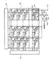
まず、図1を用いて本発明の表示装置の画素構成について詳細に説明する。ここでは、列方向に並んで配置された二画素のみを図示しているが、表示装置の画素部は実際には行方向と列方向にマトリクスに複数の画素が配置されている。 First, the pixel configuration of the display device of the present invention will be described in detail with reference to FIG. Here, only two pixels arranged side by side in the column direction are illustrated, but in the pixel portion of the display device, a plurality of pixels are actually arranged in a matrix in the row direction and the column direction.
画素は、駆動トランジスタ(第2のトランジスタ)101と、相補用トランジスタ(第3のトランジスタ)102と、容量素子103と、スイッチング用トランジスタ(第1のトランジスタ)104と、発光素子105と、走査線(Select line)106と、信号線(Data line)107と、電源線108とを有している。なお、駆動トランジスタ101にはPチャネル型トランジスタ、相補用トランジスタ102及びスイッチング用トランジスタ104にはNチャネル型トランジスタを用いている。
The pixel includes a driving transistor (second transistor) 101, a complementary transistor (third transistor) 102, a
駆動トランジスタ101は、第1端子(ソース端子又はドレイン端子の一方)が電源線108と接続され、第2端子(ソース端子又はドレイン端子の他方)が相補用トランジスタ102の第2端子(ソース端子又はドレイン端子の他方)と接続され、ゲート端子が相補用トランジスタ102のゲート端子と接続されている。さらに、駆動トランジスタ101及び相補用トランジスタ102のゲート端子は、容量素子103を介して信号線107に接続されると共に、スイッチング用トランジスタ104を介して駆動トランジスタ101及び相補用トランジスタ102の第2端子(ソース端子又はドレイン端子の他方)と接続されている。つまり、スイッチング用トランジスタ104は、第1端子(ソース端子又はドレイン端子の一方)が駆動トランジスタ101及び相補用トランジスタ102の第2端子(ソース端子又はドレイン端子の他方)と接続され、第2端子(ソース端子又はドレイン端子の他方)が駆動トランジスタ101及び相補用トランジスタ102のゲート端子と接続されているため、スイッチング用トランジスタ104をオンオフすることで、駆動トランジスタ101及び相補用トランジスタ102のゲート端子と第2端子(ソース端子又はドレイン端子の他方)とを導通又は非導通にすることができる。そして、スイッチング用トランジスタ104のゲート端子が接続されている走査線106に信号を入力することによりスイッチング用トランジスタ104のオンオフを制御する。また、駆動トランジスタ101及び相補用トランジスタ102の第2端子(ソース端子又はドレイン端子の他方)は、発光素子105の陽極と接続されている。そして、発光素子105の陰極は低電源電位Vssが供給された配線(Cathode)109と接続されている。なお、Vssとは、電源線108に供給される電源電位Vddを基準として、Vss<Vddを満たす電位である。例えば、Vss=GND(グラウンド電位)としても良い。
The driving
さらに、相補用トランジスタ102の第1端子(ソース端子又はドレイン端子の一方)は別の行の画素の走査線106Aに接続されている。ここで、駆動トランジスタ101は発光素子105を駆動するトランジスタであり、相補用トランジスタ102は駆動トランジスタ101とは極性が反転しているトランジスタである。つまり、この走査線106Aの信号がLレベルのときに駆動トランジスタ101と相補用トランジスタ102とが相補的にオンオフするインバータを構成している。
Further, the first terminal (one of the source terminal and the drain terminal) of the
次に、図1の画素構成の動作原理について詳しく説明する。 Next, the operation principle of the pixel configuration of FIG. 1 will be described in detail.
画素への信号書き込み期間には、信号線107にはアナログ信号電位が供給される。このアナログ信号電位がビデオ信号に相当する。そして、画素へビデオ信号を書き込む際には、走査線106にHレベルの信号を入力してスイッチング用トランジスタ104をオンさせる。なお、このとき、別の行の画素を選択する走査線106AにはLレベルの信号が供給されている。よって、画素へ信号を書き込む際には駆動トランジスタ101と相補用トランジスタ102とはインバータとして動作することになる。なお、インバータとして動作しているときには、駆動トランジスタ101及び相補用トランジスタ102のゲート端子の接続点がインバータの入力端子110となり、駆動トランジスタ101及び相補用トランジスタ102の第2端子の接続点がインバータの出力端子111となる。また、インバータとして動作しているときには、駆動トランジスタ101及び相補用トランジスタ102は共に第1端子がソース端子、第2端子がドレイン端子となる。
In the signal writing period to the pixel, an analog signal potential is supplied to the
このようにスイッチング用トランジスタ104がオンすると、インバータの入力端子110は出力端子111と導通し、駆動トランジスタ101、相補用トランジスタ102、発光素子105に電流が流れ、容量素子103では電荷の放電又は蓄積が行われる。
When the switching
こうして、インバータはオフセットキャンセルする。なお、オフセットキャンセルとは、入力端子110と出力端子111を導通し、入力電位と出力電位を等しくし、入力端子110の電位をインバータの論理しきい値電位Vinvにすることをいう。よって、この論理しきい値電位Vinvは、理想的にはインバータのLレベルとHレベルの出力の中間の電位である。
Thus, the inverter cancels the offset. Note that the offset cancellation means that the
なお、インバータの出力のHレベルの電位は電源線108の電源電位Vddであり、インバータのLレベルの電位は走査線106Aに供給されるLレベルの電位である。また、インバータのHレベルの出力となる電源電位Vddと、インバータのLレベルの出力となる走査線106や走査線106Aに供給される信号のLレベルの電位は、配線109の電位を基準に設定する。そして、インバータの出力がHレベルのときは、発光素子105が発光し、インバータの出力がLレベルのときには非発光となるようにする。
Note that the H level potential of the output of the inverter is the power source potential Vdd of the
つまり、発光素子105が発光し始めるときの電圧をVELとすると、インバータのLレベルの電位(走査線106や走査線106Aに供給される信号のLレベルの電位)はVss+VELよりも低くする必要がある。また、インバータのHレベルの電位は、Vss+VELよりも高くする必要がある。
That is, when the voltage at which the
なお、インバータのLレベルの電位が配線109の電位よりも低い電位とすると、発光素子105に逆バイアス状態の電圧が加わる。よって、発光素子105の劣化が抑制され、望ましい。
Note that when the L-level potential of the inverter is lower than the potential of the
なお、容量素子103での電荷の放電又は蓄積は、もともと容量素子103に蓄積されていた電荷と、信号線107に供給される電位との関係で決まる。そして、容量素子103での電荷の放電又は蓄積が完了すると、容量素子103には信号線107と、論理しきい値電位Vinvとの電位差(電圧Vp)分の電荷が蓄積されていることになる。そして、走査線106の信号をLレベルにすることにより、スイッチング用トランジスタ104をオフにし、容量素子103で、この電圧Vpを保持する。
Note that the discharge or accumulation of charge in the
なお、書き込み期間において、配線(Cathode)109の電位をVss2に設定しても良い。このVss2はVss<Vss2を満たす電位であり、インバータをオフセットキャンセルする際、発光素子105に印加される電圧が発光素子105の順方向しきい値電圧VELより小さくなるように設定する。つまり、Vinv−Vss2<VELとなるように設定する。こうすれば、書き込み期間において、発光素子105が発光してしまうことにより、表示不良が発生してしまうのを防ぐことができる。また、書き込み期間において発光素子にほとんど電流が流れないようにすることができるため、消費電力を低減することができる。
Note that in the writing period, the potential of the
また、Vss2を大きくして、発光素子105に逆バイアスの電圧が加わるようにしてもよい。逆バイアス電圧を加えることにより、発光素子105の信頼性を向上させたり、発光素子105の中で不具合のある部分を焼き切ったりすることができる。
Alternatively, Vss2 may be increased so that a reverse bias voltage is applied to the
なお、配線109に電流が流れないようにすればよいので、別の方法を用いることもできる。例えば、配線109をフローティング状態にしてもよい。その結果、発光素子105には電流は流れない。あるいは、インバータの出力端子111から配線109の間にスイッチを入れてもよい。このスイッチを制御することにより、発光素子105に電流が流れないようにすることができる。
Note that another method may be used because current does not flow through the
たとえば、図55に示すように駆動トランジスタ101の第1端子(ソース端子又はドレイン端子の一方)はスイッチ5501を介して電源線108と接続するようにしてもよい。そして、画素への信号書き込み期間においては、その行の画素への信号書き込み時間のときのみスイッチ5501をオンさせるようにする。すると、書き込みを行っていない行の画素は、他の行の画素への信号書き込み時間には、非発光とすることができ、画像がおかしくなってしまうことを防止することができるとともに、消費電力の低減を図ることができる。なお、この構成の場合には、発光期間においては、スイッチ5501はオンにしておく。
For example, as shown in FIG. 55, the first terminal (one of the source terminal and the drain terminal) of the driving
こうしてこの画素へビデオ信号の書き込みが終了する。 Thus, the writing of the video signal to this pixel is completed.
なお、画素にビデオ信号が書き込まれた後は、その画素にビデオ信号が書き込まれた際に信号線107に供給されたアナログ信号電位を基準にして、信号線107の電位の変動に従ってインバータの出力のレベルが制御されるようになる。つまり、信号線107の電位が、画素への信号書き込み期間に、画素にビデオ信号が書き込まれた際のアナログ信号電位より高いときにはインバータの出力はLレベルとなり、画素にビデオ信号が書き込まれた際のアナログ信号電位より低くなるとインバータの出力はHレベルとなる。
Note that after the video signal is written to the pixel, the output of the inverter is output in accordance with the fluctuation of the potential of the
なぜなら、画素にビデオ信号が書き込まれると、容量素子103が電位差(Vp)を保持するため、信号線107の電位が、画素にビデオ信号が書き込まれた際のアナログ信号電位より高いときには、インバータの入力端子110の電位も、画素にビデオ信号が書き込まれた際の入力端子110の電位より高くなり、駆動トランジスタ101はオフし、相補用トランジスタ102はオンし、インバータの出力はLレベルとなる。一方、信号線107の電位が、画素への信号書き込み期間に画素にビデオ信号が書き込まれた際のアナログ信号電位より低くなると、インバータの入力端子110の電位も、画素にビデオ信号が書き込まれた際の入力端子110の電位より低くなるため、駆動トランジスタ101はオンし、相補用トランジスタ102はオフし、駆動インバータの出力はHレベルとなる。
This is because when the video signal is written to the pixel, the
したがって、画素の発光期間には、走査線(走査線106、走査線106Aなど)をLレベルにした状態で、信号線107に供給する電位をアナログ的に変化させることで、画素内のインバータの出力のレベルを制御する。こうして、発光素子105に電流が流れている時間をアナログ的に制御して階調を表現することができる。
Therefore, during the light emission period of the pixel, the potential supplied to the
また、相補用トランジスタの102第1端子(ソース端子又はドレイン端子の一方)を走査線106Aに接続したことにより配線数を減らすことができ、開口率が向上する。よって、発光素子105の信頼性の向上を図ることができる。また、歩留まりを向上させ、表示パネルのコストの抑制を図ることができる。
In addition, the number of wirings can be reduced and the aperture ratio can be improved by connecting the 102 first terminal (one of the source terminal and the drain terminal) of the complementary transistor to the
続いて画素の発光期間において、信号線107に供給する電位について説明する。信号線107に供給する電位は周期的に変化する波形のアナログ電位を用いることができる。周期的に変化する波形のアナログ電位の波形の例を図12(a)、(b)、(c)、(d)、(e)、(f)、(g)、(h)、(i)に示す。
Next, a potential supplied to the
例えば、発光期間には、信号線107に低電位から高電位にアナログ的に変化する電位を供給する。一例として、波形1201のように直線的に電位が上昇するようにしても良い。なお、このような波形をのこぎり波ともいう。
For example, during the light emission period, a potential that changes in an analog manner from a low potential to a high potential is supplied to the
また、高電位から低電位へアナログ的に変化する電位を供給しても良い。例えば、波形1202のように直線的に電位が下降するようにしても良い。 Alternatively, a potential that changes in an analog manner from a high potential to a low potential may be supplied. For example, the potential may decrease linearly as in the waveform 1202.
また、それらを組み合わせた波形でも良い。つまり、一例として、波形1203のように低電位から高電位へ直線的に上昇し、高電位から低電位へ下降するような電位を供給しても良い。なお、以下このような波形1203を三角波電位という。または、波形1204のように高電位から低電位へ直線的に下降し、低電位から高電位へ直線的に上昇するような三角波電位を供給しても良い。 Moreover, the waveform which combined them may be sufficient. In other words, as an example, a potential that linearly rises from a low potential to a high potential and falls from a high potential to a low potential as shown by a waveform 1203 may be supplied. Hereinafter, such a waveform 1203 is referred to as a triangular wave potential. Alternatively, a triangular wave potential that linearly drops from a high potential to a low potential and linearly rises from a low potential to a high potential as shown by a waveform 1204 may be supplied.
また、信号線107に供給する電位は直線的な変化でなくとも良い。波形1205のように全波整流回路の出力波形の1周期に相当する波形1205の電位を供給しても良いし、その波形を上下反転させた波形1206の電位を供給しても良い。また、波形1208や波形1209のような波形の電位を供給してもよい。
Further, the potential supplied to the
このような波形にすることにより、ビデオ信号に対する発光時間を自由に設定することができる。よって、ガンマ補正などを行うことも可能となる。 By using such a waveform, the light emission time for the video signal can be freely set. Therefore, it is possible to perform gamma correction and the like.
また、画素の発光期間において、上記の波形1201、波形1202、波形1203、波形1204、波形1205、波形1206、波形1208又は波形1209のパルスを複数連続して供給しても良い。一例として、波形1207に示すように、波形1201のパルスを画素の発光期間において、二回連続して供給しても良い。 Further, a plurality of pulses having the waveform 1201, the waveform 1202, the waveform 1203, the waveform 1204, the waveform 1205, the waveform 1206, the waveform 1208, or the waveform 1209 may be continuously supplied during the light emission period of the pixel. As an example, as shown in a waveform 1207, the pulse of the waveform 1201 may be continuously supplied twice in the light emission period of the pixel.
このようにすることにより、発光時間を1フレーム内で分割させることができる。その結果、フレーム周波数が見かけ上向上したようになり、画面のちらつきを防止することができる。 In this way, the light emission time can be divided within one frame. As a result, the frame frequency is apparently improved and flickering of the screen can be prevented.
こうして、画素にアナログ信号を書き込む際に信号線107に供給されるアナログ信号電位により画素のアナログ時間階調表示が可能となる。なお、階調数が小さい程このアナログ信号電位は低くなり、階調が高い程このアナログ信号電位は高くなる。
Thus, the analog time gradation display of the pixel can be performed by the analog signal potential supplied to the
なぜなら、画素の発光期間において加える三角波電位と、画素への信号書き込み期間に画素に入力したアナログ信号電位との高低関係によって、駆動トランジスタ101及び相補用トランジスタ102で構成されるインバータの出力のレベルが決定されるからである。画素の発光期間において加えられる三角波電位が画素への信号書き込み期間に画素に入力されるアナログ信号電位よりも低くなると、インバータの出力がHレベルとなり、発光する。よって、画素への信号書き込み期間に画素に入力されるアナログ信号電位が高い方が、画素の発光期間において加えられる三角波電位よりもアナログ信号電位が高い期間が長いことになり、発光する期間も長くなる。よって、階調数も大きくなる。逆に、画素への信号書き込み期間に画素に入力されるアナログ信号電位が低い方が、画素の発光期間において加えられる三角波電位よりもアナログ信号電位が高い期間が短いことになり、発光する期間も短くなる。よって、階調数も小さくなるからである。
This is because the level of the output of the inverter composed of the driving
なお、図1の構成に限られず、本実施の形態に示す画素は、相補用トランジスタ102の第1端子(ソース端子又はドレイン端子の一方)を任意の他の行の画素の走査線に接続してもよい。例えば、図60に示すように、相補用トランジスタ102の第1端子(ソース端子又はドレイン端子の一方)を、隣の隣の行の画素のスイッチング用トランジスタのオンオフを制御する走査線106Bと接続してもよい。
Note that the pixel shown in this embodiment mode is not limited to the structure in FIG. 1, and the first terminal (one of the source terminal and the drain terminal) of the
続いて画素部に図1の画素構成を有する表示装置について図2を用いて説明する。図2の表示装置は、信号線駆動回路201、走査線駆動回路202及び画素部203を有し、画素部203は画素204を複数備えている。行方向に配置された走査線(Select line)S1〜Smと列方向に配置された信号線(Data line)D1〜Dnに対応して画素204がマトリクスに配置されている。
Next, a display device having the pixel configuration of FIG. 1 in the pixel portion will be described with reference to FIG. The display device in FIG. 2 includes a signal
画素204は駆動トランジスタ(第2のトランジスタ)205と、相補用トランジスタ(第3のトランジスタ)206と、容量素子207と、スイッチング用トランジスタ(第1のトランジスタ)208と、発光素子209と、走査線Si(S1〜Smのうちいずれか一つ)と、信号線Dj(D1〜Dnのうちいずれか一つ)と、電源線Vj(V1〜Vnのうちいずれか一つ)と、を有している。なお、駆動トランジスタ205にはPチャネル型トランジスタ、相補用トランジスタ206及びスイッチング用トランジスタ208にはNチャネル型トランジスタを用いている。なお、画素204は画素部203に複数配置された画素のうちの一画素を示している。
The
駆動トランジスタ205は、第1端子(ソース端子又はドレイン端子の一方)が電源線Vjと接続され、第2端子(ソース端子又はドレイン端子の他方)が相補用トランジスタ206の第2端子(ソース端子又はドレイン端子の他方)と接続され、ゲート端子が相補用トランジスタ206のゲート端子と接続されている。さらに、駆動トランジスタ205及び相補用トランジスタ206のゲート端子は、容量素子207を介して信号線Djに接続されると共に、スイッチング用トランジスタ208を介して駆動トランジスタ205及び相補用トランジスタ206の第2端子(ソース端子又はドレイン端子の他方)と接続されている。つまり、スイッチング用トランジスタ208は、第1端子(ソース端子又はドレイン端子の一方)が駆動トランジスタ205及び相補用トランジスタ206の第2端子(ソース端子又はドレイン端子の他方)と接続され、第2端子が駆動トランジスタ205及び相補用トランジスタ206のゲート端子と接続されているため、スイッチング用トランジスタ208をオンオフすることで、駆動トランジスタ205及び相補用トランジスタ206のゲート端子と第2端子(ソース端子又はドレイン端子の他方)とを導通又は非導通にすることができる。そして、スイッチング用トランジスタ208のゲート端子が接続されている走査線Siに信号を入力することによりスイッチング用トランジスタ208のオンオフを制御する。また、駆動トランジスタ205及び相補用トランジスタ206の第2端子(ソース端子又はドレイン端子の他方)は、発光素子209の陽極と接続されている。そして、発光素子209の陰極は低電源電位Vssが供給された配線(Cathode)210と接続されている。なお、Vssとは、電源線Vjに供給される電源電位Vddを基準として、Vss<Vddを満たす電位である。例えば、Vss=GND(グラウンド電位)としても良い。
The driving
さらに、相補用トランジスタ206の第1端子は別の行の画素の走査線Si+1に接続されている。なお、図2に示す表示装置のように下行の画素を選択する走査線に、相補用トランジスタ206の第1端子が接続されている構成の場合には、最下行の画素の相補用トランジスタの第1端子に電位を供給する配線Sxのみ、走査線S1〜Smとは別途に設ければ良い。
Further, the first terminal of the
また、電源線V1〜Vnに供給する電源電位はVddに限られず、例えば、RGBの色要素からなるフルカラー表示の場合には、RGBのそれぞれの色要素を示す画素毎に供給する電源電位の値を変えても良い。 Further, the power supply potential supplied to the power supply lines V1 to Vn is not limited to Vdd. For example, in the case of full color display composed of RGB color elements, the value of the power supply potential supplied for each pixel indicating each color element of RGB. May be changed.
ここで、R、G、Bの色要素の画素列毎に異なる電源電位の供給された電源線を有する場合について図43を用いて説明する。 Here, a case where a power supply line supplied with a different power supply potential is provided for each pixel column of R, G, and B color elements will be described with reference to FIG.
図43は、図2の画素部203の一部を示した図である。図43に示す画素構成は電源線以外は図2の画素204と同じ構成であるため、それぞれの画素を構成する駆動トランジスタ(第2のトランジスタ)、相補用トランジスタ(第3のトランジスタ)、容量素子、スイッチング用トランジスタ(第1のトランジスタ)及び発光素子の符号を省略してある。よって、画素を構成するこれらの素子の符号は図2及びその説明を参照されたい。図43において、i行目(1〜m行のいずれか一つ)の画素は電源線Vr、Vg、Vbを有している。そして、Rの色要素の列の画素は、駆動トランジスタ205の第1端子がVrに接続され、Gの色要素の列の画素は、駆動トランジスタ205の第1端子がVgに接続され、Bの色要素の列の画素は、駆動トランジスタ205の第1端子がVbに接続されている。電源線Vrには発光期間にRの色要素の列の画素の発光素子209に所望の電流を流すための電位Vdd1が供給される。電源線Vgには発光期間にGの色要素の列の画素の発光素子209に所望の電流を流すための電位Vdd2が供給される。電源線Vbには発光期間にBの色要素の列の画素の発光素子209に所望の電流を流すための電位Vdd3が供給される。こうして、色要素毎に画素の発光素子209に印加する電圧を設定することができる。その結果、発光素子の発光色毎に異なる大きさの電圧を加えることができる。したがって、発光素子の発光色毎の輝度を個別に制御することができる。なお、色要素としては、RGBに限られず、R(赤)、G(緑)、B(青)、W(白)の4つの色要素を用いてフルカラー表示をするものであっても構わない。この場合も同様に色毎に発光素子に印加する電圧を変えることができる。
FIG. 43 is a diagram showing a part of the
次に、図2及び図3を用いて本発明の表示装置の動作原理について説明する。図3は図2における表示装置の画素部203のある画素列(j列目)のタイミングチャートを示す図である。なお、画素部203に複数配置されたそれぞれの画素は、画素204と同様の構成であるため、それぞれの画素の駆動トランジスタ、相補用トランジスタ、容量素子、スイッチング用トランジスタ、発光素子は画素204と同様の符号を用いて説明する。
Next, the operation principle of the display device of the present invention will be described with reference to FIGS. FIG. 3 is a timing chart of a pixel column (jth column) in the
図3に示すように、書き込み期間にはj列目の画素のData line(信号線Dj)にアナログ信号電位が入力されている。そして、i行目の画素の書き込み時間Tiにおいて、i行目のSelect line(走査線Si)にパルス信号(Hレベル)が入力されると、i行目の画素のスイッチング用トランジスタ208がオンし、駆動トランジスタ205、相補用トランジスタ206及び発光素子209に電流が流れる。なお、このとき、i+1行目のSelect line(走査線Si+1)はLレベルの信号が入力されたままである。
As shown in FIG. 3, the analog signal potential is input to the data line (signal line Dj) of the pixel in the jth column during the writing period. When a pulse signal (H level) is input to the select line (scan line Si) of the i-th row during the writing time Ti of the i-th row pixel, the switching
そして、i行目の画素の容量素子207では電荷の蓄積若しくは放電が行われる。つまり、容量素子207にもともと蓄積されていた電荷とData line(信号線Dj)に供給された電位(Va)との関係で電荷の蓄積か放電のどちらかが起きる。
Then, charge accumulation or discharge is performed in the
やがて、容量素子207の電荷の蓄積又は放電が完了し、駆動トランジスタ205、相補用トランジスタ206及び発光素子209に流れる電流が一定となる。このとき、完全に定常状態にならなくてもよい。駆動トランジスタ205と相補用トランジスタ206から構成されるインバータの出力のレベル(駆動トランジスタ205及び相補用トランジスタ206の第2端子の電位)を制御するのに必要な入力電位(駆動トランジスタ205及び相補用トランジスタ206のゲート電位)が取得できれば良い。好ましくは、このとき駆動トランジスタ205及び相補用トランジスタ206が飽和領域で動作するようになっていると良い。
Eventually, the charge accumulation or discharge of the
その後、Select line(走査線Si)をLレベルにし、スイッチング用トランジスタ208をオフにする。すると、容量素子207はインバータの出力のレベル(駆動トランジスタ205及び相補用トランジスタ206の第2端子の電位)を制御するのに必要なインバータの入力電位(駆動トランジスタ205及び相補用トランジスタ206のゲート電位)と、スイッチング用トランジスタ208をオフにした瞬間のData line(信号線Dj)に供給されているアナログ信号電位との電位差を保持する。
Thereafter, the select line (scanning line Si) is set to L level, and the switching
こうして、i行目の画素の書き込み時間Tiには、i行目j列の画素にData line(信号線Dj)からアナログ信号電位Vaが供給され、ビデオ信号が書き込まれる。そして、i行目の画素の書き込み時間Tiには、各画素列毎にそれぞれのData line(信号線D1〜Dn)からそれぞれのアナログ信号電位が供給され、各列のi行目の画素にビデオ信号が書き込まれる。 Thus, at the writing time Ti of the pixel in the i-th row, the analog signal potential Va is supplied from the data line (signal line Dj) to the pixel in the i-th row and the j-th column, and the video signal is written. Then, during the writing time Ti for the pixels in the i-th row, the respective analog signal potentials are supplied from the respective data lines (signal lines D1 to Dn) for each pixel column, and video is applied to the pixels in the i-th row in each column. A signal is written.
次に、i+1行目の画素への信号書き込み時間Ti+1には、Select line(走査線Si+1)にパルス信号(Hレベル)が供給され、i+1行目j列の画素のData line(信号線Dj)には電位(Vb)が供給され、i+1行目j列の画素にビデオ信号が書き込まれる。なお、このとき、各画素列毎にそれぞれのData line(信号線D1〜Dn)からそれぞれのアナログ信号電位が供給され、各列のi+1行目の画素にもビデオ信号が書き込まれる。このとき、i+2行目の画素のSelect line(走査線Si+2)はLレベルにしておく。 Next, a pulse signal (H level) is supplied to the Select line (scanning line Si + 1) at the signal writing time Ti + 1 to the pixel in the i + 1th row, and the data line (signal line Dj) of the pixel in the i + 1th row and j column. Is supplied with a potential (Vb), and a video signal is written to the pixel in the (i + 1) th row and the jth column. At this time, the respective analog signal potentials are supplied from the respective data lines (signal lines D1 to Dn) for each pixel column, and the video signal is also written to the pixels in the i + 1th row of each column. At this time, the select line (scan line Si + 2) of the pixel in the (i + 2) th row is set to the L level.
このように、画素の各行のSelect line(走査線S1〜Sm)にパルス信号(Hレベル)が入力されて、それぞれの画素にビデオ信号が書き込まれると1フレーム期間の画素部203への信号書き込み期間が終了する。
As described above, when a pulse signal (H level) is input to the select line (scan lines S1 to Sm) of each row of pixels and a video signal is written to each pixel, signal writing to the
なお、図3ではS1、S2、S3、・・・、SmというようにSelect line(走査線S1〜Sm)にパルス信号を供給して、画素を1行目から2行目、3行目、・・・、m行目と選択したがこれに限定されない。Sm、Sm−1、Sm−2、・・・、S1というようにSelect line(走査線S1〜Sm)にパルス信号を供給して、画素をm行目からm−1行目、m−2行目、・・・、1行目というように選択してもよい。このように走査することで、Select line(走査線S〜Sm)に供給する信号のなまりに起因する画素への信号の書き込み不良を防止することができる。 In FIG. 3, pulse signals are supplied to the select lines (scanning lines S1 to Sm) such as S1, S2, S3,..., Sm, and the pixels are moved from the first row to the second row, the third row, .., M-th row is selected, but is not limited to this. A pulse signal is supplied to the select lines (scanning lines S1 to Sm) as Sm, Sm-1, Sm-2,..., S1, and the pixels are changed from the mth row to the m-1th row, m-2. The first line may be selected such as the first line,... By scanning in this way, it is possible to prevent a signal writing failure to a pixel due to a round of signals supplied to the Select line (scanning lines S to Sm).
ここで、図3に示すi行目のSelect line(走査線Si)とi+1行目のSelect line(走査線Si+1)に供給したパルス信号に、なまりが生じた場合のタイミングチャートを図53に示す。パルス信号になまりが生じると、信号の立ち上がり及び立ち下がりが遅延する。よって、i行目の画素への信号書き込み時間である期間Tiを過ぎてもSelect line(走査線Si)の信号はスイッチング用トランジスタ208をオフにするためのLレベルの電位まで下がらない。よって、スイッチング用トランジスタ208が、まだオンしている状態でi+1行目のSelect line(走査線Si+1)の信号の立ち上がりが始まる。すると、インバータのLレベルの出力電位の基準となる電位が変動してしまい、インバータ特性が変化してしまう。こうして、画素への信号の書き込みが正常に行われなくなってしまう。
Here, FIG. 53 shows a timing chart in the case where rounding occurs in the pulse signals supplied to the select line (scan line Si) in the i-th row and the select line (scan line Si + 1) in the i + 1-th row shown in FIG. . When the pulse signal is rounded, the rise and fall of the signal are delayed. Therefore, the signal of the select line (scanning line Si) does not drop to the L-level potential for turning off the switching
次に、画素の走査方向を逆にした場合において、i行目のSelect line(走査線Si)とi+1行目のSelect line(走査線Si+1)に供給するパルス信号になまりが生じた場合のタイミングチャートを図54に示す。この場合、m行目から画素への信号の書き込みが行われるため、i+1行目の画素への信号の書き込みが行われた後、i行目の画素への書き込みが行われる。つまり、i+1行目のSelect line(走査線Si+1)にパルス信号が供給された後、i行目のSelect line(走査線Si)にパルス信号が供給される。ここで、i+1行目のSelect line(走査線Si+1)に供給したパルス信号の立ち下がりが遅延すると、i行目の画素の書き込み時間である期間Tiの前半においては、インバータのLレベルの出力電位の基準となる電位が変動してしまい、インバータ特性が変化してしまうが、期間Tiの後半にはインバータの出力電位の基準となるLレベルの電位も正常になる。よって、画素への信号の書き込みを正常に行うことができる。 Next, when the scanning direction of the pixel is reversed, the timing when the pulse signal supplied to the i-th select line (scan line Si) and the i + 1-th select line (scan line Si + 1) is rounded. The chart is shown in FIG. In this case, since the signal is written from the m-th row to the pixel, the signal is written to the pixel of the (i + 1) -th row and then written to the pixel of the i-th row. That is, after a pulse signal is supplied to the select line (scan line Si + 1) of the i + 1th row, the pulse signal is supplied to the select line (scan line Si) of the ith row. Here, when the falling edge of the pulse signal supplied to the select line (scan line Si + 1) in the i + 1-th row is delayed, the output potential of the L level of the inverter in the first half of the period Ti that is the writing time of the pixel in the i-th row. The potential that becomes the reference of the inverter fluctuates and the inverter characteristics change, but the L-level potential that becomes the reference of the output potential of the inverter becomes normal in the latter half of the period Ti. Therefore, signal writing to the pixel can be performed normally.
続いて、発光期間には、Data line(信号線D1〜Dn)には三角波電位を供給する。すると、i行目j列の画素はData line(信号線Dj)がVaより高い電位であるときには発光素子209は非発光の状態を維持し、Data line(信号線Dj)の電位がVaより低い電位の間(Ta)は発光素子209は発光する。また、i+1行目j列の画素も同様に、期間(Tb)の間は発光素子209が発光する。
Subsequently, during the light emission period, a triangular wave potential is supplied to the Data line (signal lines D1 to Dn). Then, when the data line (signal line Dj) is higher in potential than the pixel in the i-th row and j-th column, the light-emitting
なお、画素への信号書き込み期間が終了した後、アナログ信号が書き込まれたアナログ信号電位より高い電位がData line(信号線D1〜Dn)に供給されている間はその画素の発光素子209は発光せず、信号が書き込まれた際のアナログ信号電位より低くなるとその画素の発光素子209が発光する詳細な原理については、図1の画素構成を用いて説明したとおりなのでここでは説明を省略する。
Note that after the signal writing period to the pixel ends, the
なお、Cathode(配線210)に供給される低電源電位は、画素への信号書き込み期間と発光期間とで電位を異なるようにしても良い。図3に示すように、画素への信号書き込み期間におけるCathode(配線210)の電位を発光期間におけるCathode(配線210)の電位より高くしておくとよい。つまり、画素への信号書き込み期間におけるCathode(配線210)の電位をVss2とし、発光期間におけるCathode(配線210)の電位をVssとする。そして、このときVss2>Vssとする。例えばVss=GND(グラウンド電位)としても良い。 Note that the low power supply potential supplied to the Cathode (the wiring 210) may have a different potential during the signal writing period to the pixel and the light emission period. As shown in FIG. 3, the potential of the cathode (wiring 210) in the signal writing period to the pixel is preferably higher than the potential of the cathode (wiring 210) in the light emission period. That is, the potential of the cathode (wiring 210) in the signal writing period to the pixel is Vss2, and the potential of the cathode (wiring 210) in the light emission period is Vss. At this time, Vss2> Vss. For example, Vss = GND (ground potential) may be used.
このように、画素への信号書き込み期間にCathode(配線210)の電位を高くしておくことで、発光素子209が発光してしまい表示不良が発生してしまうのを防ぐとともに画素への信号書き込み期間における消費電力を低減することができる。
In this manner, by increasing the potential of the Cathode (wiring 210) during the signal writing period to the pixel, the
また、Cathode(配線210)の電位を適宜設定することにより画素の信号書き込み期間において、発光素子209には電流を流さないようにすることができるため、信号書き込み期間において発光素子209が発光してしまい画像の正しい階調が得られなくなってしまうことを防止することができるとともに、さらなる消費電力の低減を図ることができる。例えば、電源線V1〜Vnに供給される電位と、走査線S1〜Smや冗長配線Sxに供給される電位との中間の電位に設定する。つまり、この電位は駆動トランジスタ205と相補用トランジスタ206から構成されるインバータの理想的な論理しきい値電位である。この理想的な、インバータの論理しきい値電位にしておけば画素毎にインバータ伝達特性が多少異なっても、発光素子209の順方向しきい値電圧VELがあるため発光素子209には電流が流れないし、Cathode(配線210)の電位の振幅も小さくて済むため、消費電力はあまり大きくならないからである。
Further, by appropriately setting the potential of the Cathode (wiring 210), current can be prevented from flowing through the light-emitting
また、発光素子209の陰極に接続する配線を信号書き込み期間には別の配線と接続させてもよい。例えば、図52に示すように発光素子209の陰極を第1のスイッチ5201を介してCathode(配線210)と、第2のスイッチ5202を介して第2の配線5203と接続するようにしてもよい。そして、第1のスイッチ5201と第2のスイッチ5202のオンオフを制御する制御信号はそれぞれ反転した信号とする。図52の構成では、第2のスイッチ5202にはそのまま制御信号を入力し、第1のスイッチ5201にはインバータ5204を介して制御信号を入力する。つまり、制御信号のレベルは反転され、第1のスイッチ5201に入力される。こうして、発光素子209の陰極は、配線210又は第2の配線5203のいずれかに接続することができる。よって、信号書き込み期間には、発光素子209の陰極を、配線210に供給された電位Vssより高い電位が供給された第2の配線5203へ接続することにより、画像がおかしくなってしまうことを防止できるとともに、信号書き込み期間における消費電力を低減することができる。
Further, a wiring connected to the cathode of the light-emitting
また、Cathode(配線210)の電位を変化させなくても、発光素子209の陰極をフローティングとすることによっても、画像の正しい階調が得られなくなってしまうことを防止できるとともに、信号書き込み期間における消費電力を低減することができる。例えば、図51に示すように、発光素子209の陰極とCathode(配線210)との間にスイッチ5101を接続し、スイッチ5101をオンにして発光素子209の陰極に低電源電位Vssを供給し、スイッチ5101をオフにして発光素子209の陰極をフローティングにすることができる。なお、発光素子209の陰極がスイッチ5101を介して配線210に接続されているところを除いて、画素の構成は図2と同じなので、詳しくは図2の説明を参照されたい。
Further, it is possible to prevent the correct gradation of the image from being obtained and to prevent the correct gradation of the image from being obtained even if the cathode of the
このように、発光期間においては、全画素の信号線D1〜Dnに三角波電位が供給され、それぞれ書き込み期間にアナログ信号が書き込まれた際のアナログ信号電位にしたがって発光素子209の発光時間が設定される。こうして、アナログ時間階調表示が可能となる。アナログ的に発光時間を制御するため、デジタル的に発光時間を制御したときのように擬似輪郭が生じることはない。よって、画質不良のない、きれいな表示を行うことができる。
As described above, in the light emission period, the triangular wave potential is supplied to the signal lines D1 to Dn of all the pixels, and the light emission time of the
なお、発光素子209の発光・非発光を制御するインバータの出力のレベルは、上述したように、書き込み期間にData line(信号線D1〜Dn)に供給されたアナログ信号電位が、発光期間にData line(信号線D1〜Dn)に入力される三角波電位より高いか低いかで決まり、デジタル的に制御することができる。よって、駆動トランジスタ205や相補用トランジスタ206の特性のバラツキの影響を受けることが少なく発光素子209の発光・非発光を制御することができる。つまり、画素毎の発光のバラツキを改善することができる。
Note that, as described above, the output level of the inverter that controls light emission / non-light emission of the
特に、本実施の形態に示した画素構成は、画素内のインバータがPチャネル型のトランジスタでなる駆動トランジスタ205と、Nチャネル型のトランジスタでなる相補用トランジスタ206で構成されるため、駆動トランジスタ205や相補用トランジスタ206のトランジスタ特性がバラツキ、インバータ伝達特性が画素毎に多少異なっても、それらの影響をほとんど受けることなく発光素子209の発光・非発光を制御することができる。
In particular, the pixel structure described in this embodiment mode includes the driving
ここで、Pチャネル型トランジスタとNチャネル型トランジスタでなるCMOSインバータを図11(b)に、その特性を図11(a)に示す。図11(a)の横軸はCMOSインバータの入力端子への入力電位Vinを示し、縦軸はCMOSインバータの出力端子からの出力電位Voutを示している。CMOSインバータはPチャネル型トランジスタとNチャネル型トランジスタから構成され、Pチャネル型トランジスタのソース端子には高電源電位Vddが供給され、Nチャネル型トランジスタのソース端子には低電源電位Vssが供給される。なお、ここではVss=0Vとする。また、Pチャネル型トランジスタ及びNチャネル型トランジスタのそれぞれのゲート端子とそれぞれのドレイン端子は共に接続され、ゲート端子がCMOSインバータの入力端子となり、ドレイン端子がCMOSインバータの出力端子となる。 Here, FIG. 11B shows a CMOS inverter composed of a P-channel transistor and an N-channel transistor, and FIG. 11A shows its characteristics. In FIG. 11A, the horizontal axis represents the input potential Vin to the input terminal of the CMOS inverter, and the vertical axis represents the output potential Vout from the output terminal of the CMOS inverter. The CMOS inverter includes a P-channel transistor and an N-channel transistor. A high power supply potential Vdd is supplied to the source terminal of the P-channel transistor, and a low power supply potential Vss is supplied to the source terminal of the N-channel transistor. . Here, Vss = 0V. The gate terminals and the drain terminals of the P-channel transistor and the N-channel transistor are connected together, the gate terminal is the input terminal of the CMOS inverter, and the drain terminal is the output terminal of the CMOS inverter.
図11(a)に示す曲線1101はPチャネル型トランジスタの電流供給能力がNチャネル型トランジスタの電流供給能力より高い場合のCMOSインバータ伝達特性を示し、曲線1103はPチャネル型トランジスタの電流供給能力がNチャネル型トランジスタの電流供給能力より低い場合のCMOSインバータ伝達特性を示し、曲線1102は、Pチャネル型トランジスタの電流供給能力とNチャネル型トランジスタの電流供給能力が等しい場合のCMOSインバータ伝達特性を示している。
A
つまり、入力電位が十分に高くトランジスタがオフしているときには、CMOSインバータの出力端子の電位は0Vの電位となる。このとき、Nチャネル型トランジスタは線形領域でオンし、Pチャネル型トランジスタはオフしている。そして、入力電位が徐々に低くなってくるとPチャネル型トランジスタは飽和領域でオンする。このとき、Pチャネル型トランジスタとNチャネル型トランジスタの電流供給能力が等しければ曲線1102のようなCMOSインバータ伝達特性を示し、Pチャネル型トランジスタの電流供給能力がNチャネル型トランジスタの電流供給能力より高いと、曲線1101側にCMOSインバータ伝達特性がシフトする。一方、Pチャネル型トランジスタの電流供給能力がNチャネル型トランジスタの電流供給能力より低いと、曲線1103側にCMOSインバータ伝達特性がシフトする。
That is, when the input potential is sufficiently high and the transistor is off, the potential of the output terminal of the CMOS inverter is 0V. At this time, the N-channel transistor is turned on in the linear region, and the P-channel transistor is turned off. When the input potential gradually decreases, the P-channel transistor is turned on in the saturation region. At this time, if the current supply capability of the P-channel transistor and that of the N-channel transistor are equal, the CMOS inverter transfer characteristic as shown by the
このように、インバータ伝達特性が変動しても、CMOSインバータの場合には、出力の電位の変動の割合が高いため、Pチャネル型トランジスタが飽和領域でオンしてからPチャネル型トランジスタがオフし、CMOSインバータの出力電位がVxとなるまでの時間はもちろんのこと、入力端子と出力端子が導通され、オフセットキャンセルされたそれぞれのCMOSインバータの入力電位Vinv1、Vinv2、Vinv3からCMOSインバータの出力電位がVxとなるそれぞれの入力電位Vb1、Vb2、Vb3までの時間も、CMOSインバータの伝達特性の異なる画素毎においてほとんど変わらない。 Thus, even if the inverter transfer characteristics fluctuate, in the case of a CMOS inverter, since the rate of fluctuation of the output potential is high, the P-channel transistor is turned off after the P-channel transistor is turned on in the saturation region. In addition to the time until the output potential of the CMOS inverter becomes Vx, the input potential of the CMOS inverter is changed from the input potentials Vinv1, Vinv2, and Vinv3 of the CMOS inverter in which the input terminal and the output terminal are made conductive and offset cancelled. The time to each input potential Vb1, Vb2, Vb3 that becomes Vx is almost the same for each pixel having different transfer characteristics of the CMOS inverter.
よって、本実施の形態に示す画素構成を適用すれば、画素間のトランジスタ特性のバラツキの影響を低減し、きれいな表示を行うことが可能となる。また、画素の開口率を高くすることができるため、高精細表示にも適している。 Therefore, when the pixel structure described in this embodiment is applied, it is possible to reduce the influence of variation in transistor characteristics between pixels and perform clear display. In addition, since the aperture ratio of the pixel can be increased, it is suitable for high-definition display.
なお、発光期間において、Data line(信号線D1〜Dn)に供給する電位は、図12で示したように、波形1201、波形1202、波形1203、波形1204、波形1205、波形1206、波形1208若しくは波形1209、又はこれらを複数連続して供給しても良い。 Note that in the light emission period, the potential supplied to the Data line (signal lines D1 to Dn) is, as shown in FIG. 12, a waveform 1201, a waveform 1202, a waveform 1203, a waveform 1204, a waveform 1205, a waveform 1206, a waveform 1208, or The waveform 1209 or a plurality of these may be supplied continuously.
連続して供給することにより、発光時間を1フレーム内で分割させることができる。その結果、フレーム周波数が見かけ上は向上したようになり、画面のちらつきを防止することができる。 By supplying continuously, the light emission time can be divided within one frame. As a result, the frame frequency is apparently improved and flickering of the screen can be prevented.
また、発光期間においてData line(信号線D1〜Dn)に供給する電位は、色要素の画素毎に波形を変えてもよい。例えば、色要素の異なる画素を有する表示装置において、同じ電圧を印加しても発光素子から得られる輝度が色毎で異なる場合、三角波電位の電位変化をそれぞれ異ならせて設定するとよい。ここで、一例として図62(a)に示すRGBの色要素の画素を有する表示装置を用いて説明する。Rの色要素の画素には信号線Dr、Gの色要素の画素には信号線Dg、Bの色要素の画素にはDbの信号線から三角波電位を発光期間に供給する。このとき、図62(b)に示す三角波電位6201、三角波電位6202、三角波電位6203のいずれかを、適宜画素の色毎に設定する。つまり、三角波電位6201は1フレーム中において全表示している期間が長く設定することができるので、このような三角波電位は発光素子から得られる輝度が低い画素の信号線に供給するとよい。一方三角波電位6203は1フレーム中において全表示している期間が短いため、このような三角波電位は発光素子から得られる輝度が高い画素の信号線に供給するとよい。
Further, the potential supplied to the Data line (signal lines D1 to Dn) in the light emission period may change the waveform for each pixel of the color element. For example, in a display device having pixels with different color elements, if the luminance obtained from the light-emitting element varies from color to color even when the same voltage is applied, the change in potential of the triangular wave potential may be set differently. Here, an example will be described using a display device having pixels of RGB color elements shown in FIG. The R color element pixel is supplied with a signal line Dr, the G color element pixel is supplied with a signal line Dg, and the B color element pixel is supplied with a triangular wave potential from the Db signal line. At this time, any one of the
このように、色毎の画素によって、別々の三角波を供給することにより、色毎の発光素子の輝度特性に応じて、発光時間を制御することができるためきれいな表示のフルカラー表示を行うことができる。 In this way, by supplying different triangular waves by the pixels for each color, the light emission time can be controlled in accordance with the luminance characteristics of the light emitting elements for each color, so that a full color display with a clean display can be performed. .
発光素子の輝度特性と信号線に入力する三角波との関係を、図63(a−1)、(a−2)、(a−3)を用いて説明する。一例として、Rの色要素となる画素の発光素子の輝度特性を基準に、Gの色要素の画素の発光素子から得られる輝度が低く、Bの色要素の画素の発光素子から得られる輝度が高い場合について説明する。 The relationship between the luminance characteristics of the light emitting element and the triangular wave input to the signal line will be described with reference to FIGS. 63 (a-1), (a-2), and (a-3). As an example, the luminance obtained from the light emitting element of the pixel of the G color element is low and the luminance obtained from the light emitting element of the pixel of the B color element is low based on the luminance characteristics of the light emitting element of the pixel serving as the R color element. The case where it is high will be described.
この場合には、信号線Dr(Data line R pixel)に入力する三角波の電位を基準にすると、信号線Dg(Data line G pixel)に入力する三角波の電位は急勾配にする。つまり、三角波の電位の振幅を大きくする。一方、信号線Db(Data line B pixel)に入力する三角波電位は緩勾配にする。つまり、三角波電位の振幅を小さくする。 In this case, when the potential of the triangular wave input to the signal line Dr (Data line R pixel) is used as a reference, the potential of the triangular wave input to the signal line Dg (Data line G pixel) is steep. That is, the amplitude of the triangular wave potential is increased. On the other hand, the triangular wave potential input to the signal line Db (Data line B pixel) has a gentle slope. That is, the amplitude of the triangular wave potential is reduced.
こうすることにより、同じ階調であっても画素の色要素毎によって、発光時間を変えることができる。例えば、Rの画素は1フレーム期間中の最も大きな階調の表示期間はTmax(R)、Gの画素は1フレーム期間中の最も大きな階調の表示期間はTmax(G)、Bの画素は1フレーム期間中の最も大きな階調の表示期間はTmax(B)となる。 By doing so, the light emission time can be changed for each color element of the pixel even at the same gradation. For example, the R pixel has the largest gradation display period in one frame period Tmax (R), the G pixel has the largest gradation display period in one frame period, Tmax (G), and the B pixel has The display period of the largest gradation in one frame period is Tmax (B).
また、他の構成として、ビデオ信号の電位の幅を色要素毎に変えてもよい。つまり、図64(a−1)、(a−2)、(a−3)に示すように、Rの色要素の画素を基準として、Gの色要素の画素の発光素子から得られる輝度が高い場合には、Gのビデオ信号の幅を小さくする。また、Bの色要素の画素の発光素子から得られる輝度が低い場合には、Bのビデオ信号の幅を大きくする。こうして、同じ階調であっても画素の色要素毎によって、発光時間を変えることができる。例えば、Rの画素は1フレーム期間中の最も大きな階調の表示期間はTmax(R)、Gの画素は1フレーム期間中の最も大きな階調の表示期間はTmax(G)、Bの画素は1フレーム期間中の最も大きな階調の表示期間はTmax(B)となる。 As another configuration, the width of the potential of the video signal may be changed for each color element. That is, as shown in FIGS. 64 (a-1), (a-2), and (a-3), the luminance obtained from the light emitting element of the G color element pixel is based on the R color element pixel. If it is high, the width of the G video signal is reduced. Further, when the luminance obtained from the light emitting element of the pixel of the B color element is low, the width of the B video signal is increased. In this way, the light emission time can be changed for each color element of the pixel even at the same gradation. For example, the R pixel has the largest gradation display period in one frame period Tmax (R), the G pixel has the largest gradation display period in one frame period, Tmax (G), and the B pixel has The display period of the largest gradation in one frame period is Tmax (B).
また、他の構成として、色要素毎にビデオ信号のそれぞれの階調に対応する電位をシフトさせる構成と、色要素毎に三角波電位の振幅を変える構成を組み合わせてもよい。こうすることで、振幅を小さくすることができ、消費電力の低減を図ることができる。 As another configuration, a configuration in which the potential corresponding to each gradation of the video signal is shifted for each color element and a configuration in which the amplitude of the triangular wave potential is changed for each color element may be combined. By doing so, the amplitude can be reduced and the power consumption can be reduced.
また、フルカラー表示の場合には、電源線(Supply line)を色要素の画素毎に設け、それぞれの電源線の電位を色要素毎に設定することで、発光素子の輝度を色毎にそれぞれ調整することができるので、発光素子が色毎に異なる輝度特性であっても、色合いを調整することができる。例えば、図2で示したような画素を有する場合には、電源線V1〜Vnのうち、R(赤)の色要素の画素の発光素子の陽極に入力する電位が供給される電源線、G(緑)の色要素の画素の発光素子の陽極に入力する電位が供給される電源線、B(青)の色要素の画素の発光素子の陽極に入力する電位が供給される電源線、W(白)の色要素の画素の発光素子の陽極に入力する電位が供給される電源線にはそれぞれの色毎の輝度特性に応じた電位を定めることができる。 In the case of full-color display, a power line (Supply line) is provided for each pixel of the color element, and the luminance of the light emitting element is adjusted for each color by setting the potential of each power line for each color element. Therefore, even when the light-emitting element has different luminance characteristics for each color, the hue can be adjusted. For example, in the case where the pixel as shown in FIG. 2 is provided, a power supply line to which a potential input to the anode of the light emitting element of the R (red) color element among the power supply lines V1 to Vn is supplied. A power supply line to which a potential input to the anode of the light emitting element of the pixel of the (green) color element is supplied, a power supply line to which a potential input to the anode of the light emitting element of the pixel of the B (blue) color element is supplied, W A potential corresponding to the luminance characteristics of each color can be determined for the power supply line to which the potential input to the anode of the light emitting element of the pixel of the (white) color element is supplied.
また、他の構成として、例えば、画素の発光素子に白色(W)の発光素子を適用して、カラーフィルターを用いてフルカラー表示を行うことにより、色要素毎から得られる輝度を概ね等しくすることができる。 Further, as another configuration, for example, by applying a white (W) light emitting element to a pixel light emitting element and performing a full color display using a color filter, the luminance obtained from each color element is approximately equal. Can do.
また、本発明の画素構成は図1の構成に限られない。つまり、図1の構成においてはインバータを構成するPチャネル型トランジスタとNチャネル型トランジスタのうち、Nチャネル型トランジスタのソース端子に電位を供給する配線の代わりに他の行の走査線を用いたが、図4のようにPチャネル型トランジスタのソース端子に電位を供給する配線の代わりに他の行の走査線を用いてもよい。 Further, the pixel configuration of the present invention is not limited to the configuration of FIG. In other words, in the configuration of FIG. 1, scanning lines in other rows are used instead of the wiring for supplying a potential to the source terminal of the N-channel transistor among the P-channel transistor and the N-channel transistor constituting the inverter. As shown in FIG. 4, a scanning line in another row may be used instead of the wiring for supplying a potential to the source terminal of the P-channel transistor.
図4に示す画素は、相補用トランジスタ(第3のトランジスタ)401と、駆動トランジスタ(第2のトランジスタ)402と、容量素子403と、スイッチング用トランジスタ(第1のトランジスタ)404と、発光素子405と、走査線(Select line)406と、信号線(Data line)407と、電源線408とを有している。なお、相補用トランジスタ401にはNチャネル型トランジスタ、駆動トランジスタ402及びスイッチング用トランジスタ404にはPチャネル型トランジスタを用いている。
4 includes a complementary transistor (third transistor) 401, a driving transistor (second transistor) 402, a
相補用トランジスタ401は、第1端子(ソース端子又はドレイン端子の一方)が電源線408と接続され、第2端子(ソース端子又はドレイン端子の他方)が駆動トランジスタ402の第2端子(ソース端子又はドレイン端子の他方)と接続され、ゲート端子が駆動トランジスタ402のゲート端子と接続されている。さらに、相補用トランジスタ401及び駆動トランジスタ402のゲート端子は、容量素子403を介して信号線407に接続されると共に、スイッチング用トランジスタ404を介して相補用トランジスタ401及び駆動トランジスタ402の第2端子(ソース端子又はドレイン端子の他方)と接続されている。つまり、スイッチング用トランジスタ404は、第1端子(ソース端子又はドレイン端子の一方)が相補用トランジスタ401及び駆動トランジスタ402の第2端子(ソース端子又はドレイン端子の他方)と接続され、第2端子(ソース端子又はドレイン端子の他方)が相補用トランジスタ401及び駆動トランジスタ402のゲート端子と接続されているため、スイッチング用トランジスタ404をオンオフすることで、相補用トランジスタ401及び駆動トランジスタ402のゲート端子と第2端子(ソース端子又はドレイン端子の他方)とを導通又は非導通にすることができる。そして、スイッチング用トランジスタ404のゲート端子が接続されている走査線406に信号を入力することによりスイッチング用トランジスタ404のオンオフを制御する。また、相補用トランジスタ401及び駆動トランジスタ402の第2端子(ソース端子又はドレイン端子の他方)は、発光素子405の陽極と接続されている。そして、発光素子405の陰極は低電源電位Vssが供給された配線(Cathode)409と接続されている。なお、Vssとは、走査線406AのHレベルの電位である電源電位Vddを基準として、Vss<Vddを満たす電位である。例えば、Vss=GND(グラウンド電位)としても良い。
The
さらに、駆動トランジスタ402の第1端子は別の行の画素の走査線406Aに接続されている。ここで、駆動トランジスタ402は発光素子405を駆動するトランジスタであり、相補用トランジスタ401は駆動トランジスタ402とは極性が反転しているトランジスタである。つまり、この走査線406Aの信号がHレベルのときに相補用トランジスタ401と駆動トランジスタ402とが相補的にオンオフするインバータを構成している。
Further, the first terminal of the driving
次に、図4の画素構成の動作原理について詳しく説明する。ここで、走査線406により選択される画素をi行目の画素とし、走査線406Aにより選択される画素をi+1行目の画素として図5のタイミングチャートを用いて説明する。
Next, the operation principle of the pixel configuration in FIG. 4 will be described in detail. Here, a pixel selected by the
画素への信号書き込み期間には、信号線407にはアナログ信号電位が供給される。このアナログ信号電位がビデオ信号に相当する。そして、画素へビデオ信号を書き込む際には、走査線406(i行目のSelect line)にLレベルの信号を入力してスイッチング用トランジスタ404をオンさせる。なお、このとき、別の行の画素を選択する走査線406A(i+1行目のSelect line)はHレベルの信号が入力されている。よって、画素へ信号を書き込む際には相補用トランジスタ401と駆動トランジスタ402とはインバータとして動作することになる。なお、インバータとして動作しているときには、相補用トランジスタ401及び駆動トランジスタ402のゲート端子の接続点がインバータの入力端子410となり、相補用トランジスタ401及び駆動トランジスタ402の第2端子の接続点がインバータの出力端子411となる。また、インバータとして動作しているときには、相補用トランジスタ401及び駆動トランジスタ402は共に第1端子がソース端子、第2端子がドレイン端子となる。
In the signal writing period to the pixel, an analog signal potential is supplied to the
このようにスイッチング用トランジスタ404がオンすると、インバータの入力端子410は出力端子411と導通し、相補用トランジスタ401、駆動トランジスタ402、発光素子405に電流が流れ、容量素子403では電荷の放電又は蓄積が行われる。
When the switching
こうして、インバータはオフセットキャンセルする。なお、オフセットキャンセルとは、入力端子410と出力端子411を導通し、入力電位と出力電位を等しくし、入力端子410の電位をインバータの論理しきい値電位Vinvにすることをいう。よって、この論理しきい値電位Vinvは、理想的にはインバータのLレベルとHレベルの出力の中間の電位である。
Thus, the inverter cancels the offset. Note that offset cancellation refers to making the
なお、容量素子403での電荷の放電又は蓄積は、もともと容量素子403に蓄積されていた電荷と、信号線407に供給される電位との関係で決まる。そして、容量素子403での電荷の放電又は蓄積が完了すると、容量素子403には信号線407と、論理しきい値電位Vinvとの電位差(電圧Vp)分の電荷が蓄積されていることになる。そして、走査線406の信号をHレベルにすることにより、スイッチング用トランジスタ404をオフにし、容量素子403で、この電圧Vpを保持する。
Note that discharge or accumulation of charge in the
なお、書き込み期間において、配線(Cathode)409に供給される電位をVss2に設定しても良い。このVss2はVss<Vss2を満たす電位であり、インバータをオフセットキャンセルする際、発光素子405に印加される電圧が発光素子405の順方向しきい値電圧VELより小さくなるように設定する。つまり、Vinv−Vss2<VELとなるように設定する。こうすれば、書き込み期間において、発光素子405にほとんど電流が流れることはなく、消費電力を低減することができる。
Note that in the writing period, the potential supplied to the wiring (Cathode) 409 may be set to Vss2. This Vss2 is a potential that satisfies Vss <Vss2, and is set so that the voltage applied to the
また、Vss2を大きくして、発光素子405に逆バイアスの電圧が加わるようにしてもよい。逆バイアス電圧を加えることにより、発光素子405の信頼性を向上させたり、発光素子405の中で不具合のある部分を焼き切ったりすることができる。
Alternatively, Vss2 may be increased so that a reverse bias voltage is applied to the
なお、配線409に電流が流れないようにすればよいので、別の方法を用いることもできる。例えば、配線409をフローティング状態にしてもよい。その結果、発光素子405には電流は流れない。あるいは、インバータの出力端子411から配線409の間にスイッチを入れてもよい。このスイッチを制御することにより、発光素子405に電流が流れないようにすることができる。
Note that another method can be used because current does not flow through the
こうしてこの画素へビデオ信号の書き込みが終了する。 Thus, the writing of the video signal to this pixel is completed.
なお、画素にビデオ信号が書き込まれた後は、その画素にビデオ信号が書き込まれた際に信号線407に供給されたアナログ信号電位を基準にして、信号線407の電位の変動に従ってインバータの出力のレベルが制御されるようになる。つまり、信号線407の電位が、画素への信号書き込み期間に、画素にビデオ信号が書き込まれた際のアナログ信号電位より低いときにはインバータの出力はHレベルとなり、画素にビデオ信号が書き込まれた際のアナログ信号電位より高くなるとインバータの出力はLレベルとなる。
Note that after the video signal is written to the pixel, the output of the inverter is output in accordance with the fluctuation of the potential of the
なぜなら、画素にビデオ信号が書き込まれると、容量素子403が電位差(Vp)を保持するため、信号線407の電位が、画素にビデオ信号が書き込まれた際のアナログ信号電位より低いときには、インバータの入力端子410の電位も、画素にビデオ信号が書き込まれた際の入力端子410の電位より低くなり、相補用トランジスタ401はオフし、駆動トランジスタ402はオンし、インバータの出力はHレベルとなる。一方、信号線407の電位が、画素への信号書き込み期間に画素にビデオ信号が書き込まれた際のアナログ信号電位より高くなると、インバータの入力端子410の電位も、画素にアナログ信号が書き込まれた際の入力端子410の電位より高くなるため、相補用トランジスタ401はオンし、駆動トランジスタ402はオフし、駆動インバータの出力はLレベルとなる。
This is because when the video signal is written to the pixel, the
したがって、画素の発光期間には、走査線(走査線406、走査線406Aなど)をLレベルにした状態で、信号線407に供給する電位をアナログ的に変化させることで、画素内のインバータの出力のレベルを制御する。こうして、発光素子405に電流が流れている時間をアナログ的に制御して階調を表現することができる。
Therefore, during the light emission period of the pixel, the potential supplied to the
また、相補用トランジスタの第1端子(ソース端子又はドレイン端子の一方)を走査線406Aに接続したことにより配線数を減らすことができ、開口率が向上する。よって、発光素子405の信頼性の向上を図ることができる。また、歩留まりを向上させ、表示パネルのコストの抑制を図ることができる。
In addition, by connecting the first terminal (one of the source terminal and the drain terminal) of the complementary transistor to the
続いて画素の発光期間において、信号線407に供給する電位について説明する。信号線407に供給する電位は周期的に変化する波形のアナログ電位を用いることができる。よって、図12で示したように、波形1201、波形1202、波形1203、波形1204、波形1205、波形1206、波形1208、若しくは波形1209、又はこれらを複数連続して供給しても良い。
Next, a potential supplied to the
連続して供給することにより、発光時間を1フレーム内で分割させることができる。その結果、フレーム周波数が見かけ上は向上したようになり、画面のちらつきを防止することができる。 By supplying continuously, the light emission time can be divided within one frame. As a result, the frame frequency is apparently improved and flickering of the screen can be prevented.
こうして、画素にアナログ信号を書き込む際に信号線407に供給されるアナログ信号電位により画素のアナログ時間階調表示が可能となる。なお、階調数が小さい程このアナログ信号電位は高くなる。
Thus, the analog time gradation display of the pixel can be performed by the analog signal potential supplied to the
なぜなら、画素の発光期間において加える三角波電位と、画素への信号書き込み期間に画素に入力したアナログ信号電位との高低関係によって、相補用トランジスタ401及び駆動トランジスタ402で構成されるインバータの出力のレベルが決定されるからである。画素への信号書き込み期間に画素に入力されるアナログ信号電位が、画素の発光期間において加えられる三角波電位よりも低い場合は、インバータの出力がHレベルとなり、発光する。よって、画素への信号書き込み期間に画素に入力されるアナログ信号電位が低い方が、画素の発光期間において加えられる三角波電位よりも低い期間が長いことになり、発光する期間も長くなる。よって、階調も高くなる。逆に、画素への信号書き込み期間に画素に入力されるアナログ信号電位が高い方が、画素の発光期間において加えられる三角波電位よりも低い期間が短いことになり、発光する期間も短くなる。よって、階調も小さくなるからである。
This is because the level of the output of the inverter composed of the
(実施の形態2)
本実施の形態では、実施の形態1の画素構成とは異なる構成を示す。本実施の形態に示す画素構成は、画素にアナログ信号を書き込む際に供給されるアナログ信号電位と、画素の点灯、非点灯を制御するアナログ電位とを別の配線によって画素に供給する構成としている。
(Embodiment 2)
In this embodiment mode, a structure different from the pixel structure in
画素は、図6に示すように駆動トランジスタ(第2のトランジスタ)601と、相補用トランジスタ(第3のトランジスタ)602と、容量素子603と、スイッチング用トランジスタ(第1のトランジスタ)604と、発光素子605と、走査線(Select line)606と、第1のスイッチ607と、第2のスイッチ608と、第1の信号線(Data line1)609と、第2の信号線(Data line2)610と、電源線611と、を有している。なお、駆動トランジスタ601にはPチャネル型トランジスタ、相補用トランジスタ602及びスイッチング用トランジスタ604にはNチャネル型トランジスタを用いている。
As shown in FIG. 6, the pixel includes a driving transistor (second transistor) 601, a complementary transistor (third transistor) 602, a
駆動トランジスタ601は、第1端子(ソース端子又はドレイン端子の一方)が電源線611と接続され、第2端子(ソース端子又はドレイン端子の他方)が相補用トランジスタ602の第2端子(ソース端子又はドレイン端子の他方)と接続され、ゲート端子が相補用トランジスタ602のゲート端子と接続されている。さらに、駆動トランジスタ601及び相補用トランジスタ602のゲート端子は、容量素子603の一方の電極と接続されると共に、スイッチング用トランジスタ604を介して駆動トランジスタ601及び相補用トランジスタ602の第2端子(ソース端子又はドレイン端子の他方)と接続されている。つまり、スイッチング用トランジスタ604は、第1端子(ソース端子又はドレイン端子の一方)が駆動トランジスタ601及び相補用トランジスタ602の第2端子(ソース端子又はドレイン端子の他方)と接続され、第2端子(ソース端子又はドレイン端子の他方)が駆動トランジスタ601及び相補用トランジスタ602のゲート端子と接続されているため、スイッチング用トランジスタ604をオンオフすることで、駆動トランジスタ601及び相補用トランジスタ602のゲート端子と第2端子(ソース端子又はドレイン端子の他方)とを導通又は非導通にすることができる。そして、スイッチング用トランジスタ604のゲート端子が接続されている走査線606に信号を入力することによりスイッチング用トランジスタ604のオンオフを制御する。なお、容量素子603の他方の電極は第1のスイッチ607を介して第1の信号線609と、第2のスイッチ608を介して第2の信号線610と接続されている。また、駆動トランジスタ601及び相補用トランジスタ602の第2端子(ソース端子又はドレイン端子の他方)は、発光素子605の陽極と接続されている。そして、発光素子605の陰極は低電源電位Vssが供給された配線(Cathode)612と接続されている。なお、Vssとは、電源線611に供給される電源電位Vddを基準として、Vss<Vddを満たす電位である。例えば、Vss=GND(グラウンド電位)としても良い。なお、電源線611の電位はこれに限られない。色要素の画素毎に電源電位の値を変えてもよい。つまり、RGBの色要素の画素からなるフルカラー表示装置の場合には、RGBの色要素の画素毎に、RGBWの色要素の画素からなるフルカラー表示装置の場合には、RGBWの色要素の画素毎に電源線の電位を供給すればよい。
The driving
さらに、相補用トランジスタ602の第1端子は別の行の画素の走査線606Aに接続されている。ここで、駆動トランジスタ601は発光素子605を駆動するトランジスタであり、相補用トランジスタ602は駆動トランジスタ601とは極性が反転しているトランジスタである。つまり、この走査線606Aの信号がLレベルのときに駆動トランジスタ601と相補用トランジスタ602とが相補的にオンオフするインバータを構成している。
Further, the first terminal of the
次に、図6の画素構成の動作原理について詳しく説明する。ここで、走査線606により選択される画素をi行目の画素とし、走査線606Aにより選択される画素をi+1行目の画素として図7のタイミングチャートを用いて説明する。
Next, the operation principle of the pixel configuration in FIG. 6 will be described in detail. Here, description will be made using the timing chart of FIG. 7 with the pixel selected by the
図6の画素では各画素の発光時間を決定するアナログ信号電位が第1の信号線(Data line1)609に供給され、各画素毎の発光時間を制御するアナログ電位が第2の信号線(Data line2)610に供給される。 In the pixel of FIG. 6, an analog signal potential that determines the light emission time of each pixel is supplied to the first signal line (Data line 1) 609, and an analog potential that controls the light emission time for each pixel is supplied to the second signal line (Data line2) 610.
なお、第2の信号線(Data line2)に供給される電位は、実施の形態1の図12で示したように、波形1201、波形1202、波形1203、波形1204、波形1205、波形1206、波形1208、若しくは波形1209、又はこれらを複数連続して供給しても良い。 Note that the potential supplied to the second signal line (Data line 2) is the waveform 1201, the waveform 1202, the waveform 1203, the waveform 1204, the waveform 1205, the waveform 1206, and the waveform as illustrated in FIG. 1208, waveform 1209, or a plurality of these may be supplied continuously.
連続して供給することにより、発光時間を1フレーム内で分割させることができる。その結果、フレーム周波数が見かけ上は向上したようになり、画面のちらつきを防止することができる。 By supplying continuously, the light emission time can be divided within one frame. As a result, the frame frequency is apparently improved and flickering of the screen can be prevented.
なお、本実施の形態の画素構成を有する表示装置は、画素部の行毎に信号書き込み期間と発光期間が設定される。 Note that in the display device having the pixel structure of this embodiment mode, a signal writing period and a light-emitting period are set for each row of the pixel portion.
ここで、i行目の画素の信号書き込み期間について説明する。図7に示す期間Tiがi行目の画素の信号書き込み時間を示している。そして、期間Ti以外の間はi行目の画素は発光期間となる。 Here, the signal writing period of the pixels in the i-th row will be described. A period Ti shown in FIG. 7 indicates a signal writing time of the pixel in the i-th row. During the period other than the period Ti, the i-th row pixel is in the light emission period.
まず、i行目の画素への信号書き込み期間Tiには、第1のスイッチ607をオンにし、第2のスイッチ608をオフにする。このとき走査線(i+1行目のSelect line)606AにはLレベルの電位が供給されている。よって、駆動トランジスタ601と相補用トランジスタ602とはインバータとして機能する。よって、駆動トランジスタ601及び相補用トランジスタ602のゲート端子の接続点がインバータの入力端子613となり、駆動トランジスタ601及び相補用トランジスタ602の第2端子の接続点がインバータの出力端子614となる。
First, in the signal writing period Ti to the pixel in the i-th row, the
また、走査線(i行目のSelect line)606にはHレベルの信号が入力されスイッチング用トランジスタ604がオンする。よって、インバータの入力端子613と出力端子614とが導通され、オフセットキャンセルされる。つまり、インバータの入力端子613の電位はインバータの論理しきい値電位Vinvとなっている。よって、このときインバータの入力端子613の電位はインバータの出力のレベルを制御するために必要な電位となっている。
In addition, an H level signal is input to the scanning line (i-line Select line) 606, and the switching
そして、容量素子603には、インバータの論理しきい値電位Vinvと、書き込み期間Tiに第1の信号線609に供給される電位Vaとの電位差分(電圧Vp)の電荷が蓄積される。
The
続いて、第1のスイッチ607をオフにし、第2のスイッチ608をオンにする。そして、走査線(i行目のSelect line)606にLレベルの信号を入力する。すると、スイッチング用トランジスタ604がオフし、容量素子603で電圧Vpが保持される。こうして期間Tiが終了し、i行目j列の画素にData line1(第1の信号線609)からアナログ信号が書き込まれる。なお、このとき、各画素列毎にそれぞれのData line1(第1の信号線609)からそれぞれのアナログ信号電位が入力され、各列のi行目の画素にアナログ信号が書き込まれる。
Subsequently, the
こうして、i行目の画素の信号書き込み期間Tiが終了すると、i+1行目の画素の信号書き込み期間Ti+1が始まり、i行目の画素の発光期間が始まる。i+1行目の画素への信号書き込み時間となる期間Ti+1には走査線606AにHレベルの信号が入力され、i行目の画素への信号書き込み動作と同様に信号が書き込まれる。
Thus, when the signal writing period Ti for the i-th row pixel ends, the signal writing period T i + 1 for the i + 1- th row pixel starts, and the light emission period of the i-th row pixel starts. In a period T i + 1 that is a signal writing time to the pixels in the i + 1th row, an H level signal is input to the
なお、図7に示すようにData line2(第2の信号線610)には三角波電位が供給されている。i行目j列の画素はData line2(第2の信号線610)の電位が、i行目の画素の信号書き込み期間TiにData line1(第1の信号線609)に供給されたアナログ信号電位より高い電位であるときには発光素子605は非発光の状態を維持し、Data line2(第2の信号線610)の電位が、i行目の画素の信号書き込み期間TiにData line1(第1の信号線609)に供給されたアナログ信号電位より低い電位の間は発光素子605は発光する。よって、それぞれ画素への信号書き込み期間にアナログ信号が書き込まれた際のアナログ信号電位にしたがって発光素子605の発光時間が制御される。こうして、アナログ時間階調表示が可能となる。
As shown in FIG. 7, a triangular wave potential is supplied to Data line 2 (second signal line 610). The pixel in the i-th row and the j-th column has the potential of the Data line 2 (second signal line 610), and the analog signal potential supplied to the Data line 1 (first signal line 609) in the signal writing period Ti of the pixel in the i-th row. When the potential is higher, the light-emitting
なお、i行目の画素への信号書き込み時間が終了し、i+1行目の画素への信号書き込み時間になると、i行目の画素の相補用トランジスタ602の第1端子(ソース端子又はドレイン端子の一方)が接続されている走査線606AにHレベルの信号を入力する。ここで、第2の信号線610に供給されている三角波電位が、i行目の画素の書き込み時間において第1の信号線609により書き込まれたアナログ信号電位より高くなった場合、相補用トランジスタ602がオンする。よって、インバータの出力は走査線606AのHレベルの電位が出力されてしまうことがある。
When the signal writing time to the i-th row pixel ends and the signal writing time to the i + 1-th row pixel comes, the first terminal (source terminal or drain terminal of the
したがって、非発光の状態であるべきところの画素が発光してしまうことになる。非発光とすべきところの画素が発光してしまうと人間の目にも目立ってしまうという問題がある。よって図50に示すように、インバータの出力端子614と発光素子605の陽極の間にPチャネル型トランジスタ5001を介すようにするとよい。つまり、Pチャネル型トランジスタ5001は、第1端子(ソース端子又はドレイン端子の一方)がインバータの出力端子614と接続され、第2端子(ソース端子又はドレイン端子の他方)が発光素子605の陽極と接続され、ゲート端子が走査線606Aと接続されている。こうすることにより、走査線606AにHレベルの信号が入力され、i+1行目の画素が選択されているときには、i行目の画素のPチャネル型トランジスタ5001はオフする。よって、非発光の状態であるべきところの画素が発光してしまうことがなくなる。
Therefore, the pixel that should be in a non-light emitting state emits light. There is a problem that if a pixel that should not emit light emits light, it is also conspicuous to the human eye. Therefore, as shown in FIG. 50, a P-
このように本実施の形態の画素構成を有する表示装置は、画素行毎に順次、信号書き込み期間が始まり、信号書き込み期間が終了すると画素行毎に発光期間が始まる。よって、本実施の形態のように線順次で信号が画素に書き込まれる場合には、書き込み期間は一画素分の時間で良いため、発光期間を長くすることができる。つまり、デューティー比(1フレーム期間における発光期間の割合)が高いので、発光素子の瞬間輝度を低くすることができる。よって、発光素子の信頼性を向上することができる。 As described above, in the display device having the pixel configuration of this embodiment, the signal writing period starts sequentially for each pixel row, and the light emission period starts for each pixel row when the signal writing period ends. Therefore, in the case where signals are written to pixels in a line sequential manner as in this embodiment mode, the light emission period can be extended because the writing period may be one pixel. That is, since the duty ratio (the ratio of the light emission period in one frame period) is high, the instantaneous luminance of the light emitting element can be reduced. Thus, the reliability of the light emitting element can be improved.
また、一行毎の画素の書き込み期間を長くすることができることから、Data line1(第1の信号線609)にアナログ信号電位を入力する信号線駆動回路の周波数を低くすることができる。よって、消費電力を小さくすることができる。 In addition, since the writing period of pixels for each row can be extended, the frequency of the signal line driver circuit that inputs an analog signal potential to the Data line 1 (first signal line 609) can be reduced. Therefore, power consumption can be reduced.
このように、信号線610に三角波電位が供給され、それぞれ書き込み期間にアナログ信号が書き込まれた際のアナログ信号電位にしたがって発光素子605の発光時間が設定される。こうして、アナログ時間階調表示が可能となる。アナログ的に発光時間を制御するため、デジタル的に発光時間を制御したときのように擬似輪郭が生じることはない。よって、画質不良のない、きれいな表示を行うことができる。
In this manner, the triangular wave potential is supplied to the
なお、発光素子605の発光・非発光を制御するインバータの出力のレベルは、上述したように、画素への信号書き込み時間にData line1(信号線609)に供給されたアナログ信号電位が、発光期間にData line2(信号線610)に入力される三角波電位より高いか低いかで決まり、デジタル的に制御することができる。よって、駆動トランジスタ601や相補用トランジスタ602の特性のバラツキの影響を受けることが少なく発光素子605の発光・非発光を制御することができる。つまり、画素毎の発光のバラツキを改善することができる。
Note that, as described above, the output level of the inverter that controls light emission / non-light emission of the
特に、本実施の形態に示した画素構成は、画素内のインバータがPチャネル型のトランジスタでなる駆動トランジスタ601と、Nチャネル型のトランジスタでなる相補用トランジスタ602で構成されるため、駆動トランジスタ601や相補用トランジスタ602のトランジスタ特性がバラツキ、インバータ伝達特性が画素毎に多少異なっても、それらの影響をほとんど受けることなく発光素子605の発光・非発光を制御することができる。
In particular, the pixel structure described in this embodiment mode includes a driving
また、本実施の形態の画素構成は図6の構成に限られない。つまり、図6の構成においてはインバータを構成するPチャネル型トランジスタとNチャネル型トランジスタのうち、Nチャネル型トランジスタのソース端子に電位を供給する配線の代わりに他の行の走査線を用いたが、図8のようにPチャネル型トランジスタのソース端子に電位を供給する配線の代わりに他の行の走査線を用いてもよい。 Further, the pixel configuration of the present embodiment is not limited to the configuration of FIG. That is, in the configuration of FIG. 6, the scanning lines in other rows are used instead of the wiring for supplying a potential to the source terminal of the N-channel transistor among the P-channel transistor and the N-channel transistor constituting the inverter. As shown in FIG. 8, a scanning line in another row may be used instead of the wiring for supplying a potential to the source terminal of the P-channel transistor.
図8に示す画素は、相補用トランジスタ(第3のトランジスタ)801と、駆動トランジスタ(第2のトランジスタ)802と、容量素子803と、スイッチング用トランジスタ(第1のトランジスタ)804と、発光素子805と、走査線(Select line)806と、第1のスイッチ807と、第2のスイッチ808と、第1の信号線(Data line1)809と、第2の信号線(Data line2)810と、電源線811と、を有している。なお、相補用トランジスタ801にはNチャネル型トランジスタ、駆動トランジスタ802及びスイッチング用トランジスタ804にはPチャネル型トランジスタを用いている。
8 includes a complementary transistor (third transistor) 801, a driving transistor (second transistor) 802, a
相補用トランジスタ801は、第1端子(ソース端子又はドレイン端子の一方)が電源線811と接続され、第2端子(ソース端子又はドレイン端子の他方)が駆動トランジスタ802の第2端子(ソース端子又はドレイン端子の他方)と接続され、ゲート端子が駆動トランジスタ802のゲート端子と接続されている。さらに、相補用トランジスタ801及び駆動トランジスタ802のゲート端子は、容量素子803の一方の電極と接続されると共に、スイッチング用トランジスタ804を介して相補用トランジスタ801及び駆動トランジスタ802の第2端子(ソース端子又はドレイン端子の他方)と接続されている。つまり、スイッチング用トランジスタ804は、第1端子(ソース端子又はドレイン端子の一方)が相補用トランジスタ801及び駆動トランジスタ802の第2端子(ソース端子又はドレイン端子の他方)と接続され、第2端子(ソース端子又はドレイン端子の他方)が相補用トランジスタ801及び駆動トランジスタ802のゲート端子と接続されているため、スイッチング用トランジスタ804をオンオフすることで、相補用トランジスタ801及び駆動トランジスタ802のゲート端子と第2端子(ソース端子又はドレイン端子の他方)とを導通又は非導通にすることができる。そして、スイッチング用トランジスタ804のゲート端子が接続されている走査線806に信号を入力することによりスイッチング用トランジスタ804のオンオフを制御する。なお、容量素子803の他方の電極は、第1のスイッチ807を介して第1の信号線809と、第2のスイッチ808を介して第2の信号線810と接続されている。また、相補用トランジスタ801及び駆動トランジスタ802の第2端子(ソース端子又はドレイン端子の他方)は、発光素子805の陽極と接続されている。そして、発光素子805の陰極は低電源電位Vssが供給された配線(Cathode)812と接続されている。なお、Vssとは、走査線806Aに入力されるHレベルの電位の電源電位Vddを基準として、Vss<Vddを満たす電位である。例えば、Vss=GND(グラウンド電位)としても良い。また、電源線811に供給される電位は、配線(Cathode)812との電位差が発光素子805の順方向しきい値電圧以下となるように設定する。つまり、電源線811に供給されている電位が発光素子805の第1電極に供給され、低電源電位Vssが発光素子805の第2電極に供給されたときに、発光素子805に印加される電圧が順方向しきい値電圧VEL以下となればよい。なお、このとき、発光素子805の第1電極は陽極であり、第2電極は陰極である。一方、電源線811に供給される電位をさらに低い電位、つまり低電源電位Vssより低い電位とし、発光素子805に印加される電圧を逆方向バイアスにしてもよい。逆バイアス電圧を加えることにより、発光素子805の信頼性を向上させたり、発光素子805の中で不具合のある部分を焼き切ったりすることができる。
The
さらに、駆動トランジスタ802の第1端子は別の行の画素の走査線806Aに接続されている。ここで、駆動トランジスタ802は発光素子805を駆動するトランジスタであり、相補用トランジスタ801は駆動トランジスタ802とは極性が反転しているトランジスタである。つまり、この走査線806Aの信号がHレベルのときに相補用トランジスタ801と駆動トランジスタ802とが相補的にオンオフするインバータを構成している。
Further, the first terminal of the driving
次に、図8の画素構成の動作原理について詳しく説明する。ここで、走査線806により選択される画素をi行目の画素とし、走査線806Aにより選択される画素をi+1行目の画素として図9のタイミングチャートを用いて説明する。
Next, the operation principle of the pixel configuration of FIG. 8 will be described in detail. Here, description will be made using the timing chart of FIG. 9 with the pixel selected by the
図8の画素では各画素の発光時間を決定するアナログ信号電位が第1の信号線(Data line1)809に供給され、各画素毎の発光時間を制御するアナログ電位が第2の信号線(Data line2)810に供給される。 In the pixel of FIG. 8, an analog signal potential that determines the light emission time of each pixel is supplied to the first signal line (Data line 1) 809, and an analog potential that controls the light emission time for each pixel is supplied to the second signal line (Data line2) 810.
なお、第2の信号線(Data line2)に供給される電位は、実施の形態1の図12で示したように、波形1201、波形1202、波形1203、波形1204、波形1205、波形1206、波形1208、若しくは波形1209、又はこれらを複数連続して供給しても良い。 Note that the potential supplied to the second signal line (Data line 2) is the waveform 1201, the waveform 1202, the waveform 1203, the waveform 1204, the waveform 1205, the waveform 1206, and the waveform as illustrated in FIG. 1208, waveform 1209, or a plurality of these may be supplied continuously.
連続して供給することにより、発光時間を1フレーム内で分割させることができる。その結果、フレーム周波数が見かけ上は向上したようになり、画面のちらつきを防止することができる。 By supplying continuously, the light emission time can be divided within one frame. As a result, the frame frequency is apparently improved and flickering of the screen can be prevented.
なお、本実施の形態の画素構成を有する表示装置は、画素部の行毎に信号書き込み期間と発光期間が設定される。 Note that in the display device having the pixel structure of this embodiment mode, a signal writing period and a light-emitting period are set for each row of the pixel portion.
ここで、i行目の画素の信号書き込み期間について説明する。図9に示す期間Tiがi行目の画素の信号書き込み時間を示している。そして、期間Ti以外の期間はi行目の画素は発光期間となる。 Here, the signal writing period of the pixels in the i-th row will be described. A period Ti shown in FIG. 9 indicates a signal writing time of the pixel in the i-th row. In the period other than the period Ti, the pixel in the i-th row is a light emission period.
まず、i行目の画素への信号書き込み期間Tiには、第1のスイッチ807をオンにし、第2のスイッチ808をオフにする。このとき、走査線(i+1行目のSelect line)806AにはHレベルの電位が供給されている。よって、相補用トランジスタ801と駆動トランジスタ802とはインバータとして機能する。よって、相補用トランジスタ801及び駆動トランジスタ802のゲート端子の接続点がインバータの入力端子813となり、相補用トランジスタ801及び駆動トランジスタ802の第2端子の接続点がインバータの出力端子814となる。
First, in the signal writing period Ti to the pixel in the i-th row, the
また、走査線(i行目のSelect line)806にはLレベルの信号が入力されスイッチング用トランジスタ804がオンする。よって、インバータの入力端子813と出力端子814とが導通され、オフセットキャンセルされる。つまり、インバータの入力端子813の電位はインバータの論理しきい値電位Vinvとなっている。よって、このときインバータの入力端子813の電位はインバータの出力のレベルを制御するために必要な電位となっている。
In addition, an L level signal is input to the scanning line (i-line Select line) 806, and the switching
そして、容量素子803には、インバータの論理しきい値電位Vinvと、書き込み期間Tiに第1の信号線809に供給される電位Vaとの電位差分(電圧Vp)の電荷が蓄積される。
In the
続いて、第1のスイッチ807をオフにし、第2のスイッチ808をオンにする。そして、走査線(i行目のSelect line)806にHレベルの信号を入力する。すると、スイッチング用トランジスタ804がオフし、容量素子803で電圧Vpが保持される。こうして期間Tiが終了し、i行目j列の画素にData line1(第1の信号線809)からアナログ信号が書き込まれる。なお、このとき、各画素列毎にそれぞれのData line1(第1の信号線809)からそれぞれのアナログ信号電位が入力され、各列のi行目の画素にアナログ信号が書き込まれる。
Subsequently, the
こうして、i行目の画素の信号書き込み期間Tiが終了すると、i+1行目の画素の信号書き込み期間Ti+1が始まり、i行目の画素の発光期間が始まる。i+1行目の画素への信号書き込み時間となる期間Ti+1には走査線806AにLレベルの信号が入力され、i行目の画素への信号書き込み動作と同様に信号が書き込まれる。
Thus, when the signal writing period Ti for the i-th row pixel ends, the signal writing period T i + 1 for the i + 1- th row pixel starts, and the light emission period of the i-th row pixel starts. In a period Ti + 1 that is a signal writing time to the pixels in the i + 1th row, an L level signal is input to the
なお、図7に示すようにData line2(第2の信号線810)には三角波電位が供給されている。i行目j列の画素はData line2(第2の信号線810)の電位が、i行目の画素の信号書き込み期間TiにData line1(第1の信号線809)に供給されたアナログ信号電位より高い電位であるときには発光素子805は非発光の状態を維持し、Data line2(第2の信号線810)の電位が、i行目の画素の信号書き込み期間TiにData line1(第1の信号線809)に供給されたアナログ信号電位より低い電位の間は発光素子805は発光する。よって、それぞれ画素への信号書き込み期間にアナログ信号が書き込まれた際のアナログ信号電位にしたがって発光素子805の発光時間が制御される。こうして、アナログ時間階調表示が可能となる。
As shown in FIG. 7, a triangular wave potential is supplied to Data line 2 (second signal line 810). The pixel in the i-th row and the j-th column has the potential of the Data line 2 (second signal line 810), and the analog signal potential supplied to the Data line 1 (first signal line 809) in the signal writing period Ti of the pixel in the i-th row. When the potential is higher, the light-emitting
このように本実施の形態の画素構成を有する表示装置は、画素行毎に順次、信号書き込み期間となり、信号書き込み期間が終了すると画素行毎に発光期間に移る。よって、本実施の形態のように線順次で信号が画素に書き込まれる場合には、書き込み期間は一画素分の時間で良いため、発光期間を長くすることができる。つまり、デューティー比(1フレーム期間における発光期間の割合)が高いので、発光素子の瞬間輝度を低くすることができる。よって、発光素子の信頼性を向上することができる。 In this manner, the display device having the pixel configuration of this embodiment sequentially enters the signal writing period for each pixel row, and shifts to the light emission period for each pixel row when the signal writing period ends. Therefore, in the case where signals are written to pixels in a line sequential manner as in this embodiment mode, the light emission period can be extended because the writing period may be one pixel. That is, since the duty ratio (the ratio of the light emission period in one frame period) is high, the instantaneous luminance of the light emitting element can be reduced. Thus, the reliability of the light emitting element can be improved.
また、一行毎の画素の書き込み期間を長くすることができることから、Data line1(第1の信号線809)にアナログ信号電位を入力する信号線駆動回路の周波数を低くすることができる。よって、消費電力を小さくすることができる。 In addition, since the pixel writing period for each row can be extended, the frequency of the signal line driver circuit for inputting the analog signal potential to the Data line 1 (first signal line 809) can be reduced. Therefore, power consumption can be reduced.
このように、信号線810に三角波電位が供給され、それぞれ書き込み期間にアナログ信号が書き込まれた際のアナログ信号電位にしたがって発光素子805の発光時間が設定される。こうして、アナログ時間階調表示が可能となる。アナログ的に発光時間を制御するため、デジタル的に発光時間を制御したときのように擬似輪郭が生じることはない。よって、画質不良のない、きれいな表示を行うことができる。
In this manner, the triangular wave potential is supplied to the
なお、発光素子805の発光・非発光を制御するインバータの出力のレベルは、上述したように、画素への信号書き込み時間にData line1(信号線809)に供給されたアナログ信号電位が、発光期間にData line2(信号線810)に入力される三角波電位より高いか低いかで決まり、デジタル的に制御することができる。よって、相補用トランジスタ801や駆動トランジスタ802の特性のバラツキの影響を受けることが少なく発光素子805の発光・非発光を制御することができる。つまり、画素毎の発光のバラツキを改善することができる。
Note that, as described above, the output level of the inverter that controls light emission / non-light emission of the
特に、本実施の形態に示した画素構成は、画素内のインバータがPチャネル型のトランジスタでなる駆動トランジスタ802と、Nチャネル型のトランジスタでなる相補用トランジスタ801で構成されるため、相補用トランジスタ801や駆動トランジスタ802のトランジスタ特性がバラツキ、インバータ伝達特性が画素毎に多少異なっても、それらの影響をほとんど受けることなく発光素子805の発光・非発光を制御することができる。
In particular, the pixel structure described in this embodiment mode includes a driving
なお、図6の構成での第1のスイッチ607及び第2のスイッチ608、図8での第1のスイッチ807及び第2のスイッチ808はトランジスタを用いることができる。
Note that transistors can be used for the
例えば図6の構成の第1のスイッチ607及び第2のスイッチ608にNチャネル型トランジスタを適用した構成を図57に示す。第1のスイッチ607の代わりに書き込み選択用トランジスタ5701、第2のスイッチ608の代わりに発光選択用トランジスタ5702を用いている。書き込み選択用トランジスタ5701は第2の走査線5703に信号を入力してオンオフを制御し、発光選択用トランジスタ5702は第3の走査線5704に信号を入力してオンオフを制御する。
For example, FIG. 57 shows a structure in which an N-channel transistor is applied to the
ここで、スイッチの代わりに用いるトランジスタはリーク電流(オフ電流及びゲートリーク電流)の少ない構成とすることが望ましいといえる。なお、オフ電流とは、トランジスタがオフしているときにソース・ドレイン間に流れてしまう電流であり、ゲートリーク電流とは、ゲート絶縁膜を介してゲートとソースまたはドレイン間に電流が流れてしまう電流である。 Here, it can be said that the transistor used instead of the switch preferably has a structure with little leakage current (off-state current and gate leakage current). Note that the off-current is a current that flows between the source and the drain when the transistor is off, and the gate leakage current is a current that flows between the gate and the source or drain via the gate insulating film. Current.
よって、書き込み選択用トランジスタ5701、発光選択用トランジスタ5702及びスイッチング用トランジスタ604に用いられるNチャネル型のトランジスタは、低濃度不純物領域(Lightly Doped Drains:LDD領域ともいう)を設けた構成とするのが好ましい。LDD領域を設けた構成のトランジスタはオフ電流を低減することができるからである。書き込み選択用トランジスタ5701、発光選択用トランジスタ5702及びスイッチング用トランジスタ604にオフ電流が流れると、容量素子603が電圧を保持できなくなるからである。
Therefore, an n-channel transistor used for the
また、ゲート絶縁膜の膜厚を薄くすることでもオフ電流は低減することができる。よって、駆動トランジスタ601の膜厚よりも書き込み選択用トランジスタ5701、発光選択用トランジスタ5702及びスイッチング用トランジスタ604の膜厚を薄くする良い。
The off-state current can also be reduced by reducing the thickness of the gate insulating film. Therefore, the film thickness of the
また、書き込み選択用トランジスタ5701、発光選択用トランジスタ5702及びスイッチング用トランジスタ604をマルチゲートのトランジスタとすることでゲートリーク電流を低減することができる。
Further, when the
また、書き込み選択用トランジスタ5701とスイッチング用トランジスタ604のオンオフは同じタイミングで制御することが可能である。よって、図57の構成において、第2の走査線5703を省略し、書き込み選択用トランジスタ5701のゲート端子を走査線606に接続する構成としてもよい。
Further, on / off of the
ここで、Nチャネル型のトランジスタはLDD領域を容易に形成することができる。よって、Nチャネル型のトランジスタをスイッチとして用いることにより、オフ電流を低減することができる。また、このトランジスタをマルチゲートとすることによりさらなるゲートリーク電流の低減が図られる。よって、トランジスタのスイッチとしての機能をより向上させることができる。 Here, an LDD region can be easily formed in an N-channel transistor. Therefore, off-state current can be reduced by using an N-channel transistor as a switch. Further, the gate leakage current can be further reduced by using a multi-gate transistor. Thus, the function of the transistor as a switch can be further improved.
また、図6の構成において、第1のスイッチ607の代わりにNチャネル型のトランジスタ、第2のスイッチ608の代わりにPチャネル型のトランジスタを適用した場合について図58に示す。
FIG. 58 shows the case where an N-channel transistor is used instead of the
第1のスイッチ607の代わりに書き込み選択用トランジスタ5801、第2のスイッチ608の代わりに発光選択用トランジスタ5802を用いている。書き込み選択用トランジスタ5801と発光選択用トランジスタ5802とはいずれか一方がオンしているとき、他方をオフさせるので、書き込み選択用トランジスタ5801及び発光選択用トランジスタ5802のゲート端子を第2の走査線5803に接続し、第2の走査線5803に信号を入力して書き込み選択用トランジスタ5801と発光選択用トランジスタ5802とのオンオフを制御する。なお、図59に示すように書き込み選択用トランジスタ5801及び発光選択用トランジスタ5802のゲート端子を走査線606に接続してオンオフを制御してもよい。
A
このように、第1のスイッチ607の代わりにNチャネル型のトランジスタ、第2のスイッチ608の代わりにPチャネル型のトランジスタを適用することで、これらを制御するための配線を減らすことができる。つまり、画素の開口率を向上させることができる。よって、発光素子の信頼性を向上させることができる。
In this manner, by using an N-channel transistor instead of the
(実施の形態3)
本実施の形態では、電位が固定されている電源線の代わりに、電位のレベルを信号により制御することができる電位制御線を用いた場合の本発明の画素構成及び表示装置並びにその駆動法について説明する。
(Embodiment 3)
In this embodiment mode, a pixel structure, a display device, and a driving method thereof according to the present invention in the case where a potential control line capable of controlling a potential level by a signal is used instead of a power supply line having a fixed potential. explain.
図1の画素構成における電源線108の代わりに電位供給線4808を適用した場合の画素構成を図48に示す。
48 shows a pixel configuration in the case where a
画素は、駆動トランジスタ(第2のトランジスタ)4801と、相補用トランジスタ(第3のトランジスタ)4802と、容量素子4803と、スイッチング用トランジスタ(第1のトランジスタ)4804と、発光素子4805と、走査線(Select line)4806と、信号線(Data line)4807と、電位供給線(Illumination line)4808とを有している。なお、駆動トランジスタ4801にはPチャネル型トランジスタ、相補用トランジスタ4802及びスイッチング用トランジスタ4804にはNチャネル型トランジスタを用いている。
The pixel includes a driving transistor (second transistor) 4801, a complementary transistor (third transistor) 4802, a
駆動トランジスタ4801は、第1端子(ソース端子又はドレイン端子の一方)が電位供給線4808と接続され、第2端子(ソース端子又はドレイン端子の他方)が相補用トランジスタ4802の第2端子(ソース端子又はドレイン端子の他方)と接続され、ゲート端子が相補用トランジスタ4802のゲート端子と接続されている。さらに、駆動トランジスタ4801及び相補用トランジスタ4802のゲート端子は、容量素子4803を介して信号線4807に接続されると共に、スイッチング用トランジスタ4804を介して駆動トランジスタ4801及び相補用トランジスタ4802の第2端子(ソース端子又はドレイン端子の他方)と接続されている。つまり、スイッチング用トランジスタ4804は、第1端子(ソース端子又はドレイン端子の一方)が駆動トランジスタ4801及び相補用トランジスタ4802の第2端子(ソース端子又はドレイン端子の他方)と接続され、第2端子(ソース端子又はドレイン端子の他方)が駆動トランジスタ4801及び相補用トランジスタ4802のゲート端子と接続されているため、スイッチング用トランジスタ4804をオンオフすることで、駆動トランジスタ4801及び相補用トランジスタ4802のゲート端子と第2端子(ソース端子又はドレイン端子の他方)とを導通又は非導通にすることができる。そして、スイッチング用トランジスタ4804のゲート端子が接続されている走査線4806に信号を入力することによりスイッチング用トランジスタ4804のオンオフを制御する。また、駆動トランジスタ4801及び相補用トランジスタ4802の第2端子(ソース端子又はドレイン端子の他方)は、発光素子4805の陽極と接続されている。そして、発光素子4805の陰極は低電源電位Vssが供給された配線(Cathode)4809と接続されている。なお、Vssとは、電位供給線4808に供給されるHレベルの電位Vddを基準として、Vss<Vddを満たす電位である。例えば、Vss=GND(グラウンド電位)としても良い。
The driving
さらに、相補用トランジスタ4802の第1端子は別の行の画素の走査線4806Aに接続されている。ここで、駆動トランジスタ4801は発光素子4805を駆動するトランジスタであり、相補用トランジスタ4802は駆動トランジスタ4801とは極性が反転しているトランジスタである。つまり、電位供給線4808の信号がHレベルであり、走査線4806Aの信号がLレベルのときに駆動トランジスタ4801と相補用トランジスタ4802とが相補的にオンオフするインバータとして機能する。
Further, the first terminal of the
画素への信号書き込み期間には、信号線4807にはアナログ信号電位が供給される。このアナログ信号電位がビデオ信号に相当する。そして、画素へビデオ信号を書き込む際には、電位供給線4808に入力する信号をHレベルにし、駆動トランジスタ4801の第1端子(ソース端子又はドレイン端子の一方)にVddを供給する。また、走査線4806にHレベルの信号を入力してスイッチング用トランジスタ4804をオンさせる。なお、このとき、別の行の画素を選択する走査線4806AはLレベルの信号が入力されている。よって、画素へ信号を書き込む際には駆動トランジスタ4801と相補用トランジスタ4802とはインバータとして動作することになる。なお、インバータとして動作しているときには、駆動トランジスタ4801及び相補用トランジスタ4802のゲート端子の接続点がインバータの入力端子4810となり、駆動トランジスタ4801及び相補用トランジスタ4802の第2端子の接続点がインバータの出力端子4811となる。また、インバータとして動作しているときには、駆動トランジスタ4801及び相補用トランジスタ4802は共に第1端子がソース端子、第2端子がドレイン端子となる。
In the signal writing period to the pixel, an analog signal potential is supplied to the
なお、インバータの出力のHレベルは電位供給線4808のHレベルの出力となる電源電位Vddであり、Lレベルは走査線4806AのLレベルの電位である。また、インバータのHレベルの出力となる電源電位Vddと、インバータのLレベルの出力となる走査線4806や走査線4806AのLレベルの電位は、配線4809の電位を基準に設定する。そして、インバータの出力がHレベルのときは、発光素子4805が発光し、Lレベルのときには非発光となるようにする。
Note that the H level of the output of the inverter is the power supply potential Vdd that becomes the H level output of the
つまり、発光素子4805が発光し始めるときの電圧をVELとすると、Lレベルの電位は配線4809の電位Vss+VELよりも低くする必要がある。また、Hレベルの電位は、配線4809の電位Vss+VELよりも高くする必要がある。
That is, when the voltage at which the light-emitting
なお、Lレベルの電位が配線4809の電位よりも低い電位とすると、発光素子4805に逆バイアス状態の電圧が加わる。よって、発光素子4805の劣化が抑制され、望ましい。
Note that when the L-level potential is lower than the potential of the
次に、図48の画素構成の動作原理について詳しく説明する。走査線4806により選択される画素をi行目の画素とし、走査線4806Aにより選択される画素をi+1行目の画素として図49のタイミングチャートを用いて説明する。
Next, the operation principle of the pixel configuration of FIG. 48 will be described in detail. The pixel selected by the
ここで、i行目の画素の信号書き込み期間について説明する。図49に示す期間Tiがi行目の画素の信号書き込み時間を示している。 Here, the signal writing period of the pixels in the i-th row will be described. A period Ti shown in FIG. 49 indicates the signal writing time of the pixel in the i-th row.
まず、画素への信号書き込み期間Tiには、走査線(i行目のSelect line)4806にはHレベルの信号が入力されスイッチング用トランジスタ4804がオンする。なお、走査線(i+1行目のSelect line)4806AにはLレベルの電位が供給されている。そして、電位供給線4808にはHレベルの信号が入力され、駆動トランジスタ4801の第1端子(ソース端子又はドレイン端子の一方)に電位Vddが供給される。よって、駆動トランジスタ4801と相補用トランジスタ4802とはインバータとして機能する。したがって、駆動トランジスタ4801及び相補用トランジスタ4802のゲート端子の接続点がインバータの入力端子4810となり、駆動トランジスタ4801及び相補用トランジスタ4802の第2端子の接続点がインバータの出力端子4811となる。
First, in a signal writing period Ti to a pixel, an H level signal is input to the scanning line (i-line Select line) 4806, and the
よって、インバータの入力端子4810と出力端子4811とが導通され、オフセットキャンセルされる。つまり、インバータの入力端子4810の電位はインバータの論理しきい値電位Vinvとなっている。よって、このときインバータの入力端子4810の電位はインバータの出力のレベルを制御するために必要な電位となっている。
Therefore, the
そして、容量素子4803には、インバータの論理しきい値電位Vinvと、書き込み期間Tiに信号線4807に供給される電位Vaとの電位差分(電圧Vp)の電荷が蓄積される。
In the
続いて、走査線(i行目のSelect line)4806をLレベルにする。すると、スイッチング用トランジスタ4804がオフし、容量素子4803で電圧Vpが保持される。また、電位供給線4808をLレベルにする。こうして期間Tiが終了し、i行目j列の画素にData line(信号線4807)からアナログ信号が書き込まれる。なお、このとき、各画素列毎にそれぞれのData line(信号線4807)からそれぞれのアナログ信号電位が入力され、各列のi行目の画素にアナログ信号が書き込まれる。
Subsequently, the scanning line (Select line in the i-th row) 4806 is set to the L level. Then, the switching
また、このとき電位供給線4808はLレベルの電位としなくてもよい。例えば電位供給線4808をフローティングとしてもよい。図48に示す画素を有する表示装置の模式図を図56に示す。表示装置は、信号線駆動回路5601と画素部5602と電位供給線駆動回路5603と、走査線駆動回路5604とフローティング用スイッチ5605とを有する。よって、画素への信号の書き込み時間や発光期間の間はフローティング用スイッチ5605をオンにし、他の行の信号書き込み時間などはフローティング用スイッチ5605をオフにすればよい。つまり、図49におけるタイミングチャートにおいてIllumination lineのLレベルのときはフローティングとしても良い。
At this time, the
こうして、i行目の画素の信号書き込み期間Tiが終了すると、i+1行目の画素の信号書き込み期間Ti+1が始まり、走査線4806AにHレベルの信号が入力され、i行目の画素への信号書き込み動作と同様にi+1行目の画素に信号が書き込まれる。
Thus, when the signal writing period Ti for the pixel in the i-th row ends, the signal writing period T i + 1 for the pixel in the i + 1-th row starts, an H level signal is input to the
このように、全行の画素に信号が書き込まれ書き込み期間が終了すると、信号線4807には三角波電位が供給される。つまり、i行目j列の画素は三角波電位が、i行目の画素の信号書き込み期間TiにData line(信号線4807)に供給されたアナログ信号電位より高い電位であるときには発光素子4805は非発光の状態を維持し、Data line(信号線4807)の電位が、i行目の画素の信号書き込み期間TiにData line(信号線4807)に供給されたアナログ信号電位より低い電位の間は発光素子4805は発光する。よって、それぞれ画素への信号書き込み期間にアナログ信号が書き込まれた際のアナログ信号電位にしたがって発光素子4805の発光時間が制御される。こうして、アナログ時間階調表示が可能となる。アナログ的に発光時間を制御するため、デジタル的に発光時間を制御したときのように擬似輪郭が生じることはない。よって、画質不良のない、きれいな表示を行うことができる。
In this manner, when a signal is written to all rows of pixels and the writing period ends, a triangular wave potential is supplied to the
なお、発光素子4805の発光・非発光を制御するインバータの出力のレベルは、上述したように、画素への信号書き込み時間にData line(信号線4807)に供給されたアナログ信号電位が、発光期間にData line(信号線4807)に入力される三角波電位より高いか低いかで決まり、デジタル的に制御することができる。よって、駆動トランジスタ4801や相補用トランジスタ4802の特性のバラツキの影響を受けることが少なく発光素子4805の発光・非発光を制御することができる。つまり、画素毎の発光のバラツキを改善することができる。
Note that, as described above, the output level of the inverter that controls light emission / non-light emission of the light-emitting
特に、本実施の形態に示した画素構成は、画素内のインバータがPチャネル型のトランジスタでなる駆動トランジスタ4801と、Nチャネル型のトランジスタでなる相補用トランジスタ4802で構成されるため、駆動トランジスタ4801や相補用トランジスタ4802のトランジスタ特性がバラツキ、インバータ伝達特性が画素毎に多少異なっても、それらの影響をほとんど受けることなく発光素子4805の発光・非発光を制御することができる。
In particular, the pixel structure described in this embodiment mode includes a driving
なお、信号線(Data line)4807に供給される電位は、実施の形態1の図12で示したように、波形1201、波形1202、波形1203、波形1204、波形1205、波形1206、波形1208、若しくは波形1209、又はこれらを複数連続して供給しても良い。
Note that the potential supplied to the
連続して供給することにより、発光時間を1フレーム内で分割させることができる。その結果、フレーム周波数が見かけ上は向上したようになり、画面のちらつきを防止することができる。 By supplying continuously, the light emission time can be divided within one frame. As a result, the frame frequency is apparently improved and flickering of the screen can be prevented.
また、相補用トランジスタ4802の第1端子(ソース端子又はドレイン端子の一方)を走査線4806Aに接続したことにより配線数を減らすことができ、開口率が向上する。よって、発光素子4805の信頼性の向上を図ることができる。また、歩留まりを向上させ、コストの抑制を図ることができる。
Further, by connecting the first terminal (one of the source terminal and the drain terminal) of the
なお、電位供給線(Illumination line)4808のLレベルの電位は、配線(Cathode)4809に供給される低電源電位Vssとの電位差が発光素子4805の順方向しきい値電圧以下となるように設定する。つまり、電位供給線4808のLレベルの電位が発光素子4805の第1電極に供給され、低電源電位Vssが発光素子4805の第2電極に供給されたときに、発光素子4805に印加される電圧が順方向しきい値電圧VEL以下となればよい。なお、このとき、発光素子4805の第1電極は陽極であり、第2電極は陰極である。一方、電位供給線4808のLレベルの電位をさらに低い電位、つまり低電源電位より低い電位とし、発光素子4805に印加される電圧を逆方向バイアスにしてもよい。逆バイアス電圧を加えることにより、発光素子4805の信頼性を向上させたり、発光素子4805の中で不具合のある部分を焼き切ったりすることができる。よって、本実施の形態の画素構成によれば、発光素子4805の陰極の電位は固定電位とすることができる。
Note that the L-level potential of the potential supply line (Illumination line) 4808 is set so that the potential difference with the low power supply potential Vss supplied to the wiring (Cathode) 4809 is equal to or lower than the forward threshold voltage of the light-emitting
また、画素へ信号を書き込むときに電位供給線4808をLレベル又はフローティングにするので発光素子4805に電流が流れて画像が変になってしまうのを防ぐことができる。
In addition, when the signal is written to the pixel, the
なお、本実施の形態の構成において、色要素の画素毎に発光素子に印加する電圧を変えてもよい。図48に示す画素構成に示す画素における電位供給線4808を色要素の画素毎に設けた構成を図61に示す。ここでは、色要素として、RGBの色要素として説明するが、例えばRGBWの色要素の場合でも適用することができる。
Note that in the structure of this embodiment, the voltage applied to the light-emitting element may be changed for each pixel of the color element. FIG. 61 shows a configuration in which the
図61に示すようにRの色要素の列の画素は駆動トランジスタの第1端子(ソース端子又はドレイン端子の一方)が電位供給線Irに接続され、Gの色要素の列の画素は駆動トランジスタの第1端子(ソース端子又はドレイン端子の一方)が電位供給線Igに接続され、Bの色要素の列の画素は駆動トランジスタの第1端子(ソース端子又はドレイン端子の一方)が電位供給線Ibに接続されている。よって、発光素子の色毎に印加する電圧を適宜設定することができる。 As shown in FIG. 61, in the pixel of the R color element column, the first terminal (one of the source terminal or the drain terminal) of the driving transistor is connected to the potential supply line Ir, and the pixel of the G color element column is the driving transistor. The first terminal (one of the source terminal or the drain terminal) is connected to the potential supply line Ig, and the pixel in the column of the B color element has the first terminal (one of the source terminal or the drain terminal) of the drive transistor as the potential supply line. Connected to Ib. Therefore, the voltage to be applied for each color of the light emitting element can be set as appropriate.
(実施の形態4)
本実施の形態では、実施の形態1、実施の形態2及び実施の形態3で示した画素構成を有する表示装置において、より好適な表示装置の構成について説明する。
(Embodiment 4)
In this embodiment, a more preferable structure of the display device in the display device having the pixel structure described in
本実施の形態の表示装置の特徴は、走査線や信号線や電位供給線にバッファを設けている。つまり、走査線駆動回路からの信号がバッファに入力され、バッファから走査線へ信号が出力されるようにする。また、信号線駆動回路からの信号がバッファに入力され、バッファから信号線へ信号が出力されるようにする。また、電位供給線駆動回路からの信号がバッファに入力され、バッファから電位供給線へ信号が出力されるようにする。こうして、走査線駆動回路や信号線駆動回路や電位供給線駆動回路の出力信号のインピーダンス変換を行い、電流供給能力を高めている。 A feature of the display device of this embodiment is that a buffer is provided in a scan line, a signal line, or a potential supply line. That is, a signal from the scan line driver circuit is input to the buffer, and a signal is output from the buffer to the scan line. In addition, a signal from the signal line driver circuit is input to the buffer, and the signal is output from the buffer to the signal line. In addition, a signal from the potential supply line driver circuit is input to the buffer, and a signal is output from the buffer to the potential supply line. In this way, the impedance conversion of the output signals of the scanning line driving circuit, the signal line driving circuit, and the potential supply line driving circuit is performed to increase the current supply capability.
なお、走査線や信号線や電位供給線にバッファを設けなくとも、走査線駆動回路や信号線駆動回路や電位供給線駆動回路の中にバッファを設けてこれらの駆動回路の出力の電流供給能力を高くしても良い。 Even if a buffer is not provided for the scanning line, the signal line, or the potential supply line, a buffer is provided in the scanning line driving circuit, the signal line driving circuit, or the potential supply line driving circuit, and the current supply capability of the output of these driving circuits is provided. May be high.
本実施の形態で示す表示装置の基本的な構成を図13を用いて説明する。なお、実施の形態1において、図2を用いて説明した表示装置と共通するところは共通の符号を用いている。 A basic structure of the display device described in this embodiment will be described with reference to FIGS. Note that the same reference numerals are used in the first embodiment in common with the display device described with reference to FIG.
走査線S1〜Smはそれぞれ1行分の画素のスイッチを制御する。例えば、スイッチにトランジスタを用いている場合には、走査線S1〜Smのそれぞれに、1行分の画素のスイッチング用トランジスタのゲート端子が接続されている。そして、1行分のスイッチング用トランジスタを一斉にオンにしなければならない。特に解像度が高くなればなるほど一斉にオンしなければならないトランジスタの数も多くなる。そこで、本実施の形態に用いるバッファには電流供給能力の高いものが好ましい。 Each of the scanning lines S1 to Sm controls a switch of pixels for one row. For example, when a transistor is used for the switch, the gate terminal of the switching transistor of the pixel for one row is connected to each of the scanning lines S1 to Sm. Then, the switching transistors for one row must be turned on all at once. In particular, the higher the resolution, the greater the number of transistors that must be turned on all at once. Therefore, the buffer used in this embodiment preferably has a high current supply capability.
また、図13に示す表示装置の走査線S1〜Smはそれぞれ配線抵抗を有しており、さらに、信号線D1〜Dnと交差するところでは寄生容量(交差容量)が形成される。よって、走査線S1〜Smはそれぞれ、抵抗1401と容量素子1402とを用いて図14に示すような等価回路で表すことができる。
Further, each of the scanning lines S1 to Sm of the display device shown in FIG. 13 has a wiring resistance, and further, a parasitic capacitance (crossing capacitance) is formed where it intersects with the signal lines D1 to Dn. Therefore, each of the scanning lines S1 to Sm can be represented by an equivalent circuit as shown in FIG. 14 using the
この等価回路に、矩形波の入力パルス1403を入力すると、応答波は出力パルス1404のようになまりが生じた波形となってしまう。つまり、パルスの立ち上がりと立ち下がりが遅延してしまう。すると、スイッチング用トランジスタ208は正常なタイミングでオンしなくなり、ビデオ信号を画素に正確に書き込むことができなくなってしまう。よって、本実施の形態の表示装置においては走査線から出力される信号はバッファを介して電流供給能力を高くすることで、なまりの発生を低減させることができる。
When a rectangular
また、信号線D1〜Dnについても、寄生容量が形成されると、映像信号に相当するアナログ信号電位を供給するのに遅延が生じてしまうため、画素へ信号を正確に書き込むことができなくなってしまう。よって、本実施の形態の表示装置においては信号線から出力される信号もバッファを介して電流供給能力を高くすると良い。 In addition, when the parasitic capacitance is formed for the signal lines D1 to Dn, a delay occurs in supplying an analog signal potential corresponding to the video signal, so that the signal cannot be accurately written to the pixel. End up. Therefore, in the display device of this embodiment mode, it is preferable that a signal output from the signal line has a high current supply capability through the buffer.
図13に示す表示装置は走査線駆動回路202から出力される信号が走査線S1〜Smに設けられたそれぞれのバッファ1302を介して走査線S1〜Smに入力される。つまり、バッファ1302を介することで走査線駆動回路202から出力される信号の電流供給能力を高くする。同様に、信号線D1〜Dnのそれぞれにもバッファ1301を設けている。なお、バッファ1301はアナログバッファを用いている。
In the display device illustrated in FIG. 13, signals output from the scanning
よって、各駆動回路から出力される信号は電流供給能力が高いため、上述したパルス信号のなまりを低減することができる。よって、素早く1行分の画素のスイッチング用トランジスタをオンにし、素早くビデオ信号を書き込むことができる。よって、画素の書き込み期間を短くすることができる。 Therefore, since the signal output from each drive circuit has a high current supply capability, the above-described rounding of the pulse signal can be reduced. Therefore, it is possible to quickly turn on the switching transistors of pixels for one row and quickly write a video signal. Thus, the pixel writing period can be shortened.
ここで、本実施の形態で用いることができるバッファの例を示す。以下、バッファにおいて、入力電位Vinが入力される端子を入力端子、出力電位Voutが出力される端子を出力端子という。 Here, an example of a buffer that can be used in this embodiment will be described. Hereinafter, in the buffer, a terminal to which the input potential Vin is input is referred to as an input terminal, and a terminal from which the output potential Vout is output is referred to as an output terminal.
例えば、図15(a)に示すようなボルテージフォロワ回路1501の入力端子を信号線駆動回路の出力端子に接続し、ボルテージフォロワ回路1501の出力端子を信号線に接続する。ボルテージフォロワ回路をバッファに用いるときには特性のバラツキの小さいトランジスタを形成することができるICチップ上に形成するとよい。なお、本明細書において、ICチップとは、基板上に形成された集積回路をチップ上に切り離したものをいう。特に、ICチップとしては、単結晶シリコンウエハを基板に用いて素子分離などにより回路を形成し、単結晶シリコンウエハを任意の形状に切り離したものが適している。
For example, the input terminal of the
よって、バッファとしてボルテージフォロワ回路1501を採用する場合、走査線駆動回路や信号線駆動回路と共にバッファを形成したICチップをCOG(Chip On Glass)などで表示パネルに実装すると良い。なお、ボルテージフォロワ回路は図13の表示装置において、バッファ1301及びバッファ1302に適用することができるが、アナログバッファとして機能するので、とくにバッファ1301に適している。
Therefore, in the case where the
また、図15(b)に示すようにNチャネル型トランジスタ1502及びPチャネル型トランジスタ1503からなるインバータをバッファに用いても良い。Nチャネル型トランジスタ1502のゲート端子とPチャネル型トランジスタ1503のゲート端子は共に入力端子に接続され入力電位Vinが入力される。また、Nチャネル型トランジスタ1502のソース端子は低電源電位Vssに接続され、ドレイン端子はPチャネル型トランジスタ1503のドレイン端子と共に出力端子に接続され、出力端子から出力電位Voutを出力する。バッファとしては複数のインバータを直列接続して用いることができる。このとき、インバータから出力された出力電位Voutが入力端子に入力される次の段のインバータは、約3倍の電流供給能力とすると、効率良く電流供給能力を高くすることができる。つまり、最初に入力されたインバータから出力された電位が次の段のインバータに入力される際には約3倍の電流供給能力のインバータを直列に接続する。このようにして偶数個のインバータを接続すればバッファとして用いることができる。なお、Nチャネル型トランジスタ1502及びPチャネル型トランジスタ1503の設計において、チャネル幅Wとチャネル長Lの比:W/Lを調整することで電流供給能力を調整することができる。なお、図15(b)に示した様なインバータを用いたバッファは図13の表示装置において、バッファ1302に適用することができる。なお、このようなインバータを用いたバッファは構成が単純であり、基板上に画素と共に走査線駆動回路や信号線駆動回路が一体形成された薄膜トランジスタを有する表示パネルを作製する場合にはバッファも一体形成することができる。バッファを一体形成することで、コストダウンを図ることができる。また、図15(b)のように、Nチャネル型トランジスタ1502及びPチャネル型トランジスタ1503からなるCMOSインバータは、入力端子にインバータの論理しきい値電位Vinvの近傍の電位が入力されているときには、Nチャネル型トランジスタ1502及びPチャネル型トランジスタ1503に電流が流れるが、入力端子にHレベルかLレベルの電位が入力されるといずれか一方のトランジスタがオフするため無駄に電力が消費されることがない。よって、図15(b)に示すようなCMOSインバータを用いることで低消費電力化を図ることができる。
Further, as shown in FIG. 15B, an inverter including an N-
さらに、図15(c)に示すようにソースフォロワ回路を用いてバッファを形成することもできる。ソースフォロア回路は、ソースフォロワトランジスタ1504と電流源1505からなり、ソースフォロワトランジスタ1504のゲート端子は入力端子に接続され、ドレイン端子は電源電位Vddが供給された配線に接続され、ソース端子は電流源1505の一方の端子と出力端子に接続されている。電流源1505の他方の端子は低電源電位Vssの供給された配線に接続されている。ここで、ソースフォロワトランジスタ1504のゲートソース間電圧Vgsを用いて、出力電位Voutは以下の式、Vout=Vin−Vgs・・・(1)で表される。
Further, as shown in FIG. 15C, a buffer can be formed using a source follower circuit. The source follower circuit includes a
ここで、Vgsはソースフォロワトランジスタ1504が電流I0を流すのに必要な電圧である。
Here, Vgs is a voltage necessary for the
よって、出力電位Voutは入力電位VinからVgs分低い電位となる。しかし、入力電位Vinに入力される信号がデジタル信号であれば、ソースフォロワトランジスタ1504のゲートソース間電圧Vgsに多少のバラツキがあってもソースフォロワ回路をバッファとして用いることができる。よって、図13の表示装置においては、ソースフォロア回路をバッファ1302に用いることができる。
Therefore, the output potential Vout is lower than the input potential Vin by Vgs. However, if the signal input to the input potential Vin is a digital signal, the source follower circuit can be used as a buffer even if the gate-source voltage Vgs of the
また、図15(c)で示したようなソースフォロワ回路は構成が単純であり薄膜トランジスタを用いて容易に作製することができる。よって、基板上に画素と共に走査線駆動回路や信号線駆動回路が一体形成された薄膜トランジスタを有する表示パネルを作製する場合にはバッファも一体形成することができる。バッファを一体形成することで、コストダウンを図ることができる。 Further, the source follower circuit as shown in FIG. 15C has a simple configuration and can be easily manufactured using a thin film transistor. Therefore, when a display panel including a thin film transistor in which a scan line driver circuit and a signal line driver circuit are formed over a substrate together with pixels, a buffer can be formed integrally. By integrally forming the buffer, the cost can be reduced.
また、ソースフォロワトランジスタ1504として、図15(c)に示すようにNチャネル型トランジスタを用いることで、画素と走査線駆動回路や信号線駆動回路とバッファとが一体形成された表示パネルにおいて、Nチャネル型トランジスタのみからなる単極性表示パネルを作製することができる。
In addition, by using an N-channel transistor as the
また、ソースフォロワ回路をバッファに用いる場合、図15(d)に示すようにソースフォロワトランジスタ1506をデュアルゲートとすることで、しきい値電圧の低いトランジスタとすることもできる。なお、ソースフォロワトランジスタ1506以外の構成は図15(c)と共通するので共通の符号を用い説明は省略する。
In the case where the source follower circuit is used as a buffer, the
図15(d)のようなソースフォロワトランジスタによりしきい値電圧Vthが低くなり、ソースフォロワ回路を構成する各ソースフォロワトランジスタ間で、しきい値電圧Vthのバラツキが低減されれば、アナログバッファとしても用いることができる。よって、図13の表示装置においてバッファ1302は言うまでもなく、バッファ1301にも図15(d)のようなソースフォロワ回路を適用することができる。
If the threshold voltage Vth is lowered by the source follower transistor as shown in FIG. 15D and variation in the threshold voltage Vth is reduced among the source follower transistors constituting the source follower circuit, an analog buffer is obtained. Can also be used. 13 can be applied to the
また、図16(b)のような構成をバッファに用いることもできる。ソースフォロワ回路はソースフォロワトランジスタ1604と、容量素子1605と、第1のスイッチ1606と、第2のスイッチ1607と、第3のスイッチ1608と、電流源1609と、電圧源1610とからなる。そして、ソースフォロワトランジスタ1604のドレイン端子は電源電位Vddが供給された配線に接続され、ソース端子は出力端子と、電流源1609を介して低電源電位Vssが供給された配線と、第1のスイッチ1606の一方の端子と接続されている。そして、第1のスイッチ1606の他方の端子は容量素子1605の一方の端子と、第3のスイッチ1608を介して入力端子と接続されている。また、容量素子1605の他方の端子はソースフォロワトランジスタ1604のゲート端子と、第2のスイッチ1607及び電圧源1610を介して低電源電位Vssが供給された配線と接続されている。
Further, the configuration as shown in FIG. 16B can be used for the buffer. The source follower circuit includes a
図16(b)のソースフォロワ回路の動作について簡単に説明する。プリチャージ期間に第1のスイッチ1606と第2のスイッチ1607をオンにする。すると容量素子1605にはソースフォロワトランジスタ1604のゲートソース間電圧が電流I1を流すのに必要な電圧Vgsとなる電荷が蓄積される。そして、第1のスイッチ1606及び第2のスイッチ1607をオフにする。すると容量素子1605はソースフォロワトランジスタ1604のゲートソース間電圧Vgsを保持する。そして第3のスイッチ1608をオンにすると、容量素子1605がゲートソース間電圧Vgsを保持したまま入力端子に入力電位Vinが入力される。よって、容量素子1605の他方の端子が接続されたソースフォロワトランジスタ1604のゲート端子には入力電位Vinにゲートソース間電圧Vgsを加えた電位が供給される。一方、出力端子から出力される出力電位Voutはソースフォロワトランジスタ1604のゲート端子の電位からゲートソース間電圧Vgsを引いた電位である。よって、出力端子から出力される電位は入力端子に入力される電位と同じになりVin=Voutとなる。
The operation of the source follower circuit of FIG. During the precharge period, the
よって、図16(b)に示すソースフォロワ回路は、図13の表示装置においてバッファ1302は言うまでもなく、アナログ信号の電流供給能力を高くするためのバッファ1301にも適用することができる。
Therefore, the source follower circuit shown in FIG. 16B can be applied not only to the
また、ボルテージフォロワ回路に比べて回路が単純であるため、画素と共に走査線駆動回路や信号線駆動回路とが一体形成された薄膜トランジスタを有する表示パネルを作製する場合にはバッファとして、図16(b)に示すソースフォロワ回路も一体形成することができる。また、図16(b)のソースフォロワ回路は単極性のトランジスタで構成することができるため単極性表示パネルを作製することができる。 In addition, since the circuit is simpler than the voltage follower circuit, when a display panel including a thin film transistor in which a scan line driver circuit and a signal line driver circuit are integrally formed with pixels is used as a buffer, FIG. The source follower circuit shown in FIG. In addition, since the source follower circuit in FIG. 16B can be formed using a unipolar transistor, a unipolar display panel can be manufactured.
なお、図15(c)(d)で示した電流源1505や、図16(b)で示した電流源1609には飽和領域で動作するトランジスタや、抵抗素子や、整流素子を用いることができる。さらには、整流素子としてはPN接続ダイオードや、ダイオード接続トランジスタを用いることもできる。
Note that as the
ここで、図15(d)の電流源1505にダイオード接続したトランジスタを適用した場合について図16(a)を用いて説明する。ソースフォロア回路は、ソースフォロワトランジスタ1506とダイオード接続したトランジスタ1507からなり、ソースフォロワトランジスタ1506のドレイン端子は電源電位Vddが供給された配線に接続され、ソース端子はダイオード接続したトランジスタ1507のドレイン端子と出力端子とに接続されている。また、ダイオード接続したトランジスタ1507はドレイン端子とゲート端子が接続され、ソース端子は低電源電位Vssの供給された配線に接続されている。
Here, a case where a diode-connected transistor is applied to the
なお、本実施の形態の表示装置に適用可能な画素構成は、図13に示した構成に限られず、実施の形態1、実施の形態2、実施の形態3及び実施の形態4に示した様々な画素構成を適用することが可能であり、また、バッファも全ての走査線駆動回路や信号線駆動回路や電位供給線駆動回路の出力が入力される走査線や信号線や電位供給線に設ける必要はなく適宜設けることができる。特に、実施の形態3で説明した図48の画素構成を有する表示装置のときには電位供給線4808に入力する信号は、一行分の画素の発光素子に電流を流すだけの電流が必要であるため、電位供給線4808に信号を入力する電位供給線駆動回路にバッファを設けると良い。
Note that a pixel structure which can be applied to the display device of this embodiment mode is not limited to the structure shown in FIG. 13, and various pixel structures shown in
(実施の形態5)
本実施の形態では、本発明の画素構成を有する表示装置の走査線駆動回路や信号線駆動回路や電位供給線駆動回路について説明する。つまり、本実施の形態で示す走査線駆動回路や信号線駆動回路や電位供給線駆動回路は、実施の形態1、実施の形態2及び実施の形態3で示した画素構成を有する表示装置や実施の形態4に示した表示装置に適宜用いることができる。
(Embodiment 5)
In this embodiment mode, a scan line driver circuit, a signal line driver circuit, and a potential supply line driver circuit of a display device having the pixel structure of the invention will be described. In other words, the scan line driver circuit, the signal line driver circuit, and the potential supply line driver circuit described in this embodiment are each a display device having the pixel structure described in
図25(a)に示す表示装置は、基板2501上に、複数の画素が配置された画素部2502を有し、画素部2502の周辺には、電位供給線駆動回路2503、走査線駆動回路2504及び信号線駆動回路2505を有している。なお、実施の形態1や実施の形態2に示す画素構成を有する表示装置の場合には、電位供給線駆動回路2503は設けなくても良い。その場合、走査線駆動回路2504が図2の走査線駆動回路202に相当し、信号線駆動回路2505が図2の信号線駆動回路201に相当する。
A display device illustrated in FIG. 25A includes a
電位供給線駆動回路2503、走査線駆動回路2504及び信号線駆動回路2505に入力される信号はフレキシブルプリントサーキット(Flexible Print Circuit:FPC)2506を介して外部より供給される。
Signals input to the potential supply
なお、図示していないが、FPC2506上にCOG(Chip On Glass)やTAB(Tape Automated Bonding)等によりICチップが実装されていても良い。つまり、画素部2502と一体形成が困難な、電位供給線駆動回路2503、走査線駆動回路2504及び信号線駆動回路2505の一部のメモリやバッファなどをICチップ上に形成して表示装置に実装しても良い。
Although not shown, an IC chip may be mounted on the
また、図25(b)に示すように、電位供給線駆動回路2503及び走査線駆動回路2504を画素部2502の片側に配置しても良い。なお、図25(b)に示す表示装置は、図25(a)に示す表示装置と、電位供給線駆動回路2503の配置が異なるだけであるので同様の符号を用いている。また、電位供給線駆動回路2503及び走査線駆動回路2504は一つの駆動回路で同様の機能を果たすようにしても良い。
In addition, as illustrated in FIG. 25B, the potential supply
続いて、図25(a)、(b)に示した表示装置の信号線駆動回路2505の構成例を示す。これは、図2の表示装置の信号線(D1〜Dn)に信号を供給するための駆動回路である。図31(a)に示す信号線駆動回路は、パルス出力回路3101、第1のラッチ回路3102、第2のラッチ回路3103、D/A変換回路(デジタルアナログ変換回路)3104、書き込み期間・発光期間選択回路3105及びアナログバッファ回路3106を有している。
Next, a configuration example of the signal
図31(a)に示す信号線駆動回路の動作について、図33に示した詳しい構成を用いて説明する。 The operation of the signal line driver circuit shown in FIG. 31A will be described using the detailed configuration shown in FIG.
パルス出力回路3301はフリップフロップ回路(FF)3309等を複数段用いて構成され、クロック信号(S−CLK)、クロック反転信号(S−CLKB)、スタートパルス信号(S−SP)が入力される。これらの信号のタイミングに従って順次サンプリングパルスが出力される。
The
パルス出力回路3301により出力されたサンプリングパルスは、第1のラッチ回路3302に入力される。第1のラッチ回路3302には、デジタル映像信号が入力されており、サンプリングパルスが入力されるタイミングに従って、各段にデジタル映像信号を保持する。ここでは、デジタル映像信号は各段毎に3ビット入力されており、各ビットの映像信号を、それぞれ第1のラッチ回路3302において保持する。一つのサンプリングパルスによって、第1のラッチ回路3302の各段の三つのラッチ回路が平行して動作する。
The sampling pulse output from the
第1のラッチ回路3302において、最終段までデジタル映像信号の保持が完了すると、水平帰線期間中に、第2のラッチ回路3303にラッチパルス(Latch Pulse)が入力され、第1のラッチ回路3302に保持されていたデジタル映像信号は、一斉に第2のラッチ回路3303に転送される。その後、第2のラッチ回路3303に保持されたデジタル映像信号は1行分が同時にDAC(D/A変換回路)3304へ入力される。
When the
DAC3304においては、入力されるデジタル映像信号をデジタル−アナログ変換し、アナログ電位を有する映像信号として、書き込み期間・発光期間選択回路3305の有する切り替え回路3307に入力する。
The
第2のラッチ回路3303に保持されたデジタル映像信号がDAC3304に入力されている間、パルス出力回路3301からは、再びサンプリングパルスが出力される。そして、書き込み期間においては、上述した動作を繰り返し、1フレーム分の映像信号の処理を行う。
While the digital video signal held in the
また、書き込み期間・発光期間選択回路3305は、三角波電位生成回路3308を有し、発光期間においては、切り替え回路3307には、三角波電位生成回路3308によって生成された三角波電位が入力される。
The writing period / light emission
こうして、切り替え回路3307には、書き込み期間はDAC3304からの映像信号が入力され、発光期間には三角波電位生成回路3308からの三角波電位が入力される。そして、切り替え回路3307は書き込み期間には映像信号を、発光期間には三角波電位をアナログバッファ回路3306に入力する。
In this manner, the switching circuit 3307 receives the video signal from the
アナログバッファ回路3306はインピーダンス変換し、入力された電位と同等の電位を信号線D1〜Dnへ供給する。つまり、映像信号はアナログバッファ回路3306で電流供給能力を高くされ、アナログ信号電位として信号線D1〜Dnに供給される。なお、この信号線D1〜Dnは、例えば図2や図13の表示装置の信号線D1〜Dnに相当する。 The analog buffer circuit 3306 performs impedance conversion, and supplies a potential equivalent to the input potential to the signal lines D1 to Dn. That is, the video signal has a current supply capability increased by the analog buffer circuit 3306 and is supplied to the signal lines D1 to Dn as an analog signal potential. The signal lines D1 to Dn correspond to, for example, the signal lines D1 to Dn of the display device in FIGS.
図31(a)において、入力されるDigital Video Dataはアナログ信号に変換する前に補正することが望ましい場合もある。よって図31(b)に示すように、第1のラッチ回路3102に入力する前にDigital Video Dataを補正回路3107によって補正してから第1のラッチ回路3102に入力するようにするのが好ましい。補正回路3107では、例えばガンマ補正などを行うことができる。
In FIG. 31A, it may be desirable to correct the input digital video data before converting it to an analog signal. Therefore, as shown in FIG. 31B, it is preferable that the digital video data is corrected by the correction circuit 3107 before being input to the
また、インピーダンス変換はD/A変換回路の出力を書き込み期間・発光期間選択回路に入力する前に行っても良い。つまり、図31(a)の構成において、D/A変換回路3104の出力をインピーダンス変換して書き込み期間・発光期間選択回路3105に入力する構成として、図35(a)のような構成とすることができる。また、このとき、図31(a)の構成を詳細に示した図33の構成は図37のような構成となる。図37において、3701はパルス出力回路、3702は第1のラッチ回路、3703は第2のラッチ回路、3704はD/A変換回路、3705は書き込み期間・発光期間選択回路、3706はアナログ回路、3707は切り替え回路、3708は三角波電位生成回路である。また、図31(b)の構成において、D/A変換回路3104の出力をインピーダンス変換して書き込み期間・発光期間選択回路3105に入力する構成として、図35(b)のような構成とすることができる。 The impedance conversion may be performed before the output of the D / A conversion circuit is input to the writing period / light emission period selection circuit. That is, in the configuration of FIG. 31A, the configuration shown in FIG. 35A is used as a configuration in which the output of the D / A conversion circuit 3104 is impedance-converted and input to the writing period / light emission period selection circuit 3105. Can do. Further, at this time, the configuration of FIG. 33 showing the configuration of FIG. 31A in detail becomes a configuration as shown in FIG. In FIG. 37, 3701 is a pulse output circuit, 3702 is a first latch circuit, 3703 is a second latch circuit, 3704 is a D / A conversion circuit, 3705 is a write period / light emission period selection circuit, 3706 is an analog circuit, 3707 Is a switching circuit, and 3708 is a triangular wave potential generating circuit. In the configuration of FIG. 31B, the configuration shown in FIG. 35B is used as the configuration in which the output of the D / A conversion circuit 3104 is impedance-converted and input to the writing period / light emission period selection circuit 3105. Can do.
また、図31及び図33では信号線駆動回路に入力される映像信号がデジタルの場合の構成について説明したが、図32及び図34では映像信号がアナログの場合について説明する。この場合には、図31に示すようにD/A変換回路は設けなくて良い。また、アナログの映像信号を保持することができるアナログラッチ回路及びアナログラッチ回路は各段に1ビット分ずつ設ければよい。図32(a)に示すように、パルス出力回路3201、第1のアナログラッチ回路3202、第2のアナログラッチ回路3203、書き込み期間・発光期間選択回路3204及びアナログバッファ回路3205を有している。
31 and 33 describe the configuration in the case where the video signal input to the signal line driver circuit is digital, while FIGS. 32 and 34 illustrate the case in which the video signal is analog. In this case, it is not necessary to provide a D / A conversion circuit as shown in FIG. An analog latch circuit and an analog latch circuit that can hold an analog video signal may be provided for each stage by one bit. As shown in FIG. 32A, a
図32(a)に示す信号線駆動回路の動作について、図34に示した詳しい構成を用いて説明する。 The operation of the signal line driver circuit shown in FIG. 32A will be described using the detailed configuration shown in FIG.
パルス出力回路3401はフリップフロップ回路(FF)3408等を複数段用いて構成され、クロック信号(S−CLK)、クロック反転信号(S−CLKB)、スタートパルス信号(S−SP)が入力される。これらの信号のタイミングに従って順次サンプリングパルスが出力される。
The
パルス出力回路3401により出力されたサンプリングパルスは、第1のアナログラッチ回路3402に入力される。第1のアナログラッチ回路3402には、アナログ映像信号が入力されており、サンプリングパルスが入力されるタイミングに従って、各段にアナログ映像信号を保持する。ここでは、アナログ映像信号は各段毎に1ビット入力されており、1ビットの映像信号を、それぞれの段毎の第1のアナログラッチ回路3402において保持する。
The sampling pulse output from the
第1のアナログラッチ回路3402において、最終段までアナログ映像信号の保持が完了すると、水平帰線期間中に、第2のアナログラッチ回路3403にラッチパルス(Latch Pulse)が入力され、第1のアナログラッチ回路3402に保持されていたアナログ映像信号は、一斉に第2のアナログラッチ回路3403に転送される。その後、第2のアナログラッチ回路3403に保持されたアナログ映像信号は1行分が同時に書き込み期間・発光期間選択回路3404の有する切り替え回路3406に入力される。
When the first
そして、書き込み期間には、切り替え回路3406は第2のアナログラッチ回路3403から入力された映像信号をアナログバッファ回路3405に入力し、アナログバッファ回路3405はインピーダンス変換して、信号線D1〜Dnへそれぞれのアナログ信号電位を供給する。なお、この信号線D1〜Dnは、例えば図2や図13の表示装置の信号線D1〜Dnに相当する。
In the writing period, the
このように画素1行分のアナログ信号電位を信号線D1〜Dnに供給している間、パルス出力回路3401においては、再びサンプリングパルスが出力される。そして、書き込み期間においては、上述した動作を繰り返し、1フレーム分の映像信号の処理を行う。
In this manner, while the analog signal potential for one row of pixels is supplied to the signal lines D1 to Dn, the
また、書き込み期間・発光期間選択回路3404は、三角波電位生成回路を有し、発光期間においては、切り替え回路3406には、三角波電位生成回路3407によって生成された三角波電位が入力される。そして、発光期間にはアナログバッファ回路3405はインピーダンス変換し、入力された三角波電位と同等の電位を信号線D1〜Dnへ供給する。つまり、アナログバッファ回路で出力電流能力を高くする。
The writing period / light emission
こうして、切り替え回路3406には、書き込み期間は第2のアナログラッチ回路3403からの映像信号が入力され、発光期間には三角波電位生成回路3407からの三角波電位が入力される。そして、切り替え回路3406は書き込み期間には映像信号を、発光期間には三角波電位をアナログバッファ回路3405に入力する。
Thus, the video signal from the second
また、外部からの映像信号がデジタル映像信号であるときには、図32(b)に示すようにD/A変換回路3206でデジタル映像信号をアナログ映像信号に変換してから第1のアナログラッチ回路3202に入力するようにしても良い。 When the external video signal is a digital video signal, the first analog latch circuit 3202 is converted after the digital video signal is converted into an analog video signal by the D / A conversion circuit 3206 as shown in FIG. You may make it input into.
また、インピーダンス変換は第2のラッチ回路の出力を書き込み期間・発光期間選択回路に入力する前に行っても良い。つまり、図32(a)の構成において、第2のアナログラッチ回路3203の出力をインピーダンス変換して書き込み期間・発光期間選択回路3204に入力する構成として、図36(a)のような構成とすることができる。また、このとき、図32(a)の構成を詳細に示した図34の構成は図38のような構成となる。図38において、3801はパルス出力回路、3802は第1のラッチ回路、3803は第2のラッチ回路、3804は書き込み期間・発光期間選択回路、3805はアナログバッファ回路、3806は切り替え回路、3807は三角電位生成回路である。また、図32(b)の構成において、第2のアナログラッチ回路3203の出力をインピーダンス変換して書き込み期間・発光期間選択回路3204に入力する構成として、図36(b)のような構成とすることができる。 The impedance conversion may be performed before the output of the second latch circuit is input to the writing period / light emission period selection circuit. That is, in the configuration of FIG. 32A, the output of the second analog latch circuit 3203 is impedance-converted and input to the writing period / light emission period selection circuit 3204, as shown in FIG. 36A. be able to. Further, at this time, the configuration of FIG. 34 showing the configuration of FIG. 32A in detail becomes the configuration as shown in FIG. In FIG. 38, 3801 is a pulse output circuit, 3802 is a first latch circuit, 3803 is a second latch circuit, 3804 is a writing period / light emission period selection circuit, 3805 is an analog buffer circuit, 3806 is a switching circuit, 3807 is a triangle. This is a potential generation circuit. In addition, in the configuration of FIG. 32B, the configuration shown in FIG. 36B is used as the configuration in which the output of the second analog latch circuit 3203 is impedance-converted and input to the writing period / light emission period selection circuit 3204. be able to.
また、ビデオ信号に相当するアナログ信号電位と、駆動トランジスタのオンオフを制御するアナログ的に変化する電位を別の信号線で画素に入力する画素構成(例えば図6や図8のような画素構成)を有する表示装置に適用可能な信号線駆動回路について図39及び図40を用いて説明する。 Further, a pixel configuration in which an analog signal potential corresponding to a video signal and an analog-changing potential for controlling on / off of the driving transistor are input to the pixel through different signal lines (for example, a pixel configuration as shown in FIGS. 6 and 8). A signal line driver circuit which can be applied to the display device having the above will be described with reference to FIGS.
まず、図39の構成について説明する。 First, the configuration of FIG. 39 will be described.
パルス出力回路3901はフリップフロップ回路(FF)3907等を複数段用いて構成され、クロック信号(S−CLK)、クロック反転信号(S−CLKB)、スタートパルス信号(S−SP)が入力される。これらの信号のタイミングに従って順次サンプリングパルスが出力される。
The
パルス出力回路3901により出力されたサンプリングパルスは、第1のラッチ回路3902に入力される。第1のラッチ回路3902には、デジタル映像信号が入力されており、サンプリングパルスが入力されるタイミングに従って、各段にデジタル映像信号を保持する。ここでは、デジタル映像信号は各段毎に3ビット入力されており、各ビットの映像信号を、それぞれ第1のラッチ回路3902において保持する。一つのサンプリングパルスによって、第1のラッチ回路3902の各段の三つのラッチ回路が平行して動作する。
The sampling pulse output from the
第1のラッチ回路3902において、最終段までデジタル映像信号の保持が完了すると、水平帰線期間中に、第2のラッチ回路3903にラッチパルス(Latch Pulse)が入力され、第1のラッチ回路3902に保持されていたデジタル映像信号は、一斉に第2のラッチ回路3903に転送される。その後、第2のラッチ回路3903に保持されたデジタル映像信号は1行分が同時にDAC(D/A変換回路)3904へ入力される。
When the
DAC3904においては、入力されるデジタル映像信号をデジタル−アナログ変換し、アナログ電位を有する映像信号として、アナログバッファ回路3905に入力する。
The
アナログバッファ回路3905から各信号線D1a1〜D1anにアナログ信号電位が供給される。また、同時に三角波電位生成回路3906からも三角波電位が各信号線D2a1〜D2anに供給される。なお、信号線D1a1〜D1anは図6や図8等の画素を有する表示装置の第1の信号線609や第1の信号線809に相当する。また、信号線D2a1〜D2anは図6や図8等の画素を有する表示装置の第2の信号線610や第2の信号線810に相当する。
An analog signal potential is supplied from the analog buffer circuit 3905 to each of the signal lines D1a1 to D1an. At the same time, a triangular wave potential is supplied from the triangular wave potential generation circuit 3906 to each of the signal lines D2a1 to D2an. Note that the signal lines D1a1 to D1an correspond to the
また、図40の構成について説明する。 Also, the configuration of FIG. 40 will be described.
パルス出力回路4001はフリップフロップ回路(FF)4006等を複数段用いて構成され、クロック信号(S−CLK)、クロック反転信号(S−CLKB)、スタートパルス信号(S−SP)が入力される。これらの信号のタイミングに従って順次サンプリングパルスが出力される。
The
パルス出力回路4001により出力されたサンプリングパルスは、第1のアナログラッチ回路4002に入力される。第1のアナログラッチ回路4002には、アナログ映像信号(Analog Data)が入力されており、サンプリングパルスが入力されるタイミングに従って、各段にアナログ映像信号を保持する。ここでは、アナログ映像信号は各段毎に1ビット入力されており、1ビットの映像信号を、それぞれの段毎の第1のアナログラッチ回路4002において保持する。
The sampling pulse output from the
第1のアナログラッチ回路4002において、最終段までアナログ映像信号の保持が完了すると、水平帰線期間中に、第2のアナログラッチ回路4003にラッチパルス(Latch Pulse)が入力され、第1のアナログラッチ回路4002に保持されていたアナログ映像信号は、一斉に第2のアナログラッチ回路4003に転送される。その後、第2のラッチ回路4003に保持されたアナログ映像信号は1行分が同時にアナログバッファ回路4004に入力される。
When the first
アナログバッファ回路4004から各信号線D1a1〜D1anにアナログ信号電位が供給される。また、同時に三角波電位生成回路4005からも三角波電位が各信号線D2a1〜D2anに供給される。
An analog signal potential is supplied from the
なお、行方向に選択された画素に一斉に信号を書き込む(線順次方式ともいう)場合の信号線駆動回路について説明したが、信号線駆動回路に入力されるビデオ信号を、パルス出力回路から出力される信号に従って、そのまま画素に書き込む(点順次方式ともいう)ようにしても良い。 Note that the signal line driver circuit in the case where signals are simultaneously written to pixels selected in the row direction (also referred to as a line-sequential method) has been described, but a video signal input to the signal line driver circuit is output from the pulse output circuit. The pixel may be written as it is according to the signal (also referred to as a dot sequential method).
実施の形態1で示した図1や図4の画素構成に適用可能な点順次方式の信号線駆動回路について、図41(a)を用いて説明する。信号線駆動回路は、パルス出力回路4101、第1のスイッチ群4102、第2のスイッチ群4103からなる。第1のスイッチ群4102及び第2のスイッチ群4103はそれぞれ複数の段のスイッチを有する。この複数の段はそれぞれ信号線に対応している。
A point-sequential signal line driver circuit which can be applied to the pixel structures in FIGS. 1 and 4 described in
第1のスイッチ群4102のそれぞれの段のスイッチの一方の端子はビデオ信号に相当するAnalog Video Dataが入力される配線に接続され、他方の端子はそれぞれ対応する信号線に接続されている。また、第2のスイッチ群4103のそれぞれの段のスイッチの一方の端子は三角波電位の供給される配線に接続され、他方の端子はそれぞれ対応する信号線に接続されている。
One terminal of each of the switches in the
画素の信号書き込み期間には、パルス出力回路4101に、クロック信号(S−CLK)、クロック反転信号(S−CLKB)、スタートパルス信号(S−SP)が入力される。これらの信号のタイミングに従って順次サンプリングパルスが出力される。なお、このとき第2のスイッチ群4103のオンオフを制御する制御信号は、全ての段のスイッチがオフするように設定する。
In the pixel signal writing period, a clock signal (S-CLK), a clock inversion signal (S-CLKB), and a start pulse signal (S-SP) are input to the
そして、サンプリングパルスの出力に従って、第1のスイッチ群4102のスイッチは1段づつオンする。
Then, according to the output of the sampling pulse, the switches of the
よって、書き込み期間には、第1のスイッチ群4102のオンしたスイッチの段に対応する信号線にAnalog Video Dataが入力される。こうして、順次第1のスイッチ群4102の各段のスイッチをオンさせ、選択されている行の画素に順次Analog Video Dataを書き込む。
Therefore, during the writing period, Analog Video Data is input to the signal line corresponding to the switch stage in which the
続いて、次の行の画素が選択され、同様に信号が書き込まれる。全ての行の画素に信号が書き込まれると、信号書き込み期間は終了する。 Subsequently, the pixel in the next row is selected, and a signal is written in the same manner. When signals are written to pixels in all rows, the signal writing period ends.
画素への信号書き込み期間が終了すると発光期間が始まる。画素の発光期間には、パルス出力回路4101からサンプリングパルスが出力されないようにする。つまり、パルス出力回路4101の出力を第1のスイッチ群4102に入力されないようにしてもいいし、パルス出力回路4101にスタートパルス信号(S−SP)が入力されないようにしてもいい。つまり、第1のスイッチ群4102のスイッチがオフしていれば良い。
When the signal writing period to the pixel ends, the light emission period starts. The sampling pulse is not output from the
また、第2のスイッチ群4103の全てのスイッチがオンするように制御信号を入力する。すると、全ての信号線に三角波電位が供給される。なお、発光期間においては、全ての行の画素が選択されているため全ての画素に三角波電位を供給することができる。
このようにして、三角波電位が入力される。
In addition, a control signal is input so that all the switches of the
In this way, a triangular wave potential is input.
こうして、発光期間が終わると1フレーム期間は終了する。 Thus, one frame period ends when the light emission period ends.
次に、実施の形態2で示した図6や図8の画素構成に適用可能な点順次方式の信号線駆動回路について、図41(b)を用いて説明する。信号線駆動回路は、パルス出力回路4111、スイッチ群4112からなる。スイッチ群4112はそれぞれ複数の段のスイッチを有する。この複数の段はそれぞれ第1の信号線に対応している。
Next, a point-sequential signal line driver circuit which can be applied to the pixel structures in FIGS. 6 and 8 described in
スイッチ群4112のそれぞれの段のスイッチの一方の端子はビデオ信号に相当するAnalog Video Dataが入力される配線に接続され、他方の端子はそれぞれ画素の列に対応する第1の信号線に接続されている。また、三角波電位の供給される配線はそれぞれ画素の列に対応する第2の信号線に接続されている。
One terminal of each switch in the
画素の信号書き込み期間には、パルス出力回路4111に、クロック信号(S−CLK)、クロック反転信号(S−CLKB)、スタートパルス信号(S−SP)が入力される。これらの信号のタイミングに従って順次サンプリングパルスが出力される。
In the pixel signal writing period, a clock signal (S-CLK), a clock inversion signal (S-CLKB), and a start pulse signal (S-SP) are input to the
そして、サンプリングパルスの出力に従って、スイッチ群4112のスイッチは1段づつオンする。
Then, according to the output of the sampling pulse, the switches of the
よって、画素への信号書き込み期間には、スイッチ群4112のオンしたスイッチの段に対応する第1の信号線にAnalog Video Dataが入力される。こうして、順次スイッチ群4112の各段のスイッチをオンさせ、選択されている行の画素に順次Analog Video Dataを書き込む。
Therefore, during the signal writing period to the pixel, Analog Video Data is input to the first signal line corresponding to the switch stage in which the
なお、選択されていない行の画素は、第2の信号線に接続され発光期間となる。 Note that pixels in a non-selected row are connected to the second signal line and have a light emission period.
このように、図41(b)の構成では、画素の行毎に書き込み期間が設定され、他の行の書き込み期間に発光期間とすることができる実施の形態2の図6や図8で示したような画素に適用することができる。 As described above, in the configuration of FIG. 41B, the writing period is set for each row of pixels, and the light emitting period can be used for the writing period of other rows as shown in FIGS. It can be applied to such pixels.
続いて、走査線駆動回路や電位供給線駆動回路の構成について説明する。 Next, the configuration of the scanning line driving circuit and the potential supply line driving circuit will be described.
走査線駆動回路や電位供給線駆動回路は、パルス出力回路を有する。そして、書き込み期間においては、パルス出力回路からのサンプリングパルスを走査線及び電位供給線に出力する。そして、発光期間においては、サンプリングパルスの出力が出力されないようにし、走査線には全ての画素行が選択されないような信号を入力しておく。また、電位供給線には、発光素子に順方向電圧を印加するような電位を供給する。 The scanning line driving circuit and the potential supply line driving circuit have a pulse output circuit. In the writing period, the sampling pulse from the pulse output circuit is output to the scanning line and the potential supply line. Then, during the light emission period, the output of the sampling pulse is not output, and a signal that does not select all the pixel rows is input to the scanning line. Further, a potential that applies a forward voltage to the light emitting element is supplied to the potential supply line.
なお、走査線駆動回路と電位供給線駆動回路とを一つの駆動回路で形成することで駆動回路の占有面積を減らし、狭額縁化が図れる。 Note that by forming the scan line driver circuit and the potential supply line driver circuit with one driver circuit, the area occupied by the driver circuit can be reduced and the frame can be narrowed.
次に、本実施の形態のD/A変換回路に用いることのできる構成について説明する。 Next, a configuration that can be used for the D / A conversion circuit of this embodiment will be described.
図17に示すのは3ビットのデジタル信号をアナログ信号に変換することのできる抵抗ストリング型のD/A変換回路である。 FIG. 17 shows a resistor string type D / A conversion circuit capable of converting a 3-bit digital signal into an analog signal.
複数の抵抗素子が直列に接続され、それらの抵抗素子群の一方の端子には参照電源電位Vrefが供給され、他方の端子には低電源電位(例えばGND)が供給されている。そして、抵抗素子群には電流が流れ、電圧降下により各抵抗素子の両端の端子で電位が異なる。入力端子1、入力端子2及び入力端子3のそれぞれに入力される信号に従って、スイッチのオンオフを選択し、8通りのそれぞれ異なる電位を出力端子から得ることができる。具体的には、入力端子3に入力される信号により8通りの電位のうち高い方の4つの電位か低い方の4つの電位かが選択される。そして、入力端子2に入力される信号により入力端子3により選択される4つの電位のうち、高い方の2つの電位か低い方の2つの電位かが選択される。そして、入力端子1に入力される信号により、入力端子2で選択された2つの電位のうち高い方又は低い方のいずれかが選択される。こうして、8通りの電位の中から一つの電位が選択される。したがって、入力端子1、入力端子2及び入力端子3に入力されるデジタル信号を、アナログ信号電位に変換することができる。
A plurality of resistance elements are connected in series, a reference power supply potential Vref is supplied to one terminal of the resistance element group, and a low power supply potential (for example, GND) is supplied to the other terminal. A current flows through the resistance element group, and the potentials at the terminals at both ends of each resistance element differ due to a voltage drop. According to the signals input to the
また、図18に示すのは6ビットのデジタル信号をアナログ信号に変換することのできる容量アレイ型のD/A変換回路を用いることもできる。 In addition, a capacitor array type D / A conversion circuit capable of converting a 6-bit digital signal into an analog signal can be used as shown in FIG.
複数の静電容量の異なる容量素子を並列に電気的に接続し、これらの容量素子のうちデジタル信号に従ってスイッチ1〜スイッチ6のオンオフを制御し、任意の容量素子に参照電源電位Vrefと低電源電位(例えばGND)との電位差分の電荷を蓄積した後、蓄積された電荷を複数の容量素子で分配する。すると、複数の容量素子の電圧はある値で落ち着く。この電圧から、一方の電位をアンプで検出することで、デジタル信号から、アナログ信号電位に変換することができる。
A plurality of capacitive elements having different electrostatic capacities are electrically connected in parallel, and the on / off of
また、抵抗ストリング型と容量アレイ型を組み合わせたD/A変換回路を用いても良い。これらのD/A変換回路は一例であって、様々なD/A変換回路を適宜用いることができる。 Further, a D / A conversion circuit combining a resistance string type and a capacitance array type may be used. These D / A conversion circuits are examples, and various D / A conversion circuits can be used as appropriate.
(実施の形態6)
本実施の形態では、実施の形態1、実施の形態2、実施の形態3、実施の形態4で示した画素構成を有する表示パネルの構成について図19(a)、(b)を用いて説明する。
(Embodiment 6)
In this embodiment mode, a structure of a display panel having the pixel structure described in
本実施の形態では、画素部に本発明の画素構成を有する表示パネルについて図19を用いて説明する。なお、図19(a)は、表示パネルを示す上面図、図19(b)は図19(a)をA−A’で切断した断面図である。点線で示された信号線駆動回路(Data line)1901、画素部1902、電位供給線駆動回路(Illumination line)1903、走査線駆動回路(Reset line)1906を有する。また、封止基板1904、シール材1905を有し、シール材1905で囲まれた内側は、空間1907になっている。なお、実施の形態1や実施の形態2の画素構成の場合には、電位供給線駆動回路1903は設けなくて良い。
In this embodiment mode, a display panel having a pixel structure of the present invention in a pixel portion will be described with reference to FIG. 19A is a top view showing the display panel, and FIG. 19B is a cross-sectional view taken along A-A ′ of FIG. 19A. A signal line driver circuit (Data line) 1901 indicated by a dotted line, a
なお、配線1908は電位供給線駆動回路1903、走査線駆動回路1906及び信号線駆動回路1901に入力される信号を伝送するための配線であり、外部入力端子となるFPC(フレキシブルプリントサーキット)1909からビデオ信号、クロック信号、スタート信号等を受け取る。FPC1909と表示パネルとの接合部上にはICチップ(メモリ回路や、バッファ回路などが形成された半導体チップ)1919A、1919BがCOG(Chip On Glass)等で実装されている。なお、ここではFPCしか図示されていないが、このFPCにはプリント配線基盤(PWB)が取り付けられていても良い。本明細書における表示装置とは、表示パネル本体だけでなく、それにFPCもしくはPWBが取り付けられた状態をも含むものとする。また、ICチップなどが実装されたものを含むものとする。
Note that a
次に、断面構造について図19(b)を用いて説明する。基板1910上には画素部1902とその周辺駆動回路(電位供給線駆動回路1903、走査線駆動回路1906及び信号線駆動回路1901)が形成されているが、ここでは、信号線駆動回路1901と、画素部1902が示されている。
Next, a cross-sectional structure will be described with reference to FIG. A
また、本実施の形態では、基板上に周辺駆動回路を一体形成した表示パネルを示すが、必ずしもその必要はなく、周辺駆動回路の全部若しくは一部をICチップなどに形成し、COGなどで実装しても良い。その場合には駆動回路は単極性にする必要がなくPチャネル型トランジスタを組み合わせて用いることができる。また、本実施の形態に示す表示パネルでは図13に示した表示装置におけるバッファ1301、バッファ1302が図示されていないが、それぞれの周辺駆動回路にバッファを備えている。
In this embodiment mode, a display panel in which a peripheral drive circuit is integrally formed on a substrate is shown; however, it is not always necessary, and all or a part of the peripheral drive circuit is formed on an IC chip or the like and mounted by COG or the like. You may do it. In that case, the driver circuit need not be unipolar and can be used in combination with a P-channel transistor. In the display panel described in this embodiment, the
また、画素部1902はスイッチング用TFT1911と、駆動用TFT1912とを含む画素を構成する複数の回路を有している。なお、駆動TFT1912のソース電極は第1の電極1913と接続されている。また、第1の電極1913の端部を覆って絶縁物1914が形成されている。ここでは、ポジ型の感光性アクリル樹脂膜を用いることにより形成する。
The
また、カバレッジを良好なものとするため、絶縁物1914の上端部または下端部に曲率を有する曲面が形成されるようにする。例えば、絶縁物1914の材料としてポジ型の感光性アクリルを用いた場合、絶縁物1914の上端部のみに曲率半径(0.2μm〜3μm)を有する曲面を持たせることが好ましい。また、絶縁物1914として、感光性の光によってエッチャントに不溶解性となるネガ型、或いは光によってエッチャントに溶解性となるポジ型のいずれも使用することができる。 In order to improve the coverage, a curved surface having a curvature is formed on the upper end portion or the lower end portion of the insulator 1914. For example, in the case where positive photosensitive acrylic is used as a material for the insulator 1914, it is preferable that only the upper end portion of the insulator 1914 has a curved surface having a curvature radius (0.2 μm to 3 μm). As the insulator 1914, either a negative type that becomes insoluble in an etchant by photosensitive light or a positive type that becomes soluble in an etchant by light can be used.
第1の電極1913上には、有機化合物を含む層(電界発光層)1916、および第2の電極1917がそれぞれ形成されている。ここで、陽極として機能する第1の電極1913に用いる材料としては、仕事関数の大きい材料を用いることが望ましい。例えば、ITO(インジウムスズ酸化物)膜、インジウム亜鉛酸化物(IZO)膜、窒化チタン膜、クロム膜、タングステン膜、Zn膜、Pt膜などの単層膜の他、窒化チタンとアルミニウムを主成分とする膜との積層、窒化チタン膜とアルミニウムを主成分とする膜と窒化チタン膜との3層構造等を用いることができる。なお、積層構造とすると、配線としての抵抗も低く、良好なオーミックコンタクトがとれ、さらに陽極として機能させることができる。
Over the
また、有機化合物を含む層1916は、蒸着マスクを用いた蒸着法、またはインクジェット法によって形成される。有機化合物を含む層1916には、元素周期律第4族金属錯体をその一部に用いることとし、その他、組み合わせて用いることのできる材料としては、低分子系材料であっても高分子系材料であっても良い。また、有機化合物を含む層に用いる材料としては、通常、有機化合物を単層もしくは積層で用いる場合が多いが、本実施の形態においては、有機化合物からなる膜の一部に無機化合物を用いる構成も含めることとする。さらに、公知の三重項材料を用いることも可能である。
The
さらに、有機化合物を含む層1916上に形成される第2の電極(陰極)1917に用いる材料としては、仕事関数の小さい材料(Al、Ag、Li、Ca、またはこれらの合金MgAg、MgIn、AlLi、CaF2、またはCaN)を用いればよい。なお、有機化合物を含む層(電界発光層)1916で生じた光が第2の電極1917を透過させる場合には、第2の電極(陰極)1917として、膜厚を薄くした金属薄膜と、透明導電膜(ITO(酸化インジウム酸化スズ合金)、酸化インジウム酸化亜鉛合金(In2O3―ZnO)、酸化亜鉛(ZnO)等)との積層を用いるのが良い。
Further, as a material used for the second electrode (cathode) 1917 formed over the
さらにシール材1905で封止基板1904を基板1910と貼り合わせることにより、基板1910、封止基板1904、およびシール材1905で囲まれた空間1907に発光素子1918が備えられた構造になっている。なお、空間1907には、不活性気体(窒素やアルゴン等)が充填される場合の他、シール材1905で充填される構成も含むものとする。
Further, the sealing
なお、シール材1905にはエポキシ系樹脂を用いるのが好ましい。また、これらの材料はできるだけ水分や酸素を透過しない材料であることが望ましい。また、封止基板1904に用いる材料としてガラス基板や石英基板の他、FRP(Fiberglass−Reinforced Plastics)、PVF(ポリビニルフロライド)、マイラー、ポリエステルまたはアクリル等からなるプラスチック基板を用いることができる。
Note that an epoxy-based resin is preferably used for the
以上のようにして、本発明の画素構成を有する表示パネルを得ることができる。なお、1920はNチャネル型トランジスタ、1921はPチャネル型トランジスタである。 As described above, a display panel having the pixel configuration of the present invention can be obtained. Note that 1920 is an N-channel transistor, and 1921 is a P-channel transistor.
図19示すように、信号線駆動回路1901、画素部1902、電位供給線駆動回路1903及び走査線駆動回路1906を一体形成することで、表示装置の低コスト化が図れる。また、この場合において、信号線駆動回路1901、画素部1902、電位供給線駆動回路1903及び走査線駆動回路1906に用いられるトランジスタを単極性とすることで作製工程の簡略化が図れるためさらなる低コスト化が図れる。
As shown in FIG. 19, the signal
なお、表示パネルの構成としては、図19(a)に示したように信号線駆動回路1901、画素部1902、電位供給線駆動回路1903及び走査線駆動回路1906を一体形成した構成に限られず、信号線駆動回路1901に相当する図42(a)に示す信号線駆動回路4201をICチップ上に形成して、COG等で表示パネルに実装した構成としても良い。なお、図42(a)の基板4200、画素部4202、走査線駆動回路4203、電位供給線駆動回路4204、FPC4205、ICチップ4206、ICチップ4207、封止基板4208、シール材4209は図19(a)の基板1910、画素部1902、電位供給線駆動回路1903、走査線駆動回路1906、FPC1909、ICチップ1919A、ICチップ1919B、封止基板1904、シール材1905に相当する。
Note that the structure of the display panel is not limited to the structure in which the signal
つまり、駆動回路の高速動作が要求される信号線駆動回路のみを、CMOS等を用いてICチップに形成し、低消費電力化を図る。また、ICチップはシリコンウエハ等の半導体チップとすることで、より高速動作且つ低消費電力化を図れる。 That is, only the signal line driver circuit that requires high-speed operation of the driver circuit is formed on the IC chip using a CMOS or the like to reduce power consumption. Further, by using a semiconductor chip such as a silicon wafer as the IC chip, higher speed operation and lower power consumption can be achieved.
そして、走査線駆動回路4203や電位供給線駆動回路4204を画素部4202と一体形成することで、低コスト化が図れる。そして、この走査線駆動回路4203、電位供給線駆動回路4204及び画素部4202を単極性のトランジスタで構成することでさらなる低コスト化が図れる。画素部4202の有する画素の構成としては実施の形態1、2、3、4及び5で示した画素を適用することができる。よって、開口率の高い画素を提供することが可能となる。
By forming the scan
こうして、高精細な表示装置の低コスト化が図れる。また、FPC4205と基板4200との接続部において機能回路(メモリやバッファ)が形成されたICチップを実装することで基板面積を有効利用することができる。
Thus, the cost of a high-definition display device can be reduced. Further, by mounting an IC chip on which a functional circuit (memory or buffer) is formed at a connection portion between the
また、図19(a)の信号線駆動回路1901、電位供給線駆動回路1903及び走査線駆動回路1906に相当する図42(b)の信号線駆動回路4211、電位供給線駆動回路4214及び走査線駆動回路4213をICチップ上に形成して、COG等で表示パネルに実装した構成としても良い。この場合には高精細な表示装置をより低消費電力にすることが可能である。よって、より消費電力が少ない表示装置とするため、画素部に用いられるトランジスタの半導体層にはポリシリコンを用いることが望ましい。なお、図42(b)の基板4210、画素部4212、FPC4215、ICチップ4216、ICチップ4217、封止基板4218、シール材4219は図19(a)の基板1910、画素部1902、FPC1909、ICチップ1919A、ICチップ1919B、封止基板1904、シール材1905に相当する。
Also, the signal
また、画素部4212のトランジスタの半導体層にアモルファスシリコンを用いることにより低コスト化を図ることができる。さらに、大型の表示パネルを作製することも可能となる。
In addition, cost can be reduced by using amorphous silicon for the semiconductor layer of the transistor in the
また、画素の行方向及び列方向に走査線駆動回路、電位供給線駆動回路及び信号線駆動回路を設けなくても良い。例えば、図26(a)に示すようにICチップ上に形成された周辺駆動回路2601が図42(b)に示す、電位供給線駆動回路4214、走査線駆動回路4213及び信号線駆動回路4211の機能を有するようにしても良い。なお、図26(a)の基板2600、画素部2602、FPC2604、ICチップ2605、ICチップ2606、封止基板2607、シール材2608は図19(a)の基板1910、画素部1902、FPC1909、ICチップ1919A、ICチップ1919B、封止基板1904、シール材1905に相当する。
Further, the scan line driver circuit, the potential supply line driver circuit, and the signal line driver circuit may not be provided in the row direction and the column direction of the pixel. For example, as shown in FIG. 26A, the
なお、図26(a)の表示装置の信号線の接続を説明する模式図を図26(b)に示す。表示装置は、基板2610、周辺駆動回路2611、画素部2612、FPC2613、FPC2614有する。FPC2613より周辺駆動回路2611に外部からの信号及び電源電位が入力される。そして、周辺駆動回路2611からの出力は、画素部2612の有する画素に接続された行方向及び列方向の信号線に入力される。
FIG. 26B is a schematic diagram for explaining connection of signal lines of the display device in FIG. The display device includes a
さらに、発光素子1918に適用可能な発光素子の例を図20(a)、(b)に示す。つまり、実施の形態1、実施の形態2、実施の形態3、実施の形態4及び実施の形態5で示した画素に適用可能な発光素子の構成について図20(a)、(b)を用いて説明する。
Further, examples of light-emitting elements applicable to the light-emitting
図20(a)の発光素子は、基板2001の上に陽極2002、正孔注入材料からなる正孔注入層2003、その上に正孔輸送材料からなる正孔輸送層2004、発光層2005、電子輸送材料からなる電子輸送層2006、電子注入材料からなる電子注入層2007、そして陰極2008を積層させた素子構造である。ここで、発光層2005は、一種類の発光材料のみから形成されることもあるが、2種類以上の材料から形成されてもよい。また本発明の素子の構造は、この構造に限定されない。
20A, an
また、図20(A)で示した各機能層を積層した積層構造の他、高分子化合物を用いた素子、発光層に三重項励起状態から発光する三重項発光材料を利用した高効率素子など、バリエーションは多岐にわたる。ホールブロック層によってキャリヤの再結合領域を制御し、発光領域を二つの領域にわけることによって得られる白色発光素子などにも応用可能である。 In addition to the stacked structure in which the functional layers illustrated in FIG. 20A are stacked, an element using a polymer compound, a high-efficiency element using a triplet light-emitting material that emits light from a triplet excited state in a light-emitting layer, and the like There are a wide variety of variations. The present invention can also be applied to a white light emitting element obtained by controlling the carrier recombination region by the hole blocking layer and dividing the light emitting region into two regions.
図20(A)に示す本発明の素子作製方法は、まず、陽極2002(ITO)を有する基板2001に正孔注入材料、正孔輸送材料、発光材料を順に蒸着する。次に電子輸送材料、電子注入材料を蒸着し、最後に陰極2008を蒸着で形成する。
In the element manufacturing method of the present invention illustrated in FIG. 20A, first, a hole injection material, a hole transport material, and a light-emitting material are sequentially deposited on a
次に、正孔注入材料、正孔輸送材料、電子輸送材料、電子注入材料、発光材料の材料に好適な材料を以下に列挙する。 Next, materials suitable for the hole injection material, the hole transport material, the electron transport material, the electron injection material, and the light emitting material are listed below.
正孔注入材料としては、有機化合物であればポルフィリン系の化合物や、フタロシアニン(以下「H2Pc」と記す)、銅フタロシアニン(以下「CuPc」と記す)などが有効である。また、使用する正孔輸送材料よりもイオン化ポテンシャルの値が小さく、かつ、正孔輸送機能をもつ材料であれば、これも正孔注入材料として使用できる。導電性高分子化合物に化学ドーピングを施した材料もあり、ポリスチレンスルホン酸(以下「PSS」と記す)をドープしたポリエチレンジオキシチオフェン(以下「PEDOT」と記す)や、ポリアニリンなどが挙げられる。また、絶縁体の高分子化合物も陽極の平坦化の点で有効であり、ポリイミド(以下「PI」と記す)がよく用いられる。さらに、無機化合物も用いられ、金や白金などの金属薄膜の他、酸化アルミニウム(以下「アルミナ」と記す)の超薄膜などがある。 As the hole injection material, porphyrin compounds, phthalocyanine (hereinafter referred to as “H 2 Pc”), copper phthalocyanine (hereinafter referred to as “CuPc”), and the like are effective as long as they are organic compounds. In addition, any material that has a smaller ionization potential than the hole transport material used and has a hole transport function can also be used as the hole injection material. There is also a material obtained by chemically doping a conductive polymer compound, and examples thereof include polyethylenedioxythiophene (hereinafter referred to as “PEDOT”) doped with polystyrene sulfonic acid (hereinafter referred to as “PSS”), polyaniline, and the like. An insulating polymer compound is also effective in terms of planarization of the anode, and polyimide (hereinafter referred to as “PI”) is often used. In addition, inorganic compounds are also used. In addition to metal thin films such as gold and platinum, there are ultra thin films of aluminum oxide (hereinafter referred to as “alumina”).
正孔輸送材料として最も広く用いられているのは、芳香族アミン系(すなわち、ベンゼン環−窒素の結合を有するもの)の化合物である。広く用いられている材料として、4,4’−ビス(ジフェニルアミノ)−ビフェニル(以下、「TAD」と記す)や、その誘導体である4,4’−ビス[N−(3−メチルフェニル)−N−フェニル−アミノ]−ビフェニル(以下、「TPD」と記す)、4,4’−ビス[N−(1−ナフチル)−N−フェニル−アミノ]−ビフェニル(以下、「α−NPD」と記す)がある。4,4’,4”−トリス(N,N− ジフェニル−アミノ)−トリフェニルアミン(以下、「TDATA」と記す)、4,4’,4”−トリス[N−(3−メチルフェニル)−N− フェニル−アミノ]−トリフェニルアミン(以下、「MTDATA」と記す)などのスターバースト型芳香族アミン化合物が挙げられる。
The most widely used hole transport material is an aromatic amine-based compound (that is, a compound having a benzene ring-nitrogen bond). As widely used materials, 4,4′-bis (diphenylamino) -biphenyl (hereinafter referred to as “TAD”) and its
電子輸送材料としては、金属錯体がよく用いられ、先に述べたAlq3、BAlq、トリス(4−メチル−8−キノリノラト)アルミニウム(以下、「Almq」と記す)、ビス(10−ヒドロキシベンゾ[h]−キノリナト)ベリリウム(以下、「BeBq」と記す)などのキノリン骨格またはベンゾキノリン骨格を有する金属錯体などがある。また、ビス[2−(2−ヒドロキシフェニル)−ベンゾオキサゾラト]亜鉛(以下、「Zn(BOX)2」と記す)、ビス[2−(2−ヒドロキシフェニル)−ベンゾチアゾラト]亜鉛(以下、「Zn(BTZ)2」と記す)などのオキサゾール系、チアゾール系配位子を有する金属錯体もある。さらに、金属錯体以外にも、2−(4−ビフェニリル)−5−(4−tert−ブチルフェニル)−1,3,4−オキサジアゾール(以下、「PBD」と記す)、OXD−7などのオキサジアゾール誘導体、TAZ、3−(4−tert−ブチルフェニル)−4−(4−エチルフェニル)−5−(4−ビフェニリル)−1、2、4−トリアゾール(以下、「p−EtTAZ」と記す)などのトリアゾール誘導体、バソフェナントロリン(以下、「BPhen」と記す)、BCPなどのフェナントロリン誘導体が電子輸送性を有する。 As an electron transport material, a metal complex is often used, and Alq 3 , BAlq, tris (4-methyl-8-quinolinolato) aluminum (hereinafter referred to as “Almq”), bis (10-hydroxybenzo [ h] -quinolinato) beryllium (hereinafter referred to as “BeBq”) and the like, and metal complexes having a quinoline skeleton or a benzoquinoline skeleton. Further, bis [2- (2-hydroxyphenyl) -benzoxazolate] zinc (hereinafter referred to as “Zn (BOX) 2 ”), bis [2- (2-hydroxyphenyl) -benzothiazolate] zinc (hereinafter referred to as “Zn (BOX) 2 ”) There is also a metal complex having an oxazole-based or thiazole-based ligand such as “Zn (BTZ) 2 ”). In addition to metal complexes, 2- (4-biphenylyl) -5- (4-tert-butylphenyl) -1,3,4-oxadiazole (hereinafter referred to as “PBD”), OXD-7, and the like An oxadiazole derivative of TAZ, 3- (4-tert-butylphenyl) -4- (4-ethylphenyl) -5- (4-biphenylyl) -1,2,4-triazole (hereinafter referred to as “p-EtTAZ”) ) And other phenanthroline derivatives such as bathophenanthroline (hereinafter referred to as “BPhen”) and BCP have electron transport properties.
電子注入材料としては、上で述べた電子輸送材料を用いることができる。その他に、フッ化カルシウム、フッ化リチウム、フッ化セシウムなどの金属ハロゲン化物や、酸化リチウムなどのアルカリ金属酸化物のような絶縁体の、超薄膜がよく用いられる。また、リチウムアセチルアセトネート(以下、「Li(acac)」と記す)や8−キノリノラト−リチウム(以下、「Liq」と記す)などのアルカリ金属錯体も有効である。 The electron transport material described above can be used as the electron injection material. In addition, an ultra-thin film of an insulator such as a metal halide such as calcium fluoride, lithium fluoride, or cesium fluoride, or an alkali metal oxide such as lithium oxide is often used. In addition, alkali metal complexes such as lithium acetylacetonate (hereinafter referred to as “Li (acac)”) and 8-quinolinolato-lithium (hereinafter referred to as “Liq”) are also effective.
発光材料としては、先に述べたAlq3、Almq、BeBq、BAlq、Zn(BOX)2、Zn(BTZ)2などの金属錯体の他、各種蛍光色素が有効である。蛍光色素としては、青色の4,4’−ビス(2,2 − ジフェニル−ビニル)−ビフェニルや、赤橙色の4−(ジシアノメチレン)−2−メチル−6−(p−ジメチルアミノスチリル)−4H−ピランなどがある。また、三重項発光材料も可能であり、白金ないしはイリジウムを中心金属とする錯体が主体である。三重項発光材料として、トリス(2−フェニルピリジン)イリジウム、ビス(2−(4’−トリル)ピリジナト−N,C2’)アセチルアセトナトイリジウム(以下「acacIr(tpy)2」と記す)、 2,3,7,8,12,13,17,18−オクタエチル−21H,23Hポルフィリン−白金などが知られている。 As the luminescent material, various fluorescent dyes are effective in addition to the metal complexes such as Alq 3 , Almq, BeBq, BAlq, Zn (BOX) 2 , Zn (BTZ) 2 described above. As fluorescent dyes, blue 4,4′-bis (2,2-diphenyl-vinyl) -biphenyl and red-orange 4- (dicyanomethylene) -2-methyl-6- (p-dimethylaminostyryl)- 4H-pyran. A triplet light emitting material is also possible, and is mainly a complex having platinum or iridium as a central metal. As the triplet light emitting material, tris (2-phenylpyridine) iridium, bis (2- (4′-tolyl) pyridinato-N, C 2 ′ ) acetylacetonatoiridium (hereinafter referred to as “acacIr (tpy) 2 ”), 2,3,7,8,12,13,17,18-octaethyl-21H, 23H porphyrin-platinum and the like are known.
以上で述べたような各機能を有する材料を、各々組み合わせ、高信頼性の発光素子を作製することができる。 A highly reliable light-emitting element can be manufactured by combining the materials having the functions described above.
また、実施の形態1や実施の形態2や実施の形態3などで示した画素構成のトランジスタの極性を反転し、電源電位や低電源電位が供給されている配線の電位を逆にし、走査線や信号線のレベルを反転させることで、図20(b)に示すように図20(a)とは逆の順番に層を形成した発光素子を用いることができる。つまり、基板2011の上に陰極2018、電子注入材料からなる電子注入層2017、その上に電子輸送材料からなる電子輸送層2016、発光層2015、正孔輸送材料からなる正孔輸送層2014、正孔注入材料からなる正孔注入層2013、そして陽極2012を積層させた素子構造である。
In addition, the polarity of the transistor having the pixel structure described in
また、発光素子は発光を取り出すために少なくとも陽極又は陰極の一方が透明であればよい。そして、基板上にTFT及び発光素子を形成し、基板とは逆側の面から発光を取り出す上面射出や、基板側の面から発光を取り出す下面射出や、基板側及び基板とは反対側の面から発光を取り出す両面射出構造の発光素子があり、本発明の画素構成はどの射出構造の発光素子にも適用することができる。 In addition, in order to extract light emitted from the light emitting element, at least one of the anode and the cathode may be transparent. Then, a TFT and a light emitting element are formed on the substrate, and a top emission that extracts light emission from a surface opposite to the substrate, a bottom emission that extracts light emission from the surface on the substrate side, and a surface opposite to the substrate side and the substrate. The pixel structure of the present invention can be applied to a light emitting element having any emission structure.
上面射出構造の発光素子について図21(a)を用いて説明する。 A light-emitting element having a top emission structure will be described with reference to FIG.
基板2100上に駆動用TFT2101が形成され、駆動用TFT2101のソース電極に接して第1の電極2102が形成され、その上に有機化合物を含む層2103と第2の電極2104が形成されている。
A driving
また、第1の電極2102は発光素子の陽極である。そして第2の電極2104は発光素子の陰極である。つまり、第1の電極2102と第2の電極2104とで有機化合物を含む層2103が挟まれているところが発光素子となる。
The
また、ここで、陽極として機能する第1の電極2102に用いる材料としては、仕事関数の大きい材料を用いることが望ましい。例えば、窒化チタン膜、クロム膜、タングステン膜、Zn膜、Pt膜などの単層膜の他、窒化チタン膜とアルミニウムを主成分とする膜との積層、窒化チタン膜とアルミニウムを主成分とする膜と窒化チタン膜との3層構造等を用いることができる。なお、積層構造とすると、配線としての抵抗も低く、良好なオーミックコンタクトがとれ、さらに陽極として機能させることができる。光を反射する金属膜を用いることで光を透過させない陽極を形成することができる。
Here, as a material used for the
また、陰極として機能する第2の電極2104に用いる材料としては、仕事関数の小さい材料(Al、Ag、Li、Ca、またはこれらの合金MgAg、MgIn、AlLi、CaF2、またはCaN)からなる金属薄膜と、透明導電膜(ITO(インジウムスズ酸化物)、インジウム亜鉛酸化物(IZO)、酸化亜鉛(ZnO)等)との積層を用いるのが良い。こうして薄い金属膜と、光透過性を有する透明導電膜を用いることで光を透過させることが可能な陰極を形成することができる。
As a material used for the
こうして、図21(a)の矢印に示すように発光素子からの光を上面に取り出すことが可能になる。つまり、図19の表示パネルに適用した場合には、封止基板1904側に光が射出することになる。従って上面射出構造の発光素子を表示装置に用いる場合には封止基板1904は光透過性を有する基板を用いる。
In this manner, light from the light emitting element can be extracted to the upper surface as indicated by an arrow in FIG. That is, when applied to the display panel of FIG. 19, light is emitted to the sealing
また、光学フィルムを設ける場合には、封止基板1904に光学フィルムを設ければよい。
In the case where an optical film is provided, an optical film may be provided over the sealing
なお、図21(A)の画素構成については、第1の電極2102を陰極として機能させる場合、陰極としてMgAg、MgIn、AlLi等の仕事関数の小さい材料からなる金属膜を用いることができる。そして、陽極として第2の電極2104にはITO(インジウムスズ酸化物)膜、インジウム亜鉛酸化物(IZO)などの透明導電膜を用いることができる。よって、この構成によれば、上面射出の透過率を高くすることができる。
Note that in the pixel structure in FIG. 21A, when the
また、下面射出構造の発光素子について図21(b)を用いて説明する。射出構造以外は図21(a)と同じ構造の発光素子であるため同じ符号を用いて説明する。 A light-emitting element having a bottom emission structure will be described with reference to FIG. Except for the emission structure, the light-emitting element has the same structure as that shown in FIG.
ここで、陽極として機能する第1の電極2102に用いる材料としては、仕事関数の大きい材料を用いることが望ましい。例えば、ITO(インジウムスズ酸化物)膜、インジウム亜鉛酸化物(IZO)膜などの透明導電膜を用いることができる。透明性を有する透明導電膜を用いることで光を透過させることが可能な陽極を形成することができる。
Here, as a material used for the
また、陰極として機能する第2の電極2104に用いる材料としては、仕事関数の小さい材料(Al、Ag、Li、Ca、またはこれらの合金MgAg、MgIn、AlLi、CaF2、またはCaN)からなる金属膜を用いることができる。こうして、光を反射する金属膜を用いることで光が透過しない陰極を形成することができる。
As a material used for the
こうして、図21(b)の矢印に示すように発光素子からの光を下面に取り出すことが可能になる。つまり、図19の表示パネルに適用した場合には、基板1910側に光が射出することになる。従って下面射出構造の発光素子を表示装置に用いる場合には基板1910は光透過性を有する基板を用いる。
In this manner, light from the light emitting element can be extracted to the lower surface as indicated by an arrow in FIG. That is, when applied to the display panel of FIG. 19, light is emitted to the
また、光学フィルムを設ける場合には、基板1910に光学フィルムを設ければよい。
In the case of providing an optical film, the
両面射出構造の発光素子について図21(c)を用いて説明する。射出構造以外は図21(a)と同じ構造の発光素子であるため同じ符号を用いて説明する。 A light-emitting element having a dual emission structure will be described with reference to FIG. Except for the emission structure, the light-emitting element has the same structure as that shown in FIG.
ここで、陽極として機能する第1の電極2102に用いる材料としては、仕事関数の大きい材料を用いることが望ましい。例えば、ITO(インジウムスズ酸化物)膜、インジウム亜鉛酸化物(IZO)膜などの透明導電膜を用いることができる。透明性を有する透明導電膜を用いることで光を透過させることが可能な陽極を形成することができる。
Here, as a material used for the
また、陰極として機能する第2の電極2104に用いる材料としては、仕事関数の小さい材料(Al、Ag、Li、Ca、またはこれらの合金MgAg、MgIn、AlLi、CaF2、またはCaN)からなる金属薄膜と、透明導電膜(ITO(インジウムスズ酸化物)、酸化インジウム酸化亜鉛合金(In2O3―ZnO)、酸化亜鉛(ZnO)等)との積層を用いるのが良い。こうして薄い金属膜と、透明性を有する透明導電膜を用いることで光を透過させることが可能な陰極を形成することができる。
As a material used for the
こうして、図21(c)の矢印に示すように発光素子からの光を両面に取り出すことが可能になる。つまり、図19の表示パネルに適用した場合には、基板1910側と封止基板1904側に光が射出することになる。従って両面射出構造の発光素子を表示装置に用いる場合には基板1910および封止基板1904は、ともに光透過性を有する基板を用いる。
In this manner, light from the light emitting element can be extracted on both sides as indicated by arrows in FIG. That is, when applied to the display panel in FIG. 19, light is emitted to the
また、光学フィルムを設ける場合には、基板1910および封止基板1904の両方に光学フィルムを設ければよい。
In the case where an optical film is provided, the optical film may be provided on both the
また、白色の発光素子とカラーフィルターを用いてフルカラー表示を実現する表示装置にも本発明を適用することが可能である。 In addition, the present invention can be applied to a display device that realizes full color display using a white light emitting element and a color filter.
図22に示すように、基板2200上に下地膜2202が形成され、その上に駆動用TFT2201が形成され、駆動用TFT2201のソース電極に接して第1の電極2203が形成され、その上に有機化合物を含む層2204と第2の電極2205が形成されている。
As shown in FIG. 22, a
また、第1の電極2203は発光素子の陽極である。そして第2の電極2205は発光素子の陰極である。つまり、第1の電極2203と第2の電極2205とで有機化合物を含む層2204が挟まれているところが発光素子となる。図22の構成では白色光を発光する。そして、発光素子の上部に赤色のカラーフィルター2206R、緑色のカラーフィルター2206G、青色のカラーフィルター2206Bを設けられており、フルカラー表示を行うことができる。また、これらのカラーフィルターを隔離するブラックマトリクス(BMともいう)2207が設けられている。
また、図22に示す白色の発光素子を用いた表示装置の他に、フルカラー表示が実現可能な表示装置を本発明に適用してもよい。例えば、赤色(R)の発光素子、緑色(G)の発光素子、青色(B)の発光素子のそれぞれに、赤色のカラーフィルター、緑色のカラーフィルター、青色のカラーフィルターを設けた構造を有する表示装置としてもよい。この構造により、各発光素子から得られる光の不要な周波数成分をカットし、色純度を高めることができる。よって、忠実な色再現性のある表示を行うことができる。また、カラーフィルターを用いることにより、反射光を低減することができるので、偏光板を設けなくても外部の光の写り込みを抑えることが出来る。従って、別途偏光板を設けることによる透過率の低下を招くことなく、外部の光の写り込みを抑えることができる。
The
In addition to the display device using the white light-emitting element shown in FIG. 22, a display device capable of realizing full color display may be applied to the present invention. For example, a display having a structure in which a red color filter, a green color filter, and a blue color filter are provided for each of a red (R) light emitting element, a green (G) light emitting element, and a blue (B) light emitting element. It is good also as an apparatus. With this structure, unnecessary frequency components of light obtained from each light emitting element can be cut, and the color purity can be increased. Therefore, display with faithful color reproducibility can be performed. In addition, since a reflected light can be reduced by using a color filter, reflection of external light can be suppressed without providing a polarizing plate. Therefore, reflection of external light can be suppressed without causing a decrease in transmittance due to the provision of a separate polarizing plate.
上述した発光素子の構成は組み合わせて用いることができ、本発明の画素構成を有する表示装置に適宜用いることができる。また、上述した表示パネルの構成や、発光素子は例示であり、もちろん本発明の画素構成は他の構成の表示装置に適用することもできる。 The above-described structures of the light-emitting elements can be used in combination and can be used as appropriate for a display device having the pixel structure of the present invention. In addition, the structure of the display panel and the light emitting element described above are examples, and the pixel structure of the present invention can of course be applied to display devices having other structures.
次に、表示パネルの画素部の部分断面図を示す。 Next, a partial cross-sectional view of a pixel portion of the display panel is shown.
まず、トランジスタの半導体層にポリシリコン(p−Si:H)膜を用いた場合について図23及び図24を用いて説明する。 First, the case where a polysilicon (p-Si: H) film is used for a semiconductor layer of a transistor will be described with reference to FIGS.
ここで、半導体層は、例えば基板上にアモルファスシリコン(a−Si)膜を公知の成膜法で形成する。なお、アモルファスシリコン膜に限定する必要はなく、非晶質構造を含む半導体膜(微結晶半導体膜を含む)であれば良い。さらに非晶質シリコンゲルマニウム膜などの非晶質構造を含む化合物半導体膜でも良い。 Here, as the semiconductor layer, for example, an amorphous silicon (a-Si) film is formed on a substrate by a known film formation method. Note that the semiconductor film is not limited to an amorphous silicon film, and any semiconductor film including an amorphous structure (including a microcrystalline semiconductor film) may be used. Further, a compound semiconductor film including an amorphous structure such as an amorphous silicon germanium film may be used.
そして、アモルファスシリコン膜をレーザ結晶化法や、RTAやファーネスアニール炉を用いた熱結晶化法や、結晶化を助長する金属元素を用いた熱結晶化法などとにより結晶化させる。もちろん、これらを組み合わせて行っても良い。 Then, the amorphous silicon film is crystallized by a laser crystallization method, a thermal crystallization method using an RTA or a furnace annealing furnace, or a thermal crystallization method using a metal element that promotes crystallization. Of course, these may be combined.
上述した結晶化によって、非晶質半導体膜に部分的に結晶化された領域が形成される。 By the above crystallization, a partially crystallized region is formed in the amorphous semiconductor film.
さらに、部分的に結晶性が高められた結晶性半導体膜を所望の形状にエッチングして、結晶化された領域から島状の半導体膜を形成する。この半導体膜をトランジスタの半導体層に用いる。 Further, the crystalline semiconductor film whose crystallinity is partially improved is etched into a desired shape, so that an island-shaped semiconductor film is formed from the crystallized region. This semiconductor film is used for a semiconductor layer of a transistor.
図23に示すように、基板23101上に下地膜23102が形成され、その上に半導体層が形成されている。半導体層は駆動トランジスタ23118のチャネル形成領域23103、LDD領域23104及びソース又はドレイン領域となる不純物領域23105、並びに容量素子23119の下部電極となるチャネル形成領域23106、LDD領域23107及び不純物領域23108を有する。なお、チャネル形成領域23103及びチャネル形成領域23106はチャネルドープが行われていても良い。
As shown in FIG. 23, a
基板はガラス基板、石英基板、セラミック基板などを用いることができる。また、下地膜23102としては、窒化アルミニウム(AlN)や酸化珪素(SiO2)、酸化窒化珪素(SiOxNy)などの単層やこれらの積層を用いることができる。
As the substrate, a glass substrate, a quartz substrate, a ceramic substrate, or the like can be used. As the
半導体層上にはゲート絶縁膜23109を介してゲート電極23110及び容量素子の上部電極23111が形成されている。
Over the semiconductor layer, a
駆動トランジスタ23118及び容量素子23119を覆って層間絶縁膜23112が形成され、層間絶縁膜23112上にコンタクトホールを介して配線23113が不純物領域23105と接している。配線23113に接して画素電極23114が形成され、画素電極23114の端部及び配線23113を覆って絶縁物23115が形成されている。ここでは、ポジ型の感光性アクリル樹脂膜を用いることにより形成する。そして、画素電極23114上に有機化合物を含む層23116及び対向電極23117が形成され、画素電極23114と対向電極23117とで有機化合物を含む層23116が挟まれた領域では発光素子23120が形成されている。
An interlayer insulating
また、図23(b)に示すように、容量素子23119の下部電極の一部を構成するLDD領域が、上部電極23111と重なるような領域23202を設けても良い。なお、図23(a)と共通するところは共通の符号を用い、説明は省略する。
In addition, as illustrated in FIG. 23B, a
また、図24(a)に示すように、駆動トランジスタ23118の不純物領域23105と接する配線23113と同じ層に形成された第2の上部電極23301を有していても良い。なお、図23(a)と共通するところは共通の符号を用い、説明は省略する。第2の上部電極23301と上部電極23111とで層間絶縁膜23112挟みこみ、第2の容量素子を構成している。また、第2の上部電極23301は不純物領域23108と接しているため、上部電極23111とチャネル形成領域23106とでゲート絶縁膜23109を挟みこんで構成される第1の容量素子と、上部電極23111と第2の上部電極23301とで層間絶縁膜23112を挟みこんで構成される第2の容量素子と、が並列に接続され、第1の容量素子と第2の容量素子からなる容量素子23302を構成している。この容量素子23302の容量は第1の容量素子と第2の容量素子の容量を加算した合成容量であるため、小さい面積で大きな容量の容量素子を形成することができる。つまり、本発明の画素構成の容量素子として用いるとより開口率の向上が図れる。
In addition, as illustrated in FIG. 24A, a second
また、図24(b)に示すような容量素子の構成としても良い。基板24101上に下地膜24102が形成され、その上に半導体層が形成されている。半導体層は駆動トランジスタ24118のチャネル形成領域24103、LDD領域24104及びソース又はドレイン領域となる不純物領域24105を有する。なお、チャネル形成領域24103はチャネルドープが行われていても良い。
Further, a structure of a capacitor as shown in FIG. A
基板はガラス基板、石英基板、セラミック基板などを用いることができる。また、下地膜24102としては、窒化アルミニウム(AlN)や酸化珪素(SiO2)、酸化窒化珪素(SiOxNy)などの単層やこれらの積層を用いることができる。
As the substrate, a glass substrate, a quartz substrate, a ceramic substrate, or the like can be used. As the
半導体層上にはゲート絶縁膜24106を介してゲート電極24107及び第1の電極24108が形成されている。
A
駆動トランジスタ24118及び第1の電極24108を覆って第1の層間絶縁膜24109が形成され、第1の層間絶縁膜24109上にコンタクトホールを介して配線24110が不純物領域24105と接している。また、配線24110と同じ材料からなる同層の第2の電極24111が形成される。
A first
さらに、配線24110及び第2の電極24111を覆うように第2の層間絶縁膜24112が形成され、第2の層間絶縁膜24112上にコンタクトホールを介して、配線24110と接して画素電極24113が形成されている。また、画素電極24113のと同じ材料からなる同層の第3の電極24114が形成されている。ここで、第1の電極24108、第2の電極24111及び第3の電極24114からなる容量素子24119が形成される。
Further, a second
画素電極24113と第3の電極24114の端部を覆って絶縁物24115が形成され、絶縁物24115及び第3の電極24114上に有機化合物を含む層24116及び対向電極24117が形成され、画素電極24113と対向電極24117とで有機化合物を含む層24116が挟まれた領域では発光素子24120が形成されている。
An
上述したように、結晶性半導体膜を半導体層に用いたトランジスタの構成は図23及び図24に示したような構成が挙げられる。なお、図23及び図24に示したトランジスタの構造はトップゲートの構造のトランジスタの一例である。つまり、LDD領域はゲート電極と重なっていても良いし、ゲート電極と重なっていなくても良いし、又はLDD領域の一部の領域が重なっていてもよい。さらに、ゲート電極はテーパー形状でもよく、ゲート電極のテーパー部の下部にLDD領域が自己整合的に設けられていても良い。また、ゲート電極は二つに限られず三以上のマルチゲート構造でも良いし、一つのゲート電極でも良い。 As described above, the structure of the transistor in which the crystalline semiconductor film is used for the semiconductor layer includes the structures illustrated in FIGS. Note that the structure of the transistor illustrated in FIGS. 23 and 24 is an example of a top-gate transistor. That is, the LDD region may overlap with the gate electrode, may not overlap with the gate electrode, or a part of the LDD region may overlap. Further, the gate electrode may be tapered, and an LDD region may be provided in a self-aligned manner below the tapered portion of the gate electrode. Further, the number of gate electrodes is not limited to two, but may be three or more multi-gate structures, or one gate electrode.
本発明の画素を構成するトランジスタの半導体層(チャネル形成領域やソース領域やドレイン領域など)に結晶性半導体膜を用いることで、例えば、図2における走査線駆動回路202及び信号線駆動回路201を画素部203と一体形成することが容易になる。また、図13の構成においては、バッファ1301やバッファ1302も一体形成が容易になる。また、図2の信号線駆動回路201の一部を画素部203と一体形成し、一部はICチップ上に形成して図19の表示パネルに示すようにCOG等で実装しても良い。こうして、製造コストの削減を図ることができる。
By using a crystalline semiconductor film for a semiconductor layer (a channel formation region, a source region, a drain region, or the like) of a transistor included in the pixel of the present invention, for example, the scan
また、半導体層にポリシリコン(p−Si:H)を用いたトランジスタの構成として、基板と半導体層の間にゲート電極が挟まれた構造、つまり、半導体層の下にゲート電極が位置するボトムゲートのトランジスタを適用した表示パネルの部分断面を図27に示す。 In addition, as a transistor structure using polysilicon (p-Si: H) as a semiconductor layer, a structure in which a gate electrode is sandwiched between a substrate and a semiconductor layer, that is, a bottom where the gate electrode is located under the semiconductor layer. FIG. 27 shows a partial cross section of a display panel to which a gate transistor is applied.
基板2701上に下地膜2702が形成されている。さらに下地膜2702上にゲート電極2703が形成されている。また、ゲート電極2703と同層に同じ材料からなる第1の電極2704が形成されている。ゲート電極2703の材料にはリンが添加された多結晶シリコンを用いることができる。多結晶シリコンの他に、金属とシリコンの化合物であるシリサイドでもよい。
A
また、ゲート電極2703及び第1の電極2704を覆うようにゲート絶縁膜2705が形成されている。ゲート絶縁膜2705としては酸化珪素膜や窒化珪素膜などが用いられる。
A
また、ゲート絶縁膜2705上に、半導体層が形成されている。半導体層は駆動トランジスタ2722のチャネル形成領域2706、LDD領域2707及びソース又はドレイン領域となる不純物領域2708、並びに容量素子2723の第2の電極となるチャネル形成領域2709、LDD領域2710及び不純物領域2711を有する。なお、チャネル形成領域2706及びチャネル形成領域2709はチャネルドープが行われていても良い。
In addition, a semiconductor layer is formed over the
基板はガラス基板、石英基板、セラミック基板などを用いることができる。また、下地膜2702としては、窒化アルミニウム(AlN)や酸化珪素(SiO2)、酸化窒化珪素(SiOxNy)などの単層やこれらの積層を用いることができる。
As the substrate, a glass substrate, a quartz substrate, a ceramic substrate, or the like can be used. As the
半導体層を覆って第1の層間絶縁膜2712が形成され、第1の層間絶縁膜2712上にコンタクトホールを介して配線2713が不純物領域2708と接している。また、配線2713と同層に同じ材料で第3の電極2714が形成されている。第1の電極2704、チャネル形成領域2709、第3の電極2714によって容量素子2723が構成されている。
A first
また、第1の層間絶縁膜2712には開口部2715が形成されている。駆動トランジスタ2722、容量素子2723及び開口部2715を覆うように第2の層間絶縁膜2716が形成され、第2の層間絶縁膜2716上にコンタクトホールを介して、画素電極2717が形成されている。また、画素電極2717の端部を覆って絶縁物2718が形成されている。例えば、ポジ型の感光性アクリル樹脂膜を用いることができる。そして、画素電極2717上に有機化合物を含む層2719及び対向電極2720が形成され、画素電極2717と対向電極2720とで有機化合物を含む層2719が挟まれた領域では発光素子2721が形成されている。そして、発光素子2721の下部に開口部2715が位置している。つまり、発光素子2721からの発光を基板側から取り出すときには開口部2715を有するため透過率を高めることができる。
An
また、図27(a)において画素電極2717と同層に同じ材料を用いて第4の電極2724を形成して、図27(b)のような構成としてもよい。すると、第1の電極2704、第2の電極2709、第3の電極2714及び第4の電極2724によって構成される容量素子2725を形成することができる。
In FIG. 27A, the
次に、トランジスタの半導体層にアモルファスシリコン(a−Si:H)膜を用いた場合について説明する。図28にはトップゲートのトランジスタ、図29及び図30にはボトムゲートのトランジスタの場合について示す。 Next, the case where an amorphous silicon (a-Si: H) film is used for the semiconductor layer of the transistor will be described. FIG. 28 shows the case of a top gate transistor, and FIGS. 29 and 30 show the case of a bottom gate transistor.
アモルファスシリコンを半導体層に用いたトップゲート構造のトランジスタの断面を図28(a)に示す。基板2801上に下地膜2802が形成されている。さらに下地膜2802上に画素電極2803が形成されている。また、画素電極2803と同層に同じ材料からなる第1の電極2804が形成されている。
FIG. 28A shows a cross section of a top-gate transistor using amorphous silicon as a semiconductor layer. A
基板はガラス基板、石英基板、セラミック基板などを用いることができる。また、下地膜2802としては、窒化アルミニウム(AlN)や酸化珪素(SiO2)、酸化窒化珪素(SiOxNy)などの単層やこれらの積層を用いることができる。
As the substrate, a glass substrate, a quartz substrate, a ceramic substrate, or the like can be used. As the
また、下地膜2802上に配線2805及び配線2806が形成され、画素電極2803の端部が配線2805で覆われている。配線2805及び配線2806の上部にN型の導電型を有するN型半導体層2807及びN型半導体層2808が形成されている。また、配線2806と配線2805の間であって、下地膜2802上に半導体層2809が形成されている。そして、半導体層2809の一部はN型半導体層2807及びN型半導体層2808上にまで延長されている。なお、この半導体層はアモルファスシリコン(a−Si:H)、微結晶半導体(μ−Si:H)等の非結晶性を有する半導体膜で形成されている。また、半導体層2809上にゲート絶縁膜2810が形成されている。また、ゲート絶縁膜2810と同層の同じ材料からなる絶縁膜2811が第1の電極2804上にも形成されている。なお、ゲート絶縁膜2810としては酸化珪素膜や窒化珪素膜などが用いられる。
In addition, a
また、ゲート絶縁膜2810上に、ゲート電極2812が形成されている。また、ゲート電極2812と同層に同じ材料でなる第2の電極2813が第1の電極2804上に絶縁膜2811を介して形成されている。第1の電極2804及び第2の電極2813で絶縁膜2811を挟まれた容量素子2819が形成されている。また、画素電極2803の端部、駆動トランジスタ2818及び容量素子2819を覆い、層間絶縁膜2814が形成されている。
A
層間絶縁膜2814及びその開口部に位置する画素電極2803上に有機化合物を含む層2815及び対向電極2816が形成され、画素電極2803と対向電極2816とで有機化合物を含む層2815が挟まれた領域では発光素子2817が形成されている。
A
また、図28(a)に示す第1の電極2804を図28(b)に示すように第1の電極2820で形成してもよい。第1の電極2820は配線2805及び2806と同層の同一材料で形成されている。
Alternatively, the
また、アモルファスシリコンを半導体層に用いたボトムゲート構造のトランジスタを用いた表示パネルの部分断面を図29に示す。 FIG. 29 shows a partial cross section of a display panel using a bottom-gate transistor using amorphous silicon as a semiconductor layer.
基板2901上に下地膜2902が形成されている。さらに下地膜2902上にゲート電極2903が形成されている。また、ゲート電極2903と同層に同じ材料からなる第1の電極2904が形成されている。ゲート電極2903の材料にはリンが添加された多結晶シリコンを用いることができる。多結晶シリコンの他に、金属とシリコンの化合物であるシリサイドでもよい。
A
また、ゲート電極2903及び第1の電極2904を覆うようにゲート絶縁膜2905が形成されている。ゲート絶縁膜2905としては酸化珪素膜や窒化珪素膜などが用いられる。
A
また、ゲート絶縁膜2905上に、半導体層2906が形成されている。また、半導体層2906と同層に同じ材料からなる半導体層2907が形成されている。
A
基板はガラス基板、石英基板、セラミック基板などを用いることができる。また、下地膜2902としては、窒化アルミニウム(AlN)や酸化珪素(SiO2)、酸化窒化珪素(SiOxNy)などの単層やこれらの積層を用いることができる。
As the substrate, a glass substrate, a quartz substrate, a ceramic substrate, or the like can be used. As the
半導体層2906上にはN型の導電型を有するN型半導体層2908、2909が形成され、半導体層2907上にはN型半導体層2910が形成されている。
N-
N型半導体層2908、2909上にはそれぞれ配線2911、2912が形成され、N型半導体層2910上には配線2911及び2912と同層の同一材料からなる導電層2913が形成されている。
半導体層2907、N型半導体層2910及び導電層2913からなる第2の電極が構成される。なお、この第2の電極と第1の電極2904でゲート絶縁膜2905を挟み込んだ構造の容量素子2920が形成されている。
A second electrode including the
また、配線2911の一方の端部は延在し、その延在した配線2911上部に接して画素電極2914が形成されている。
One end of the
また、画素電極2914の端部、駆動トランジスタ2919及び容量素子2920を覆うように絶縁物2915が形成されている。
An
画素電極2914及び絶縁物2915上には有機化合物を含む層2916及び対向電極2917が形成され、画素電極2914と対向電極2917とで有機化合物を含む層2916が挟まれた領域では発光素子2918が形成されている。
A
容量素子の第2の電極の一部となる半導体層2907及びN型半導体層2910は設けるなくても良い。つまり第2の電極は導電層2913とし、第1の電極2904と導電層2913でゲート絶縁膜が挟まれた構造の容量素子としてもよい。
The
なお、図29(a)において、配線2911を形成する前に画素電極2914を形成することで、図29(b)に示すような、画素電極2914からなる第2の電極2921と第1の電極2904でゲート絶縁膜2905が挟まれた構造の容量素子2922を形成することができる。
Note that in FIG. 29A, the
なお、図29では、逆スタガ型のチャネルエッチ構造のトランジスタについて示したが、もちろんチャネル保護構造のトランジスタでも良い。チャネル保護構造のトランジスタの場合について、図30(a)、(b)を用いて説明する。 Note that although an inverted staggered channel-etched transistor is shown in FIG. 29, a channel-protective transistor may of course be used. The case of a transistor with a channel protective structure will be described with reference to FIGS.
図30(a)に示すチャネル保護型構造のトランジスタは図29(a)に示したチャネルエッチ構造の駆動トランジスタ2919の半導体層2906のチャネルが形成される領域上にエッチングのマスクとなる絶縁物3001が設けられている点が異なり、他の共通しているところは共通の符号を用いている。
A transistor with a channel protection structure shown in FIG. 30A has an
また、同様に、図30(b)に示すチャネル保護型構造のトランジスタは図29(b)に示したチャネルエッチ構造の駆動トランジスタ2919の半導体層2906のチャネルが形成される領域上にエッチングのマスクとなる絶縁物3001が設けられている点が異なり、他の共通しているところは共通の符号を用いている。
Similarly, in the channel protection type transistor shown in FIG. 30B, an etching mask is formed on the region where the channel of the
本発明の画素を構成するトランジスタの半導体層(チャネル形成領域やソース領域やドレイン領域など)に非晶質半導体膜を用いることで、製造コストを削減することができる。 By using an amorphous semiconductor film for a semiconductor layer (a channel formation region, a source region, a drain region, or the like) of a transistor included in the pixel of the present invention, manufacturing cost can be reduced.
なお、本発明の画素構成の適用することができるトランジスタの構造や、容量素子の構造は上述した構成に限られず、さまざまな構成のトランジスタの構造や、容量素子の構造のものを用いることができる。 Note that the structure of the transistor to which the pixel structure of the present invention can be applied and the structure of the capacitor are not limited to those described above, and transistors having various structures and structures of capacitors can be used. .
(実施の形態7)
本発明は様々な電子機器に適用することができる。具体的には電子機器の表示部に適用することができる。そのような電子機器として、ビデオカメラ、デジタルカメラ、ゴーグル型ディスプレイ、ナビゲーションシステム、音響再生装置(カーオーディオ、オーディオコンポ等)、コンピュータ、ゲーム機器、携帯情報端末(モバイルコンピュータ、携帯電話、携帯型ゲーム機又は電子書籍等)、記録媒体を備えた画像再生装置(具体的にはDigital Versatile Disc(DVD)等の記録媒体を再生し、その画像を表示しうるディスプレイを備えた装置)などが挙げられる。
(Embodiment 7)
The present invention can be applied to various electronic devices. Specifically, it can be applied to a display portion of an electronic device. Such electronic devices include video cameras, digital cameras, goggles-type displays, navigation systems, sound playback devices (car audio, audio components, etc.), computers, game devices, portable information terminals (mobile computers, mobile phones, portable games) Or an image reproducing apparatus (specifically, an apparatus having a display capable of reproducing a recording medium such as a digital versatile disc (DVD) and displaying the image). .
図44(A)はディスプレイであり、筐体44001、支持台44002、表示部44003、スピーカー部44004、ビデオ入力端子44005等を含む。本発明の画素構成を有する表示装置を表示部44003に用いることができる。なお、ディスプレイは、パーソナルコンピュータ用、テレビジョン放送受信用、広告表示用などの全ての情報表示用表示装置が含まれる。本発明を表示部44003に用いたディスプレイは、きれいに階調を表示することができ、また画素の開口率が高く輝度を下げずに高精細な表示が可能となる。
FIG. 44A shows a display which includes a
図44(B)はカメラであり、本体44101、表示部44102、受像部44103、操作キー44104、外部接続ポート44105、シャッター44106等を含む。
FIG. 44B shows a camera, which includes a
近年、デジタルカメラなどの高性能化に伴い、生産競争は激化している。そして、いかに高性能なものを低価格に抑えるかが重要となる。本発明を表示部44102に用いたデジタルカメラは、きれいに階調を表示することができ、また画素の開口率が高く輝度を下げずに高精細な表示が可能となる。
In recent years, production competition has intensified along with the improvement in performance of digital cameras and the like. And how to keep high-performance products at low prices is important. A digital camera using the present invention for the
図44(C)はコンピュータであり、本体44201、筐体44202、表示部44203、キーボード44204、外部接続ポート44205、ポインティングマウス44206等を含む。本発明を表示部44203に用いたコンピュータは、きれいに階調を表示することができ、また画素の開口率が高く輝度を下げずに高精細な表示が可能となる。
FIG. 44C illustrates a computer, which includes a
図44(D)はモバイルコンピュータであり、本体44301、表示部44302、スイッチ44303、操作キー44304、赤外線ポート44305等を含む。本発明を表示部44302に用いたモバイルコンピュータは、きれいに階調を表示することができ、また画素の開口率が高く輝度を下げずに高精細な表示が可能となる。
FIG. 44D shows a mobile computer, which includes a
図44(E)は記録媒体を備えた携帯型の画像再生装置(具体的にはDVD再生装置)であり、本体44401、筐体44402、表示部A44403、表示部B44404、記録媒体(DVD等)読み込み部44405、操作キー44406、スピーカー部44407等を含む。表示部A44403は主として画像情報を表示し、表示部B44404は主として文字情報を表示することができる。本発明を表示部A44403や表示部B44404に用いた画像再生装置は、きれいに階調を表示することができ、また画素の開口率が高く輝度を下げずに高精細な表示が可能となる。
FIG. 44E shows a portable image reproducing device (specifically, a DVD reproducing device) provided with a recording medium, which includes a
図44(F)はゴーグル型ディスプレイであり、本体44501、表示部44502、アーム部44503を含む。本発明を表示部44502に用いたゴーグル型ディスプレイは、きれいに階調を表示することができ、また画素の開口率が高く輝度を下げずに高精細な表示が可能となる。
FIG. 44F shows a goggle type display including a
図44(G)はビデオカメラであり、本体44601、表示部44602、筐体44603、外部接続ポート44604、リモコン受信部44605、受像部44606、バッテリー44607、音声入力部44608、操作キー44609、接眼部44610等を含む。本発明を表示部44602に用いたビデオカメラは、きれいに階調を表示することができ、また画素の開口率が高く輝度を下げずに高精細な表示が可能となる。
FIG. 44G illustrates a video camera, which includes a main body 44601, a
図44(H)は携帯電話機であり、本体44701、筐体44702、表示部44703、音声入力部44704、音声出力部44705、操作キー44706、外部接続ポート44707、アンテナ44708等を含む。
FIG. 44H shows a cellular phone, which includes a
近年、携帯電話機はゲーム機能やカメラ機能、電子マネー機能等を搭載し、高付加価値の携帯電話機のニーズが強くなっている。さらに、ディスプレイも高精細なものが求められている。本発明を表示部44703に用いた携帯電話機は、きれいに階調を表示することができ、また画素の開口率が高く輝度を下げずに高精細な表示が可能となる。
In recent years, mobile phones are equipped with game functions, camera functions, electronic money functions, and the like, and the need for high-value-added mobile phones has become stronger. Furthermore, high-definition displays are also required. A mobile phone using the present invention for the
また、図21(c)に示すような両面射出構造の表示装置を表示部に有することで、付加価値が高く、高精細な表示部を有する携帯電話を提供することができる。 Further, by providing the display portion with a display device having a dual emission structure as shown in FIG. 21C, a mobile phone having a high-definition display portion with high added value can be provided.
このように多機能化し、携帯電話機は使用頻度が高まる一方で、一回の充電により長時間使用できることが要求される。 As described above, the mobile phone is required to be multi-functional and can be used for a long time by one charge while the frequency of use is increased.
例えば、図42(b)に示すように周辺駆動回路をICチップ上に形成し、CMOS等を用いることにより低消費電力化を図ることが可能である。 For example, as shown in FIG. 42B, it is possible to reduce power consumption by forming a peripheral drive circuit on an IC chip and using a CMOS or the like.
このように本発明は、あらゆる電子機器に適用することが可能である。 Thus, the present invention can be applied to all electronic devices.
本実施例において、本発明の画素構成を用いた表示装置を表示部に有する携帯電話の構成例について図47を用いて説明する。 In this embodiment, a structure example of a mobile phone having a display device using the pixel structure of the present invention in a display portion will be described with reference to FIG.
表示パネル4710はハウジング4700に脱着自在に組み込まれる。ハウジング4700は表示パネル4710のサイズに合わせて、形状や寸法を適宜変更することができる。表示パネル4710を固定したハウジング4700はプリント基板4701に嵌入されモジュールとして組み立てられる。 A display panel 4710 is incorporated in a housing 4700 so as to be detachable. The shape and dimensions of the housing 4700 can be changed as appropriate in accordance with the size of the display panel 4710. A housing 4700 to which a display panel 4710 is fixed is fitted into a printed board 4701 and assembled as a module.
表示パネル4710はFPC4711を介してプリント基板4701に接続される。プリント基板4701には、スピーカ4702、マイクロフォン4703、送受信回路4704、CPU及びコントローラなどを含む信号処理回路4705が形成されている。このようなモジュールと、入力手段4706、バッテリ4707を組み合わせ、筐体4709に収納する。表示パネル4710の画素部は筐体4709に形成された開口窓から視認できように配置する。
A display panel 4710 is connected to a printed board 4701 through an
表示パネル4710は、画素部と一部の周辺駆動回路(複数の駆動回路のうち動作周波数の低い駆動回路)を基板上にTFTを用いて一体形成し、一部の周辺駆動回路(複数の駆動回路のうち動作周波数の高い駆動回路)をICチップ上に形成し、そのICチップをCOG(Chip On Glass)で表示パネル4710に実装しても良い。あるいは、そのICチップをTAB(Tape Auto Bonding)やプリント基板を用いてガラス基板と接続してもよい。なお、一部の周辺駆動回路を基板上に画素部と一体形成し、他の周辺駆動回路を形成したICチップをCOG等で実装した表示パネルの構成は図42(a)に一例を示してある。このような構成とすることで、表示装置の低消費電力化を図り、携帯電話機の一回の充電による使用時間を長くすることができる。また、携帯電話機の低コスト化を図ることができる。 In the display panel 4710, a pixel portion and some peripheral driver circuits (a driver circuit having a low operating frequency among the plurality of driver circuits) are integrally formed using a TFT over a substrate, and some peripheral driver circuits (a plurality of driver circuits) are formed. A driving circuit having a high operating frequency among the circuits) may be formed over the IC chip, and the IC chip may be mounted on the display panel 4710 by COG (Chip On Glass). Alternatively, the IC chip may be connected to the glass substrate using TAB (Tape Auto Bonding) or a printed board. Note that FIG. 42A shows an example of a configuration of a display panel in which some peripheral drive circuits are formed integrally with a pixel portion on a substrate and an IC chip on which other peripheral drive circuits are formed is mounted by COG or the like. is there. With such a structure, the power consumption of the display device can be reduced, and the usage time by one charge of the mobile phone can be extended. In addition, the cost of the mobile phone can be reduced.
また、画素部には実施の形態1乃至3で示した画素構成を適宜適用することができる。
The pixel structure described in
また、実施の形態2の図6や図8で示した画素構成を適用することで、点灯期間を長くすることができるため、発光素子の瞬間輝度を低くすることができ、発光素子の信頼性を向上させることができる。
In addition, by applying the pixel structure shown in FIGS. 6 and 8 of
また、走査線や信号線に供給する信号をバッファによりインピーダンス変換し電流供給能力を高めることで、信号の遅延を防ぎ、1行毎の画素の書き込み時間を短くすることができる。よって高階調な表示装置を提供することができる。 Further, the signal supplied to the scanning line and the signal line is impedance-converted by a buffer to increase the current supply capability, thereby preventing signal delay and shortening the pixel writing time for each row. Therefore, a display device with high gradation can be provided.
また、さらに消費電力の低減を図るため、図42(b)に示すように、基板上にTFTを用いて画素部を形成し、全ての周辺駆動回路をICチップ上に形成し、そのICチップをCOG(Chip On Glass)などで表示パネルに実装しても良い。 Further, in order to further reduce power consumption, as shown in FIG. 42B, a pixel portion is formed on a substrate using TFTs, and all peripheral drive circuits are formed on the IC chip. May be mounted on the display panel by COG (Chip On Glass) or the like.
また、本実施例に示した構成は携帯電話機の一例であって、本発明の画素構成はこのような構成の携帯電話機に限られず様々な構成の携帯電話に適用することができる。 The configuration described in this embodiment is an example of a mobile phone, and the pixel configuration of the present invention is not limited to the mobile phone having such a configuration, and can be applied to mobile phones having various configurations.
図45は表示パネル4501と、回路基板4502を組み合わせたELモジュールを示している。表示パネル4501は画素部4503、走査線駆動回路4504及び信号線駆動回路4505を有している。回路基板4502には、例えば、コントロール回路4506や信号分割回路4507などが形成されている。表示パネル4501と回路基板4502は接続配線4508によって接続されている。接続配線4508にはFPC等を用いることができる。
FIG. 45 shows an EL module in which a
表示パネル4501は、画素部と一部の周辺駆動回路(複数の駆動回路のうち動作周波数の低い駆動回路)を基板上にTFTを用いて一体形成し、一部の周辺駆動回路(複数の駆動回路のうち動作周波数の高い駆動回路)をICチップ上に形成し、そのICチップをCOG(Chip On Glass)などで表示パネル4501に実装するとよい。あるいは、そのICチップをTAB(Tape Auto Bonding)やプリント基板を用いて表示パネル4501に実装しても良い。なお、一部の周辺駆動回路を基板上に画素部と一体形成し、他の周辺駆動回路を形成したICチップをCOG等で実装した構成は図42(a)に一例を示してある。
In the
また、画素部には実施の形態1乃至3で示した画素構成を適宜適用することができる。
The pixel structure described in
また、実施の形態2の図6や図8で示した画素構成を適用することで、点灯期間を長くすることができるため、発光素子の瞬間輝度を低くすることができ、発光素子の信頼性を向上させることができる。
In addition, by applying the pixel structure shown in FIGS. 6 and 8 of
また、走査線や信号線に供給する信号をバッファによりインピーダンス変換し、電流供給能力を高めることで、信号の遅延を防ぎ、1行毎の画素の書き込み時間を短くすることができる。よって高階調な表示装置を提供することができる。 In addition, impedance of the signal supplied to the scanning line or the signal line is converted by a buffer and current supply capability is increased, so that signal delay can be prevented and pixel writing time for each row can be shortened. Therefore, a display device with high gradation can be provided.
また、さらに消費電力の低減を図るため、ガラス基板上にTFTを用いて画素部を形成し、全ての周辺駆動回路をICチップ上に形成し、そのICチップをCOG(Chip On Glass)などで表示パネルに実装してもよい。 In order to further reduce power consumption, a pixel portion is formed using a TFT on a glass substrate, all peripheral drive circuits are formed on an IC chip, and the IC chip is formed by COG (Chip On Glass) or the like. You may mount in a display panel.
なお、非晶質半導体膜を、画素を構成するトランジスタの半導体層に適用する場合には、基板上にTFTを用いて画素部を形成し、全ての周辺駆動回路をICチップ上に形成し、そのICチップをCOG(Chip On Glass)で表示パネルに実装するとよい。なお、基板上に画素部を形成し、その基板上に周辺駆動回路を形成したICチップをCOG等で実装した構成は図42(b)に一例を示してある。 Note that when an amorphous semiconductor film is applied to a semiconductor layer of a transistor included in a pixel, a pixel portion is formed using a TFT over a substrate, and all peripheral driver circuits are formed over an IC chip. The IC chip may be mounted on the display panel by COG (Chip On Glass). FIG. 42B shows an example of a configuration in which an IC chip in which a pixel portion is formed on a substrate and a peripheral driver circuit is formed on the substrate is mounted by COG or the like.
このELモジュールによりELテレビ受像機を完成させることができる。図46は、ELテレビ受像機の主要な構成を示すブロック図である。チューナ4601は映像信号と音声信号を受信する。映像信号は、映像信号増幅回路4602と、そこから出力される信号を赤、緑、青の各色に対応した色信号に変換する映像信号処理回路4603と、その映像信号を駆動回路の入力仕様に変換するためのコントロール回路4506により処理される。コントロール回路4506は、走査線側と信号線側にそれぞれ信号が出力する。デジタル駆動する場合には、信号線側に信号分割回路4507を設け、入力デジタル信号をm個に分割して供給する構成としても良い。
With this EL module, an EL television receiver can be completed. FIG. 46 is a block diagram showing the main configuration of an EL television receiver. A
チューナ4601で受信した信号のうち、音声信号は音声信号増幅回路4604に送られ、その出力は音声信号処理回路4605を経てスピーカー4606に供給される。制御回路4607は受信局(受信周波数)や音量の制御情報を入力部4608から受け、チューナ4601や音声信号処理回路4605に信号を送出する。
Of the signals received by the
図44(A)に示すように、図45のELモジュールを筐体44001に組みこんで、テレビ受像機を完成させることができる。ELモジュールにより、表示部44003が形成される。また、スピーカー部44004、ビデオ入力端子44005などが適宜備えられている。
As shown in FIG. 44A, the television set can be completed by incorporating the EL module shown in FIG. 45 into a
勿論、本発明はテレビ受像機に限定されず、パーソナルコンピュータのモニタをはじめ、鉄道の駅や空港などにおける情報表示盤や、街頭における広告表示盤など特に大面積の表示媒体として様々な用途に適用することができる。 Of course, the present invention is not limited to a television receiver, and is applied to various uses as a display medium of a particularly large area such as a monitor of a personal computer, an information display board in a railway station or airport, an advertisement display board in a street, etc. can do.
Claims (9)
前記入力端子に電気的に接続された容量素子と、
前記出力端子に電気的に接続された表示素子と、
前記表示素子に電気的に接続された第1の配線と、
前記入力端子と前記出力端子とを電気的に接続できるトランジスタと、が配置された画素を複数有し、
前記トランジスタのゲート端子が複数の走査線のうちの一に電気的に接続されているとともに、前記高電位側端子又は前記低電位側端子のいずれか一方が前記複数の走査線のうちの他の一に電気的に接続され、
前記第1の配線は、第1の電位又は第2の電位の一方を選択して前記表示素子に供給する機能を有し、
前記第1の電位は、前記第1の配線がフローティング状態におかれることにより供給され、
前記第2の電位は、スイッチを介して前記第1の配線と電気的に接続された第2の配線から供給されることを特徴とする半導体装置。 An inverter having an input terminal, an output terminal, a high potential side terminal, and a low potential side terminal;
A capacitive element electrically connected to the input terminal;
A display element electrically connected to the output terminal;
A first wiring electrically connected to the display element;
A plurality of pixels in which a transistor capable of electrically connecting the input terminal and the output terminal is disposed;
The gate terminal of the transistor is electrically connected to one of the plurality of scanning lines, and one of the high potential side terminal and the low potential side terminal is the other of the plurality of scanning lines. Electrically connected to one
The first wiring, the have a function of supplying to the display device by selecting one of the first potential or the second potential,
The first potential is supplied by placing the first wiring in a floating state,
The semiconductor device is characterized in that the second potential is supplied from a second wiring electrically connected to the first wiring through a switch .
複数の信号線を有し、
前記容量素子の一方の端子に、前記複数の信号線のうちの一が電気的に接続されており、
前記容量素子の他方の端子に、前記入力端子が電気的に接続されていることを特徴とする半導体装置。 In claim 1,
Having multiple signal lines,
One of the plurality of signal lines is electrically connected to one terminal of the capacitive element,
The semiconductor device, wherein the input terminal is electrically connected to the other terminal of the capacitor.
第1の複数の信号線と第2の複数の信号線を有し、
前記画素に第1及び第2のスイッチング素子が配置されており、
前記容量素子の一方の端子には、前記第1の複数の信号線のうちの一が前記第1のスイッチング素子を介して電気的に接続されているとともに、前記第2の複数の信号線のうちの一が前記第2のスイッチング素子を介して電気的に接続されており、
前記容量素子の他方の端子に、前記入力端子が電気的に接続されていることを特徴とする半導体装置。 In claim 1,
Having a first plurality of signal lines and a second plurality of signal lines;
A first switching element and a second switching element are disposed in the pixel;
One terminal of the first plurality of signal lines is electrically connected to one terminal of the capacitive element via the first switching element, and one terminal of the second plurality of signal lines is connected to one terminal of the capacitor element. One of them is electrically connected via the second switching element;
The semiconductor device, wherein the input terminal is electrically connected to the other terminal of the capacitor.
前記インバータは、CMOSインバータであることを特徴とする半導体装置。 In any one of Claims 1 thru | or 3,
The semiconductor device, wherein the inverter is a CMOS inverter.
ゲート端子、ソース端子、ドレイン端子を有する第2のトランジスタと、
ゲート端子、ソース端子、ドレイン端子を有する第3のトランジスタと、
第1の電極と第2の電極を有する容量素子と、
第1の電極と第2の電極を有する表示素子と、を有し、
前記第1のトランジスタのゲート端子は第1の走査線に電気的に接続され、
前記第2のトランジスタのソース端子又はドレイン端子の一方は電源線に電気的に接続され、
前記第3のトランジスタのソース端子又はドレイン端子の一方は第2の走査線に電気的に接続され、
前記容量素子の第1の電極が前記第2のトランジスタのゲート端子および前記第3のトランジスタのゲート端子に電気的に接続され、
前記容量素子の第2の電極が信号線に電気的に接続され、
前記第2のトランジスタのソース端子又はドレイン端子の他方および前記第3のトランジスタのソース端子又はドレイン端子の他方が前記表示素子の第1の電極に電気的に接続され、
前記第1のトランジスタのソース端子又はドレイン端子の一方が、前記第2のトランジスタのソース端子又はドレイン端子の他方および前記第3のトランジスタのソース端子又はドレイン端子の他方に電気的に接続され、
前記第1のトランジスタのソース端子又はドレイン端子の他方が、前記第2のトランジスタのゲート端子および前記第3のトランジスタのゲート端子に電気的に接続され、
前記表示素子の第2の電極が、第1の電位又は第2の電位の一方を選択して供給する機能を有する第1の配線に電気的に接続され、
前記第1の電位は、前記第1の配線がフローティング状態におかれることにより供給され、
前記第2の電位は、スイッチを介して前記第1の配線と電気的に接続された第2の配線から供給されることを特徴とする半導体装置。 A first transistor having a gate terminal, a source terminal, and a drain terminal;
A second transistor having a gate terminal, a source terminal, and a drain terminal;
A third transistor having a gate terminal, a source terminal, and a drain terminal;
A capacitive element having a first electrode and a second electrode;
A display element having a first electrode and a second electrode,
A gate terminal of the first transistor is electrically connected to a first scan line;
One of a source terminal or a drain terminal of the second transistor is electrically connected to a power supply line;
One of a source terminal or a drain terminal of the third transistor is electrically connected to a second scan line;
A first electrode of the capacitor is electrically connected to a gate terminal of the second transistor and a gate terminal of the third transistor;
A second electrode of the capacitive element is electrically connected to the signal line;
The other of the source terminal or the drain terminal of the second transistor and the other of the source terminal or the drain terminal of the third transistor are electrically connected to the first electrode of the display element;
One of the source terminal or the drain terminal of the first transistor is electrically connected to the other of the source terminal or the drain terminal of the second transistor and the other of the source terminal or the drain terminal of the third transistor;
The other of the source terminal or the drain terminal of the first transistor is electrically connected to the gate terminal of the second transistor and the gate terminal of the third transistor;
A second electrode of the display element is electrically connected to a first wiring having a function of selecting and supplying one of the first potential and the second potential ;
The first potential is supplied by placing the first wiring in a floating state,
The semiconductor device is characterized in that the second potential is supplied from a second wiring electrically connected to the first wiring through a switch .
前記第1のトランジスタおよび前記第3のトランジスタはNチャネル型トランジスタであり、
前記第2のトランジスタはPチャネル型トランジスタであることを特徴とする半導体装置。 In claim 5 ,
Wherein the third transistor first transistor capacitor contact and is an N-channel transistor,
The semiconductor device, wherein the second transistor is a P-channel transistor.
前記CMOSインバータの入力端子と出力端子とを電気的に接続するスイッチと、
アナログの電位が入力される信号線と、
前記CMOSインバータの入力端子と前記信号線との電位差を保持する手段と、
前記CMOSインバータの出力により発光又は非発光が制御される発光素子と、
前記発光素子に第1の電位又は第2の電位の一方を選択して供給する機能を有する第1の配線と、をそれぞれ備える複数の画素がマトリクスに配置され、
前記CMOSインバータの片方の電源として、他の画素のスイッチのオン又はオフを制御するための信号が用いられ、
前記第1の電位は、前記第1の配線がフローティング状態におかれることにより供給され、
前記第2の電位は、スイッチを介して前記第1の配線と電気的に接続された第2の配線から供給されることを特徴とする表示装置。 A CMOS inverter having a P-channel transistor and an N-channel transistor;
A switch for electrically connecting an input terminal and an output terminal of the CMOS inverter;
A signal line to which an analog potential is input;
Means for holding a potential difference between the input terminal of the CMOS inverter and the signal line;
A light emitting element in which light emission or non-light emission is controlled by an output of the CMOS inverter;
A plurality of pixels each including a first wiring having a function of selecting and supplying one of a first potential and a second potential to the light-emitting element;
As a power source for one of the CMOS inverters, a signal for controlling on / off of a switch of another pixel is used ,
The first potential is supplied by placing the first wiring in a floating state,
The display device is characterized in that the second potential is supplied from a second wiring electrically connected to the first wiring through a switch .
前記入力端子に電気的に接続された容量素子と、
前記出力端子に電気的に接続された表示素子と、
前記表示素子に電気的に接続された第1の配線と、が配置された画素を複数有し、
第1の期間において、前記入力端子と前記出力端子を電気的に接続し、前記低電位側端子の電位を前記高電位側端子の電位よりも低くし、且つ前記容量素子に第1の信号を供給することによって、前記容量素子の電荷の放電又は蓄積を行い、
前記第1の期間の後の第2の期間において、前記入力端子と前記出力端子を電気的に分離し、前記低電位側端子の電位を前記高電位側端子の電位よりも低くし、且つ前記容量素子に第2の信号を供給することによって、前記表示素子の表示制御を行い、
前記入力端子と前記出力端子との電気的な接続又は分離の制御を複数の走査線のうちの一を用いて行うとともに、前記低電位側端子と前記高電位側端子との間の電位差の制御を複数の走査線のうちの他の一を用いて行い、
前記第1の配線は、前記第1の期間において前記表示素子に第1の電位を供給し、第2の期間において前記表示素子に第2の電位を供給し、
前記第1の電位は、前記第1の配線がフローティング状態におかれることにより供給され、
前記第2の電位は、スイッチを介して前記第1の配線と電気的に接続された第2の配線から供給されることを特徴とする半導体装置。 An inverter having an input terminal, an output terminal, a high potential side terminal, and a low potential side terminal;
A capacitive element electrically connected to the input terminal;
A display element electrically connected to the output terminal;
A plurality of pixels in which a first wiring electrically connected to the display element is disposed;
In the first period, the input terminal and the output terminal are electrically connected, the potential of the low potential side terminal is made lower than the potential of the high potential side terminal, and the first signal is supplied to the capacitor. By supplying or discharging the charge of the capacitive element,
In a second period after the first period, the input terminal and the output terminal are electrically separated, the potential of the low potential side terminal is made lower than the potential of the high potential side terminal, and By supplying a second signal to the capacitor element, display control of the display element is performed,
Control of electrical connection or separation between the input terminal and the output terminal using one of a plurality of scanning lines, and control of a potential difference between the low potential side terminal and the high potential side terminal Using another one of the plurality of scan lines,
The first wiring supplies a first potential to the display element in the first period, and supplies a second potential to the display element in a second period ;
The first potential is supplied by placing the first wiring in a floating state,
The semiconductor device is characterized in that the second potential is supplied from a second wiring electrically connected to the first wiring through a switch .
前記インバータは、CMOSインバータであることを特徴とする半導体装置。 In claim 8 ,
The semiconductor device, wherein the inverter is a CMOS inverter.
Priority Applications (1)
| Application Number | Priority Date | Filing Date | Title |
|---|---|---|---|
| JP2006010411A JP5177953B2 (en) | 2005-01-21 | 2006-01-18 | Semiconductor device and display device |
Applications Claiming Priority (3)
| Application Number | Priority Date | Filing Date | Title |
|---|---|---|---|
| JP2005014890 | 2005-01-21 | ||
| JP2005014890 | 2005-01-21 | ||
| JP2006010411A JP5177953B2 (en) | 2005-01-21 | 2006-01-18 | Semiconductor device and display device |
Related Child Applications (1)
| Application Number | Title | Priority Date | Filing Date |
|---|---|---|---|
| JP2012270886A Division JP5640066B2 (en) | 2005-01-21 | 2012-12-12 | Semiconductor device |
Publications (3)
| Publication Number | Publication Date |
|---|---|
| JP2006227603A JP2006227603A (en) | 2006-08-31 |
| JP2006227603A5 JP2006227603A5 (en) | 2008-12-18 |
| JP5177953B2 true JP5177953B2 (en) | 2013-04-10 |
Family
ID=36988986
Family Applications (1)
| Application Number | Title | Priority Date | Filing Date |
|---|---|---|---|
| JP2006010411A Expired - Fee Related JP5177953B2 (en) | 2005-01-21 | 2006-01-18 | Semiconductor device and display device |
Country Status (1)
| Country | Link |
|---|---|
| JP (1) | JP5177953B2 (en) |
Families Citing this family (4)
| Publication number | Priority date | Publication date | Assignee | Title |
|---|---|---|---|---|
| WO2008109296A1 (en) * | 2007-03-08 | 2008-09-12 | 3M Innovative Properties Company | Array of luminescent elements |
| JP2008233122A (en) * | 2007-03-16 | 2008-10-02 | Sony Corp | Display device, driving method of display device, and electronic equipment |
| JP5298284B2 (en) * | 2007-11-30 | 2013-09-25 | 株式会社ジャパンディスプレイ | Image display device and driving method thereof |
| JP2021071593A (en) | 2019-10-30 | 2021-05-06 | キヤノン株式会社 | Display device, information display device, and electronic device |
Family Cites Families (9)
| Publication number | Priority date | Publication date | Assignee | Title |
|---|---|---|---|---|
| JP2821347B2 (en) * | 1993-10-12 | 1998-11-05 | 日本電気株式会社 | Current control type light emitting element array |
| JPH113048A (en) * | 1997-06-10 | 1999-01-06 | Canon Inc | Electroluminescent element and device and their production |
| JP2000268957A (en) * | 1999-03-18 | 2000-09-29 | Sanyo Electric Co Ltd | Electroluminescence display device |
| JP4954380B2 (en) * | 2000-03-27 | 2012-06-13 | 株式会社半導体エネルギー研究所 | Light emitting device, semiconductor device |
| JP4982014B2 (en) * | 2001-06-21 | 2012-07-25 | 株式会社日立製作所 | Image display device |
| JP3800404B2 (en) * | 2001-12-19 | 2006-07-26 | 株式会社日立製作所 | Image display device |
| JP4409821B2 (en) * | 2002-11-21 | 2010-02-03 | 奇美電子股▲ふん▼有限公司 | EL display device |
| JP2004341263A (en) * | 2003-05-16 | 2004-12-02 | Hitachi Ltd | Method and device for self-luminous element display |
| JP4425571B2 (en) * | 2003-06-11 | 2010-03-03 | 株式会社半導体エネルギー研究所 | Light emitting device and element substrate |
-
2006
- 2006-01-18 JP JP2006010411A patent/JP5177953B2/en not_active Expired - Fee Related
Also Published As
| Publication number | Publication date |
|---|---|
| JP2006227603A (en) | 2006-08-31 |
Similar Documents
| Publication | Publication Date | Title |
|---|---|---|
| JP7304929B2 (en) | Display device | |
| JP5640066B2 (en) | Semiconductor device | |
| JP6091670B2 (en) | Display device, display module, and electronic device | |
| JP5538451B2 (en) | Display device | |
| JP4999351B2 (en) | Semiconductor device and display device | |
| JP2006293344A (en) | Semiconductor device, display, and driving method and electronic apparatus thereof | |
| JP4999390B2 (en) | Display device | |
| JP5264014B2 (en) | Semiconductor device, display device and electronic apparatus | |
| JP5177953B2 (en) | Semiconductor device and display device | |
| JP5352047B2 (en) | Display device and electronic device |
Legal Events
| Date | Code | Title | Description |
|---|---|---|---|
| A521 | Request for written amendment filed |
Free format text: JAPANESE INTERMEDIATE CODE: A523 Effective date: 20081031 |
|
| A621 | Written request for application examination |
Free format text: JAPANESE INTERMEDIATE CODE: A621 Effective date: 20081031 |
|
| A131 | Notification of reasons for refusal |
Free format text: JAPANESE INTERMEDIATE CODE: A131 Effective date: 20110816 |
|
| A521 | Request for written amendment filed |
Free format text: JAPANESE INTERMEDIATE CODE: A523 Effective date: 20111012 |
|
| A131 | Notification of reasons for refusal |
Free format text: JAPANESE INTERMEDIATE CODE: A131 Effective date: 20121023 |
|
| A521 | Request for written amendment filed |
Free format text: JAPANESE INTERMEDIATE CODE: A523 Effective date: 20121212 |
|
| TRDD | Decision of grant or rejection written | ||
| A01 | Written decision to grant a patent or to grant a registration (utility model) |
Free format text: JAPANESE INTERMEDIATE CODE: A01 Effective date: 20130108 |
|
| A61 | First payment of annual fees (during grant procedure) |
Free format text: JAPANESE INTERMEDIATE CODE: A61 Effective date: 20130108 |
|
| R150 | Certificate of patent or registration of utility model |
Ref document number: 5177953 Country of ref document: JP Free format text: JAPANESE INTERMEDIATE CODE: R150 Free format text: JAPANESE INTERMEDIATE CODE: R150 |
|
| FPAY | Renewal fee payment (event date is renewal date of database) |
Free format text: PAYMENT UNTIL: 20160118 Year of fee payment: 3 |
|
| R250 | Receipt of annual fees |
Free format text: JAPANESE INTERMEDIATE CODE: R250 |
|
| R250 | Receipt of annual fees |
Free format text: JAPANESE INTERMEDIATE CODE: R250 |
|
| R250 | Receipt of annual fees |
Free format text: JAPANESE INTERMEDIATE CODE: R250 |
|
| LAPS | Cancellation because of no payment of annual fees |