JP5141778B2 - Vehicle state estimation device - Google Patents
Vehicle state estimation device Download PDFInfo
- Publication number
- JP5141778B2 JP5141778B2 JP2010546474A JP2010546474A JP5141778B2 JP 5141778 B2 JP5141778 B2 JP 5141778B2 JP 2010546474 A JP2010546474 A JP 2010546474A JP 2010546474 A JP2010546474 A JP 2010546474A JP 5141778 B2 JP5141778 B2 JP 5141778B2
- Authority
- JP
- Japan
- Prior art keywords
- vehicle
- axle load
- center
- cornering power
- front wheel
- Prior art date
- Legal status (The legal status is an assumption and is not a legal conclusion. Google has not performed a legal analysis and makes no representation as to the accuracy of the status listed.)
- Expired - Fee Related
Links
- 230000005484 gravity Effects 0.000 claims description 142
- 238000004364 calculation method Methods 0.000 claims description 25
- 238000012886 linear function Methods 0.000 claims description 21
- 230000004044 response Effects 0.000 claims description 16
- 238000012887 quadratic function Methods 0.000 claims description 10
- 125000000174 L-prolyl group Chemical group [H]N1C([H])([H])C([H])([H])C([H])([H])[C@@]1([H])C(*)=O 0.000 description 46
- 230000014509 gene expression Effects 0.000 description 43
- 230000006870 function Effects 0.000 description 22
- 238000000034 method Methods 0.000 description 20
- 238000012545 processing Methods 0.000 description 12
- 230000006399 behavior Effects 0.000 description 8
- 230000001133 acceleration Effects 0.000 description 6
- 238000010586 diagram Methods 0.000 description 5
- 230000008569 process Effects 0.000 description 4
- 230000008859 change Effects 0.000 description 2
- 238000013461 design Methods 0.000 description 2
- 238000005096 rolling process Methods 0.000 description 2
- 241000519995 Stachys sylvatica Species 0.000 description 1
- 230000002457 bidirectional effect Effects 0.000 description 1
- 238000001514 detection method Methods 0.000 description 1
- 230000002093 peripheral effect Effects 0.000 description 1
- 238000012827 research and development Methods 0.000 description 1
Images


Classifications
-
- B—PERFORMING OPERATIONS; TRANSPORTING
- B60—VEHICLES IN GENERAL
- B60W—CONJOINT CONTROL OF VEHICLE SUB-UNITS OF DIFFERENT TYPE OR DIFFERENT FUNCTION; CONTROL SYSTEMS SPECIALLY ADAPTED FOR HYBRID VEHICLES; ROAD VEHICLE DRIVE CONTROL SYSTEMS FOR PURPOSES NOT RELATED TO THE CONTROL OF A PARTICULAR SUB-UNIT
- B60W40/00—Estimation or calculation of non-directly measurable driving parameters for road vehicle drive control systems not related to the control of a particular sub unit, e.g. by using mathematical models
- B60W40/12—Estimation or calculation of non-directly measurable driving parameters for road vehicle drive control systems not related to the control of a particular sub unit, e.g. by using mathematical models related to parameters of the vehicle itself, e.g. tyre models
- B60W40/13—Load or weight
- B60W2040/1315—Location of the centre of gravity
-
- B—PERFORMING OPERATIONS; TRANSPORTING
- B60—VEHICLES IN GENERAL
- B60W—CONJOINT CONTROL OF VEHICLE SUB-UNITS OF DIFFERENT TYPE OR DIFFERENT FUNCTION; CONTROL SYSTEMS SPECIALLY ADAPTED FOR HYBRID VEHICLES; ROAD VEHICLE DRIVE CONTROL SYSTEMS FOR PURPOSES NOT RELATED TO THE CONTROL OF A PARTICULAR SUB-UNIT
- B60W2530/00—Input parameters relating to vehicle conditions or values, not covered by groups B60W2510/00 or B60W2520/00
- B60W2530/10—Weight
-
- B—PERFORMING OPERATIONS; TRANSPORTING
- B62—LAND VEHICLES FOR TRAVELLING OTHERWISE THAN ON RAILS
- B62K—CYCLES; CYCLE FRAMES; CYCLE STEERING DEVICES; RIDER-OPERATED TERMINAL CONTROLS SPECIALLY ADAPTED FOR CYCLES; CYCLE AXLE SUSPENSIONS; CYCLE SIDE-CARS, FORECARS, OR THE LIKE
- B62K11/00—Motorcycles, engine-assisted cycles or motor scooters with one or two wheels
- B62K11/007—Automatic balancing machines with single main ground engaging wheel or coaxial wheels supporting a rider
-
- G—PHYSICS
- G01—MEASURING; TESTING
- G01G—WEIGHING
- G01G19/00—Weighing apparatus or methods adapted for special purposes not provided for in the preceding groups
- G01G19/08—Weighing apparatus or methods adapted for special purposes not provided for in the preceding groups for incorporation in vehicles
- G01G19/086—Weighing apparatus or methods adapted for special purposes not provided for in the preceding groups for incorporation in vehicles wherein the vehicle mass is dynamically estimated
Landscapes
- Engineering & Computer Science (AREA)
- Physics & Mathematics (AREA)
- Automation & Control Theory (AREA)
- Mathematical Physics (AREA)
- Transportation (AREA)
- Mechanical Engineering (AREA)
- Control Of Driving Devices And Active Controlling Of Vehicle (AREA)
- Steering Control In Accordance With Driving Conditions (AREA)
Description
本発明は、自動車等の車両の種々の状態又は運動特性を推定する装置に係り、より詳細には、車両の走行中に車両の重心の前後方向位置の推定が可能な装置、或いは、推定された車両の重心の前後方向位置から前後輪の車軸荷重やコーナリングパワー等の車両特性が推定可能な装置に係る。 The present invention relates to an apparatus for estimating various states or motion characteristics of a vehicle such as an automobile. More specifically, the present invention relates to an apparatus capable of estimating the longitudinal position of the center of gravity of a vehicle while the vehicle is running, or is estimated. The present invention relates to an apparatus that can estimate vehicle characteristics such as axle load and cornering power of front and rear wheels from the longitudinal position of the center of gravity of the vehicle.
近年の自動車等の車両に於いて、車両の走行中の運動を安定化させるために種々の挙動制御、運動制御又は走行制御が実行されるようになってきている。これらの制御では、車体運動或いはタイヤのモデルを用いて、車両の運動状態(ヨーイング・ローリング等)が安定化されるよう車両の各輪の制駆動力或いは舵角の制御が行われる。例えば、ABS(Anti-lock Braking System)、TRC(Traction Control)等の制御に於いては、各輪のタイヤ力が摩擦円を超えて過大にならないよう各輪のスリップ率を調節するべく、各輪に付加される制駆動力の大きさが制御される。また、VSC(Vehicle Stability Control)の場合には、車両のヨー方向の運動を安定化させるために、車両の左右輪の制駆動力差或いは舵角が制御され、これにより、車両の重心周りのヨーモーメント制御が達成される。 2. Description of the Related Art In recent vehicles such as automobiles, various behavior control, motion control, or travel control has been executed in order to stabilize motion during travel of the vehicle. In these controls, the braking / driving force or steering angle of each wheel of the vehicle is controlled using a vehicle body motion or tire model so that the vehicle motion state (yawing / rolling, etc.) is stabilized. For example, in the control of ABS (Anti-lock Braking System), TRC (Traction Control), etc., to adjust the slip ratio of each wheel so that the tire force of each wheel does not exceed the friction circle, The magnitude of the braking / driving force applied to the wheel is controlled. In the case of VSC (Vehicle Stability Control), in order to stabilize the movement of the vehicle in the yaw direction, the braking / driving force difference or the steering angle of the left and right wheels of the vehicle is controlled. Yaw moment control is achieved.
当業者に於いて理解される如く、上記の如き車両の挙動、運動又は走行制御の実行に際して、しばしば、かかる制御のためのパラメータとして、車両重量、スタビリティファクタ、車両の重心から前後輪の車軸までの距離、各輪荷重或いは各輪コーナリングパワー等の車両の積載物の量と配置(積載状態)に依存して変動する特性値が必要となる場合がある。これらのパラメータは、典型的な自家用自動車の場合には、車両の乗員数や積載量の変動が少ないので、近似的に定数として与えられる。しかしながら、トラックやバスといった中型〜大型の車両など、車両の積載物の量及び位置の変動が大きい車両の場合、制御をより正確に実行できるようにするためには、車両の積載量に依存して変動し得るパラメータを車両の使用中又は走行中に検出し、挙動、運動又は走行制御に於いて利用できるようになっていることが好ましい。そこで、従来の技術に於いて、かかる車両の積載状態に依存して変動するパラメータのうち、車両重量については、車両の走行中の駆動力と加速度との関係又は制動力と減速度との関係から推定することが提案されている(特許文献1)。また、スタビリティファクタは、走行中の車両の舵角、ヨーレート、車速などの検出値から決定できることが知られている(特許文献2、3)。更に、特許文献4に於いては、荷重センサを用いて各輪荷重を直接に検出し、それらの値から、車両重量と車両重心の前後方向位置を推定し、その推定された値を車両の挙動制御に利用する装置が提案されている。
上記の特許文献4に記載されている如く、車両の前後輪の車軸に荷重センサを取り付け、各車軸に掛かる荷重を直接に検出すれば、車両の積載状態に依存して変動するパラメータ、例えば、車両重心の前後方向位置、各輪のコーナリングパワー等、を推定することが可能となる。しかしながら、その場合、車軸の転がり軸受けユニットに荷重センサを取り付けるための設計及び組立が必要となる。従って、もし前後車軸に掛かる荷重を直接に検出する装備を要することなく、上記の如き車両の積載状態に依存して変動するパラメータを推定することが可能となれば、荷重センサ取り付けのための労力と費用が必要なくなり有利である。この点に関し、本発明の発明者の開発研究により、走行中の車両に於いて、車両重量とスタビリティファクタとが決定できれば、車両の積載状態に依存して変動するパラメータの一つである車両重心の前後方向位置が推定され、また、これにより、前後輪に於ける車軸荷重、或いは、前後車輪に於けるコーナリングパワーが推定できることが見出された。 As described in the above-mentioned Patent Document 4, if a load sensor is attached to the front and rear axles of the vehicle and the load applied to each axle is directly detected, parameters that vary depending on the loading state of the vehicle, for example, It is possible to estimate the longitudinal position of the center of gravity of the vehicle, the cornering power of each wheel, and the like. However, in that case, design and assembly for attaching a load sensor to the rolling bearing unit of the axle are required. Therefore, if it is possible to estimate a parameter that varies depending on the loading state of the vehicle as described above without requiring equipment for directly detecting the load applied to the front and rear axles, the labor for mounting the load sensor It is advantageous because it eliminates the need for costs. In this regard, if the vehicle weight and the stability factor can be determined in the running vehicle by the research and development of the inventors of the present invention, the vehicle is one of the parameters that vary depending on the loading state of the vehicle. It has been found that the position of the center of gravity in the front-rear direction is estimated, and that it is possible to estimate the axle load at the front and rear wheels or the cornering power at the front and rear wheels.
かくして、本発明の一つの課題は、車両の走行中でも、前後車軸に掛かる荷重を直接に検出することなく、車両重心の前後方向位置を推定することのできる車両状態推定装置を提供することである。 Thus, one object of the present invention is to provide a vehicle state estimation device that can estimate the longitudinal position of the center of gravity of the vehicle without directly detecting the load applied to the front and rear axles even while the vehicle is running. .
また、本発明のもう一つの課題は、上記の如き車両状態推定装置であって、推定された車両重心の前後方向位置を用いて、前後輪の車軸荷重又は前後輪に於けるコーナリングパワーを推定することのできる装置を提供することである。 Another object of the present invention is the vehicle state estimation apparatus as described above, which estimates the axle load of the front and rear wheels or the cornering power at the front and rear wheels by using the estimated longitudinal position of the center of gravity of the vehicle. It is to provide a device that can do this.
車両の運動制御の分野に於いて、車両の運動特性を記述する際に用いられるスタビリティファクタ(KH)は、車両重量M、ホイールベースL、前輪軸から車両重心までの距離Lf、後輪軸から車両重心までの距離Lr、前輪タイヤのコーナリングパワーKf及び後輪タイヤのコーナリングパワーKr(前後輪コーナリングパワーは、所謂2輪モデルの場合の値である。)の関数であることが知られている。即ち、スタビリティファクタは、
KH=Ψ(M,L,Lf,Lr,Kf,Kr) …(1)
の形式で表される。かかるKHの関数Ψの変数のうち、前輪タイヤのコーナリングパワーKf及び後輪タイヤのコーナリングパワーKrは、それぞれ、前輪車軸荷重Mf、後輪車軸荷重Mrの関数として、即ち、
Kf=κf(Mf) …(2a);
Kr=κr(Mr) …(2b)
の形式にて表されることが知られている。また、前輪車軸荷重Mf及び後輪車軸荷重Mrは、鉛直方向の力のモーメントの釣り合いから、
Mf=M・Lr/L …(3a)
Mr=M・Lf/L …(3b)
により与えられる。そして、L、Lf及びLrについては、
L=Lf+Lr …(4)
の関係が成り立つ。そうすると、式(2a)、(2b)、(3a)、(3b)、(4)の関係を用いて、式(1)から変数Kf、Kr及びLr(又はLf)を消去することができ、式(1)の関数は、
KH=Ψ(M,L,Lf) …(5)
[又はKH=Ψ(M,L,Lr)]
の形式に改めることが可能となる。従って、式(5)に於いて、Lf(又はLr)について解けば、Lf(又はLr)は、スタビリティファクタKH、車両重量M、ホイールベースLの関数として、即ち、
Lf=λ(KH,M,L) …(6)
[又はLr=λ(KH,M,L)]
の形式にて表される。そして、かかる式(6)からLf(又はLr)を算出することにより、車両の前後方向に於ける重心の位置が分かることとなる。つまり、車両の前後方向に於ける重心の位置は、スタビリティファクタKHと、車両重量Mと、式(2a)、(2b)の関数κf、κrの具体的な表式、即ち、前輪車軸荷重と前輪コーナリングパワーとの関係及び後輪車軸荷重と後輪コーナリングパワーとの関係とから推定することが可能となる。In the field of vehicle motion control, the stability factor (KH) used to describe vehicle motion characteristics is vehicle weight M, wheelbase L, distance Lf from the front wheel axis to the vehicle center of gravity, and rear wheel axis. It is known that this is a function of the distance Lr to the center of gravity of the vehicle, the cornering power Kf of the front wheel tire, and the cornering power Kr of the rear wheel tire (the front and rear wheel cornering power is a value in a so-called two-wheel model). . That is, the stability factor is
KH = Ψ (M, L, Lf, Lr, Kf, Kr) (1)
It is expressed in the form of Among the variables of the function Ψ of KH, the cornering power Kf of the front wheel tire and the cornering power Kr of the rear wheel tire are respectively functions of the front wheel axle load Mf and the rear wheel axle load Mr.
Kf = κf (Mf) (2a);
Kr = κr (Mr) (2b)
It is known to be expressed in the form Further, the front wheel axle load Mf and the rear wheel axle load Mr are determined from the balance of the moment of the vertical force,
Mf = M · Lr / L (3a)
Mr = M · Lf / L (3b)
Given by. And for L, Lf and Lr,
L = Lf + Lr (4)
The relationship holds. Then, the variables Kf, Kr and Lr (or Lf) can be deleted from the equation (1) using the relationship of the equations (2a), (2b), (3a), (3b), (4), The function of equation (1) is
KH = Ψ (M, L, Lf) (5)
[Or KH = Ψ (M, L, Lr)]
It becomes possible to change to the form. Therefore, in equation (5), if Lf (or Lr) is solved, Lf (or Lr) is a function of stability factor KH, vehicle weight M, wheelbase L, ie
Lf = λ (KH, M, L) (6)
[Or Lr = λ (KH, M, L)]
It is expressed in the form of Then, by calculating Lf (or Lr) from the equation (6), the position of the center of gravity in the longitudinal direction of the vehicle can be known. That is, the position of the center of gravity in the longitudinal direction of the vehicle is expressed by the stability factor KH, the vehicle weight M, and the specific expressions of the functions κf and κr of the equations (2a) and (2b), that is, the front wheel axle load. It is possible to estimate from the relationship between the front wheel cornering power and the relationship between the rear wheel axle load and the rear wheel cornering power.
かくして、上記の知見から、本発明の一つの態様に於いて、車両状態推定装置は、車両重量値と、スタビリティファクタ値と、前輪車軸荷重と前輪コーナリングパワーとの関係と、後輪車軸荷重と後輪コーナリングパワーとの関係とに基づいて車両の前後方向に於ける重心位置を推定することを特徴とする。かかる構成に於いて、前輪車軸荷重と前輪コーナリングパワーとの関係及び後輪車軸荷重と後輪コーナリングパワーとの関係は、予め求めることが可能である(実施形態の欄参照)。従って、上記の本発明の装置によれば、前後輪の車軸荷重を直接検出することなく、即ち、荷重センサを要せずに、車両の走行中に車両の前後方向に於ける重心の位置を推定することが可能となる。 Thus, based on the above knowledge, in one aspect of the present invention, the vehicle state estimation device includes the vehicle weight value, the stability factor value, the relationship between the front wheel axle load and the front wheel cornering power, and the rear wheel axle load. The center of gravity position in the front-rear direction of the vehicle is estimated based on the relationship between the rear wheel cornering power and the rear wheel cornering power. In such a configuration, the relationship between the front wheel axle load and the front wheel cornering power and the relationship between the rear wheel axle load and the rear wheel cornering power can be obtained in advance (see the column of the embodiment). Therefore, according to the above-described device of the present invention, the position of the center of gravity in the longitudinal direction of the vehicle can be determined while the vehicle is running without directly detecting the axle load of the front and rear wheels, that is, without requiring a load sensor. It is possible to estimate.
上記の本発明の装置の構成に於いて、現在の又は車両の使用時若しくは走行時の車両重量値とスタビリティファクタ値とは、公知の手法により、例えば、特許文献1又は2に記載の手法により推定又は決定されたものであってよい。前輪車軸荷重と前輪コーナリングパワーとの関係及び後輪車軸荷重と後輪コーナリングパワーとの関係、即ち、式(2a)、(2b)の関数κf、κrの形式は、各輪に使用されるタイヤの特性によって決定されるので、予め実験的に又は理論的に得られる。従って、前輪車軸荷重と前輪コーナリングパワーとの関係及び後輪車軸荷重と後輪コーナリングパワーとの関係は、それぞれ、予め求められた前輪車軸荷重に対する前輪コーナリングパワーの値の群及び予め求められた後輪車軸荷重に対する後輪コーナリングパワーの値の群から決定されるようになっていてよい。
In the configuration of the device of the present invention described above, the vehicle weight value and the stability factor value at the present time or when the vehicle is used or when traveling are determined by a known method, for example, the method described in
また、車軸荷重とコーナリングパワーとの関係に関して、タイヤのコーナリングパワーの値は、一般的には、車軸荷重の増大と伴に増大し、最終的には飽和することが知られている。この点に関し、かかるタイヤのコーナリングパワーの値は、典型的には、車軸荷重の値の二次関数としてより良く近似されることが見出されている。即ち、式(2a)、(2b)は、具体的には、
Kf=κf(Mf)=af・Mf2+bf・Mf+cf …(2c);
Kr=κr(Mr)=ar・Mr2+br・Mr+cr …(2d)
と表すことができる。ここで、af、bf、cf、ar、br、crは、それぞれ定数係数である。従って、上記の本発明の装置に於いて、前輪車軸荷重と前輪コーナリングパワーとの関係が、前輪コーナリングパワーを前輪車軸荷重の二次関数として近似して得られた関係であり、後輪車軸荷重と後輪コーナリングパワーとの関係が、後輪コーナリングパワーを後輪車軸荷重の二次関数として近似して得られた関係であるよう構成されていてよい。かかる構成の場合、前輪及び後輪のタイヤについての車軸荷重とコーナリングパワーとの関係を定める定数係数は、予め求めておくことができるので、本発明の装置に於いては、前輪及び後輪のそれぞれの車軸荷重と前輪コーナリングパワーとの関係として、式(2c)、(2d)中の定数係数af、bf、cf、ar、br、crを記憶しておくだけでよくなり、従って、本発明の装置の記憶容量が低減でき、また、精度よく車両の前後方向に於ける重心位置を推定することが可能となる。なお、近似式は、二次関数に限らず、多項式近似、対数近似などの他の手法で得られたものであってもよい。Regarding the relationship between axle load and cornering power, it is known that the value of tire cornering power generally increases with an increase in axle load and eventually saturates. In this regard, it has been found that the cornering power values of such tires are typically better approximated as a quadratic function of axle load values. That is, the equations (2a) and (2b) are specifically
Kf = κf (Mf) = af · Mf 2 + bf · Mf + cf (2c);
Kr = κr (Mr) = ar · Mr 2 + br · Mr + cr (2d)
It can be expressed as. Here, af, bf, cf, ar, br, and cr are constant coefficients, respectively. Therefore, in the apparatus of the present invention described above, the relationship between the front wheel axle load and the front wheel cornering power is a relationship obtained by approximating the front wheel cornering power as a quadratic function of the front wheel axle load, and the rear wheel axle load. And the rear wheel cornering power may be configured to be obtained by approximating the rear wheel cornering power as a quadratic function of the rear wheel axle load. In such a configuration, the constant coefficient that defines the relationship between the axle load and the cornering power for the front and rear tires can be determined in advance. Therefore, in the device of the present invention, the front and rear wheels It is only necessary to store the constant coefficients af, bf, cf, ar, br and cr in the equations (2c) and (2d) as the relationship between the respective axle loads and the front wheel cornering power. The storage capacity of the apparatus can be reduced, and the center-of-gravity position in the longitudinal direction of the vehicle can be estimated with high accuracy. Note that the approximate expression is not limited to a quadratic function, and may be obtained by other methods such as polynomial approximation and logarithmic approximation.
一方、前後輪の車軸荷重とコーナリングパワーとの関係として、式(2c)、(2d)の形式、即ち、二次関数の形式を用いると、式(5)に於けるLf又はLrの次数が高くなり、従って、式(6)の関数λの構成が複雑となり、演算負荷が増大することとなる。そこで、かかる演算負荷を低減するために、上記の本発明の装置に於いて、前輪車軸荷重と前輪コーナリングパワーとの関係が、前輪コーナリングパワーを前輪車軸荷重の一次関数として近似して得られた関係であり、後輪車軸荷重と後輪コーナリングパワーとの関係が、後輪コーナリングパワーを後輪車軸荷重の一次関数として近似して得られた関係であるよう構成されてよい。即ち、式(2a)、(2b)として、
Kf=κf(Mf)=af・Mf+bf …(2e)
Kr=κr(Mr)=ar・Mr+br …(2f)
を用いて決定された式(6)の関数λを用いて、車両の前後方向に於ける重心の位置を推定するようになっていてよい。この場合、式(5)に於けるLf又はLrの次数が低くなり、式(6)の構成がより単純となり、Lf又はLrの算出の際の演算負荷が低減される点で有利である。On the other hand, when the form of equations (2c) and (2d), ie, the form of a quadratic function, is used as the relationship between the axle load and the cornering power of the front and rear wheels, the order of Lf or Lr in equation (5) is Therefore, the structure of the function λ in the equation (6) becomes complicated, and the calculation load increases. Therefore, in order to reduce the calculation load, in the above-described device of the present invention, the relationship between the front wheel axle load and the front wheel cornering power was obtained by approximating the front wheel cornering power as a linear function of the front wheel axle load. The relationship between the rear wheel axle load and the rear wheel cornering power may be a relationship obtained by approximating the rear wheel cornering power as a linear function of the rear wheel axle load. That is, as equations (2a) and (2b)
Kf = κf (Mf) = af · Mf + bf (2e)
Kr = κr (Mr) = ar · Mr + br (2f)
The position of the center of gravity in the front-rear direction of the vehicle may be estimated using the function λ of the equation (6) determined by using. In this case, the order of Lf or Lr in equation (5) is lowered, the configuration of equation (6) is simplified, and this is advantageous in that the calculation load when calculating Lf or Lr is reduced.
しかしながら、前後輪の車軸荷重とコーナリングパワーとの関係として、上記の如き一次近似により得られた関数が用いられる場合には、かかる車軸荷重とコーナリングパワーとの関係(即ち、車軸荷重の関数として得られるコーナリングパワーの値)の精度、従って、推定される車両の前後方向に於ける重心位置の精度が、一次近似を適用する車軸荷重とこれに対応するコーナリングパワーの値の群の値域に依存して変動する。後述の実施形態の欄の説明に於いてより詳細に説明される如く、推定演算に用いられる車軸荷重とコーナリングパワーとの関係の精度を良くするためには、真の車軸荷重にできるだけ近い領域に於ける車軸荷重値とその車軸荷重値に対応するコーナリングパワー値の群から近似的に得られた関係を用いることが望ましい。 However, when the function obtained by the first-order approximation as described above is used as the relation between the axle load of the front and rear wheels and the cornering power, the relation between the axle load and the cornering power (that is, obtained as a function of the axle load). The accuracy of the estimated cornering power), and hence the estimated accuracy of the center of gravity position in the longitudinal direction of the vehicle, depends on the axle load to which the first-order approximation is applied and the corresponding range of cornering power values. Fluctuate. As will be explained in more detail in the description of the embodiment section described later, in order to improve the accuracy of the relationship between the axle load used for the estimation calculation and the cornering power, the region should be as close as possible to the true axle load. It is desirable to use a relationship approximately obtained from a group of axle load values and cornering power values corresponding to the axle load values.
そこで、本発明の装置の一つの態様に於いては、推定演算に用いられる車軸荷重とコーナリングパワーとの関係の精度を良くするために、車両重量に基づいて暫定の車両の前後方向に於ける重心位置が決定され、暫定の重心位置から暫定前輪車軸荷重値と暫定後輪車軸荷重値とが決定され、前輪車軸荷重と前輪コーナリングパワーとの関係として、暫定前輪車軸荷重値を略中心とした所定の前輪車軸荷重の範囲に於いて前輪コーナリングパワーを前輪車軸荷重の一次関数として近似して得られた関係が用いられ、後輪車軸荷重と後輪コーナリングパワーとの関係として、暫定後輪車軸荷重値を略中心とした所定の後輪車軸荷重の範囲に於いて後輪コーナリングパワーを後輪車軸荷重の一次関数として近似して得られた関係が用いられて、車両の前後方向に於ける重心位置が推定されるようになっていてよい。真の前輪及び後輪の車軸荷重値は、車両重量に大きく依存して変化する。従って、少なくとも現在の車両重量に応じて前輪及び後輪の車軸荷重値を暫定的に決定し、それらの暫定値の近傍(即ち、所定の車軸荷重の範囲)に於ける車軸荷重値とコーナリングパワー値との組の群を用いた一次近似により得られた車軸荷重とコーナリングパワーとの関係を用いることにより、最終的に推定される車両の前後方向に於ける重心位置の精度を向上することが可能となる。 Therefore, in one aspect of the apparatus of the present invention, in order to improve the accuracy of the relationship between the axle load and the cornering power used in the estimation calculation, the provisional vehicle in the longitudinal direction is based on the vehicle weight. The center of gravity position is determined, the provisional front wheel axle load value and the provisional rear wheel axle load value are determined from the provisional center of gravity position, and the relationship between the front wheel axle load and the front wheel cornering power is approximately centered on the provisional front wheel axle load value. The relationship obtained by approximating the front wheel cornering power as a linear function of the front wheel axle load in a predetermined front wheel axle load range is used, and the relationship between the rear wheel axle load and the rear wheel cornering power is used as a provisional rear wheel axle. The relationship obtained by approximating the rear wheel cornering power as a linear function of the rear wheel axle load in the range of the predetermined rear wheel axle load about the load value is used. May be such longitudinal direction at the center of gravity position is estimated. The true axle load values of the front and rear wheels vary greatly depending on the vehicle weight. Accordingly, the axle load values of the front wheels and the rear wheels are tentatively determined according to at least the current vehicle weight, and the axle load value and the cornering power in the vicinity of the provisional values (that is, the predetermined axle load range). By using the relationship between the axle load and the cornering power obtained by the first-order approximation using a group of values, it is possible to improve the accuracy of the center of gravity position in the longitudinal direction of the vehicle that is finally estimated. It becomes possible.
上記の如き車両重量に基づいて暫定の車両の前後方向に於ける重心位置を決定する一つの態様として、暫定の車両の前後方向に於ける重心位置は、車両重量と車両の積載物の想定される配置とに基づいて決定されるようになっていてよい。一般的に、車両の積載物が配置される位置は、車両の形状又は形式によってある程度想定可能である。従って、車両重量と車両の積載物の想定される配置とを考慮することにより、暫定の車両の前後方向に於ける重心位置が決定できることとなる。 As one aspect of determining the center-of-gravity position in the front-rear direction of the provisional vehicle based on the vehicle weight as described above, the center-of-gravity position in the front-rear direction of the provisional vehicle is assumed to be the vehicle weight and the vehicle load. It may be determined based on the arrangement. In general, the position where a vehicle load is arranged can be assumed to some extent depending on the shape or type of the vehicle. Therefore, the position of the center of gravity in the front-rear direction of the provisional vehicle can be determined by considering the vehicle weight and the assumed arrangement of the vehicle load.
また、車両重量に基づいて暫定の車両の前後方向に於ける重心位置を決定するもう一つの態様として、暫定の車両の前後方向に於ける重心位置は、車両重量と車両の操舵応答特性に基づいて決定されるようになっていてよい。特許文献2に記載されている如く、車両の操舵応答特性は、車両の慣性モーメントに依存する。そして、車両の慣性モーメントは、車両重量と車両の積載物の配置、従って、車両の重心位置に依存する。従って、車両の重心の概ねの位置は、車両重量と車両の操舵応答特性に基づいて決定することが可能であり、従って、暫定の車両の前後方向に於ける重心位置が決定できることとなる。 Further, as another aspect of determining the center of gravity position in the front-rear direction of the provisional vehicle based on the vehicle weight, the position of the center of gravity in the front-rear direction of the provisional vehicle is based on the vehicle weight and the vehicle steering response characteristic. May be determined. As described in Patent Document 2, the steering response characteristic of the vehicle depends on the moment of inertia of the vehicle. The moment of inertia of the vehicle depends on the weight of the vehicle and the arrangement of the load on the vehicle, and therefore the position of the center of gravity of the vehicle. Therefore, the approximate position of the center of gravity of the vehicle can be determined based on the vehicle weight and the vehicle steering response characteristic, and therefore, the position of the center of gravity in the longitudinal direction of the provisional vehicle can be determined.
ところで、上記の暫定の車両の前後方向に於ける重心位置の決定を経て車両の前後方向に於ける重心位置を推定する態様に於いて、推定された重心位置は、暫定の重心位置よりも精度が高くなっていることが期待される。従って、重心位置の推定結果の値を暫定の車両の前後方向に於ける重心位置に再度設定して、前後輪各々の車軸荷重とコーナリングパワーとの関係を決定し、それらの関係を用いて再度車両の前後方向に於ける重心位置の推定演算を行えば、より精度の良い、即ち、真の重心位置により近い推定重心位置が得られることが期待される。 By the way, in the aspect in which the center-of-gravity position in the longitudinal direction of the vehicle is estimated through the determination of the center-of-gravity position in the front-rear direction of the provisional vehicle, the estimated center-of-gravity position is more accurate than the provisional center-of-gravity position. Is expected to be higher. Therefore, the value of the estimation result of the center of gravity position is set again to the center of gravity position in the longitudinal direction of the provisional vehicle, the relationship between the axle load and the cornering power of each of the front and rear wheels is determined, and the relationship is again used using these relationships. If the calculation of the center of gravity position in the longitudinal direction of the vehicle is performed, it is expected that an estimated center of gravity position with higher accuracy, that is, closer to the true center of gravity position can be obtained.
かくして、本発明の装置に於いて、更に、推定された車両の前後方向に於ける重心位置が新たな暫定の車両の前後方向に於ける重心位置に設定され、その新たな暫定の重心位置から新たな暫定前輪車軸荷重値と新たな暫定後輪車軸荷重値とが決定され、前輪車軸荷重と前輪コーナリングパワーとの関係として、新たな暫定前輪車軸荷重値を略中心とした所定の前輪車軸荷重の範囲に於いて前輪コーナリングパワーを前記前輪車軸荷重の一次関数として近似して得られた関係が用いられ、後輪車軸荷重と後輪コーナリングパワーとの関係として、新たな暫定後輪車軸荷重値を略中心とした所定の後輪車軸荷重の範囲に於いて後輪コーナリングパワーを後輪車軸荷重の一次関数として近似して得られた関係が用いられて、車両の前後方向に於ける重心位置が推定されるようになっていてよい。かかる構成により、車軸荷重とコーナリングパワーとの関係が一次近似により与えられる場合であっても、より向上された重心位置の推定精度が得られることが期待される。なお、一旦推定された車両の前後方向に於ける重心位置を新たな暫定の車両の前後方向に於ける重心位置に設定することを経て行われる重心位置の推定演算は反復して実行されてよい(収束演算)。 Thus, in the apparatus of the present invention, the estimated center-of-gravity position in the front-rear direction of the vehicle is set as the center-of-gravity position in the front-rear direction of the new provisional vehicle, and the new provisional center-of-gravity position is determined. A new provisional front wheel axle load value and a new provisional rear wheel axle load value are determined. As a relationship between the front wheel axle load and the front wheel cornering power, a predetermined front wheel axle load approximately centered on the new provisional front wheel axle load value is determined. In this range, a relationship obtained by approximating the front wheel cornering power as a linear function of the front wheel axle load is used, and a new provisional rear wheel axle load value is obtained as a relationship between the rear wheel axle load and the rear wheel cornering power. The relationship obtained by approximating the rear wheel cornering power as a linear function of the rear wheel axle load in the range of the predetermined rear wheel axle load about the center of the vehicle is used in the longitudinal direction of the vehicle. Heart position may have come to be estimated. With such a configuration, even when the relationship between the axle load and the cornering power is given by a first-order approximation, it is expected that improved estimation accuracy of the center of gravity position can be obtained. Note that the center-of-gravity position estimation calculation performed by setting the estimated center-of-gravity position in the front-rear direction of the vehicle to the position of the center of gravity in the front-rear direction of the new provisional vehicle may be repeatedly executed. (Convergence calculation).
更に、上記の如き、重心位置の推定の収束演算は、暫定の重心位置と推定された重心位置との差が十分に小さくなったとき、車軸荷重とコーナリングパワーとの関係がより正確に決定されていると期待される。従って、本発明の装置に於いて、更に、車両の前後方向に於ける重心位置の推定演算が、暫定の車両の前後方向に於ける重心位置(又は新たな暫定の車両の前後方向に於ける重心位置)と推定された車両の前後方向に於ける重心位置との差の大きさが所定の大きさより小さくなるまで反復して実行されるようになっていてよい。 Furthermore, as described above, the convergence calculation of the estimation of the center of gravity position allows the relationship between the axle load and the cornering power to be determined more accurately when the difference between the temporary center of gravity position and the estimated center of gravity position becomes sufficiently small. It is expected that Therefore, in the apparatus of the present invention, the center-of-gravity position estimation calculation in the front-rear direction of the vehicle is further performed by calculating the center-of-gravity position in the front-rear direction of the provisional vehicle (or the front-rear direction of the new provisional vehicle). It may be repeatedly executed until the magnitude of the difference between the estimated center of gravity position) and the center of gravity position in the longitudinal direction of the vehicle becomes smaller than a predetermined size.
かくして、上記のいずれかの態様によって、車両の前後方向に於ける重心位置が推定されると、式(3a)、(3b)の関係から、現在の前輪及び後輪の車軸荷重値が得られ、更に、式(2a)、(2b)の関係から、現在の前輪及び後輪のコーナリングパワー値が得られる。従って、上記の本発明の装置のもう一つの態様に於いて、更に、推定された車両の前後方向に於ける重心位置に基づいて前輪車軸荷重値、後輪車軸荷重値、前輪コーナリングパワー値及び後輪コーナリングパワー値のうちの少なくとも一つが推定されるようになっていてよい。これにより、上に列記された各値の如き、車両の積載状態に依存して変動する特性値を用いる任意の車両の挙動・運動・走行制御が、車軸荷重を直接検出するセンサを要することなく、より精度良く実行可能となることが期待される。 Thus, when the center-of-gravity position in the front-rear direction of the vehicle is estimated by any of the above-described aspects, the current axle load values of the front wheels and the rear wheels are obtained from the relationship of the expressions (3a) and (3b). Further, the current cornering power values of the front wheels and the rear wheels are obtained from the relationship of the expressions (2a) and (2b). Therefore, in another aspect of the apparatus of the present invention described above, the front wheel axle load value, the rear wheel axle load value, the front wheel cornering power value, and the front wheel axle load value based on the estimated position of the center of gravity in the longitudinal direction of the vehicle, At least one of the rear wheel cornering power values may be estimated. This makes it possible for any vehicle behavior / motion / running control that uses characteristic values that vary depending on the loading state of the vehicle, such as the values listed above, without requiring a sensor to directly detect the axle load. It is expected to be executable with higher accuracy.
本発明の装置の実施の形態に於いては、推定される重心位置のガード処理、即ち、何等かの不具合(例えば、車両重量値又はスタビリティファクタ値が精度良く得られない場合など)によって、推定された重心位置の結果が真の位置から大きく外れることを回避するための措置が取られるようになっていてよい。その場合、車両重量値から積載量の重量(積載重量)を算出し、算出された積載重量を有する積載物が配置可能な範囲の限界(例えば、荷台の最前部又は最後部)に配置されたと仮定したときの車両の重心位置(重心位置閾値)を決定し、推定演算により得られた重心位置が、かかる重心位置閾値により画定される範囲を超える場合には、現在の重心位置が、重心位置閾値にあると設定するようになっていてよい。かかる構成により、推定された重心位置の結果の誤差が過剰に大きくなったまま、その推定された重心位置又はかかる重心位置に基づいて導出されるパラメータが任意の車両の挙動・運動・走行制御に利用されてしまうことが回避される。 In the embodiment of the apparatus of the present invention, the estimated center-of-gravity position guard process, that is, due to some trouble (for example, when the vehicle weight value or the stability factor value cannot be obtained accurately), Measures may be taken to avoid that the result of the estimated center of gravity position deviates significantly from the true position. In that case, the load weight (load weight) is calculated from the vehicle weight value, and the load having the calculated load weight is disposed at the limit of the range in which the load can be disposed (for example, at the foremost part or the last part of the loading platform). When the assumed center of gravity position (the center of gravity position threshold) of the vehicle is determined and the center of gravity position obtained by the estimation calculation exceeds the range defined by the center of gravity position threshold, the current center of gravity position is The threshold may be set. With this configuration, the estimated centroid position or a parameter derived based on the centroid position can be used for any vehicle behavior / motion / travel control while the error of the estimated centroid position result is excessively large. It is avoided that it is used.
また、重心位置の推定の収束演算について、暫定の車両の前後方向に於ける重心位置(又は新たな暫定の車両の前後方向に於ける重心位置)と推定された車両の前後方向に於ける重心位置との差の大きさが所定の大きさより小さくならなくても、かかる演算は、(a)所定回数演算が繰り返されたとき、(b)推定された車両の前後方向に於ける重心位置が或る位置に収束しないとき(Lf又はLrが単調増加又は単調減少しないとき)或いは(c)推定された車両の前後方向に於ける重心位置が重心位置閾値により画定される範囲を逸脱したときに終了するようになっていてよい。 In addition, regarding the convergence calculation of the estimation of the center of gravity position, the center of gravity in the longitudinal direction of the vehicle estimated as the center of gravity position in the longitudinal direction of the provisional vehicle (or the center of gravity position in the longitudinal direction of the new provisional vehicle). Even if the magnitude of the difference from the position does not become smaller than the predetermined size, such calculation is performed when (a) the calculation is repeated a predetermined number of times, and (b) the estimated center-of-gravity position in the longitudinal direction of the vehicle is When it does not converge to a certain position (Lf or Lr does not increase or decrease monotonously), or (c) when the estimated center of gravity position in the longitudinal direction of the vehicle deviates from the range defined by the center of gravity position threshold It may come to an end.
総じて、上記の本発明の装置によれば、既に触れたように、前後輪の車軸に掛かる荷重を直接に検出することなく、車両重心の前後方向位置、前後輪に於ける各車軸荷重、前後車輪に於けるコーナリングパワーといった、車両の積載状態に依存して変動する特性値又は状態値を推定することが可能となる。理解されるべきことは、本発明の装置によれば、車両重量とスタビリティファクタが車両の走行中に任意の方法で推定又は検出されれば、車両の走行中であっても、車両重心の前後方向位置等の推定が可能となることである。かかる特徴により、車両の積載状態が使用状況によって大きく変動する車両であっても、任意の車両の挙動・運動・走行制御がより精度良く実行できるようになることが期待される。 In general, according to the above-described device of the present invention, as already mentioned, without directly detecting the load applied to the axles of the front and rear wheels, the longitudinal position of the vehicle center of gravity, the axle loads on the front and rear wheels, It is possible to estimate a characteristic value or a state value that varies depending on the loading state of the vehicle, such as a cornering power at a wheel. It should be understood that, according to the apparatus of the present invention, if the vehicle weight and stability factor are estimated or detected in any way during the traveling of the vehicle, the vehicle center of gravity can be measured even during the traveling of the vehicle. It is possible to estimate the position in the front-rear direction and the like. With this feature, it is expected that the behavior / motion / running control of an arbitrary vehicle can be executed with higher accuracy even if the loading state of the vehicle greatly varies depending on the use state.
本発明のその他の目的及び利点は、以下に於いて、部分的に明らかになり、指摘される。 Other objects and advantages of the present invention will be in part apparent and pointed out hereinafter.
10…車両
12f…前輪
12r…後輪
14…荷台
S…積載物10 ...
装置の概略
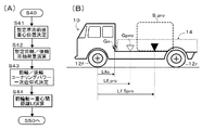
図1(A)は、自動車等の車両の前後方向の重心位置、前輪及び後輪の車軸荷重、コーナリングパワーを推定する本発明による車両状態推定装置の好ましい実施形態が搭載される車両10を示している。車両10は、公知の任意の形式の車両であってよく、一対の前輪12f及び一対の後輪12rと、任意の積載物Sが載置される荷台14とを有している。なお、図示の例では、簡単のため、車両後方部に上部が開放された荷台を有するトラックとして描かれているが、本発明の車両状態推定装置の搭載される車両は、箱型荷台を後方に有するトラック、前方にも荷台を有する車両、バス、その他の任意の積載物が積載可能な車両であってよい。FIG. 1A is a schematic diagram of an apparatus in which a preferred embodiment of a vehicle state estimation apparatus according to the present invention for estimating the center of gravity position of a vehicle such as an automobile, the axle loads of front and rear wheels, and cornering power is mounted. 10 is shown. The
一般に、車両の挙動、運動又は走行制御が実行される際、しばしば、車両の前後方向の重心位置(車軸−重心間距離)、前輪及び後輪の車軸荷重、コーナリングパワーといったパラメータが使用される場合がある。しかしながら、図示の如き車両10に於いて、上に列記された如きパラメータは、荷台14に積載される積載物Sの重量又はその配置に依存して変動する。勿論、前輪及び後輪の車軸に車軸荷重をセンサ等により直接検出できるようになっていれば(特許文献4)、上記の如きパラメータは、荷重センサの検出値に基づいて算出可能であるが、その場合、車軸荷重センサを車軸近傍に取り付けるための設計・工程に関わる労力及び費用が必要となる。そこで、本発明の車両状態推定装置では、車軸荷重センサを用いることなく、車両の使用中又は走行中に車両の前後方向の重心位置、前輪及び後輪の車軸荷重、コーナリングパワーを推定することが試みられる。
In general, when vehicle behavior, motion or travel control is executed, parameters such as the position of the center of gravity in the longitudinal direction of the vehicle (the distance between the axle and the center of gravity), the axle load of the front and rear wheels, and cornering power are often used. There is. However, in the
車両の運動制御の分野に於いて、「発明の開示」の欄に於いて述べた如く、しばしば、車両の旋回運動特性を記述する際の指標の一つとして、スタビリティファクタKHが用いられる。典型的な4輪車両(二輪モデル、即ち、左右輪のタイヤ力が等価である仮定したモデル)に於いて、スタビリティファクタKHは、

上記の式(7)に於いて、図1(A)から理解される如く、また、「発明の開示」の欄で述べた如く、L、Lf、Lrの間には、
L=Lf+Lr …(4)
が成立する。また、前輪及び後輪のコーナリングパワーKf、Krは、後に詳細に説明される如く、それぞれ前輪及び後輪の車軸荷重Mf、Mrの関数として表すことが可能であり(車軸荷重とコーナリングパワーの関係)、車軸荷重Mf、Mrは、鉛直方向の力のモーメントの釣り合いから、下記の式
Mf=M・Lr/L …(3a)
Mr=M・Lf/L …(3b)
により、前輪軸/後輪軸−重心間距離Lf、Lrに関連付けられる。結局、式(7)に於ける前輪及び後輪のコーナリングパワーKf、Krは、前輪軸/後輪軸−重心間距離Lf又はLrの関数として表されることになるので、式(7)をLf又はLrについて解けば、Lf又はLrが、車両重量M、スタビリティファクタKHの関数として表すことが可能である(上記式(6)参照)。かくして、本発明の装置では、任意の公知の手法で取得又は演算して得られる車両重量M、スタビリティファクタKHを用いて、Lf(又はLr)を算出し、しかる後にLr(又はLf)、前輪及び後輪の車軸荷重Mf、Mr、前輪及び後輪のコーナリングパワーKf、Krが算出される。In the above formula (7), as understood from FIG. 1 (A), and as described in the section of “Disclosure of the Invention”, between L, Lf and Lr,
L = Lf + Lr (4)
Is established. Further, the cornering powers Kf and Kr of the front wheels and the rear wheels can be expressed as functions of the axle loads Mf and Mr of the front wheels and the rear wheels, respectively, as will be described in detail later (Relationship between axle load and cornering power). ), And axle loads Mf and Mr are expressed by the following formula Mf = M · Lr / L (3a) from the balance of the moment of force in the vertical direction.
Mr = M · Lf / L (3b)
Thus, the distances Lf and Lr between the front wheel axis / rear wheel axis and the center of gravity are associated. Eventually, the cornering powers Kf and Kr of the front wheels and the rear wheels in Expression (7) are expressed as a function of the distance Lf or Lr between the front wheel axis / rear wheel axis and the center of gravity. Alternatively, if Lr is solved, Lf or Lr can be expressed as a function of the vehicle weight M and the stability factor KH (see the above formula (6)). Thus, in the apparatus of the present invention, Lf (or Lr) is calculated using the vehicle weight M and stability factor KH obtained or obtained by any known method, and then Lr (or Lf), Axle loads Mf and Mr of front wheels and rear wheels, and cornering powers Kf and Kr of front wheels and rear wheels are calculated.
装置の構成と作動
図1(B)は、本発明の一つの実施形態による車両状態推定装置及び周辺機器の構成をブロック図の形式で表したものである。なお、本実施形態の装置は、自動車等の車両に搭載された電子制御装置又はコンピュータ(双方向コモン・バスにより相互に連結されたCPU、ROM、RAM及び入出力ポート装置を有する通常の形式のものであってよい。)の、プログラムに従った作動により実現されてよい。同図を参照して、本発明の装置は、車両前後方向重心位置推定部50と、前後輪それぞれのコーナリングパワーと車軸荷重の関係を表すデータを記憶したデータメモリ50aと、車両重量推定部50bと、スタビリティファクタ推定部50cとを含む。図示の如く、車両重量推定部50bは、典型的には、車両の走行中の制駆動力値(又はこれを推定するためのスロットル開度、ブレーキ圧など)と前後加速度センサ等で検出された加減速度値との入力に基づき、公知の任意の手法(例えば、特許文献1に記載の方法であってよい。)により、現在の(積載物の重量を含む)車両の重量Mを推定する。スタビリティファクタ推定部50cは、ヨーレート値、車速値、舵角値、横加速度値等を用いて公知の任意の手法(例えば、特許文献2に記載の方法であってよい。)により、現在のスタビリティファクタ値KHを推定する。データメモリ50aには、後で説明される実施形態に於けるコーナリングパワーと車軸荷重との関係を表す関数の形式に依存して、関数の係数或いは予め実験的に(又は理論的に)得られたコーナリングパワー値と車軸荷重値の組のデータ群とが格納される。車両前後方向重心位置推定部50は、後に説明される態様にて、車両重量M、スタビリティファクタ値KH及びコーナリングパワーと車軸荷重との関係を表す関数の係数又はデータ群を適宜読み込み、前輪軸/後輪軸−重心間距離Lf、Lr、車軸荷重Mf、Mr、コーナリングパワーKf、Krを逐次算出し、それらの算出結果値が任意の運動制御装置等60に於いて利用できるようにする。なお、後に詳細に説明される実施形態の一つに於いて用いる目的で操舵応答時定数係数Tpを推定して、その値を車両前後方向重心位置推定部50へ出力する操舵応答時定数係数推定部50dが設けられていてよい。 Configuration and Operation of Device FIG. 1B shows the configuration of a vehicle state estimation device and peripheral devices according to one embodiment of the present invention in the form of a block diagram. The apparatus of this embodiment is an electronic control device or a computer (a CPU, a ROM, a RAM, and an input / output port device connected to each other by a bidirectional common bus) mounted on a vehicle such as an automobile. May be realized by operation according to a program. Referring to the drawing, the apparatus of the present invention includes a vehicle longitudinal center-of-gravity
図2は、車両前後方向重心位置推定部50に於ける演算処理の構成をフローチャートの形式で表したものである。図示の処理は、車両の走行中、所定の期間、反復して実行されてよい。同図を参照して、車両前後方向重心位置推定部50では、まず、車両重量M、スタビリティファクタ値KHがそれぞれ取得される(ステップ10、20)。次いで、車両重量Mを用いて、「車両前後方向重心位置閾値」、即ち、車両重量Mから算出される積載物が積載可能な荷台部分の最前方又は最後方に置かれていると仮定した場合の車両の前輪軸−重心間距離Lf_min、Lf_maxが算出される(ステップ30)。かかる閾値Lf_min、Lf_maxは、車両重量M、スタビリティファクタKHを用いて得られる車両の前輪軸−重心間距離の推定値Lfのガード処理に用いられる。そして、前輪軸−重心間距離Lf及び後輪軸重心間距離Lr(車両前後方向重心位置)の推定値が、下記に詳細に説明される態様のいずれかによって算出され(ステップ40)、前輪車軸荷重Mf、後輪車軸荷重Mr、前輪(等価)コーナリングパワーKf、後輪(等価)コーナリングパワーKrが算出される(ステップ50、60)。以下、上記の各ステップの演算処理について詳細に説明する。
FIG. 2 shows the configuration of the arithmetic processing in the vehicle longitudinal direction gravity center
(a)車両重量M、スタビリティファクタ値KHの取得(ステップ10、20)
既に触れたように、車両重量M、スタビリティファクタ値KHは、公知の任意の形式にて推定された値が用いられてよい。簡単には、例えば、車両重量Mは、直線走行中に車両を加減速したときの車両の発生駆動力(F)と加速度(α)との関係(又は発生制動力と減速度との関係)に走行抵抗Rを考慮して下記の式を用いて与えられる。
M=(F−R)/α …(8)
勿論、式(8)に限らず、種々の形式の車両重量の推定方法が用いられてよく、そのような場合も本発明の範囲に属する。また、スタビリティファクタ値KHは、簡単には、車両の定常旋回中のヨーレートγ、舵角δ、車速Vから
KH={(V・δ/L・γ)−1}/V2 …(9)
により算出可能である。なお、特許文献2の如く、ヨーレートの舵角に対する一次遅れを考慮して推定されるようになっていてもよく、そのような場合も本発明の範囲に属する。(A) Acquisition of vehicle weight M and stability factor value KH (steps 10 and 20)
As already mentioned, the vehicle weight M and the stability factor value KH may be values estimated in any known format. For example, the vehicle weight M is, for example, the relationship between the generated driving force (F) and the acceleration (α) of the vehicle when the vehicle is accelerated or decelerated during straight running (or the relationship between the generated braking force and the deceleration). In consideration of the running resistance R, the following equation is used.
M = (F−R) / α (8)
Of course, not only the equation (8) but also various types of vehicle weight estimation methods may be used, and such cases are also within the scope of the present invention. Further, the stability factor value KH can be simply calculated from the yaw rate γ, the steering angle δ, and the vehicle speed V during steady turning of the vehicle. KH = {(V · δ / L · γ) −1} / V 2 (9) )
Can be calculated. Note that, as disclosed in Patent Document 2, it may be estimated in consideration of a first-order delay with respect to the steering angle of the yaw rate, and such a case also belongs to the scope of the present invention.
(b)車両前後方向重心位置閾値の演算(ステップ30)
既に触れた如く、本発明の装置では、車両重量M、スタビリティファクタKHを用いて車両前後方向重心位置が推定される。しかしながら、変数パラメータとして用いられる車両重量M、スタビリティファクタKHの精度が低い場合又は後述のそれらの仮値が使用されている場合には、推定された車両前後方向重心位置が過剰に真の位置から外れてしまうことも起き得る。そこで、積載物の重量が決定された段階で、荷台の構成と積載物の重量とから想定可能な車両前後方向重心位置の範囲、即ち、閾値が算出される。(B) Calculation of vehicle longitudinal direction center of gravity position threshold (step 30)
As already mentioned, in the apparatus of the present invention, the position of the center of gravity in the vehicle longitudinal direction is estimated using the vehicle weight M and the stability factor KH. However, when the accuracy of the vehicle weight M and the stability factor KH used as the variable parameters is low, or when those temporary values described later are used, the estimated vehicle longitudinal center-of-gravity position is excessively the true position. It can happen that you are off the ground. Therefore, when the weight of the load is determined, a range of the center of gravity position in the vehicle front-rear direction, that is, a threshold value, is calculated from the configuration of the loading platform and the weight of the load.
詳細には、まず、車両重量Mと無積載時の車両の重量Moとから、積載物の重量Msが
Ms=M−Mo …(10)
により算出される。ここで、無積載時の車両の重量Moは、車両本体のみの重量、運転者の重量を含めた車両の重量或いは実際の乗員人数分の重量を含めた車両の重量である。(実際の乗員人数分の重量を考慮する場合、着座センサ又はシートベルトスイッチにより、実際の乗員人数が検出され、その人数に平均的な体重値が乗ぜられて得られる重量値が車両本体のみの重量に加算されてよい。)In detail, first, the weight Ms of the load is determined from the vehicle weight M and the weight Mo of the vehicle when there is no load. Ms = M−Mo (10)
Is calculated by Here, the weight Mo of the vehicle when not loaded is the weight of the vehicle including the weight of the vehicle body alone, the weight of the vehicle including the weight of the driver, or the weight of the actual number of passengers. (When considering the weight of the actual number of passengers, the actual number of passengers is detected by the seating sensor or seat belt switch, and the weight value obtained by multiplying the average weight value by that number is the vehicle body only. (It may be added to the weight.)
次いで、図3に示されている如く、積載物が荷台14の最前部Sminの位置にある場合の前輪軸−重心間距離Lf_minと、積載物が荷台14の最後部Smaxの位置にある場合の前輪軸−重心間距離Lf_maxとが下記の式により算出される。
Lf_min=(Mo・Lfo+Ms・Lf_Smin)/M …(11)
Lf_max=(Mo・Lfo+Ms・Lf_Smax)/M …(12)
ここで、Lf_Sminは、前輪軸−位置Smin間の前後方向距離であり、Lf_Smaxは、前輪軸−位置Smax間の前後方向距離であり、Lfoは、積載物を除いた車両の重心Goと前輪軸との間の前後方向距離である。かくして、下記のステップ40にて算出される前輪軸−重心間距離Lfは、
Lf_min≦Lf≦Lf_max …(13)
の条件を満たすことが期待され、もし範囲[Lf_min,Lf_max]を逸脱する場合には、Lfは、Lf_min又はLf_maxに設定されることとなる。なお、式(11)、(12)中、可変のパラメータは、Msだけである。従って、随時、式(11)、(12)を演算するのではなく、積載重量Msを変数としたLf_min,Lf_maxのマップがそれぞれ準備され、ステップ30に於いて、参照されるようになっていてもよい。Next, as shown in FIG. 3, the distance between the front wheel axle and the center of gravity Lf_min when the load is at the position of the foremost portion Smin of the
Lf_min = (Mo · Lfo + Ms · Lf_Smin) / M (11)
Lf_max = (Mo · Lfo + Ms · Lf_Smax) / M (12)
Here, Lf_Smin is the front-rear distance between the front wheel axis and the position Smin, Lf_Smax is the front-rear distance between the front wheel axis and the position Smax, and Lfo is the center of gravity Go and the front wheel axis of the vehicle excluding the load. The distance in the front-rear direction. Thus, the distance Lf between the front wheel axis and the center of gravity calculated in step 40 below is
Lf_min ≦ Lf ≦ Lf_max (13)
It is expected that the above condition will be satisfied, and if it deviates from the range [Lf_min, Lf_max], Lf will be set to Lf_min or Lf_max. Note that in the formulas (11) and (12), the only variable parameter is Ms. Accordingly, maps of Lf_min and Lf_max using the loaded weight Ms as a variable are prepared and referred to in step 30 instead of calculating equations (11) and (12) as needed. Also good.
(c)車両前後方向重心位置の演算(ステップ40)
「発明の開示」の欄に於いて述べた如く、本発明の装置では、式(7)のスタビリティファクタKHを与える式(式(1)の具体例)に於いて、式(2a)、(2b)、(3a)、(3b)、(4)の関係を用いて、式(7)から変数Kf、Kr及びLr(又はLf)を消去した式をLf(又はLr)ついて解いて得られる式(6)の形式の関数を用いて、前輪軸−重心間距離Lfが算出される。この点に関し、式(6)の構成は、式(2a)、(2b)の形式によって種々の態様が考えられる。以下、車両重量MとスタビリティファクタKHとを変数として、前輪軸−重心間距離Lfを算出する幾つかの例について説明する。(C) Calculation of vehicle front-rear direction gravity center position (step 40)
As described in the “Disclosure of the Invention” section, in the apparatus of the present invention, in the formula (specific example of formula (1)) that gives the stability factor KH of formula (7), formula (2a), Using the relations (2b), (3a), (3b), and (4), an expression obtained by eliminating the variables Kf, Kr, and Lr (or Lf) from Expression (7) is obtained by solving for Lf (or Lr). The front wheel shaft-center-of-gravity distance Lf is calculated using a function of the form of Equation (6). In this regard, the configuration of the formula (6) can have various modes depending on the formats of the formulas (2a) and (2b). Hereinafter, several examples of calculating the distance Lf between the front wheel shaft and the center of gravity using the vehicle weight M and the stability factor KH as variables will be described.
(i)例1−車軸荷重とコーナリングパワーの関係を二次関数式で表す場合
図4のグラフは、実験的に得られた車軸荷重に対するコーナリングパワーのデータ値をプロットしたものを表している。同図に於いて、白丸は、シングルタイヤの前輪の場合の値を示し、黒丸は、ダブルタイヤの後輪の場合の値を示している。図から理解される如く、車軸荷重に対するコーナリングパワーの値は、車軸荷重の増大に対して単調増加した後、飽和するよう変化する。かかるコーナリングパワー値は、同図の一点鎖線κf(II)、κr(II)により示されている如き車軸荷重Mf、Mrの二次関数式:
κf(II)=af・Mf2+bf・Mf+cf …(14a);
κr(II)=ar・Mr2+br・Mr+cr …(14b)
により近似的により良く表すことができる。そして、車軸荷重Mf、Mrは、式(3a)、(3b)、(4)を用いて、Lfの関数の形式で表される。そこで、本実施例では、式(2a)、(2b)として、式(14a)、(14b)を用いて式(7)をLfの関数の形式に変換した式から得られた式:
Lf=λ(KH,M,L,af,bf,cf,ar,br,cr) …(6a)
を用いてLfが算出される。式(14a)、(14b)に於ける定数係数af、bf、cf、ar、br、crは、予め実験的に得られた車軸荷重に対するコーナリングパワーのデータ値から、最小自乗法その他の任意の二次近似の手法を用いて決定されてよい。また、本例の構成に於いて、予め算出された式(14a)、(14b)に於ける定数係数af、bf、cf、ar、br、crがデータメモリに格納され、ステップ40の実行時に読み出されるようになっていてよい。なお、式(6a)の具体的な表式の記載は省略されるが、当業者に於いて算出可能であることは理解されるべきである。(I) Example 1-Case where the relationship between axle load and cornering power is expressed by a quadratic function equation The graph of Fig. 4 shows a plot of data values of cornering power with respect to axle load obtained experimentally. In the figure, white circles indicate values for the front wheels of a single tire, and black circles indicate values for the rear wheels of a double tire. As understood from the figure, the value of the cornering power with respect to the axle load changes so as to saturate after monotonically increasing with respect to the increase of the axle load. The cornering power value is expressed by a quadratic function expression of axle loads Mf and Mr as indicated by alternate long and short dash lines κf (II) and κr (II) in FIG.
κf (II) = af · Mf 2 + bf · Mf + cf (14a);
κr (II) = ar · Mr 2 + br · Mr + cr (14b)
Can be approximated better. The axle loads Mf and Mr are expressed in the form of a function of Lf using equations (3a), (3b), and (4). Therefore, in the present embodiment, as the expressions (2a) and (2b), the expression obtained from the expression obtained by converting the expression (7) into the function format of Lf using the expressions (14a) and (14b):
Lf = λ (KH, M, L, af, bf, cf, ar, br, cr) (6a)
Is used to calculate Lf. The constant coefficients af, bf, cf, ar, br, cr in the equations (14a), (14b) are calculated from the data values of the cornering power with respect to the axle load obtained experimentally in advance, and the least square method or any other arbitrary value. It may be determined using a quadratic approximation technique. In the configuration of this example, the constant coefficients af, bf, cf, ar, br, cr in the equations (14a) and (14b) calculated in advance are stored in the data memory, and when step 40 is executed, It may be read out. In addition, although description of the specific expression of Formula (6a) is abbreviate | omitted, it should be understood that it can be calculated by those skilled in the art.
(ii)例2−車軸荷重とコーナリングパワーの関係を一次関数式で表す場合
上記の例1に於いては、車軸荷重とコーナリングパワーの関係を表す式として、車軸荷重の二次関数が用いられたが、式(6a)の関数λの構成が複雑となり、演算負荷が増大する。そこで、本実施例では、式(2a)、(2b)として、図4中の実線κf(I)、κr(I)により示されている如く、コーナリングパワー値を車軸荷重の一次関数として表した式:
κf(I)=af・Mf+bf …(15a);
κr(I)=ar・Mr+br …(15b)
が用いられて得られた式(6)により、Lfが算出される。Lfの具体的な表式は、
Lf=(L/2)・(KH・L・af・M・ar-KH・L・af・br+KH・L・bf・ar+af・M+bf-ar・M+br+(2br・bf+KH2・L2・af2・br2-2KH・L・af・br2+KH2・L2・bf2・ar2+2KH・L・bf2・ar-2bf・ar・M+2ar・M・br+af2・M2+bf2+ar2・M2+br2+KH2・L2・af2・M2・ar2+2KH2・L2・af2・M・ar・br+2KH2・L2・af・M・ar2・bf+2KH・L・af2・M2・ar-2KH・L・af・M2・ar2+2KH2・L2・af・br・bf・ar+2KH・L・af2・br・M-2KH・L・bf・ar2・M+4KH・L・af・M・ar・bf-4KH・L・af・M・ar・br+2KH・L・af・br・bf-2KH・L・bf・ar・br-2af・M・br-2af・M2・ar+2af・M・bf)1/2)/((KH・L・af・ar+af-ar)M) …(16)
となる。式(15a)、(15b)に於ける定数係数af、bf、ar、brの具体的な値は、予め実験的に得られた車軸荷重に対するコーナリングパワーのデータ値から最小自乗法その他の任意の一次近似の手法を用いて決定されてよい。(Ii) Example 2-Case where the relationship between axle load and cornering power is expressed by a linear function expression In Example 1 above, a quadratic function of axle load is used as an expression representing the relationship between axle load and cornering power. However, the structure of the function λ in Expression (6a) becomes complicated, and the calculation load increases. In this embodiment, therefore, the cornering power value is expressed as a linear function of the axle load as shown by the solid lines κf (I) and κr (I) in FIG. 4 as equations (2a) and (2b). formula:
κf (I) = af · Mf + bf (15a);
κr (I) = ar · Mr + br (15b)
Lf is calculated by the equation (6) obtained by using. The specific expression of Lf is
Lf = (L / 2) ・ (KH ・ L ・ af ・ M ・ ar-KH ・ L ・ af ・ br + KH ・ L ・ bf ・ ar + af ・ M + bf-ar ・ M + br + (2br ・ bf + KH 2・ L 2・ af 2・ br 2 -2KH ・ L ・ af ・ br 2 + KH 2・ L 2・ bf 2・ ar 2 + 2KH ・ L ・ bf 2・ ar-2bf ・ ar ・ M + 2ar・ M ・ br + af 2・ M 2 + bf 2 + ar 2・ M 2 + br 2 + KH 2・ L 2・ af 2・ M 2・ ar 2 + 2KH 2・ L 2・ af 2・ M ・ ar・ Br + 2KH 2・ L 2・ af ・ M ・ ar 2・ bf + 2KH ・ L ・ af 2・ M 2・ ar-2KH ・ L ・ af ・ M 2・ ar 2 + 2KH 2・ L 2・ af ・br ・ bf ・ ar + 2KH ・ L ・ af 2・ br ・ M-2KH ・ L ・ bf ・ ar 2・ M + 4KH ・ L ・ af ・ M ・ ar ・ bf-4KH ・ L ・ af ・ M ・ ar ・br + 2KH ・ L ・ af ・ br ・ bf-2KH ・ L ・ bf ・ ar ・ br-2af ・ M ・ br-2af ・ M 2・ ar + 2af ・ M ・ bf) 1/2 ) / ((KH ・L ・ af ・ ar + af-ar) M)… (16)
It becomes. The specific values of the constant coefficients af, bf, ar, and br in the equations (15a) and (15b) are calculated from the data of the cornering power with respect to the axle load obtained experimentally in advance, and the least squares method and other arbitrary values. It may be determined using a first-order approximation technique.
(iii)例3−暫定車両前後方向重心位置を用いて車軸荷重とコーナリングパワーの関係を一次関数式で表す場合
車両の重心位置は実際の積載重量に依存して大きく変動する。従って、積載重量を考慮せずに、上記の例2の如く車軸荷重とコーナリングパワーの関係を一次近似式により表すと、実際の積載重量に依存して、算出された前輪軸−重心間距離Lfの精度が低下する可能性がある。実際、図4中のκf(II)とκf(I)、或いは、κr(II)とκr(I)の間の差分の大きさが大きくなっている部分が存在する(κf(I)、κr(I)は、想定される車軸荷重の全域に亙って車軸荷重値に対するコーナリングパワーのデータ値を一次近似することにより得られた。)。そこで、本実施例では、車軸荷重とコーナリングパワーの関係を一次近似式で表す際に利用する予め実験的に得られた車軸荷重に対するコーナリングパワーのデータ値の範囲を、実際の積載重量に於いて想定される範囲に制限することにより、車軸荷重とコーナリングパワーの関係の一次近似式の精度を向上し、これにより、算出されるLfの精度の向上が図られる。(iii) Example 3 When the relationship between the axle load and the cornering power is expressed by a linear function expression using the provisional vehicle longitudinal center-of-gravity position, the center-of-gravity position of the vehicle varies greatly depending on the actual loaded weight. Therefore, if the relationship between the axle load and the cornering power is expressed by a first-order approximation expression as in Example 2 above without considering the load weight, the calculated front wheel shaft-center of gravity distance Lf depends on the actual load weight. Accuracy may be reduced. In fact, there are portions where the magnitude of the difference between κf (II) and κf (I) or κr (II) and κr (I) in FIG. 4 is large (κf (I), κr (I) was obtained by linearly approximating the cornering power data value with respect to the axle load value over the entire assumed axle load. Therefore, in this embodiment, the range of the data value of the cornering power with respect to the axle load obtained experimentally in advance, which is used when the relationship between the axle load and the cornering power is expressed by a first-order approximation formula, is the actual load weight. By limiting to the assumed range, the accuracy of the first-order approximation relation between the axle load and the cornering power is improved, thereby improving the accuracy of the calculated Lf.
図5(A)は、本実施例に於けるステップ40の処理をより詳細にフローチャートの形式で表したものである。かかる処理に於いては、まず、図5(B)に例示されている如く、実際の積載物が荷台の適当な位置(例えば、荷台の中心)に置かれた状態S_proを仮定したときの暫定的な車両前後方向重心位置G_proを決定する(ステップ41)。具体的には、例えば、実際の積載物の重心が荷台の略中心に位置すると仮定して(前輪軸−荷台中心間距離Lf_Sproを仮定して)、暫定前輪軸−重心間距離Lf_pro、暫定後輪軸−重心間距離Lr_proが下記の式により決定される。
Lf_pro=(Mo・Lfo+Ms・Lf_Spro)/M …(17a)
Lr_pro=L−Lf_pro …(17b)
これにより、暫定の前輪軸荷重Mf_pro、暫定の後輪軸荷重Mr_proが下記の式により与えられる(ステップ42)。
Mf_pro=M・Lr_pro/L …(18a)
Mr_pro=M・Lf_pro/L …(18b)FIG. 5A shows the processing of step 40 in the present embodiment in more detail in the form of a flowchart. In this processing, first, as illustrated in FIG. 5B, a provisional when assuming a state S_pro in which an actual load is placed at an appropriate position of the loading platform (for example, the center of the loading platform). A vehicle longitudinal center-of-gravity position G_pro is determined (step 41). Specifically, for example, assuming that the center of gravity of the actual load is located substantially at the center of the loading platform (assuming the front wheel shaft-loading center distance Lf_Spro), the provisional front wheel shaft-centering distance Lf_pro, The distance Lr_pro between the wheel axis and the center of gravity is determined by the following equation.
Lf_pro = (Mo · Lfo + Ms · Lf_Spro) / M (17a)
Lr_pro = L−Lf_pro (17b)
Thus, the provisional front wheel axle load Mf_pro and the provisional rear wheel axle load Mr_pro are given by the following equations (step 42).
Mf_pro = M · Lr_pro / L (18a)
Mr_pro = M · Lf_pro / L (18b)
次いで、上記の如く得られた暫定の前輪軸荷重Mf_pro、暫定の後輪軸荷重Mr_proを略中心とした所定の範囲、例えば、±100kg、の車軸荷重値とそれらに対応するコーナリングパワーのデータ値を用いて、例2の如く、式(15a)、(15b)の形式のコーナリングパワーと車軸荷重との関係式、即ち、定数係数af、bf、ar、brが決定される(ステップ43)。かかる定数係数は、データメモリ50aに予め記憶されている、車両の使用中に想定される車軸荷重の全域に亙る車軸荷重値に対するコーナリングパワーのデータ値の群の中から暫定の前輪軸荷重Mf_pro、暫定の後輪軸荷重Mr_proを略中心とした所定の範囲のデータ値の群を読み出し、それらのデータ値群から最小自乗法その他の任意の一次近似の手法を用いて決定されてよい。この場合、図6に例示されている如く、一次近似に使用される値域が所定の範囲に制限されているため、実際のデータ値又は二次式κf(II)、κr(II)との差分が小さくなり、式(15a)、(15b)の形式のコーナリングパワーと車軸荷重の関係式の精度が向上されることが期待される。
Next, the provisional front wheel load Mf_pro and the provisional rear wheel load Mr_pro obtained as described above are set to a predetermined range about the center, for example, ± 100 kg, and the corresponding cornering power data values are obtained. As shown in Example 2, the relational expression between the cornering power and the axle load in the form of equations (15a) and (15b), that is, constant coefficients af, bf, ar, and br are determined (step 43). The constant coefficient is preliminarily stored in the
かくして、得られた定数係数af、bf、ar、brと、車両重量Mと、スタビリティファクタKHとから式(16)を用いて、前輪軸−重心間距離Lfが算出される。なお、暫定重心位置の決定時の積載物の重心位置は、荷台の中心に限らず、任意に設定されてよく、そのような場合も本発明の範囲に属することは理解されるべきである。図示の車両10の如き荷台が車両の後方に設置されている場合には、荷台の構造から積載物の配置個所は、或る程度限定される。従って、暫定重心位置の決定時の積載物の重心位置は、そのような荷台の構造に基づいて設定されてよい。
Thus, the front wheel shaft-center-of-gravity distance Lf is calculated from the obtained constant coefficients af, bf, ar, br, the vehicle weight M, and the stability factor KH using equation (16). It should be understood that the center-of-gravity position of the load at the time of determining the provisional center-of-gravity position is not limited to the center of the loading platform and may be arbitrarily set, and such a case also belongs to the scope of the present invention. When a loading platform such as the illustrated
(iv)例4−操舵応答特性から決定された暫定車両前後方向重心位置を用いて車軸荷重とコーナリングパワーの関係を一次関数式で表す場合
例3の如く決定された暫定的な車両前後方向重心位置G_proをコーナリングパワーと車軸荷重との関係を表す一次関数の決定に用いる場合、演算結果の精度を向上するためには、暫定的な車両前後方向重心位置G_proが真の重心位置にできるだけ近接していることが好ましい。本実施例では、そのようにできるだけ暫定的な車両前後方向重心位置G_proを真の重心位置に近接したものとするために、暫定的な車両前後方向重心位置G_proが車両の操舵応答特性を参照して決定される。特許文献2に記載されている如く、操舵応答特性の指標の一つである操舵応答時定数係数Tpは、車両のヨー慣性モーメントIの関数:
Tp=I/L2(1/Kf+1/Kr) …(19)
により与えられることが知られている。車両のヨー慣性モーメントIは、積載重量が重くなるほど増大するとともに、積載位置が車両の重心から離れるほど増大する。即ち、操舵応答時定数係数Tpは、積載重量が重くなるほど及び積載位置が車両の重心から離れるほど増大する。かくして、かかる操舵応答時定数係数と積載物の重量及び配置との関係を用いて、より精度よく、暫定的な車両前後方向重心位置G_proを決定することが試みられる。(Iv) Example 4-Case where the relationship between axle load and cornering power is expressed by a linear function expression using the provisional vehicle longitudinal center of gravity position determined from the steering response characteristic The provisional vehicle longitudinal center of gravity determined as in Example 3 When the position G_pro is used to determine a linear function representing the relationship between the cornering power and the axle load, in order to improve the accuracy of the calculation result, the temporary vehicle longitudinal center of gravity position G_pro is as close as possible to the true center of gravity position. It is preferable. In this embodiment, in order to make the provisional vehicle longitudinal direction gravity center position G_pro as close to the true gravity center position as possible, the provisional vehicle longitudinal direction gravity center position G_pro refers to the steering response characteristic of the vehicle. Determined. As described in Patent Document 2, the steering response time constant coefficient Tp, which is one of the indicators of the steering response characteristic, is a function of the yaw inertia moment I of the vehicle:
Tp = I / L 2 (1 /
It is known to be given by The yaw moment of inertia I of the vehicle increases as the loading weight increases, and increases as the loading position moves away from the center of gravity of the vehicle. That is, the steering response time constant coefficient Tp increases as the loading weight increases and the loading position moves away from the center of gravity of the vehicle. Thus, it is attempted to determine the provisional vehicle longitudinal direction center-of-gravity position G_pro with higher accuracy using the relationship between the steering response time constant coefficient and the weight and arrangement of the load.
具体的には、まず、操舵応答時定数係数推定部50dに於いて公知の任意の態様にて(特許文献2に記載された方法であってよい。)推定された操舵応答時定数係数Tpが取得される。そして、操舵応答時定数係数Tpと積載重量Msとをパラメータとした図7に示されている如き予め求められたマップを用いて暫定前輪軸−重心間距離Lf_proが決定される。図示されている車両10の如く、荷台14が車両の後方に設けられている場合には、図7に例示されている如く、積載重量Msが大きくなるほど、且つ、操舵応答時定数係数Tpが大きくなるほど、車両全体の重心は、後方へ移動し、前輪軸−重心間距離Lfが長くなることが理解される。かくして、決定された暫定前輪軸−重心間距離Lf_proを用いて、例3と同様に、暫定後輪軸−重心間距離Lr_pro、暫定の前輪軸荷重Mf_pro、暫定の後輪軸荷重Mr_proが順次決定され、式(15a)、(15b)の形式のコーナリングパワーと車軸荷重との関係式、即ち、定数係数af、bf、ar、brが決定される。そして、式(16)を用いて、前輪軸−重心間距離Lfが算出される。
Specifically, first, the steering response time constant coefficient Tp estimated by the steering response time constant
(v)例5−車軸荷重とコーナリングパワーの関係を表す一次関数式を収束演算により決定する場合
例3又は例4の如く、暫定前輪軸−重心間距離Lf_proの決定及びこれを用いた車軸荷重とコーナリングパワーの関係を表す一次関数式の決定を経て式(16)から推定算出された前輪軸−重心間距離Lfは、暫定前輪軸−重心間距離Lf_proよりも真の前輪軸−重心間距離Lfに近い値となっていることが期待される。従って、更に、一旦算出された前輪軸−重心間距離Lfを暫定前輪軸−重心間距離Lf_proに設定した状態にて、車軸荷重とコーナリングパワーの関係を表す一次関数式を決定すれば、更に、精度よく前輪軸−重心間距離Lfが推定されることが期待される。そこで、本実施例では、一旦推定された前輪軸−重心間距離Lfを暫定前輪軸−重心間距離Lf_proに設定して、かかる新たに設定された暫定前輪軸−重心間距離Lf_proを用いた車軸荷重とコーナリングパワーの関係を表す一次関数式の決定及び式(16)による前輪軸−重心間距離Lfの算出を、暫定前輪軸−重心間距離Lf_proと式(16)により得られた前輪軸−重心間距離Lfとの差分が十分に小さくなるまで反復することにより、前輪軸−重心間距離Lfの推定値の精度の向上が図られる。(V) Example 5: Determination of a linear function expression representing the relationship between axle load and cornering power by convergence calculation As in Example 3 or Example 4, determination of the provisional front wheel axle-center of gravity distance Lf_pro and axle load using the same The distance between the front wheel shaft and the center of gravity Lf estimated from the equation (16) through the determination of the linear function expression representing the relationship between the cornering power and the cornering power is a true front wheel axis-center of gravity distance than the provisional front wheel axis-center of gravity distance Lf_pro. It is expected to be a value close to Lf. Accordingly, if a linear function expression representing the relationship between the axle load and the cornering power is determined in a state where the calculated front wheel axis-center-of-gravity distance Lf is set to the provisional front wheel axis-center-of-gravity distance Lf_pro, It is expected that the distance Lf between the front wheel axis and the center of gravity is accurately estimated. Therefore, in this embodiment, the estimated front wheel axis-center-of-gravity distance Lf is set as the provisional front wheel axis-center-of-gravity distance Lf_pro, and the axle using the newly set provisional front wheel axis-center-of-gravity distance Lf_pro. Determination of the linear function expression representing the relationship between the load and the cornering power and calculation of the distance Lf between the front wheel axis and the center of gravity by the expression (16) are the front wheel axis obtained by the provisional front wheel axis-center distance Lf_pro and the expression (16). By repeating until the difference from the center-of-gravity distance Lf becomes sufficiently small, the accuracy of the estimated value of the front wheel shaft-center-of-gravity distance Lf can be improved.
図8は、本実施例に於けるステップ40の処理をより詳細にフローチャートの形式で表したものである。同図を参照して、まず、最初の暫定前輪軸−重心間距離Lf_proが例3又は例4で説明されている如く決定される(ステップ41)。しかる後、暫定後輪軸−重心間距離Lr_pro、暫定の前輪軸荷重Mf_pro、暫定の後輪軸荷重Mr_proの決定(ステップ42)、式(15a)、(15b)の定数係数af、bf、ar、brの決定(ステップ43)、式(16)による前輪軸−重心間距離Lfの算出(ステップ44)が実行される。かくして、前輪軸−重心間距離Lfが算出されると、LfとLf_proとの差分の大きさが所定の閾値より小さいか否か、即ち
|Lf−Lf_pro|<L(閾値) …(20)
が成立しているか否かが判定される(ステップ45)。ここで、もし条件(20)が成立していないと判定されたときには、算出されたLfをLf_proに設定し(ステップ46)、ステップ42、43及び44が繰り返される。そして、かかる処理が反復して実行された結果、条件(20)が成立したとき、そのときの算出された前輪軸−重心間距離Lfが最終的な前輪軸−重心間距離Lfとして決定される。FIG. 8 shows the process of step 40 in the present embodiment in more detail in the form of a flowchart. Referring to the figure, first, the first provisional front wheel shaft-center of gravity distance Lf_pro is determined as described in Example 3 or Example 4 (step 41). Thereafter, determination of the provisional rear wheel axis-center-of-gravity distance Lr_pro, provisional front wheel axle load Mf_pro, provisional rear wheel axle load Mr_pro (step 42), constant coefficients af, bf, ar, br of equations (15a) and (15b). (Step 43), and calculation of the distance Lf between the front wheel shaft and the center of gravity by the equation (16) (step 44) is executed. Thus, when the distance Lf between the front wheel shaft and the center of gravity is calculated, whether or not the magnitude of the difference between Lf and Lf_pro is smaller than a predetermined threshold, that is, | Lf−Lf_pro | <L (threshold) (20)
Is determined (step 45). If it is determined that the condition (20) is not satisfied, the calculated Lf is set to Lf_pro (step 46), and steps 42, 43 and 44 are repeated. When the condition (20) is satisfied as a result of repeatedly executing such processing, the calculated front wheel axis-center of gravity distance Lf at that time is determined as the final front wheel axis-center of gravity distance Lf. .
なお、ステップ45の判定に於いて、以下の場合は、条件(20)が成立していなくても、ステップ42、43及び44の反復実行(収束演算)を停止するようになっていてよい。
(1)収束演算を所定回数以上(例えば、3回以上)実行したとき。
(2)Lfの値が単調増加又は単調減少しないとき[最新のLfとその一つ前のLfとの差分の符号が逆転したとき。]。
(3)Lfの値が[Lf_min,Lf_max]の範囲から逸脱したとき。In the determination at step 45, in the following cases, the repeated execution (convergence calculation) of
(1) When the convergence calculation is executed a predetermined number of times or more (for example, three times or more).
(2) When the value of Lf does not monotonously increase or decrease monotonically [when the sign of the difference between the latest Lf and the previous Lf is reversed. ].
(3) When the value of Lf deviates from the range of [Lf_min, Lf_max].
(vi)例6−車両重量M、スタビリティファクタKHを変数パラメータとするマップを利用する場合
既に理解される如く、前輪軸−重心間距離Lfは、車両重量M、スタビリティファクタKHを変数として与えられる。そこで、図9に示される如き車両重量M、スタビリティファクタKHを変数パラメータとして前輪軸−重心間距離Lfを与えるマップを予め調製し、車両の走行中には、車両重量MとスタビリティファクタKHとの値からマップを参照して、前輪軸−重心間距離Lfを決定するようになっていてよい。この場合、上記の例1〜5の場合に比して、演算処理の負荷が大幅に低減される点で有利である。(Vi) Example 6: Using a map with vehicle weight M and stability factor KH as variable parameters As already understood, the distance Lf between the front wheel shaft and the center of gravity is determined by using vehicle weight M and stability factor KH as variables. Given. Therefore, a map that gives the distance Lf between the front wheel axle and the center of gravity is prepared in advance using the vehicle weight M and the stability factor KH as variable parameters as shown in FIG. 9, and the vehicle weight M and the stability factor KH are measured while the vehicle is running. The distance Lf between the front wheel shaft and the center of gravity L may be determined by referring to the map from the values. In this case, it is advantageous in that the load of the arithmetic processing is greatly reduced as compared with the cases of Examples 1 to 5 described above.
なお、例1〜6のいずれの場合に於いても、既に触れた如く、算出されたLfの値が前記の範囲[Lf_min,Lf_max]を逸脱する場合には、Lfは、Lf_min又はLf_maxに設定される(ガード処理)。即ち、
Lf<Lf_minのとき、Lf←Lf_min …(21a)
Lf_max<Lfのとき、Lf←Lf_max …(21b)
と設定される。In any case of Examples 1 to 6, as already mentioned, when the calculated value of Lf deviates from the range [Lf_min, Lf_max], Lf is set to Lf_min or Lf_max. (Guard processing) That is,
When Lf <Lf_min, Lf ← Lf_min (21a)
When Lf_max <Lf, Lf ← Lf_max (21b)
Is set.
かくして、上記の例1〜6のいずれかの態様により、前輪軸−重心間距離Lfが決定されると、
Lr=L−Lf …(22)
により、後輪軸−重心間距離が算出される。Thus, when the distance Lf between the front wheel shaft and the center of gravity is determined according to any one of the above Examples 1 to 6,
Lr = L−Lf (22)
Thus, the distance between the rear wheel shaft and the center of gravity is calculated.
(d)前輪車軸荷重Mf、後輪車軸荷重Mr、前輪(等価)コーナリングパワーKf、後輪(等価)コーナリングパワーKrの算出(ステップ50、60)
かくして、前輪軸−重心間距離Lfと後輪軸−重心間距離Lrが算出されると、式(3a)、(3b)を用いて、前輪車軸荷重Mf、後輪車軸荷重Mrがそれぞれ算出され(ステップ50)、式(14a)、(14b)[例1、6の場合]又は式(15a)、(15b)[例2〜5の場合]を用いて、前輪コーナリングパワーKf、後輪コーナリングパワーKrが算出される。(D) Calculation of front wheel axle load Mf, rear wheel axle load Mr, front wheel (equivalent) cornering power Kf, rear wheel (equivalent) cornering power Kr (steps 50, 60)
Thus, when the front wheel axis-center of gravity distance Lf and the rear wheel axis-center of gravity distance Lr are calculated, the front wheel axle load Mf and the rear wheel axle load Mr are calculated using equations (3a) and (3b), respectively ( Step 50), Expressions (14a) and (14b) [In the case of Examples 1 and 6] or Expressions (15a) and (15b) [In the case of Examples 2 to 5], the front wheel cornering power Kf, the rear wheel cornering power Kr is calculated.
(e)車両重量M又はスタビリティファクタ値KHが推定されていないとき
ところで、ステップ10又は20の実行時に車両重量M又はスタビリティファクタ値KHが推定されていないとき、例えば、車両の走行の開始後、車両重量Mが推定可能な直線加減速走行が実施されていないとき、或いは、スタビリティファクタ値KHが推定可能な旋回走行が実施されていないときには、車両重量M又はスタビリティファクタ値KHとして、仮値が用いられるようになっていてよい。例えば、車両重量Mが推定されていないときの車両重量Mの仮値は、規定された車両総重量、即ち、車両本体の重量と定員の重量と最大許容積載重量の規定値との和が用いられてよい(規定車両総重量を仮値とするのは、車両の運転者にとって、積載量が多いほど車両の操縦がしにくくなるためである。)。(E) When the vehicle weight M or the stability factor value KH is not estimated, and when the vehicle weight M or the stability factor value KH is not estimated at the time of execution of
一方、スタビリティファクタ値KHが推定されていないときのスタビリティファクタ値KHの仮値は、積載物が荷台の略中央に配置され、積載物の重心が荷台の中央にあると仮定して、式(7)を用いて算出されてよい。式(7)に於いて、スタビリティファクタ値KHを算出するためには、前輪軸−重心間距離Lf、後輪軸−重心間距離Lr、前後輪のコーナリングパワーKf、Krの各値が必要となる。かかる仮値のための前輪軸−重心間距離Lf、後輪軸−重心間距離Lrは、
Lf=(Mo・Lfo+(M−Mo)・Lfsc)/M …(22a)
Lr=L−Lf …(22b)
により算出されてよい。ここで、Moは、車両本体の重量(無積載時の重量)であり、Lfoは、車両本体の重心から前輪軸までの前後方向距離であり、Lfscは、荷台の中心から前後方向距離である(車両重量Mは、同値が推定されていないときは、前記の如く規定車両総重量であってよい。)。また、前後輪のコーナリングパワーKf、Krは、式(3a)、(3b)の関係式に式(22a)、(22b)の結果を代入して得られた車軸荷重値Mf、Mrを、上記の前後輪の各々のコーナリングパワーと車軸荷重Mf、Mrの予め得られている関係式(14a)、(14b)に代入することにより算出されてよい。On the other hand, when the stability factor value KH is not estimated, the provisional value of the stability factor value KH is assumed that the load is placed in the approximate center of the loading platform and the center of gravity of the loading is in the center of the loading platform. It may be calculated using equation (7). In Equation (7), in order to calculate the stability factor value KH, the front wheel shaft-center of gravity distance Lf, the rear wheel shaft-center of gravity distance Lr, and the front and rear wheel cornering powers Kf, Kr are required. Become. The front wheel axis-center of gravity distance Lf and the rear wheel axis-center of gravity distance Lr for such provisional values are:
Lf = (Mo · Lfo + (M−Mo) · Lfsc) / M (22a)
Lr = L−Lf (22b)
May be calculated by: Here, Mo is the weight of the vehicle body (weight when there is no load), Lfo is the longitudinal distance from the center of gravity of the vehicle body to the front wheel axle, and Lfsc is the longitudinal distance from the center of the loading platform. (The vehicle weight M may be the prescribed vehicle gross weight as described above when the same value is not estimated). Further, the cornering powers Kf and Kr of the front and rear wheels are obtained by substituting the axle load values Mf and Mr obtained by substituting the results of the expressions (22a) and (22b) into the relational expressions of the expressions (3a) and (3b), respectively. It may be calculated by substituting into the previously obtained relational expressions (14a) and (14b) of the cornering power and axle loads Mf and Mr of the front and rear wheels.
かくして、上記の本発明の装置によれば、車軸荷重をセンサ等で直接検出することなく、車両の前後方向の重心位置、前後輪の車軸荷重、コーナリングパワーが推定することが可能となる。 Thus, according to the above-described apparatus of the present invention, it is possible to estimate the position of the center of gravity in the longitudinal direction of the vehicle, the axle load of the front and rear wheels, and the cornering power without directly detecting the axle load with a sensor or the like.
以上に於いては本発明を特定の実施例について詳細に説明したが、本発明は上述の実施例に限定されるものではなく、本発明の範囲内にて他の種々の実施例が可能であることは当業者にとって明らかであろう。 Although the present invention has been described in detail with reference to specific embodiments, the present invention is not limited to the above-described embodiments, and various other embodiments are possible within the scope of the present invention. It will be apparent to those skilled in the art.
例えば、上記の例では、ステップ40に於いて、前輪軸−重心間距離Lfを初めに算出し、後輪軸−重心間距離Lrを算出しているが、スタビリティファクタKHの式(7)を後輪軸−重心間距離Lrについて解くことにより得られた式を用いて後輪軸−重心間距離Lrを先に算出し、式(4)の関係から、前輪軸−重心間距離Lfを算出するようになっていてもよい。 For example, in the above example, in Step 40, the distance Lf between the front wheel axis and the center of gravity is calculated first, and the distance Lr between the rear wheel axis and the center of gravity is calculated, but the stability factor KH equation (7) is calculated. The distance Lr between the rear wheel shaft and the center of gravity is first calculated using an equation obtained by solving for the distance between the rear wheel shaft and the center of gravity Lr, and the distance between the front wheel shaft and the center of gravity Lf is calculated from the relationship of Equation (4). It may be.
また、上記の例では、スタビリティファクタKHと前後輪軸−重心間距離とコーナリングパワーとの関係を表す式(1)として、二輪モデルを仮定して得られる式(7)を用いているが、式(1)に相当する関係式として、車両の構造に応じて別の式が用いられてよく、そのような場合も本発明の範囲に属することは理解されるべきである。 Moreover, in said example, although Formula (7) obtained on the assumption of a two-wheel model is used as Formula (1) showing the relationship between stability factor KH, the distance between front-and-rear wheel axis-center of gravity, and cornering power, As a relational expression corresponding to the expression (1), another expression may be used according to the structure of the vehicle, and it should be understood that such a case also belongs to the scope of the present invention.
Claims (11)
Applications Claiming Priority (1)
| Application Number | Priority Date | Filing Date | Title |
|---|---|---|---|
| PCT/JP2009/050271 WO2010082288A1 (en) | 2009-01-13 | 2009-01-13 | Vehicle condition estimating device |
Publications (2)
| Publication Number | Publication Date |
|---|---|
| JPWO2010082288A1 JPWO2010082288A1 (en) | 2012-06-28 |
| JP5141778B2 true JP5141778B2 (en) | 2013-02-13 |
Family
ID=42339557
Family Applications (1)
| Application Number | Title | Priority Date | Filing Date |
|---|---|---|---|
| JP2010546474A Expired - Fee Related JP5141778B2 (en) | 2009-01-13 | 2009-01-13 | Vehicle state estimation device |
Country Status (5)
| Country | Link |
|---|---|
| US (1) | US9096232B2 (en) |
| EP (1) | EP2380795B1 (en) |
| JP (1) | JP5141778B2 (en) |
| CN (1) | CN102282052B (en) |
| WO (1) | WO2010082288A1 (en) |
Families Citing this family (25)
| Publication number | Priority date | Publication date | Assignee | Title |
|---|---|---|---|---|
| DE112009005281B4 (en) * | 2009-09-24 | 2019-07-11 | Toyota Jidosha Kabushiki Kaisha | Method and device for estimating a rotational characteristic of a vehicle |
| JP5636825B2 (en) * | 2010-08-31 | 2014-12-10 | 株式会社アドヴィックス | Vehicle weight estimation device |
| DE102010063436A1 (en) * | 2010-12-17 | 2012-06-21 | Robert Bosch Gmbh | Method and device for determining a range of a vehicle |
| JP5592832B2 (en) * | 2011-05-17 | 2014-09-17 | 日立建機株式会社 | Electric drive dump truck |
| JP5710386B2 (en) * | 2011-06-02 | 2015-04-30 | 日立建機株式会社 | Electric drive dump truck |
| US9823111B2 (en) | 2011-12-27 | 2017-11-21 | Toyota Jidosha Kabushiki Kaisha | Method and device for estimating loading state of vehicle |
| JP5533903B2 (en) | 2012-01-27 | 2014-06-25 | トヨタ自動車株式会社 | Vehicle control device |
| EP2818378B1 (en) * | 2012-02-24 | 2020-07-29 | Toyota Jidosha Kabushiki Kaisha | Turning characteristic estimating device for vehicle |
| GB201205000D0 (en) * | 2012-03-22 | 2012-05-09 | Schrader Electronics Ltd | System and method for momitoring vehicle load dynamics |
| US9358846B2 (en) | 2012-10-19 | 2016-06-07 | The Goodyear Tire & Rubber Company | Vehicle weight and center of gravity estimation system and method |
| WO2014136188A1 (en) * | 2013-03-04 | 2014-09-12 | トヨタ自動車株式会社 | Method for calculating reference motion state amount of vehicle |
| JP5914448B2 (en) | 2013-11-01 | 2016-05-11 | ヤマハ発動機株式会社 | Saddle-type vehicle and wheel force acquisition device |
| FR3014557B1 (en) * | 2013-12-05 | 2017-02-10 | Renault Sa | METHOD FOR ESTIMATING THE MASS OF A VEHICLE |
| WO2015164246A1 (en) * | 2014-04-22 | 2015-10-29 | Michael Hall | Determining haul weight |
| GB2535773B (en) * | 2015-02-27 | 2019-10-30 | Jaguar Land Rover Ltd | Vehicle mass estimation |
| US10011284B2 (en) * | 2016-07-13 | 2018-07-03 | Mitsubishi Electric Research Laboratories, Inc. | System and method for determining state of stiffness of tires of vehicle |
| CN107618402B (en) * | 2017-09-20 | 2019-07-26 | 中国重汽集团济南动力有限公司 | Distribution driving Automobile shaft load calculation method and driving moment control method |
| CN108556850B (en) * | 2018-04-18 | 2019-08-23 | 吉林大学 | A kind of multi-axle heavy type wheel of vehicle vertical load general calculation method |
| US11066081B2 (en) * | 2018-05-01 | 2021-07-20 | Ford Global Technologies, Llc | Methods and apparatus to modify vehicle function based on loading conditions |
| CN109190147B (en) * | 2018-07-16 | 2023-05-16 | 深圳怡丰自动化科技有限公司 | Maximum bending moment acquisition method and device for vehicle carrying plate and device with storage function |
| JP6905566B2 (en) * | 2019-10-30 | 2021-07-21 | 先進モビリティ株式会社 | Vehicle center of gravity position estimation system |
| CN111186445B (en) * | 2020-01-20 | 2021-11-30 | 北京主线科技有限公司 | Lateral control method and system for automatic driving vehicle |
| JP6912635B1 (en) * | 2020-07-29 | 2021-08-04 | 先進モビリティ株式会社 | How to estimate the position of the center of gravity of a vehicle |
| CN112706778B (en) * | 2021-01-15 | 2022-04-08 | 一汽解放汽车有限公司 | Vehicle mass center identification method, vehicle and storage medium |
| KR102331807B1 (en) * | 2021-04-16 | 2021-12-02 | 국방과학연구소 | Electronic device for controlling driving of vehicle and operation method thereof |
Citations (4)
| Publication number | Priority date | Publication date | Assignee | Title |
|---|---|---|---|---|
| JPH0699758A (en) * | 1992-09-17 | 1994-04-12 | Fuji Heavy Ind Ltd | Torque distribution control method for four-wheel drive vehicle |
| JPH10338496A (en) * | 1997-06-11 | 1998-12-22 | Toyota Autom Loom Works Ltd | Oscillation controller and front and rear center of gravity position assuming device of industrial vehicle |
| JP2005184971A (en) * | 2003-12-18 | 2005-07-07 | Nissan Motor Co Ltd | Motor output controller for electric vehicle |
| JP2005239011A (en) * | 2004-02-26 | 2005-09-08 | Mitsubishi Motors Corp | Power steering device for vehicle and disturbance estimation device for vehicle |
Family Cites Families (24)
| Publication number | Priority date | Publication date | Assignee | Title |
|---|---|---|---|---|
| US2443098A (en) * | 1937-10-08 | 1948-06-08 | Rca Corp | Apparatus for determining the weight and center of gravity of vehicles |
| US3443077A (en) * | 1963-07-12 | 1969-05-06 | Jerome Lettvin | Method of and apparatus for center of gravity computation and the like |
| GB1530125A (en) * | 1974-11-27 | 1978-10-25 | Cl Instr Ltd | Axle load monitoring systems |
| US5416706A (en) * | 1984-04-27 | 1995-05-16 | Hagenbuch; Leroy G. | Apparatus for identifying containers from which refuse is collected and compiling a historical record of the containers |
| US4848508A (en) * | 1987-10-05 | 1989-07-18 | Borg-Warner Automotive, Inc. | Method and apparatus for controlling wheel slip in a full-time four wheel drive vehicle |
| DE4134240C2 (en) * | 1991-10-16 | 1995-12-14 | Mannesmann Ag | Steering support for a non-track-bound vehicle |
| US5671143A (en) * | 1994-11-25 | 1997-09-23 | Itt Automotive Europe Gmbh | Driving stability controller with coefficient of friction dependent limitation of the reference yaw rate |
| US5774821A (en) * | 1994-11-25 | 1998-06-30 | Itt Automotive Europe Gmbh | System for driving stability control |
| EP0798615B1 (en) * | 1996-02-27 | 2002-01-02 | KNORR-BREMSE SYSTEME FÜR NUTZFAHRZEUGE GmbH | Procedure for drive stability enhancement |
| JP3629916B2 (en) | 1997-09-18 | 2005-03-16 | 三菱ふそうトラック・バス株式会社 | Stability factor derivation method and target yaw rate setting method for front biaxial vehicle |
| DE10014220A1 (en) * | 2000-03-22 | 2001-09-27 | Bosch Gmbh Robert | Transverse acceleration determination method for vehicle, involves obtaining load signal along with wheel speed signal and calculating gravity center height with transverse acceleration using specific algorithm |
| GB0106925D0 (en) * | 2001-03-20 | 2001-05-09 | Lucas Industries Ltd | Steering control during ABS split MU operation |
| JP3448573B2 (en) | 2001-05-09 | 2003-09-22 | 株式会社豊田中央研究所 | Vehicle mass calculation device |
| JP3829934B2 (en) | 2002-06-27 | 2006-10-04 | トヨタ自動車株式会社 | Vehicle turning characteristic estimation device |
| DE10243516A1 (en) * | 2002-09-19 | 2004-04-01 | Robert Bosch Gmbh | Device for determining a total mass of a vehicle |
| DE10333654B4 (en) * | 2003-07-24 | 2005-09-29 | Bayerische Motoren Werke Ag | Control device for an at least temporarily four-wheel drive motor vehicle |
| KR20060120061A (en) * | 2003-10-28 | 2006-11-24 | 콘티넨탈 테베스 아게 운트 코. 오하게 | Method and system for improving the maneuverability of the vehicle |
| DE10358335B3 (en) * | 2003-12-12 | 2005-05-25 | Siemens Ag | Arrangement for determining dynamic axle loads and/or wheel loads of wheeled vehicle has evaluation device combined with measurement device to use linear accelerations, rotation rates to determine at least one axle load and/or wheel load |
| JP2005199882A (en) | 2004-01-16 | 2005-07-28 | Nsk Ltd | Traveling condition stabilizer for vehicle |
| DE102004046008B4 (en) * | 2004-09-16 | 2012-01-26 | Getrag Driveline Systems Gmbh | Drive train and method for driving a drive train |
| DE102005004523A1 (en) * | 2005-01-31 | 2006-08-10 | Zf Friedrichshafen Ag | Method for determining a control specification of an active steering device of a vehicle which can be controlled by a control device |
| US7388475B2 (en) * | 2006-01-19 | 2008-06-17 | Gm Global Technology Operations, Inc. | Lane departure warning and avoidance system with warning modification criteria |
| JP2008024235A (en) * | 2006-07-24 | 2008-02-07 | Equos Research Co Ltd | Vehicle |
| DE102006049541B4 (en) * | 2006-10-20 | 2018-10-31 | Volkswagen Ag | Method and device for determining a trailer support load |
-
2009
- 2009-01-13 WO PCT/JP2009/050271 patent/WO2010082288A1/en active Application Filing
- 2009-01-13 JP JP2010546474A patent/JP5141778B2/en not_active Expired - Fee Related
- 2009-01-13 US US13/131,408 patent/US9096232B2/en not_active Expired - Fee Related
- 2009-01-13 EP EP09838258.3A patent/EP2380795B1/en active Active
- 2009-01-13 CN CN200980154475.3A patent/CN102282052B/en not_active Expired - Fee Related
Patent Citations (4)
| Publication number | Priority date | Publication date | Assignee | Title |
|---|---|---|---|---|
| JPH0699758A (en) * | 1992-09-17 | 1994-04-12 | Fuji Heavy Ind Ltd | Torque distribution control method for four-wheel drive vehicle |
| JPH10338496A (en) * | 1997-06-11 | 1998-12-22 | Toyota Autom Loom Works Ltd | Oscillation controller and front and rear center of gravity position assuming device of industrial vehicle |
| JP2005184971A (en) * | 2003-12-18 | 2005-07-07 | Nissan Motor Co Ltd | Motor output controller for electric vehicle |
| JP2005239011A (en) * | 2004-02-26 | 2005-09-08 | Mitsubishi Motors Corp | Power steering device for vehicle and disturbance estimation device for vehicle |
Also Published As
| Publication number | Publication date |
|---|---|
| CN102282052B (en) | 2014-11-26 |
| EP2380795A4 (en) | 2016-10-26 |
| JPWO2010082288A1 (en) | 2012-06-28 |
| EP2380795A1 (en) | 2011-10-26 |
| EP2380795B1 (en) | 2019-09-11 |
| CN102282052A (en) | 2011-12-14 |
| US9096232B2 (en) | 2015-08-04 |
| US20110257876A1 (en) | 2011-10-20 |
| WO2010082288A1 (en) | 2010-07-22 |
Similar Documents
| Publication | Publication Date | Title |
|---|---|---|
| JP5141778B2 (en) | Vehicle state estimation device | |
| JP5177286B2 (en) | Vehicle weight-related physical quantity estimation device and control device | |
| US6662097B2 (en) | System for computing a road surface frictional coefficient | |
| JP6056954B2 (en) | Vehicle running motion control device | |
| US8504273B2 (en) | Coefficient of friction based limitation of the torque of a vehicle control loop | |
| US20190217854A1 (en) | Vehicle stability control system and method | |
| US9823111B2 (en) | Method and device for estimating loading state of vehicle | |
| US20120316744A1 (en) | Vehicle control system | |
| US11648933B2 (en) | Method for controlling wheel slip of vehicle | |
| EP2692605B1 (en) | Vehicle driving force control device | |
| US12252130B2 (en) | Method for controlling traveling of vehicle | |
| JP5958643B2 (en) | Calculation method of vehicle reference motion state quantity | |
| CN114248774B (en) | Vehicle curve control method, device, computer equipment and storage medium | |
| JP5211995B2 (en) | Vehicle deceleration control apparatus and method | |
| GB2368918A (en) | A system for determining the centre-of-gravity height of a vehicle | |
| JP6577850B2 (en) | Vehicle control apparatus and vehicle control method | |
| CN115675400A (en) | Method for controlling braking and/or traction of a vehicle | |
| US20070027605A1 (en) | Load transfer adaptive traction control system | |
| JP5089558B2 (en) | Road friction coefficient estimation device | |
| KR20220043983A (en) | Apparatus and method for improving turning performance of vehicle | |
| JP5754265B2 (en) | Tire contact length estimation device | |
| CN117657115A (en) | Vehicle stability control method and device, storage medium and vehicle | |
| WO2023210534A1 (en) | Control device for vehicle | |
| WO2023210533A1 (en) | Vehicle control device | |
| JP2024518686A (en) | Method for determining slip limits of vehicle wheels - Patents.com |
Legal Events
| Date | Code | Title | Description |
|---|---|---|---|
| TRDD | Decision of grant or rejection written | ||
| A01 | Written decision to grant a patent or to grant a registration (utility model) |
Free format text: JAPANESE INTERMEDIATE CODE: A01 Effective date: 20121023 |
|
| A01 | Written decision to grant a patent or to grant a registration (utility model) |
Free format text: JAPANESE INTERMEDIATE CODE: A01 |
|
| A61 | First payment of annual fees (during grant procedure) |
Free format text: JAPANESE INTERMEDIATE CODE: A61 Effective date: 20121105 |
|
| FPAY | Renewal fee payment (event date is renewal date of database) |
Free format text: PAYMENT UNTIL: 20151130 Year of fee payment: 3 |
|
| R151 | Written notification of patent or utility model registration |
Ref document number: 5141778 Country of ref document: JP Free format text: JAPANESE INTERMEDIATE CODE: R151 |
|
| LAPS | Cancellation because of no payment of annual fees |