JP5138191B2 - Airbag device - Google Patents
Airbag device Download PDFInfo
- Publication number
- JP5138191B2 JP5138191B2 JP2006218769A JP2006218769A JP5138191B2 JP 5138191 B2 JP5138191 B2 JP 5138191B2 JP 2006218769 A JP2006218769 A JP 2006218769A JP 2006218769 A JP2006218769 A JP 2006218769A JP 5138191 B2 JP5138191 B2 JP 5138191B2
- Authority
- JP
- Japan
- Prior art keywords
- airbag
- base fabric
- inflated
- vent hole
- fabric
- Prior art date
- Legal status (The legal status is an assumption and is not a legal conclusion. Google has not performed a legal analysis and makes no representation as to the accuracy of the status listed.)
- Expired - Fee Related
Links
Images


Landscapes
- Air Bags (AREA)
Description
本発明は、エアバッグ装置に関し、特に、挙動が特定しがたい保護対象者が車両に衝突した時の衝撃緩和を図るための、車両に搭載されるエアバッグ装置に関する。 The present invention relates to an airbag apparatus, and more particularly to an airbag apparatus mounted on a vehicle for mitigating impact when a person whose protection is difficult to specify collides with the vehicle.
例えば、走行中の車両が歩行者等に衝突した場合、その歩行者等は衝突時の衝撃によりボンネット上に跳ね上げられ、車両のフロントガラスを打ち破って車内に飛び込んだり、フロントピラー等に衝突するなど二次衝突して大惨事を引き起こす恐れがある。
そこで、このような二次衝突による衝撃を吸収緩和するため、歩行者用のエアバッグ装置が種々提案されているが、歩行者用のエアバッグでは、エアバッグで保護する対象(歩行者)がエアバッグに侵入するまでエアバッグを比較的長く膨張を維持する必要がある。
For example, when a traveling vehicle collides with a pedestrian or the like, the pedestrian or the like jumps up on the hood by the impact at the time of the collision, breaks the windshield of the vehicle and jumps into the vehicle, or collides with a front pillar or the like There is a risk of a catastrophe in a secondary collision.
Therefore, various types of airbag devices for pedestrians have been proposed in order to absorb and relieve the impact caused by such secondary collisions. However, in pedestrian airbags, an object (pedestrian) to be protected by an airbag is It is necessary to maintain the inflation of the airbag for a relatively long time until it enters the airbag.
一般に、歩行者用のエアバッグ装置は、車両が歩行者に衝突した時、その衝撃によりインフレータで発生したガスをエアバッグに導入して膨張展開し、その状態で跳ね上げられて飛んでくる歩行者を受け止めて、衝撃を緩和するともに、前記二次衝突を防止するようになっている。 In general, when a vehicle collides with a pedestrian, a pedestrian airbag device introduces gas generated in an inflator due to the impact to the airbag, inflates and deploys, and the pedestrian airbag device jumps up and flies in that state. The person is received and the impact is reduced, and the secondary collision is prevented.
しかしながら、跳ね上げられた人がそのまま膨張したエアバッグに衝突すると、その衝撃で人が重大な損傷を受ける恐れがある。とくに、車と衝突して飛ばされた人は通常頭から運転席側に飛び込んでくるから、膨張中のエアバッグに侵入するとその反発力で、頭部に重大な損傷を与える恐れがある。 However, if a person who is thrown up collides with an inflated airbag as it is, the person may be seriously damaged by the impact. In particular, since a person who collides with a car usually jumps from the head to the driver's seat side, entering the inflating airbag may cause serious damage to the head due to the repulsive force.
そこで、歩行者が膨張展開状態のエアバッグに侵入したときの衝撃を緩和するため、エアバッグの一部にガス抜きホール(又は排気用ベントホール)を形成して過剰な圧力を緩和するようにしたものが知られている(特許文献1参照)。 Therefore, in order to relieve the impact when a pedestrian enters an inflated and deployed airbag, a vent hole (or exhaust vent hole) is formed in a part of the airbag to relieve excessive pressure. Is known (see Patent Document 1).
しかしながら、エアバッグに単にベントホールを形成しただけの構造では、衝撃吸収前の段階でガス抜けてしまい、エアバッグの膨張を維持することができないため初期段階での適切な衝撃吸収特性が得られない虞がある。
本発明は、エアバッグ装置の上記問題を解決しようとするもので、その目的は、ボンネット上に跳ね上げられた歩行者などがエアバッグに衝突するまではガス抜きは行われず、歩行者などの衝突に合わせたタイミングでガス抜きをして、エアバッグ装置の安全性を向上させると共に、歩行者などの二次衝突の衝撃を緩和できるようにすることで、かつ、そのようなエアバッグ装置を簡易な構成で実現することにより、エアバッグ装置を低コストで得ることができるようにすることである。 The present invention is intended to solve the above-described problem of the airbag device, and its purpose is that the pedestrian or the like jumped up on the bonnet is not degassed until it collides with the airbag. By degassing at the timing in accordance with the collision, the safety of the airbag device is improved, and the impact of the secondary collision of a pedestrian or the like can be reduced, and such an airbag device is provided. By realizing with a simple configuration, an airbag device can be obtained at low cost.
請求項1の発明は、インフレータから発生するガスにより膨張する表面側基布及び裏面側基布と、エアバッグの膨張を規制する内部テザーからなるエアバッグを備えたエアバッグ装置であって、前記エアバッグの表面側基布に排気用ベントホールを設け、前記エアバッグの膨張時に、前記表面側基布に当接して前記排気用ベントホールを覆う部分と前記内部テザーで膨張が規制された前記表面側基布との間に空間を形成する部分とを備えた第三の基布の両側部を、前記表面側基布に糸で縫合し、前記エアバッグの膨張状態において、該エアバッグの前記第三の基布に人が侵入することにより、該エアバッグの膨張で前記第三の基布の一方の端部を縫合する糸が切れて前記表面側基布から外して前記排気用ベントホールを開放することを特徴とする。
請求項2の発明は、請求項1に記載されたエアバッグ装置において、前記第三の基布の縫合側部の少なくとも一方の端部を、前記膨張状態のエアバッグの前記第三の基布に人が侵入したときに、該エアバッグの前記第三の基布により膨張が規制される部分と、これに隣接する膨張が規制されない部分との境界部近傍に設けたことを特徴とする。
請求項3の発明は、請求項1又は2に記載されたエアバッグ装置において、前記エアバッグの内部を複数列の内部テザーで区画したことを特徴とする。
請求項4の発明は、請求項1ないし3のいずれかに記載されたエアバッグ装置において、前記表面側基布に前記排気用ベントホールに間隔を隔てて設けられ、前記エアバッグの膨張時に前記第三の基布で閉鎖される第2のベントホールが設けられていることを特徴とする。
請求項5の発明は、請求項1ないし4のいずれかに記載されたエアバッグ装置において、前記第三の基布の長さは前記エアバッグの膨張時に該エアバッグの膨張によるテンションが作用しない長さであることを特徴とする。
請求項6の発明は、請求項1ないし5のいずれかに記載されたエアバッグ装置において、前記エアバッグの裏面側基布に、前記エアバッグの膨張時に該エアバッグの裏面側の横方向への膨張を規制する第四の基布を設けたことを特徴とする。
請求項7の発明は、請求項1ないし6のいずれかに記載されたエアバッグ装置において、車両のボンネットの後端縁に沿う開口より展開することを特徴とする。
The invention of
According to a second aspect of the present invention, in the airbag device according to the first aspect , at least one end of the stitching side portion of the third base fabric is connected to the third base fabric of the airbag in the inflated state. The air bag is provided in the vicinity of a boundary portion between a portion of the airbag whose expansion is restricted by the third base fabric and a portion adjacent to the portion where the expansion is not restricted.
According to a third aspect of the present invention, in the airbag apparatus according to the first or second aspect , the interior of the airbag is partitioned by a plurality of rows of internal tethers.
According to a fourth aspect of the present invention, in the airbag device according to any one of the first to third aspects, the front-side base cloth is provided with an interval from the exhaust vent hole, and the airbag is inflated when the airbag is inflated. A second vent hole that is closed by a third base fabric is provided.
According to a fifth aspect of the present invention, in the airbag device according to any one of the first to fourth aspects, the length of the third base fabric is such that no tension is applied by the expansion of the airbag when the airbag is expanded. It is characterized by a length.
According to a sixth aspect of the present invention, in the airbag device according to any one of the first to fifth aspects, the back surface side base fabric of the airbag is moved laterally on the back surface side of the airbag when the airbag is inflated. A fourth base fabric that regulates the expansion of is provided.
A seventh aspect of the invention is the airbag device according to any one of the first to sixth aspects, wherein the airbag device is deployed from an opening along a rear end edge of a vehicle bonnet.
(作用)
本発明のエアバッグ装置は、人がエアバッグに侵入したときの衝撃を利用して排気用のベントホールを開口することで、エアバッグのガス抜きをタイミング良く行い衝撃荷重を低減する。
(Function)
The airbag apparatus according to the present invention opens an exhaust vent hole by using an impact when a person enters the airbag, thereby degassing the airbag in a timely manner and reducing an impact load.
本発明によれば、膨張するエアバッグに人が侵入したときに、そのタイミングに合わせて反発力を軽減することで侵入した人が受ける衝撃を緩和して、安全に受け止めることができる。また、エアバッグ装置を簡易な構成としたことにより低コストで得ることができる。 According to the present invention, when a person enters an inflating airbag, the impact received by the invading person can be reduced and received safely by reducing the repulsive force in accordance with the timing. Further, since the airbag device has a simple configuration, it can be obtained at low cost.
以下、本発明の1実施形態に係るエアバッグ装置を図面を参照して説明する。
図1は、本発明のエアバッグ装置を装着した車両の要部側面図である。同図に示すように、本発明のエアバッグ装置1は、車両2のボンネット3の後部3a内側部分に、支持機構4を介して折り畳まれた状態で収納されている。ボンネット3は、その後部3aが上下に開閉するようになっており、通常は周知の保持機構により閉じた下降位置に保持されている。図中、5はフロントウインドウガラス、6はフロントピラー、7はダッシュパネル、8はフェンダーパネルである。
Hereinafter, an airbag device according to an embodiment of the present invention will be described with reference to the drawings.
FIG. 1 is a side view of an essential part of a vehicle equipped with an airbag device of the present invention. As shown in FIG. 1, the
図2は、前記エアバッグ装置の展開状態の斜視図、図3は図2の矢視I−Iでみた断面図である。
エアバッグ装置1は、エアバッグ10と、衝突時にこのエアバッグ10内に膨張ガスを送出して膨張させるインフレータ11とを備えている。エアバッグ10は、袋状のエアバッグ本体12と、エアバッグ本体12内に取り付けられた膨張を規制する内部テザー13(図3参照)とで構成されている。
FIG. 2 is a perspective view of the airbag device in a deployed state, and FIG. 3 is a cross-sectional view taken along the line II of FIG.
The
エアバッグ本体12は、図2中上部側の幅広の略矩形の袋体であるピラー部12aと、下部側の幅狭の管状の袋体である基部12bからなり、図3に示すように、人の衝突面となる表面側基布14及び裏面側基布15とを、外周縁部に沿った縫合部16で縫合することにより、袋状に形成される。
なお、表面側基布14および裏面側基布15としては、一般にエアバッグに採用されている布や合成樹脂などの生地材料を使用することができる。
The airbag
In addition, as the surface
図2又は図3に示すように、表面側基布14の一側端部の縫合部16に近い部分にベントホール18が形成されている。
他方、前記エアバッグ10の表面側基布14の表面には、図2に示すように、展開時に略矩形のピラー部12aよりも縦方向幅が狭く、かつその横方向はその自由長さよりも短い略矩形の第三の基布20が設けられている。この第三の基布20は伸張性のない生地からなり、その図示幅方向両端部が前記縫合部16の部分で前記表面側・裏面側基布14、15と一体に縫合されている。
前記内部テザー13の長さは、エアバッグ10の膨張時にその表面基布14と前記第三の基布20との間に空間ができるように、その膨張時の厚みを規制すると共に、前記第三の基布20は、エアバッグ10の膨張時に、そのテンション(引っ張り力)が作用する長さでエアバッグ10の表面側に止着されている。
As shown in FIG. 2 or FIG. 3, a
On the other hand, on the surface of the
The length of the
前記第三の基布20には、その一側端部であって、前記ベントホール18の近傍(ここでは内側寄りの部分)に切断線23が形成されている。なお、切断線23は、例えば、全長にわたる切込みまたは断続する切込み、ミシン目等、引っ張りに対する抵抗が第三の基布20の他の部分より弱く、破断しやすい構成であればどのようなものでもよい。また、切断線23の設置位置は、ベントホール18の近傍であれば、例えばベントホール18の外側でもよい。
A
第三の基布20は、エアバッグ10を折り畳んだ状態ではエアバッグ10に設けた前記ベントホール18と密着しておらず、従って密封するものではないが、車両が歩行者と衝突してエアバッグ10が膨張すると、表面側基布14と第三の基布20との長さの差から、エアバッグ10のベントホール18を設けた表面側が第三の基布20に当接し、内部の圧力により第三の基布20裏面を押圧する。そのため、前記ベントホール18と第三の基布20が密着し、ベントホール18は完全に封鎖される。
この状態において、例えば人の頭部がエアバッグ10の第三の基布20に当たってエアバッグ10を押し込む(つまり侵入する)と、それによってエアバッグ10内部の圧力が増大することによる張力と、膨張するエアバッグ10による張力により、第三の基布20は大きな張力を受けて切断線23に沿って切断される。第三の基布20が切断されると、ベントホール18が露出しガスの排出が始まる。
The
In this state, for example, when a person's head hits the
図3に示すように、エアバッグ10内の内部テザー13は、ピラー部12aの縦方向幅よりやや短い長さで、その左右2箇所に縦に取り付けられている。
また、内部テザー13は、ベントホール18が開放したときに、この内部テザー13間に充填されたガスがベントホール18から急激に排出されるのを防止する機能を有している。
As shown in FIG. 3, the
Further, the
エアバッグ本体12内には、その基部12bの図2中の下端位置に車両の衝撃時にガスを発生させるインフレータ11が取り付けられる。
In the airbag
次に以上のように構成された本実施形態に係るエアバッグ装置1の動作を、図4乃至図6を参照して説明する。
走行中に車両2が歩行者に衝突すると、図示しない歩行者衝突検出センサによりその衝突が検出され、所定値以上の衝撃を検出すると、エアバッグ装置1のインフレータ11に作動信号が出力され、作動信号を受けたインフレータ11がガスを噴射してエアバッグ10が膨張する。このエアバッグ10の膨張に伴ってボンネット3の後部が押し上げられ、図4の側断面図に示すように、エアバッグ10は、ボンネット3の後端縁部3aと車体のカウルパネル29との間の開口よりフロントウインドウ5の方向に立ち上がり展開する。
Next, the operation of the
When the
車両2と衝突してボンネット3上に跳ね上げられた人は、その頭部がフロントガラス5aやフロントピラー6の前部で膨張展開したエアバッグ10のピラー部12aに当たる。即ち、人の頭部27が第三の基布20の上からエアバッグ10のピラー部12aに衝突すると、図5の断面図に示すように、エアバッグ10の衝突した部分が凹むことで内部圧力が増大する。ここで、第三の基布20の長さをエアバッグ10の表面側基布14よりも短くすることで、膨張するエアバッグ10が第三の基布20により変形すると、変形したエアバッグ10の復元による大きなテンションが第三の基布20に作用して、第三の基布20は、図6に示すように切断線23に沿って切断される。これにより、ベントホール18からガスが抜け、頭部が侵入したことにより発生する過大な圧力が緩和され、頭部を適度な弾力で受け止めることができる。
A person who collides with the
このように、第三の基布20を表面側基布14に対して短く設定することで、エアバッグ10の膨張展開時に第三の基布20には強い張力が作用するため、人が第三の基布20の上からエアバッグ10に侵入したときには、エアバッグ10の内圧が増大し、第三の基布20には更に大きなテンションが作用し、更に、エアバッグ10の膨張展開時には、第三の基布20とエアバッグ10の表面側基布14との間に空間ができるため、人(ダミー)の侵入時には、第三の基布20に作用するテンションがより大きくなり安定した状態で破断することができる。
In this way, by setting the
しかし、この構造では、前記第三の基布20は、エアバッグ10の高圧展開時には切断せず、しかし低圧時であっても人(ダミー)が侵入したときには切断するようその切断強度を設定する必要があるが、そのような構造にすることは必ずしも容易ではない。
However, in this structure, the
そこで、図7にその断面を示す第2の実施形態のエアバッグ装置においては、第三の基布20の長さを第1の実施形態のものよりも長くし、エアバッグ10の膨張によるテンションが第三の基布20には作用しないようにしている。
つまり、図7に示すように、エアバッグ10が膨張しても第三の基布20にはテンションが一切作用しないようにするとともに、膨張時のエアバッグ10の側部の曲面を利用して、即ちその部分では第三の基布20がエアバッグ10の表面側基布14と空間を開けずに接触するから、その部分にベントホール18を設けることでベントホール18を閉鎖するように構成している(なお、ここで、「閉鎖する」とは、必ずしも完全に封止するもの以外に、人がエアバッグに侵入したときに底付きが発生せず、事実上封止している状態をも含む)。
Therefore, in the airbag device of the second embodiment whose cross section is shown in FIG. 7, the length of the
That is, as shown in FIG. 7, even if the
この実施形態では、エアバッグ10の厚みを規制する内部テザー13のベルト長を前記第1の実施形態における内部テザー13のベルト長よりも短くして、エアバッグ10により大きな凹凸(第三の基布20とエアバッグ10との間の空間)を持たせ、この場合も、第三の基布20の長さに比してエアバッグ10の表面側基布14の長さを長く設定して、人(ダミー)が第三の基布20に侵入した時にテンションが発生し、そのテンションが所定の荷重に達したときに、第三の基布20を破断してベントホール18を開放するようにしている。
また、エアバッグ10の裏面側には、その表面に沿ってその両端部をエアバッグ10の裏面側基布15の両端部を含む適所に縫合又は接着剤で接合された第四の基布(又は裏面テザーともいう)21が設けられており、人がエアバッグ10の表面側に侵入したときに、エアバッグ10が容易に変形してその裏面側が外側(又は横)に開き、エアバッグ10が侵入した人を包み込むように折れ曲がるのを防ぐことができる。
なお、この第四の基布21は、第1の実施形態に係るエアバッグ10の裏面側に設けてもよいことは勿論である。
In this embodiment, the belt length of the
Further, on the back surface side of the
Needless to say, the
図8は、エアバッグ10に人の衝突荷重が加わったときの、時間tに対する人(ここではダミーの頭部)に作用する加速度Gの変化を示す図である。同図において、実線L1は本実施形態のエアバッグ装置1、鎖線L2はベントホールを設けていない従来のエアバッグ装置におけるそれぞれ加速度Gの変化を示している。
FIG. 8 is a diagram showing a change in acceleration G acting on a person (here, a dummy head) with respect to time t when a person's collision load is applied to the
同図に示すように、ベントホールがない場合には、エアバッグ装置では時間t1で頭部が当たるとエアバッグ10が凹み、その変形によりエアバッグ10の圧力が急激に増大し、従って頭部に作用する加速度Gが急激に上昇する。
本実施形態のエアバッグ装置1では、頭部が第三の基布20に侵入すると、時間t2で第三の基布20が切れてベントホール18が開放されるため、エアバッグ10内のガスが逃げて圧力が低下し、従って頭部に与える衝撃が安全な水準まで緩和される。
As shown in the figure, in the case where there is no vent hole, in the airbag device, when the head hits at time t1, the
In the
以上で説明した各実施形態に係るエアバッグ10は、第三の基布20に張力が加わったとき切断してベントホール18を開放するが、本発明は、必ずしもこれに限定されない。例えば、エアバッグ10の膨張時にベントホール18の部分を閉鎖するように第三の基布20の両端部を表面側基布14と裏面側基布15(又は表面側基布14)に縫合するものであってもよい。
その際、ベントホール18から遠い方の縫合端部での縫合力を、ベントホール18に近い縫合端部よりも強固にすることで、膨張したエアバッグ10の第三の基布20に人が侵入すると、第三の基布20のベントホール18に近い側の端部の接合のみが外れてベントホール18を開放する構成にしてもよい。
Although the
At that time, by making the stitching force at the stitched end portion far from the
例えば、図9に示すように、第三の基布20の両側縁を表面側・裏面側基布14、15に一体に縫いつける際に、例えば第1の縫合部23の縫合長さを第2の縫合部24のそれよりも短くして縫合力を弱くして、人がエアバッグ10に侵入したときの衝撃で第三の基布20の縫合部23の糸が切れて外れるようにしている。
つまり、エアバッグ10の膨張時に、例えば人の頭部がエアバッグ10の第三の基布20に当たってエアバッグ10を押し込み、それによって縫合部23、24に大きな張力が作用すると、第1の縫合部23が切れて第三の基布20が外れ、ベントホール18が露出する。
なお、他の構成は先に説明した実施形態と同様である。
For example, as shown in FIG. 9, when both side edges of the
That is, when the
Other configurations are the same as those of the above-described embodiment.
この実施形態では、人(ダミー)が第三の基布20に侵入するまでは同基布20にはテンションが作用しないので、エアバッグ10の内圧の影響を受けることがなく、温度に対するロバスト性に優れるという利点がある(温度により噴出するガスの量が変わり、また、第三の基布20の縫合部23,24に樹脂が使用されている場合は温度によりその強度が変わるが、テンションが作用していないのでその影響を受けることがない)。
In this embodiment, the tension is not applied to the
ここで、以上の各実施形態のエアバッグ10では、膨張状態において第三の基布20に人が侵入したとき、第三の基布20により膨張が規制される部分に対して、隣接する膨張が規制されない部分が大きく膨張し、その境界部付近に位置する第三の基布20(ここでは第三の基布20の上下方向の端部)に、より大きな力が作用する。
Here, in the
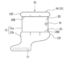
図10は、そのような状態のエアバッグ10を模式的に示す正面図である。
即ち、エアバッグ10は、第三の基布20が取り付けられた部分に対して第三の基布20を挟んだ上下部分がより膨張し易くなっており、図示のように、人が侵入したとき、又は、その前の膨張時において、第三の基布20の上下方向の端部20Bを境界として、エアバッグ10が第三の基布20の外側に向かって膨出(図の膨出部12F)する。この膨出部12Fは、第三の基布20の端部20B付近に沿ってエアバッグ10の表面側基布14の全体に亘って形成され、例えばエアバッグ10の両側面部ではそれぞれエアバッグ10の幅方向外側(図では右側又は左側)に向かって膨出し、エアバッグ10の表側面部ではエアバッグ10の厚さ方向外側(図では紙面の手前側)に向かって膨出する等、表面側基布14の各表面に略直交する方向にそれぞれ膨出する。
FIG. 10 is a front view schematically showing the
That is, in the
このような膨出部12Fの境界部近傍に位置する第三の基布20の端部20Bには、膨出部12F付近の膨張しようとする力により、他の部分に比べて大きなテンション(切断力や破断力等)が作用する。その結果、膨張したエアバッグ10で人を受け止めたときに、切断線又は縫合部(接合部)23が、最もテンションが大きくなる端部20Bから切断し易い等、膨張の境界部が第三の基布20の切断や破断等の起点として作用する。これにより、第三の基布20の切断や破断、又は接合部の接合の外れ等が円滑かつ安定して行われて、ベントホール18の開放が確実かつ迅速化し、衝突した人を安全に保護することができる。
The
なお、第三の基布20の規制力により膨出部12Fを生じさせる他に、エアバッグ10を、予め膨出部12Fが生じ易い形状に形成する、即ち、第三の基布20が取り付けられて膨張が規制される部分に対して、膨張が規制されない端部20B付近から外側部分を、より大きく膨張できるように膨らみを持たせて縫合し(図10参照)、エアバッグ10を形成してもよい。この場合には、エアバッグ10が膨張した状態で膨出部12Fが既にある程度膨出(膨張)しており、エアバッグ10に人が侵入したとき、膨出部12Fがより大きく膨出して第三の基布20に作用するテンションもより大きくなる。このとき、エアバッグ10の膨出部12Fとなる部分を、第三の基布20の端部20よりも内側(中心部側)となる位置から形成した場合には、人が侵入した時の第三の基布20の端部20Bに作用するテンションが更に大きくなるため、第三の基布20の切断や破断等の起点としてより有効に作用する。また、以上の各効果等を得るためには、第三の基布20の端部20B(切断線23の切断端部又は縫合部23の接合端部)の少なくとも一方を、膨張状態のエアバッグ10の第三の基布20に人が侵入したときに、エアバッグ10の第三の基布20により膨張が規制される部分と、これに隣接する膨張が規制されないより大きく膨張する部分(膨張部12F)との境界部近傍に位置するように設ければよい。
In addition to causing the bulging
また、以上で説明した各実施形態に係るエアバッグは、表面側基布14にベントホール18を1つ備えているが、これに限らず、この第1のベントホール18に対してこれから間隔を隔てた適宜の位置に第2のベントホールを設けることもできる。このようにすることで、例えば、エアバッグへの侵入時に身体で一方のベントホールを押さえ込んだとしても、第三の基布20が切断したり或いは結合部が外れることで他方のベントホールからガスを逃がし、侵入時に発生する過大なガス圧を安全なレベルまで低減することができる。なお、このような構成を採る場合は、エアバッグへの侵入時に両方のベントホールが開放されることが起きるため、底付きが生じないように内部テザーを多く配置したり、或いはベントホールの排出能力を制限するなどの措置を講じることがのぞましい。
Moreover, although the airbag which concerns on each embodiment demonstrated above is equipped with one
また、図11に示すように、フロントウインドウ5おける両側のフロントピラー6の前方およびその近辺のフロントガラス5aの前方を、別体のエアバッグ10で覆うようになっているものとして説明したが、これと別の形態として、ピラー部12aがフロントガラス5aの全体を覆うような幅広い構造のものにして、ボンネット3の中央部に1個のエアバッグ装置1を設置する構造にすることもできる。
Further, as shown in FIG. 11, the front of the
以上説明したように、本発明の各実施形態のエアバッグ10は、人がエアバッグ10に衝突したタイミングでベントホール18からのガスの排出を開始するから、人の衝突前においてはエアバッグ10の圧力は高く、人の衝突後の圧力は確実に減圧されるため、人がエアバッグ10に衝突することにより損傷を受けることは無く、二次衝突を防止できるから安全性が高い。また、その構成は、基本的にはエアバッグ10に対して第三の基布20を追加するだけの簡易な構成であるから製造コストも低減可能である。
更に、以上の説明では本エアバッグ装置が歩行者を保護対象とする場合について説明したが、本発明はこれに限ることものではなく、車両の乗員を保護対象とするエアバッグ装置にも当然適用可能である。
As described above, since the
Further, in the above description, the case where the airbag apparatus targets a pedestrian is described. However, the present invention is not limited to this and is naturally applicable to an airbag apparatus that protects a vehicle occupant. Is possible.
1・・・エアバッグ装置、2・・・車両、3・・・ボンネット、5・・・フロントウインドウ、10・・・エアバッグ、11・・・インフレータ、12・・・エアバッグ本体、13・・・内部テザー、16・・・縫合部、18・・・ベントホール、20・・・第三の基布、21・・・第四の基布、23・・・切断線。
DESCRIPTION OF
Claims (7)
前記エアバッグの表面側基布に排気用ベントホールを設け、
前記エアバッグの膨張時に、前記表面側基布に当接して前記排気用ベントホールを覆う部分と前記内部テザーで膨張が規制された前記表面側基布との間に空間を形成する部分とを備えた第三の基布の両側部を、前記表面側基布に糸で縫合し、前記エアバッグの膨張状態において、該エアバッグの前記第三の基布に人が侵入することにより、該エアバッグの膨張で前記第三の基布の一方の端部を縫合する糸が切れて前記表面側基布から外して前記排気用ベントホールを開放することを特徴とするエアバッグ装置。 An airbag device comprising an airbag made of a front side fabric and a back side fabric that are inflated by gas generated from an inflator, and an internal tether that regulates inflation of the airbag,
An exhaust vent hole is provided on the surface side fabric of the airbag,
When the airbag is inflated, a portion that abuts on the surface side fabric and covers the exhaust vent hole and a portion that forms a space between the surface side fabric that is regulated by the internal tether. When both sides of the third base fabric provided are sewn to the surface side base fabric with a thread, and when a person enters the third base fabric of the airbag in the inflated state of the airbag, An airbag device, wherein a thread for stitching one end of the third base fabric is cut by inflation of the airbag and is removed from the surface side base fabric to open the exhaust vent hole.
前記第三の基布の縫合側部の少なくとも一方の端部を、前記膨張状態のエアバッグの前記第三の基布に人が侵入したときに、該エアバッグの前記第三の基布により膨張が規制される部分と、これに隣接する膨張が規制されない部分との境界部近傍に設けたことを特徴とするエアバッグ装置。 In the airbag apparatus described in Claim 1,
When a person intrudes at least one end of the stitching side portion of the third base fabric into the third base fabric of the inflated airbag, the third base fabric of the airbag An airbag device provided in the vicinity of a boundary portion between a portion where inflation is restricted and a portion adjacent to the portion where inflation is not restricted.
前記エアバッグの内部を複数列の内部テザーで区画したことを特徴とするエアバッグ装置。 In the airbag apparatus described in Claim 1 or 2,
An airbag apparatus characterized in that the interior of the airbag is partitioned by a plurality of rows of internal tethers.
前記表面側基布に前記排気用ベントホールに間隔を隔てて設けられ、前記エアバッグの膨張時に前記第三の基布で閉鎖される第2のベントホールが設けられていることを特徴とするエアバッグ装置。 In the airbag apparatus as described in any one of Claim 1 thru | or 3,
The surface-side base cloth is provided with a second vent hole provided at a distance from the exhaust vent hole and closed by the third base cloth when the airbag is inflated. Airbag device.
前記第三の基布の長さは前記エアバッグの膨張時に該エアバッグの膨張によるテンションが作用しない長さであることを特徴とするエアバッグ装置。 In the airbag apparatus as described in any one of Claim 1 thru | or 4,
The length of said 3rd base fabric is a length which is a length which the tension | tensile_strength by expansion | swelling of this airbag does not act at the time of expansion | swelling of the said airbag.
前記エアバッグの裏面側基布に、前記エアバッグの膨張時に該エアバッグの裏面側の横方向への膨張を規制する第四の基布を設けたことを特徴とするエアバッグ装置。 In the airbag apparatus as described in any one of Claim 1 thru | or 5,
An airbag device comprising a back base fabric of the airbag provided with a fourth base fabric that restricts lateral expansion of the back side of the airbag when the airbag is inflated.
車両のボンネットの後端縁に沿う開口より展開することを特徴とするエアバッグ装置。
In the airbag apparatus described in any one of Claims 1 thru | or 6,
An airbag device that is deployed from an opening along a rear end edge of a hood of a vehicle.
Priority Applications (7)
| Application Number | Priority Date | Filing Date | Title |
|---|---|---|---|
| JP2006218769A JP5138191B2 (en) | 2006-02-27 | 2006-08-10 | Airbag device |
| US12/280,762 US7997614B2 (en) | 2006-02-27 | 2007-02-26 | Airbag device |
| CN2007800067654A CN101389510B (en) | 2006-02-27 | 2007-02-26 | Airbag device |
| EP07737383A EP1997695B1 (en) | 2006-02-27 | 2007-02-26 | Airbag device |
| PCT/JP2007/053531 WO2007099912A1 (en) | 2006-02-27 | 2007-02-26 | Airbag device |
| DE602007011226T DE602007011226D1 (en) | 2006-02-27 | 2007-02-26 | AIRBAG DEVICE |
| US13/177,069 US8141902B2 (en) | 2006-02-27 | 2011-07-06 | Airbag device |
Applications Claiming Priority (3)
| Application Number | Priority Date | Filing Date | Title |
|---|---|---|---|
| JP2006051329 | 2006-02-27 | ||
| JP2006051329 | 2006-02-27 | ||
| JP2006218769A JP5138191B2 (en) | 2006-02-27 | 2006-08-10 | Airbag device |
Related Child Applications (1)
| Application Number | Title | Priority Date | Filing Date |
|---|---|---|---|
| JP2012195207A Division JP5361016B2 (en) | 2006-02-27 | 2012-09-05 | Airbag device |
Publications (2)
| Publication Number | Publication Date |
|---|---|
| JP2007253923A JP2007253923A (en) | 2007-10-04 |
| JP5138191B2 true JP5138191B2 (en) | 2013-02-06 |
Family
ID=38628577
Family Applications (1)
| Application Number | Title | Priority Date | Filing Date |
|---|---|---|---|
| JP2006218769A Expired - Fee Related JP5138191B2 (en) | 2006-02-27 | 2006-08-10 | Airbag device |
Country Status (1)
| Country | Link |
|---|---|
| JP (1) | JP5138191B2 (en) |
Cited By (1)
| Publication number | Priority date | Publication date | Assignee | Title |
|---|---|---|---|---|
| JP2012232748A (en) * | 2006-02-27 | 2012-11-29 | Mazda Motor Corp | Airbag device |
Families Citing this family (3)
| Publication number | Priority date | Publication date | Assignee | Title |
|---|---|---|---|---|
| WO2011089720A1 (en) * | 2010-01-22 | 2011-07-28 | トヨタ自動車株式会社 | Pedestrian protection airbag device |
| DE102011119564A1 (en) * | 2011-11-26 | 2013-05-29 | GM Global Technology Operations LLC (n. d. Gesetzen des Staates Delaware) | Airbag for a pedestrian protection system and thus equipped motor vehicle |
| JP2014051152A (en) * | 2012-09-06 | 2014-03-20 | Seiren Co Ltd | Occupant-protecting air bag |
Family Cites Families (2)
| Publication number | Priority date | Publication date | Assignee | Title |
|---|---|---|---|---|
| JP4013661B2 (en) * | 2002-06-14 | 2007-11-28 | タカタ株式会社 | Outer surface deployment type airbag and outer surface deployment type airbag device |
| JP3777362B2 (en) * | 2003-04-15 | 2006-05-24 | 本田技研工業株式会社 | Airbag device |
-
2006
- 2006-08-10 JP JP2006218769A patent/JP5138191B2/en not_active Expired - Fee Related
Cited By (1)
| Publication number | Priority date | Publication date | Assignee | Title |
|---|---|---|---|---|
| JP2012232748A (en) * | 2006-02-27 | 2012-11-29 | Mazda Motor Corp | Airbag device |
Also Published As
| Publication number | Publication date |
|---|---|
| JP2007253923A (en) | 2007-10-04 |
Similar Documents
| Publication | Publication Date | Title |
|---|---|---|
| EP1997695B1 (en) | Airbag device | |
| US9539978B2 (en) | Curtain airbag for a vehicle | |
| US9744936B2 (en) | Curtain airbag for a vehicle and a restraining arrangement | |
| CN110293929B (en) | Airbag device | |
| JP2011057143A (en) | Side airbag device | |
| CN107933483A (en) | Vehicle curtain airbag apparatus | |
| JP5829288B2 (en) | Pedestrian protection airbag for vehicles | |
| US8888128B1 (en) | Airbag for vehicle | |
| US9283918B2 (en) | Curtain airbag | |
| JP5138191B2 (en) | Airbag device | |
| JP5361016B2 (en) | Airbag device | |
| KR101542851B1 (en) | Airbag of vehicle | |
| JP5483586B2 (en) | Airbag device | |
| KR20100059563A (en) | Seatback airbag interlocked with active headrest | |
| US8505970B2 (en) | Airbag cushion for vehicles | |
| JP4969944B2 (en) | Airbag device | |
| EP4177116A1 (en) | Airbag device for pedestrian | |
| JP4460503B2 (en) | Collision protection device | |
| KR101283695B1 (en) | Air-bag cushion | |
| JP6810264B2 (en) | Side airbag device | |
| KR100977598B1 (en) | Inflation shock alleviation airbag device | |
| KR100778589B1 (en) | Car Driver Airbag | |
| KR100788189B1 (en) | Car passenger airbag module and folding method | |
| EP4410607A1 (en) | Passenger seat airbag device | |
| KR20100099550A (en) | Passenger air-bag for a vehicle |
Legal Events
| Date | Code | Title | Description |
|---|---|---|---|
| A621 | Written request for application examination |
Free format text: JAPANESE INTERMEDIATE CODE: A621 Effective date: 20090610 |
|
| A131 | Notification of reasons for refusal |
Free format text: JAPANESE INTERMEDIATE CODE: A131 Effective date: 20120323 |
|
| A521 | Request for written amendment filed |
Free format text: JAPANESE INTERMEDIATE CODE: A523 Effective date: 20120517 |
|
| A02 | Decision of refusal |
Free format text: JAPANESE INTERMEDIATE CODE: A02 Effective date: 20120605 |
|
| A521 | Request for written amendment filed |
Free format text: JAPANESE INTERMEDIATE CODE: A523 Effective date: 20120905 |
|
| A911 | Transfer to examiner for re-examination before appeal (zenchi) |
Free format text: JAPANESE INTERMEDIATE CODE: A911 Effective date: 20120912 |
|
| TRDD | Decision of grant or rejection written | ||
| A01 | Written decision to grant a patent or to grant a registration (utility model) |
Free format text: JAPANESE INTERMEDIATE CODE: A01 Effective date: 20121017 |
|
| A01 | Written decision to grant a patent or to grant a registration (utility model) |
Free format text: JAPANESE INTERMEDIATE CODE: A01 |
|
| A61 | First payment of annual fees (during grant procedure) |
Free format text: JAPANESE INTERMEDIATE CODE: A61 Effective date: 20121114 |
|
| R150 | Certificate of patent or registration of utility model |
Ref document number: 5138191 Country of ref document: JP Free format text: JAPANESE INTERMEDIATE CODE: R150 Free format text: JAPANESE INTERMEDIATE CODE: R150 |
|
| FPAY | Renewal fee payment (event date is renewal date of database) |
Free format text: PAYMENT UNTIL: 20151122 Year of fee payment: 3 |
|
| R250 | Receipt of annual fees |
Free format text: JAPANESE INTERMEDIATE CODE: R250 |
|
| R250 | Receipt of annual fees |
Free format text: JAPANESE INTERMEDIATE CODE: R250 |
|
| R250 | Receipt of annual fees |
Free format text: JAPANESE INTERMEDIATE CODE: R250 |
|
| R250 | Receipt of annual fees |
Free format text: JAPANESE INTERMEDIATE CODE: R250 |
|
| LAPS | Cancellation because of no payment of annual fees |