JP5126388B2 - Gas sensor control device - Google Patents
Gas sensor control device Download PDFInfo
- Publication number
- JP5126388B2 JP5126388B2 JP2011117453A JP2011117453A JP5126388B2 JP 5126388 B2 JP5126388 B2 JP 5126388B2 JP 2011117453 A JP2011117453 A JP 2011117453A JP 2011117453 A JP2011117453 A JP 2011117453A JP 5126388 B2 JP5126388 B2 JP 5126388B2
- Authority
- JP
- Japan
- Prior art keywords
- sensor
- constant current
- change
- rich
- lean
- Prior art date
- Legal status (The legal status is an assumption and is not a legal conclusion. Google has not performed a legal analysis and makes no representation as to the accuracy of the status listed.)
- Active
Links
- 238000001514 detection method Methods 0.000 claims description 204
- 239000007789 gas Substances 0.000 claims description 200
- 239000000446 fuel Substances 0.000 claims description 166
- 230000008859 change Effects 0.000 claims description 162
- 230000004044 response Effects 0.000 claims description 120
- 230000004043 responsiveness Effects 0.000 claims description 74
- 238000012508 change request Methods 0.000 claims description 57
- 239000001301 oxygen Substances 0.000 claims description 53
- 229910052760 oxygen Inorganic materials 0.000 claims description 53
- QVGXLLKOCUKJST-UHFFFAOYSA-N atomic oxygen Chemical compound [O] QVGXLLKOCUKJST-UHFFFAOYSA-N 0.000 claims description 52
- 238000002485 combustion reaction Methods 0.000 claims description 39
- 239000007784 solid electrolyte Substances 0.000 claims description 39
- 230000001965 increasing effect Effects 0.000 claims description 29
- 230000001052 transient effect Effects 0.000 claims description 18
- 230000002708 enhancing effect Effects 0.000 claims description 2
- 239000010410 layer Substances 0.000 description 81
- 239000003054 catalyst Substances 0.000 description 38
- 238000002347 injection Methods 0.000 description 26
- 239000007924 injection Substances 0.000 description 26
- 238000000034 method Methods 0.000 description 14
- 230000008569 process Effects 0.000 description 13
- 238000011144 upstream manufacturing Methods 0.000 description 13
- 230000035945 sensitivity Effects 0.000 description 10
- 238000006243 chemical reaction Methods 0.000 description 6
- 239000000203 mixture Substances 0.000 description 6
- 230000001133 acceleration Effects 0.000 description 5
- 230000007423 decrease Effects 0.000 description 5
- 230000003247 decreasing effect Effects 0.000 description 5
- 230000003111 delayed effect Effects 0.000 description 5
- 230000006866 deterioration Effects 0.000 description 5
- 238000010586 diagram Methods 0.000 description 5
- 230000000694 effects Effects 0.000 description 5
- 238000005516 engineering process Methods 0.000 description 5
- 238000013461 design Methods 0.000 description 4
- 230000007935 neutral effect Effects 0.000 description 4
- 238000006722 reduction reaction Methods 0.000 description 4
- 230000007704 transition Effects 0.000 description 4
- 238000000746 purification Methods 0.000 description 3
- 230000009467 reduction Effects 0.000 description 3
- MCMNRKCIXSYSNV-UHFFFAOYSA-N Zirconium dioxide Chemical compound O=[Zr]=O MCMNRKCIXSYSNV-UHFFFAOYSA-N 0.000 description 2
- WMWLMWRWZQELOS-UHFFFAOYSA-N bismuth(iii) oxide Chemical compound O=[Bi]O[Bi]=O WMWLMWRWZQELOS-UHFFFAOYSA-N 0.000 description 2
- 239000000498 cooling water Substances 0.000 description 2
- 238000011156 evaluation Methods 0.000 description 2
- 230000020169 heat generation Effects 0.000 description 2
- 230000006872 improvement Effects 0.000 description 2
- 239000004615 ingredient Substances 0.000 description 2
- 238000007562 laser obscuration time method Methods 0.000 description 2
- 239000010687 lubricating oil Substances 0.000 description 2
- 238000005259 measurement Methods 0.000 description 2
- 238000006386 neutralization reaction Methods 0.000 description 2
- 239000003921 oil Substances 0.000 description 2
- BASFCYQUMIYNBI-UHFFFAOYSA-N platinum Chemical compound [Pt] BASFCYQUMIYNBI-UHFFFAOYSA-N 0.000 description 2
- 229910004369 ThO2 Inorganic materials 0.000 description 1
- 230000004913 activation Effects 0.000 description 1
- PNEYBMLMFCGWSK-UHFFFAOYSA-N aluminium oxide Inorganic materials [O-2].[O-2].[O-2].[Al+3].[Al+3] PNEYBMLMFCGWSK-UHFFFAOYSA-N 0.000 description 1
- 230000003197 catalytic effect Effects 0.000 description 1
- 239000000919 ceramic Substances 0.000 description 1
- 238000007796 conventional method Methods 0.000 description 1
- 238000002474 experimental method Methods 0.000 description 1
- CJNBYAVZURUTKZ-UHFFFAOYSA-N hafnium(IV) oxide Inorganic materials O=[Hf]=O CJNBYAVZURUTKZ-UHFFFAOYSA-N 0.000 description 1
- 238000010438 heat treatment Methods 0.000 description 1
- 238000004519 manufacturing process Methods 0.000 description 1
- 230000003472 neutralizing effect Effects 0.000 description 1
- 229910000510 noble metal Inorganic materials 0.000 description 1
- 238000007254 oxidation reaction Methods 0.000 description 1
- 229910002077 partially stabilized zirconia Inorganic materials 0.000 description 1
- 238000007747 plating Methods 0.000 description 1
- 229910052697 platinum Inorganic materials 0.000 description 1
- 238000002360 preparation method Methods 0.000 description 1
- 238000012545 processing Methods 0.000 description 1
- 230000002250 progressing effect Effects 0.000 description 1
- 239000011241 protective layer Substances 0.000 description 1
- 238000005086 pumping Methods 0.000 description 1
- 230000002441 reversible effect Effects 0.000 description 1
- 239000003381 stabilizer Substances 0.000 description 1
- 239000000126 substance Substances 0.000 description 1
- ZCUFMDLYAMJYST-UHFFFAOYSA-N thorium dioxide Chemical compound O=[Th]=O ZCUFMDLYAMJYST-UHFFFAOYSA-N 0.000 description 1
- XLYOFNOQVPJJNP-UHFFFAOYSA-N water Substances O XLYOFNOQVPJJNP-UHFFFAOYSA-N 0.000 description 1
- FIXNOXLJNSSSLJ-UHFFFAOYSA-N ytterbium(III) oxide Inorganic materials O=[Yb]O[Yb]=O FIXNOXLJNSSSLJ-UHFFFAOYSA-N 0.000 description 1
Images


Classifications
-
- G—PHYSICS
- G01—MEASURING; TESTING
- G01N—INVESTIGATING OR ANALYSING MATERIALS BY DETERMINING THEIR CHEMICAL OR PHYSICAL PROPERTIES
- G01N27/00—Investigating or analysing materials by the use of electric, electrochemical, or magnetic means
- G01N27/26—Investigating or analysing materials by the use of electric, electrochemical, or magnetic means by investigating electrochemical variables; by using electrolysis or electrophoresis
- G01N27/403—Cells and electrode assemblies
- G01N27/406—Cells and probes with solid electrolytes
- G01N27/407—Cells and probes with solid electrolytes for investigating or analysing gases
- G01N27/409—Oxygen concentration cells
Landscapes
- Chemical & Material Sciences (AREA)
- Life Sciences & Earth Sciences (AREA)
- Health & Medical Sciences (AREA)
- Biochemistry (AREA)
- Chemical Kinetics & Catalysis (AREA)
- Electrochemistry (AREA)
- Physics & Mathematics (AREA)
- Analytical Chemistry (AREA)
- Molecular Biology (AREA)
- General Health & Medical Sciences (AREA)
- General Physics & Mathematics (AREA)
- Immunology (AREA)
- Pathology (AREA)
- Combined Controls Of Internal Combustion Engines (AREA)
- Electrical Control Of Air Or Fuel Supplied To Internal-Combustion Engine (AREA)
- Measuring Oxygen Concentration In Cells (AREA)
Description
本発明は、ガスセンサ制御装置に関するものである。 The present invention relates to a gas sensor control device.
例えば、車両用エンジンでは、同エンジンから排出される排気を検出対象として酸素濃度を検出するガスセンサが一般に用いられている。排気を検出対象とするガスセンサは、例えば排気がリッチかリーンかで異なる電気信号を出力するものとなっており、起電力出力型のO2センサの場合、空燃比がリッチであれば約0.9Vの起電力信号を出力し、空燃比がリーンであれば約0Vの起電力信号を出力する。 For example, in a vehicle engine, a gas sensor that detects an oxygen concentration using exhaust gas discharged from the engine as a detection target is generally used. The gas sensor for detecting exhaust gas outputs, for example, different electrical signals depending on whether the exhaust gas is rich or lean. In the case of an electromotive force output type O2 sensor, if the air-fuel ratio is rich, about 0.9V If the air-fuel ratio is lean, an electromotive force signal of about 0 V is output.
ここで、既存の実用化技術では、排気の空燃比がリッチ/リーンで変化する際に、実際の空燃比変化に対してセンサ出力が遅れを伴い変化するのが実状であり、ガスセンサにおいては検出応答性の点で改善の余地があると考えられる。 Here, in the existing practical technology, when the air-fuel ratio of the exhaust changes rich / lean, the actual condition is that the sensor output changes with a delay with respect to the actual air-fuel ratio change. There is room for improvement in terms of responsiveness.
この種の技術に関して、例えば、特許文献1に記載されているガスセンサでは、起電力O2センサの基本構造に対して、少なくとも1つの補助電気化学電池を備える構成としている。この場合、補助電気化学電池はO2センサの一方の電極に接続されており、補助電気化学電池に印加電流を与えることでイオンポンピングを行い、それにより被測定ガスの濃度を変化させるようにしている。これにより、印加電流に応じてλ特性をシフトさせることが可能となっている。
With regard to this type of technology, for example, the gas sensor described in
しかしながら、特許文献1の発明では、補助電気化学電池を備えていない一般的なO2センサに対してセンサ構造を大きく変更する必要があり、実用化にあたっては、O2センサの設計変更が強いられたり、O2センサの製造コストが嵩んだりする等の不都合が生じる。
However, in the invention of
本発明は、簡易な構成を用いつつも、検出応答性等のガスセンサの出力特性を好適に調整することができるガスセンサ制御装置を提供することを主たる目的とするものである。 The main object of the present invention is to provide a gas sensor control device that can suitably adjust the output characteristics of a gas sensor such as detection responsiveness while using a simple configuration.
以下、上記課題を解決するための手段、及びその作用効果について説明する。 Hereinafter, means for solving the above-described problems and the effects thereof will be described.
第1の発明のガスセンサ制御装置は、固体電解質体と該固体電解質体の表面に設けられた一対のセンサ電極とを有するガスセンサに適用され、センサ検出対象となる被検出ガスに含まれる所定ガス成分の濃度を前記ガスセンサの検出信号に基づいて演算する。そして、前記一対のセンサ電極の少なくともいずれかに電気的に接続され、その接続されたセンサ電極に対して定電流を供給する定電流供給手段と、前記所定ガス成分の濃度変化に対する検出応答性を含む前記ガスセンサの出力特性を変更する変更要求の有無を判定する判定手段と、前記判定手段により前記変更要求が有ると判定された場合に、その変更要求に基づいて、前記一対のセンサ電極間に流れる定電流の向きを決定し、該決定した向きで前記定電流が流れるように前記定電流供給手段を制御する電流制御手段と、を備える。 A gas sensor control device according to a first aspect of the present invention is applied to a gas sensor having a solid electrolyte body and a pair of sensor electrodes provided on the surface of the solid electrolyte body, and a predetermined gas component contained in a gas to be detected as a sensor detection target. Is calculated based on the detection signal of the gas sensor. And a constant current supply means that is electrically connected to at least one of the pair of sensor electrodes and supplies a constant current to the connected sensor electrodes; and a detection responsiveness to a change in the concentration of the predetermined gas component. Determining means for determining whether or not there is a change request for changing the output characteristics of the gas sensor, and when the determination means determines that there is the change request, based on the change request, between the pair of sensor electrodes Current control means for determining the direction of the flowing constant current and controlling the constant current supply means so that the constant current flows in the determined direction.
被検出ガスにおいて所定ガス成分の濃度変化が生じる際(被検出ガスの成分組成が変わる場合を含む)において、その濃度変化が実際に生じても、濃度変化前のガス組成に含まれるガス成分がセンサ周りに残っていると、新たなガス組成に含まれるガス成分の検出に対してセンサ検出信号の出力変化(すなわちセンサ応答性)が遅くなる。また、こうしたセンサ応答性の低下について、対処すべき内容は都度変わり得ると考えられる。 When the concentration change of the predetermined gas component occurs in the detected gas (including the case where the component composition of the detected gas changes), even if the concentration change actually occurs, the gas component contained in the gas composition before the concentration change If it remains around the sensor, the change in the output of the sensor detection signal (that is, the sensor response) is delayed with respect to the detection of the gas component contained in the new gas composition. In addition, it is considered that the content to be dealt with for such a decrease in sensor responsiveness may change from time to time.
この点、本発明では、検出応答性を含むガスセンサの出力特性を変更すべき状況下であることを判定するとともに、その状況下において、都度の状況(変更要求)に基づいて、一対のセンサ電極間に流れる定電流の向きを決定し、その決定した向きで定電流を供給することとした。そのため、所定ガス成分の濃度変化に際し、本来検出したい所定ガス成分とは異なる成分(濃度検出に邪魔になる成分)についてその除去を早めたり、それとは逆に遅くしたりすることができる。かかる場合、所定ガス成分の濃度変化後において本来検出したい所定ガス成分に対する検出応答性を任意に調整することが可能となる。また、濃度変化が生じない場合にあっても、本来検出したい所定ガス成分とは異なる成分(濃度検出に邪魔になる成分)についてその除去を促したり、それとは逆に抑えたりすることができ、ガスセンサの出力特性(出力値)自体を変更することが可能となる。ここで本発明では、ガスセンサの出力特性を変更するための構成として、定電流供給手段によりガスセンサに定電流を供給する構成を採用しているため、ガスセンサ自体の設計変更等が強いられるものではなく、構成の煩雑化を抑制できる。以上により、簡易な構成を用いつつも、ガスセンサの出力特性を好適に調整することができるものとなる。 In this regard, in the present invention, it is determined that the output characteristics of the gas sensor including the detection responsiveness should be changed, and a pair of sensor electrodes is determined based on the situation (change request) in each situation. The direction of the constant current flowing between them was determined, and the constant current was supplied in the determined direction. For this reason, when the concentration of the predetermined gas component is changed, it is possible to accelerate the removal of a component different from the predetermined gas component to be originally detected (a component that interferes with the concentration detection), or to conversely delay the removal. In such a case, it is possible to arbitrarily adjust the detection responsiveness to the predetermined gas component to be originally detected after the concentration change of the predetermined gas component. In addition, even when the concentration does not change, it is possible to promote the removal of components that are different from the predetermined gas components that are originally desired to detect (components that interfere with the concentration detection), or to suppress them. It becomes possible to change the output characteristics (output value) itself of the gas sensor. Here, in the present invention, as a configuration for changing the output characteristics of the gas sensor, a configuration in which a constant current is supplied to the gas sensor by the constant current supply means is adopted, so that the design change of the gas sensor itself is not forced. Therefore, complication of the configuration can be suppressed. As described above, the output characteristics of the gas sensor can be suitably adjusted while using a simple configuration.
第2の発明は、内燃機関の排気を被検出ガスとして空燃比を検出するガスセンサに適用される。そして、前記判定手段は、空燃比がリッチからリーンに変化するリーン変化時の前記ガスセンサの出力特性、及び空燃比がリーンからリッチに変化するリッチ変化時の前記ガスセンサの出力特性の少なくともいずれかについて、前記変更要求の有無を判定するものであり、前記電流制御手段は、前記リーン変化時の出力特性及び前記リッチ変化時の出力特性に関する前記判定手段の判定結果に基づいて、前記一対のセンサ電極間に流れる定電流の向きを決定する。 The second invention is applied to a gas sensor that detects an air-fuel ratio using the exhaust gas of an internal combustion engine as a detected gas. The determination unit is configured to output at least one of an output characteristic of the gas sensor at the time of lean change when the air-fuel ratio changes from rich to lean and an output characteristic of the gas sensor at the time of rich change where the air-fuel ratio changes from lean to rich. Determining whether or not there is a change request, wherein the current control means is configured to determine the output characteristics at the time of the lean change and the determination results of the determination means regarding the output characteristics at the time of the rich change. The direction of the constant current flowing between them is determined.
内燃機関から排出される排気の場合、空燃比についてリッチ/リーンの変化(切り替わり)が生じる。この場合、空燃比がリッチからリーンに変化する際(リーン変化時)には、リーンへの変化直後においてリッチ成分であるHC等がセンサ周りに残留し、このリッチ成分により、センサ電極でのリーン成分(NOx等)の検出反応が妨げられる。その結果、ガスセンサにおいてリーン出力の応答性が低下する。また、空燃比がリーンからリッチに変化する際(リッチ変化時)には、リッチへの変化直後においてリーン成分であるNOx等がセンサ周りに残留し、このリーン成分により、センサ電極でのリッチ成分(HC等)の検出反応が妨げられる。その結果、ガスセンサにおいてリッチ出力の応答性が低下する。 In the case of exhaust discharged from an internal combustion engine, a rich / lean change (switching) occurs in the air-fuel ratio. In this case, when the air-fuel ratio changes from rich to lean (at the time of lean change), HC or the like, which is a rich component, remains around the sensor immediately after the change to lean, and this rich component causes the lean at the sensor electrode. Detection reaction of components (NOx, etc.) is hindered. As a result, the responsiveness of the lean output decreases in the gas sensor. Further, when the air-fuel ratio changes from lean to rich (during rich change), NOx, which is a lean component, remains around the sensor immediately after the change to rich, and this lean component causes a rich component at the sensor electrode. Detection reaction of (HC etc.) is hindered. As a result, the rich output response in the gas sensor is reduced.
この点、第2の発明では、ガスセンサについてリーン変化時の出力特性やリッチ変化時の出力特性を変更するか否かを判定しており、その判定結果に基づいて、一対のセンサ電極間に流れる定電流の向きを決定するため、それら空燃比の変化時においてガスセンサの出力特性(検出応答性)を所望の特性に調整することが可能となる。 In this regard, in the second invention, it is determined whether or not to change the output characteristic at the time of lean change or the output characteristic at the time of rich change for the gas sensor, and based on the determination result, the gas sensor flows between the pair of sensor electrodes. Since the direction of the constant current is determined, it is possible to adjust the output characteristics (detection responsiveness) of the gas sensor to desired characteristics when the air-fuel ratio changes.
なお、上記のとおり一対のセンサ電極間に定電流を流すことでガスセンサの出力特性を変更する構成では、リッチ/リーンの変化時だけでなく、空燃比がリーンになっている状態、リッチになっている状態でも、ガスセンサの出力特性(出力値)が変更できるものとなっている(図7参照)。この場合、リーン感度及びリッチ感度のいずれかが向上するものとなっている。 In the configuration in which the output characteristics of the gas sensor are changed by passing a constant current between the pair of sensor electrodes as described above, the air-fuel ratio becomes lean not only when the rich / lean changes but also when the air-fuel ratio is lean. Even in this state, the output characteristic (output value) of the gas sensor can be changed (see FIG. 7). In this case, either the lean sensitivity or the rich sensitivity is improved.
定電流の供給に関して具体的には、第3の発明のように、前記判定手段により前記リーン変化時の出力特性として同変化時の検出応答性を高める変更要求が有ると判定された場合に、前記固体電解質体を通じて基準室側電極から排気側電極に酸素が供給される向きに定電流が流れるように前記定電流供給手段を制御し、前記判定手段により前記リッチ変化時の出力特性として同変化時の検出応答性を高める変更要求が有ると判定された場合に、前記固体電解質体を通じて排気側電極から基準室側電極に酸素が供給される向きに定電流が流れるように前記定電流供給手段を制御するとよい。 Specifically, as for the supply of constant current, as in the third invention, when it is determined by the determination means that there is a change request for improving the detection response at the time of the change as the output characteristic at the time of the lean change, The constant current supply means is controlled so that a constant current flows in a direction in which oxygen is supplied from the reference chamber side electrode to the exhaust side electrode through the solid electrolyte body, and the same change is made as an output characteristic at the rich change time by the determination means. The constant current supply means so that a constant current flows in a direction in which oxygen is supplied from the exhaust side electrode to the reference chamber side electrode through the solid electrolyte body when it is determined that there is a change request for improving detection response at the time It is good to control.
つまり、リッチ→リーンの変化時に、固体電解質体を通じて基準室側電極から排気側電極に酸素が供給されるようにすることで、排気側電極の周囲に存在(残留)しているリッチ成分(HC等)をいち早く除去し、その結果リーン出力の応答性を向上させることができる。また、リーン→リッチの変化時に、固体電解質体を通じて排気側電極から基準室側電極に酸素が供給されるようにすることで、排気側電極の周囲に存在(残留)しているリーン成分(NOx等)をいち早く除去し、その結果リッチ出力の応答性を向上させることができる。 In other words, when rich to lean, oxygen is supplied from the reference chamber side electrode to the exhaust side electrode through the solid electrolyte body, so that the rich component (HC) that exists (residual) around the exhaust side electrode (HC) Etc.) can be removed quickly, and as a result, the response of the lean output can be improved. In addition, when changing from lean to rich, oxygen is supplied from the exhaust side electrode to the reference chamber side electrode through the solid electrolyte body, so that the lean component (NOx) existing (residual) around the exhaust side electrode is present. Etc.) can be removed quickly, and as a result, the response of rich output can be improved.
また、第4の発明では、前記内燃機関の運転状態を検出する運転状態検出手段を備え、前記判定手段は、前記運転状態検出手段により検出された機関運転状態に基づいて、前記変更要求の有無を判定する。 According to a fourth aspect of the present invention, there is provided an operation state detection unit that detects an operation state of the internal combustion engine, and the determination unit determines whether the change request is present based on the engine operation state detected by the operation state detection unit. Determine.
内燃機関の運転中には、ガスセンサに求められる出力特性(検出応答性)が都度変化すると考えられる。この点、上記構成によれば、時々の機関運転状態に対応させつつ、ガスセンサに対して都度適した出力特性を付与することができる。 During the operation of the internal combustion engine, it is considered that the output characteristics (detection response) required for the gas sensor change every time. In this regard, according to the above-described configuration, it is possible to give an appropriate output characteristic to the gas sensor while corresponding to the engine operating state from time to time.
第5の発明は、前記ガスセンサによる空燃比の検出結果に基づいて、空燃比を所定の目標値に制御する内燃機関制御システムに適用され、前記判定手段は、前記運転状態検出手段により検出された機関運転状態に基づいて前記内燃機関が高負荷運転になっていると判断された場合に、前記リーン変化時の検出応答性を高める変更要求が有ると判定し、前記電流制御手段は、前記リーン変化時の検出応答性を高める変更要求に基づいて前記定電流供給手段を制御する。 The fifth invention is applied to an internal combustion engine control system that controls the air-fuel ratio to a predetermined target value based on the detection result of the air-fuel ratio by the gas sensor, and the determination means is detected by the operating state detection means When it is determined that the internal combustion engine is in a high load operation based on the engine operating state, it is determined that there is a change request for improving the detection response at the time of the lean change, and the current control means The constant current supply means is controlled on the basis of a change request for improving detection response at the time of change.
内燃機関の高負荷運転状態では、気筒内に吸入される新気量が増え、リーン成分(NOx)の排出が増えることが懸念される。この点、上記のとおりリーン変化時におけるガスセンサの検出応答性が高められることにより、空燃比制御においてリーン変化に対して高応答となる制御を実施できる。これにより、高負荷運転状態でのリーン成分(NOx)の排出を抑制できる。 When the internal combustion engine is in a high load operation state, there is a concern that the amount of fresh air taken into the cylinder increases and the emission of lean components (NOx) increases. In this respect, as described above, the detection responsiveness of the gas sensor at the time of the lean change is enhanced, so that the air-fuel ratio control can be performed with a high response to the lean change. Thereby, discharge | emission of the lean component (NOx) in a high load driving | running state can be suppressed.
また、第6の発明は、前記ガスセンサによる空燃比の検出結果に基づいて、空燃比を所定の目標値に制御する内燃機関制御システムに適用され、前記判定手段は、前記運転状態検出手段により検出された機関運転状態に基づいて前記内燃機関が冷間状態になっていると判断された場合に、前記リッチ変化時の検出応答性を高める変更要求が有ると判定し、前記電流制御手段は、前記リッチ変化時の検出応答性を高める変更要求に基づいて前記定電流供給手段を制御する。 The sixth invention is applied to an internal combustion engine control system that controls the air-fuel ratio to a predetermined target value based on the detection result of the air-fuel ratio by the gas sensor, and the determining means is detected by the operating state detecting means. When it is determined that the internal combustion engine is in a cold state based on the engine operating state determined, it is determined that there is a change request to improve the detection response at the time of the rich change, the current control means, The constant current supply means is controlled based on a change request for improving the detection responsiveness during the rich change.
内燃機関の冷間状態では、燃焼室内で燃焼に供される燃料噴射量が増やされ、リッチ成分(HC等)の排出が増えることが懸念される。この点、上記のとおりリッチ変化時におけるガスセンサの検出応答性が高められることにより、空燃比制御においてリッチ変化に対して高応答となる制御を実施できる。これにより、冷間状態でのリッチ成分(HC等)の排出を抑制できる。 In the cold state of the internal combustion engine, there is a concern that the amount of fuel injection provided for combustion in the combustion chamber is increased and the emission of rich components (HC, etc.) is increased. In this regard, as described above, the detection responsiveness of the gas sensor at the time of rich change is enhanced, so that it is possible to perform control that provides high response to the rich change in air-fuel ratio control. Thereby, discharge | emission of rich components (HC etc.) in a cold state can be suppressed.
また、本発明では、ガスセンサの検出応答性を高めるだけでなく、低めることも可能であり、検出応答性を低める構成として以下が考えられる。 In the present invention, not only the detection responsiveness of the gas sensor can be increased but also decreased, and the following can be considered as a configuration for reducing the detection responsiveness.
前記内燃機関の排気通路において排気の上流側と下流側となる位置にそれぞれ設けられた上流側触媒と下流側触媒とを備え、それら両触媒の間に前記ガスセンサが設けられており、前記内燃機関の運転中に燃料カットを実施するとともに、その燃料カットから燃料噴射への復帰時に、前記ガスセンサによる空燃比の検出結果に基づいて、前記両触媒の酸素過多の状態を解消すべく空燃比を一時的にリッチ化するリッチ噴射制御を実施する内燃機関制御システムに適用され、
前記判定手段は、前記リッチ噴射制御を実施する場合に、前記リッチ変化時の検出応答性を低める変更要求が有ると判定し、
前記電流制御手段は、前記リッチ変化時の検出応答性を低める変更要求に基づいて前記定電流供給手段を制御する。
The internal combustion engine includes an upstream catalyst and a downstream catalyst provided at positions upstream and downstream of exhaust in the exhaust passage of the internal combustion engine, respectively, and the gas sensor is provided between the two catalysts. The fuel cut is carried out during the operation of the engine, and at the time of returning from the fuel cut to the fuel injection, the air-fuel ratio is temporarily set to eliminate the excessive oxygen state of the two catalysts based on the detection result of the air-fuel ratio by the gas sensor. Applied to an internal combustion engine control system that performs rich injection control that is enriched
The determination unit determines that there is a change request to lower the detection responsiveness at the time of the rich change when the rich injection control is performed,
The current control means controls the constant current supply means based on a change request for lowering the detection response at the rich change time.
排気通路に上流側触媒と下流側触媒とが設けられている構成において燃料カットが実施されると、それら両触媒が酸素過多の状態(極リーン状態)となり、燃料カットからの復帰直後には、両触媒の酸素過多の状態をいち早く解消させるべく、すなわち両触媒を中立状態(酸素適量状態)にいち早く復帰させるべく、ガスセンサによる空燃比の検出結果に基づいてリッチ噴射制御が実施される。この場合、ガスセンサは両触媒の間に設けられたものであり、そのガスセンサの検出結果がリーンからリッチに変化したことに基づいてリッチ噴射制御が終了される。しかしながら、ガスセンサの設置位置において実空燃比がリーンからリッチに変化した時点では、上流側触媒のみが中立状態となっており、下流側触媒については未だ酸素過多の状態のままであることが考えられる。 When the fuel cut is performed in the configuration in which the upstream side catalyst and the downstream side catalyst are provided in the exhaust passage, both the catalysts become in an excessive oxygen state (extremely lean state), and immediately after returning from the fuel cut, Rich injection control is performed based on the detection result of the air-fuel ratio by the gas sensor in order to quickly eliminate the excessive oxygen state of both catalysts, that is, to quickly return both catalysts to the neutral state (oxygen proper amount state). In this case, the gas sensor is provided between the two catalysts, and the rich injection control is terminated based on the detection result of the gas sensor changing from lean to rich. However, at the time when the actual air-fuel ratio changes from lean to rich at the position where the gas sensor is installed, only the upstream catalyst is in a neutral state, and the downstream catalyst may still be in an excessively oxygen state. .
この点、上記構成では、リッチ噴射制御を実施する場合にリッチ変化時の検出応答性を低める構成としているため、リッチ噴射制御の実施中において実際の空燃比変化(リーン→リッチの変化)に対してガスセンサの出力応答が遅れることとなる。この場合、上流側触媒が中立状態となった後、それから幾分遅れてリッチ噴射制御が終了されることになる。したがって、燃料カット後において、上流側及び下流側の両触媒について適正なる中立化の制御を実施でき、ひいては燃料カット直後における排気浄化を好適に実施できる。 In this regard, in the above configuration, when rich injection control is performed, the detection responsiveness at the time of rich change is reduced. Therefore, the actual air-fuel ratio change (lean → rich change) during the rich injection control is performed. As a result, the output response of the gas sensor is delayed. In this case, after the upstream catalyst is in a neutral state, the rich injection control is terminated with a slight delay. Therefore, after the fuel cut, proper neutralization control can be performed for both the upstream and downstream catalysts, and thus exhaust purification immediately after the fuel cut can be suitably performed.
第7の発明では、前記定電流供給手段は、前記センサ電極間で流れる定電流の量を調整可能であり、前記電流制御手段は、前記判定手段の判定結果に基づいて、前記定電流供給手段による定電流量の調整により前記出力特性として検出応答性の応答性レベルを可変に制御する。 In a seventh invention, the constant current supply means is capable of adjusting an amount of a constant current flowing between the sensor electrodes, and the current control means is based on a determination result of the determination means. The responsiveness level of the detection responsiveness is variably controlled as the output characteristic by adjusting the constant current amount by.
センサ電極間に定電流を流してガスセンサの検出応答性を変更する場合、リーン変化時の検出応答性とリッチ変化時の検出応答性とのうち一方を高める状態にすると、他方が低められることとなる。そのため、リーン変化時及びリッチ変化時のいずれかの検出応答性を高める場合には、その応答性レベルを適度に調整することが望ましい。この点、上記構成によれば、定電流量の調整によりガスセンサの検出応答性の応答性レベルが制御できるため、リーン変化時の検出応答性とリッチ変化時の検出応答性とのバランスを考慮しつつ、検出応答性を可変に制御できる。 When changing the detection responsiveness of a gas sensor by passing a constant current between sensor electrodes, if one of the detection responsiveness at the time of lean change and the detection responsiveness at the time of rich change is made to be in a state where the other is lowered, Become. Therefore, when enhancing the detection responsiveness at either the lean change or the rich change, it is desirable to adjust the responsiveness level appropriately. In this regard, according to the above configuration, the response level of the detection response of the gas sensor can be controlled by adjusting the constant current amount, so that the balance between the detection response at the time of lean change and the detection response at the time of rich change is taken into consideration. Meanwhile, the detection response can be variably controlled.
第8の発明では、前記判定手段は、前記内燃機関の負荷が増加側に変化する過渡時、及びその負荷増加により高負荷となっている高負荷定常時に、前記リーン変化時の検出応答性を高める変更要求が有ると判定し、前記電流制御手段は、前記過渡時の応答性レベルを、前記高負荷定常時の応答性レベルよりも高応答とする。 In an eighth aspect of the invention, the determination means provides detection responsiveness at the time of the lean change at a transient time when the load of the internal combustion engine changes to an increasing side and at a high load steady state when the load increases due to the increase in the load. It is determined that there is a change request to be increased, and the current control unit sets the response level at the time of transition to a higher response than the response level at the time of steady high load.
内燃機関の負荷が増加側に変化する過渡時、及びその負荷増加により高負荷となっている高負荷定常時はいずれも、気筒内に吸入される新気量が増え、NOx等のリーン成分の排出が増えることが懸念されるため、NOx等の排出抑制の観点からすればリーン変化時の検出応答性を高めることが望ましい。ただし、過渡時と高負荷定常時とを比べると、過渡時の方が、NOx等の排出量が意図せず増える懸念が大きい。この点、上記構成によれば、過渡時の応答性レベルを、高負荷定常時の応答性レベルよりも高応答としているため、リーン変化時の検出応答性とリッチ変化時の検出応答性とのバランスを保ちつつ、NOx等のリーン成分の排出を好適に抑制できる。 In both the transient when the load of the internal combustion engine changes to the increasing side and the high load steady state that is high due to the increase in the load, the amount of fresh air drawn into the cylinder increases and the lean component such as NOx Since there is concern about an increase in emissions, it is desirable to improve the detection response at the time of lean change from the viewpoint of suppressing emissions of NOx and the like. However, when comparing the transient state and the high load steady state, there is a greater concern that the amount of NOx and other emissions will increase unintentionally during the transient state. In this regard, according to the above configuration, since the response level at the time of transient is higher than the response level at the time of steady high load, the detection response at the time of lean change and the detection response at the time of rich change While maintaining the balance, the discharge of lean components such as NOx can be suitably suppressed.
(第1の実施形態)
以下、本発明を具体化した第1の実施の形態について図面を参照しつつ説明する。本実施形態は、車載エンジンの排気管に設けられたガスセンサを用い、そのガスセンサの出力に基づいてエンジンの各種制御等を実施するエンジン制御システムについて説明する。当該制御システムにおいては、電子制御ユニット(以下、ECUという)を中枢として燃料噴射量の制御や点火時期の制御等を実施する。図1は、本システムの全体概要を示す構成図である。
(First embodiment)
Hereinafter, a first embodiment of the present invention will be described with reference to the drawings. In the present embodiment, an engine control system that uses a gas sensor provided in an exhaust pipe of an in-vehicle engine and performs various controls of the engine based on the output of the gas sensor will be described. In this control system, an electronic control unit (hereinafter referred to as ECU) is used as a center to control the fuel injection amount, control the ignition timing, and the like. FIG. 1 is a configuration diagram showing an overall outline of the present system.
図1において、エンジン10は、例えばガソリンエンジンであり、電子制御式のスロットルバルブ11や、燃料噴射弁12、点火装置13等を備えている。エンジン10の排気管14(排気通路)には排気浄化装置としての触媒15a,15bが設けられている。触媒15a,15bは、例えばいずれも三元触媒よりなり、そのうち触媒15aが上流側触媒としての第1触媒、触媒15bが下流側触媒としての第2触媒である。第1触媒15aの上流側にはA/Fセンサ16が設けられ、触媒15a,15bの間(第1触媒15aの下流側でかつ第2触媒15bの上流側)にはO2センサ17が設けられている。A/Fセンサ16は、排気の空燃比に略比例するA/F信号を出力する。また、O2センサ17は、排気の空燃比がリッチかリーンかに応じて異なる起電力信号を出力する。
In FIG. 1, an
その他、本システムには、スロットルバルブ11の開度を検出するスロットル開度センサ21や、エンジンの所定クランク角毎に(例えば30°CA周期で)矩形状のクランク角信号を出力するクランク角センサ22、エンジン10の吸入空気量を検出する空気量センサ23、エンジン冷却水の温度を検出する冷却水温センサ24等の各種センサが設けられている。図示は省略するが、上記以外に、気筒内の燃焼圧を検出する燃焼圧センサ、アクセル開度(アクセル操作量)を検出するアクセル開度センサ、エンジン潤滑油の温度を検出する油温センサ等が設けられている。これらの各センサが運転状態検出手段に相当する。
In addition, the present system includes a
ECU25は、周知のCPU、ROM、RAM等よりなるマイクロコンピュータ(マイコン)を主体として構成されており、ROMに記憶された各種の制御プログラムを実行することで、都度のエンジン運転状態に応じてエンジン10の各種制御を実施する。すなわち、ECU25は、上記各種センサ等から各々信号を入力し、それらの各種信号に基づいて燃料噴射量や点火時期を演算して燃料噴射弁12や点火装置13の駆動を制御する。
The
特に燃料噴射量制御に関して、ECU25は、第1触媒上流側のA/Fセンサ16の検出信号と、第1触媒下流側のO2センサ17の検出信号に基づいて空燃比フィードバック制御を実施することとしている。すなわち、ECU25は、A/Fセンサ16により検出される実空燃比が、エンジン運転状態に基づいて設定される目標空燃比に一致するようにメインフィードバック制御を実施するとともに、O2センサ17の検出信号に基づいてサブフィードバック制御を実施する。このとき、例えば目標空燃比をストイキ(理論空燃比)として空燃比フィードバック制御を実施する。
In particular, regarding the fuel injection amount control, the
次に、O2センサ17の構成を説明する。O2センサ17はコップ型構造のセンサ素子31を有しており、図2にはセンサ素子31の断面構成を示す。実際には当該センサ素子31は素子全体がハウジングや素子カバー内に収容される構成となっており、エンジン排気管内に配設されている。
Next, the configuration of the
センサ素子31において、固体電解質層32は断面コップ状に形成されており、その外表面には排気側電極層33が設けられ、内表面には大気側電極層34が設けられている。固体電解質層32は、ZrO2、HfO2、ThO2、Bi2O3等にCaO、MgO、Y2O3、Yb2O3等を安定剤として固溶させた酸素イオン伝導性酸化物焼結体からなる。また、各電極層33,34は共に白金等の触媒活性の高い貴金属からなり、その表面には多孔質の化学メッキ等が施されている。各電極層33,34が一対の対向電極(センサ電極)となっている。固体電解質層32にて囲まれる内部空間は大気室35となっており、その大気室35内にはヒータ36が収容されている。ヒータ36は、センサ素子31を活性化するに十分な発熱容量を有しており、その発熱エネルギによりセンサ素子全体が加熱される。O2センサ17の活性温度は、例えば350〜400℃程度である。なお、大気室35は、大気が導入されることでその内部が所定酸素濃度に保持されている。
In the
上記センサ素子31では、固体電解質層32の外側(電極層33側)が排気雰囲気、同内側(電極層34側)が大気雰囲気となっており、これら双方の酸素濃度の差(酸素分圧の差)に応じて電極層33,34間で起電力が発生する。つまり、センサ素子31では、空燃比がリッチかリーンかで異なる起電力が発生する。これにより、O2センサ17は、排ガスの酸素濃度(すなわち空燃比)に応じた起電力信号を出力する。
In the
図3は、排気の空燃比とセンサ素子31の起電力との関係を示す起電力特性図である。図3において、横軸は空気過剰率λであり、λ=1が理論空燃比(ストイキ)である。センサ素子31は、空燃比がリッチかリーンかで異なる起電力を発生し、理論空燃比(ストイキ)付近で起電力が急変する特性を有する。具体的には、燃料リッチ時のセンサ起電力は約0.9Vであり、燃料リーン時のセンサ起電力は約0Vである。
FIG. 3 is an electromotive force characteristic diagram showing the relationship between the air-fuel ratio of the exhaust gas and the electromotive force of the
図2において、センサ素子31の排気側電極層33は接地され、大気側電極層34にはマイコン26が接続されている。排気の空燃比(酸素濃度)に応じてセンサ素子31にて起電力が発生すると、その起電力に相当するセンサ検出信号がマイコン26に対して出力される。マイコン26は、例えばECU25内に設けられており、センサ検出信号に基づいて空燃比を算出する。なお、マイコン26は、上述した各種センサの検出結果に基づいて、エンジン回転速度や吸入空気量を算出する。
In FIG. 2, the exhaust
ところで、エンジン10の運転時には、排気の実空燃比が逐次変化し、例えばリッチとリーンとで繰り返し変化することがある。こうした実空燃比の変化に際し、ガスセンサの検出応答性が低いと、それに起因して都度のエンジン性能に影響が及ぶことが懸念される。例えば、エンジン10の高負荷運転時において排気中のNOx量が意図よりも増えてしまう等が生じる。
By the way, when the
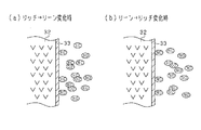
実空燃比がリッチとリーンとで変化する際のO2センサ17の検出応答性について説明する。エンジン10から排出される排気において実空燃比(第1触媒下流側の実空燃比)がリッチ/リーンで変化する際には排気の成分組成が変わる。このとき、その変化の直前における排気成分の残留により、変化後の空燃比に対するO2センサ17の出力変化(すなわちセンサ出力の応答性)が遅くなる。具体的には、リッチからリーンへの変化時には、図4(a)に示すように、リーン切替直後にリッチ成分であるHC等が排気側電極層33付近に残留し、このリッチ成分により、センサ電極でのリーン成分(NOx等)の反応が妨げられる。その結果、O2センサ17としてリーン出力の応答性が低下する。また、リーンからリッチへの変化時には、図4(b)に示すように、リッチ変化直後にリーン成分であるNOx等が排気側電極層33付近に残留し、このリーン成分により、センサ電極でのリッチ成分(HC等)の反応が妨げられる。その結果、O2センサ17としてリッチ出力の応答性が低下する。
The detection response of the
O2センサ17の出力変化を図5のタイムチャートで説明する。図5において、実空燃比がリッチ及びリーンで変化すると、その実空燃比の変化に応じてセンサ出力がリッチガス検出値(0.9V)とリーンガス検出値(0V)とで変化する。ただしこの場合、実空燃比の変化に対してセンサ出力は遅れを伴い変化する。図5では、リッチ→リーンの変化時には、実空燃比の変化に対してセンサ出力がTD1の遅れで変化し、リーン→リッチの変化時には、実空燃比の変化に対してセンサ出力がTD2の遅れで変化するようになっている。
The output change of the
そこで本実施形態では、空燃比のリーン変化時の検出応答性、及びリッチ変化時の検出応答性の少なくともいずれかについて、O2センサ17の検出応答性に関する変更要求の有無を判定するとともに、変更要求が有ると判定された場合に、その変更要求に基づいて定電流制御を実施して、O2センサ17の検出応答性を任意に調整する。センサ応答性の制御としては、一対のセンサ電極間に所定方向で電流を流し、それによりO2センサ17の検出応答性を可変に制御することとしている。具体的には、図2に示すように、大気側電極層34に定電流供給手段としての定電流回路27を接続し、その定電流回路27による定電流Icsの供給をマイコン26により制御することとしている。この場合、マイコン26は、一対のセンサ電極間に流れる定電流Icsの向きと量とを設定し、その設定した定電流Icsが流れるように定電流回路27を制御する。
Therefore, in the present embodiment, whether or not there is a change request regarding the detection response of the
詳しくは、定電流回路27は、大気側電極層34に対して、正逆両方向いずれかの向きで定電流Icsを供給するものであり、さらにその定電流量を可変に調整できるものである。つまり、マイコン26は、PWM制御により定電流Icsを可変に制御する。かかる場合、定電流回路27では、マイコン26から出力されるデューティ信号に応じて定電流Icsが調整され、その電流量調整された定電流Icsが排気側電極層33と大気側電極層34との電極間に流れることとなる。
Specifically, the constant
なお本実施形態では、排気側電極層33→大気側電極層34の向きに流れる定電流Icsを負の定電流(−Ics)、大気側電極層34→排気側電極層33の向きに流れる定電流Icsを正の定電流(+Ics)としている。
In this embodiment, the constant current Ics that flows in the direction of the exhaust
例えば、リッチからリーンへの変化時の検出応答性(リーン感度)を高める場合には、図6(a)に示すように、固体電解質層32内を通じて大気側電極層34から排気側電極層33に酸素が供給されるように定電流Ics(負の定電流Ics)が流される。この場合、大気側から排気側に酸素が供給されることにより、排気側電極層33の周囲に存在(残留)しているリッチ成分(HC)について酸化反応が促進され、それに伴いリッチ成分をいち早く除去できる。これにより、排気側電極層33においてリーン成分(NOx)が反応しやすくなり、結果としてO2センサ17のリーン出力の応答性が向上する。
For example, in order to increase the detection response (lean sensitivity) at the time of change from rich to lean, as shown in FIG. 6A, the atmosphere
また、リーンからリッチへの変化時の検出応答性(リッチ感度)を高める場合には、図6(b)に示すように、固体電解質層32内を通じて排気側電極層33から大気側電極層34に酸素が供給されるように定電流Ics(正の定電流Ics)が流される。この場合、排気側から大気側に酸素が供給されることにより、排気側電極層33の周囲に存在(残留)しているリーン成分(NOx)について還元反応が促進され、それに伴いリーン成分をいち早く除去できる。これにより、排気側電極層33においてリッチ成分(HC)が反応しやすくなり、結果としてO2センサ17のリッチ出力の応答性が向上する。
Further, in the case where the detection responsiveness (rich sensitivity) at the time of change from lean to rich is increased, as shown in FIG. 6B, the exhaust-
図7は、リーン変化時の検出応答性(リーン感度)を高める場合、及びリッチ変化時の検出応答性(リッチ感度)を高める場合におけるO2センサ17の出力特性(起電力特性)を示す図である。
FIG. 7 is a diagram showing output characteristics (electromotive force characteristics) of the
リーン変化時の検出応答性(リーン感度)を高める場合において、上記のとおり固体電解質層32内を通じて大気側電極層34から排気側電極層33に酸素が供給されるように負の定電流Icsが流されると(図6(a)参照)、図7の(a)に示すように、出力特性線がリッチ側にシフトする(より詳細には、リッチ側かつ起電力減少側にシフトする)。この場合、実際の空燃比がストイキ近傍のリッチ域にあってもセンサ出力がリーン出力となる。これは、O2センサ17の出力特性として、リーン変化時の検出応答性(リーン感度)が高められていることを意味する。
In the case of increasing the detection responsiveness (lean sensitivity) at the time of lean change, the negative constant current Ics is set so that oxygen is supplied from the atmosphere-
また、リッチ変化時の検出応答性(リッチ感度)を高める場合において、上記のとおり固体電解質層32内を通じて排気側電極層33から大気側電極層34に酸素が供給されるように正の定電流Icsが流されると(図6(b)参照)、図7の(b)に示すように、出力特性線がリーン側にシフトする(より詳細には、リーン側かつ起電力増加側にシフトする)。この場合、実際の空燃比がストイキ近傍のリーン域にあってもセンサ出力がリッチ出力となる。これは、O2センサ17の出力特性として、リッチ変化時の検出応答性(リッチ感度)が高められていることを意味する。
Further, in the case of increasing the detection responsiveness (rich sensitivity) at the time of rich change, a positive constant current is supplied so that oxygen is supplied from the exhaust
図8は、O2センサ17の検出応答性を可変に制御するためのセンサ応答性制御の処理手順を示すフローチャートである。本処理は、マイコン26により所定の時間周期で繰り返し実行される。
FIG. 8 is a flowchart showing a processing procedure of sensor response control for variably controlling the detection response of the
図8では、ステップS11〜S13において、O2センサ17の検出応答性を変更するための変更要求の有無を判定し、ステップS14〜S17において、実際にO2センサ17の検出応答性を変更すべく、変更要求の判定結果に基づいて定電流制御を実施する。
In FIG. 8, in steps S11 to S13, it is determined whether there is a change request for changing the detection response of the
詳しくは、ステップS11では、エンジン10が始動時等の冷間状態にあるか否かを判定する。この判定はエンジン運転状態に基づいて実施されればよく、具体的には、
・エンジン水温が所定温度以下であること、
・エンジン潤滑油の油温が所定温度以下であること、
・燃料経路内の燃料温度が所定温度以下であること、
のいずれかが成立する場合に、エンジン10が冷間状態にあると判定される。
Specifically, in step S11, it is determined whether or not the
・ The engine water temperature is below the specified temperature.
-The oil temperature of the engine lubricating oil is below the specified temperature,
-The fuel temperature in the fuel path is below the specified temperature,
If any of the above holds, it is determined that the
ステップS11がYESであると判定されることは、リッチ変化時の検出応答性を高める変更要求が有ると判定されることに相当する。この場合、ステップS14に進み、リッチ変化時の検出応答性を高める変更要求に基づいて定電流Icsの供給を制御する。具体的には、定電流回路27の定電流として「正の定電流Ics」を設定する。このとき、マイコン26により定電流回路27が制御され、排気側電極層33から大気側電極層34に酸素が供給される向きで定電流Ics(正の定電流Ics)が流れることとなる。これにより、エンジン10が冷間状態にある場合においてリッチ変化時の検出応答性が高められる。なお、定電流量はあらかじめ定められた所定値であるとよい。
Determining that Step S11 is YES corresponds to determining that there is a change request for improving detection responsiveness at the time of rich change. In this case, the process proceeds to step S14, and the supply of the constant current Ics is controlled based on the change request for improving the detection response at the time of rich change. Specifically, “positive constant current Ics” is set as the constant current of the constant
また、ステップS12では、エンジン10が高負荷運転状態になっているか否かを判定する。この判定はエンジン運転状態に基づいて実施されればよく、具体的には、
・気筒内への充填空気量が所定量以上であること、
・気筒内での燃焼圧が所定値以上であること、
・アクセル開度が所定値以上であること、
のいずれかが成立する場合に、エンジン10が高負荷運転状態になっていると判定される。
In step S12, it is determined whether or not the
-The amount of air charged into the cylinder is greater than or equal to a predetermined amount,
-The combustion pressure in the cylinder is above a predetermined value,
-The accelerator opening is greater than or equal to a predetermined value,
If any of the above holds, it is determined that the
ステップS12がYESであると判定されることは、リーン変化時の検出応答性を高める変更要求が有ると判定されることに相当する。この場合、ステップS15に進み、リーン変化時の検出応答性を高める変更要求に基づいて定電流Icsの供給を制御する。具体的には、定電流回路27の定電流として「負の定電流Ics」を設定する。このとき、マイコン26により定電流回路27が制御され、大気側電極層34から排気側電極層33に酸素が供給される向きで定電流Ics(負の定電流Ics)が流れることとなる。これにより、エンジン10が高負荷運転状態になっている場合においてリーン変化時の検出応答性が高められる。なお、定電流量はあらかじめ定められた所定値であるとよい。
Determining that Step S12 is YES corresponds to determining that there is a change request for improving the detection responsiveness at the time of lean change. In this case, the process proceeds to step S15, and the supply of the constant current Ics is controlled based on the change request for improving the detection response at the time of the lean change. Specifically, “negative constant current Ics” is set as the constant current of the constant
ここで、上記の高負荷運転時を想定すると、その高負荷運転期間には、エンジン負荷が増加側に変化する過渡時と、その負荷増加により高負荷となっている高負荷定常時とが含まれる。この場合、過渡時及び高負荷定常時にはいずれもリーン変化時の検出応答性が高められるが、その検出応答性を高めるにあたって、過渡時と高負荷定常時とで、検出応答性として要求される応答性レベルを相違させるようにするとよい。具体的には、過渡時の応答性レベルを高負荷定常時の応答性レベルよりも高応答とする。 Here, assuming the above-described high load operation, the high load operation period includes a transient time when the engine load changes to an increasing side and a high load steady time when the load increases due to the load increase. It is. In this case, the detection response at the time of lean change is enhanced both at the time of transient and at high load steady state, but in order to increase the detection response, the response required as detection response at transient and high load steady state Different gender levels are recommended. Specifically, the response level at the time of transition is set to be higher than the response level at the time of steady high load.
つまり、エンジン10が高負荷運転状態になっていると判定された場合(ステップS12がYESの場合)において、さらに「過渡時であること」、「高負荷定常時であること」をそれぞれ判定する。過渡時であると判定されることは、リーン変化時の検出応答性を高めつつも、その応答性レベルを比較的小さくする(高負荷定常時よりも小さくする)との変更要求が有ると判定されることに相当し、高負荷定常時であると判定されることは、リーン変化時の検出応答性を高めつつ、その応答性レベルを比較的大きくする(過渡時よりも大きくする)との変更要求が有ると判定されることに相当する。そして、過渡時である場合、高負荷定常時である場合のそれぞれにおいて、都度の変更要求に基づいて定電流Icsの供給を制御する。
That is, when it is determined that the
また、ステップS13では、現時点が燃料カットから燃料噴射への復帰直後であって、両触媒15a,15bの中立化のためのリッチ噴射制御が実施されているか否かを判定する。リッチ噴射制御は、エンジン10の燃料カットからの復帰時において、O2センサ17の検出結果に基づいて、両触媒15a,15bの酸素過多の状態(極リーンの雰囲気)を解消すべく空燃比を一時的にリッチ化する空燃比制御である。このリッチ噴射制御では、燃料噴射量のリッチ化により両触媒15a,15bの雰囲気が中立化される(ストイキ付近で保持される状態とされる)。そして、燃料カットからの復帰後においてO2センサ17の出力がリーン値からリッチ値に移行したタイミングで、そのリッチ噴射制御が終了される。本実施形態では、このリッチ噴射制御を実施する場合に、リッチ変化時の検出応答性を低めることとしている。
Further, in step S13, it is determined whether or not the current time is immediately after the return from the fuel cut to the fuel injection, and the rich injection control for neutralizing both the
ステップS13がYESであると判定されることは、リッチ変化時の検出応答性を低める変更要求が有ると判定されることに相当する。この場合、ステップS16に進み、リッチ変化時の検出応答性を低める変更要求に基づいて定電流Icsの供給を制御する。具体的には、定電流回路27の定電流として「負の定電流Ics」を設定する(リーン変化時の検出応答性を高める場合と同じ)。このとき、マイコン26により定電流回路27が制御され、大気側電極層34から排気側電極層33に酸素が供給される向きで定電流Ics(負の定電流Ics)が流れることとなる。これにより、リッチ噴射制御を実施する場合においてリッチ変化時の検出応答性が低められる。なお、定電流量はあらかじめ定められた所定値であるとよい。
The determination that step S13 is YES corresponds to the determination that there is a change request for reducing the detection responsiveness at the time of rich change. In this case, the process proceeds to step S16, and the supply of the constant current Ics is controlled based on the change request for reducing the detection response at the time of rich change. Specifically, “negative constant current Ics” is set as the constant current of the constant current circuit 27 (the same as the case where the detection response at the time of lean change is enhanced). At this time, the constant
また、ステップS11〜S13が全てNOとなる場合には、ステップS17に進み、O2センサ17の検出応答性を基準応答性に対して変更しない制御、すなわち定電流Ics=0とする制御を実施する。
Further, when all of Steps S11 to S13 are NO, the process proceeds to Step S17, and the control for changing the detection response of the
なお、図8のセンサ応答性制御処理では、ステップS11〜S13においてそれぞれ判定処理を実施する構成としたが、このうちいずれか1つ又は2つを実施する構成としてもよい。 In addition, in the sensor responsiveness control process of FIG. 8, although it was set as the structure which each performs a determination process in step S11-S13, it is good also as a structure which implements any one or two of them.
図9は、本実施形態におけるセンサ出力の挙動を説明するためのタイムチャートであり、(a)は、リーン変化時の検出応答性を高める場合について示し、(b)は、リッチ変化時の検出応答性を高める場合について示している。 FIG. 9 is a time chart for explaining the behavior of the sensor output in the present embodiment. FIG. 9A shows the case where the detection responsiveness at the time of lean change is increased, and FIG. 9B shows the detection at the time of rich change. It shows a case where responsiveness is improved.
図9において、実空燃比がリッチ及びリーンで交互に変化すると、その実空燃比の変化に応じてセンサ出力がリッチガス検出値(0.9V)とリーンガス検出値(0V)とで交互に変化する。このとき、(a)では、センサ電極間に負の定電流Icsが流れており、大気側電極層34から排気側電極層33に向けて酸素が供給されている(図6(a)の状態)。そのため、タイミングt1,t2で実空燃比がリッチからリーンに変化する際には、その変化直後においてリッチ成分の除去が促され、センサ出力がリーン側に変化する際の検出応答性が改善されている(リーン変化時の遅れ時間が図5のTD1よりも短縮されている)。
In FIG. 9, when the actual air-fuel ratio changes alternately between rich and lean, the sensor output alternately changes between the rich gas detection value (0.9 V) and the lean gas detection value (0 V) in accordance with the change in the actual air-fuel ratio. At this time, in (a), a negative constant current Ics flows between the sensor electrodes, and oxygen is supplied from the atmosphere-
ここで、センサ出力がリッチガス検出値からリーンガス検出値に変化する際には、センサ出力変化の遅延が抑制できることに加えて、その変化の傾きが従来技術(センサ電極間に電流供給しない構成)に比べて急峻なものとなる。これは、以下の理由による。つまり、センサ出力がリッチガス検出値からリーンガス検出値に変化する際には、図9(a)のタイミングt1直後のように既に実空燃比がリーンになっているとしても、リーンガス中には若干量のリッチ成分が含まれている。この場合、センサ出力のリッチ→リーン移行期間(図9のt1直後)で負の定電流Icsが流れていることで、センサ出力がリッチガス検出値からリーンガス検出値にいち早く移行することとなり、従来技術よりもセンサ出力の変化の傾きが大きくなる。 Here, when the sensor output changes from the rich gas detection value to the lean gas detection value, in addition to suppressing the delay of the sensor output change, the slope of the change is the conventional technology (configuration in which no current is supplied between the sensor electrodes). It is steep compared to this. This is due to the following reason. That is, when the sensor output changes from the rich gas detection value to the lean gas detection value, even if the actual air-fuel ratio is already lean as in the case immediately after timing t1 in FIG. Contains rich ingredients. In this case, since the negative constant current Ics flows during the rich-to-lean transition period of the sensor output (immediately after t1 in FIG. 9), the sensor output quickly shifts from the rich gas detection value to the lean gas detection value. The slope of the change in sensor output becomes larger than that.
また、(b)では、センサ電極間に正の定電流Icsが流れており、排気側電極層33から大気側電極層34に向けて酸素が供給されている(図6(b)の状態)。そのため、タイミングt3,t4で実空燃比がリーンからリッチに変化する際には、その変化直後においてリーン成分の除去が促され、センサ出力がリッチ側に変化する際の検出応答性が改善されている(リッチ変化時の遅れ時間が図5のTD2よりも短縮されている)。
In FIG. 6B, a positive constant current Ics flows between the sensor electrodes, and oxygen is supplied from the exhaust-
なお、センサ出力がリーン→リッチで変化する際にも、リッチ→リーンの変化時と同様に、センサ出力変化の遅延が抑制できることに加えて、その変化の傾きが従来技術(センサ電極間の電流供給しない構成)に比べて急峻なものとなっている。 When the sensor output changes from lean to rich, the delay of the sensor output change can be suppressed as well as the change from rich to lean, and the slope of the change is the conventional technology (current between the sensor electrodes). Compared to the configuration that does not supply).
以上詳述した本実施形態によれば、以下の優れた効果が得られる。 According to the embodiment described in detail above, the following excellent effects can be obtained.
リーン変化時の検出応答性、及びリッチ変化時の検出応答性のいずれかについて、O2センサ17の検出応答性を変更するための変更要求の有無を判定し、その変更要求に基づいて、一対のセンサ電極間に流れる定電流を制御する構成とした。これにより、空燃比のリーン/リッチ変化時においてO2センサ17の検出応答性を意図的に高めたり低めたりすることができる。換言すれば、本来検出したい所定ガス成分とは異なる成分(濃度検出に邪魔になる成分)についてその除去を早めたり、それとは逆に遅くしたりすることができる。また本実施形態では、定電流回路27によりO2センサ17に定電流Icsを供給してセンサ応答性を調整する構成としており、O2センサ17自体の設計変更等が強いられるものではなく、構成の煩雑化を抑制できる。以上により、簡易な構成を用いつつも、O2センサ17の検出応答性を好適に調整することができるものとなる。
With respect to either the detection responsiveness at the time of lean change or the detection responsiveness at the time of rich change, it is determined whether or not there is a change request for changing the detection response of the
また、リーン変化時の検出応答性とリッチ変化時の検出応答性とを択一的に高くする(又は低くする)場合に、いずれの検出応答性を高くすべきか(又は低くすべきか)は、エンジン10の運転状態によって都度相違すると考えられる。この点、エンジン運転状態に基づいて、各種の変更要求の有無を判定する構成としたため、時々のエンジン運転状態に対応させつつ、O2センサ17に対して都度適した検出応答性を付与することができる。
Further, when the detection response at the time of lean change and the detection response at the time of rich change are alternatively increased (or decreased), which detection response should be increased (or decreased) It is considered that it varies depending on the operating state of the
エンジン10が高負荷運転になっていると判断された場合に、リーン変化時の検出応答性を高める変更要求が有ると判定し、その変更要求に基づいて定電流を制御する構成とした。これにより、NOxの排出が増えることが懸念される高負荷運転状態において、リーン変化に対して高応答となる空燃比フィードバック制御を実施でき、NOxの排出を抑制できる。
When it is determined that the
また、エンジン10が冷間状態になっていると判断された場合に、リッチ変化時の検出応答性を高める変更要求が有ると判定し、その変更要求に基づいて定電流を制御する構成とした。これにより、HC等の排出が増えることが懸念されるエンジン冷間状態において、リッチ変化に対して高応答となる空燃比フィードバック制御を実施でき、HC等の排出を抑制できる。
Further, when it is determined that the
また、燃料カットからの復帰時にリッチ噴射制御が実施される場合に、リッチ変化時の検出応答性を低める変更要求が有ると判定し、その変更要求に基づいて定電流を制御する構成とした。これにより、リッチ噴射制御の実施中において実際の空燃比変化(リーン→リッチの変化)に対してO2センサ17の出力応答が遅れることになり、第1触媒15a(上流側触媒)が中立状態となった後、それから幾分遅れてリッチ噴射制御が終了されることになる。したがって、燃料カット後において、上流側及び下流側の両触媒15a,15bについて適正なる中立化の制御を実施でき、ひいては燃料カット直後における排気浄化を好適に実施できる。
Further, when the rich injection control is performed at the time of return from the fuel cut, it is determined that there is a change request for reducing the detection responsiveness at the time of the rich change, and the constant current is controlled based on the change request. As a result, the output response of the
定電流量を可変に調整できる構成とし、都度の変更要求に応じて検出応答性の応答性レベルを可変に制御する構成とした。これにより、リーン変化時の検出応答性とリッチ変化時の検出応答性とのバランスを考慮しつつ、検出応答性を可変に制御できる。 The configuration is such that the constant current amount can be variably adjusted, and the responsiveness level of the detection responsiveness is variably controlled according to each change request. Thereby, the detection response can be variably controlled while considering the balance between the detection response at the time of lean change and the detection response at the time of rich change.
エンジン10の高負荷運転時において、それが過渡時か高負荷定常時かを判定し、過渡時である場合に、その過渡時の応答性レベルを、高負荷定常時の応答性レベルよりも高応答とする構成とした。つまり、過渡時と高負荷定常時とを比べると、過渡時の方が、NOx等の排出量が意図せず増える懸念が大きいことを考慮して、過渡時の応答性レベルを、高負荷定常時の応答性レベルよりも高応答とした。これにより、リーン変化時の検出応答性とリッチ変化時の検出応答性とのバランスを保ちつつ、NOx等のリーン成分の排出を好適に抑制できる。
When the
(第2の実施形態)
次に、本発明の第2の実施形態について、上述した第1の実施形態との相違点を中心に説明する。本実施形態では、空燃比のリッチ/リーンの切り替わりが生じる際に、該切り替わり前後の空燃比に基づいて一対のセンサ電極間に所定方向で電流を流し、それによりO2センサ17の検出応答性を高めることとしている。本実施形態の構成では、空燃比がリッチ/リーンで変化するのに合わせて、定電流の向きを正負で切り替えることとしており、これは実空燃比の変動周期が比較的長い場合に特に有効なものとなっている。
(Second Embodiment)
Next, the second embodiment of the present invention will be described focusing on the differences from the first embodiment described above. In the present embodiment, when rich / lean switching of the air-fuel ratio occurs, a current flows in a predetermined direction between the pair of sensor electrodes based on the air-fuel ratio before and after the switching, thereby improving the detection response of the
図10は、O2センサ17の検出応答性を高めるために実施されるセンサ制御処理を示すフローチャートである。本処理は、マイコン26により所定の時間周期で繰り返し実行される。
FIG. 10 is a flowchart showing a sensor control process performed to improve the detection response of the
図10において、ステップS21では、O2センサ17の出力(起電力信号)を取り込む。また、ステップS22では、前回のセンサ出力と今回のセンサ出力との比較により、センサ出力がリッチからリーン側に変化するリーン向け変化時であるか否かを判定し、続くステップS23では、センサ出力が所定のリーン判定値THLに到達したか否かを判定する。なお、リーン判定値THLは、センサ出力がリーンガス検出値(0V)に到達したことを判定するしきい値であり、そのリーンガス検出値付近の値(例えば0.1V)である。
In FIG. 10, in step S21, the output (electromotive force signal) of the
ステップS22,S23が共にYESの場合、ステップS24に進み、定電流回路27の定電流として「正の定電流Ics」を設定する。この場合、マイコン26により定電流回路27が制御され、排気側電極層33から大気側電極層34に酸素が供給される向きで定電流Ics(正の定電流Ics)が流れることとなる。
When both steps S22 and S23 are YES, the process proceeds to step S24, where “positive constant current Ics” is set as the constant current of the constant
その後、ステップS25では、前回のセンサ出力と今回のセンサ出力との比較により、センサ出力がリーンからリッチ側に変化するリッチ向け変化時であるか否かを判定し、続くステップS26では、センサ出力が所定のリッチ判定値THRに到達したか否かを判定する。なお、リッチ判定値THRは、センサ出力がリッチガス検出値(0.9V)に到達したことを判定するしきい値であり、そのリッチガス検出値(例えば0.8V)である。 After that, in step S25, it is determined whether or not the sensor output is a rich change that changes from lean to rich by comparing the previous sensor output with the current sensor output. In subsequent step S26, the sensor output is determined. It is determined whether or not has reached a predetermined rich determination value THR. The rich determination value THR is a threshold value for determining that the sensor output has reached the rich gas detection value (0.9 V), and is the rich gas detection value (for example, 0.8 V).
ステップS25,S26が共にYESの場合、ステップS27に進み、定電流回路27の定電流として「負の定電流Ics」を設定する。この場合、マイコン26により定電流回路27が制御され、大気側電極層34から排気側電極層33に酸素が供給される向きで定電流Ics(負の定電流Ics)が流れることとなる。
If both steps S25 and S26 are YES, the process proceeds to step S27, where “negative constant current Ics” is set as the constant current of the constant
図11は、本実施形態におけるセンサ出力の挙動を説明するためのタイムチャートである。図11において、実空燃比がリッチ及びリーンで変化すると、その実空燃比の変化に応じてセンサ出力がリッチガス検出値(0.9V)とリーンガス検出値(0V)とで変化する。またこのとき、センサ出力がリッチガス検出値(0.9V)に収束してから、その後リーンガス検出値(0V)に到達するまでの期間(t10〜t12の期間)では、センサ電極間に負の定電流Icsが流されているとともに、センサ出力がリーンガス検出値(0V)に収束してから、その後リッチガス検出値(0.9V)に到達するまでの期間(t12〜t14の期間)では、センサ電極間に正の定電流Icsが流されている。 FIG. 11 is a time chart for explaining the behavior of the sensor output in the present embodiment. In FIG. 11, when the actual air-fuel ratio changes between rich and lean, the sensor output changes between the rich gas detection value (0.9 V) and the lean gas detection value (0 V) in accordance with the change in the actual air-fuel ratio. Further, at this time, in a period from the time when the sensor output converges to the rich gas detection value (0.9 V) to the time when the sensor output reaches the lean gas detection value (0 V) (a period from t10 to t12), a negative constant is detected between the sensor electrodes. During the period (t12 to t14) from when the current Ics is applied and the sensor output converges to the lean gas detection value (0 V) until the rich gas detection value (0.9 V) is reached, the sensor electrode A positive constant current Ics flows between them.
ここで、実空燃比のリッチからリーンへの切り替わりタイミング(例えばタイミングt11)では、センサ電極間に負の定電流Icsが流れており、大気側電極層34から排気側電極層33に向けて酸素が供給されている(図6(a)の状態)。そのため、実空燃比のリーン切り替わり直後においてリッチ成分の除去が促され、センサ出力がリーン側に変化する際の検出応答性が改善されている。その後、タイミングt12では、センサ出力がリーン判定値THLに到達することにより、定電流Icsが「負の定電流Ics」から「正の定電流Ics」に切り替えられる。
Here, at the switching timing of the actual air-fuel ratio from rich to lean (for example, timing t11), a negative constant current Ics flows between the sensor electrodes, and oxygen flows from the atmosphere-
また、実空燃比のリーンからリッチへの切り替わりタイミング(例えばタイミングt13)では、センサ電極間に正の定電流Icsが流れており、排気側電極層33から大気側電極層34に向けて酸素が供給されている(図6(b)の状態)。そのため、実空燃比のリッチ切り替わり直後においてリーン成分の除去が促され、センサ出力がリッチ側に変化する際の検出応答性が改善されている。その後、タイミングt14では、センサ出力がリッチ判定値THRに到達することにより、定電流Icsが「正の定電流Ics」から「負の定電流Ics」に切り替えられる。
Further, at the switching timing of the actual air-fuel ratio from lean to rich (for example, timing t13), a positive constant current Ics flows between the sensor electrodes, and oxygen flows from the exhaust
図11においては、空燃比がリッチからリーンに変化する場合には、センサ出力(起電力電圧)のリーン側への変化が収束した時点(タイミングt12)で、正の定電流Icsが流れる向きで(すなわち、センサ電極間に排気のリーン成分除去となる向きで)電流供給が開始される。また、空燃比がリーンからリッチに変化する場合には、センサ出力(起電力電圧)のリッチ側への変化が収束した時点(タイミングt14)で、負の定電流Icsが流れる向きで(すなわち、センサ電極間に排気のリーン成分除去となる向きで)電流供給が開始される。 In FIG. 11, when the air-fuel ratio changes from rich to lean, the positive constant current Ics flows in the direction in which the change of the sensor output (electromotive force voltage) to the lean side converges (timing t12). The current supply is started (that is, in a direction to remove the lean component of the exhaust gas between the sensor electrodes). Further, when the air-fuel ratio changes from lean to rich, the negative constant current Ics flows in the direction in which the change to the rich side of the sensor output (electromotive force voltage) converges (timing t14) (that is, in other words, Current supply is started between the sensor electrodes (in a direction that removes the lean component of the exhaust).
センサ出力がリッチガス検出値からリーンガス検出値に変化する際には、センサ出力変化の遅延が抑制できることに加えて、その変化の傾きが従来技術(センサ電極間に電流供給しない構成)に比べて急峻なものとなる。これは、以下の理由による。つまり、センサ出力がリッチガス検出値からリーンガス検出値に変化する際には、図11のタイミングt11〜t12のように既に実空燃比がリーンになっているとしても、リーンガス中には若干量のリッチ成分が含まれている。この場合、センサ出力のリッチ→リーン移行期間(図11のt11〜t12の期間)で負の定電流Icsを流すことで、センサ出力がリッチガス検出値からリーンガス検出値にいち早く移行することとなり、従来技術よりもセンサ出力の変化の傾きが大きくなる。 When the sensor output changes from the rich gas detection value to the lean gas detection value, in addition to being able to suppress the delay in the sensor output change, the slope of the change is steeper than in the prior art (a configuration in which no current is supplied between the sensor electrodes). It will be something. This is due to the following reason. That is, when the sensor output changes from the rich gas detection value to the lean gas detection value, even if the actual air-fuel ratio is already lean as shown at timings t11 to t12 in FIG. 11, a slight amount of rich gas is present in the lean gas. Contains ingredients. In this case, by flowing a negative constant current Ics during the sensor output rich-to-lean transition period (period t11 to t12 in FIG. 11), the sensor output quickly shifts from the rich gas detection value to the lean gas detection value. The slope of the change in sensor output is greater than that of technology.
なお、センサ出力がリーン→リッチで変化する際にも同様に、センサ出力変化の遅延が抑制できることに加えて、その変化の傾きが従来技術(センサ電極間の電流供給しない構成)に比べて急峻なものとなる。 Similarly, when the sensor output changes from lean to rich, the delay of the change in the sensor output can be similarly suppressed, and the inclination of the change is steeper than that in the conventional technique (configuration in which no current is supplied between the sensor electrodes). It will be something.
ここで、発明者は、センサ出力の応答性改善の効果を実験により確認した。その実験結果を図12を用いて説明する。評価条件としては、図12(a)に示すように、排気管内にリッチガス(CH4)を注入し続けた状態で、一時的にリーンガス(NO)を注入することにより実車両環境を模擬した。そして、上記の評価条件の下、所定の電圧値(例えば0.5V)を出力変化の判定しきい値としてリーンガス応答時間、リッチガス応答時間を計測した。 Here, the inventor confirmed the effect of improving the response of the sensor output by experiments. The experimental results will be described with reference to FIG. As an evaluation condition, as shown in FIG. 12A, an actual vehicle environment was simulated by injecting lean gas (NO) temporarily while injecting rich gas (CH4) into the exhaust pipe. Then, under the above evaluation conditions, the lean gas response time and the rich gas response time were measured using a predetermined voltage value (for example, 0.5 V) as an output change determination threshold value.
図12(b)、(c)は、リーンガス応答時間、リッチガス応答時間の計測結果を示す図である。これは、リッチ→リーン変化時には負の定電流Icsを流した状態/流していない状態でそれぞれ時間計測し、リーン→リッチ変化時には正の定電流Icsを流した状態/流していない状態でそれぞれ時間計測したものである。図12(b)、(c)においては、空燃比変化に際して所定方向に定電流Icsを流すことにより、センサ出力の応答性が改善されていることを確認できる。 12B and 12C are diagrams showing the measurement results of the lean gas response time and the rich gas response time. This is a time measurement in a state where a negative constant current Ics is supplied / not supplied at the time of rich → lean change, and a time is measured in a state where a positive constant current Ics is supplied / not supplied at the time of lean → rich change. It is measured. 12B and 12C, it can be confirmed that the responsiveness of the sensor output is improved by flowing the constant current Ics in a predetermined direction when the air-fuel ratio is changed.
また、空燃比のリッチ/リーンの切り替わりに際し、吸入空気量やエンジン回転速度等のエンジン運転状態に基づいて、定電流回路27の定電流Icsを可変に制御することが可能である。
Further, when the air-fuel ratio is switched between rich and lean, the constant current Ics of the constant
例えば、エンジンの吸入空気量が多い状態では、空燃比の切り替わり時においてセンサ出力の応答性を妨げる程度が大きくなる。そこで、図13(a)に示すように、エンジンの吸入空気量が多いほど、定電流Icsを大きい値とする。また、エンジン回転速度が高い状態では、空燃比の切り替わり時においてセンサ出力の応答性を妨げる程度が大きくなる。そこで、図13(b)に示すように、エンジン回転速度が高いほど、定電流Icsを大きい値とする。吸入空気量に代えて、排気流量の検出値又は推定値を用いることも可能である。 For example, in a state where the intake air amount of the engine is large, the degree to which the response of the sensor output is hindered when the air-fuel ratio is switched increases. Therefore, as shown in FIG. 13A, the constant current Ics is set to a larger value as the intake air amount of the engine is larger. Further, in a state where the engine speed is high, the degree to which the response of the sensor output is hindered when the air-fuel ratio is switched increases. Therefore, as shown in FIG. 13B, the constant current Ics is set to a larger value as the engine speed is higher. Instead of the intake air amount, a detected value or an estimated value of the exhaust flow rate can be used.
図13(a),(b)の関係を用いて定電流Icsを設定することにより、エンジン運転状態が変わっても、O2センサ17の検出応答性を都度適切に設定できる。
By setting the constant current Ics using the relationship shown in FIGS. 13A and 13B, the detection response of the
以上詳述した本実施形態によれば、以下の優れた効果が得られる。 According to the embodiment described in detail above, the following excellent effects can be obtained.
空燃比のリッチ/リーンの切り替わりが生じる際に、該切り替わり前後の空燃比に基づいて、すなわち空燃比の変化がリッチ→リーンか、リーン→リッチかに基づいて、センサ電極33,34間に所定方向で定電流Icsを供給する構成としたため、空燃比の切り替わり時において切り替わり先の空燃比の検出を早めることができる。また本実施形態では、定電流回路27を用いてO2センサ17に対する定電流Icsの供給を行う構成としており、O2センサ17自体の設計変更等が強いられるものではなく、構成の煩雑化を抑制できる。以上により、簡易な構成を用いつつも、O2センサ17の検出応答性の向上を図ることができる。
When the air-fuel ratio rich / lean switching occurs, a predetermined value is applied between the
センサ出力のリーン側への変化が収束した時点、又はセンサ出力のリッチ側への変化が収束した時点で、センサ電極33,34間に供給される定電流Icsの向きを反転させるようにした。これにより、リッチ→リーンの切り替わり時とリーン→リッチの切り替わり時とでは流すべき電流方向が逆になることを考慮しつつ、好適なる定電流の供給を実施できる。
The direction of the constant current Ics supplied between the
空燃比の切り替わりに際し、エンジン運転状態に基づいて、定電流Ics供給を制御する構成とした。これにより、エンジン運転状態が変わっても、O2センサ17の検出応答性を都度適切に設定できる。
When the air-fuel ratio is switched, the constant current Ics supply is controlled based on the engine operating state. Thereby, even if the engine operating state changes, the detection response of the
(他の実施形態)
本発明は上記実施形態の記載内容に限定されず、例えば次のように実施されてもよい。
(Other embodiments)
The present invention is not limited to the description of the above embodiment, and may be implemented as follows, for example.
・上記第1の実施形態において、O2センサ17の劣化状態を検出し、その検出結果により、O2センサ17の検出応答性に関する変更要求の有無を判定する構成としてもよい。具体的には、例えば燃料カットの開始時におけるセンサ出力の減少率(減少の傾き)を求め、その減少率の大きさに基づいてO2センサ17の劣化状態を検出する。このとき、減少率が小さいほど(減少の傾きが小さいほど)、劣化が進行していると推測できる。そして、燃料カットの開始時における減少率が所定値以下である場合に、O2センサ17の検出応答性に関する変更要求が有るとして、検出応答性を変更するための定電流制御を実施する。ただしこのとき、リーン側及びリッチ側のいずれの検出応答性を高めるかは、都度のエンジン運転状態等に応じて決定するとよい。また、劣化の程度に応じて定電流を可変に制御する構成であってもよい。その際には、例えば劣化の程度が大きいほど、定電流を大きくするとよい。
In the first embodiment, the deterioration state of the
・上記第2の実施形態において、エンジンの燃料カットからの復帰時に実空燃比がリーンからリッチに切り替わる場合には、燃料カット復帰時以外で実空燃比がリーンからリッチに切り替わる場合に比べて、定電流Icsを大きくするとよい。例えば、車両減速に伴い燃料カットが実行されている状態で車両加速が行われる場合、その車両加速の開始時点では、それ以前の燃料カットのために排気管14内に大気が充満している。この場合、燃料カットからの復帰直後(加速開始時点)にはセンサ周りに多量の酸素が残留することになるため、その状態を早期に解消すべく、正の定電流Ics(排気側電極層33→大気側電極層34に酸素供給するための供給電流量)を、燃料カット復帰時以外での場合に比べて多くする。これにより、燃料カットからの復帰時においてO2センサ17の検出応答性を高めることができる。
-In the second embodiment, when the actual air-fuel ratio switches from lean to rich when the engine returns from the fuel cut, compared to when the actual air-fuel ratio switches from lean to rich except when the fuel cut returns, The constant current Ics may be increased. For example, when vehicle acceleration is performed in a state where fuel cut is being performed as the vehicle is decelerated, the
・上記第2の実施形態において、車両加速時等に触媒等の排気系部品を保護するために高負荷増量が実施される場合に、その高負荷増量の終了時に実空燃比がリッチからリーンに切り替わる際には、高負荷増量の終了時以外で実空燃比がリッチからリーンに切り替わる際に比べて、定電流Icsを大きくするとよい。車両加速時等においてエンジンの高負荷増量が実施される場合には、排気管14内にリッチ成分が充満している。この場合、高負荷増量の終了直後にはセンサ周りにリッチ成分が残留することになるため、その状態を早期に解消すべく、負の定電流Ics(大気側電極層34→排気側電極層33に酸素供給するための供給電流量)を、高負荷増量の終了時以外での場合に比べて多くする。これにより、高負荷増量からの復帰時においてO2センサ17の検出応答性を高めることができる。
In the second embodiment, when high load increase is performed to protect exhaust system parts such as a catalyst during vehicle acceleration, the actual air-fuel ratio is changed from rich to lean at the end of the high load increase. At the time of switching, the constant current Ics is preferably made larger than when the actual air-fuel ratio is switched from rich to lean except at the end of the high load increase. When the engine is subjected to a high load increase during vehicle acceleration or the like, the
・上記第2の実施形態において、実空燃比がリッチ及びリーンで切り替わる際における定電流Icsの供給態様は、上述の図11のものに限定されない。例えば、図14に示すように、実空燃比のリッチ⇔リーン変化が生じる期間(過渡期間)でのみ定電流Icsを流す構成としてもよい。図14では、センサ出力がリッチガス検出値(0.9V)からリーン側に変化する期間(図のt21〜t22)で負の定電流Icsを流すとともに、センサ出力がリーンガス検出値(0V)からリッチ側に変化する期間(図のt23〜t24)で正の定電流Icsを流すようにし、それ以外では定電流Ics=0としている。かかる構成であっても、上記同様、簡易な構成を用いつつも、O2センサ17の検出応答性の向上を図ることができる。
In the second embodiment, the supply mode of the constant current Ics when the actual air-fuel ratio is switched between rich and lean is not limited to that shown in FIG. For example, as shown in FIG. 14, the constant current Ics may be supplied only during a period (transition period) in which a rich / lean change of the actual air-fuel ratio occurs. In FIG. 14, the negative constant current Ics is supplied during the period (t21 to t22 in the figure) in which the sensor output changes from the rich gas detection value (0.9V) to the lean side, and the sensor output is rich from the lean gas detection value (0V). The positive constant current Ics is allowed to flow during a period (t23 to t24 in the figure) that changes to the side, and the constant current Ics = 0 otherwise. Even with such a configuration, the detection response of the
また、図15に示すように定電流Icsを流す構成であってもよい。図15には、定電流Icsとして、3つの形態の定電流Ics1,Ics2,Ics3が示されている。なお、実空燃比の変化とセンサ出力の変化は上述の図11と同様であり、図示の内容を流用するとともに説明を割愛する。 Moreover, as shown in FIG. 15, the structure which sends the constant current Ics may be sufficient. FIG. 15 shows three forms of constant currents Ics1, Ics2, and Ics3 as the constant current Ics. Note that the change in the actual air-fuel ratio and the change in the sensor output are the same as in FIG. 11 described above, and the contents shown in the figure are diverted and description thereof is omitted.
図15において、定電流Ics1は、センサ出力がリッチガス検出値(0.9V)に収束してから、その後リーン側に変化してリーンガス検出値(0V)に到達するまでの期間(t10〜t12の期間)において負の定電流とされ、それ以外の期間ではIcs1=0となっている。この場合、リッチからリーンへの変化時のみを対象にセンサ応答性を向上させることができる。 In FIG. 15, the constant current Ics1 is a period (from t10 to t12) until the sensor output converges to the rich gas detection value (0.9V) and then changes to the lean side to reach the lean gas detection value (0V). (Period) is a negative constant current, and Ics1 = 0 in other periods. In this case, the sensor responsiveness can be improved only when changing from rich to lean.
また、定電流Ics2は、センサ出力がリーンガス検出値(0V)に収束してから、その後リッチ側に変化してリッチガス検出値(0.9V)に到達するまでの期間(t12〜t14の期間)において正の定電流とされ、それ以外の期間ではIcs2=0となっている。この場合、リーンからリッチへの変化時のみを対象にセンサ応答性を向上させることができる。 The constant current Ics2 is a period (t12 to t14) from when the sensor output converges to the lean gas detection value (0V) until it changes to the rich side and reaches the rich gas detection value (0.9V). The positive constant current is set at Ics2, and Ics2 = 0 in other periods. In this case, the sensor responsiveness can be improved only for the change from lean to rich.
さらに、定電流Ics3は、センサ出力のリッチ⇔リーンの切り替わりに合わせて負の定電流と正の定電流とで切り替えられることは上述の図11と同様であるが、負の定電流を流す場合の電流量ΔI1と、正の定電流を流す場合の電流量ΔI2とが異なるものとなっている。この場合、負の定電流を流すことで大気側(電極層34側)から排気側(電極層33側)に供給される酸素の量と、正の定電流を流すことで排気側(電極層33側)から大気側(電極層34側)に供給される酸素の量とを相違させ、それら前者後者のうち一方を他方よりも多くすることができる。
Further, the constant current Ics3 is switched between a negative constant current and a positive constant current in accordance with the switching of the rich / lean sensor output, as in FIG. Current amount ΔI1 and current amount ΔI2 when a positive constant current is passed are different. In this case, the amount of oxygen supplied from the atmosphere side (
特に図15では、ΔI1>ΔI2としている。これにより、正の定電流を流すことで排気側から大気側に供給される酸素の量を、負の定電流を流すことで大気側から排気側に供給される酸素の量よりも少なくすることができる。つまり、排気側から大気側に供給される酸素の量が制限されるようになっている。この場合、実空燃比がリーンである状態において、排気側から酸素を引きすぎてしまうことを抑制できる。ただし、図15とは逆に、ΔI1>ΔI2として定電流の制御を実施することも可能である。 In particular, in FIG. 15, ΔI1> ΔI2. As a result, the amount of oxygen supplied from the exhaust side to the atmosphere side by flowing a positive constant current is made smaller than the amount of oxygen supplied from the atmosphere side to the exhaust side by flowing a negative constant current. Can do. That is, the amount of oxygen supplied from the exhaust side to the atmosphere side is limited. In this case, in a state where the actual air-fuel ratio is lean, it can be suppressed that oxygen is excessively drawn from the exhaust side. However, contrary to FIG. 15, it is also possible to carry out constant current control with ΔI1> ΔI2.
・上記各実施形態では、O2センサ17の大気側電極層34に定電流回路27(電流供給手段)を接続する構成としたが、これを変更し、O2センサ17の排気側電極層33に定電流回路27を接続する構成としてもよい。また、両電極層33,34にそれぞれ定電流回路27を接続して設けることも可能である。
In each of the above embodiments, the constant current circuit 27 (current supply means) is connected to the atmosphere
・O2センサとして、積層型構造のO2センサを用いることも可能である。図16は、積層型O2センサのセンサ素子40の断面構成を示す。実際にはセンサ素子40は図16の紙面直交方向に延びる長尺状をなし、素子全体がハウジングや素子カバー内に収容される構成となっている。
-As the O2 sensor, an O2 sensor having a laminated structure can be used. FIG. 16 shows a cross-sectional configuration of the
センサ素子40は、長方形板状の部分安定化ジルコニア製のシートからなる固体電解質層41と、アルミナ等の高熱伝導性セラミックスからなる絶縁層42とを有し、これらが図の上下に積層されて構成されている。同素子の周囲には図示しない保護層が設けられている。固体電解質層41を挟んで上下一対の電極43,44が対向配置されている。絶縁層42には電極44に対面する部位に大気ダクト45が形成されている。また、同絶縁層42にはヒータ46が埋設されている。ヒータ46は、バッテリ電源からの通電により発熱する線状の発熱体よりなり、その発熱により素子全体を加熱する。
The
上記構成のセンサ素子40では、固体電解質層41の外側(電極43側)が排気雰囲気、同内側(電極44側)が大気雰囲気となっており、これら双方の酸素濃度の差(酸素分圧の差)に応じて電極43,44間で起電力が発生する。つまり、センサ素子40では、空燃比がリッチかリーンかで異なる起電力が発生する。これにより、O2センサは、排ガスの酸素濃度(すなわち空燃比)に応じた起電力信号を出力する。
In the
そして、大気側電極である電極44に定電流供給手段としての定電流回路27が接続されており、その定電流回路27による定電流Icsの供給が図示しないマイコン26により制御される構成となっている。センサ制御については上述した制御が採用される。
A constant
・上記第1の実施形態では、エンジンの排気を検出対象とし、O2センサ17の検出応答性に関して変更要求の有無を判定する構成としたが、これ以外に、図1に示すA/Fセンサ16について本発明を適用することとし、A/Fセンサ16の検出応答性に関して変更要求の有無を判定する構成としてもよい。
In the first embodiment, the engine exhaust is targeted for detection, and the presence / absence of a change request is determined for the detection responsiveness of the
また、固体電解質体と該固体電解質体の表面に設けられたHC検出用の一対のセンサ電極とを有し、HC濃度を検出するHCセンサについて、そのHC濃度の変化に対するHCセンサの検出応答性を変更する変更要求の有無を判定し、更要求が有ると判定された場合に、その変更要求に基づいて、一対のセンサ電極間に流れる定電流を制御する構成としてもよい。ここで、HC検出の応答性を高める場合には、固体電解質内を通じて排気側電極層から大気側電極層に酸素が供給されるように定電流(正の定電流)を流すようにするとよい。 An HC sensor having a solid electrolyte body and a pair of sensor electrodes for detecting HC provided on the surface of the solid electrolyte body, and detecting the HC concentration, is the detection response of the HC sensor to the change in the HC concentration. It is also possible to determine whether or not there is a change request for changing, and when it is determined that there is a change request, the constant current flowing between the pair of sensor electrodes may be controlled based on the change request. Here, in order to enhance the responsiveness of HC detection, a constant current (positive constant current) may be supplied so that oxygen is supplied from the exhaust side electrode layer to the atmosphere side electrode layer through the solid electrolyte.
或いは、固体電解質体と該固体電解質体の表面に設けられたNOx検出用の一対のセンサ電極とを有し、NOx濃度を検出するNOxセンサについて、そのNOx濃度の変化に対するNOxセンサの検出応答性を変更する変更要求の有無を判定し、更要求が有ると判定された場合に、その変更要求に基づいて、一対のセンサ電極間に流れる定電流を制御する構成としてもよい。ここで、NOx検出の応答性を高める場合には、固体電解質内を通じて大気側電極層から排気側電極層に酸素が供給されるように定電流(負の定電流)を流すようにするとよい。 Alternatively, for a NOx sensor that has a solid electrolyte body and a pair of sensor electrodes for NOx detection provided on the surface of the solid electrolyte body and detects the NOx concentration, the detection response of the NOx sensor to changes in the NOx concentration It is also possible to determine whether or not there is a change request for changing, and when it is determined that there is a change request, the constant current flowing between the pair of sensor electrodes may be controlled based on the change request. Here, in order to improve the responsiveness of NOx detection, a constant current (negative constant current) may be supplied so that oxygen is supplied from the atmosphere-side electrode layer to the exhaust-side electrode layer through the solid electrolyte.
・上記第2の実施形態では、エンジンの排気を検出対象とし、その排気がリッチ/リーンで切り替わる際のO2センサの検出応答性を向上させるものとしたが、これ以外の形態での具体化も可能である。要は、センサ検出対象となる被検出ガスは、ガス成分(ガス組成)の切り替わりが生じるものであればよく、ガスセンサの検出信号に基づいて被検出ガスに含まれる所定ガス成分の濃度を検出するものであればよい。例えば、図1のシステム構成において、第1触媒上流側のA/Fセンサ16について本発明を適用してもよい。
In the second embodiment, the engine exhaust is targeted for detection, and the detection response of the O2 sensor when the exhaust is switched between rich and lean is improved. However, other embodiments may be implemented. Is possible. In short, the gas to be detected as a sensor detection target may be any gas that changes the gas component (gas composition), and the concentration of the predetermined gas component contained in the gas to be detected is detected based on the detection signal of the gas sensor. Anything is acceptable. For example, the present invention may be applied to the A /
また、固体電解質体と該固体電解質体の表面に設けられたHC検出用の一対のセンサ電極とを有し、HC濃度を検出するHCセンサについて、排気が、HCが存在する状態と存在しない状態(微量な状態含む)とで切り替わる際に、その状態切り替わり前のガス成分に基づいてHCセンサに対する定電流Icsの供給態様を制御する。或いは、固体電解質体と該固体電解質体の表面に設けられたNOx検出用の一対のセンサ電極とを有し、NOx濃度を検出するNOxセンサについて、排気が、NOxが存在する状態と存在しない状態(微量な状態含む)とで切り替わる際に、その状態切り替わり前のガス成分に基づいてNOxセンサに対する定電流Icsの供給態様を制御する。車両用エンジン以外に、焼却炉の排出ガスを検出対象とするガスセンサに適用することも可能である。 In addition, for an HC sensor having a solid electrolyte body and a pair of sensor electrodes for detecting HC provided on the surface of the solid electrolyte body and detecting the HC concentration, exhaust is in a state where HC is present and in a state where HC is not present When switching between (including a minute state), the supply mode of the constant current Ics to the HC sensor is controlled based on the gas component before the state switching. Alternatively, for a NOx sensor that has a solid electrolyte body and a pair of sensor electrodes for detecting NOx provided on the surface of the solid electrolyte body and detects NOx concentration, the exhaust is in a state in which NOx is present and in a state in which NOx is not present When switching between (including a minute state), the supply mode of the constant current Ics to the NOx sensor is controlled based on the gas component before the state switching. In addition to the vehicle engine, the present invention can be applied to a gas sensor that detects exhaust gas from an incinerator.
また、上記のとおり記載した技術内容によれば、ガスセンサ制御装置として、以下の各技術的思想を抽出できる。 Further, according to the technical contents described above, the following technical ideas can be extracted as the gas sensor control device.
手段1.
固体電解質体と該固体電解質体の表面に設けられた一対のセンサ電極とを有するガスセンサに適用され、センサ検出対象となる被検出ガスはガス成分の切り替わりが生じるものであり、前記ガスセンサの検出信号に基づいて前記被検出ガスに含まれる所定ガス成分の濃度を演算するガスセンサ制御装置であって、
前記一対のセンサ電極の少なくともいずれかに電気的に接続され、その接続されたセンサ電極に対して定電流を供給する定電流供給手段と、
前記ガス成分の切り替わりに際し、その成分切り替わり前に前記被検出ガスに含まれているガス成分に基づいて、前記一対のセンサ電極間に所定方向で定電流が流れるように前記定電流供給手段を制御する電流制御手段と、
を備えることを特徴とするガスセンサ制御装置。
Applied to a gas sensor having a solid electrolyte body and a pair of sensor electrodes provided on the surface of the solid electrolyte body, a gas to be detected is a gas to be detected, and a detection signal of the gas sensor A gas sensor control device for calculating a concentration of a predetermined gas component contained in the detected gas based on
Constant current supply means that is electrically connected to at least one of the pair of sensor electrodes and supplies a constant current to the connected sensor electrodes;
When the gas component is switched, the constant current supply means is controlled so that a constant current flows in a predetermined direction between the pair of sensor electrodes based on the gas component contained in the detected gas before the component switching. Current control means for
A gas sensor control device comprising:
被検出ガスにおいてガス成分(ガス組成)の切り替わりが生じる際において、新たなガス成分が導入されても成分切り替わり前のガス成分がセンサ周りに残っていると、新たなガス成分の検出に対するセンサ検出信号の出力変化(すなわちセンサ応答性)が遅くなる。 When a gas component (gas composition) is switched in the gas to be detected, if the gas component before the component switching remains around the sensor even if a new gas component is introduced, sensor detection for detection of the new gas component The signal output change (that is, sensor response) becomes slow.
この点、上記構成によれば、ガス成分の切り替わりが生じる際に、その成分切り替わり前に被検出ガスに含まれるガス成分に基づいて、一対のセンサ電極間に所定方向で定電流が供給されるため、成分切り替わり前のガス成分をいち早く除去することができる。したがって、ガス成分の切り替わり時において新たなガス成分の検出を早めることができる。また、本発明では、定電流供給手段を用いてガスセンサに対する定電流の供給を行う構成としており、ガスセンサ自体の設計変更等が強いられるものではなく、構成の煩雑化を抑制できる。以上により、簡易な構成を用いつつも、ガスセンサの検出応答性の向上を図ることができる。 In this regard, according to the above configuration, when the gas component is switched, a constant current is supplied in a predetermined direction between the pair of sensor electrodes based on the gas component contained in the gas to be detected before the component switching. Therefore, the gas component before the component switching can be quickly removed. Therefore, the detection of a new gas component can be accelerated when the gas component is switched. Moreover, in this invention, it is set as the structure which supplies a constant current with respect to a gas sensor using a constant current supply means, The design change etc. of gas sensor itself are not forced, and complication of a structure can be suppressed. As described above, it is possible to improve the detection response of the gas sensor while using a simple configuration.
手段2.
内燃機関の排気を前記被検出ガスとして空燃比を検出するガスセンサに適用され、
前記電流制御手段は、前記ガス成分の切り替わりとして空燃比のリッチ/リーンの切り替わりが生じる際に、該切り替わり前後の空燃比に基づいて、前記一対のセンサ電極間に所定方向で定電流が流れるように前記定電流供給手段を制御する手段1に記載のガスセンサ制御装置。
Mean 2.
Applied to a gas sensor for detecting an air-fuel ratio using the exhaust gas of an internal combustion engine as the detected gas,
The current control means is configured to cause a constant current to flow between the pair of sensor electrodes in a predetermined direction based on the air-fuel ratio before and after the switching when the air-fuel ratio is switched between rich and lean as the gas component is switched. The gas sensor control apparatus according to
内燃機関から排出される排気の場合、空燃比についてリッチとリーンとで切り替わりが生じる。この場合、空燃比がリッチからリーンに切り替わる際には、リーン切替直後にリッチ成分であるHC等がセンサ周りに残留し、このリッチ成分により、センサ電極でのリーン成分(NOx等)の反応が妨げられる。その結果、ガスセンサとしてリーン出力の応答性が低下する。また、空燃比がリーンからリッチに切り替わる際には、リッチ切替直後にリーン成分であるNOx等がセンサ周りに残留し、このリーン成分により、センサ電極でのリッチ成分(HC等)の反応が妨げられる。その結果、ガスセンサとしてリッチ出力の応答性が低下する。 In the case of exhaust discharged from an internal combustion engine, the air-fuel ratio is switched between rich and lean. In this case, when the air-fuel ratio is switched from rich to lean, HC or the like, which is a rich component, remains around the sensor immediately after the lean switching, and this rich component causes the reaction of the lean component (NOx or the like) at the sensor electrode. Be disturbed. As a result, the responsiveness of the lean output as a gas sensor is lowered. Also, when the air-fuel ratio is switched from lean to rich, the lean component NOx or the like remains around the sensor immediately after the rich switching, and this lean component prevents the reaction of the rich component (HC or the like) at the sensor electrode. It is done. As a result, the response of rich output as a gas sensor is reduced.
この点、手段2では、空燃比のリッチ/リーンの切り替わりが生じる際に、該切り替わり前後の空燃比に基づいて、すなわち空燃比の変化がリッチ→リーンか、リーン→リッチかに基づいて、一対のセンサ電極間に所定方向で定電流が供給されるため、それら空燃比の切り替わり時においてセンサ検出信号の応答性を向上させることができる。 In this respect, when the air-fuel ratio rich / lean switching occurs, the means 2 is based on the air-fuel ratio before and after the switching, that is, based on whether the change in the air-fuel ratio is rich → lean or lean → rich. Since a constant current is supplied between the sensor electrodes in a predetermined direction, the response of the sensor detection signal can be improved when the air-fuel ratio is switched.
手段3.
前記ガスセンサは、前記一対のセンサ電極として、排気に晒される排気側電極と、所定酸素濃度となる基準室内の基準ガスに晒される基準室側電極とを有し、
前記電流制御手段は、空燃比がリッチからリーンに切り替わる際には、前記固体電解質体を通じて基準室側電極から排気側電極に酸素が供給される向きに定電流が流れるように、空燃比がリーンからリッチに切り替わる際には、前記固体電解質体を通じて排気側電極から基準室側電極に酸素が供給される向きに定電流が流れるように、前記定電流供給手段を制御する手段2に記載のガスセンサ制御装置。
The gas sensor has, as the pair of sensor electrodes, an exhaust side electrode that is exposed to exhaust gas, and a reference chamber side electrode that is exposed to a reference gas in a reference chamber having a predetermined oxygen concentration,
When the air-fuel ratio is switched from rich to lean, the current control means has a lean air-fuel ratio so that a constant current flows in a direction in which oxygen is supplied from the reference chamber side electrode to the exhaust side electrode through the solid electrolyte. The gas sensor according to claim 2, which controls the constant current supply means so that a constant current flows in a direction in which oxygen is supplied from the exhaust side electrode to the reference chamber side electrode through the solid electrolyte body when switching from rich to rich. Control device.
上記のように、リッチ→リーンの切り替わり時に、固体電解質体を通じて基準室側電極から排気側電極に酸素が供給されるようにすることで、排気側電極の周囲に存在(残留)しているリッチ成分(HC等)をいち早く除去し、その結果リーン出力の応答性を向上させることができる。また、リーン→リッチの切り替わり時に、固体電解質体を通じて排気側電極から基準室側電極に酸素が供給されるようにすることで、排気側電極の周囲に存在(残留)しているリーン成分(NOx等)をいち早く除去し、その結果リッチ出力の応答性を向上させることができる。 As described above, at the time of switching from rich to lean, oxygen is supplied from the reference chamber side electrode to the exhaust side electrode through the solid electrolyte body, so that the rich that exists (residual) exists around the exhaust side electrode. Components (HC, etc.) can be removed quickly, and as a result, the response of lean output can be improved. Further, when the gas is switched from lean to rich, oxygen is supplied from the exhaust side electrode to the reference chamber side electrode through the solid electrolyte body, so that the lean component (NOx) existing (residual) around the exhaust side electrode is present. Etc.) can be removed quickly, and as a result, the response of rich output can be improved.
手段4.
前記内燃機関の運転状態を検出する運転状態検出手段を備え、
前記定電流供給手段は、前記センサ電極への定電流量の調整が可能であり、
前記電流制御手段は、前記ガス成分の切り替わりに際し、前記運転状態検出手段により検出した機関運転状態に基づいて、前記定電流供給手段による定電流量を制御する手段2又は3に記載のガスセンサ制御装置。
Comprising an operating state detecting means for detecting an operating state of the internal combustion engine;
The constant current supply means is capable of adjusting a constant current amount to the sensor electrode,
The gas sensor control device according to
内燃機関の運転状態が相違すると、ガス成分の切り替わり時においてセンサ出力の応答性を妨げる影響の度合いが変わると考えられる。例えば、内燃機関の吸入空気量が多い状態、又はエンジン回転速度が高い状態では、ガス成分の切り替わり時においてセンサ出力の応答性を妨げる程度が大きくなる。この場合、吸入空気量が多い状態又はエンジン回転速度が高い状態では、定電流供給手段による定電流量を多くするとよい。これにより、内燃機関の運転状態が変わっても、ガスセンサの検出応答性を都度適切に設定できる。 If the operating state of the internal combustion engine is different, it is considered that the degree of influence that hinders the responsiveness of the sensor output when the gas component is switched is changed. For example, in a state where the intake air amount of the internal combustion engine is large or a state where the engine rotational speed is high, the degree to which the responsiveness of the sensor output is hindered when the gas component is switched increases. In this case, in a state where the intake air amount is large or the engine speed is high, the constant current amount by the constant current supply means may be increased. Thereby, even if the driving | running state of an internal combustion engine changes, the detection responsiveness of a gas sensor can be set appropriately each time.
手段5.
前記内燃機関の運転中に燃料カットを実施する内燃機関制御システムに適用され、
前記定電流供給手段は、前記センサ電極への定電流量の調整が可能であり、
前記電流制御手段は、前記ガス成分の切り替わりに際し、その切り替わりが前記燃料カットからの復帰に伴うものであることに基づいて、前記定電流供給手段による定電流量を制御する手段2乃至4のいずれか一項に記載のガスセンサ制御装置。
Applied to an internal combustion engine control system for performing fuel cut during operation of the internal combustion engine;
The constant current supply means is capable of adjusting a constant current amount to the sensor electrode,
The current control means is any one of means 2 to 4 for controlling the constant current amount by the constant current supply means, based on the fact that the change is accompanied by the return from the fuel cut when the gas component is changed. The gas sensor control device according to
燃料カット時には、内燃機関の排気通路内に大気が充満し、被検出ガスである排気が酸素過多の状態となる。この場合、燃料カットからの復帰直後には、センサ周りに多量の酸素が残留することになるため、定電流供給手段による定電流量(排気側電極→基準室側電極に酸素供給するための電流量)を多くするとよい。これにより、燃料カットからの復帰時においてガスセンサの検出応答性を高めることができる。 When the fuel is cut, the exhaust passage of the internal combustion engine is filled with the atmosphere, and the exhaust gas, which is the detected gas, is in an excessive oxygen state. In this case, since a large amount of oxygen remains around the sensor immediately after returning from the fuel cut, a constant current amount by the constant current supply means (current for supplying oxygen from the exhaust side electrode to the reference chamber side electrode) (Amount) should be increased. Thereby, the detection responsiveness of a gas sensor can be improved at the time of return from a fuel cut.
手段6.
前記内燃機関の運転中に燃料噴射量の高負荷増量を実施する内燃機関制御システムに適用され、
前記定電流供給手段は、前記センサ電極への定電流量が可能であり、
前記電流制御手段は、前記ガス成分の切り替わりに際し、その切り替わりが前記高負荷増量の終了に伴うものであることに基づいて、前記定電流供給手段による定電流量を制御する手段2乃至5のいずれか一項に記載のガスセンサ制御装置。
Means 6.
Applied to an internal combustion engine control system for performing a high load increase of the fuel injection amount during operation of the internal combustion engine;
The constant current supply means is capable of a constant current amount to the sensor electrode,
Any of the means 2 to 5 for controlling the constant current amount by the constant current supply means based on the fact that the switching is accompanied by the end of the increase in the high load when the gas component is switched. The gas sensor control device according to
排気系部品の保護を図るべく内燃機関の高負荷増量が実施される場合には、内燃機関の排気通路内にリッチ成分が充満し、被検出ガスである排気がリッチ成分過多の状態となる。この場合、高負荷増量の終了直後には、センサ周りにリッチ成分が残留することになるため、そのリッチ残留分を排除することを目的として、定電流供給手段による定電流量(基準室側電極→排気側電極に酸素供給するための電流量)を多くするとよい。これにより、高負荷増量からの復帰時においてガスセンサの検出応答性を高めることができる。 When a high load increase of the internal combustion engine is performed in order to protect the exhaust system parts, the exhaust gas passage of the internal combustion engine is filled with a rich component, and the exhaust gas that is the detected gas becomes rich. In this case, since a rich component remains around the sensor immediately after the end of the high load increase, the constant current amount (reference chamber side electrode) by the constant current supply means is used for the purpose of eliminating the rich residue. → The amount of current for supplying oxygen to the exhaust side electrode) should be increased. Thereby, the detection responsiveness of a gas sensor can be improved at the time of a return from high load increase.
手段7.
前記電流制御手段は、空燃比がリッチからリーンに変化する場合、センサ検出信号のリーン側への変化が収束した時点で、前記定電流供給手段により前記一対のセンサ電極間に排気のリーン成分除去となる向きで定電流の供給を開始する一方、空燃比がリーンからリッチに変化する場合、センサ検出信号のリッチ側への変化が収束した時点で、前記定電流供給手段により前記一対のセンサ電極間に排気のリーン成分除去となる向きで定電流の供給を開始する手段2乃至6のいずれか一項に記載のガスセンサ制御装置。
Mean 7
When the air-fuel ratio changes from rich to lean, the current control means removes the lean component of the exhaust between the pair of sensor electrodes by the constant current supply means when the change of the sensor detection signal to the lean side converges. When the air-fuel ratio changes from lean to rich, the pair of sensor electrodes is supplied by the constant current supply means when the change of the sensor detection signal to the rich side converges. The gas sensor control device according to any one of means 2 to 6, wherein supply of a constant current is started in a direction in which a lean component of exhaust gas is removed in between.
空燃比のリッチ⇔リーンの切り替わり時には、上記のとおり定電流供給手段により所定方向で定電流を流すことでガスセンサの検出応答性の改善が可能となるが、リッチ→リーンの切り替わり時と、リーン→リッチの切り替わり時とでは、流すべき電流方向が逆になる。これを考慮すると、空燃比の切り替わりが完了した後も、それまでと同様の電流供給を継続するのは望ましくない。この点、手段7によれば、センサ検出信号のリーン側への変化が収束した時点、又はセンサ検出信号のリッチ側への変化が収束した時点で、定電流供給手段により一対のセンサ電極間に供給される定電流の向きが反転されることとなる。 At the time of switching between rich and lean of the air-fuel ratio, it is possible to improve the detection response of the gas sensor by flowing a constant current in a predetermined direction by the constant current supply means as described above. At the time of rich switching, the current direction to flow is reversed. Considering this, it is not desirable to continue supplying the same current as before even after the switching of the air-fuel ratio is completed. In this respect, according to the means 7, at the time when the change of the sensor detection signal toward the lean side converges or when the change of the sensor detection signal toward the rich side converges, the constant current supply means causes the pair of sensor electrodes to The direction of the supplied constant current will be reversed.
つまり、空燃比がリッチ→リーンに切り替わる場合には、ガスセンサの検出応答性を低下させる要因の残留成分はリッチ成分であり、さらにリーン状態になった後には次に空燃比がリーン→リッチに切り替わることを考えると、ガスセンサの検出応答性を低下させる要因の残留成分はリーン成分となる。かかる場合、空燃比変化後も同様の態様で定電流を供給し続けると、次の空燃比変化では却って不都合となるため、空燃比変化に伴いセンサ出力の変更が完了した後は、次の空燃比変化に備えて定電流の供給態様を変更するのが望ましい。 In other words, when the air-fuel ratio is switched from rich to lean, the residual component of the factor that reduces the detection response of the gas sensor is a rich component, and after the lean state is reached, the air-fuel ratio is next switched from lean to rich. Considering this, the residual component of the factor that lowers the detection response of the gas sensor is a lean component. In such a case, if the constant current continues to be supplied in the same manner after the air-fuel ratio change, the next air-fuel ratio change becomes inconvenient. It is desirable to change the supply mode of the constant current in preparation for the change in the fuel ratio.
10…エンジン、17…O2センサ(ガスセンサ)、25…ECU、26…マイコン(判定手段、電流制御手段、運転状態検出手段)、27…定電流回路(定電流供給手段)、31…センサ素子、32…固体電解質層(固体電解質体)、33…排気側電極層(センサ電極)、34…大気側電極層(センサ電極)、35…大気室(基準室)。
DESCRIPTION OF
Claims (3)
前記ガスセンサは、固体電解質体と、該固体電解質体の表面に一対のセンサ電極として設けられ排気に晒される排気側電極及び所定酸素濃度となる基準室内の基準ガスに晒される基準室側電極とを有するものであり、
前記一対のセンサ電極の少なくともいずれかに電気的に接続され、その接続されたセンサ電極に対して定電流を供給する定電流供給手段と、
前記空燃比の変化に対する検出応答性を含む前記ガスセンサの出力特性を変更する変更要求の有無として、空燃比がリッチからリーンに変化するリーン変化時の前記ガスセンサの出力特性、及び空燃比がリーンからリッチに変化するリッチ変化時の前記ガスセンサの出力特性の少なくともいずれかについて変更要求の有無を判定する判定手段と、
前記判定手段により前記リーン変化時の出力特性として同変化時の検出応答性を高める変更要求が有ると判定された場合に、前記固体電解質体を通じて基準室側電極から排気側電極に酸素が供給される向きに定電流が流れるように前記定電流供給手段を制御し、前記判定手段により前記リッチ変化時の出力特性として同変化時の検出応答性を高める変更要求が有ると判定された場合に、前記固体電解質体を通じて排気側電極から基準室側電極に酸素が供給される向きに定電流が流れるように前記定電流供給手段を制御する電流制御手段と、
前記内燃機関の運転状態を検出する運転状態検出手段と、
を備え、
前記判定手段は、前記運転状態検出手段により検出された機関運転状態に基づいて前記内燃機関が高負荷運転になっていると判断された場合に、前記リーン変化時の検出応答性を高める変更要求が有ると判定し、
前記電流制御手段は、前記リーン変化時の検出応答性を高める変更要求に基づいて前記定電流供給手段を制御することを特徴とするガスセンサ制御装置。 The present invention is applied to an internal combustion engine control system that includes a gas sensor that detects an air-fuel ratio using exhaust gas from an internal combustion engine as a detected gas, and controls the air-fuel ratio to a predetermined target value based on the detection result of the air-fuel ratio by the gas sensor.
The gas sensor includes a solid electrolyte body, an exhaust side electrode provided as a pair of sensor electrodes on the surface of the solid electrolyte body, and a reference chamber side electrode exposed to a reference gas in a reference chamber having a predetermined oxygen concentration. Have
Constant current supply means that is electrically connected to at least one of the pair of sensor electrodes and supplies a constant current to the connected sensor electrodes;
As the presence / absence of a change request for changing the output characteristics of the gas sensor including detection responsiveness to the change in the air / fuel ratio, the output characteristics of the gas sensor at the time of lean change in which the air / fuel ratio changes from rich to lean, and the air / fuel ratio from lean Determination means for determining whether or not there is a change request for at least one of the output characteristics of the gas sensor at the time of rich change that changes to rich ;
When it is determined by the determination means that there is a change request for enhancing the detection response at the time of the change as the output characteristic at the time of the lean change, oxygen is supplied from the reference chamber side electrode to the exhaust side electrode through the solid electrolyte body. The constant current supply means is controlled so that a constant current flows in a direction, and when it is determined by the determination means that there is a change request for improving the detection response at the time of the change as the output characteristic at the time of the rich change, Current control means for controlling the constant current supply means so that a constant current flows in a direction in which oxygen is supplied from the exhaust side electrode to the reference chamber side electrode through the solid electrolyte body;
An operating state detecting means for detecting an operating state of the internal combustion engine;
With
The determination means, when it is determined that the internal combustion engine is in a high load operation based on the engine operation state detected by the operation state detection means, a change request for increasing the detection responsiveness at the time of the lean change It is determined that there is
The gas sensor control device , wherein the current control means controls the constant current supply means based on a change request for improving detection response at the time of the lean change .
前記電流制御手段は、前記リッチ変化時の検出応答性を高める変更要求に基づいて前記定電流供給手段を制御する請求項1に記載のガスセンサ制御装置。 When the determination means determines that the internal combustion engine is in a cold state based on the engine operation state detected by the operation state detection means, the change request for increasing the detection responsiveness at the time of the rich change It is determined that there is
The gas sensor control device according to claim 1, wherein the current control unit controls the constant current supply unit based on a change request for increasing detection response at the time of the rich change .
前記判定手段は、前記内燃機関の負荷が増加側に変化する過渡時、及びその負荷増加により高負荷となっている高負荷定常時に、前記リーン変化時の検出応答性を高める変更要求が有ると判定し、
前記電流制御手段は、前記判定手段の判定結果に基づいて、前記過渡時の応答性レベルを前記高負荷定常時の応答性レベルよりも高応答としつつ、前記定電流供給手段による定電流量の調整により前記出力特性として検出応答性の応答性レベルを可変に制御する請求項1又は2に記載のガスセンサ制御装置。 The constant current supply means can adjust the amount of constant current flowing between the pair of sensor electrodes,
The determination means has a change request for improving the detection responsiveness at the time of the lean change at a transient time when the load of the internal combustion engine changes to an increase side and at a high load steady state when the load is increased due to the increase in the load. Judgment,
The current control means, based on the determination result of the determination means, makes the responsiveness level at the time of transient higher than the responsiveness level at the steady state of the high load, while maintaining the constant current amount by the constant current supply means. The gas sensor control device according to claim 1, wherein the response level of the detection response is variably controlled as the output characteristic by adjustment .
Priority Applications (4)
| Application Number | Priority Date | Filing Date | Title |
|---|---|---|---|
| JP2011117453A JP5126388B2 (en) | 2010-08-19 | 2011-05-25 | Gas sensor control device |
| CN201110240279.7A CN102418613B (en) | 2010-08-19 | 2011-08-18 | Gas sensor control apparatus controlling output characteristic of gas sensor |
| US13/212,438 US8702937B2 (en) | 2010-08-19 | 2011-08-18 | Gas sensor control apparatus controlling output characteristic of gas sensor |
| DE102011052804A DE102011052804A1 (en) | 2010-08-19 | 2011-08-18 | A gas sensor control device that controls the output characteristic of a gas sensor |
Applications Claiming Priority (3)
| Application Number | Priority Date | Filing Date | Title |
|---|---|---|---|
| JP2010184372 | 2010-08-19 | ||
| JP2010184372 | 2010-08-19 | ||
| JP2011117453A JP5126388B2 (en) | 2010-08-19 | 2011-05-25 | Gas sensor control device |
Publications (2)
| Publication Number | Publication Date |
|---|---|
| JP2012063345A JP2012063345A (en) | 2012-03-29 |
| JP5126388B2 true JP5126388B2 (en) | 2013-01-23 |
Family
ID=45557461
Family Applications (1)
| Application Number | Title | Priority Date | Filing Date |
|---|---|---|---|
| JP2011117453A Active JP5126388B2 (en) | 2010-08-19 | 2011-05-25 | Gas sensor control device |
Country Status (4)
| Country | Link |
|---|---|
| US (1) | US8702937B2 (en) |
| JP (1) | JP5126388B2 (en) |
| CN (1) | CN102418613B (en) |
| DE (1) | DE102011052804A1 (en) |
Families Citing this family (24)
| Publication number | Priority date | Publication date | Assignee | Title |
|---|---|---|---|---|
| JP5884701B2 (en) | 2012-02-01 | 2016-03-15 | 株式会社デンソー | Exhaust gas purification device for internal combustion engine |
| JP5884702B2 (en) | 2012-02-01 | 2016-03-15 | 株式会社デンソー | Exhaust gas purification device for internal combustion engine |
| JP5907345B2 (en) * | 2012-02-03 | 2016-04-26 | 株式会社デンソー | Gas sensor control device and control device for internal combustion engine |
| JP5867357B2 (en) * | 2012-02-03 | 2016-02-24 | 株式会社デンソー | Exhaust gas purification device for internal combustion engine |
| JP5748180B2 (en) * | 2012-02-10 | 2015-07-15 | 株式会社デンソー | Catalyst deterioration diagnosis device |
| JP5903992B2 (en) * | 2012-04-02 | 2016-04-13 | 株式会社デンソー | Oxygen sensor control device |
| JP2014092135A (en) | 2012-11-06 | 2014-05-19 | Denso Corp | Fuel injection control device |
| AU2013376227B2 (en) | 2013-01-29 | 2016-05-12 | Toyota Jidosha Kabushiki Kaisha | Control device for internal combustion engine |
| RU2612194C1 (en) * | 2013-01-29 | 2017-03-03 | Тойота Дзидося Кабусики Кайся | Internal combustion engine control system |
| CN104995388B (en) * | 2013-01-29 | 2017-09-15 | 丰田自动车株式会社 | The control device of internal combustion engine |
| JP6119434B2 (en) * | 2013-06-04 | 2017-04-26 | 株式会社デンソー | Gas sensor control device |
| JP6155949B2 (en) * | 2013-08-09 | 2017-07-05 | 株式会社デンソー | Gas sensor control device |
| JP5904172B2 (en) | 2013-08-09 | 2016-04-13 | 株式会社デンソー | Gas sensor control device |
| JP5904173B2 (en) * | 2013-08-09 | 2016-04-13 | 株式会社デンソー | Gas sensor control device |
| JP5904171B2 (en) * | 2013-08-09 | 2016-04-13 | 株式会社デンソー | Gas sensor control device |
| JP6241123B2 (en) * | 2013-08-09 | 2017-12-06 | 株式会社デンソー | Gas sensor control device and gas sensor control method |
| JP6237057B2 (en) * | 2013-09-27 | 2017-11-29 | 株式会社デンソー | Gas sensor control device |
| JP6268874B2 (en) | 2013-09-27 | 2018-01-31 | 株式会社デンソー | Gas sensor control device |
| JP6319004B2 (en) | 2013-09-27 | 2018-05-09 | 株式会社デンソー | Gas sensor control device |
| JP6442920B2 (en) * | 2014-08-21 | 2018-12-26 | 株式会社デンソー | Gas sensor control device and air-fuel ratio detection system |
| JP6350290B2 (en) * | 2015-01-08 | 2018-07-04 | 株式会社デンソー | Oxygen sensor |
| JP2019158758A (en) * | 2018-03-15 | 2019-09-19 | 日本碍子株式会社 | Apparatus and method for evaluating response time of gas sensor |
| DE102019113539B9 (en) * | 2019-05-21 | 2021-12-02 | Tdk Corporation | Method and device for operating a multi-gas sensor |
| CN110606566B (en) * | 2019-09-30 | 2021-08-31 | 杭州电子科技大学 | A sludge fermentation coupled biological denitrification system |
Family Cites Families (14)
| Publication number | Priority date | Publication date | Assignee | Title |
|---|---|---|---|---|
| FR2494445A1 (en) | 1980-11-17 | 1982-05-21 | Socapex | ELECTROCHEMICAL SENSOR OF SPECIES CONCENTRATIONS IN A FLUID MIXTURE AND SYSTEM FOR REGULATING THE WEALTH OF AN AIR-FUEL MIXTURE USING SUCH A SENSOR |
| JPS61118653A (en) * | 1984-11-14 | 1986-06-05 | Ngk Insulators Ltd | Method for controlling current of electrochemical element |
| JPH03258947A (en) * | 1990-03-06 | 1991-11-19 | Nissan Motor Co Ltd | Device for controlling air-fuel ratio of engine |
| JPH0820414A (en) | 1994-07-05 | 1996-01-23 | Daifuku Co Ltd | Controller of rotary rack |
| JP3258947B2 (en) | 1997-09-16 | 2002-02-18 | 住友ゴム工業株式会社 | Golf club head and method of manufacturing the same |
| DE10244466C1 (en) * | 2002-09-24 | 2003-10-02 | Siemens Ag | Switching arrangement, for operating linear exhaust gas probe for vehicle engine, comprises first comparison switching, pump current source for preparing current and second switching circuit for comparing voltage on pump cell |
| JP4459566B2 (en) * | 2003-07-10 | 2010-04-28 | 本田技研工業株式会社 | Exhaust gas sensor deterioration diagnosis device |
| WO2006088073A1 (en) * | 2005-02-16 | 2006-08-24 | Ngk Spark Plug Co., Ltd. | Method for diagnosing unusual conditions of gas concentration detecting unit, and apparatus for diagnosing unusual conditions of gas concentration detecting unit |
| JP2007023917A (en) * | 2005-07-19 | 2007-02-01 | Denso Corp | Air fuel ratio control device for internal combustion engine |
| JP4662207B2 (en) * | 2005-11-28 | 2011-03-30 | 日本特殊陶業株式会社 | Air-fuel ratio detection device |
| US8333875B2 (en) * | 2007-02-05 | 2012-12-18 | Denso Corporation | Sensor control device |
| JP4874894B2 (en) * | 2007-02-21 | 2012-02-15 | 日本特殊陶業株式会社 | Gas sensor abnormality diagnosis method and gas sensor control device |
| JP2010184372A (en) | 2009-02-10 | 2010-08-26 | Japan Steel Works Ltd:The | Kneading method and device using twin screw extruder |
| DE102009057070B9 (en) | 2009-12-04 | 2012-11-29 | Maquet Gmbh & Co. Kg | Piston machine for use as a vacuum pump for medical purposes |
-
2011
- 2011-05-25 JP JP2011117453A patent/JP5126388B2/en active Active
- 2011-08-18 DE DE102011052804A patent/DE102011052804A1/en active Pending
- 2011-08-18 CN CN201110240279.7A patent/CN102418613B/en active Active
- 2011-08-18 US US13/212,438 patent/US8702937B2/en active Active
Also Published As
| Publication number | Publication date |
|---|---|
| US8702937B2 (en) | 2014-04-22 |
| US20120043205A1 (en) | 2012-02-23 |
| DE102011052804A1 (en) | 2012-02-23 |
| CN102418613B (en) | 2014-07-30 |
| JP2012063345A (en) | 2012-03-29 |
| CN102418613A (en) | 2012-04-18 |
Similar Documents
| Publication | Publication Date | Title |
|---|---|---|
| JP5126388B2 (en) | Gas sensor control device | |
| JP5907345B2 (en) | Gas sensor control device and control device for internal combustion engine | |
| JP5867357B2 (en) | Exhaust gas purification device for internal combustion engine | |
| JP4609545B2 (en) | Gas sensor signal processing device | |
| KR101399192B1 (en) | Emission control system for internal combustion engine | |
| US20160202210A1 (en) | Gas sensor control device | |
| US8899014B2 (en) | Emission control system for internal combustion engine | |
| JP5817581B2 (en) | Exhaust gas purification device for internal combustion engine | |
| US11078858B2 (en) | Control apparatus for an internal combustion engine | |
| US10247694B2 (en) | Gas sensor control device | |
| JP6562047B2 (en) | Exhaust gas purification device for internal combustion engine | |
| US10180111B2 (en) | Gas sensor control device | |
| JP6455389B2 (en) | Sensor control device | |
| JP4556504B2 (en) | Concentration detector | |
| JP6442920B2 (en) | Gas sensor control device and air-fuel ratio detection system | |
| JP2014092135A (en) | Fuel injection control device | |
| JP2009299500A (en) | Apparatus and method for determining deterioration of air-fuel ratio sensor | |
| JP2016079825A (en) | Control device | |
| JP2016080406A (en) | Gas sensor control device | |
| JP2016003571A (en) | Internal combustion engine air-fuel ratio control unit | |
| JP2016079826A (en) | Control device | |
| JP2016080407A (en) | Control device |
Legal Events
| Date | Code | Title | Description |
|---|---|---|---|
| A977 | Report on retrieval |
Free format text: JAPANESE INTERMEDIATE CODE: A971007 Effective date: 20120705 |
|
| A131 | Notification of reasons for refusal |
Free format text: JAPANESE INTERMEDIATE CODE: A131 Effective date: 20120710 |
|
| A521 | Request for written amendment filed |
Free format text: JAPANESE INTERMEDIATE CODE: A523 Effective date: 20120905 |
|
| TRDD | Decision of grant or rejection written | ||
| A01 | Written decision to grant a patent or to grant a registration (utility model) |
Free format text: JAPANESE INTERMEDIATE CODE: A01 Effective date: 20121002 |
|
| A01 | Written decision to grant a patent or to grant a registration (utility model) |
Free format text: JAPANESE INTERMEDIATE CODE: A01 |
|
| A61 | First payment of annual fees (during grant procedure) |
Free format text: JAPANESE INTERMEDIATE CODE: A61 Effective date: 20121015 |
|
| R151 | Written notification of patent or utility model registration |
Ref document number: 5126388 Country of ref document: JP Free format text: JAPANESE INTERMEDIATE CODE: R151 |
|
| FPAY | Renewal fee payment (event date is renewal date of database) |
Free format text: PAYMENT UNTIL: 20151109 Year of fee payment: 3 |
|
| R250 | Receipt of annual fees |
Free format text: JAPANESE INTERMEDIATE CODE: R250 |
|
| R250 | Receipt of annual fees |
Free format text: JAPANESE INTERMEDIATE CODE: R250 |
|
| R250 | Receipt of annual fees |
Free format text: JAPANESE INTERMEDIATE CODE: R250 |
|
| R250 | Receipt of annual fees |
Free format text: JAPANESE INTERMEDIATE CODE: R250 |
|
| R250 | Receipt of annual fees |
Free format text: JAPANESE INTERMEDIATE CODE: R250 |
|
| R250 | Receipt of annual fees |
Free format text: JAPANESE INTERMEDIATE CODE: R250 |
|
| R250 | Receipt of annual fees |
Free format text: JAPANESE INTERMEDIATE CODE: R250 |
|
| R250 | Receipt of annual fees |
Free format text: JAPANESE INTERMEDIATE CODE: R250 |
|
| R250 | Receipt of annual fees |
Free format text: JAPANESE INTERMEDIATE CODE: R250 |
|
| R250 | Receipt of annual fees |
Free format text: JAPANESE INTERMEDIATE CODE: R250 |