JP6455389B2 - Sensor control device - Google Patents
Sensor control device Download PDFInfo
- Publication number
- JP6455389B2 JP6455389B2 JP2015202101A JP2015202101A JP6455389B2 JP 6455389 B2 JP6455389 B2 JP 6455389B2 JP 2015202101 A JP2015202101 A JP 2015202101A JP 2015202101 A JP2015202101 A JP 2015202101A JP 6455389 B2 JP6455389 B2 JP 6455389B2
- Authority
- JP
- Japan
- Prior art keywords
- sensor
- side electrode
- atmosphere
- gas
- pumping
- Prior art date
- Legal status (The legal status is an assumption and is not a legal conclusion. Google has not performed a legal analysis and makes no representation as to the accuracy of the status listed.)
- Active
Links
- 239000007789 gas Substances 0.000 claims description 70
- 229910052760 oxygen Inorganic materials 0.000 claims description 54
- 239000001301 oxygen Substances 0.000 claims description 54
- QVGXLLKOCUKJST-UHFFFAOYSA-N atomic oxygen Chemical compound [O] QVGXLLKOCUKJST-UHFFFAOYSA-N 0.000 claims description 53
- 238000005086 pumping Methods 0.000 claims description 44
- 231100000572 poisoning Toxicity 0.000 claims description 32
- 230000000607 poisoning effect Effects 0.000 claims description 32
- 239000000446 fuel Substances 0.000 claims description 24
- 238000001514 detection method Methods 0.000 claims description 20
- 239000000126 substance Substances 0.000 claims description 17
- 239000007784 solid electrolyte Substances 0.000 claims description 15
- 231100000614 poison Toxicity 0.000 claims description 8
- 230000007096 poisonous effect Effects 0.000 claims description 7
- XLYOFNOQVPJJNP-UHFFFAOYSA-N water Substances O XLYOFNOQVPJJNP-UHFFFAOYSA-N 0.000 claims description 7
- 238000010438 heat treatment Methods 0.000 claims description 6
- 238000000354 decomposition reaction Methods 0.000 claims description 4
- 239000010410 layer Substances 0.000 description 30
- 238000000034 method Methods 0.000 description 23
- 230000007423 decrease Effects 0.000 description 9
- BASFCYQUMIYNBI-UHFFFAOYSA-N platinum Chemical compound [Pt] BASFCYQUMIYNBI-UHFFFAOYSA-N 0.000 description 6
- 230000002265 prevention Effects 0.000 description 6
- 239000012212 insulator Substances 0.000 description 5
- 230000004043 responsiveness Effects 0.000 description 5
- QGZKDVFQNNGYKY-UHFFFAOYSA-N Ammonia Chemical compound N QGZKDVFQNNGYKY-UHFFFAOYSA-N 0.000 description 4
- MCMNRKCIXSYSNV-UHFFFAOYSA-N Zirconium dioxide Chemical compound O=[Zr]=O MCMNRKCIXSYSNV-UHFFFAOYSA-N 0.000 description 4
- 238000009792 diffusion process Methods 0.000 description 4
- NINIDFKCEFEMDL-UHFFFAOYSA-N Sulfur Chemical compound [S] NINIDFKCEFEMDL-UHFFFAOYSA-N 0.000 description 3
- 239000003054 catalyst Substances 0.000 description 3
- 238000002347 injection Methods 0.000 description 3
- 239000007924 injection Substances 0.000 description 3
- 229910052710 silicon Inorganic materials 0.000 description 3
- 239000010703 silicon Substances 0.000 description 3
- 229910052717 sulfur Inorganic materials 0.000 description 3
- 239000011593 sulfur Substances 0.000 description 3
- OAICVXFJPJFONN-UHFFFAOYSA-N Phosphorus Chemical compound [P] OAICVXFJPJFONN-UHFFFAOYSA-N 0.000 description 2
- XUIMIQQOPSSXEZ-UHFFFAOYSA-N Silicon Chemical compound [Si] XUIMIQQOPSSXEZ-UHFFFAOYSA-N 0.000 description 2
- 230000004913 activation Effects 0.000 description 2
- PNEYBMLMFCGWSK-UHFFFAOYSA-N aluminium oxide Inorganic materials [O-2].[O-2].[O-2].[Al+3].[Al+3] PNEYBMLMFCGWSK-UHFFFAOYSA-N 0.000 description 2
- 229910021529 ammonia Inorganic materials 0.000 description 2
- 239000000919 ceramic Substances 0.000 description 2
- 238000010586 diagram Methods 0.000 description 2
- 230000000694 effects Effects 0.000 description 2
- 229930195733 hydrocarbon Natural products 0.000 description 2
- 150000002430 hydrocarbons Chemical class 0.000 description 2
- 239000002184 metal Substances 0.000 description 2
- 229910052751 metal Inorganic materials 0.000 description 2
- 150000002739 metals Chemical class 0.000 description 2
- 230000002093 peripheral effect Effects 0.000 description 2
- 229910052698 phosphorus Inorganic materials 0.000 description 2
- 239000011574 phosphorus Substances 0.000 description 2
- 229910052697 platinum Inorganic materials 0.000 description 2
- 238000002485 combustion reaction Methods 0.000 description 1
- 239000002131 composite material Substances 0.000 description 1
- 230000006866 deterioration Effects 0.000 description 1
- 238000004519 manufacturing process Methods 0.000 description 1
- 238000000465 moulding Methods 0.000 description 1
- 229910000510 noble metal Inorganic materials 0.000 description 1
- -1 oxygen ions Chemical class 0.000 description 1
- 229910002077 partially stabilized zirconia Inorganic materials 0.000 description 1
- 230000035699 permeability Effects 0.000 description 1
- 239000002574 poison Substances 0.000 description 1
- 239000011148 porous material Substances 0.000 description 1
- 239000011241 protective layer Substances 0.000 description 1
- 238000000746 purification Methods 0.000 description 1
- 230000001629 suppression Effects 0.000 description 1
- 238000011144 upstream manufacturing Methods 0.000 description 1
Images


Classifications
-
- G—PHYSICS
- G01—MEASURING; TESTING
- G01N—INVESTIGATING OR ANALYSING MATERIALS BY DETERMINING THEIR CHEMICAL OR PHYSICAL PROPERTIES
- G01N27/00—Investigating or analysing materials by the use of electric, electrochemical, or magnetic means
- G01N27/26—Investigating or analysing materials by the use of electric, electrochemical, or magnetic means by investigating electrochemical variables; by using electrolysis or electrophoresis
- G01N27/416—Systems
- G01N27/417—Systems using cells, i.e. more than one cell and probes with solid electrolytes
- G01N27/419—Measuring voltages or currents with a combination of oxygen pumping cells and oxygen concentration cells
Landscapes
- Chemical & Material Sciences (AREA)
- Life Sciences & Earth Sciences (AREA)
- Health & Medical Sciences (AREA)
- Physics & Mathematics (AREA)
- Chemical Kinetics & Catalysis (AREA)
- Electrochemistry (AREA)
- Molecular Biology (AREA)
- Analytical Chemistry (AREA)
- Biochemistry (AREA)
- General Health & Medical Sciences (AREA)
- General Physics & Mathematics (AREA)
- Immunology (AREA)
- Pathology (AREA)
- Measuring Oxygen Concentration In Cells (AREA)
Description
本発明は、被検出ガス中の特定成分濃度を検出するガスセンサに適用されるセンサ制御装置に関するものである。 The present invention relates to a sensor control device applied to a gas sensor for detecting a specific component concentration in a gas to be detected.
従来、例えば車載エンジンの排気に含まれる酸素濃度を検出するセンサとして、固体電解質と、固体電解質を挟んで設けられる一対の電極とを有するガスセンサが用いられている。この種のガスセンサでは、一対の電極のうち一方の電極が排気に晒され、他方の電極が大気に晒された状態で、排気の酸素濃度に応じた素子電流を流すように構成されている。この場合、電極が排気又は大気に晒されるため、排気又は大気に含まれるケイ素や硫黄等の被毒物質により電極が被毒することが懸念される。このため、電極が被毒することを抑制する技術が各種提案されている。 Conventionally, for example, a gas sensor having a solid electrolyte and a pair of electrodes provided with the solid electrolyte sandwiched between them is used as a sensor for detecting the oxygen concentration contained in the exhaust of an in-vehicle engine. This type of gas sensor is configured to flow an element current according to the oxygen concentration of the exhaust gas in a state where one of the pair of electrodes is exposed to the exhaust gas and the other electrode is exposed to the atmosphere. In this case, since the electrode is exposed to exhaust gas or air, there is a concern that the electrode is poisoned by poisoning substances such as silicon and sulfur contained in the exhaust gas or air. For this reason, various techniques for suppressing the poisoning of the electrodes have been proposed.
例えば、特許文献1に記載のものでは、電極表面上に被毒防止層を形成し、その被毒防止層により被毒物質をトラップすることにより、被毒物質が電極に到達することを抑制し、電極が被毒することを抑制するようにしている。 For example, in the one described in Patent Document 1, a poisoning prevention layer is formed on the electrode surface, and the poisoning substance is trapped by the poisoning prevention layer, thereby suppressing the poisoning substance from reaching the electrode. The electrode is prevented from being poisoned.
ところで、電極表面上に被毒防止層を形成する場合、高度な製造技術を要することが懸念される。また、大気側電極表面上へ被毒防止層を形成させた場合には、リッチガス成分を検出する際、大気からの酸素が大気側電極表面に到達しにくくなり、酸素濃度の検出精度や応答性の低下が懸念される。 By the way, when forming a poisoning prevention layer on the electrode surface, there is a concern that an advanced manufacturing technique is required. In addition, when a poisoning prevention layer is formed on the atmosphere-side electrode surface, it becomes difficult for oxygen from the atmosphere to reach the atmosphere-side electrode surface when detecting rich gas components, and the oxygen concentration detection accuracy and responsiveness are reduced. There is concern about the decline.
本発明は上記事情を鑑みてなされたものであり、その主たる目的は、大気側電極が被毒することを適正に抑制することができるセンサ制御装置を提供することにある。 This invention is made | formed in view of the said situation, The main objective is to provide the sensor control apparatus which can suppress appropriately that the atmosphere side electrode poisons.
本発明におけるセンサ制御装置は、固体電解質層(31)と、その固体電解質層の両側に設けられる一対の電極(35,36)とを含んでなるセンサ素子(30)を有し、一対の電極のうち一方は被検出ガスに晒されるガス側電極(35)であり、他方は外部から大気が導入される大気ダクト(37)内に設けられる大気側電極(36)であるガスセンサ(20)に適用され、ガスセンサの出力を使用しない状態に移行した際に、大気側電極が被毒環境にあるか否かを判定する環境判定部と、大気側電極が被毒環境にあると判定された場合に、ガス側電極から大気側電極に対して酸素のポンピングを実施するポンピング実施部と、を有する。 The sensor control device according to the present invention has a sensor element (30) including a solid electrolyte layer (31) and a pair of electrodes (35, 36) provided on both sides of the solid electrolyte layer, and the pair of electrodes. One of them is a gas side electrode (35) exposed to the gas to be detected, and the other is a gas sensor (20) which is an atmosphere side electrode (36) provided in an air duct (37) into which air is introduced from the outside. When it is determined that the atmosphere-side electrode is in a poisoned environment, and an environment determination unit that determines whether the atmosphere-side electrode is in a poisoned environment when the gas sensor output is not used. And a pumping execution unit for pumping oxygen from the gas side electrode to the atmosphere side electrode.
ガスセンサの出力を使用しない状態に移行した際には、ガスセンサ及びその周辺が高温雰囲気になっており、ケイ素や硫黄、リン、アンモニア、炭化水素、気相状態の金属等の被毒物質を含む大気が大気側電極に供給されることにより大気側電極が被毒することがある。この場合、被毒物質により大気側電極に絶縁物が形成されるため、その絶縁物により電流が阻害され、ガスセンサの検出精度や応答性が低下することが懸念される。 When the gas sensor output is not used, the gas sensor and its surroundings are in a high-temperature atmosphere, and the atmosphere contains poisonous substances such as silicon, sulfur, phosphorus, ammonia, hydrocarbons, and gas phase metals. Is supplied to the atmosphere side electrode, the atmosphere side electrode may be poisoned. In this case, since an insulator is formed on the atmosphere side electrode by the poisoning substance, there is a concern that the current is inhibited by the insulator and the detection accuracy and responsiveness of the gas sensor are lowered.
この点、上記構成によれば、ガスセンサの出力を使用しない状態に移行した際に、大気側電極が被毒環境にあると判定された場合に、ガス側電極から大気側電極に対して酸素のポンピングを実施する構成とした。この場合、大気側電極が設けられている大気ダクト内が酸素で充満され、大気中に含まれる被毒物質が大気ダクト内へ流入することが抑制される。これにより、大気側電極の被毒を適正に抑制できる。また、大気側電極の表面に被毒防止層を設けることをしなくても、大気側電極の被毒を抑制でき、大気側電極の表面に被毒防止層を設けることに起因する検出精度や応答性の低下を回避できる。 In this regard, according to the above configuration, when it is determined that the atmosphere-side electrode is in a poisoned environment when the gas sensor output is shifted to a non-use state, oxygen is supplied from the gas-side electrode to the atmosphere-side electrode. It was set as the structure which implements pumping. In this case, the atmosphere duct in which the atmosphere side electrode is provided is filled with oxygen, and poisonous substances contained in the atmosphere are suppressed from flowing into the atmosphere duct. Thereby, poisoning of the atmosphere side electrode can be appropriately suppressed. In addition, it is possible to suppress the poisoning of the atmosphere side electrode without providing a poisoning prevention layer on the surface of the atmosphere side electrode, and the detection accuracy caused by providing the poisoning prevention layer on the surface of the atmosphere side electrode A decrease in responsiveness can be avoided.
以下、本実施形態に係るエンジン制御システムを図面に従って説明する。本実施形態では、車両に搭載されるエンジンにより排出される排気を被検出ガスとし、同排気中の酸素濃度(空燃比:A/F)を検出するA/Fセンサを用い、A/Fセンサの出力に基づいてエンジンの各種制御等を実施するエンジン制御システムについて説明する。当該制御システムでは、空燃比をストイキ又はストイキ付近で空燃比フィードバック制御するストイキ燃焼制御や、同空燃比を所定のリーン領域でフィードバック制御するリーン空燃比制御等が適宜実施される。 Hereinafter, an engine control system according to the present embodiment will be described with reference to the drawings. In this embodiment, an exhaust gas discharged from an engine mounted on a vehicle is used as a detected gas, and an A / F sensor is used to detect an oxygen concentration (air-fuel ratio: A / F) in the exhaust gas. An engine control system that performs various engine controls based on the output of the engine will be described. In the control system, stoichiometric combustion control in which the air-fuel ratio is stoichiometrically or near the stoichiometric air-fuel ratio feedback control, lean air-fuel ratio control in which the air-fuel ratio is feedback-controlled in a predetermined lean region, and the like are appropriately performed.
まず、エンジン制御システムの全体概要を図1を用いて説明する。エンジン10は、例えばガソリンエンジンであり、電子制御式のスロットルバルブ11や、燃料噴射弁12、点火装置13等を備えている。エンジン10の排気管14には排気浄化装置として例えば三元触媒よりなる触媒15が設けられている。排気管14において触媒15の上流側にはA/Fセンサ20が設けられており、排気中の酸素濃度に対応した空燃比信号をECU17に出力する。
First, an overall outline of the engine control system will be described with reference to FIG. The
ECU17は、周知のCPU、ROM、RAM等よりなるマイクロコンピュータ(マイコン)を主体として構成されており、ROMに記憶された各種の制御プログラムに基づいて、例えば、実空燃比に基づいた空燃比フィードバック制御などを実施する。 The ECU 17 is mainly composed of a microcomputer including a known CPU, ROM, RAM and the like, and based on various control programs stored in the ROM, for example, an air-fuel ratio feedback based on an actual air-fuel ratio. Implement control.
空燃比フィードバック制御では、詳しくは、目標空燃比をストイキ(A/F=14.7)とし、A/Fセンサ20により検出された実空燃比が目標空燃比に一致するよう燃料噴射弁12による燃料噴射量を制御する。
More specifically, in the air-fuel ratio feedback control, the target air-fuel ratio is stoichiometric (A / F = 14.7), and the
次に、A/Fセンサ20の構成を図2を用いて説明する。図2において(a)はA/Fセンサ20の全体の内部を示す断面図であり、(b)は同センサ20を構成するセンサ素子30の内部を示す断面図((a)のA−A線断面図、ただしカバー断面を除く)である。
Next, the configuration of the A /
図2(a)に示すように、A/Fセンサ20は、排気側カバー22とハウジング部23と大気側カバー24とを有し、全体として略円柱状をなす。そして、その内部に長尺状のセンサ素子30が収容されている。A/Fセンサ20は、ハウジング部23にて排気管14の壁部に取付けられるようになっており、その取り付けられた状態では排気側カバー22が排気管14内に配される。排気側カバー22は外側カバー25及び内側カバー26により二重構造となっており、これらカバーの周壁にはその内部に排気を取り込むための排気流通口27がそれぞれ形成されている。センサ素子30は、ハウジング部23に内挿される絶縁部材29に設けた貫通穴に挿通保持され、センサ素子30の先端部はハウジング部23より排気管14の内側に突出し、排気側カバー22内に収容されている。大気側カバー24は、ハウジング部23の上端側に固定されている。大気側カバー24の周壁の対向位置には、大気側カバー24内に設けられた大気空間Sに大気を取り込むための大気流通口28がそれぞれ形成されている。大気空間Sに取り込まれた大気はセンサ素子30内に導かれる。
As shown in FIG. 2A, the A /
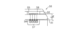
図2(b)に示すように、センサ素子30は、固体電解質層31、拡散抵抗層32、遮蔽層33及び絶縁層34を有し、これらが図の上下に積層されて構成されている。同素子30の周囲には図示しない保護層が設けられている。長方形板状の固体電解質層31(固体電解質体)は部分安定化ジルコニア製のシートであり、その固体電解質層31を挟んで上下一対の排気側電極35及び大気側電極36が対向配置されている。排気側電極35及び大気側電極36は白金Pt等の貴金属により形成されている。拡散抵抗層32は排気側電極35へ排ガスを導入するための多孔質シートからなり、遮蔽層33は排ガスの透過を抑制するための緻密層からなる。拡散抵抗層32には、排気側電極35を囲むようにして排気チャンバ39が形成されている。これら各層32,33は何れも、アルミナ、ジルコニア等のセラミックスをシート成形法等により成形したものであるが、ポロシティの平均孔径及び気孔率の違いによりガス透過率が相違するものとなっている。
As shown in FIG. 2B, the
絶縁層34はアルミナ、ジルコニア等のセラミックスからなり、大気側電極36に対面する部位には大気ダクト37が形成されている。また、同絶縁層34には白金Pt等により形成されたヒータ38が埋設されている。ヒータ38は、バッテリ電源からの通電により発熱する線状の発熱体よりなり、その発熱により素子全体を加熱する。ヒータ38は、絶縁層34に埋設される構成(センサ素子30に内蔵される構成)以外に、センサ素子30に外付けされる構成であってもよい。
The insulating
上記構成のセンサ素子30において、その周囲の排気は拡散抵抗層32の側方部位から導入され、排気側電極35に達する。排気がリーンの場合においてセンサ素子30が活性状態にあると、排気中の酸素が排気側電極35で分解され、大気側電極36より大気ダクト37に排出される。すなわち、大気側電極36側への酸素のポンピングが行われる。そして、大気ダクト37に排出された酸素は、大気空間Sに排出される。また、排気がリッチの場合においてセンサ素子30が活性状態にあると、逆に大気ダクト37内の酸素が大気側電極36で分解され、排気側電極35より排気チャンバ39に排出される。すなわち、排気側電極35側への酸素のポンピングが行われる。
In the
本実施形態では、排気側電極35を負極、大気側電極36を正極としており、図2(b)のように排気側電極35を負(−)、大気側電極36を正(+)としてこれら電極間に印加される印加電圧を正電圧としている。ゆえに、その逆に、排気側電極35を正(+)、排気側電極35を負(−)としてこれら電極間に印加される印加電圧が負電圧である。
In this embodiment, the
図3は、A/Fセンサ20の電圧−電流特性(V−I特性)を示す図面であり、特に大気検出状態での特性を示している。図3において、電圧軸(横軸)に平行で低電圧側の平坦部分はA/Fセンサ20の出力値である素子電流(限界電流)を特定する限界電流域であって、この素子電流の増減が空燃比の増減(すなわち、リーン・リッチの程度)に対応している。つまり、空燃比がリーン側になるほど素子電流は増大し、空燃比がリッチ側になるほど素子電流は減少する。
FIG. 3 is a diagram showing the voltage-current characteristics (VI characteristics) of the A /
一次直線で示されるRGは、センサ素子30への印加電圧の値を決定するための印加電圧線を表している。空燃比を正確に検出するには、印加電圧値をV−I特性の限界電流域上で正しく制御する必要があり、図3の一次直線で示す印加電圧線を設定しておき、この印加電圧線上で、都度の素子電流値に応じて印加電圧値を決定するようにしている。
RG indicated by the primary straight line represents an applied voltage line for determining the value of the applied voltage to the
このV−I特性において、限界電流域よりも低電圧側は抵抗支配域となっており、抵抗支配域における一次直線部分の傾きはセンサ素子30の直流内部抵抗Riにより特定される。直流内部抵抗Riは素子温度に応じて変化し、素子温度が低下すると直流内部抵抗Riが増大する。すなわちこのとき、抵抗支配域の一次直線部分の傾きが小さくなる(直線部分が寝た状態となる)。また、素子温度が上昇すると直流内部抵抗Riが減少する。すなわちこのとき、抵抗支配域の一次直線部分の傾きが大きくなる(直線部分が立った状態となる)。また、このV−I特性において、限界電流域よりも高電圧側の平坦部分は水分解域となっており、この水分解域での電圧印加により排気に含まれる水が分解される。
In this VI characteristic, the lower voltage side than the limit current region is a resistance dominant region, and the slope of the primary straight line portion in the resistance dominant region is specified by the DC internal resistance Ri of the
大気検出状態でのV−I特性においては、センサ素子30に大気検出電圧として電圧V1が印加された状態で、限界電流域において大気での酸素濃度出力が得られる。また、電圧V2は、大気検出状態での限界電流域の上限値に対応する電圧であり、電圧V3は、水分解域の上限値に対応する電圧である。なお、電圧V3以上の電圧がセンサ素子30に印加されると固体電解質層31が黒色化するブラックニングが生じ、固体電解質層31のイオン電導性が低下することに伴う素子劣化が懸念される。電圧V1〜V3は、例えばV1=0.6V、V2=1.1V、V3=1.6Vである。
In the VI characteristic in the atmosphere detection state, an oxygen concentration output in the atmosphere is obtained in the limit current region in a state where the voltage V1 is applied as the atmosphere detection voltage to the
ところで、エンジン停止に伴いA/Fセンサ20の非使用状態に移行した際、すなわち、A/Fセンサ20の出力を使用しない状態に移行した際には、ガスセンサ及びその周辺が高温雰囲気になっており、ケイ素や硫黄、リン、アンモニア、炭化水素、気相状態の金属等の被毒物質を含む大気が大気側電極36側に供給されることにより大気側電極36が被毒することがある。この場合、被毒物質により大気側電極36に絶縁物が形成されるため、その絶縁物により電流が阻害され、A/Fセンサ20の検出精度や応答性が低下する。
By the way, when the A /
具体的には、エンジン停止直後には、走行風が得られなくなる。これにより、エンジン10や排気管14などが有する各種部材が高温状態のままとなり、各種部材から被毒物質を含むアウトガスが発生するとともにそのアウトガスが車両周辺に滞留する。特に、エンジン停止直前の運転状態が高負荷運転状態(例えば、A/Fが12以下、排気圧が150kPa以上等)であった場合には、そのアウトガスは増加する。この場合、センサ素子30の大気ダクト37内は被毒物質が多い被毒環境になるため、その被毒物質により大気側電極36に絶縁物が形成されやすくなる。
Specifically, the running wind cannot be obtained immediately after the engine is stopped. As a result, various members of the
そこで本実施形態では、A/Fセンサ20の出力を使用しない状態に移行した際に、大気側電極36が被毒環境にあると判定された場合に、排気側電極35から大気側電極36に対して酸素のポンピングを実施する。このとき、ECU17は、センサ素子30を所定温度にして活性状態を維持するとともに、センサ素子30の印加電圧を所定の正電圧にする。これにより、図4に示すように、大気側電極36への酸素のポンピングが行われる。大気側電極36への酸素のポンピングが行われると、大気ダクト37内が酸素で充満し、その後、大気空間S内が酸素で充満する。
Therefore, in this embodiment, when it is determined that the
次に、ECU17により実施されるポンピング処理の手順について、図5のフローチャートを用いて説明する。 Next, the procedure of the pumping process performed by ECU17 is demonstrated using the flowchart of FIG.
まず、ステップS11では、イグニッションスイッチ(図示しない)がオフ状態であるか否かを判定する。ステップS11でYESである場合は、ステップS12に進み、被毒環境であるか否かを判定する。このとき、エンジン停止からの経過時間が所定の停止期間Ta内である場合において、エンジン停止直前の運転状態が高負荷運転状態であることに基づいて大気側電極36が被毒環境にあると判定する。なお、エンジン停止から所定期間遡った時点までのエンジン負荷(例えば、アクセル開度)の積算値が所定値以上である場合を高負荷運転状態とするとよい。
First, in step S11, it is determined whether or not an ignition switch (not shown) is in an off state. When YES is determined in the step S11, the process proceeds to a step S12 so as to determine whether or not it is a poisoned environment. At this time, when the elapsed time from the engine stop is within the predetermined stop period Ta, it is determined that the
ステップS12でYESである場合は、ステップS13に進み、ポンピング処理中であるか否かを判定する。ステップS13でNOである場合は、ステップS14に進み、ポンピング処理を開始する。このとき、ヒータ38の加熱によりセンサ素子30を所定の活性温度に維持する。詳しくは、センサ素子30の活性温度を下限温度とし、大気側電極36の被毒物質による被毒の度合が大きくなる温度を上限温度として、その上下限温度の範囲内でヒータ加熱を制御する。具体的には、素子温度を400〜800℃とする。なお、より望ましくは600〜700℃とする。
If “YES” in the step S12, the process proceeds to a step S13 to determine whether or not the pumping process is being performed. If NO in step S13, the process proceeds to step S14 to start the pumping process. At this time, the
また、センサ素子30の印加電圧を大気検出時の印加電圧である電圧V1以上の所定範囲内に維持することで、大気検出時において大気側電極36への酸素のポンピングを行う。具体的には、印加電圧を0.6〜1.6Vとする。特に本実施形態では、大気ダクト37内及び大気空間S内を安定的に酸素で充満させるべく電圧V2を下限電圧とし、ブラックニングが生じる電圧V3を上限電圧として、その上下限電圧の範囲内で電圧を制御する。
Further, by maintaining the applied voltage of the
一方、ステップS13でYESである場合は、ステップS15に進み、ポンピング処理の終了タイミングであるか否かを判定する。このとき、ポンピング処理開始からの経過時間がポンピング時間Tbを経過した場合に、ポンピング処理の終了タイミングであることを判定する。ステップS15でYESである場合は、ステップS16に進み、ポンピング処理を終了する。 On the other hand, if “YES” in the step S13, the process proceeds to a step S15 to determine whether it is the end timing of the pumping process. At this time, when the elapsed time from the start of the pumping process exceeds the pumping time Tb, it is determined that it is the end timing of the pumping process. If YES in step S15, the process proceeds to step S16, and the pumping process is terminated.
以上、詳述した本実施形態によれば、以下の優れた効果が得られる。 As mentioned above, according to this embodiment explained in full detail, the following outstanding effects are acquired.
上記構成によれば、A/Fセンサ20の出力を使用しない状態に移行した際に、大気側電極36が被毒環境にあると判定された場合に、排気側電極35から大気側電極36に対して酸素のポンピングを実施する構成とした。この場合、大気側電極36が設けられている大気ダクト37内が酸素で充満され、大気中に含まれる被毒物質が大気ダクト37内へ流入することが抑制される。これにより、大気側電極36の被毒を適正に抑制できる。また、大気側電極36の表面に被毒防止層を設けることをしなくても、大気側電極36の被毒を抑制でき、大気側電極36の表面に被毒防止層を設けることに起因する検出精度や応答性の低下を回避できる。
According to the above configuration, when it is determined that the
大気側電極36が被毒環境にあると判定された場合に、大気検出時の印加電圧である大気検出電圧として電圧V1以上の所定の印加電圧で大気側電極36側への酸素のポンピングを行う構成とした。この場合、大気ダクト37を酸素で充満させることができる。その結果、大気側電極36が被毒することを好適に抑制することができる。
When it is determined that the atmosphere-
大気側電極36が被毒環境にあると判定された場合に、限界電流域の上限値に対応する電圧V2と、水分解域の上限値に対応する電圧V3との間の所定の印加電圧で酸素のポンピングを行う構成とした。この場合、ブラックニングが発生することを抑制しつつ、大気ダクト37だけでなく大気側カバー24内に設けられた大気空間Sも安定的に酸素で充満させることができる。その結果、ブラックニングが発生することを抑制しつつ、大気側電極36が被毒することの抑制効果を高めることができる。
When it is determined that the atmosphere-
大気側電極36が被毒環境にあると判定された場合に、ヒータ38の加熱によりセンサ素子30を活性状態に維持する構成とした。この場合、酸素のポンピングを安定的に行うことができるため、大気側電極36が被毒することを安定的に抑制することができる。
When it is determined that the
素子温度が高すぎると、却って大気側電極36の被毒物質による被毒が促される懸念が生じる。この点、上限温度を定めてその上限温度以下でヒータ加熱を実施する構成にしたため、大気側電極36の被毒を好適に抑制できる。
If the element temperature is too high, there is a concern that poisoning of the
大気ダクト37内と大気空間S内とを酸素で充満させるようにポンピングを実施する構成とした。このため、大気側電極36の電極表面上を安定的に酸素で充満させることができる。その結果、大気側電極36が被毒することの抑制効果を高めることができる。
Pumping is performed so that the
エンジン停止からの経過時間が停止期間Ta内である場合に、大気側電極36が被毒環境にあると判定する構成にした。このため、エンジン停止により大気側電極36が被毒し易くなる場合であっても、大気側電極36が被毒することを適正に抑制することができる。
When the elapsed time from the engine stop is within the stop period Ta, the
エンジン停止からの経過時間が停止期間Ta内である場合に、エンジン停止直前の運転状態が高負荷運転状態であることに基づいて大気側電極36が被毒環境にあると判定する構成にした。この場合、被毒環境の判定精度を向上させることができるため、ポンピング処理の要否を適正に判断することができる。このため、不要なポンピングによりバッテリ電極が消費されることを抑制しつつ、大気側電極36が被毒することを適正に抑制することができる。
When the elapsed time from the engine stop is within the stop period Ta, the atmosphere-
(他実施形態)
上記の実施形態を例えば次のように変更してもよい。
(Other embodiments)
The above embodiment may be modified as follows, for example.
・イグニッションスイッチがオフ状態であることに基づいて大気側電極36が被毒環境にあると判定する構成としたが、イグニッションスイッチがオン状態であり、かつ車両が停車状態であることに基づいて大気側電極36が被毒環境にあると判定する構成としてもよい。この場合、停車からの経過時間が所定の停車継続時間内である場合において、車両の停車直前の運転状態が高負荷運転状態であった場合に大気側電極36が被毒環境にあると判定するとよい。
The
・エンジン10が高負荷運転状態である場合にセンサ出力に基づく空燃比フィードバック制御が中断されるエンジン制御システムにおいて、その中断が行われた際に大気側電極36が被毒環境にあると判定する構成としてもよい。
In the engine control system in which the air-fuel ratio feedback control based on the sensor output is interrupted when the
エンジン10の高負荷運転時(例えば、A/Fが12以下、排気圧が150kPa以上等)には、被毒物質を含むアウトガスが発生する。また、高負荷運転時には、排気がリッチになり大気ダクト37内の酸素が排気チャンバ39に排出される。この場合、車両が運転状態であっても大気ダクト37内に被毒物質を含むアウトガスが入りやすくなるため、大気側電極36は被毒環境にあると考えられる。この点、上記によれば、エンジン10が高負荷運転状態である場合に、センサ出力に基づく空燃比フィードバック制御が中断された際に、大気側電極36が被毒環境にあると判定され、大気側電極36側に酸素のポンピングが行われる。このため、車両が運転状態である場合であっても、大気側電極36への酸素のポンピングを行う機会を適正に判断することができる。
During high-load operation of the engine 10 (for example, A / F is 12 or less, exhaust pressure is 150 kPa or more, etc.), outgas containing poisonous substances is generated. Further, during high load operation, the exhaust becomes rich and oxygen in the
・大気側電極36が被毒環境にあることを判定するための停止期間Ta又はポンピング処理の終了判定を行うためのポンピング時間Tbを、エンジン停止から所定時間遡った時点までのエンジン負荷(例えばアクセル開度)の積算値に基づいて可変に設定する構成としてもよい。この場合、図6に示すようにエンジン負荷の積算値が大きいほど停止期間Ta又はポンピング時間Tbを大きく設定するとよい。
The engine load (for example, accelerator) for the stop period Ta for determining that the
エンジン負荷の積算値が大きいほどエンジン停止後のアウトガスの発生時間は長くなるとともにその発生量は大きくなることが考えられる。この点、上記構成によれば、エンジン停止時から所定時間遡った時点までのエンジン負荷の積算値が大きいほど、ポンピング時間Tbを大きく設定する構成とした。この場合、アウトガスの発生時間及びその発生量に応じてポンピング時間Tbを変化させることができるため、大気側電極36が被毒することを好適に抑制することができる。
It can be considered that as the integrated value of the engine load is larger, the outgas generation time after the engine is stopped is longer and the generation amount is larger. In this regard, according to the above-described configuration, the pumping time Tb is set to be larger as the integrated value of the engine load from the time when the engine is stopped to a time point that is a predetermined time backward is larger. In this case, since the pumping time Tb can be changed according to the generation time and the generation amount of outgas, it is possible to suitably suppress the
また、エンジン停止時から所定時間遡った時点までのエンジン負荷の積算値が大きいほど、停止期間Taを大きく設定する構成とした。この場合、被毒環境が継続している状態であるか否かが把握されるため、被毒環境の判定精度を高めることができる。 Further, the stop period Ta is set to be larger as the integrated value of the engine load from the time when the engine is stopped to a time point that is a predetermined time later is larger. In this case, since it is grasped whether or not the poisoning environment is continuing, it is possible to improve the determination accuracy of the poisoning environment.
・エンジン水温が所定温度以下に低下した場合に、ポンピング処理を終了する構成としてもよい。 -It is good also as a structure which terminates a pumping process, when an engine water temperature falls below predetermined temperature.
・酸素濃度を検出対象とするA/Fセンサ20やO2センサ以外に、他のガス濃度成分を検出対象とするガスセンサにも本発明が適用できる。例えば、複合型のガスセンサは、固体電解質層にて形成された複数のセルを有し、そのうち第1セル(ポンプセル)では被検出ガス中の酸素を排出又はくみ出すとともに酸素濃度を検出し、第2セル(センサセル)では酸素排出後のガスから特定成分のガス濃度を検出する。このガスセンサは、例えば排ガス中のNOx濃度を検出するNOxセンサとして具体化されるものであり、このNOxセンサを対象とするセンサ制御装置としても具体化できる。また、上記第1セル、第2セルに加え、酸素排出後の残留酸素濃度を検出するための第3セル(モニタセル、若しくは第2ポンプセル)等の複数のセルを有するガスセンサであってもよい。
In addition to the A /
・エンジン10の吸気通路に設けられるガスセンサや、ガソリンエンジン以外にディーゼルエンジンなど、他の形式のエンジンに用いられるガスセンサを対象とするセンサ制御装置としても具体化できる。そのガスセンサは、排気以外のガスを検出対象としたり、自動車以外の用途で用いられるものであってもよい。
-It can also be embodied as a sensor control device for a gas sensor provided in an intake passage of the
・起電力出力型のガスセンサとして、排ガス中の酸素濃度(O2濃度)に応じて電極間で起電力を発生するセンサ以外に、酸素成分を含むNOxやCO等の濃度に応じて電極間で起電力を発生するセンサであっても良い。すなわち、一方の電極でNOxやCOが分解されて酸素イオンが生じ、固体電解質層を挟んで両側で酸素分圧に差が生じると、その酸素分圧の差に応じて起電力が発生する。このとき、ネルンストの式に基づく起電力が発生する。こうした構成のガスセンサについても本発明が適用できる。この場合、酸素分圧に基づいてポンピング処理を終了させる構成としてもよい。 As an electromotive force output type gas sensor, in addition to a sensor that generates an electromotive force between electrodes according to the oxygen concentration (O2 concentration) in the exhaust gas, an electromotive force is generated between the electrodes according to the concentration of NOx or CO containing oxygen components. A sensor that generates electric power may be used. That is, when NOx and CO are decomposed at one electrode to generate oxygen ions and a difference in oxygen partial pressure occurs on both sides of the solid electrolyte layer, an electromotive force is generated according to the difference in oxygen partial pressure. At this time, an electromotive force based on the Nernst equation is generated. The present invention can also be applied to a gas sensor having such a configuration. In this case, the pumping process may be terminated based on the oxygen partial pressure.
17…ECU(センサ制御装置)、20…A/Fセンサ(ガスセンサ)、30…センサ素子、31…固体電解質層、35…排気側電極(ガス側電極)、36…大気側電極、37…大気ダクト。 17 ... ECU (sensor control device), 20 ... A / F sensor (gas sensor), 30 ... sensor element, 31 ... solid electrolyte layer, 35 ... exhaust side electrode (gas side electrode), 36 ... atmosphere side electrode, 37 ... atmosphere duct.
Claims (11)
前記ガスセンサの出力を使用しない状態に移行した際に、前記大気側電極が被毒環境にあるか否かを判定する環境判定部と、
前記大気側電極が被毒環境にあると判定された場合に、前記ガス側電極から前記大気側電極に対して酸素のポンピングを実施するポンピング実施部と、
を有するセンサ制御装置(17)。 It has a sensor element (30) including a solid electrolyte layer (31) and a pair of electrodes (35, 36) provided on both sides of the solid electrolyte layer, and one of the pair of electrodes is a gas to be detected. Is applied to the gas sensor (20), which is an atmosphere side electrode (36) provided in an air duct (37) into which air is introduced from the outside.
An environment determination unit that determines whether or not the atmosphere side electrode is in a poisoned environment when the gas sensor output is shifted to a non-use state;
A pumping execution unit that performs oxygen pumping from the gas side electrode to the atmosphere side electrode when it is determined that the atmosphere side electrode is in a poisoned environment;
A sensor control device (17).
前記ポンピング実施部は、前記大気側電極が被毒環境にあると判定された場合に、大気検出時の印加電圧である大気検出電圧又はそれよりも高い電圧側の所定電圧を前記一対の電極に印加して、前記ガス側電極から前記大気側電極に対して酸素のポンピングを実施する請求項1に記載のセンサ制御装置。 The gas sensor is a limiting current type gas concentration sensor configured to flow an element current according to an oxygen concentration each time a predetermined voltage is applied to the pair of electrodes.
When it is determined that the atmosphere-side electrode is in a poisoned environment, the pumping unit applies an atmospheric detection voltage, which is an applied voltage at the time of atmospheric detection, or a predetermined voltage on a higher voltage side to the pair of electrodes. The sensor control apparatus according to claim 1, wherein the pumping of oxygen is performed from the gas side electrode to the atmosphere side electrode by applying.
前記ポンピング実施部は、前記大気側電極が被毒環境にあると判定された場合に、限界電流域の上限値に対応する第1電圧と、前記第1電圧よりも高い電圧であり水分解域の上限値に対応する第2電圧との間の所定電圧を前記一対の電極に印加して、前記ガス側電極から前記大気側電極に対して酸素のポンピングを実施する請求項1又は2に記載のセンサ制御装置。 The gas sensor is a limiting current type gas concentration sensor configured to flow an element current according to an oxygen concentration each time a predetermined voltage is applied to the pair of electrodes.
The pumping unit, when it is determined that the atmosphere side electrode is in a poisoned environment, a first voltage corresponding to an upper limit value of a limit current region, a voltage higher than the first voltage, and a water decomposition region 3. The pumping of oxygen is performed from the gas side electrode to the atmosphere side electrode by applying a predetermined voltage between the second voltage corresponding to the upper limit value of the gas to the pair of electrodes. Sensor control device.
前記大気側電極が被毒環境にあると判定された場合に、前記ヒータの加熱により前記センサ素子を活性状態に維持するヒータ制御部を備える請求項1乃至3のいずれか1項に記載のセンサ制御装置。 The gas sensor includes a heater (38) for heating the sensor element,
4. The sensor according to claim 1, further comprising a heater control unit configured to maintain the sensor element in an active state by heating the heater when it is determined that the atmosphere-side electrode is in a poisoned environment. Control device.
前記ポンピング実施部は、前記ガスセンサにおいて前記大気ダクトと前記内部空間とを酸素で充満させるように前記ポンピングを実施する請求項1乃至5のいずれか1項に記載のセンサ制御装置。 The gas sensor has an atmosphere side cover part (24) provided with an introduction port (28) for accommodating the sensor element and introducing the atmosphere into the internal space (S), and the atmosphere introduced from the introduction port is It has a configuration that flows into the air duct from an internal space,
6. The sensor control device according to claim 1, wherein the pumping unit performs the pumping so that the atmospheric duct and the internal space are filled with oxygen in the gas sensor. 7.
前記環境判定部は、前記エンジンの運転停止直後の所定の停止期間内である場合に前記大気側電極が被毒環境にあると判定する請求項1乃至6のいずれか1項に記載のセンサ制御装置。 The gas sensor is an exhaust sensor that detects the concentration of a specific component in the exhaust with the exhaust discharged from the in-vehicle engine (10) as a detection target,
The sensor control according to any one of claims 1 to 6, wherein the environment determination unit determines that the atmosphere-side electrode is in a poisoned environment when it is within a predetermined stop period immediately after the operation of the engine is stopped. apparatus.
前記酸素濃度の検出結果に基づいて空燃比フィードバック制御を実施し、前記エンジンが高負荷運転状態である場合に、前記空燃比フィードバック制御を中断する制御システムに適用され、
前記環境判定部は、前記空燃比フィードバック制御が中断されたことにより前記ガスセンサの出力を使用しない状態に移行した際に、前記大気側電極が被毒環境にあると判定する請求項1乃至10のいずれか1項に記載のセンサ制御装置。 The gas sensor is an exhaust sensor that detects the oxygen concentration in the exhaust gas with the exhaust gas discharged from the in-vehicle engine (10) as a detection target,
Applied to a control system that performs air-fuel ratio feedback control based on the detection result of the oxygen concentration and interrupts the air-fuel ratio feedback control when the engine is in a high-load operation state,
The said environment determination part determines that the said atmosphere side electrode exists in poisonous environment, when it transfers to the state which does not use the output of the said gas sensor by the said air-fuel ratio feedback control being interrupted. The sensor control device according to any one of claims.
Priority Applications (2)
| Application Number | Priority Date | Filing Date | Title |
|---|---|---|---|
| JP2015202101A JP6455389B2 (en) | 2015-10-13 | 2015-10-13 | Sensor control device |
| DE102016119379.8A DE102016119379A1 (en) | 2015-10-13 | 2016-10-12 | Sensor control device which is adapted for a gas sensor which detects a poisoning environment |
Applications Claiming Priority (1)
| Application Number | Priority Date | Filing Date | Title |
|---|---|---|---|
| JP2015202101A JP6455389B2 (en) | 2015-10-13 | 2015-10-13 | Sensor control device |
Publications (2)
| Publication Number | Publication Date |
|---|---|
| JP2017075794A JP2017075794A (en) | 2017-04-20 |
| JP6455389B2 true JP6455389B2 (en) | 2019-01-23 |
Family
ID=58405850
Family Applications (1)
| Application Number | Title | Priority Date | Filing Date |
|---|---|---|---|
| JP2015202101A Active JP6455389B2 (en) | 2015-10-13 | 2015-10-13 | Sensor control device |
Country Status (2)
| Country | Link |
|---|---|
| JP (1) | JP6455389B2 (en) |
| DE (1) | DE102016119379A1 (en) |
Families Citing this family (1)
| Publication number | Priority date | Publication date | Assignee | Title |
|---|---|---|---|---|
| JP7247989B2 (en) * | 2020-07-31 | 2023-03-29 | 株式会社デンソー | sensor controller |
Family Cites Families (7)
| Publication number | Priority date | Publication date | Assignee | Title |
|---|---|---|---|---|
| JPS6276449A (en) * | 1985-09-30 | 1987-04-08 | Honda Motor Co Ltd | Method for controlling oxygen concentration sensor |
| JPH04215059A (en) * | 1990-10-15 | 1992-08-05 | Ngk Spark Plug Co Ltd | Oxygen sensor and manufacture thereof |
| JP4440822B2 (en) | 1999-10-27 | 2010-03-24 | 日本特殊陶業株式会社 | Oxygen sensor |
| DE10043089C2 (en) * | 2000-09-01 | 2003-02-27 | Bosch Gmbh Robert | gas sensor |
| WO2012086079A1 (en) * | 2010-12-24 | 2012-06-28 | トヨタ自動車株式会社 | Oxygen sensor and oxygen sensor control device |
| US20130036795A1 (en) * | 2011-08-08 | 2013-02-14 | Ngk Spark Plug Co., Ltd. | Gas sensor |
| JP6401644B2 (en) * | 2014-03-31 | 2018-10-10 | 日本碍子株式会社 | Gas sensor |
-
2015
- 2015-10-13 JP JP2015202101A patent/JP6455389B2/en active Active
-
2016
- 2016-10-12 DE DE102016119379.8A patent/DE102016119379A1/en active Pending
Also Published As
| Publication number | Publication date |
|---|---|
| DE102016119379A1 (en) | 2017-04-13 |
| JP2017075794A (en) | 2017-04-20 |
Similar Documents
| Publication | Publication Date | Title |
|---|---|---|
| US9903292B2 (en) | Abnormality diagnosis system of air-fuel ratio sensor | |
| KR101781278B1 (en) | Control device for internal combustion engine | |
| JPWO2014118892A1 (en) | Control device for internal combustion engine | |
| KR101442391B1 (en) | Emission control system for internal combustion engine | |
| CN110672698B (en) | Gas sensor and sensor element | |
| JP7261053B2 (en) | Gas sensor and sensor element | |
| US20220113280A1 (en) | Gas sensor | |
| JP5949958B2 (en) | Control device for internal combustion engine | |
| US10473049B2 (en) | Control system of internal combustion engine | |
| JP2020159881A (en) | Gas sensor and sensor element | |
| JP6255948B2 (en) | Gas sensor control device | |
| JP6551314B2 (en) | Gas sensor controller | |
| JP6455389B2 (en) | Sensor control device | |
| JP6562047B2 (en) | Exhaust gas purification device for internal combustion engine | |
| US11078858B2 (en) | Control apparatus for an internal combustion engine | |
| WO2014118888A1 (en) | Control device for internal combustion engine | |
| US10180111B2 (en) | Gas sensor control device | |
| JP6733648B2 (en) | Catalyst deterioration detector | |
| JP4556504B2 (en) | Concentration detector | |
| JP6065888B2 (en) | Air-fuel ratio sensor abnormality diagnosis device | |
| JP2018189502A (en) | Gas concentration detector | |
| JP2024132120A (en) | Concentration information acquisition device and concentration information acquisition method | |
| JP2018004349A (en) | Gas sensor | |
| JP2020197201A (en) | Air-fuel ratio detection system | |
| JP2018059941A (en) | Gas sensor control device |
Legal Events
| Date | Code | Title | Description |
|---|---|---|---|
| A621 | Written request for application examination |
Free format text: JAPANESE INTERMEDIATE CODE: A621 Effective date: 20180117 |
|
| A977 | Report on retrieval |
Free format text: JAPANESE INTERMEDIATE CODE: A971007 Effective date: 20181108 |
|
| TRDD | Decision of grant or rejection written | ||
| A01 | Written decision to grant a patent or to grant a registration (utility model) |
Free format text: JAPANESE INTERMEDIATE CODE: A01 Effective date: 20181120 |
|
| A61 | First payment of annual fees (during grant procedure) |
Free format text: JAPANESE INTERMEDIATE CODE: A61 Effective date: 20181203 |
|
| R151 | Written notification of patent or utility model registration |
Ref document number: 6455389 Country of ref document: JP Free format text: JAPANESE INTERMEDIATE CODE: R151 |
|
| R250 | Receipt of annual fees |
Free format text: JAPANESE INTERMEDIATE CODE: R250 |
|
| R250 | Receipt of annual fees |
Free format text: JAPANESE INTERMEDIATE CODE: R250 |
|
| R250 | Receipt of annual fees |
Free format text: JAPANESE INTERMEDIATE CODE: R250 |
|
| R250 | Receipt of annual fees |
Free format text: JAPANESE INTERMEDIATE CODE: R250 |