JP5108638B2 - Piping prevention device - Google Patents
Piping prevention device Download PDFInfo
- Publication number
- JP5108638B2 JP5108638B2 JP2008149291A JP2008149291A JP5108638B2 JP 5108638 B2 JP5108638 B2 JP 5108638B2 JP 2008149291 A JP2008149291 A JP 2008149291A JP 2008149291 A JP2008149291 A JP 2008149291A JP 5108638 B2 JP5108638 B2 JP 5108638B2
- Authority
- JP
- Japan
- Prior art keywords
- stopper
- outer tube
- tube
- inner tube
- engaging
- Prior art date
- Legal status (The legal status is an assumption and is not a legal conclusion. Google has not performed a legal analysis and makes no representation as to the accuracy of the status listed.)
- Active
Links
- 230000002265 prevention Effects 0.000 title claims description 7
- 238000003780 insertion Methods 0.000 claims description 65
- 230000037431 insertion Effects 0.000 claims description 65
- 230000003014 reinforcing effect Effects 0.000 claims description 12
- 238000005452 bending Methods 0.000 description 26
- 238000003466 welding Methods 0.000 description 7
- 230000009194 climbing Effects 0.000 description 5
- 238000002485 combustion reaction Methods 0.000 description 4
- 239000002803 fossil fuel Substances 0.000 description 3
- 238000010438 heat treatment Methods 0.000 description 3
- 239000002184 metal Substances 0.000 description 3
- XLYOFNOQVPJJNP-UHFFFAOYSA-N water Substances O XLYOFNOQVPJJNP-UHFFFAOYSA-N 0.000 description 3
- 230000000694 effects Effects 0.000 description 2
- 238000000605 extraction Methods 0.000 description 2
- 229910001220 stainless steel Inorganic materials 0.000 description 2
- 239000010935 stainless steel Substances 0.000 description 2
- 238000009423 ventilation Methods 0.000 description 2
- 229910000906 Bronze Inorganic materials 0.000 description 1
- OAICVXFJPJFONN-UHFFFAOYSA-N Phosphorus Chemical compound [P] OAICVXFJPJFONN-UHFFFAOYSA-N 0.000 description 1
- 230000001154 acute effect Effects 0.000 description 1
- 238000013459 approach Methods 0.000 description 1
- 239000010974 bronze Substances 0.000 description 1
- 238000010276 construction Methods 0.000 description 1
- KUNSUQLRTQLHQQ-UHFFFAOYSA-N copper tin Chemical compound [Cu].[Sn] KUNSUQLRTQLHQQ-UHFFFAOYSA-N 0.000 description 1
- 239000000463 material Substances 0.000 description 1
- 238000012986 modification Methods 0.000 description 1
- 230000004048 modification Effects 0.000 description 1
- 230000000149 penetrating effect Effects 0.000 description 1
- 238000003825 pressing Methods 0.000 description 1
- 238000004080 punching Methods 0.000 description 1
- 230000002787 reinforcement Effects 0.000 description 1
- 230000000630 rising effect Effects 0.000 description 1
- 238000009751 slip forming Methods 0.000 description 1
Images


Landscapes
- Mutual Connection Of Rods And Tubes (AREA)
- Quick-Acting Or Multi-Walled Pipe Joints (AREA)
Description
本発明は、暖房用及び給湯用機器としてガスや化石燃料を用いた機器に接続される配管の抜け止め装置に関するものである。 The present invention relates to an apparatus for preventing a pipe connected to an apparatus using gas or fossil fuel as an apparatus for heating and hot water supply.
従来より暖房用や給湯用機器などには比較的熱効率が高いガスや化石燃料などが使用された燃焼機器が広く用いられてきている。近年では住宅の室内も高気密化してきており、このような燃焼機器の室内使用においては、充分な換気を行わなければならない。特に寒い北国の家屋や建物については長時間に渡ってそれらの機器を使用しなければならず、室内換気の重要性は極めて高いものである。 Conventionally, combustion equipment using gas or fossil fuel with relatively high thermal efficiency has been widely used for heating and hot water supply equipment. In recent years, the interior of houses has become highly airtight, and sufficient ventilation must be provided for the indoor use of such combustion equipment. Especially in cold northern homes and buildings, these devices must be used for a long time, and the importance of indoor ventilation is extremely high.
係る燃焼機器には外気の導入や給排気用の配管(給排気管)として、単配管或いは二重配管が、予め一定の長さに製作されたものを複数本接続して延長しているのが一般的である。このような施工方法で配管を延長した場合、何れかの接続部が外れて配管が抜け落ちたりしないように、通常各配管の接続部毎に配管の抜け止め装置が設けられている。 Such combustion equipment is extended by connecting a plurality of single pipes or double pipes that have been manufactured in advance to a certain length as pipes for supplying and exhausting outside air (supply and exhaust pipes). Is common. When a pipe is extended by such a construction method, a pipe retaining device is usually provided for each connecting part of each pipe so that any connecting part is not detached and the pipe is not dropped.
このような燃焼機器に設けられた配管の抜け止め装置として、一方の配管(外管)の受け口内に他の配管(内管)の挿入口側が差し込まれると、ロック部が挿入口の先端で押し上げられて、切り窓から当該切り窓の外に溶接固定され、逃げ空間とロック壁及びスライドガイドを形成したカバー内(逃げ空間)に収まる。更に内管の挿入口側が外管の受け口内に差し込まれると、ロック部の下に内管に形成した円周溝が合い、ロック部材の弾性作用でロック部が円周溝内に落ち込み内管と外管とがロックされる。 As a piping retaining device provided in such a combustion device, when the insertion port side of the other piping (inner tube) is inserted into the receiving port of one piping (outer tube), the lock part is at the tip of the insertion port. It is pushed up, welded and fixed from the cut window to the outside of the cut window, and fits in the escape space, the cover that forms the lock wall and the slide guide (the escape space). Further, when the inner tube insertion port side is inserted into the outer tube receiving port, the circumferential groove formed in the inner tube fits under the lock portion, and the lock portion falls into the circumferential groove by the elastic action of the lock member, and the inner tube And the outer tube are locked.
そして、内管と外管とに引き抜き方向の力が加わったとき、係合部がロック壁で押さえられ、これによりロック部にくさび効果が作用して、円周溝との嵌合関係が強化される。これにより、内管と外管とが接続部で抜け落ちてしまうのを防止していた。また、内管と外管と引き抜いて外す場合には、挿入口側を一旦押し込んで一緒にロック部材を後退させてロック部の係合部をロック壁から逃げ空間側に逃がす。そして、この状態で、ロック部材のストッパ操作部を指先で押さえ、挿入口側を引くことにより、ロック部が円周溝の縁に沿って持ち上げられて切り窓から逃げ空間内に収まり、そのまま両配管を相互に離間させることにより引き抜けるように構成していた。これにより、内管と外管とを容易に着脱できるように構成していた(特許文献1参照)。
しかしながら、内管と外管とを接続する従来の配管の抜け止め装置は、カバーを外管に溶接固定してからでは、スライドガイドと外管との隙間にロック部材を挿入することができなかった。そこで、スライドガイドと外管との隙間にロック部材を挿入した後、カバーを外管に溶接固定していた。このため、ロック部材が変形して、抜け止め装置の役割を果たさない場合には、外管から溶接したカバーを外し、再度ロック部材をスライドガイドと外管との隙間に挿入した後、カバーを外管に溶接固定しなければならないという手間のかかる問題があった。 However, the conventional piping retaining device for connecting the inner pipe and the outer pipe cannot insert the lock member into the gap between the slide guide and the outer pipe after the cover is welded and fixed to the outer pipe. It was. Therefore, after inserting the lock member into the gap between the slide guide and the outer tube, the cover is welded and fixed to the outer tube. For this reason, when the lock member is deformed and does not serve as a retaining device, the welded cover is removed from the outer tube, the lock member is inserted again into the gap between the slide guide and the outer tube, and then the cover is removed. There was a troublesome problem that the outer tube had to be fixed by welding.
本発明は、係る従来技術の課題を解決するために成されたものであり、溶接固定をしなくても簡単にストッパの着脱を行うことができ、且つ、内管と外管との着脱が容易に行うことができる配管の抜け止め装置を提供することを目的とする。 The present invention has been made to solve the problems of the related art. The stopper can be easily attached / detached without fixing by welding, and the inner tube and the outer tube can be attached / detached. An object of the present invention is to provide a piping retaining device that can be easily performed.
即ち、本発明の配管の抜け止め装置は、外管と、該外管の一端より当該外管内に挿入される内管と、外管の一端近傍に構成され、当該外管の半径方向外側に突出する突出部と、内管の外管内に挿入される側の端部に形成され、該内管の半径方向内側に陥没する凹陥部と、突出部に対応して外管に取り付けられる弾性を有したストッパとを備え、突出部は、低突出部と、該低突出部の外管一端側の側面に形成された挿入孔と、低突出部の外管一端側とは反対側に連続する高突出部と、低突出部に形成された突出部側係合部と、該突出部側係合部の高突出部側に位置して低突出部より高く突出する乗り上げ部とを有し、ストッパは、外辺と、該外辺一端の屈曲部にて連続して折り返された内辺と、該内辺の他端に構成された第1の係合部と、該第1の係合部よりも屈曲部側に位置して形成された第2の係合部とを有し、内辺が突出部の挿入孔から当該突出部内に進入し、外辺と内辺により突出部を挟んだ状態で外管に取り付けられ、外管より内管を引き抜く方向に当該内管が移動した場合、ストッパの内辺他端の第1の係合部が内管の凹陥部に係合し、且つ、第2の係合部が突出部の突出部側係合部に係合することで引き抜きが阻止されると共に、突出部の高突出部に内管の凹陥部が対応した状態で、外辺の他端が突出部の乗り上げ部に乗り上げる方向にストッパが移動された場合、該ストッパの内辺他端の第1の係合部は内管の凹陥部より離脱することを特徴とする。 That is, the pipe retaining device according to the present invention includes an outer tube, an inner tube inserted into the outer tube from one end of the outer tube, and one end of the outer tube. Protruding protrusions, a recess formed at the end of the inner tube that is inserted into the outer tube, and recessed inward in the radial direction of the inner tube, and an elasticity attached to the outer tube corresponding to the protruding portion. The protrusion has a low protrusion, an insertion hole formed in a side surface of the low protrusion on the one end side of the outer tube, and a side opposite to the one end of the outer tube of the low protrusion. A high projecting portion, a projecting portion side engaging portion formed in the low projecting portion, and a riding portion that is located on the high projecting portion side of the projecting portion side engaging portion and projects higher than the low projecting portion, The stopper includes an outer side, an inner side continuously folded at a bent portion at one end of the outer side, a first engaging portion configured at the other end of the inner side, A second engaging portion formed on the bent portion side of the engaging portion, and the inner side enters the protruding portion from the insertion hole of the protruding portion, and protrudes by the outer side and the inner side. When the inner tube moves in the direction in which the inner tube is pulled out from the outer tube, the first engaging portion at the other end of the inner side of the stopper is engaged with the recessed portion of the inner tube. And the second engaging portion is engaged with the protruding portion side engaging portion of the protruding portion to prevent the pulling out, and the concave portion of the inner tube corresponds to the high protruding portion of the protruding portion. Then, when the stopper is moved in the direction in which the other end of the outer side rides on the riding part of the protrusion, the first engaging part at the other end of the inner side of the stopper is disengaged from the recessed part of the inner tube. And
また、請求項2の発明の配管の抜け止め装置は、上記において、突出部の突出部側係合部は、低突出部の上面に形成された係合孔であり、ストッパの第2の係合部は、外辺より内辺側に突出する係合辺であって、外管より内管を引き抜く方向に当該内管が移動した場合、ストッパの係合辺が突出部の係合孔内に進入して係合することを特徴とする。 Further, in the pipe retaining device according to the second aspect of the present invention, in the above, the protruding portion side engaging portion of the protruding portion is an engaging hole formed in the upper surface of the low protruding portion, and the second engagement of the stopper. The joint portion is an engagement side that protrudes inward from the outer side. When the inner tube moves in a direction in which the inner tube is pulled out from the outer tube, the engagement side of the stopper is in the engagement hole of the protrusion. It is characterized by entering and engaging.
また、請求項3の発明の配管の抜け止め装置は、請求項2に加えて、ストッパは、外辺の他端部に形成され、先端側が内辺から離間する方向に傾斜した傾斜部と、内辺の他端部に形成され、外辺側に湾曲して先端が第1の係合部となる湾曲部とを有し、傾斜部が突出部の乗り上げ部に乗り上げる方向にストッパが移動された場合、湾曲部が高突出部の外管一端側の壁の内面に当接しながら当該高突出部内側に進入し、第1の係合部が凹陥部より離脱すると共に、高突出部の外管一端側の壁とストッパの傾斜部は、当該傾斜部の先端に向かう程、相互に離間することを特徴とする。 Further, in addition to claim 2, the pipe retaining device according to the invention of claim 3 is formed at the other end portion of the outer side, and the inclined portion inclined in the direction in which the tip side is separated from the inner side, The stopper is moved in a direction to be formed on the other end portion of the inner side, having a curved portion that curves to the outer side and has a tip that becomes the first engaging portion, and the inclined portion rides on the riding portion of the protruding portion. In this case, the curved portion enters the inside of the high protruding portion while contacting the inner surface of the wall on one end side of the outer tube of the high protruding portion, the first engaging portion is detached from the recessed portion, and the outside of the high protruding portion is The wall on the one end side of the tube and the inclined portion of the stopper are separated from each other toward the tip of the inclined portion.
また、請求項4の発明の配管の抜け止め装置は、請求項1において、突出部の突出部側係合部は、低突出部に凹陥形成された係合凹部であり、ストッパの第2の係合部は、内辺に形成された透孔であって、外管より内管を引き抜く方向に当該内管が移動した場合、突出部の係合凹部がストッパの透孔内に進入して係合することを特徴とする。 According to a fourth aspect of the present invention, there is provided the pipe retaining device according to the first aspect, wherein the protrusion-side engagement portion of the protrusion is an engagement recess formed as a recess in the low protrusion, The engaging portion is a through hole formed on the inner side. When the inner tube moves in a direction in which the inner tube is pulled out from the outer tube, the engaging concave portion of the protruding portion enters the through hole of the stopper. It is characterized by engaging.
また、請求項5の発明の配管の抜け止め装置は、請求項4において、ストッパは、外辺の他端部に形成され、先端側が内辺から離間する方向に傾斜した傾斜部と、該傾斜部の屈曲部側の外辺に形成され、内辺側に突出する突部とを有することを特徴とする。 According to a fifth aspect of the present invention, there is provided the pipe retaining device according to the fourth aspect, wherein the stopper is formed at the other end of the outer side, and the inclined portion is inclined in a direction in which the tip side is separated from the inner side. And a protruding portion that is formed on the outer side of the bent portion side and protrudes toward the inner side.
また、請求項6の発明の配管の抜け止め装置は、請求項4又は請求項5において、ストッパは、内辺の他端部に形成され、外辺側に湾曲して先端が第1の係合部となる湾曲部を有し、ストッパの透孔は湾曲部の屈曲部側の面まで延在しており、該透孔両側に位置する湾曲部の外辺とは反対側の面には、補強リブが形成されていることを特徴とする。 According to a sixth aspect of the present invention, in the pipe retaining device according to the fourth or fifth aspect, the stopper is formed at the other end of the inner side and is curved toward the outer side so that the tip is the first engagement. It has a curved part that becomes a joint part, and the through hole of the stopper extends to the surface on the bent part side of the curved part, and on the surface opposite to the outer side of the curved part located on both sides of the through hole A reinforcing rib is formed.
また、請求項7の発明の配管の抜け止め装置は、請求項1乃至請求項6の何れかにおいて、ストッパの屈曲部は湾曲していると共に、外管の挿入孔下縁には、当該外管の半径方向外側に突出する断面円弧状の案内部が形成され、外辺の他端が突出部の乗り上げ部に乗り上げる方向にストッパが移動された場合、当該ストッパの屈曲部が案内部の外管一端側とは反対側の湾曲面に対応することを特徴とする。 According to a seventh aspect of the present invention, there is provided the piping retaining device according to any one of the first to sixth aspects, wherein the bent portion of the stopper is curved, and the outer edge of the insertion hole of the outer tube is provided on the outer edge of the outer tube. When a guide portion having an arcuate cross section that protrudes outward in the radial direction of the tube is formed and the stopper is moved in a direction in which the other end of the outer side rides on the riding portion of the protruding portion, the bent portion of the stopper is outside the guide portion. It corresponds to the curved surface opposite to the one end side of the tube.
また、請求項8の発明の配管の抜け止め装置は、請求項1乃至請求項7の何れかにおいて、突出部は、外管と一体に突出形成されていると共に、凹陥部は内管の全周に渡って連続して形成されていることを特徴とする。 According to an eighth aspect of the present invention, there is provided the piping retaining device according to any one of the first to seventh aspects, wherein the projecting portion is formed integrally with the outer tube, and the recessed portion is the entire inner tube. It is characterized by being formed continuously over the circumference.
本発明によれば、外管と、該外管の一端より当該外管内に挿入される内管と、外管の一端近傍に構成され、当該外管の半径方向外側に突出する突出部と、内管の外管内に挿入される側の端部に形成され、該内管の半径方向内側に陥没する凹陥部と、突出部に対応して外管に取り付けられる弾性を有したストッパとを備え、突出部は、低突出部と、該低突出部の外管一端側の側面に形成された挿入孔と、低突出部の外管一端側とは反対側に連続する高突出部と、低突出部に形成された突出部側係合部と、該突出部側係合部の高突出部側に位置して低突出部より高く突出する乗り上げ部とを有し、ストッパは、外辺と、該外辺一端の屈曲部にて連続して折り返された内辺と、該内辺の他端に構成された第1の係合部と、該第1の係合部よりも屈曲部側に位置して形成された第2の係合部とを有し、内辺が突出部の挿入孔から当該突出部内に進入し、外辺と内辺により突出部を挟んだ状態で外管に取り付けられ、外管より内管を引き抜く方向に当該内管が移動した場合、ストッパの内辺他端の第1の係合部が内管の凹陥部に係合し、且つ、第2の係合部が突出部の突出部側係合部に係合することで引き抜きが阻止されると共に、突出部の高突出部に内管の凹陥部が対応した状態で、外辺の他端が突出部の乗り上げ部に乗り上げる方向にストッパが移動された場合、該ストッパの内辺他端の第1の係合部は内管の凹陥部より離脱するので、例えば、請求項2の如く、突出部の突出部側係合部は、低突出部の上面に形成された係合孔であり、ストッパの第2の係合部は、外辺より内辺側に突出する係合辺であって、外管より内管を引き抜く方向に当該内管が移動した場合、ストッパの係合辺が突出部の係合孔内に進入して係合するので、外管から内管が抜けてしまうのを確実に防止することができる。これにより、従来のロック部材のようにストッパが変形して配管の抜け止め装置の役割を果たさない場合に、外管から溶接したカバーを外し、再度ロック部材をスライドガイドと外管との隙間に挿入した後、カバーを外管に溶接固定するなどといった煩雑な手間が掛かることがない。従って、ストッパが変形した場合、傾斜部を手で持ち上げて係合辺を係合孔から離脱させ、外管の一端方向に移動させるだけでストッパを取り外して交換することができ、配管の抜け止め装置の利便性を大幅に向上させることができるようになるものである。 According to the present invention, an outer tube, an inner tube that is inserted into the outer tube from one end of the outer tube, a protrusion that is configured near one end of the outer tube and protrudes radially outward of the outer tube, The inner tube includes a recessed portion that is formed at an end portion of the inner tube that is inserted into the outer tube and is recessed radially inward of the inner tube, and a stopper having elasticity that is attached to the outer tube corresponding to the protruding portion. The protruding portion includes a low protruding portion, an insertion hole formed on a side surface of the low protruding portion on one end side of the outer tube, a high protruding portion continuous on the side opposite to the outer tube one end side of the low protruding portion, A protrusion portion engaging portion formed in the protrusion portion, and a riding portion that is located on the high protrusion portion side of the protrusion portion side engagement portion and protrudes higher than the low protrusion portion, and the stopper includes an outer side , An inner side continuously folded at a bent portion at one end of the outer side, a first engaging portion configured at the other end of the inner side, and bent more than the first engaging portion A second engaging portion formed on the side, the inner side enters the protruding portion from the insertion hole of the protruding portion, and the outer tube is sandwiched between the outer side and the inner side. When the inner tube moves in a direction in which the inner tube is pulled out from the outer tube, the first engagement portion at the other end of the inner side of the stopper is engaged with the recessed portion of the inner tube, and the second Pulling out is prevented by engaging the engaging portion with the protruding portion side engaging portion of the protruding portion, and the other end of the outer side is in a state where the recessed portion of the inner tube corresponds to the high protruding portion of the protruding portion. When the stopper is moved in the direction of riding on the riding part of the protruding part, the first engaging part at the other end of the inner side of the stopper is separated from the recessed part of the inner tube. The protruding portion side engaging portion of the portion is an engaging hole formed on the upper surface of the low protruding portion, and the second engaging portion of the stopper protrudes from the outer side to the inner side. When the inner tube moves in a direction in which the inner tube is pulled out from the outer tube, the engaging side of the stopper enters the engagement hole of the protrusion and engages. It is possible to reliably prevent the inner tube from coming off. This prevents the welded cover from being removed from the outer tube when the stopper is deformed and does not serve as a pipe retainer as in the case of the conventional lock member, and the lock member is again inserted into the gap between the slide guide and the outer tube. After the insertion, there is no troublesome work such as welding and fixing the cover to the outer tube. Therefore, when the stopper is deformed, the stopper can be removed and replaced simply by lifting the inclined part by hand to disengage the engaging side from the engaging hole and moving it toward one end of the outer tube. The convenience of the apparatus can be greatly improved.
また、請求項3の発明によれば、ストッパは、外辺の他端部に形成され、先端側が内辺から離間する方向に傾斜した傾斜部と、内辺の他端部に形成され、外辺側に湾曲して先端が第1の係合部となる湾曲部とを有し、傾斜部が突出部の乗り上げ部に乗り上げる方向にストッパが移動された場合、湾曲部が高突出部の外管一端側の壁の内面に当接しながら当該高突出部内側に進入し、第1の係合部が凹陥部より離脱すると共に、高突出部の外管一端側の壁とストッパの傾斜部は、当該傾斜部の先端に向かう程、相互に離間するので、外辺と内辺とを近接させようとするストッパの弾性力により、ストッパは傾斜部が乗り上げ部から降下し、且つ、湾曲部が高突出部内側から外管一端側に離脱する方向に自動的に移動させることができる。これにより、ストッパを外管に取り付けた状態で、当該ストッパの内辺先端の係合部を内管の凹陥部に確実に係合させることができるので、外管内に内管を差し込むだけで、ストッパは確実に抜け止め機能を奏するようになる。 According to the invention of claim 3, the stopper is formed at the other end portion of the outer side, and is formed at the inclined portion whose tip side is inclined in the direction away from the inner side and the other end portion of the inner side, When the stopper is moved in the direction in which the inclined part rides on the riding part of the protruding part, the curved part is outside the high protruding part. While coming into contact with the inner surface of the wall on the one end side of the tube, the inside of the high projecting portion enters, the first engaging portion is detached from the recessed portion, and the wall on the one end side of the outer tube of the high projecting portion and the inclined portion of the stopper As the tip of the inclined portion is further away from each other, the stopper is lowered from the riding portion by the elastic force of the stopper that attempts to bring the outer side and the inner side closer, and the curved portion is It can be automatically moved in the direction of detaching from the inner side of the high protrusion to the one end side of the outer tube. Thereby, in a state where the stopper is attached to the outer tube, the engaging portion of the inner side tip of the stopper can be reliably engaged with the recessed portion of the inner tube, so just by inserting the inner tube into the outer tube, The stopper surely functions to prevent it from coming off.
特に、ストッパの傾斜部は、当該傾斜部の先端に向かう程、相互に離間するようにしているので、ストッパの湾曲部が外管の他端方向で止まってしまうのを防止し、外管の一端方向に位置させておくことができると共に、第1の係合部を常時凹陥部に係合させておくことが可能となる。これにより、第1の係合部が内管の凹陥部に係合しない、或いは、第1の係合部が内管の凹陥部から離脱してしまうのを未然に防止することが可能となる。従って、外管内に挿入した内管が抜けてしまうなどといった不都合を確実に防止することができる。 In particular, since the inclined portions of the stopper are separated from each other toward the tip of the inclined portion, it is possible to prevent the curved portion of the stopper from stopping in the other end direction of the outer tube. While being able to position in one end direction, it becomes possible to always make the 1st engaging part engage with a recessed part. As a result, it is possible to prevent the first engaging portion from engaging with the recessed portion of the inner tube or the first engaging portion from being detached from the recessed portion of the inner tube. . Therefore, it is possible to reliably prevent inconveniences such as the inner tube inserted into the outer tube coming out.
また、請求項4の発明によれば、突出部の突出部側係合部は、低突出部に凹陥形成された係合凹部であり、ストッパの第2の係合部は、内辺に形成された透孔であって、外管より内管を引き抜く方向に当該内管が移動した場合、突出部の係合凹部がストッパの透孔内に進入して係合するので、係合凹部と透孔間のストッパ寸法を極めて短寸法にすることができる。これにより、外管より内管を引き抜く方向のストッパの強度を大幅に向上させることができる。従って、ストッパが変形して、外管内に挿入した内管が抜けてしまうなどといった不都合を確実に防止することができる。 According to the invention of claim 4, the protrusion-side engagement portion of the protrusion is an engagement recess formed in the low protrusion, and the second engagement portion of the stopper is formed on the inner side. When the inner tube moves in a direction in which the inner tube is pulled out from the outer tube, the engaging recess of the protruding portion enters and engages with the stopper through-hole. The stopper dimension between the through holes can be made extremely short. Thereby, the intensity | strength of the stopper of the direction which pulls out an inner pipe | tube from an outer pipe | tube can be improved significantly. Therefore, inconveniences such as the stopper being deformed and the inner tube inserted into the outer tube coming out can be reliably prevented.
また、請求項5の発明によれば、ストッパは、外辺の他端部に形成され、先端側が内辺から離間する方向に傾斜した傾斜部と、該傾斜部の屈曲部側の外辺に形成され、内辺側に突出する突部とを有するので、突部が突出部の乗り上げ部に乗り上げる方向にストッパが移動された場合、ストッパの内辺と外辺との離間距離を大きくすることが可能となる。これにより、離間した内辺と外辺とが狭まる付勢力を更に大きくすることができる。従って、ストッパの湾曲部が外管の他端方向で停止してしまうのを未然に阻止して、外管の一端方向に確実に位置させておくことができるので、第1の係合部が内管の凹陥部に係合しない、或いは、第1の係合部が内管の凹陥部から離脱してしまうのを未然に防止し、外管内に挿入した内管が抜けてしまうなどといった不都合を確実に防止することができる。 According to the invention of claim 5, the stopper is formed at the other end portion of the outer side, and the tip side is inclined in a direction away from the inner side, and the outer side of the inclined portion on the bent portion side. Since the protrusion is formed and protrudes toward the inner side, when the stopper is moved in the direction in which the protrusion rides on the riding part of the protrusion, the distance between the inner side and the outer side of the stopper should be increased. Is possible. Thereby, the urging | biasing force which the inner side and outer side which were spaced apart narrow can be enlarged further. Accordingly, it is possible to prevent the curved portion of the stopper from stopping in the direction of the other end of the outer tube, and to be surely positioned in the direction of the one end of the outer tube. Inconvenient in that it does not engage with the recessed portion of the inner tube, or prevents the first engaging portion from detaching from the recessed portion of the inner tube, and the inner tube inserted into the outer tube falls out. Can be reliably prevented.
また、請求項6の発明によれば、ストッパは、内辺の他端部に形成され、外辺側に湾曲して先端が第1の係合部となる湾曲部を有し、ストッパの透孔は湾曲部の屈曲部側の面まで延在しており、該透孔両側に位置する湾曲部の外辺とは反対側の面には、補強リブが形成されているので、湾曲部の変形応力を大幅に向上させることができる。これにより、内管と外管とに引き抜き方向の力が加わった場合に、ストッパの湾曲部が変形してしまうなどと言った不都合を防止することが可能となる。従って、ストッパにて外管内に挿入した内管が抜けてしまうのを確実に防止することができる。 According to the invention of claim 6, the stopper is formed at the other end portion of the inner side, has a curved portion that is curved toward the outer side and has a distal end serving as the first engaging portion. The hole extends to the surface of the bending portion on the bent portion side, and reinforcing ribs are formed on the surface opposite to the outer side of the bending portion located on both sides of the through hole. Deformation stress can be greatly improved. As a result, it is possible to prevent the inconvenience that the curved portion of the stopper is deformed when a force in the pulling direction is applied to the inner tube and the outer tube. Accordingly, it is possible to reliably prevent the inner tube inserted into the outer tube from being pulled out by the stopper.
また、請求項7の発明によれば、ストッパの屈曲部は湾曲していると共に、外管の挿入孔下縁には、当該外管の半径方向外側に突出する断面円弧状の案内部が形成され、外辺の他端が突出部の乗り上げ部に乗り上げる方向にストッパが移動された場合、当該ストッパの屈曲部が案内部の外管一端側とは反対側の湾曲面に対応するので、この湾曲面と屈曲部の湾曲形状を利用して、ストッパの外辺の他端を突出部の乗り上げ部に乗り上げる方向に移動させれば、そのままストッパの屈曲部を内管側に円滑に押し込むことができる。これにより、内辺の他端に構成された第1の係合部は、より内管から離間する方向に移動することになるので、より確実且つ容易に第1の係合部を凹陥部から高突出部内に離脱させることができる。 According to the invention of claim 7, the bent portion of the stopper is curved, and a guide portion having an arcuate cross section protruding outward in the radial direction of the outer tube is formed at the lower edge of the insertion hole of the outer tube. When the stopper is moved in a direction in which the other end of the outer side rides on the riding part of the protruding part, the bent part of the stopper corresponds to the curved surface on the opposite side to the one end side of the outer pipe of the guide part. By using the curved surface and the curved shape of the bent part, if the other end of the outer side of the stopper is moved in the direction to ride on the riding part of the protruding part, the bent part of the stopper can be smoothly pushed into the inner tube as it is. it can. As a result, the first engaging portion configured at the other end of the inner side moves in a direction further away from the inner tube, so that the first engaging portion can be more reliably and easily removed from the recessed portion. It can be separated into the high protrusion.
また、請求項8の発明によれば、突出部は、外管と一体に突出形成されていると共に、凹陥部は内管の全周に渡って連続して形成されているので、ストッパが内管周囲のどの位置でも内管と外管との抜け止め機能を奏することが可能となる。従って、配管の抜け止め装置の利便性を極めて向上させることができるようになる。 Further, according to the invention of claim 8, since the projecting portion is formed integrally with the outer tube and the recessed portion is formed continuously over the entire circumference of the inner tube, the stopper is It is possible to perform a function of preventing the inner tube and the outer tube from coming off at any position around the tube. Therefore, the convenience of the piping retaining device can be greatly improved.
本発明は、ストッパが変形して、抜け止め装置の役割を果たさない場合に、溶接固定をしなくても簡単にストッパの着脱を行えることを最も主要な特徴とする。溶接固定をしなくても簡単にストッパの着脱を行えるという目的を、外辺の他端部に形成され、先端側が内辺から離間する方向に傾斜した傾斜部と、内辺の他端部に形成され、外辺側に湾曲して先端が係合部となる湾曲部とを備えたストッパにより実現した。 The main feature of the present invention is that when the stopper is deformed and does not serve as a retaining device, the stopper can be easily attached and detached without welding. For the purpose of easily attaching and detaching the stopper without fixing by welding, it is formed on the other end part of the outer side, and the tip part is inclined to the direction away from the inner side and the other end part of the inner side. This was realized by a stopper provided with a curved portion that was formed and curved toward the outer side and the tip became an engaging portion.
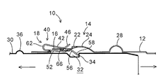
次に、図面に基づき本発明の実施の形態を詳述する。図1は本発明の一実施例を示す配管の抜け止め装置10を備えた配管(外管12内に内管30が挿入される状態を示す)の斜視図、図2は外管12に形成した突出部14へストッパ40を挿入する状態を示す外管12の斜視図、図3は本発明の配管の抜け止め装置10を構成するストッパ40の正面図をそれぞれ示している。
Next, embodiments of the present invention will be described in detail with reference to the drawings. FIG. 1 is a perspective view of a pipe (showing a state where the
本実施形態における配管の抜け止め装置10は、暖房用及び給湯用機器としてガスや化石燃料を用いた機器に接続される配管(内管30と外管12)が接続部で抜け落ちてしまうのを防止するためのもので、図1に示すように、突出部14を備えた外管12内に、凹陥部32を備えた内管30が挿入され、突出部14と凹陥部32とがストッパ40で係合されて抜け落ちないように構成している。
The
該配管の抜け止め装置10は、外管12と一体に突出形成されている突出部14と、内管30と一体に凹陥形成された凹陥部32と、外管12内に挿入された内管30が抜けないように、外管12に形成した突出部14と内管30に形成した凹陥部32とに係合されるストッパ40とから構成されている。該外管12は、図2に示すように一端近傍に突出部14を備えており、この突出部14は外管12の半径方向外側に突出形成され、凹陥部32は内管30の半径方向内側に凹陥形成されている。この外管12及び内管30は、板厚約0.3mmのステンレス製の金属板にて円筒形に形成されている。尚、ストッパ40については後に詳しく説明する。
The
該突出部14は、低突出部16と高突出部24とか構成されており、低突出部16は幅約10.2mm(外管12の円周方向寸法)、高さ約1.0mm(突出寸法)、長さ約10.2mm(外管12の長手方向寸法)に形成されており、この低突出部16の一端側(外管12の内管30が挿入される側)の側面が開口して挿入孔18が形成されている。高突出部24は低突出部16に連続して突出形成されると共に、この高突出部24は、外管12の一端側とは反対側に形成され、低突出部16より約2倍の高さに突出形成されている。尚、挿入孔18は、低突出部16同様の幅約10.2mm、高さは低突出部16と同様の約1.0mmに形成されている。
The
低突出部16の上面には、当該低突出部16の内外を貫通する係合孔20(本発明の突出部側係合部に相当)が形成されており、この係合孔20の高突出部24側に位置して低突出部16より高く突出する乗り上げ部22が形成されている。係合孔20は、低突出部16の一端側と他端側(外管12の一端側方向と他端側方向)との略中心から乗り上げ部22まで形成されると共に、乗り上げ部22は、高突出部24と同等高さに形成されている。また、係合孔20と乗り上げ部22は、幅約3mmに形成され、低突出部16の幅方向(外管12の円周方向)略中心に位置して形成されている。
An engaging hole 20 (corresponding to the protruding portion side engaging portion of the present invention) penetrating the inside and outside of the low protruding
また、高突出部24の低突出部16側には、傾斜壁26(図6に図示)が形成されており、この傾斜壁26は、乗り上げ部22の両側に形成されると共に、高突出部24の長手方向略中心から外管12の一端方向に行くに従って外管12の径中心方向に傾斜している。即ち、傾斜壁26は、高突出部24の最も突出している箇所から低突出部16間に形成されている。該高突出部24の低突出部16と反対側も、傾斜壁26同様低突出部16側から離間するに従って外管12の径中心方向に傾斜している。そして、この高突出部24は、当該高突出部24内にストッパ40の湾曲部56が位置して収まるように構成している。尚、28は、Oリング挿入突部で、このOリング挿入突部28に図示しないOリングが挿入され、このOリングによって外管12と内管30との隙間が閉塞される。
In addition, an inclined wall 26 (shown in FIG. 6) is formed on the low protruding
また、内管30には、当該内管30の半径方向内側に所定寸法陥没する凹陥部32が形成されており、この内管30の凹陥部32は当該内管30が外管12内に挿入される側の端部(内管30の他端)近傍の周囲全体に形成されている。この凹陥部32には、内管30の他端側に後述するストッパ40の係合部58が当接する係合壁34を備えている。詳しくは、凹陥部32の係合壁34は、内管30の他端近傍側に位置して当該内管30の長手方向に直交して形成されると共に、内管30の径中心方向に向かって形成されている。これにより、係合壁34に当接したストッパ40の係合部58が凹陥部32より離脱しないように構成されている。
Further, the
また、外管12内に内管30が挿入されて、当該外管12の突出部14(高突出部24)と内管30の凹陥部32とが対応した状態で、内管30の所定位置には、外管12の一端部が当接する位置決め突部36が半径方向外側に突出形成されている。即ち、外管12内に内管30が挿入されるとき、外管12の一端を内管30の位置決め突部36に当接させるだけで、外管12の高突出部24と内管30の凹陥部32とを対応させられるように構成している。これにより、外管12の高突出部24と内管30の凹陥部32との位置合わせが容易に行えるように構成している。
Further, the
一方、前記外管12の突出部14に対応してストッパ40(湾曲部56)が位置するように設けられており、このストッパ40は弾性を有し、熱に強く、錆び難い部材(例えば、板厚約0.4mmのステンレス、或いは、リン青銅などのバネ材)にて構成されている。即ち、ストッパ40が変形しないように内管30及び外管12よりも強度が強い金属板にて構成されている。該ストッパ40は、図3に示すように幅約10mmに形成されると共に、長さ約13.5mmの外辺42と、この外辺42の一端より連続して折り返された長さ約16.6mmの内辺52とから構成されている。該外辺42と内辺52は、ストッパ40の一端側に位置し、湾曲した屈曲部62の両側に連続して一体に形成されると共に、屈曲部62によって側面ヘアピン形状に形成されている。この場合、屈曲部62から延在し、前記突出部14の挿入孔18内に挿入される一方の辺を内辺52、他方の辺を外辺42と称す。
On the other hand, a stopper 40 (curved portion 56) is provided corresponding to the protruding
外辺42は、図4に示すように外辺本体44と、この外辺本体44の他端部に形成された傾斜部46と係合辺48(本発明の第2の係合部に相当)とを備えている。傾斜部46は、外辺本体44の先端側が内辺52から離間する方向に折れ曲がって傾斜した形状に形成されると共に、係合辺48は、傾斜部46に連続して係合孔20一端側(挿入孔18側)の低突出部16に係合可能に構成されている。尚、ストッパ40の屈曲部62側を一側、傾斜部46及び湾曲部56側を他側と称す。
As shown in FIG. 4, the
該係合辺48は、外辺本体44の幅方向略中央に位置して長さ約1.9mm、幅約2.5mmに形成されている。詳しくは、係合辺48は、外辺本体44の一部が打ち抜かれて、先端は内辺52側に延在すると共に、基部は傾斜部46と一体に接続されて前記傾斜部46と略一直線状態に形成されている。この傾斜部46と、前記高突出部24の低突出部16側に形成された傾斜壁26とは、Oリング挿入突部28方向に行くに従って拡開している(図9)。尚、Oリング挿入突部28方向に行くに従って傾斜部46と傾斜壁26とを拡開させている理由は後に詳しく説明する。
The
また、内辺52は、内辺本体54と、この内辺本体54の他端部に形成された湾曲部56と、内辺本体54に形成された透孔60(図5のみ図示)とを備えている(図4、図5)。湾曲部56は、内辺本体54の他端部が外辺42の傾斜部46方向に湾曲突出し、先端は傾斜部46から離間する方向に延在することにより形成されている。この湾曲部56の先端に係合部58(本発明の第1の係合部に相当)を形成している。尚、透孔60は、係合辺48の下端(外辺42側)を逃がすためのものである。
The
該係合部58は、内辺本体54よりも所定寸法下方に延在(この場合、内辺52を基準にして外辺42から離間方向に約1.8mm延在)している。内辺52と外辺42は平行、若しくは、ストッパ40の一端側(屈曲部62側)に対して他端側(傾斜部46及び傾斜部46側)が狭い形状(図4に点線で図示)に形成されている。そして、内辺52と外辺42の他端側が離間されると、当該内辺52と外辺42の他端側が近接する方向に弾性力が働くように構成されている。この係合部58は、前述した如き前記内管30に形成した凹陥部32内に係合されるものである。
The engaging
次に、本実施例における配管の抜け止め装置10を用いた配管(内管30と外管12)の接続と引き抜きを図1、図2、図6、図7を参照して説明する。先ず、ストッパ40を外管12に挿着する。この場合ストッパ40の取り付け方は、図2に矢印で示すように外管12の低突出部16一端側側面に形成した挿入孔18内に、係合部58を挿入し、つづいて湾曲部56、内辺本体54を挿入して、外管12の突出部14にストッパ40を挿着する(図1、図6)。この状態で、外辺42の係合辺48は、低突出部16を乗り越え、係合孔20内に挿入される。
Next, connection and extraction of piping (the
次に、図1に矢印で示すように、内管30の他端側を外管12の一端より、当該外管12内に挿入すると共に、内管30に設けた位置決め突部36に外管12の一端を当接させる。この状態で、前述した如き外管12に形成した突出部14と、内管30に形成した凹陥部32とが対応した状態となって、ストッパ40の係合部58が、内管30に形成した凹陥部32内に入り込み、外管12と内管30とが接続部(外管12の一端部と内管30の他端部)で接続される(図6)。これにより、外辺本体44の略全体が外管12に当接した状態となり、内辺52の湾曲部56が傾斜部46に接触した状態となる。即ち、ストッパ40は、外管12の板厚を挟むように弾性作用が働く(傾斜部46及び湾曲部56にて突出部14の乗り上げ部22と、傾斜壁26に弾性力が働く)ように構成されている(図7)。
Next, as shown by an arrow in FIG. 1, the other end of the
このとき、内管30には、当該内管30の周囲全体に凹陥部32を形成しており、内管30の全周囲のどの位置においても、外管12に形成した突出部14と、内管30周囲に形成した凹陥部32とを対応状態にさせることができる。これにより、内管30周囲の凹陥部32のどの位置にでも、ストッパ40の係合部58を入り込ませることができる。従って、内管30或いは外管12を回転させて、ストッパ40の係合部58を位置合わせする必要もなくなり、外管12と内管30との接続作業を極めて容易に行うことができるようになる。
At this time, the
そして、外管12と内管30とが接続部で接続された状態で、図8に矢印で示すように、外管12と内管30とが離間する方向に移動(外管12より内管30を引き抜く方向に当該内管30が移動)させると、ストッパ40の内辺52他端の係合部58は、内管30の凹陥部32(係合壁34)に当接する。この状態で、外管12に形成した突出部14と、内管30に形成した凹陥部32とは対応状態から左右にずれる(Oリング挿入突部28と凹陥部32とが離間する方向にずれる)。これにより、ストッパ40の内辺52他端の係合部58が、内管30の凹陥部32内に係合し、外辺42の係合辺48が係合孔20内に進入して、低突出部16の係合孔20縁に係合する。即ち、ストッパ40によって外管12と内管30との引き抜きが阻止される。
Then, in a state where the
次に、ストッパ40の係合により外管12と内管30の引き抜きが阻止された状態から、外管12から内管30の取り外し方を図9、図10を参照して説明する。先ず、図9に示すように、内管30の位置決め突部36に外管12の一端を当接させて、外管12に形成した突出部14と、内管30に形成した凹陥部32とを対応させる。この状態で、傾斜部46と湾曲部56にて突出部14の乗り上げ部22と、傾斜壁26に弾性力が働いているストッパ40をOリング挿入突部28方向に押して移動させる。尚、内管30に位置決め突部36を設けていない場合には、目視にて外管12に形成した突出部14と、内管30に形成した凹陥部32とを対応させれば良い。
Next, how to remove the
具体的には、ストッパ40をOリング挿入突部28方向に押して移動させて行くと、傾斜部46は乗り上げ部22に当接し、更にストッパ40をOリング挿入突部28方向に移動させて行くと、外管12(板厚)を挟むように弾性力が働いているストッパ40の傾斜部46は、乗り上げ部22に当接しながら、当該乗り上げ部22に乗り上げて行く。このとき、湾曲部56は、傾斜壁26の内面に当接(本発明の外管12一端側の壁の内面に当接に相当)しながらOリング挿入突部28方向(詳しくは、高突出部24の最も突出している方向)に移動して行く。
Specifically, when the
そして、ストッパ40の屈曲部62を外管12の一端に押し付けた状態では、図10に示すように、ストッパ40の傾斜部46は乗り上げ部22に乗り上げ、湾曲部56は、ストッパ40の弾性力で傾斜壁26の最も突出している部分(高突出部24)、若しくは、高突出部24近傍に位置する。これにより、傾斜部46は、凹陥部32から外管12側に離脱して、突出部14の高突出部24内に位置して収まる。
In the state where the
この状態で、外管12から内管30を離間させれば、ストッパ40の係合部58が内管30の凹陥部32(係合壁34)に引っ掛かることなく、引き抜くことができる。即ち、外管12内から内管30を引き抜く場合は、ストッパ40をOリング挿入突部28方向に移動して、当該ストッパ40の屈曲部62を外管12の一端に押し付けることにより、湾曲部56が高突出部24内に収納されるので、内管30の凹陥部32内からストッパ40の係合部58を容易に離脱させることができる。そして、この状態で、外管12内から内管30を離間させれば、係合部58が凹陥部32(係合壁34)に引っ掛かることなく、当該外管12内から内管30を容易に引き抜くことができる。
If the
次に、ストッパ40の係合により外管12と内管30の引き抜きが阻止された状態では、外管12から内管30の取り外し操作を行わない限り、外管12内から内管30を引き抜くことができないという説明を図11、図12を参照して説明する。先ず、外管12内から内管30が抜けてしまう例を説明しておく。それは、傾斜部46と、高突出部24の低突出部16側に形成された傾斜壁26が、Oリング挿入突部28方向に行くに従って拡開せずに平行の場合である。
Next, in a state where the
即ち、内辺本体54と外辺本体44が平行な状態(図7矢印A間とB間)で、ストッパ40の係合部58が内管30の凹陥部32内に入り込んでいる場合、ストッパ40の係合部58が外管12の突出部14内(高突出部24内)に位置した状態においては、ストッパ40全体は、湾曲部56側が高突出部24内に入り外管12の半径方向外側に傾く(図11)ものの、内辺52と外辺42は平行状態である。また、湾曲部56が傾斜壁26に当接している状態で、ストッパ40がOリング挿入突部28方向に移動した場合でも、ストッパ40の係合部58が内管30の凹陥部32より離脱しても内辺52と外辺42は平行状態のままとなる。この場合、ストッパ40の他側(Oリング挿入突部28方向)は拡開していないので、当該ストッパ40には低突出部16方向へ復帰させる弾性力が働かず、ストッパ40の係合部58が内管30の凹陥部32内から離脱したままとなって、外管12内から内管30が抜けてしまう。
That is, when the inner side
このように、傾斜壁26と傾斜部46とが平行な場合、ストッパ40の係合部58が内管30の凹陥部32内から離脱している状態で、ストッパ40が外管12(突出部14)に挿着されてしまった場合、ストッパ40には低突出部16方向へ復帰させる弾性力が働かずに、外管12から内管30が抜けてしまう不都合が発生してしまう。また、何らかの外力が加わり、ストッパ40が動いて、当該ストッパ40の係合部58が内管30の凹陥部32内から離脱した状態になった場合でも、ストッパ40には低突出部16方向へ復帰させる弾性力が働かず、係合部58は内管30の凹陥部32内に戻らないので、同様に外管12から内管30が抜けてしまう不都合が発生してしまう。
Thus, when the
そこで、本発明では、前述した如き傾斜部46と傾斜壁26は、リング挿入突部28側に行くに従って拡開するように構成している(図9)。この場合、図12に示すようにストッパ40がOリング挿入突部28方向に移動し、湾曲部56が高突出部24内に位置して、ストッパ40の係合部58が内管30の凹陥部32より離脱した場合は、ストッパ40の他側(傾斜部46と凹陥部32)は、乗り上げ部22と傾斜壁26とによって拡開し、湾曲部56を低突出部16方向へ復帰させる弾性力が働く。これにより、拡開しているストッパ40の湾曲部56は、傾斜壁26によって高突出部24側から低突出部16方向に移動する弾性力が働く。従って、ストッパ40の係合部58を、内管30の凹陥部32から離脱した状態より、内管30の凹陥部32内に復帰させる、若しくは、復帰し易くさせることができる。
Therefore, in the present invention, the
即ち、ストッパ40がOリング挿入突部28方向に移動して、傾斜部46が突出部14の乗り上げ部22に乗り上げた場合、ストッパ40は他側が拡開される(傾斜部46と湾曲部56とが離間する)ので、拡開したストッパ40は狭まる方向の弾性力が増大して、Oリング挿入突部28方向に移動する負荷が大きくなる。また、突出部14の乗り上げ部22に乗り上げたストッパ40の傾斜部46を、乗り上げ部22から降りる方向(外管12の一端側)にストッパ40を移動させた場合、当該ストッパ40の傾斜部46と湾曲部56は狭まるので、ストッパ40をOリング挿入突部28から離間させる方向へ負荷は小さくなる。
That is, when the
これにより、湾曲部56を常時低突出部16側に位置させておくことができるようになるので、ストッパ40の内辺52他端の係合部58が、内管30の凹陥部32から離脱してしまうといった不都合を未然に防止することができる。従って、ストッパ40の弾性力により、係合部58を常時内管30の凹陥部32内に位置させておくことができるので、外管12内に挿入した内管30が抜けてしまうなどといった不都合を確実に防止することができる。
As a result, the
他方、ストッパ40が変形して抜け止め装置の役割を果たさない場合、外管12から内管30を引き抜いた状態で、傾斜部46を手で持ち上げ、低突出部16に形成した係合孔20から係合辺48を離脱させ、そのままストッパ40を外管12の一端方向に移動させる。これにより、突出部14からストッパ40を外すことができる。後は、前述した如き外管12の低突出部16に形成した挿入孔18内に、変形せずに配管の抜け止めに不具合のない新たなストッパ40の係合部58から挿入し、つづいて湾曲部56も挿入して、外管12の突出部14に位置させれば、ストッパ40を突出部14に取り付けることができる。これにより、従来のように、溶接によりカバーを外す手間を省くことができ、極めて容易にストッパ40の着脱を行うことができる。
On the other hand, when the
このように、外管12と、該外管12の一端より当該外管12内に挿入される内管30と、外管12の一端近傍に構成され、当該外管12の半径方向外側に突出する突出部14と、内管30の外管12内に挿入される側の端部に形成され、該内管30の半径方向内側に陥没する凹陥部32と、突出部14に対応して外管12に取り付けられる弾性を有したストッパ40とを備え、突出部14は、低突出部16と、該低突出部16の外管12一端側の側面に形成された挿入孔18と、低突出部16の外管12一端側とは反対側に連続する高突出部24と、低突出部16に形成された係合孔20と、該係合孔20の高突出部24側に位置して低突出部16より高く突出する乗り上げ部22とを有し、ストッパ40は、外辺42と、該外辺42一端の屈曲部62にて連続して折り返された内辺52と、該内辺52の他端に構成された係合部58と、該係合部58よりも屈曲部62側に位置して形成された係合辺48とを有し、内辺52が突出部14の挿入孔18から当該突出部14内に進入し、外辺42と内辺52により突出部14を挟んだ状態で外管12に取り付けられ、外管12より内管30を引き抜く方向に当該内管30が移動した場合、ストッパ40の内辺52他端の係合部58が内管30の凹陥部32に係合し、且つ、係合辺48が突出部14の係合孔20に係合することで引き抜きが阻止されると共に、突出部14の高突出部24に内管30の凹陥部32が対応した状態で、外辺42の他端が突出部14の乗り上げ部22に乗り上げる方向にストッパ40が移動された場合、該ストッパ40の内辺52他端の係合部58は内管30の凹陥部32より離脱するので、外管12より内管30を引き抜く方向に当該内管30が移動した場合、ストッパ40の係合辺48が突出部14の係合孔20内に進入して係合するので、外管12から内管30が抜けてしまうのを確実に防止することができる。
In this manner, the
これにより、従来のロック部材のようにストッパ40が変形して配管の抜け止め装置10の役割を果たさない場合に、外管12から溶接したカバーを外し、再度ロック部材をスライドガイドと外管12との隙間に挿入した後、カバーを外管12に溶接固定するなどといった煩雑な手間も掛からない。従って、ストッパ40が変形した場合、傾斜部46を手で持ち上げて係合辺48を係合孔20から離脱させ、外管12の一端方向に移動させるだけでストッパ40を取り外して交換することができ、配管の抜け止め装置10の利便性を大幅に向上させることができる。
As a result, when the
また、ストッパ40は、外辺42の他端部に形成され、先端側が内辺52から離間する方向に傾斜した傾斜部46と、内辺52の他端部に形成され、外辺42側に湾曲して先端が係合部58となる湾曲部56とを有し、傾斜部46が突出部14の乗り上げ部22に乗り上げる方向にストッパ40が移動された場合、湾曲部56が高突出部24の外管12一端側の壁の内面に当接しながら当該高突出部24内側に進入し、係合部58が凹陥部32より離脱すると共に、高突出部24の外管12一端側の壁とストッパ40の傾斜部46は、当該傾斜部46の先端に向かう程、相互に離間するので、外辺42と内辺52とを近接させようとするストッパ40の弾性力により、ストッパ40は傾斜部46が乗り上げ部22から降下し、且つ、湾曲部56が高突出部24内側から外管12一端側に離脱する方向に自動的に移動することになる。これにより、ストッパ40を外管12に取り付けた状態で、当該ストッパ40の内辺52先端の係合部は確実に内管30の凹陥部32に係合可能となるので、外管12内に内管30を差し込むことで、ストッパ40は確実に抜け止め機能を奏するようになる。
The
特に、ストッパ40の傾斜部46は、当該傾斜部46の先端に向かう程、相互に離間するので、ストッパ40の湾曲部56が外管12の他端方向で止まってしまうのを防止し、外管12の一端方向に位置させておくことができると共に、係合部58を常時凹陥部32に係合させておくことが可能となる。従って、係合部58が内管30の凹陥部32に係合しない、或いは、係合部58が内管30の凹陥部32から離脱してしまうのを未然に防止することができるので、外管12内に挿入した内管30が抜けてしまうなどといった不都合を確実に防止することができる。
In particular, since the
また、ストッパ40の屈曲部62は湾曲していると共に、外管12の挿入孔18下縁には、当該外管12の半径方向外側に突出する断面円弧状の案内部が形成され、外辺42の他端が突出部14の乗り上げ部22に乗り上げる方向にストッパ40が移動された場合、当該ストッパ40の屈曲部62が案内部の外管12一端側とは反対側の湾曲面に対応するので、この湾曲面と屈曲部62の湾曲形状を利用して、ストッパ40の外辺42の他端を突出部14の乗り上げ部22に乗り上げる方向に移動させれば、そのままストッパ40の屈曲部62を内管30側に円滑に押し込むことができる。これにより、内辺52の他端に構成された係合部58は、より内管30から離間する方向に移動することになるので、より確実且つ容易に係合部58を凹陥部32から高突出部24内に離脱させることができる。
Further, the
また、突出部14は、外管12と一体に突出形成されていると共に、凹陥部32は内管30の全周に渡って連続して形成されているので、ストッパ40が内管30周囲のどの位置においても内管30と外管12との抜け止め機能を奏することが可能となる。従って、配管の抜け止め装置10の利便性を極めて向上させることができる。
Further, since the protruding
次に、図13、図14には本発明の他の実施例の配管の抜け止め装置10を示している。該配管の抜け止め装置10は、前述の実施形態と略同じ構成を有している。以下、異なる部分について説明する。尚、前述の実施の形態と同じ部分にはこれと同じ符号を付し、説明を省略する。ここで、前記実施例1の構造では、ストッパ40の屈曲部62を外管12の一端に押し付けることにより、当該ストッパ40の湾曲部56を高突出部24内に収めて係合部58を内管30の凹陥部32より脱出させていたが、外管12は金属板にて円筒形に形成されているため、外管12の外側からはストッパ40の係合部58を視認できない。
Next, FIGS. 13 and 14 show a
そのため、屈曲部62を外管12の一端に押し付けただけでは、湾曲部56が高突出部24内に収まり、内管30の凹陥部32内より内辺52の係合部58が離脱しているか否か分かり難かった。そこで、実施例2の配管の抜け止め装置10は、図13、図14に示すように、外管12の挿入孔18下縁側に、当該外管12の半径方向外側に突出する断面円弧状の案内部27を形成している。この案内部27は、半径約0.8R、高さ約0.5mm、幅約5.0mmに形成されると共に、挿入孔18の幅方向略中心に位置して形成されている。
Therefore, if the
また、図15、図16に示すように、案内部27の挿入孔18側には、ストッパ40の屈曲部62と対応して接触させるための湾曲面27Aを備えている。該ストッパ40の屈曲部62は、案内部27の外管12一端側とは反対側の湾曲面27Aに対応させている。係るストッパ40の屈曲部62を、案内部27の湾曲面27Aに対応させているので、外辺42の他端(傾斜壁26)を突出部14の乗り上げ部22に乗り上げる方向にストッパ40を移動させれば、湾曲面27Aと屈曲部62の湾曲形状により、そのままストッパ40の屈曲部62を円滑に内管30側に押し込むことができる。
As shown in FIGS. 15 and 16, the
即ち、ストッパ40の湾曲部56を高突出部24内に納めるには、外辺42の傾斜壁26を突出部14の乗り上げ部22に乗り上げる方向にストッパ40を移動させれば、図17の矢印で示すように、湾曲面27Aにストッパ40の屈曲部62を滑らせれば、ストッパ40の屈曲部62を図18点線で示す位置から実線で示すように内管30側に押し込むことができる。
That is, in order to fit the
そして、ストッパ40による外管12と内管30との引き抜きの阻止は、外管12と内管30とが接続部で接続された状態(図17の湾曲面27Aにストッパ40の屈曲部62を滑らせ以前の状態)から、図19に矢印で示すように、外管12と内管30とが離間する方向に移動(外管12より内管30を引き抜く方向に当該内管30が移動)させると、ストッパ40の内辺52他端の係合部58は、内管30の凹陥部32(係合壁34)に当接する。この状態で、外管12に形成した突出部14と、内管30に形成した凹陥部32とは対応状態から左右にずれる(Oリング挿入突部28と凹陥部32とが離間する方向にずれる)。
The
これにより、ストッパ40の内辺52他端の係合部58が、内管30の凹陥部32内に係合し、外辺42の係合辺48が係合孔20内に進入して、低突出部16の係合孔20縁に係合する。即ち、挿入孔18下縁に案内部27を形成した外管12であっても前述した実施例同様、ストッパ40によって外管12と内管30との引き抜きを阻止することができる。
As a result, the engaging
これにより、ストッパ40の内辺52他端に形成した係合部58を、より内管30から離間する方向に移動させることができるので、当該係合部58を凹陥部32からより確実且つ容易に高突出部24内に離脱させることができる。即ち、ストッパ40の屈曲部62を、湾曲面27Aから内管30側に押し込むだけで、湾曲部56を高突出部24内に収めることができるので、外管12の外側からストッパ40の係合部58が視認できなくても、内管30の凹陥部32内より内辺52の係合部58が離脱したのを確実に把握することができる。
Thereby, the engaging
また、実施例1のような構造においても、ストッパ40の湾曲部56を容易且つ確実に高突出部14内に進入させることができるので、ストッパ40の内辺52他端に形成した係合部58を凹陥部32から確実に高突出部24内に離脱させることができる。尚、湾曲面27Aは、ストッパ40の屈曲部62を内管30側に円滑に押し込むことができれば、湾曲面27Aの一番高い箇所から挿入孔18下縁まで傾斜面としても差し支えない。
Also in the structure as in the first embodiment, the
このように、ストッパ40は、外辺42と内辺52の一端側に位置する湾曲した屈曲部62にて連続すると共に、外管12の挿入孔18下縁には、当該外管12の半径方向外側に突出する断面円弧状の案内部27が形成され、外辺42の他端が突出部14の乗り上げ部22に乗り上げる方向にストッパ40が移動した場合、当該ストッパ40の屈曲部62が案内部27の外管12一端側とは反対側の湾曲面27Aに対応するので、この湾曲面27Aと屈曲部62の湾曲形状を利用して、ストッパ40の外辺42の他端を突出部14の乗り上げ部22に乗り上げる方向に移動させれば、ストッパ40の屈曲部62は円滑に湾曲面27Aを内管30方向に滑り落ちて、そのまま屈曲部62を内管30側に押し込むことができる。これにより、ストッパ40の内辺52他端の係合部58は、より内管30から離間する方向に移動することになるので、より確実且つ容易に係合部58を凹陥部32から高突出部24内に離脱させることができる。
Thus, the
他方、前述したように低突出部16の一端側に開口した挿入孔18を設けているので、挿入孔18部分の外管12の強度が弱くなるが、本実施の形態では、外管12の挿入孔18下縁側に、当該外管12の半径方向外側に突出する断面円弧状の案内部27を形成しているので、外管12の挿入孔18部分の強度を向上させることができる。これにより、ストッパ40の屈曲部62を、湾曲面27Aを滑らせて内管30方向に移動させる際、外管12が凹んでしまうなどと言った不都合を防止することができる。従って、外管12の凹みによりストッパ40の角度が変わり、ストッパ40の係合部58が内管30の凹陥部32(係合壁34)から脱出して、配管の抜け止め機能を果たさなくなってしまうなどと言った不都合を未然に阻止することができる。
On the other hand, since the
次に、図20、図21、図22には本発明の他の実施例の配管の抜け止め装置10を示している。該配管の抜け止め装置10は、前述の実施形態と略同じ構成を有している。以下、異なる部分について説明する。尚、前述の実施の形態と同じ部分にはこれと同じ符号を付し、説明を省略する。該配管の抜け止め装置10は、前記実施例に対して外管12に一体に突出成形されている突出部14と、ストッパ40の一部を変更して、外管12より内管30を引き抜く方向の、ストッパ40の強度を大幅に向上している。
Next, FIGS. 20, 21, and 22 show a
即ち、突出部14は、図20、図21に示すように、前実施例の係合孔20の代わりに係合凹部64(本発明の突出部側係合部に相当)を設けている。この係合凹部64は、後述するストッパ40の乗り上げ突部66を逃がすためのもので、突出部14を構成する低突出部16の一部を外管12の径中心方向に凹陥することにより形成している。該係合凹部64は、図22に示すように低突出部16の一端側に開口した挿入孔18より少許離間した位置から高突出部24の所定寸法手前まで凹陥形成され、高突出部24側を開口している。そして、この開口下縁(外管12の径中心側)に、後述するストッパ40の透孔61が係合する係合端部65を構成している。
That is, as shown in FIGS. 20 and 21, the protruding
また、ストッパ40は図23、図24に示すように、前実施例の外辺42の係合辺48の代わりに、乗り上げ突部66(本発明の突部に相当)を設けている。該乗り上げ突部66は、内辺52側に半球形に凹陥形成されると共に、この乗り上げ突部66の周縁は略外辺42に接して設けられている。詳しくは、乗り上げ突部66は、前実施例の係合辺48と傾斜部46同様に、傾斜部46から半球形状の乗り上げ突部66の頂点まで傾斜状態が延長されるように形成されている。この場合、乗り上げ突部66を半球形状に形成することにより、前実施例の係合辺48部分の強度を大幅に向上している。
Further, as shown in FIGS. 23 and 24, the
そして、ストッパ40は通常状態では、点線状態(外辺42と内辺52とが近接した状態)にあり、外辺42と内辺52とを離間させた状態(図中実線)では、所定の付勢力で、内辺52と外辺42とが近接するように弾性力が働くように構成されている。尚、ストッパ40の通常状態で、ストッパ40の乗り上げ突部66は係合凹部64内に突出している。また、乗り上げ突部66は、前実施例の係合辺48であっても差し支えない。この場合、係合辺48に図示しない補強リブを設るなどして、係合辺48が変形しないようにする必要がある。
The
また、ストッパ40の内辺52には、当該内辺52を貫通して透孔61(本発明の第2の係合部に相当)が設けられている。この透孔61は、縦長略矩形状(長さ約7.3mm、幅約4.0mm)に形成されており、一方の縁61Aを湾曲部56の略中心に位置して、そこから延在して他方の縁61Bを屈曲部62近傍に位置すると共に、ストッパ40の幅方向略中心に位置して形成されている。
Further, the
また、ストッパ40の内辺52には補強リブ68が設けられている。該補強リブ68は、図25に示すように湾曲部56の変形を防止するためのもので、湾曲部56の屈曲部62側から係合部58方向に渡って形成されている。この補強リブ68は、湾曲部56が外辺42と反対側面方向に凹陥されることにより設けられると共に、補強リブ68は透孔61両側にそれぞれ設けられている。即ち、ストッパ40の係合部58が透孔61方向に押圧された場合に湾曲部56が屈曲しないように、透孔61両側に補強リブ68が設けられている。尚、補強リブ68は、図24、図25のみ図示している。
A reinforcing
次に、本実施例における配管の抜け止め装置10を用いた配管(内管30と外管12)の接続を図26、図27、図28を参照して説明する。先ず、ストッパ40を外管12に挿着する。この場合ストッパ40の取り付け方は、図26に矢印で示すように外管12の低突出部16一端側側面に形成した挿入孔18内に、係合部58を挿入し、つづいて湾曲部56、内辺本体54を挿入して、外管12の突出部14にストッパ40を挿着する。この状態で、外辺42の乗り上げ突部66は、低突出部16を乗り越え、係合凹部64内に挿入される。
Next, connection of pipes (
次に、図27に矢印で示すように、内管30の他端側を外管12の一端より、当該外管12内に挿入すると共に、内管30に設けた位置決め突部36に外管12の一端を当接させる。この状態で、図28に示すように外管12に形成した突出部14と、内管30に形成した凹陥部32とが対応した状態となって、ストッパ40の係合部58が、内管30に形成した凹陥部32内に入り込み、外管12と内管30とが接続部(外管12の一端部と内管30の他端部)で接続される。
Next, as indicated by an arrow in FIG. 27, the other end of the
係る内管30には、当該内管30の周囲全体に凹陥部32を形成しており、内管30の全周囲のどの位置においても、外管12に形成した突出部14と、内管30周囲に形成した凹陥部32とを対応状態にさせることができる。これにより、内管30周囲の凹陥部32のどの位置にでも、ストッパ40の係合部58を入り込ませることができる。従って、内管30或いは外管12を回転させて、ストッパ40の係合部58を位置合わせする必要もなくなり、外管12と内管30との接続作業を極めて容易に行うことができるようになる。
In the
また、外管12と内管30とが接続部で接続された状態では、内辺52に設けた透孔61内に突出部14の低突出部16に設けた係合凹部64が挿入された状態となる。この状態から、ストッパ40をOリング挿入突部28側に移動させると、乗り上げ突部66は突出部14の乗り上げ部22に乗り上げ、内辺52と外辺42とが離間する。即ち、内辺52と外辺42が離間すると、ストッパ40は付勢力で内辺52と外辺42とを近接させる。これにより、ストッパ40(乗り上げ突部66)が乗り上げ部22に乗り上げないように構成されている。
In addition, in a state where the
そして、外管12と内管30とが接続部で接続された状態で、図29に矢印で示すように、外管12と内管30とが離間する方向に移動(外管12より内管30を引き抜く方向に当該内管30が移動)させると、ストッパ40の内辺52他端の係合部58は、内管30の凹陥部32(係合壁34)に当接する。この状態で、外管12に形成した突出部14と、内管30に形成した凹陥部32とは対応状態から左右にずれる(Oリング挿入突部28と凹陥部32とが離間する方向にずれる)。
Then, in a state where the
この場合、ストッパ40の内辺52他端の係合部58が、内管30の凹陥部32内に係合し、外管12突出部14の係合凹部64(係合端部65)が内辺52の透孔61内に進入する。詳しくは、外管12と内管30が離間する方向に移動すると、内管30(凹陥部32の係合壁34)は、湾曲部56先端の係合部58を、ストッパ40の屈曲部62方向に押し、外管12(係合凹部64の係合端部65)は、透孔61の一方の縁61Aを係合部58方向に押す。これにより、内管30と外辺42は、ストッパ40の湾曲部56部分で突っ張り、引き抜きが阻止されることとなる。この場合、ストッパ40には、湾曲部56に補強リブ68を設けているので、湾曲部56のへたりや、屈曲を防止して、湾曲部56の変形による内管30と外辺42との引き抜きを確実に阻止することができる。
In this case, the engaging
尚、係合端部65を高突出部24側に鋭角に形成すると共に、内管30凹陥部32の係合壁34下端(内管30の径中心側)を位置決め突部36よりも離間する方向に傾斜させても差し支えない。この場合、外管12と内管30とがストッパ40により引き抜きが阻止された状態で、外管12と内管30とを引き抜く方向に移動した場合、透孔61の一方の縁61Aは、係合端部65の乗り上げ部22側に付勢され、湾曲部56先端の係合部58は、係合壁34下端(内管30の径中心側)方向に付勢されることになるので、係合端部65とストッパ40の透孔61(一方の縁61A)、内管30凹陥部32の係合壁34下端とストッパ40の係合部58を外れ難くすることができる。
The
次に、ストッパ40の係合により外管12と内管30の引き抜きが阻止された状態から、外管12から内管30の取り外し方を、図30を参照して説明する。先ず、図30に示すように、内管30の位置決め突部36に外管12の一端を当接させて、外管12に形成した突出部14と、内管30に形成した凹陥部32とを対応させる。この状態で、内辺52と外辺42とが相互に近接方向に弾性力が働いているストッパ40をOリング挿入突部28方向に押して移動させる。尚、内管30に位置決め突部36を設けていない場合には、目視にて外管12に形成した突出部14と、内管30に形成した凹陥部32とを対応させれば良い。
Next, how to remove the
具体的には、ストッパ40をOリング挿入突部28方向に押して移動させて行くと、乗り上げ突部66は乗り上げ部22に当接し、更にストッパ40をOリング挿入突部28方向に移動させて行くと、外管12(板厚)を挟むように弾性力が働いているストッパ40の乗り上げ突部66は、乗り上げ部22に当接しながら、当該乗り上げ部22に乗り上げて行く。このとき、湾曲部56は、傾斜壁26の内面に当接(本発明の外管12一端側の壁の内面に当接に相当)しながらOリング挿入突部28方向(詳しくは、高突出部24の最も突出している方向)に移動して行く。
Specifically, when the
そして、ストッパ40の屈曲部62を外管12の一端に押し付けた状態では、ストッパ40の乗り上げ突部66は乗り上げ部22に乗り上げ、湾曲部56は、ストッパ40の弾性力で傾斜壁26の最も突出している部分(高突出部24)、若しくは、高突出部24近傍に位置する。これにより、傾斜部46は、凹陥部32から外管12側に離脱して、突出部14の高突出部24内に位置して収まる。即ち、前述した如きストッパ40の屈曲部62を、湾曲面27Aから内管30側に押し込むことにより、湾曲部56を高突出部24内に収めることができるので、外管12の外側からストッパ40の係合部58が視認できなくても、内管30の凹陥部32内より内辺52の係合部58が離脱したのを確実に把握することができる。
When the
この状態で、外管12から内管30を離間させれば、ストッパ40の係合部58が内管30の凹陥部32(係合壁34)に引っ掛かることなく、引き抜くことができる。即ち、外管12内から内管30を引き抜く場合は、ストッパ40をOリング挿入突部28方向に移動して、当該ストッパ40の屈曲部62を外管12の一端に押し付けることにより、湾曲部56が高突出部24内に収納されるので、内管30の凹陥部32内からストッパ40の係合部58を容易に離脱させることができる。そして、この状態で、外管12内から内管30を離間させれば、係合部58が凹陥部32(係合壁34)に引っ掛かることなく、当該外管12内から内管30を容易に引き抜くことができる。
If the
このように、外管12より内管30を引き抜く方向に当該内管30が移動した場合、突出部14の係合凹部64をストッパ40の透孔61内に進入させて係合させることができるので、係合凹部64と透孔61間のストッパ40寸法を全実施例の外辺42の係合辺48から屈曲部62を介して内辺52端部の係合部58までの寸法に対して極めて短寸法にすることができる。これにより、外管12より内管30を引き抜く方向の、ストッパ40の強度を大幅に向上させることができる。従って、ストッパ40が変形して、外管12内に挿入した内管30が抜けてしまうなどといった不都合を確実に防止することが可能となる。
As described above, when the
また、ストッパ40は、先端側が内辺52から離間する方向に傾斜した傾斜部46と、該傾斜部46の屈曲部62側の外辺42に形成されて、内辺52側に突出する乗り上げ突部66とを有するので、乗り上げ突部66が突出部14の乗り上げ部22に乗り上げる方向にストッパ40が移動された場合、ストッパ40の内辺52と外辺42との離間距離を大きくすることが可能となる。これにより、離間した内辺52と外辺42とが狭まる付勢力を更に大きくすることができる。この場合、ストッパ40の湾曲部56が外管12の他端方向で停止してしまうのを未然に阻止して、外管12の一端方向に確実に位置させておくことができるので、係合部58が内管30の凹陥部32に係合しない、或いは、係合部58が内管30の凹陥部32から離脱してしまうのを未然に防止することができる。これにより、外管12内に挿入した内管30が抜けてしまうなどといった不都合を確実に防止することができる。
Further, the
また、ストッパ40は、内辺52の他端部に形成され、外辺42側に湾曲して先端が係合部58となる湾曲部56を有し、ストッパ40の透孔61は湾曲部56の屈曲部62側の面まで延在している。そして、透孔61両側に位置する湾曲部56の外辺42とは反対側の面には、補強リブ68が外辺42とは反対方向に凹陥形成されているので、湾曲部56の変形応力を大幅に向上させることができる。これにより、内管30と外管12とに引き抜き方向の力が加わった場合に、ストッパ40の湾曲部56が変形してしまうなどと言った不都合を防止することができる。従って、外管12内に挿入した内管30が抜けてしまうのを確実に防止することができる。また、これ以外に前記実施例1、実施例2同様の効果を得ることができる。
The
尚、実施の形態では、配管の抜け止め装置10の形状や寸法或いは角度などを記載したが、配管の抜け止め装置10の要旨を逸脱しない範囲内で形状や寸法或いは角度などを変更しても良いのは言うまでもない。勿論本発明は、上記実施例のみに限定されるものではなく、この発明の趣旨を逸脱しない範囲で他の様々な変更を行っても本発明は有効である。
In the embodiment, the shape, size, or angle of the
10 配管の抜け止め装置
12 外管
14 突出部
16 低突出部
18 挿入孔
20 係合孔(突出部側係合部)
22 乗り上げ部
24 高突出部
26 傾斜壁
27 案内部
27A 湾曲面
28 Oリング挿入突部
30 内管
32 凹陥部
34 係合壁
36 位置決め突部
40 ストッパ
42 外辺
44 外辺本体
46 傾斜部
48 係合辺(第2の係合部)
52 内辺
54 内辺本体
56 湾曲部
58 係合部(第1の係合部)
60 透孔(第2の係合部)
61 透孔(第2の係合部)
61A 一方の縁
61B 他方の縁
62 屈曲部
64 係合凹部(突出部側係合部)
65 係合端部
66 乗り上げ突部
68 補強リブ
DESCRIPTION OF
DESCRIPTION OF
52
60 Through hole (second engaging portion)
61 Through hole (second engaging portion)
61A One
65
Claims (8)
前記突出部は、低突出部と、該低突出部の前記外管一端側の側面に形成された挿入孔と、前記低突出部の前記外管一端側とは反対側に連続する高突出部と、前記低突出部に形成された突出部側係合部と、該突出部側係合部の前記高突出部側に位置して前記低突出部より高く突出する乗り上げ部とを有し、
前記ストッパは、外辺と、該外辺一端の屈曲部にて連続して折り返された内辺と、該内辺の他端に構成された第1の係合部と、該第1の係合部よりも前記屈曲部側に位置して形成された第2の係合部とを有し、前記内辺が前記突出部の挿入孔から当該突出部内に進入し、前記外辺と内辺により前記突出部を挟んだ状態で前記外管に取り付けられ、
前記外管より前記内管を引き抜く方向に当該内管が移動した場合、前記ストッパの内辺他端の第1の係合部が前記内管の凹陥部に係合し、且つ、前記第2の係合部が前記突出部の突出部側係合部に係合することで引き抜きが阻止されると共に、
前記突出部の高突出部に前記内管の凹陥部が対応した状態で、前記外辺の他端が前記突出部の乗り上げ部に乗り上げる方向に前記ストッパが移動された場合、該ストッパの内辺他端の第1の係合部は前記内管の凹陥部より離脱することを特徴とする配管の抜け止め装置。 An outer tube, an inner tube that is inserted into the outer tube from one end of the outer tube, a protrusion that is configured near one end of the outer tube and protrudes radially outward of the outer tube, and the inner tube A recessed portion formed at an end portion on the side to be inserted into the outer tube and recessed inward in the radial direction of the inner tube; and a stopper having elasticity attached to the outer tube corresponding to the protruding portion;
The protruding portion includes a low protruding portion, an insertion hole formed in a side surface of the low protruding portion on one end side of the outer tube, and a high protruding portion continuous on the side of the low protruding portion opposite to the one end side of the outer tube. And a projecting portion side engaging portion formed in the low projecting portion, and a riding portion that is located on the high projecting portion side of the projecting portion side engaging portion and projects higher than the low projecting portion,
The stopper includes an outer side, an inner side continuously folded at a bent portion at one end of the outer side, a first engaging portion configured at the other end of the inner side, and the first engagement. A second engaging portion formed on the bent portion side with respect to the joint portion, and the inner side enters the protruding portion from the insertion hole of the protruding portion, and the outer side and the inner side Is attached to the outer tube with the protruding portion sandwiched therebetween,
When the inner tube moves in a direction in which the inner tube is pulled out from the outer tube, the first engaging portion at the other end of the inner side of the stopper engages with the recessed portion of the inner tube, and the second The engagement portion is engaged with the projecting portion side engaging portion of the projecting portion, so that the withdrawal is prevented,
When the stopper is moved in a direction in which the other end of the outer side rides on the riding part of the projecting part in a state where the recessed part of the inner tube corresponds to the high projecting part of the projecting part, the inner side of the stopper The piping retaining device, wherein the first engaging portion at the other end is separated from the recessed portion of the inner tube.
前記ストッパの第2の係合部は、前記外辺より内辺側に突出する係合辺であって、
前記外管より前記内管を引き抜く方向に当該内管が移動した場合、前記ストッパの係合辺が前記突出部の係合孔内に進入して係合することを特徴とする請求項1に記載の配管の抜け止め装置。 The protrusion-side engagement portion of the protrusion is an engagement hole formed on the upper surface of the low protrusion,
The second engaging portion of the stopper is an engaging side that protrudes inward from the outer side,
The engagement side of the stopper enters the engagement hole of the projecting portion and engages when the inner tube moves in a direction in which the inner tube is pulled out from the outer tube. Detaching device for piping as described.
前記傾斜部が前記突出部の乗り上げ部に乗り上げる方向に前記ストッパが移動された場合、前記湾曲部が前記高突出部の前記外管一端側の壁の内面に当接しながら当該高突出部内側に進入し、前記第1の係合部が前記凹陥部より離脱すると共に、
前記高突出部の前記外管一端側の壁と前記ストッパの傾斜部は、当該傾斜部の先端に向かう程、相互に離間することを特徴とする請求項2に記載の配管の抜け止め装置。 The stopper is formed at the other end of the outer side, the tip side is inclined in a direction away from the inner side, and is formed at the other end of the inner side, and is curved toward the outer side. A distal end has a curved portion serving as the first engaging portion;
When the stopper is moved in a direction in which the inclined portion rides on the riding portion of the projecting portion, the curved portion comes into contact with the inner surface of the wall on the one end side of the outer tube of the high projecting portion. Entering, the first engaging portion is disengaged from the recessed portion,
3. The piping retaining device according to claim 2, wherein the wall on the one end side of the outer pipe of the high protruding portion and the inclined portion of the stopper are separated from each other toward the tip of the inclined portion.
前記ストッパの第2の係合部は、前記内辺に形成された透孔であって、
前記外管より前記内管を引き抜く方向に当該内管が移動した場合、前記突出部の係合凹部が前記ストッパの透孔内に進入して係合することを特徴とする請求項1に記載の配管の抜け止め装置。 The protruding portion side engaging portion of the protruding portion is an engaging recess formed as a recess in the low protruding portion,
The second engaging portion of the stopper is a through hole formed in the inner side,
2. The engagement recess of the protrusion enters the through hole of the stopper and engages when the inner tube moves in a direction in which the inner tube is pulled out from the outer tube. Piping prevention device.
Priority Applications (1)
| Application Number | Priority Date | Filing Date | Title |
|---|---|---|---|
| JP2008149291A JP5108638B2 (en) | 2008-06-06 | 2008-06-06 | Piping prevention device |
Applications Claiming Priority (1)
| Application Number | Priority Date | Filing Date | Title |
|---|---|---|---|
| JP2008149291A JP5108638B2 (en) | 2008-06-06 | 2008-06-06 | Piping prevention device |
Publications (2)
| Publication Number | Publication Date |
|---|---|
| JP2009293732A JP2009293732A (en) | 2009-12-17 |
| JP5108638B2 true JP5108638B2 (en) | 2012-12-26 |
Family
ID=41542081
Family Applications (1)
| Application Number | Title | Priority Date | Filing Date |
|---|---|---|---|
| JP2008149291A Active JP5108638B2 (en) | 2008-06-06 | 2008-06-06 | Piping prevention device |
Country Status (1)
| Country | Link |
|---|---|
| JP (1) | JP5108638B2 (en) |
Families Citing this family (2)
| Publication number | Priority date | Publication date | Assignee | Title |
|---|---|---|---|---|
| KR101729160B1 (en) * | 2015-07-16 | 2017-04-21 | 김경석 | Connection structure of duct |
| CN114498090B (en) * | 2021-12-21 | 2024-06-07 | 平高集团有限公司 | Conductive component and connection structure between conductive pieces |
Family Cites Families (13)
| Publication number | Priority date | Publication date | Assignee | Title |
|---|---|---|---|---|
| JPS62107189U (en) * | 1985-12-25 | 1987-07-08 | ||
| JPS6368591U (en) * | 1986-10-23 | 1988-05-09 | ||
| JPH01255790A (en) * | 1988-04-06 | 1989-10-12 | Toosetsu Kk | Joining construction for new charge and exhaust cylinder |
| JP2519381Y2 (en) * | 1990-09-27 | 1996-12-04 | 日本プラスト株式会社 | Air-conditioning duct connection structure |
| JP2648114B2 (en) * | 1995-01-17 | 1997-08-27 | トーセツ株式会社 | Connecting structure of supply and exhaust cylinders |
| JPH0953779A (en) * | 1995-08-16 | 1997-02-25 | Kiyousan Denki Kk | One touch connecting structure using block joint |
| JPH09264527A (en) * | 1996-03-27 | 1997-10-07 | Hokuai:Kk | Air supplying or air discharging pipe for gas equipment |
| JP3108030B2 (en) * | 1997-03-13 | 2000-11-13 | 東京フォーミング株式会社 | Pipe retaining device |
| JP3326398B2 (en) * | 1998-11-20 | 2002-09-24 | トーセツ株式会社 | Supply / exhaust pipe retaining device |
| JP3288025B2 (en) * | 1999-04-19 | 2002-06-04 | トーセツ株式会社 | Supply / exhaust pipe retaining device |
| JP2005030467A (en) * | 2003-07-10 | 2005-02-03 | Yamato Stainless:Kk | Fall-out stopper and fall-out stopping method for air supply and exhaust pipe |
| JP2006009856A (en) * | 2004-06-23 | 2006-01-12 | Nippon Pipe System Kk | Slipping-off prevention device for supply/exhaust pipe |
| JP4758094B2 (en) * | 2004-11-26 | 2011-08-24 | トーセツ株式会社 | Air supply / exhaust pipe |
-
2008
- 2008-06-06 JP JP2008149291A patent/JP5108638B2/en active Active
Also Published As
| Publication number | Publication date |
|---|---|
| JP2009293732A (en) | 2009-12-17 |
Similar Documents
| Publication | Publication Date | Title |
|---|---|---|
| JP5715700B2 (en) | connector | |
| US7566077B2 (en) | Quick-connect coupling | |
| JP5939541B2 (en) | connector | |
| EP2871398B1 (en) | Connector | |
| EP2213924A1 (en) | Pipe fitting | |
| JP4744640B1 (en) | Tightening band | |
| JP2007255668A (en) | Quick connector | |
| US7347224B2 (en) | Supply and exhaust pipe | |
| JP5108638B2 (en) | Piping prevention device | |
| US7494161B2 (en) | Coming off preventing device of a joint of an air supply and exhaust pipe | |
| JP4330415B2 (en) | Pipe fitting | |
| JP2009293661A (en) | Plug | |
| US20080309079A1 (en) | Release Clip | |
| JP3677681B2 (en) | connector | |
| JP5941772B2 (en) | connector | |
| JP2007178003A (en) | Quick connector | |
| JP2004263791A (en) | Clip | |
| JP6027415B2 (en) | connector | |
| JP5787441B2 (en) | Piping connector | |
| JP2005121101A (en) | Clamp for connecting piping | |
| JP3698290B2 (en) | connector | |
| JP2000104878A (en) | Connector for connecting piping | |
| JP3086710U (en) | Gas injection tube connector | |
| JP2006009856A (en) | Slipping-off prevention device for supply/exhaust pipe | |
| JP6368556B2 (en) | Hose clamp |
Legal Events
| Date | Code | Title | Description |
|---|---|---|---|
| A621 | Written request for application examination |
Free format text: JAPANESE INTERMEDIATE CODE: A621 Effective date: 20110407 |
|
| A977 | Report on retrieval |
Free format text: JAPANESE INTERMEDIATE CODE: A971007 Effective date: 20120911 |
|
| TRDD | Decision of grant or rejection written | ||
| A01 | Written decision to grant a patent or to grant a registration (utility model) |
Free format text: JAPANESE INTERMEDIATE CODE: A01 Effective date: 20120925 |
|
| A01 | Written decision to grant a patent or to grant a registration (utility model) |
Free format text: JAPANESE INTERMEDIATE CODE: A01 |
|
| A61 | First payment of annual fees (during grant procedure) |
Free format text: JAPANESE INTERMEDIATE CODE: A61 Effective date: 20121005 |
|
| R150 | Certificate of patent or registration of utility model |
Ref document number: 5108638 Country of ref document: JP Free format text: JAPANESE INTERMEDIATE CODE: R150 Free format text: JAPANESE INTERMEDIATE CODE: R150 |
|
| FPAY | Renewal fee payment (event date is renewal date of database) |
Free format text: PAYMENT UNTIL: 20151012 Year of fee payment: 3 |
|
| S533 | Written request for registration of change of name |
Free format text: JAPANESE INTERMEDIATE CODE: R313533 |
|
| R350 | Written notification of registration of transfer |
Free format text: JAPANESE INTERMEDIATE CODE: R350 |
|
| R250 | Receipt of annual fees |
Free format text: JAPANESE INTERMEDIATE CODE: R250 |
|
| R250 | Receipt of annual fees |
Free format text: JAPANESE INTERMEDIATE CODE: R250 |
|
| R250 | Receipt of annual fees |
Free format text: JAPANESE INTERMEDIATE CODE: R250 |
|
| S531 | Written request for registration of change of domicile |
Free format text: JAPANESE INTERMEDIATE CODE: R313531 |
|
| S533 | Written request for registration of change of name |
Free format text: JAPANESE INTERMEDIATE CODE: R313533 |
|
| R350 | Written notification of registration of transfer |
Free format text: JAPANESE INTERMEDIATE CODE: R350 |
|
| R250 | Receipt of annual fees |
Free format text: JAPANESE INTERMEDIATE CODE: R250 |
|
| R250 | Receipt of annual fees |
Free format text: JAPANESE INTERMEDIATE CODE: R250 |
|
| R250 | Receipt of annual fees |
Free format text: JAPANESE INTERMEDIATE CODE: R250 |
|
| R154 | Certificate of patent or utility model (reissue) |
Free format text: JAPANESE INTERMEDIATE CODE: R154 |
|
| R250 | Receipt of annual fees |
Free format text: JAPANESE INTERMEDIATE CODE: R250 |