JP5043062B2 - RFID reader antenna array compatible with transponders operating at different carrier frequencies - Google Patents
RFID reader antenna array compatible with transponders operating at different carrier frequencies Download PDFInfo
- Publication number
- JP5043062B2 JP5043062B2 JP2009113070A JP2009113070A JP5043062B2 JP 5043062 B2 JP5043062 B2 JP 5043062B2 JP 2009113070 A JP2009113070 A JP 2009113070A JP 2009113070 A JP2009113070 A JP 2009113070A JP 5043062 B2 JP5043062 B2 JP 5043062B2
- Authority
- JP
- Japan
- Prior art keywords
- reader
- antenna
- rfid
- antennas
- transponder
- Prior art date
- Legal status (The legal status is an assumption and is not a legal conclusion. Google has not performed a legal analysis and makes no representation as to the accuracy of the status listed.)
- Active
Links
Images


Classifications
-
- G—PHYSICS
- G06—COMPUTING; CALCULATING OR COUNTING
- G06K—GRAPHICAL DATA READING; PRESENTATION OF DATA; RECORD CARRIERS; HANDLING RECORD CARRIERS
- G06K7/00—Methods or arrangements for sensing record carriers, e.g. for reading patterns
- G06K7/10—Methods or arrangements for sensing record carriers, e.g. for reading patterns by electromagnetic radiation, e.g. optical sensing; by corpuscular radiation
- G06K7/10009—Methods or arrangements for sensing record carriers, e.g. for reading patterns by electromagnetic radiation, e.g. optical sensing; by corpuscular radiation sensing by radiation using wavelengths larger than 0.1 mm, e.g. radio-waves or microwaves
- G06K7/10316—Methods or arrangements for sensing record carriers, e.g. for reading patterns by electromagnetic radiation, e.g. optical sensing; by corpuscular radiation sensing by radiation using wavelengths larger than 0.1 mm, e.g. radio-waves or microwaves using at least one antenna particularly designed for interrogating the wireless record carriers
-
- G—PHYSICS
- G06—COMPUTING; CALCULATING OR COUNTING
- G06K—GRAPHICAL DATA READING; PRESENTATION OF DATA; RECORD CARRIERS; HANDLING RECORD CARRIERS
- G06K7/00—Methods or arrangements for sensing record carriers, e.g. for reading patterns
- G06K7/10—Methods or arrangements for sensing record carriers, e.g. for reading patterns by electromagnetic radiation, e.g. optical sensing; by corpuscular radiation
- G06K7/10009—Methods or arrangements for sensing record carriers, e.g. for reading patterns by electromagnetic radiation, e.g. optical sensing; by corpuscular radiation sensing by radiation using wavelengths larger than 0.1 mm, e.g. radio-waves or microwaves
- G06K7/10118—Methods or arrangements for sensing record carriers, e.g. for reading patterns by electromagnetic radiation, e.g. optical sensing; by corpuscular radiation sensing by radiation using wavelengths larger than 0.1 mm, e.g. radio-waves or microwaves the sensing being preceded by at least one preliminary step
- G06K7/10128—Methods or arrangements for sensing record carriers, e.g. for reading patterns by electromagnetic radiation, e.g. optical sensing; by corpuscular radiation sensing by radiation using wavelengths larger than 0.1 mm, e.g. radio-waves or microwaves the sensing being preceded by at least one preliminary step the step consisting of detection of the presence of one or more record carriers in the vicinity of the interrogation device
-
- G—PHYSICS
- G06—COMPUTING; CALCULATING OR COUNTING
- G06K—GRAPHICAL DATA READING; PRESENTATION OF DATA; RECORD CARRIERS; HANDLING RECORD CARRIERS
- G06K7/00—Methods or arrangements for sensing record carriers, e.g. for reading patterns
- G06K7/10—Methods or arrangements for sensing record carriers, e.g. for reading patterns by electromagnetic radiation, e.g. optical sensing; by corpuscular radiation
- G06K7/10009—Methods or arrangements for sensing record carriers, e.g. for reading patterns by electromagnetic radiation, e.g. optical sensing; by corpuscular radiation sensing by radiation using wavelengths larger than 0.1 mm, e.g. radio-waves or microwaves
- G06K7/10316—Methods or arrangements for sensing record carriers, e.g. for reading patterns by electromagnetic radiation, e.g. optical sensing; by corpuscular radiation sensing by radiation using wavelengths larger than 0.1 mm, e.g. radio-waves or microwaves using at least one antenna particularly designed for interrogating the wireless record carriers
- G06K7/10336—Methods or arrangements for sensing record carriers, e.g. for reading patterns by electromagnetic radiation, e.g. optical sensing; by corpuscular radiation sensing by radiation using wavelengths larger than 0.1 mm, e.g. radio-waves or microwaves using at least one antenna particularly designed for interrogating the wireless record carriers the antenna being of the near field type, inductive coil
-
- G—PHYSICS
- G06—COMPUTING; CALCULATING OR COUNTING
- G06K—GRAPHICAL DATA READING; PRESENTATION OF DATA; RECORD CARRIERS; HANDLING RECORD CARRIERS
- G06K7/00—Methods or arrangements for sensing record carriers, e.g. for reading patterns
- G06K7/10—Methods or arrangements for sensing record carriers, e.g. for reading patterns by electromagnetic radiation, e.g. optical sensing; by corpuscular radiation
- G06K7/10009—Methods or arrangements for sensing record carriers, e.g. for reading patterns by electromagnetic radiation, e.g. optical sensing; by corpuscular radiation sensing by radiation using wavelengths larger than 0.1 mm, e.g. radio-waves or microwaves
- G06K7/10316—Methods or arrangements for sensing record carriers, e.g. for reading patterns by electromagnetic radiation, e.g. optical sensing; by corpuscular radiation sensing by radiation using wavelengths larger than 0.1 mm, e.g. radio-waves or microwaves using at least one antenna particularly designed for interrogating the wireless record carriers
- G06K7/10356—Methods or arrangements for sensing record carriers, e.g. for reading patterns by electromagnetic radiation, e.g. optical sensing; by corpuscular radiation sensing by radiation using wavelengths larger than 0.1 mm, e.g. radio-waves or microwaves using at least one antenna particularly designed for interrogating the wireless record carriers using a plurality of antennas, e.g. configurations including means to resolve interference between the plurality of antennas
Landscapes
- Engineering & Computer Science (AREA)
- Toxicology (AREA)
- Physics & Mathematics (AREA)
- Health & Medical Sciences (AREA)
- Artificial Intelligence (AREA)
- General Health & Medical Sciences (AREA)
- Electromagnetism (AREA)
- Computer Vision & Pattern Recognition (AREA)
- General Physics & Mathematics (AREA)
- Theoretical Computer Science (AREA)
- Computer Networks & Wireless Communication (AREA)
- Near-Field Transmission Systems (AREA)
- Variable-Direction Aerials And Aerial Arrays (AREA)
Description
本発明は、概してはRFIDシステムに関し、特に、異なる搬送周波数で動作する複数のRFIDトランスポンダと交信するために、異なる周波数に同調し、干渉しないアンテナアレイを有するRFIDシステムに用いるRFIDリーダに関する。 The present invention relates generally to RFID systems, and more particularly to RFID readers for use in RFID systems having antenna arrays that are tuned to different frequencies and do not interfere to communicate with multiple RFID transponders operating at different carrier frequencies.
一般に、無線周波数識別(RFID)システムは、一つ以上のRFIDリーダと、複数のRFIDトランスポンダとから構成され、通常、クレデンシャルズ(credentials)と呼ばれる。RFIDトランスポンダは、アクティブ型あるいはパッシブ型の無線周波通信デバイスであり、RFIDリーダによって識別もしくは特徴づけられる物品へ直接付けられるか、組み込まれる。若しくは、携帯基板、例えば、人が携帯できる、カード、キーフォルダ、タグ、または同様のもの、あるいは、RFIDリーダによって識別もしくは特徴づけられる物品へ選択的に組み込まれる。例えば、RFIDシステムは、ミルハイザー(Milheiser)による米国特許第4,730,188号(188特許)、ロウ他(Lowe et al.)による米国特許第5,541,574号(574特許)、そして、キャロル他(Carroll et al.)による米国特許第5,347,263号(263特許)に開示され、これらの内容は、本明細書へ参照のため組み込まれている。 In general, a radio frequency identification (RFID) system is composed of one or more RFID readers and a plurality of RFID transponders, commonly referred to as credentials. An RFID transponder is an active or passive radio frequency communication device that is directly attached to or incorporated into an item that is identified or characterized by an RFID reader. Alternatively, it is selectively incorporated into a portable substrate, such as a card, key folder, tag, or the like that can be carried by a person, or an item that is identified or characterized by an RFID reader. For example, RFID systems include US Pat. No. 4,730,188 by Milheiser (188 patent), US Pat. No. 5,541,574 by Lowe et al. (574 patent), and No. 5,347,263 (Patent 263) by Carroll et al., The contents of which are incorporated herein by reference.
パッシブ型RFIDトランスポンダは、電源をホストRFIDリーダに依存する。ホストRFIDリーダは、高電圧の励振シグナルをRFIDリーダの周囲空間へ送ることによって、パッシブ型RFIDトランスポンダを励振または起動する。励振シグナルは、RFIDトランスポンダが、RFIDリーダに近づいた場合(必ずしも接触する必要はない)に受信される。RFIDリーダからの励振シグナルは、受信したRFIDトランスポンダの回路へ動作パワーを供給する。反対に、アクティブ型RFIDトランスポンダは、電源をRFIDリーダに依存せず、代わりに、例えば電池などの自己内部の電源によって起動する。 Passive RFID transponders rely on a host RFID reader for power. The host RFID reader excites or activates the passive RFID transponder by sending a high voltage excitation signal to the surrounding space of the RFID reader. The excitation signal is received when the RFID transponder approaches the RFID reader (not necessarily in contact). The excitation signal from the RFID reader supplies operating power to the received RFID transponder circuit. Conversely, an active RFID transponder does not rely on an RFID reader for power, but instead is powered by its own internal power source, such as a battery.
いったんパッシブ型またはアクティブ型RFIDトランスポンダが起動すると、RFIDトランスポンダは、デジタルフォーマットの情報、例えば、RFIDトランスポンダのメモリに格納された識別データやその他特徴づけられたデータをRFIDリーダへ伝達する。そして、RFIDリーダは、同様に、RFIDリーダとRFIDトランスポンダとが相互に接触することなく、情報をRFIDトランスポンダへ返信することができる。起動したRFIDトランスポンダは、RFIDトランスポンダ内の回路でトランスポンダデータシグナルを生成し、電磁波形式のトランスポンダデータシグナルをRFIDリーダにより占有される周囲空間へ伝送する。RFIDリーダは、自己の読み込みプログラムと同様の自己の回路を有し、RFIDトランスポンダから受信したトランスポンダデータシグナルのデータを読み込むように協同して設計されている。リーダ回路及びプログラムは、RFIDトランスポンダと比較すればRFIDリーダの機能拡張の要求により、RFIDトランスポンダよりも典型的には大変大きく、そしてより複雑になっている。 Once the passive or active RFID transponder is activated, the RFID transponder communicates digital format information, such as identification data stored in the RFID transponder's memory and other characterized data, to the RFID reader. Similarly, the RFID reader can return information to the RFID transponder without the RFID reader and the RFID transponder contacting each other. The activated RFID transponder generates a transponder data signal in a circuit in the RFID transponder, and transmits the transponder data signal in the electromagnetic wave format to the surrounding space occupied by the RFID reader. The RFID reader has its own circuit similar to its own reading program and is cooperatively designed to read the data of the transponder data signal received from the RFID transponder. Reader circuits and programs are typically much larger and more complex than RFID transponders due to the need for RFID reader enhancements compared to RFID transponders.
すべてのRFIDシステムの本質的な特徴は、システム内のRFIDのトランスポンダとリーダのすべてが、相互に効果的に通信するために十分適合することである。適合性は、RFIDシステムのRFIDのトランスポンダとリーダとの間でデータシグナルを伝送する搬送周波数を特定することによって一部分達成される。現在、RFIDシステムにおいて、一般に使用が認められている二つの標準搬送周波数がある。近接カードや近接タグと通称されるタイプのRFIDトランスポンダを使用するRFIDシステムでは、一般に、100〜150kHzの範囲内の搬送周波数でデータシグナルを用いて通信する。本明細書では、この搬送周波数範囲を名目的に搬送周波数125kHzとし、低周波数とみなす。対照的に、スマートカードと通称されるタイプのRFIDトランスポンダを使用するRFIDシステムでは、一般に、13.56MHzの搬送周波数でデータシグナルを用いて通信しており、それは高い周波数とみなす。13.56MHzの搬送周波数近辺の使用可能な周波数バンド幅は、ISO標準15693や14443のような産業界の標準によって決められている。 An essential feature of all RFID systems is that all of the RFID transponders and readers in the system are well suited to communicate effectively with each other. Suitability is achieved in part by identifying the carrier frequency that carries the data signal between the RFID transponder and reader of the RFID system. There are currently two standard carrier frequencies that are generally accepted for use in RFID systems. In an RFID system using a type of RFID transponder commonly called a proximity card or proximity tag, communication is generally performed using a data signal at a carrier frequency in the range of 100 to 150 kHz. In this specification, for the purpose of this carrier frequency range, the carrier frequency is 125 kHz, which is regarded as a low frequency. In contrast, RFID systems that use a type of RFID transponder commonly referred to as a smart card typically communicate using data signals at a carrier frequency of 13.56 MHz, which is considered a high frequency. The usable frequency bandwidth around the 13.56 MHz carrier frequency is determined by industry standards such as ISO standards 15693 and 14443.
現在、低搬送周波数で操作するRFIDトランスポンダ、及び、高搬送周波数で操作するRFIDトランスポンダの使用は、世界中で激増している。従って、認められた搬送周波数のどちらで動作するRFIDトランスポンダであっても適合し、一つの搬送周波数に適合して高性能に動作するRFIDリーダと比較して同じレベルの性能を実現するRFIDリーダを開発することが強く望まれ、重要な課題となっている。そのようなものとして、複数のRFIDリーダを備え、それぞれのRFIDリーダは、複数のRFIDトランスポンダと通信する能力を有し、一つ以上のRFIDトランスポンダは、現存するRFIDトランスポンダとは異なる搬送周波数で動作するRFIDシステムが必要とされており、その点が本発明において認識されている。 Currently, the use of RFID transponders operating at low carrier frequencies and RFID transponders operating at high carrier frequencies is increasing dramatically around the world. Thus, an RFID transponder that operates at any of the recognized carrier frequencies is compatible, and an RFID reader that achieves the same level of performance as an RFID reader that operates at high performance in conformity with a single carrier frequency. Development is strongly desired and is an important issue. As such, it includes multiple RFID readers, each RFID reader having the ability to communicate with multiple RFID transponders, and one or more RFID transponders operate at a different carrier frequency than existing RFID transponders There is a need for an RFID system that recognizes this point.
そこで、本発明は、概括的にいえば、複数の搬送周波数での通信能力を有する一つ以上のRFIDリーダを有するRFIDシステムを提供することを目的とする。特に、本発明は、複数の搬送周波数の交信能力を有し、RFIDリーダと、異なる搬送周波数で動作する複数のRFIDトランスポンダとの間の通信範囲が、RFIDリーダの通信能力の拡張によって著しい妥協がないというRFIDリーダを提供することを目的とする。さらに、本発明は、複数の搬送周波数の通信能力を有し、RFIDリーダの通信能力の拡張にもかかわらず、相対的にコンパクトのままであるRFIDリーダを提供することを目的とする。また、本発明は、複数の搬送周波数の通信能力を有し、RFIDトランスポンダが低搬送周波数で動作するものであっても高搬送周波数で動作するものであっても、読み取り能力が本質的に同じであるRFIDリーダを提供することを、別の目的とする。 Therefore, generally speaking, an object of the present invention is to provide an RFID system having one or more RFID readers having communication capability at a plurality of carrier frequencies. In particular, the present invention has the ability to communicate at multiple carrier frequencies, and the communication range between an RFID reader and multiple RFID transponders operating at different carrier frequencies is a significant compromise due to the expansion of RFID reader communication capabilities. An object is to provide an RFID reader that does not exist. It is another object of the present invention to provide an RFID reader that has a plurality of carrier frequency communication capabilities and remains relatively compact despite the expansion of the RFID reader communication capability. In addition, the present invention has a communication capability of a plurality of carrier frequencies, and the reading capability is essentially the same regardless of whether the RFID transponder operates at a low carrier frequency or a high carrier frequency. Another object is to provide an RFID reader.
これらの目的及びその他の目的は、以下に記載する本発明によって実現される。 These and other objects are achieved by the present invention described below.
本発明は、RFIDリーダに用いるアンテナアレイに関するものである。アンテナアレイは、第一の周波数で動作するように同調させた第一のリーダアンテナと、前記第一の周波数と異なる第二の周波数で動作するように同調させた第二のリーダアンテナとを含む。好ましい第一の周波数は、公称125kHzであり、好ましい第二の周波数は、13.56MHzである。 The present invention relates to an antenna array used for an RFID reader. The antenna array includes a first reader antenna tuned to operate at a first frequency and a second reader antenna tuned to operate at a second frequency different from the first frequency. . A preferred first frequency is nominally 125 kHz and a preferred second frequency is 13.56 MHz.
好適な実施の形態によれば、第一及び第二のアンテナは、オーバーラップ配置で配置される。また、別の好適な実施の形態によれば、第一及び第二のアンテナは、磁束対向配置で配置される。さらに、別の好適な実施の形態によれば、第一及び第二のアンテナは、オーバーラップ配置と磁束対向配置とを同時に取り入れて配置され、第一のリーダアンテナは、第一の領域を有し、第二のリーダアンテナは、第二の領域を有し、第一及び第二のリーダアンテナは、第一の領域の一部分が第二の領域の一部分と重なるように相互に関連して配置される。また、オーバーラップ配置と磁束対向配置とを同時に取り入れて配置される別の好適な実施の形態によれば、第一及び第二の領域は、本質的に同じ領域であり、第一及び第二のリーダアンテナは、同方向の交信角度を有し、第一の領域の本質的半分が第二の領域の本質的半分と重なるように相互に関連して配置される。 According to a preferred embodiment, the first and second antennas are arranged in an overlapping arrangement. According to another preferred embodiment, the first and second antennas are arranged in a magnetic flux opposing arrangement. Further, according to another preferred embodiment, the first and second antennas are arranged by incorporating an overlap arrangement and a magnetic flux opposing arrangement at the same time, and the first reader antenna has a first region. The second reader antenna has a second region, and the first and second reader antennas are arranged in relation to each other so that a part of the first region overlaps a part of the second region. Is done. In addition, according to another preferred embodiment that is arranged by incorporating the overlap arrangement and the magnetic flux opposing arrangement at the same time, the first and second regions are essentially the same region, and the first and second regions The reader antennas have the same communication angle and are arranged in relation to each other such that an essential half of the first region overlaps an essential half of the second region.
本発明の別の特徴は、RFIDシステムで用いるRFIDリーダに関するものである。RFIDリーダは、第一の周波数で動作するように同調させた第一のリーダアンテナと、前記第一の周波数と異なる第二の周波数で動作するように同調させた第二のリーダアンテナとを含むアンテナアレイを有する。RFIDリーダは、第一及び第二のアンテナを連結するシグナル生成部を有する。また、シグナル生成部は、第一及び第二のリーダアンテナからの送信シグナルを生成する必須の手段を有する統合型シグナル生成部であることが好ましい。また、シグナル生成部は、第一のリーダアンテナからの送信シグナルを生成し、前記第一のリーダアンテナと連結する個別第一シグナル生成部と、第二のリーダアンテナからの送信シグナルを生成し、前記第二のリーダアンテナと連結する前記個別第一のシグナル生成部から分離された個別第二シグナル生成部とを有することも好ましい。 Another feature of the present invention relates to an RFID reader for use in an RFID system. The RFID reader includes a first reader antenna tuned to operate at a first frequency and a second reader antenna tuned to operate at a second frequency different from the first frequency. It has an antenna array. The RFID reader has a signal generation unit that connects the first and second antennas. The signal generator is preferably an integrated signal generator having an essential means for generating transmission signals from the first and second reader antennas. Further, the signal generation unit generates a transmission signal from the first reader antenna, generates an individual first signal generation unit coupled to the first reader antenna, and a transmission signal from the second reader antenna, It is also preferable to have an individual second signal generation unit separated from the individual first signal generation unit coupled to the second reader antenna.
また、別の好適な実施の形態によれば、RFIDリーダは、第一及び第二のリーダアンテナと結合する受信電子回路を含む。受信電子回路は、第一及び第二のリーダアンテナが受信したシグナルを処理する必須の手段を有する統合型受信電子回路であることが好ましい。また、受信電子回路は、第一のリーダアンテナが受信したシグナルを処理し、第一のリーダアンテナと連結する個別第一受信電子回路と、第二のリーダアンテナが受信したシグナルを処理し、第二のリーダアンテナと連結する個別第一受信電子回路から分離された個別第二受信電子回路とを有することも好ましい。 According to another preferred embodiment, the RFID reader includes receiving electronics coupled to the first and second reader antennas. The receiving electronic circuit is preferably an integrated receiving electronic circuit having essential means for processing signals received by the first and second reader antennas. The receiving electronic circuit processes the signal received by the first reader antenna, processes the individual first receiving electronic circuit coupled to the first reader antenna, and the signal received by the second reader antenna, It is also preferred to have an individual second receiving electronic circuit separated from the individual first receiving electronic circuit coupled to the two reader antennas.
本発明は、図面並びに以下の詳細な説明によりさらに理解されるであろう。 The invention will be further understood from the drawings and the following detailed description.
まず、図1に、概略化されたRFIDシステムが示され、符号10が付されている。RFIDシステム10は、第一のRFIDトランスポンダ12a、第二のRFIDトランスポンダ12b、及び、RFIDリーダ14を備える。RFIDリーダ14は、本発明のRFIDリーダの好適例であり、以下に詳細に説明する。 First, in FIG. 1, a schematic RFID system is shown and designated by reference numeral 10. The RFID system 10 includes a first RFID transponder 12a, a second RFID transponder 12b, and an RFID reader 14. The RFID reader 14 is a preferred example of the RFID reader of the present invention and will be described in detail below.
第一及び第二のRFIDトランスポンダ12a、12bは、パッシブ型であり、電力供給源自体を備えていない。電力は、第一及び第二のRFIDトランスポンダ12a、12bを操作するために必要であり、電磁波によって第一及び第二のRFIDトランスポンダ12a、12bへ間接に供給され、電磁波は、RFIDリーダ14から第一及び第二のRFIDトランスポンダ12a、12bへ空間16を介して定期的に伝達する。第一及び第二のRFIDトランスポンダ12a、12bとRFIDリーダ14との間の通信は、第一及び第二のRFIDトランスポンダ12a、12bとRFIDリーダ14が、相互に一定の範囲内になるときにのみ可能となる。一定の範囲は、RFIDリーダ14と第一及び第二のRFIDトランスポンダ12a、12b双方の特性に依存する。 The first and second RFID transponders 12a and 12b are passive types and do not include the power supply source itself. Electric power is required to operate the first and second RFID transponders 12a, 12b, and is indirectly supplied to the first and second RFID transponders 12a, 12b by electromagnetic waves. The data is periodically transmitted to the first and second RFID transponders 12a and 12b via the space 16. Communication between the first and second RFID transponders 12a, 12b and the RFID reader 14 only occurs when the first and second RFID transponders 12a, 12b and the RFID reader 14 are within a certain range of each other. It becomes possible. The certain range depends on the characteristics of both the RFID reader 14 and the first and second RFID transponders 12a, 12b.
第一及び第二のRFIDトランスポンダ12a、12bの基本的概略構成は、従来と同様であり、第一及び第二のRFIDトランスポンダ12a、12bそれぞれは、実質的に同様である。以下では、第一のRFIDトランスポンダ12aの構成を示すが、第二のRFIDトランスポンダ12bも同様の構成であるものとする。図中、第一及び第二のRFIDトランスポンダ12a、12bの中で、共通のトランスポンダの構成要素は、同じルート符号(例えば、12)を用いて示す。しかしながら、第一のRFIDトランスポンダ12a中の構成要素へ、ルート符号の末尾へ接尾語“a”を付加し、第二のRFIDトランスポンダ12b中の構成要素へ、ルート符号の末尾へ接尾語“b”を付加することによって、特に、第一のRFIDトランスポンダ12aの構成要素と、第二のRFIDトランスポンダ12bでそれに対応する部位とを区別する。 The basic schematic configuration of the first and second RFID transponders 12a and 12b is the same as the conventional one, and the first and second RFID transponders 12a and 12b are substantially the same. In the following, the configuration of the first RFID transponder 12a is shown, but the second RFID transponder 12b also has the same configuration. In the figure, among the first and second RFID transponders 12a and 12b, common transponder components are indicated using the same route code (for example, 12). However, the suffix “a” is added to the end of the root code to the components in the first RFID transponder 12a, and the suffix “b” is added to the end of the root code to the components in the second RFID transponder 12b. In particular, the components of the first RFID transponder 12a are distinguished from the corresponding parts in the second RFID transponder 12b.
第一のRFIDトランスポンダ12aは、集積回路(integrated circuit:IC)18a(トランスポンダチップとも称する)とトランスポンダIC18aに連結するアンテナ20aとを備える。アンテナ20aは、第一のRFIDトランスポンダ12aの受信及び送信の両方の機能を実行し、デュアルファンクションアンテナと呼ばれる。ここでは示していないが、第一のRFIDトランスポンダ12aは、一つのデュアルファンクションアンテナ20aではなく、別々のアンテナ、すなわち、受信アンテナと送信アンテナとを備えることもできる。この二つのアンテナは、第一のRFIDトランスポンダ12aの受信及び送信の機能をそれぞれ行う。 The first RFID transponder 12a includes an integrated circuit (IC) 18a (also referred to as a transponder chip) and an antenna 20a connected to the transponder IC 18a. The antenna 20a performs both reception and transmission functions of the first RFID transponder 12a and is called a dual function antenna. Although not shown here, the first RFID transponder 12a may include separate antennas, that is, a reception antenna and a transmission antenna, instead of one dual function antenna 20a. The two antennas perform the reception and transmission functions of the first RFID transponder 12a, respectively.
トランスポンダIC18aとアンテナ20aに加えて、第一のRFIDトランスポンダ12aは、IC18aとアンテナ20aに連結する外部の同調用キャパシタ22aを備えることが好ましい。ここで“外部”とは、トランスポンダIC18aのように、指定する電子部品が物理的にあるいは機能的に集積回路内に含まれていないことを意味する。同調用キャパシタ22aは、アンテナ20aと協働して第一のRFIDトランスポンダ12aの搬送周波数を決定する。特に、利用者は、第一のRFIDトランスポンダ12a用のアンテナとキャパシタ(これらは、予め搬送周波数が決められている)を選択することによって搬送周波数を決定する。トランスポンダIC18aは、カスタムICあるいは容易に入手できるICであり、アンテナ20aと同調用キャパシタ22aに含まれていない機能であって、第一のRFIDトランスポンダ12aの本質的な機能を実行する。これらの機能は、第一のRFIDトランスポンダ12aに要求されるトランスポンダ制御機能、データ保存機能及びデータ処理機能であり、188特許並びに574特許で開示されているような機能である。上記で説明したトランスポンダの構成要素18a、20a、22aは、すべてカード23aに組み込まれる。
In addition to the transponder IC 18a and the antenna 20a, the first RFID transponder 12a preferably includes an external tuning capacitor 22a coupled to the IC 18a and the antenna 20a. Here, “external” means that the specified electronic component is not physically or functionally included in the integrated circuit, like the transponder IC 18a. The tuning capacitor 22a determines the carrier frequency of the first RFID transponder 12a in cooperation with the antenna 20a. In particular, the user determines the carrier frequency by selecting an antenna and capacitor for the first RFID transponder 12a (which have a predetermined carrier frequency). The transponder IC 18a is a custom IC or an easily available IC, and is a function not included in the antenna 20a and the tuning capacitor 22a, and performs the essential function of the first RFID transponder 12a. These functions are the transponder control function, data storage function, and data processing function required for the first RFID transponder 12a, such as those disclosed in the 188 and 574 patents. All of the transponder components 18a, 20a, 22a described above are incorporated into the
図1には示していないが、同調用キャパシタを備えないRFIDトランスポンダでも本発明は有用である。同調用キャパシタを備えないRFIDトランスポンダの搬送周波数は、トランスポンダICと選択されたアンテナの機能によることになる。 Although not shown in FIG. 1, the present invention is also useful for an RFID transponder that does not include a tuning capacitor. The carrier frequency of an RFID transponder without a tuning capacitor will depend on the function of the transponder IC and the selected antenna.
本発明のRFIDリーダ14の動作と役割を示すために、第一のRFIDトランスポンダ12aを、第一の搬送周波数で動作するように構成し、第二のRFIDトランスポンダ12bを、第一の搬送周波数と異なる第二の搬送周波数で動作するように構成する。第一及び第二の搬送周波数は、二つの標準搬送周波数、125kHzと13.56MHzのいずれかとする。説明のために、第一のRFIDトランスポンダ12aは近接カードと称することとし、アンテナ20aと同調用キャパシタ22aは搬送周波数125kHzに調整された。第二のRFIDトランスポンダ12bはスマートカードと称することとし、アンテナ20bと同調用キャパシタ22bは搬送周波数13.56MHzに調整された。多くの場合、スマートカード(すなわち、第二のRFIDトランスポンダ12b)のトランスポンダIC18bは、近接カード(すなわち、第一のRFIDトランスポンダ12a)のトランスポンダIC18aに比べて機能が拡張されている。 To illustrate the operation and role of the RFID reader 14 of the present invention, the first RFID transponder 12a is configured to operate at the first carrier frequency, and the second RFID transponder 12b is configured as the first carrier frequency. It is configured to operate at a different second carrier frequency. The first and second carrier frequencies are one of two standard carrier frequencies, 125 kHz and 13.56 MHz. For illustration purposes, the first RFID transponder 12a is referred to as a proximity card, and the antenna 20a and tuning capacitor 22a are adjusted to a carrier frequency of 125 kHz. The second RFID transponder 12b is called a smart card, and the antenna 20b and the tuning capacitor 22b are adjusted to a carrier frequency of 13.56 MHz. In many cases, the transponder IC 18b of the smart card (ie, the second RFID transponder 12b) has an expanded function compared to the transponder IC 18a of the proximity card (ie, the first RFID transponder 12a).
当然のことながら、上述し、図1で示した第一及び第二のRFIDトランスポンダ12a、12bの概略回路設計は、一例であり、本発明の有用性を制限するものではない。特に、本発明の有用性は、カードに組み込まれたRFIDトランスポンダ、及び/またはいずれか特定の標準搬送周波数か非標準搬送周波数で動作するRFIDトランスポンダに当然に制限されるものではない。さらに、本発明の有用性は、特定のトランスポンダ回路構成のいずれかに制限されるものではなく、一般に、188特許、574特許及び263特許で示され、説明された種々の回路設計を含む、RFIDトランスポンダのための従来のほとんどの回路構成が適用できる。また、本発明の有用性は、パッシブ型RFIDトランスポンダに限定されるものではない。本発明の範囲内で、図示はしていないが、一つ以上のパッシブ型RFIDトランスポンダ12a、12bを、対応する搬送周波数で動作する一つ以上のアクティブ型RFIDトランスポンダへ取り替えることも可能である。アクティブ型RFIDトランスポンダは、本質的にパッシブ型RFIDトランスポンダ12a、12bと同等であるが、さらに内部に電力供給源を含む。電力供給源は、例えば電池であり、アクティブ型RFIDトランスポンダを操作するために必要な内部電力を供給する。 Naturally, the schematic circuit design of the first and second RFID transponders 12a, 12b described above and shown in FIG. 1 is an example and does not limit the usefulness of the present invention. In particular, the utility of the present invention is not of course limited to RFID transponders integrated into the card and / or RFID transponders operating at any particular standard or non-standard carrier frequency. In addition, the utility of the present invention is not limited to any particular transponder circuit configuration, but generally includes RFID circuit designs shown and described in the 188, 574 and 263 patents. Most conventional circuit configurations for transponders are applicable. Further, the usefulness of the present invention is not limited to passive RFID transponders. Within the scope of the present invention, although not shown, it is possible to replace one or more passive RFID transponders 12a, 12b with one or more active RFID transponders operating at a corresponding carrier frequency. The active RFID transponder is essentially equivalent to the passive RFID transponders 12a and 12b, but further includes a power supply source therein. The power supply source is, for example, a battery, and supplies internal power necessary for operating the active RFID transponder.
さらに、当然のことながら、本発明の有用性は、二つのRFIDトランスポンダ12a、12bと一つのRFIDリーダ14を備えるRFIDシステム10に限定されるものではない。実用的には、本発明は、いかなる数のRFIDトランスポンダ及び/またはRFIDリーダが実装されたRFIDシステムにも有用である。 Further, it should be understood that the usefulness of the present invention is not limited to an RFID system 10 comprising two RFID transponders 12a, 12b and one RFID reader 14. In practice, the invention is useful for RFID systems in which any number of RFID transponders and / or RFID readers are implemented.
RFIDリーダ14の基本的な概略構成は、シグナル生成部24(励振器とも称する)、受信電子回路26、リーダマイクロコントローラ28(リーダメモリを有することが好ましい)、リーダ入出力(I/O)インタフェース30、リーダ電源32を備える。リーダ14は、さらにリーダアンテナアレイ、すなわちリーダ低周波数アンテナ34(及び対応する一対のリーダ低周波数同調用キャパシタ36(任意))とリーダ高周波数アンテナ38(及び対応する一対のリーダ高周波同調用キャパシタ40(任意))とを備える。 The basic schematic configuration of the RFID reader 14 includes a signal generator 24 (also referred to as an exciter), a receiving electronic circuit 26, a reader microcontroller 28 (preferably having a reader memory), and a reader input / output (I / O) interface. 30 and a reader power source 32. The reader 14 further includes a reader antenna array, ie, a reader low frequency antenna 34 (and a corresponding pair of reader low frequency tuning capacitors 36 (optional)) and a reader high frequency antenna 38 (and a corresponding pair of reader high frequency tuning capacitors 40). (Optional)).
リーダ電源32は、RFIDリーダ14内に自己充足的な(すなわち、内部の)有限の電子供給源、例えば、一つ以上の使いきりのドライセルあるいは充電可能なセルから構成される相対的に小さな携帯用電池を用いることができる。あるいは、リーダ電源32は、電気事業のような、本質的には無限のリモート電力供給源へ配線される。 The reader power supply 32 is a relatively small portable device comprised of a finite electronic source that is self-contained (ie, internal) within the RFID reader 14, eg, one or more single-use dry cells or rechargeable cells. Battery can be used. Alternatively, the reader power supply 32 is wired to an essentially infinite remote power supply, such as the electric utility.
シグナル生成部24は、188特許、ジョンソン(Johnson)による米国特許第6,476,708号(本明細書に参照のため組み込まれている)に開示されているものと類似する従来の電子構成要素と同様であり、“リングシグナル”あるいは“検出シグナル”と呼ばれる相対的に低エネルギー電子波を生成し、“励振シグナル”と呼ばれる相対的に高エネルギー電子波を生成する。特に、シグナル生成部24は、125kHzの周波数に対応する低周波数検出シグナルと励振シグナルを生成する電子構成要素、及び13.56MHzの周波数に対応する高周波数検出シグナルと励振シグナルを生成する電子構成要素を備える。 The signal generator 24 is a conventional electronic component similar to that disclosed in the 188 patent, US Pat. No. 6,476,708 to Johnson (incorporated herein by reference). It generates a relatively low energy electron wave called “ring signal” or “detection signal” and a relatively high energy electron wave called “excitation signal”. In particular, the signal generator 24 is an electronic component that generates a low-frequency detection signal and an excitation signal corresponding to a frequency of 125 kHz, and an electronic component that generates a high-frequency detection signal and an excitation signal corresponding to a frequency of 13.56 MHz. Is provided.
シグナル生成部24は、リーダ低周波数アンテナ34及び一対の低周波数同調用キャパシタ36と、低周波数アンテナ入力線42を介して連結されており、125kHzに調整された第一のRFIDトランスポンダ12aへ受信させるために、シグナル生成部24から空間16を通じて低周波数検出シグナル及び励振シグナルを送信する。同様に、シグナル生成部24は、リーダ高周波数アンテナ38及び一対の高周波数同調用キャパシタ40と、高周波数アンテナ入力線44を介して連結されており、13.56MHzに調整された第二のRFIDトランスポンダ12bへ受信させるために、シグナル生成部24から空間16を通じて高周波数検出シグナル及び励振シグナルを送信する。
アンテナ入力線42、44は、リーダアンテナ34、38及び組み合わせる同調用キャパシタ36、40それぞれと、シグナル生成部24とを直接接続するように示されている。しかしながら、リーダアンテナ34、38及び同調用キャパシタ36、40を組み合わせ、アンテナ入力線42、44を介してシグナル生成部24に連結するにあたっては、さらに間接的な結合を含む連結であってもよく、当業者の技術範囲において、一つ以上の電子構成要素を追加し、シグナル生成部24とリーダアンテナ34、38及び同調用キャパシタ36、40との間をつなぐアンテナ入力線42、44の経路中に配置してもよい。
The signal generator 24 is connected to the reader low-
The
RFIDリーダ14から送信される励振シグナルは、RFIDリーダ14のサイズと出力規制のため、通常、範囲が制限されている。このように、RFIDリーダ14と、RFIDトランスポンダ12aまたは12bとは、RFIDトランスポンダ12aまたは12bが、RFIDリーダの範囲内にあるときにのみ実質的に動作状態になる。より具体的には、RFIDリーダ14と、RFIDトランスポンダ12aまたは12bとが相互に相対的に近接する位置になる場合、すなわち、RFIDトランスポンダ12aまたは12bが、十分な強さの適切な周波数の励振シグナルをRFIDリーダ14から受信し、RFIDトランスポンダ12aまたは12bが起動したときである。 The range of the excitation signal transmitted from the RFID reader 14 is usually limited due to the size of the RFID reader 14 and the output restriction. Thus, the RFID reader 14 and the RFID transponder 12a or 12b are substantially operational only when the RFID transponder 12a or 12b is within the range of the RFID reader. More specifically, when the RFID reader 14 and the RFID transponder 12a or 12b are positioned relatively close to each other, that is, the RFID transponder 12a or 12b has a sufficiently strong excitation signal of an appropriate frequency. Is received from the RFID reader 14 and the RFID transponder 12a or 12b is activated.
ほとんどの従来のRFIDシステムにおいては、RFIDリーダの位置は、周囲の環境に適切に固定されている(すなわち、不変である)が、RFIDトランスポンダの位置は、周囲の環境内で移動可能(すなわち、可変)である。このような場合、RFIDシステムの利用者は、携帯用のRFIDトランスポンダをRFIDリーダに近づけて、RFIDトランスポンダとRFIDリーダの両方を実質的に動作させる。しかしながら、いくつかの従来のRFIDシステムでは、RFIDトランスポンダの位置が移動可能あるいは固定であるとともに、RFIDリーダの位置は、周囲の環境に適切に移動可能としてもよい。RFIDリーダが移動可能であり、RFIDトランスポンダが固定されている場合、利用者は、携帯用のRFIDリーダとRFIDトランスポンダとを相互に近接させ、RFIDトランスポンダとRFIDリーダの両方を実質的に動作させることができる。RFIDリーダが移動可能でありRFIDトランスポンダが移動可能である場合、利用者は、携帯用のRFIDリーダと携帯用のRFIDトランスポンダの両方を近づけて、RFIDトランスポンダとRFIDリーダの両方を実質的に動作させることができる。本発明の有用性は、移動可能性、あるいは反対にRFIDリーダ14あるいはRFID12a、12bのいずれかの携帯性の欠如によって制限されることはない。 In most conventional RFID systems, the position of the RFID reader is appropriately fixed (ie, unchanged) in the surrounding environment, but the position of the RFID transponder is movable within the surrounding environment (ie, Variable). In such a case, the user of the RFID system brings the portable RFID transponder close to the RFID reader and substantially operates both the RFID transponder and the RFID reader. However, in some conventional RFID systems, the position of the RFID transponder may be movable or fixed, and the position of the RFID reader may be appropriately movable to the surrounding environment. If the RFID reader is movable and the RFID transponder is fixed, the user must place the portable RFID reader and the RFID transponder in close proximity to each other and substantially operate both the RFID transponder and the RFID reader. Can do. When the RFID reader is movable and the RFID transponder is movable, the user brings both the portable RFID reader and the portable RFID transponder close to each other and substantially operates both the RFID transponder and the RFID reader. be able to. The usefulness of the present invention is not limited by the mobility or, conversely, the lack of portability of either RFID reader 14 or RFID 12a, 12b.
シグナル生成部24は、まず、トランスポンダ検出モードで動作する。トランスポンダ検出モードは、運転出力を減弱した状態にあり、リーダマイクロコントローラ28の制御のもとでリーダ電源32から減弱電流を定期的に取得することで作動している。本明細書では、リーダマイクロコントローラは、通常、従来のRFIDリーダの中にフィットするサイズで、かつRFIDリーダに所望の処理を実行する能力を有するいかなるプロセッサでも実質的に含むように定義されている。 The signal generator 24 first operates in the transponder detection mode. The transponder detection mode is in a state where the operation output is attenuated, and is operated by periodically acquiring the attenuation current from the reader power source 32 under the control of the reader microcontroller 28. As used herein, a reader microcontroller is typically defined to include virtually any processor that fits within a conventional RFID reader and has the ability to perform desired processing on the RFID reader. .
シグナル生成部24は、定期的に、125kHzと13.56MHzとの両方の検出シグナルを生成し、それは減弱された電流に応じたアナログデータを含む。125kHz検出シグナルは、リーダRFID14のリーダ低周波数アンテナ34から定期的に送信され、13.56MHz検出シグナルは、リーダRFID14のリーダ高周波数アンテナ38から定期的に送信される。検出シグナルは、RFIDリーダ14を囲む空間16に伝達するにもかかわらず、空間16内に存在するRFIDトランスポンダ12a、12bのいずれが動作するためには不十分なパワーである。トランスポンダ検出モードの場合、伝達された検出シグナルは、低周波数アンテナ34と高周波数アンテナ38の両方あるいはいずれかを経由してRFIDリーダ14へ返送され、RFIDリーダ14によって監視・評価される。
The signal generator 24 periodically generates both 125 kHz and 13.56 MHz detection signals, which include analog data corresponding to the attenuated current. The 125 kHz detection signal is periodically transmitted from the reader
この実施の形態では、監視・評価の機能は、リーダマイクロコントローラ28へ統合し
シングルチップデバイスとすることが好ましい。リーダマイクロコントローラ28は、第
一のマイクロコントローラ入力線46と第二のマイクロコントローラ入力線48とを備え
る。第一のマイクロコントローラ入力線46は、リーダマイクロコントローラ28と電源
32とを連結する。第二のマイクロコントローラ入力線48は、リーダマイクロコントロ
ーラ28と受信電子回路26とを連結する。受信電子回路26は、低周波数アンテナ出力
線50を介して、リーダ低周波数アンテナ34と一対の低周波数同調用キャパシタ36と
連結し、高周波数アンテナ出力線52を介して、リーダ高周波数アンテナ38と一対の高
周波数同調用キャパシタ40と連結している。
In this embodiment, the monitoring / evaluation function is preferably integrated into the reader microcontroller 28 to form a single chip device. The reader microcontroller 28 includes a first microcontroller input line 46 and a second microcontroller input line 48. A first microcontroller input line 46 connects the reader microcontroller 28 and the power supply 32. A second microcontroller input line 48 connects the reader microcontroller 28 and the receiving electronics 26. The reception electronic circuit 26 is connected to the reader
アンテナ出力線50、52は、アンテナ34、38及び同調用キャパシタ36、40をそれぞれ組み合わせて受信電子回路26に直接接続するように示されている。しかしながら、リーダアンテナ34、38及び同調用キャパシタ36、40を組み合わせ、アンテナ出力線50、52を介して受信電子回路26と連結するにあたっては、さらに間接な結合を含む連結であってもよく、当業者の技術範囲において、一つ以上の電子部品を追加し、受信電子回路26とリーダアンテナ34、38と組み合わせる同調用キャパシタ36、40との間をつなぐアンテナ出力線50、52の経路中に配置してもよい。
検出シグナルのアナログデータは、デジタルデータに変換され、リーダマイクロコントローラ28は、デジタルデータについて、変化の程度や変化の種類との両方あるいはいずれかを特定する。リーダマイクロコントローラ28は、一つ以上の選択された検出パラメータの変化と一致するデジタルデータの変化を認定する。例えば、検出パラメータとしては、検出シグナルの崩壊定数や電圧があげられる。一つ以上の選択された検出パラメータの変化は、空間16に与えた周波数に対応するRFIDトランスポンダ12aあるいは12bの存在を示している。 The analog data of the detection signal is converted into digital data, and the reader microcontroller 28 specifies the degree and / or type of change of the digital data. The reader microcontroller 28 identifies changes in the digital data that are consistent with changes in one or more selected detection parameters. For example, the detection parameter includes a decay constant or voltage of the detection signal. The change in one or more selected detection parameters indicates the presence of the RFID transponder 12a or 12b corresponding to the frequency applied to the space 16.
リーダマイクロコントローラ28がRFIDトランスポンダ12aあるいは12bを検出した場合、リーダマイクロコントローラ28は、シグナル生成部24を、出力減弱状態のトランスポンダ検出モードから、運転出力が増強された状態のトランスポンダ励振モードに切り替える。シグナル生成部24の切り替えは、所定の周波数の検出シグナルを定期的に生成することを終了させ、リーダ電源32からシグナル生成部24に供給される電流の増加を引き起こす。励振モードにおける供給電流の増加は、リーダマイクロコントローラ28の制御のもとで、シグナル生成部24が所定の周波数の励振シグナルを生成することを可能する。励振シグナルは、電磁波の形式であり、RFIDトランスポンダ12aあるいは12bを起動させるのに十分な強さを有する。 When the reader microcontroller 28 detects the RFID transponder 12a or 12b, the reader microcontroller 28 switches the signal generator 24 from the transponder detection mode in the output attenuation state to the transponder excitation mode in which the operation output is enhanced. The switching of the signal generation unit 24 ends generation of a detection signal having a predetermined frequency periodically, and causes an increase in current supplied from the reader power supply 32 to the signal generation unit 24. The increase in the supply current in the excitation mode enables the signal generator 24 to generate an excitation signal having a predetermined frequency under the control of the reader microcontroller 28. The excitation signal is in the form of an electromagnetic wave and is strong enough to activate the RFID transponder 12a or 12b.
トランスポンダアンテナ20aあるいは20bは、リーダ及びトランスポンダのアンテナが同軸に数インチの範囲で配置されたとき、励振シグナルを受信する範囲を有することになる。RFIDリーダ14とRFIDトランスポンダ12aあるいは12bとの間の距離が、上述した励振シグナル受信する範囲になるように、RFIDトランスポンダ12aあるいは12bと、RFIDリーダ14との両方またはいずれかが移動すると、トランスポンダアンテナ20aあるいは20bは、トランスポンダIC18aあるいは18bを起動し得る強度の励振シグナルを受信し、RFIDトランスポンダ12aあるいは12bを活性化させる。 The transponder antenna 20a or 20b has a range for receiving an excitation signal when the reader and transponder antennas are arranged coaxially within a range of several inches. When the RFID transponder 12a or 12b and / or the RFID reader 14 move so that the distance between the RFID reader 14 and the RFID transponder 12a or 12b is within the above-described range of receiving the excitation signal, the transponder antenna is moved. 20a or 20b receives a strong excitation signal that can activate the transponder IC 18a or 18b and activates the RFID transponder 12a or 12b.
活性化により、トランスポンダIC18aあるいは18bは、トランスポンダデータシグナルと称される通信シグナルを生成する。トランスポンダデータシグナルは、トランスポンダIC18aあるいは18bのメモリからコピーあるいは読み出された読み取り可能な情報(すなわち、デジタルデータ)を含む。トランスポンダデータシグナルは、励振シグナルと同様な電磁波の形式である。RFIDシステムの通信シグナル(すなわち、励振シグナルあるいはトランスポンダデータシグナル)は、典型的には無線周波数シグナルと称されている。“無線周波数”は、無線通信産業に共通して決められるものではあるが、しかしながら、本発明の励振シグナル及びトランスポンダデータシグナルは、狭い無線周波数内の特定周波数のシグナルに限定されるものではない。RFIDトランスポンダ12aあるいは12bは、トランスポンダデータシグナルをトランスポンダアンテナ20aあるいは20bを介して、外部環境の空間16へ送信する。 Upon activation, the transponder IC 18a or 18b generates a communication signal called a transponder data signal. The transponder data signal includes readable information (ie, digital data) copied or read from the memory of the transponder IC 18a or 18b. The transponder data signal is in the form of an electromagnetic wave similar to the excitation signal. RFID system communication signals (ie, excitation signals or transponder data signals) are typically referred to as radio frequency signals. The “radio frequency” is commonly determined in the wireless communication industry, however, the excitation signal and the transponder data signal of the present invention are not limited to signals of a specific frequency within a narrow radio frequency. The RFID transponder 12a or 12b transmits a transponder data signal to the space 16 of the external environment via the transponder antenna 20a or 20b.
リーダアンテナ34、38それぞれは、一つのデュアルファンクションアンテナとして動作し、RFIDリーダ14の受信と送信の両方の機能を実行する。特に、リーダアンテナ34、38は、低周波及び高周波の検出シグナル並びに低周波及び高周波のトランスポンダデータシグナルをそれぞれ空間16から受信し、低周波及び高周波の検出シグナル並びに励振シグナルを空間16へ送信する。しかしながら、本発明は、デュアルファンクションアンテナを備えるRFIDリーダに限定されない。本発明は、受信アンテナと送信アンテナが別々であり、トランスポンダデータシグナル及び検出シグナルを受信する機能と、検出シグナル及び励振シグナルを送信する機能それぞれを別々に実施するRFIDリーダに適用することもできる。さらに、受信アンテナと送信アンテナを別々に備えるRFIDリーダにおいて、リーダ送信アンテナ及びリーダ受信アンテナがトランスポンダデータシグナルに関して別々に機能する間、リーダ送信アンテナが検出シグナルに関してのみデュアルファンクションアンテナ(すなわち、受信及び送信)として動作することも可能である。
Each of the
トランスポンダデータシグナル読み込み構成要素及びそれに関連する機能は、上記で説明したトランスポンダを検出する構成要素、励振モードへ活性化する構成要素及びそれらに関連する機能性とともに、リーダマイクロコントローラ28へ統合される。受信電子回路26は、複数の交信速度(data rate)及び変調形式のいずれかのために、低周波及び高周波のアンテナ出力線50、52介してリーダアンテナ34、38それぞれから低周波及び高周波のトランスポンダデータシグナルを受信する。受信電子回路26は、低周波及び高周波のトランスポンダデータシグナルを処理し、それによって、搬送周波数、交信速度、変調形式が異なるアナログ及びデジタルデータを含むシグナルを、リーダマイクロコントローラ28がシグナル全体の範囲を適切に処理できる形式へ置き換える。トランスポンダデータシグナルを処理したあと、受信電子回路26は処理済みのトランスポンダデータシグナルを第二のマイクロコントローラ入力線48を介してリーダマイクロコントローラ28へ受け渡す。
The transponder data signal reading component and its associated functions are integrated into the reader microcontroller 28 along with the components for detecting the transponder described above, the components for activating the excitation mode, and their associated functionality. The receiving electronics 26 can receive low and high frequency transponders from the
リーダマイクロコントローラ28は、シグナル上のデータを読み取るためシグナルのそれぞれの変調形式に従い、処理されたトランスポンダデータシグナルを復調する。復調されたデータは、中央ホストコンピュータなどの外部デバイス(図示せず)にリーダI/Oインタフェース30を介して送られる。 The reader microcontroller 28 demodulates the processed transponder data signal according to the respective modulation format of the signal in order to read the data on the signal. The demodulated data is sent to an external device (not shown) such as a central host computer via the reader I / O interface 30.
上記並びに図1で示したRFIDリーダ14の回路の概略図は、本発明の実施の形態の一例であり、本発明は他の実施の形態へ適用することが可能である。例えば、当業者の技術範囲において、リーダマイクロコントローラ28の全部あるいは一部分を、リーダコントローラ28によって実施される機能のいくつかあるいは全部を実施する、一つまたは複数の電子部品に置き換えることもできる。加えて、図1は、単に、RFIDリーダ14に備える個々の構成要素を概略的に表した概略ブロック図にすぎない。例えば、シグナル生成部24は、一つの統合された構成要素として、リーダアンテナ34、38と連結するように表している。しかしながら、リーダアンテナ34、38それぞれに対応する個別のシグナル生成部を用意することもできる。同様に、受信電子回路26は、一つの統合された構成要素として、リーダアンテナ34、38と連結するように表している。しかしながら、本発明ではリーダアンテナ34及び38それぞれに対応する個別の受信電子回路を用意することもできる。
The schematic diagram of the circuit of the RFID reader 14 shown above and in FIG. 1 is an example of an embodiment of the present invention, and the present invention can be applied to other embodiments. For example, within the scope of those skilled in the art, all or part of the reader microcontroller 28 may be replaced with one or more electronic components that perform some or all of the functions performed by the reader controller 28. In addition, FIG. 1 is merely a schematic block diagram that schematically illustrates the individual components included in the RFID reader 14. For example, the signal generation unit 24 is shown to be connected to the
また、本明細書では、“リーダ低周波数アンテナ群”は、リーダ低周波数アンテナ34、低周波数アンテナ入力線42、並びに、低周波数アンテナ出力線50の組み合わせを示す。同様に、本明細書では、“リーダ高周波数アンテナ群”は、リーダ高周波数アンテナ38、高周波数アンテナ入力線44、並びに、高周波数アンテナ出力線52の組み合わせを示す。リーダアンテナ34あるいは38は、本来、トランスポンダデータシグナルの受信、及び/または、検出シグナルと励振シグナルの送信の機能を構成するアンテナ群の一部である。アンテナ入力線42あるいは44は、本来、シグナル生成部24とリーダアンテナ34あるいは38とを連結し、検出シグナルと励振シグナルとをシグナル生成部24からリーダアンテナ34あるいは38へ伝送するアンテナ群の一部分である。アンテナ出力線50あるいは52は、本来、受信電子回路26とリーダアンテナ34あるいは38とを連結し、トランスポンダデータシグナルをリーダアンテナ34あるいは38から受信電子回路26へ伝送するアンテナ群の一部分である。
リーダアンテナ群は、図1では、概略的にコイルとして表されており、それぞれ、一つのらせん状の巻線として表されたリーダアンテナ34あるいはリーダアンテナ38を含む。しかしながら、本発明では、リーダアンテナ34、38を、当業者に周知の実質的に実用のある構成要素によって構成することもできる。例えば、リーダアンテナ34、38は、例示した一つの巻線に代えて、複数の巻線にすることもできる。さらに、リーダアンテナ34、38は、例示したらせんに代えて、実質的に実用的な形状、例えば、矩形、円形、楕円形などの形状であってもよい。リーダアンテナ34、38は、図1では、相互に近接し平行して配置された概念で表されている。しかしながら、アンテナ34、38相互の配置は、以下に示すように本発明の記載に関連してより有利な特定の配置を採ることもできる。
In this specification, the “reader low frequency antenna group” indicates a combination of the reader
The reader antenna group is schematically represented as a coil in FIG. 1, and includes a
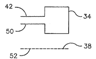
以下に、図2から図6を用いて、本発明の範囲に含まれるリーダアンテナ34、38の多様な配置について説明する。なお、アンテナ34、38それぞれは、矩形の形状を構成する単巻線(winding)を用いて簡潔に示しているが、これによって本発明が制限されるものではない。さらに、図2から図6では、リーダ低周波数アンテナ34は、実線で表し、一方、リーダ高周波数アンテナは、点線で表している。しかしながら、これに代えて、実線は、高周波数アンテナ38を表し、一方、点線は、低周波数アンテナ34を表すようにすることもできる。
Hereinafter, various arrangements of the
一般に、リーダアンテナ34、38は、RFIDリーダ14のハウジング54(図1に示している)内に、リーダアンテナ34、38を固定して取り付けることによって、操作上好ましい配置がなされる。リーダハウジング54は、RFIDリーダ14の外側の囲いやシェルであり、例えば、硬質プラスチックのような材料から作られており、RFIDリーダ14の構成要素を含み、保護するものであり、実質的にRFIDリーダ14の操作性を損なわないものである。リーダハウジング54はできるだけコンパクトであることが望ましい。リーダハウジング54のサイズは、少なくともリーダアンテナ34、38の配置機能の一部に関係するのでリーダアンテナ34、38はそれが許容可能なコンパクトサイズのリーダハウジング54内に含まれるような方法で配置することが望まれる。
In general, the
リーダハウジング54内にリーダアンテナ34、38を近接させて設置することは、明らかに、リーダハウジング54に要求されるサイズを減少させる。しかしながら、リーダアンテナ34、38の特性を考慮しないで近接して設置することは、リーダアンテナ34とリーダアンテナ38との間で干渉が生じ、干渉は、相応してリーダアンテナ34、38それぞれの通信範囲を減少させる。典型的なRFIDリーダは、RFIDリーダから開放空間へ放射する検出シグナルと励振シグナルを包含する磁界の強さを最大にするために、所望の操作周波数における共振効果に依存している。共振効果は、特に、RFIDリーダの共振をおこす回路内におけるアンテナコイルのインダクタンスと同調用キャパシタの電気容量の機能である。複数のアンテナコイルのアレイ内で、二つのアンテナコイルが相互に近接して設置された場合、“寄生容量あるいは浮遊容量”と呼ばれる、小さな電気容量がアンテナコイルの間に生じる。供与されたアンテナコイルの寄生容量あるいは浮遊容量は、そのアンテナコイルのインダクタンスと結合して自己の共振効果を作り出す。この自己共振効果は、アンテナコイル設計には説明されるものではなくても、アンテナコイルから発生する磁界の強さを著しく弱め、よってアンテナコイルの通信範囲を著しく狭める。
Placing the
自己の共振効果は、二つのアンテナコイルが相互に極めて近接して設置された場合によって説明できる。シグナル生成部によって、第一のアンテナコイルが第一の同調用キャパシタと共同して動作すると、第一のアンテナコイルから磁界が発生する。少なくとも、この磁界の一部分が、基部に近いほうの第二のアンテナコイルを通り抜けるとき、磁界は、第二のアンテナコイルの自己共振に起因する第二のアンテナコイル内の電気活動を引き起こす。最悪の場合、第二のアンテナコイルは、第一の同調用キャパシタと結合する第一のアンテナコイルと同じ共振周波数となり、このことは、シグナル生成部からの最大のエネルギー量が第二のアンテナコイルへ流れ込み、第一のアンテナコイルの通信範囲が実質的に減少する。 The self-resonance effect can be explained by the case where two antenna coils are installed in close proximity to each other. When the first antenna coil operates in cooperation with the first tuning capacitor by the signal generator, a magnetic field is generated from the first antenna coil. At least when a portion of this magnetic field passes through the second antenna coil closer to the base, the magnetic field causes electrical activity in the second antenna coil due to self-resonance of the second antenna coil. In the worst case, the second antenna coil has the same resonance frequency as the first antenna coil coupled to the first tuning capacitor, which means that the maximum amount of energy from the signal generator is the second antenna coil. And the communication range of the first antenna coil is substantially reduced.
自己共振のより具体的なケースとして、第一及び第二のアンテナが近接して設置され、第一のアンテナコイルが低周波数(125kHz)リーダアンテナであり、一方、第二のアンテナコイルが高周波数(13.56MHz)リーダアンテナである場合を説明する。リーダ低周波数アンテナは、典型的には1ミリヘンリのインダクタンスを有する。共振周波数(ラジアンの)の二乗は、インダクタンスと電気容量の積に反比例するので、13.56MHzの自己共振のためのリーダ低周波数アンテナの電気容量は、約0.14ピコファラド(picofarads)となり、これは、寄生容量あるいは浮遊容量の範囲内である。このレベルの電気容量をコントロールすることは極めて難しく、また、13.56MHzあるいはこの近辺の周波数におけるリーダ低周波数アンテナの自己共振が、リーダ高周波数アンテナのオペレーションに干渉するのを防ぐことも同様に非常に難しい。 As a more specific case of self-resonance, the first and second antennas are placed close together, the first antenna coil is a low frequency (125 kHz) reader antenna, while the second antenna coil is a high frequency. The case of a (13.56 MHz) reader antenna will be described. A reader low frequency antenna typically has an inductance of 1 millihenry. The square of the resonant frequency (in radians) is inversely proportional to the product of inductance and capacitance, so the capacitance of the reader low frequency antenna for 13.56 MHz self-resonance is about 0.14 picofarads, Is within the range of parasitic capacitance or stray capacitance. It is extremely difficult to control this level of capacitance, and it is also very difficult to prevent the self-resonance of the reader low frequency antenna at or near 13.56 MHz from interfering with the operation of the reader high frequency antenna. It is difficult.
まず、図2A及び図2Bについて説明すると、リーダアンテナ34、38は、孤立した配置で示されている。リーダアンテナ34、38は、非接触で固定された同方向の交信角度(parallel orientation)を有し、本質的に同じ領域を有する。リーダアンテナ34、38相互を孤立させるために、また、他方で発生する著しい磁束を避けるために、リーダアンテナ34、38は、垂直方向及び水平方向に互いに十分離れるように配される。このようにして、自己共振の影響は、リーダ低周波数アンテナ34またはリーダ高周波数アンテナ38のいずれの通信範囲へも有害な影響をほとんど与えず、また同様に、RFIDリーダの性能へも有害な影響をほとんど与えない。一方、孤立した配置にするために、空間的な要件として比較的大きなリーダハウジングが必要となることは望ましくない。加えて、RFIDリーダとRFIDトランスポンダとの通信を最適化するために、利用者が、RFIDトランスポンダを、そのトランスポンダと対応するリーダアンテナ34あるいは38へより近づけるように操作する必要があることも望ましくない。
2A and 2B, the
オーバーラップ配置と呼ばれているアンテナ配置は、孤立した配置を実現する好ましい一例である。オーバーラップ配置では、リーダアンテナ34あるいは38が質量中心のあたりで固定された位置から回転すると想定した場合、リーダアンテナ34あるいは38のいずれか一方が、他方のリーダアンテナ38あるいは34と回転のいくつかのポイントで接触する配置となるように、二つのリーダアンテナ34、38は、動かないように取り付けられる。また、オーバーラップ配置には、動かないように取り付けられたリーダアンテナ34、38の両方が、それぞれの質量中心について固定された位置から回転すると想定した場合、リーダアンテナ34、38がお互いにいくつかの回転のポイントで接触するようになっている、というケースも含まれる。オーバーラップ配置では、回転するアンテナ群は、他方のリーダアンテナ38あるいは34、もしくは他方のアンテナ群の入力線42及び/または出力線50、あるいは、入力線44及び/または出力線52と接触することになるため、アンテナ群には、入力線42及び/または出力線50、あるいは、入力線44及び/または出力線52を備えていなくてもよい。
An antenna arrangement called an overlap arrangement is a preferable example for realizing an isolated arrangement. In the overlap arrangement, if it is assumed that the
さらに、磁束対向配置と呼ばれているアンテナ配置も、好ましい配置の一例である。磁束対向配置では、二つのリーダアンテナ34、38は、お互いが接触しない関係で、あるいは接触する関係で動かないように取り付けられ、リーダアンテナ34あるいは38によって生じた磁束が、他方のリーダアンテナ38あるいは34を対向する方式で通り抜ける(すなわち、一方のリーダアンテナ34あるいは38から生じた、正と負の両方の磁束が、他方のリーダアンテナ38あるいは34を通り抜ける)。本明細書では、正の磁束は、アンテナコイルに正の電圧を引き起こすものと定義する。また、負の磁束は、反対に、アンテナコイルに負の電圧を引き起こすものと定義する。また、磁束対向配置では、正の磁束と負の磁束は、同じ大きさでなくてもよい。さらに、オーバーラップ配置と磁束対向配置の両方の定義を同時に満たすアンテナの配置も可能である。
Further, an antenna arrangement called a magnetic flux opposing arrangement is an example of a preferable arrangement. In the arrangement opposite to the magnetic flux, the two
次に、図3A及び図3Bについて説明すると、リーダアンテナ34、38は、磁束対向配置で示されている。リーダアンテナ34、38は、非接触で固定された同方向の交信角度(parallel orientation)を有し、リーダ低周波数アンテナ34は、リーダ高周波数アンテナ38より広い領域を有する。リーダアンテナ34、38は、リーダ高周波数アンテナ38の領域が、リーダ低周波数アンテナ34の領域の中に組み込まれるような関係で互いに配置される。リーダ高周波数アンテナ38によって生じる負の方向の磁束(すなわち、リーダ高周波数アンテナ38の外側から発する磁束)は、リーダ低周波数アンテナ34を通り抜ける。また、リーダ高周波数アンテナ38によって生じる正の方向の磁束(すなわち、リーダ高周波数アンテナ38の内側から発する磁束)も、リーダ低周波数アンテナ34を通り抜ける。その結果、リーダ高周波数アンテナ38で生じてリーダ低周波数アンテナ34を通り抜ける、正の磁束及び負の磁束は、相殺され、合計して本質的に零になる。このようにして、本質的には、リーダ高周波数アンテナ38の磁束によるリーダ低周波数アンテナ34の自己共振の影響がなくなる。
Next, referring to FIGS. 3A and 3B, the
図3A及び図3Bのケースでは、逆は成立しない。リーダ低周波数アンテナ34によって生じる正の方向の磁束(すなわち、リーダ低周波数アンテナ34の内側から発する磁束)のみが、リーダ高周波数アンテナ38を通り抜ける。その結果、リーダ低周波数アンテナ34で生じてリーダ高周波数アンテナ38を通り抜ける、正の磁束及び負の磁束は、合計して零にすることにより相殺されることはない。従って、リーダ低周波数アンテナ34の磁束によるリーダ高周波数アンテナ38の自己共振の影響が存在することになる。
In the case of FIGS. 3A and 3B, the reverse is not true. Only the positive direction magnetic flux generated by the reader low frequency antenna 34 (ie, the magnetic flux emanating from the inside of the reader low frequency antenna 34) passes through the reader
図4A及び図4Bについて説明すると、リーダアンテナ34、38は、オーバーラップ配置で示されている。リーダアンテナ34、38は、非接触で固定された同方向の交信角度(parallel orientation)を有し、それぞれは本質的に同じ領域を有する。リーダアンテナ34、38は、リーダ低周波数アンテナ34の領域が、リーダ高周波数アンテナ38の領域と本質的に重なるような関係で互いに配置される。その結果、リーダ低周波数アンテナ34が質量中心の周りで回転すると想定した場合、リーダ低周波数アンテナ34は、リーダ高周波数アンテナ38と接触するようになる。同様に、リーダ高周波数アンテナ38が質量中心の周りで回転すると想定した場合、リーダ高周波数アンテナ38は、リーダ低周波数アンテナ34と接触するようになる。
Referring to FIGS. 4A and 4B, the
リーダ低周波数アンテナ34によって生じる正の方向の磁束のみ、リーダ高周波数アンテナ38を通り抜ける。同様に、リーダ高周波数アンテナ38によって生じる正の方向の磁束のみ、リーダ低周波数アンテナ34を通り抜ける。その結果、リーダ低周波数アンテナ34で生じてリーダ高周波数アンテナ38を通り抜ける磁束、並びに、リーダ高周波数アンテナ38で生じてリーダ低周波数アンテナ34を通り抜ける磁束のいずれも、相殺されることはない。従って、リーダ高周波数アンテナ38の磁束によるリーダ低周波数アンテナ34の自己共振の影響は、リーダ低周波数アンテナ34の磁束によるリーダ高周波数アンテナ38の自己共振の影響と同様に存在することになる。
Only the positive direction magnetic flux generated by the reader
図3A及び図3B、並びに、図4A及び図4Bに示したアンテナの配置は、それぞれ、リーダアンテナ34、38の近接する設置を可能にするとともに、同様に、リーダハウジングを小さくすることができる。しかしながら、どちらも自己共振によるリーダアンテナのエネルギーの喪失を完全に避けるものではないので、いずれの配置も最適というわけではない。
The antenna arrangements shown in FIGS. 3A and 3B and FIGS. 4A and 4B allow the
図5A及び図5Bについて説明すると、リーダアンテナ34、38は、オーバーラップ配置で示されている。リーダアンテナ34、38は、非接触で固定された直角をなす交信角度(perpendicular orientation)を有し、それぞれは本質的に同じ領域を有する。リーダアンテナ34、38は、直角をなすようにして、並んで取り付けられる。この配置は、リーダ低周波数アンテナ34の磁束によるリーダ高周波数アンテナ38の自己共振の顕著な影響を本質的になくし、同様にリーダ高周波数アンテナ38の磁束によるリーダ低周波数アンテナ34の自己共振の顕著な影響を本質的になくすという結果をもたらす。このように、自己共振の影響は、リーダ低周波数アンテナ34あるいはリーダ高周波数アンテナ38のいずれの通信範囲にも有害な影響をほとんど与えず、また同様に、RFIDリーダの性能へ有害な影響をほとんど与えない。一方で、図2A及び図2Bの配置と同様に、この配置にするために、空間的な要件として比較的大きなリーダハウジングが必要となることは望ましくない。加えて、RFIDリーダとRFIDトランスポンダとの通信を最適化するために、利用者が、RFIDトランスポンダを、そのトランスポンダと対応するリーダアンテナ34あるいは38へ、より近づけるように操作する必要があることも望ましくない。
Referring to FIGS. 5A and 5B, the
図6A及び図6Bについて説明すると、リーダアンテナ34、38は、オーバーラップ配置と磁束対向配置とを同時に取り入れた配置で示されている。リーダアンテナ34、38は、非接触で固定された同方向の交信角度(parallel orientation)を有し、それぞれは本質的に同じ全体領域を有する。リーダアンテナ34、38は、リーダ低周波数アンテナ34の全体領域の本質的に半分がリーダ高周波数アンテナ38の全体領域の本質的に半分と重なるような関係で互いに配置される。その結果、リーダ低周波数アンテナ34が質量中心の周りで回転すると、リーダ低周波数アンテナ34は、リーダ高周波数アンテナ38と接触するようになる。同様に、仮にリーダ高周波数アンテナ38が質量中心の周りで回転すると、リーダ高周波数アンテナ38は、リーダ低周波数アンテナ34と接触することになる。
Referring to FIGS. 6A and 6B, the
リーダ低周波数アンテナ34より生じる同じ大きさの正の方向と負の方向の磁束は、リーダ高周波数アンテナ38を通り抜け、同様に、リーダ高周波数アンテナ38より生じる同じ大きさの正の方向と負の方向の磁束は、リーダ低周波数アンテナ34を通り抜ける。その結果、リーダ低周波数アンテナ34で生じてリーダ高周波数アンテナ38を通り抜ける磁束と、リーダ高周波数アンテナ38で生じてリーダ低周波数アンテナ34を通り抜ける磁束とは、本質的に完全に相殺される。従って、リーダ高周波数アンテナ38の磁束によるリーダ低周波数アンテナ34の自己共振の影響は本質的になくなり、リーダ低周波数アンテナ34の磁束によるリーダ高周波数アンテナ38の自己共振の影響も本質的になくなる。このように、自己共振の影響は、リーダ低周波数アンテナ34あるいはリーダ高周波数アンテナ38のいずれの通信範囲にも有害な影響をほとんど与えず、また同様に、RFIDリーダの性能へ有害な影響をほとんど与えない。
The same magnitude positive and negative magnetic fluxes generated from the reader
図6A及び図6Bに示す配置の空間的な要件は、比較的小さく、よって、比較的小さなリーダハウジングを可能とする。加えて、リーダアンテナ34、38の領域は、RFIDトランスポンダを組み込むカード23a(あるいは、図に示していないが23b)の領域と同じようになる。よって、リーダアンテナ34、38を囲むリーダハウジングの領域は、カード23aの領域と同じようになる。従って、利用者は、手動でRFIDトランスポンダをリーダハウジングに重ねるという簡単な操作によって、RFIDトランスポンダとリーダアンテナ34、38とを重ねることになり、RFIDリーダとRFIDトランスポンダとの通信を最適化することができる。
The spatial requirements of the arrangement shown in FIGS. 6A and 6B are relatively small, thus allowing a relatively small reader housing. In addition, the area of the
図6A及び図6Bに示したオーバーラップ配置と磁束対向配置とを同時に取り入れたリーダアンテナ34、38の配置は、本発明のオーバーラップ配置と磁束対向配置とを同時に取り入れたリーダアンテナ34、38の配置の特徴を表す一例にすぎず、リーダ低周波数アンテナ34が、リーダ低周波数アンテナ34の全体領域より実質上小さいオーバーラップ領域を有し、リーダ高周波数アンテナ38が、リーダ高周波数アンテナ38の全体領域より実質上小さいオーバーラップ領域を有する例を示したものである。言い換えれば、リーダ低周波数アンテナ34とリーダ高周波数アンテナ38とは、リーダ低周波数アンテナ34の全体領域の一部分とリーダ高周波数アンテナ38の全体領域の一部分のみが重なるように相互に配置されているともいえる。
The arrangement of the
リーダアンテナ34、38において、上記で一般化して記載したオーバーラップ配置と磁束対向配置との併用に係る特徴は、追加記載する特有の代替アンテナ配置をも網羅し含み、それは図示してはいないものの本発明の範囲に含まれる。例えば、上記で一般化して記載した特徴は、リーダアンテナ34、38が、それぞれの全体領域より実質上小さいオーバーラップ領域をそれぞれ有し、リーダアンテナ34、38それぞれの全体領域は実質上相互に異なる、という特有のアンテナ配置を含む。さらに、上記で一般化して記載した特徴は、リーダアンテナ34、38が、それぞれの全体領域より実質上小さいオーバーラップ領域をそれぞれ有し、リーダアンテナ34、38それぞれのオーバーラップ領域は、実質上相互に異なる、という特有のアンテナ配置を含む。
In the
上記で説明した特有の代替アンテナ配置は、リーダ高周波数アンテナ38の磁束によるリーダ低周波数アンテナ34の自己共振の影響を除去することと、リーダ低周波数アンテナ34の磁束によるリーダ高周波数アンテナ38の自己共振の影響を除去することとの両方あるいはいずれかに関して、図6A及び図6Bに示す特有のアンテナ配置と同じように有効であるわけではない。それでもなお、特有の代替アンテナ配置は、許容できる程度に小型で経済的で、性能的にも満足できる互換性の広いRFIDリーダを提供することができる。
The particular alternative antenna arrangement described above eliminates the effect of the self-resonance of the reader
以上、本発明の好適な実施の形態について説明及び図解してきたが、これにより示唆されるような修正や変更を加えることも可能であり、これらもまた本発明に含まれる。 Although the preferred embodiments of the present invention have been described and illustrated above, modifications and changes suggested thereby can be made and these are also included in the present invention.
Claims (11)
第二の高搬送周波数でデータ信号を送信する第二のトランスポンダと一体でデータ通信を可能にする、前記第一の低搬送周波数と異なる前記第二の高搬送周波数で動作するように同調させた第二のリーダアンテナと、 Tuned to operate at the second high carrier frequency different from the first low carrier frequency, allowing data communication to be integrated with a second transponder transmitting a data signal at a second high carrier frequency A second reader antenna,
を備え、With
前記第一及び第二のリーダアンテナは、The first and second reader antennas are
前記第二のリーダアンテナによって生じる正と負の両方向の磁束が、前記第一のリーダアンテナを通り抜けるような磁束対向配置に配置され、The positive and negative magnetic fluxes generated by the second reader antenna are arranged in a magnetic flux facing arrangement so as to pass through the first reader antenna,
前記第一及び第二のリーダアンテナのそれぞれの全体領域よりも小さい領域で互いにオーバーラップするように配置される、Arranged to overlap each other in an area smaller than the entire area of each of the first and second reader antennas,
ことを特徴とするRFIDリーダ。RFID reader characterized by the above.
Applications Claiming Priority (4)
| Application Number | Priority Date | Filing Date | Title |
|---|---|---|---|
| US10/848,246 US7180403B2 (en) | 2004-05-18 | 2004-05-18 | RFID reader utilizing an analog to digital converter for data acquisition and power monitoring functions |
| US10/848,246 | 2004-05-18 | ||
| US11/016,576 | 2004-12-16 | ||
| US11/016,576 US7439862B2 (en) | 2004-05-18 | 2004-12-16 | Antenna array for an RFID reader compatible with transponders operating at different carrier frequencies |
Related Parent Applications (1)
| Application Number | Title | Priority Date | Filing Date |
|---|---|---|---|
| JP2005143698A Division JP4815148B2 (en) | 2004-05-18 | 2005-05-17 | RFID reader antenna array compatible with transponders operating at different carrier frequencies |
Publications (2)
| Publication Number | Publication Date |
|---|---|
| JP2009169992A JP2009169992A (en) | 2009-07-30 |
| JP5043062B2 true JP5043062B2 (en) | 2012-10-10 |
Family
ID=34941326
Family Applications (2)
| Application Number | Title | Priority Date | Filing Date |
|---|---|---|---|
| JP2005143698A Active JP4815148B2 (en) | 2004-05-18 | 2005-05-17 | RFID reader antenna array compatible with transponders operating at different carrier frequencies |
| JP2009113070A Active JP5043062B2 (en) | 2004-05-18 | 2009-05-07 | RFID reader antenna array compatible with transponders operating at different carrier frequencies |
Family Applications Before (1)
| Application Number | Title | Priority Date | Filing Date |
|---|---|---|---|
| JP2005143698A Active JP4815148B2 (en) | 2004-05-18 | 2005-05-17 | RFID reader antenna array compatible with transponders operating at different carrier frequencies |
Country Status (7)
| Country | Link |
|---|---|
| US (1) | US7439862B2 (en) |
| EP (1) | EP1605391B1 (en) |
| JP (2) | JP4815148B2 (en) |
| AU (1) | AU2005202015B9 (en) |
| CA (1) | CA2507277C (en) |
| DE (1) | DE602005013321D1 (en) |
| ES (1) | ES2324223T3 (en) |
Families Citing this family (120)
| Publication number | Priority date | Publication date | Assignee | Title |
|---|---|---|---|---|
| US7325723B2 (en) * | 2001-05-14 | 2008-02-05 | Em Microelectronic-Marin Sa | System and method for detecting persons or objects in definite areas provided each with at least an entrance |
| US7686229B2 (en) * | 2003-01-30 | 2010-03-30 | Hewlett-Packard Development Company, L.P. | RFID reader device having closely packed antennas |
| KR20050123174A (en) * | 2003-04-21 | 2005-12-29 | 심볼테크놀로지스,인코포레이티드 | Method for optimizing the design and implementation of rfid tags |
| US7676839B2 (en) * | 2004-03-15 | 2010-03-09 | Xceedid | Systems and methods for access control |
| KR100682867B1 (en) * | 2004-06-04 | 2007-02-15 | 삼성전기주식회사 | Automatic document moving system and method |
| US7614556B2 (en) * | 2004-11-05 | 2009-11-10 | Goliath Solutions, Llc | Distributed RFID antenna array utilizing circular polarized helical antennas |
| US7535337B2 (en) * | 2004-11-18 | 2009-05-19 | Goliath Solutions, Llc | Systems and methods for monitoring open stock merchandising |
| US20070071131A1 (en) * | 2004-11-18 | 2007-03-29 | Pyne John W | Switched phase receiver for a long range RFID system |
| WO2006055667A2 (en) | 2004-11-19 | 2006-05-26 | Goliath Solutions L.L.C. | Low stock alert system |
| US7900253B2 (en) | 2005-03-08 | 2011-03-01 | Xceedid Corporation | Systems and methods for authorization credential emulation |
| WO2006097760A1 (en) * | 2005-03-18 | 2006-09-21 | Innovision Research & Technology Plc | Communications device, apparatus and system |
| EP1910872B1 (en) * | 2005-07-28 | 2011-06-29 | Tagsys SAS | Rfid tag containing two tuned circuits |
| EP1932213B1 (en) * | 2005-09-12 | 2020-11-25 | Sato Holdings Corporation | Antenna design and interrogator system |
| US20070075142A1 (en) * | 2005-09-30 | 2007-04-05 | Symbol Technologies, Inc. | Mobile computer with integrated UHF RFID reader |
| US20070115130A1 (en) * | 2005-11-14 | 2007-05-24 | Ronald Eveland | Multi-dimensional, broadband track and trace sensor radio frequency identification device |
| US20070262866A1 (en) * | 2005-11-14 | 2007-11-15 | Ronald Eveland | Multi-Dimensional Broadband Track and Trace Sensor Radio Frequency Identification Device |
| US20070229264A1 (en) * | 2005-11-14 | 2007-10-04 | Ronald Eveland | Software method and system for encapsulation of RFID data into a standardized globally routable format |
| US7456743B2 (en) * | 2005-12-07 | 2008-11-25 | Datamars S.A. | Combined low and high frequency RFID system |
| WO2007073099A1 (en) * | 2005-12-22 | 2007-06-28 | Lg Innotek Co., Ltd | Rfid system |
| US20070188327A1 (en) * | 2006-02-16 | 2007-08-16 | Ncr Corporation | Radio frequency device |
| US20070221730A1 (en) * | 2006-03-27 | 2007-09-27 | Mcreynolds Alan | RFID enabled cable tracking |
| US7806333B1 (en) | 2006-03-27 | 2010-10-05 | Hewlett-Packard Development Company, L.P. | Tracking RFID tags with overlapping antennas |
| KR101189400B1 (en) | 2006-03-31 | 2012-10-10 | 엘지이노텍 주식회사 | RFID Reader |
| US8063746B2 (en) * | 2006-03-31 | 2011-11-22 | Assa Abloy Ab | Transponder detector for an RFID system generating a progression of detection signals |
| US7782209B2 (en) * | 2006-03-31 | 2010-08-24 | Assa Abloy Ab | Detection signal generator circuit for an RFID reader |
| US20070229269A1 (en) * | 2006-04-03 | 2007-10-04 | Intermec Ip Corp. | System and method for mitigating interference by radio frequency identification and electronic article surveillance systems with implantable cardiac devices |
| EP1873692B1 (en) | 2006-06-29 | 2011-12-21 | Semiconductor Energy Laboratory Co., Ltd. | Semiconductor device |
| US7760093B2 (en) * | 2006-07-26 | 2010-07-20 | Broadcom Corporation | RFID interface and applications thereof |
| AU2006346817A1 (en) * | 2006-08-01 | 2008-02-07 | Agency For Science, Technology And Research | Antenna for near field and far field radio frequency identification |
| US11557163B2 (en) | 2006-08-16 | 2023-01-17 | Isonas, Inc. | System and method for integrating and adapting security control systems |
| US9153083B2 (en) | 2010-07-09 | 2015-10-06 | Isonas, Inc. | System and method for integrating and adapting security control systems |
| US7775429B2 (en) | 2006-08-16 | 2010-08-17 | Isonas Security Systems | Method and system for controlling access to an enclosed area |
| US9589400B2 (en) | 2006-08-16 | 2017-03-07 | Isonas, Inc. | Security control and access system |
| DE102006058318B4 (en) * | 2006-12-11 | 2011-06-16 | Siemens Audiologische Technik Gmbh | Control method for a hearing device with transponder recognition |
| JP4784763B2 (en) * | 2006-12-20 | 2011-10-05 | 株式会社日立プラントテクノロジー | RFID tag, construction site management system and management method using the same |
| WO2008093334A2 (en) | 2007-01-29 | 2008-08-07 | Powermat Ltd | Pinless power coupling |
| GB2449650A (en) * | 2007-05-30 | 2008-12-03 | Ritag | RFID marker |
| WO2009022324A2 (en) * | 2007-08-13 | 2009-02-19 | Mti Wireless Edge Ltd. | Antenna for near field radio-frequency identification and method and system for use thereof |
| FI20075942L (en) * | 2007-12-20 | 2009-06-21 | Valtion Teknillinen | RFID reading device and method of an RFID reading device |
| AT506438B1 (en) * | 2008-01-22 | 2012-04-15 | Evva Sicherheitstechnologie | READER FOR NAHFELD OR RFID APPLICATIONS |
| EP2107495B1 (en) * | 2008-04-01 | 2012-09-19 | Assa Abloy Ab | Switched capacitance method for the detection of, and subsequent communication with a wireless transponder device using a single antenna |
| ITTO20080355A1 (en) * | 2008-05-13 | 2009-11-14 | N & W Innovative Solutions S R L | KEY READER AND / OR MEMORY CARD READER FOR AUTOMATIC DISTRIBUTORS |
| AU2009257187C1 (en) | 2008-06-12 | 2020-04-02 | Sato Holdings Corporation | Antenna design and interrogator system |
| US8713697B2 (en) | 2008-07-09 | 2014-04-29 | Lennox Manufacturing, Inc. | Apparatus and method for storing event information for an HVAC system |
| US8579195B2 (en) | 2008-08-25 | 2013-11-12 | Nxp B.V. | Reconfigurable radio-frequency front-end |
| US8527096B2 (en) | 2008-10-24 | 2013-09-03 | Lennox Industries Inc. | Programmable controller and a user interface for same |
| US8615326B2 (en) | 2008-10-27 | 2013-12-24 | Lennox Industries Inc. | System and method of use for a user interface dashboard of a heating, ventilation and air conditioning network |
| US8855825B2 (en) | 2008-10-27 | 2014-10-07 | Lennox Industries Inc. | Device abstraction system and method for a distributed-architecture heating, ventilation and air conditioning system |
| US8744629B2 (en) | 2008-10-27 | 2014-06-03 | Lennox Industries Inc. | System and method of use for a user interface dashboard of a heating, ventilation and air conditioning network |
| US8655491B2 (en) | 2008-10-27 | 2014-02-18 | Lennox Industries Inc. | Alarm and diagnostics system and method for a distributed architecture heating, ventilation and air conditioning network |
| US8694164B2 (en) | 2008-10-27 | 2014-04-08 | Lennox Industries, Inc. | Interactive user guidance interface for a heating, ventilation and air conditioning system |
| US8798796B2 (en) * | 2008-10-27 | 2014-08-05 | Lennox Industries Inc. | General control techniques in a heating, ventilation and air conditioning network |
| US8548630B2 (en) | 2008-10-27 | 2013-10-01 | Lennox Industries, Inc. | Alarm and diagnostics system and method for a distributed-architecture heating, ventilation and air conditioning network |
| US8977794B2 (en) | 2008-10-27 | 2015-03-10 | Lennox Industries, Inc. | Communication protocol system and method for a distributed-architecture heating, ventilation and air conditioning network |
| US8600558B2 (en) | 2008-10-27 | 2013-12-03 | Lennox Industries Inc. | System recovery in a heating, ventilation and air conditioning network |
| US8802981B2 (en) | 2008-10-27 | 2014-08-12 | Lennox Industries Inc. | Flush wall mount thermostat and in-set mounting plate for a heating, ventilation and air conditioning system |
| US9268345B2 (en) | 2008-10-27 | 2016-02-23 | Lennox Industries Inc. | System and method of use for a user interface dashboard of a heating, ventilation and air conditioning network |
| US8452906B2 (en) | 2008-10-27 | 2013-05-28 | Lennox Industries, Inc. | Communication protocol system and method for a distributed-architecture heating, ventilation and air conditioning network |
| US8661165B2 (en) | 2008-10-27 | 2014-02-25 | Lennox Industries, Inc. | Device abstraction system and method for a distributed architecture heating, ventilation and air conditioning system |
| US9432208B2 (en) | 2008-10-27 | 2016-08-30 | Lennox Industries Inc. | Device abstraction system and method for a distributed architecture heating, ventilation and air conditioning system |
| US8994539B2 (en) | 2008-10-27 | 2015-03-31 | Lennox Industries, Inc. | Alarm and diagnostics system and method for a distributed-architecture heating, ventilation and air conditioning network |
| US8560125B2 (en) | 2008-10-27 | 2013-10-15 | Lennox Industries | Communication protocol system and method for a distributed-architecture heating, ventilation and air conditioning network |
| US8655490B2 (en) | 2008-10-27 | 2014-02-18 | Lennox Industries, Inc. | System and method of use for a user interface dashboard of a heating, ventilation and air conditioning network |
| US8442693B2 (en) | 2008-10-27 | 2013-05-14 | Lennox Industries, Inc. | System and method of use for a user interface dashboard of a heating, ventilation and air conditioning network |
| US8874815B2 (en) | 2008-10-27 | 2014-10-28 | Lennox Industries, Inc. | Communication protocol system and method for a distributed architecture heating, ventilation and air conditioning network |
| US8437878B2 (en) | 2008-10-27 | 2013-05-07 | Lennox Industries Inc. | Alarm and diagnostics system and method for a distributed architecture heating, ventilation and air conditioning network |
| US8774210B2 (en) | 2008-10-27 | 2014-07-08 | Lennox Industries, Inc. | Communication protocol system and method for a distributed-architecture heating, ventilation and air conditioning network |
| US8437877B2 (en) | 2008-10-27 | 2013-05-07 | Lennox Industries Inc. | System recovery in a heating, ventilation and air conditioning network |
| US9678486B2 (en) | 2008-10-27 | 2017-06-13 | Lennox Industries Inc. | Device abstraction system and method for a distributed-architecture heating, ventilation and air conditioning system |
| US8600559B2 (en) | 2008-10-27 | 2013-12-03 | Lennox Industries Inc. | Method of controlling equipment in a heating, ventilation and air conditioning network |
| US9632490B2 (en) | 2008-10-27 | 2017-04-25 | Lennox Industries Inc. | System and method for zoning a distributed architecture heating, ventilation and air conditioning network |
| US8725298B2 (en) | 2008-10-27 | 2014-05-13 | Lennox Industries, Inc. | Alarm and diagnostics system and method for a distributed architecture heating, ventilation and conditioning network |
| US8295981B2 (en) | 2008-10-27 | 2012-10-23 | Lennox Industries Inc. | Device commissioning in a heating, ventilation and air conditioning network |
| US9325517B2 (en) | 2008-10-27 | 2016-04-26 | Lennox Industries Inc. | Device abstraction system and method for a distributed-architecture heating, ventilation and air conditioning system |
| US9651925B2 (en) | 2008-10-27 | 2017-05-16 | Lennox Industries Inc. | System and method for zoning a distributed-architecture heating, ventilation and air conditioning network |
| US8762666B2 (en) | 2008-10-27 | 2014-06-24 | Lennox Industries, Inc. | Backup and restoration of operation control data in a heating, ventilation and air conditioning network |
| US8564400B2 (en) | 2008-10-27 | 2013-10-22 | Lennox Industries, Inc. | Communication protocol system and method for a distributed-architecture heating, ventilation and air conditioning network |
| US8892797B2 (en) | 2008-10-27 | 2014-11-18 | Lennox Industries Inc. | Communication protocol system and method for a distributed-architecture heating, ventilation and air conditioning network |
| US8788100B2 (en) | 2008-10-27 | 2014-07-22 | Lennox Industries Inc. | System and method for zoning a distributed-architecture heating, ventilation and air conditioning network |
| US8433446B2 (en) | 2008-10-27 | 2013-04-30 | Lennox Industries, Inc. | Alarm and diagnostics system and method for a distributed-architecture heating, ventilation and air conditioning network |
| US8543243B2 (en) | 2008-10-27 | 2013-09-24 | Lennox Industries, Inc. | System and method of use for a user interface dashboard of a heating, ventilation and air conditioning network |
| US8452456B2 (en) | 2008-10-27 | 2013-05-28 | Lennox Industries Inc. | System and method of use for a user interface dashboard of a heating, ventilation and air conditioning network |
| US8463442B2 (en) | 2008-10-27 | 2013-06-11 | Lennox Industries, Inc. | Alarm and diagnostics system and method for a distributed architecture heating, ventilation and air conditioning network |
| US8463443B2 (en) | 2008-10-27 | 2013-06-11 | Lennox Industries, Inc. | Memory recovery scheme and data structure in a heating, ventilation and air conditioning network |
| US8872662B2 (en) * | 2009-02-12 | 2014-10-28 | Haldor Advanced Technologies Ltd. | Antenna, apparatus and method for identifying and tracking multiple items |
| JP5201005B2 (en) * | 2009-03-03 | 2013-06-05 | 富士通株式会社 | Wireless tag control method, wireless tag, and wireless tag control program |
| WO2010120807A1 (en) * | 2009-04-13 | 2010-10-21 | Visible Assets, Inc | Low-frequency tag with separate transmit and receive antennas |
| FR2950151B1 (en) * | 2009-09-15 | 2011-10-21 | Commissariat Energie Atomique | METHOD AND SYSTEM FOR LOCATING A PERSON, RECORDING MEDIUM FOR THIS METHOD |
| EP2339501A1 (en) * | 2009-12-21 | 2011-06-29 | Nxp B.V. | Near field communication devices |
| KR20120112803A (en) | 2010-01-29 | 2012-10-11 | 가부시키가이샤 한도오따이 에네루기 켄큐쇼 | Semiconductor device and electronic device including the same |
| US9342716B2 (en) | 2010-02-04 | 2016-05-17 | Carefusion 303, Inc. | Software-defined multi-mode RFID read devices |
| JP2011227591A (en) * | 2010-04-16 | 2011-11-10 | Lixil Nittan Co Ltd | Ic card reader and ic card authentication system |
| EP2423847B1 (en) * | 2010-08-27 | 2013-03-27 | Psion Inc. | System and method for multiple reading interface with a simple RFID antenna |
| US8907760B2 (en) * | 2010-09-09 | 2014-12-09 | Nxp B.V. | Multiple-frequency solutions for remote access systems |
| US20120082963A1 (en) | 2010-09-30 | 2012-04-05 | Assa Abloy Ab | Antenna calculation interface |
| BR112013023412A2 (en) | 2011-03-17 | 2017-06-27 | Assa Abloy Ab | method for updating rfid readers in situ |
| JP5673262B2 (en) * | 2011-03-18 | 2015-02-18 | 富士電機株式会社 | Non-contact IC card reader |
| US9152912B2 (en) * | 2011-10-13 | 2015-10-06 | Asia Vital Components Co., Ltd. | Smart card capable of independently displaying information |
| CN103891046B (en) * | 2011-10-26 | 2016-05-04 | 株式会社村田制作所 | Telecommunication circuit |
| US20150090789A1 (en) * | 2012-01-05 | 2015-04-02 | Hid Global Gmbh | Calculated compensated magnetic antennas for different frequencies |
| DE102012202788A1 (en) * | 2012-02-23 | 2013-08-29 | Micro-Sensys Gmbh | Transponder arrangement, transmitting and receiving device and method for operating a transmitting and receiving device |
| JP6074789B2 (en) * | 2012-08-02 | 2017-02-08 | 昭和シェル石油株式会社 | Payment processing system, method, and computer program |
| US9767328B2 (en) | 2013-03-15 | 2017-09-19 | Assa Abloy Ab | Autonomous tuning method to improve radio frequency performance |
| DE102013111027A1 (en) * | 2013-10-04 | 2015-04-09 | Infineon Technologies Ag | Multi-frequency antenna for miniaturized applications |
| EP3068299B1 (en) * | 2013-11-14 | 2019-05-08 | Technische Universiteit Eindhoven | System for locating an object using an antenna array with partially overlapping coils |
| JP6318964B2 (en) * | 2014-08-08 | 2018-05-09 | 株式会社デンソーウェーブ | Card reader |
| US9558377B2 (en) | 2015-01-07 | 2017-01-31 | WaveLynx Technologies Corporation | Electronic access control systems including pass-through credential communication devices and methods for modifying electronic access control systems to include pass-through credential communication devices |
| US9805229B2 (en) * | 2015-10-15 | 2017-10-31 | International Business Machines Corporation | Location sensing using a radio frequency tag |
| GB2550103A (en) | 2016-03-10 | 2017-11-15 | Paxton Access Ltd | Dual frequency RFID reader |
| FR3067534A1 (en) * | 2017-06-09 | 2018-12-14 | Stmicroelectronics (Rousset) Sas | METHOD FOR CONTROLLING THE POWER LEVEL ISSUED BY A CONTACTLESS COMMUNICATION DEVICE, FOR EXAMPLE A READER, AND CONTACTLESS COMMUNICATION DEVICE THEREFOR |
| PL3246846T3 (en) * | 2017-06-19 | 2020-06-15 | Revenue Collection Systems France Sas | Communication system, service-provision system comprising such a communication system, and associated method |
| US10789797B2 (en) | 2017-09-22 | 2020-09-29 | Schlage Lock Company Llc | Peripheral controller in an access control system |
| JP7097164B2 (en) * | 2017-09-29 | 2022-07-07 | オムロン株式会社 | RFID system and information processing method |
| FR3072535B1 (en) * | 2017-10-17 | 2019-10-04 | Continental Automotive France | IMPEDANCE ADAPTATION METHOD BETWEEN A READER MOUNTED IN A MOTOR VEHICLE OPENER AND A MOBILE TERMINAL |
| FR3074379B1 (en) * | 2017-11-24 | 2020-11-13 | Continental Automotive France | AUTHENTICATION READER FOR AUTOMOTIVE VEHICLE OPENER |
| US10439656B2 (en) | 2017-11-28 | 2019-10-08 | Schlage Lock Company Llc | Communication circuit with single element antenna for multi-frequency applications |
| US10355723B2 (en) * | 2017-11-28 | 2019-07-16 | Schlage Lock Company Llc | Communication circuit with single element antenna for multi-frequency applications |
| US11030836B2 (en) * | 2018-11-19 | 2021-06-08 | Aisin Seiki Kabushiki Kaisha | Door lock system and handle of door for vehicle |
| US11017653B1 (en) * | 2020-03-31 | 2021-05-25 | Nagaraja Donti | Cell phone proximity alarm system |
| ES1299652Y (en) * | 2022-10-18 | 2023-08-02 | Hernandez Hernandez Eloy | Radio Frequency Tag Locator Device |
Family Cites Families (24)
| Publication number | Priority date | Publication date | Assignee | Title |
|---|---|---|---|---|
| JPS60171475A (en) | 1984-02-15 | 1985-09-04 | アイデンティフィケ−ション・デバイセス・インコ−ポレ−テッド | Discriminating system |
| NZ314269A (en) | 1992-11-18 | 1998-01-26 | British Tech Group | Transponder identification system transmits multiple simultaneous interrogation signals |
| US5347263A (en) | 1993-02-05 | 1994-09-13 | Gnuco Technology Corporation | Electronic identifier apparatus and method utilizing a single chip microcontroller and an antenna coil |
| GB9308718D0 (en) | 1993-04-27 | 1993-06-09 | Mpk Technology Limited | An indentification system |
| US5541574A (en) | 1993-12-22 | 1996-07-30 | Palomar Technologies Corporation | Transponder system for communicating with a vehicle tire |
| JPH07230560A (en) | 1994-02-18 | 1995-08-29 | Nippon Signal Co Ltd:The | Non-contact automatic ticket checking machine |
| JPH0973523A (en) * | 1995-09-04 | 1997-03-18 | Toshiba Corp | Information processor |
| US6476708B1 (en) | 1998-03-20 | 2002-11-05 | Hid Corporation | Detection of an RFID device by an RF reader unit operating in a reduced power state |
| EP1069526A3 (en) * | 1999-07-12 | 2005-03-30 | Matsushita Electric Industrial Co., Ltd. | Mobile body discrimination apparatus for rapidly acquiring respective data sets transmitted through modulation of reflected radio waves by transponders which are within a communication region of an interrogator apparatus |
| US6750771B1 (en) * | 2000-08-10 | 2004-06-15 | Savi Technology, Inc. | Antenna system and method for reading low frequency tags |
| JP2002076983A (en) | 2000-08-31 | 2002-03-15 | Toshiba Chem Corp | Data carrier system |
| US20030090367A1 (en) | 2000-12-20 | 2003-05-15 | Carroll Gary Thomas | Indentification reader |
| US7158030B2 (en) * | 2001-09-19 | 2007-01-02 | Avante International Technology | Medical assistance and tracking system and method employing smart tags |
| JP4845306B2 (en) | 2001-09-25 | 2011-12-28 | トッパン・フォームズ株式会社 | RF-ID inspection system |
| KR20040096522A (en) | 2002-01-09 | 2004-11-16 | 미드웨스트바코 코포레이션 | Intelligent station using multiple rf antennae and inventory control system and method incorporating same |
| US6700547B2 (en) | 2002-04-12 | 2004-03-02 | Digital Angel Corporation | Multidirectional walkthrough antenna |
| JP4016762B2 (en) | 2002-08-22 | 2007-12-05 | 凸版印刷株式会社 | Non-contact IC card and manufacturing method thereof |
| JP2004086381A (en) | 2002-08-23 | 2004-03-18 | Dainippon Printing Co Ltd | Positional information management system on product, production area proving method on product, and non-contact data carrier for recording positional information on product |
| JP2004187159A (en) * | 2002-12-05 | 2004-07-02 | Matsushita Electric Ind Co Ltd | Radio tag reader-writer |
| US7071791B1 (en) * | 2003-01-30 | 2006-07-04 | The United States Of America As Represented By The Secretary Of The Army | Automatic antenna-switching apparatus and system |
| US7119664B2 (en) * | 2003-09-17 | 2006-10-10 | Id Solutions, Inc. | Deep sleep in an RFID tag |
| US7119738B2 (en) * | 2004-03-01 | 2006-10-10 | Symbol Technologies, Inc. | Object location system and method using RFID |
| US7268687B2 (en) * | 2004-03-23 | 2007-09-11 | 3M Innovative Properties Company | Radio frequency identification tags with compensating elements |
| JP2005284455A (en) | 2004-03-29 | 2005-10-13 | Fujita Denki Seisakusho:Kk | Rfid system |
-
2004
- 2004-12-16 US US11/016,576 patent/US7439862B2/en not_active Expired - Lifetime
-
2005
- 2005-05-11 AU AU2005202015A patent/AU2005202015B9/en active Active
- 2005-05-13 CA CA2507277A patent/CA2507277C/en active Active
- 2005-05-17 DE DE602005013321T patent/DE602005013321D1/en active Active
- 2005-05-17 EP EP05253002A patent/EP1605391B1/en active Active
- 2005-05-17 JP JP2005143698A patent/JP4815148B2/en active Active
- 2005-05-17 ES ES05253002T patent/ES2324223T3/en active Active
-
2009
- 2009-05-07 JP JP2009113070A patent/JP5043062B2/en active Active
Also Published As
| Publication number | Publication date |
|---|---|
| US20050258966A1 (en) | 2005-11-24 |
| AU2005202015A1 (en) | 2005-12-08 |
| AU2005202015B2 (en) | 2010-11-11 |
| JP2009169992A (en) | 2009-07-30 |
| AU2005202015B9 (en) | 2010-12-09 |
| CA2507277A1 (en) | 2005-11-18 |
| DE602005013321D1 (en) | 2009-04-30 |
| EP1605391A1 (en) | 2005-12-14 |
| JP2006012129A (en) | 2006-01-12 |
| US7439862B2 (en) | 2008-10-21 |
| CA2507277C (en) | 2012-06-19 |
| JP4815148B2 (en) | 2011-11-16 |
| ES2324223T3 (en) | 2009-08-03 |
| EP1605391B1 (en) | 2009-03-18 |
Similar Documents
| Publication | Publication Date | Title |
|---|---|---|
| JP5043062B2 (en) | RFID reader antenna array compatible with transponders operating at different carrier frequencies | |
| CN100520800C (en) | Antenna array for an RFID reader compatible with transponders operating at different carrier frequencies | |
| US9024725B2 (en) | Communication terminal and information processing system | |
| JP5195263B2 (en) | Information transmission medium management system | |
| EP2294712B1 (en) | Method and apparatus for an enlarged wireless charging area | |
| US7262700B2 (en) | Inductive powering surface for powering portable devices | |
| US20090001930A1 (en) | Electronic apparatus and associated methods | |
| EP2071734A2 (en) | Communication apparatus | |
| JP2001076111A (en) | Resonance circuit | |
| US20100315389A1 (en) | Devices and methods related to a display assembly including an antenna | |
| JPWO2005017821A1 (en) | Reader / writer and mobile communication device | |
| JP3649374B2 (en) | Antenna device and card-like storage medium | |
| JP2003187195A (en) | System and method for non-contact communication, and non-contact communication card | |
| KR100750436B1 (en) | Wireless communication terminal | |
| JP2004320571A (en) | Portable apparatus with rfid function | |
| JP5117607B2 (en) | Portable radio | |
| JPH10105660A (en) | Radio communication medium, radio communication medium housing case and radio communication system | |
| JP5156609B2 (en) | Non-contact information medium | |
| CN105893902B (en) | Chip card reads equipment | |
| JP2021158538A (en) | Communication equipment, communication systems and control methods | |
| JP3115843B2 (en) | IC card system | |
| CN211238480U (en) | Integration device of wireless communication antenna module and bar code reading assembly | |
| JP2005192052A (en) | Non-contact reader/writer |
Legal Events
| Date | Code | Title | Description |
|---|---|---|---|
| A621 | Written request for application examination |
Free format text: JAPANESE INTERMEDIATE CODE: A621 Effective date: 20090604 |
|
| A131 | Notification of reasons for refusal |
Free format text: JAPANESE INTERMEDIATE CODE: A131 Effective date: 20111222 |
|
| A601 | Written request for extension of time |
Free format text: JAPANESE INTERMEDIATE CODE: A601 Effective date: 20120319 |
|
| A602 | Written permission of extension of time |
Free format text: JAPANESE INTERMEDIATE CODE: A602 Effective date: 20120323 |
|
| A521 | Request for written amendment filed |
Free format text: JAPANESE INTERMEDIATE CODE: A523 Effective date: 20120423 |
|
| TRDD | Decision of grant or rejection written | ||
| A01 | Written decision to grant a patent or to grant a registration (utility model) |
Free format text: JAPANESE INTERMEDIATE CODE: A01 Effective date: 20120615 |
|
| A01 | Written decision to grant a patent or to grant a registration (utility model) |
Free format text: JAPANESE INTERMEDIATE CODE: A01 |
|
| A61 | First payment of annual fees (during grant procedure) |
Free format text: JAPANESE INTERMEDIATE CODE: A61 Effective date: 20120711 |
|
| R150 | Certificate of patent or registration of utility model |
Ref document number: 5043062 Country of ref document: JP Free format text: JAPANESE INTERMEDIATE CODE: R150 Free format text: JAPANESE INTERMEDIATE CODE: R150 |
|
| FPAY | Renewal fee payment (event date is renewal date of database) |
Free format text: PAYMENT UNTIL: 20150720 Year of fee payment: 3 |
|
| R250 | Receipt of annual fees |
Free format text: JAPANESE INTERMEDIATE CODE: R250 |
|
| R250 | Receipt of annual fees |
Free format text: JAPANESE INTERMEDIATE CODE: R250 |
|
| R250 | Receipt of annual fees |
Free format text: JAPANESE INTERMEDIATE CODE: R250 |
|
| R250 | Receipt of annual fees |
Free format text: JAPANESE INTERMEDIATE CODE: R250 |
|
| R250 | Receipt of annual fees |
Free format text: JAPANESE INTERMEDIATE CODE: R250 |
|
| R250 | Receipt of annual fees |
Free format text: JAPANESE INTERMEDIATE CODE: R250 |
|
| R250 | Receipt of annual fees |
Free format text: JAPANESE INTERMEDIATE CODE: R250 |
|
| R250 | Receipt of annual fees |
Free format text: JAPANESE INTERMEDIATE CODE: R250 |
|
| R250 | Receipt of annual fees |
Free format text: JAPANESE INTERMEDIATE CODE: R250 |