JP5040398B2 - Car side body structure - Google Patents
Car side body structure Download PDFInfo
- Publication number
- JP5040398B2 JP5040398B2 JP2007086678A JP2007086678A JP5040398B2 JP 5040398 B2 JP5040398 B2 JP 5040398B2 JP 2007086678 A JP2007086678 A JP 2007086678A JP 2007086678 A JP2007086678 A JP 2007086678A JP 5040398 B2 JP5040398 B2 JP 5040398B2
- Authority
- JP
- Japan
- Prior art keywords
- vehicle body
- striker
- surface member
- body structure
- automobile
- Prior art date
- Legal status (The legal status is an assumption and is not a legal conclusion. Google has not performed a legal analysis and makes no representation as to the accuracy of the status listed.)
- Expired - Fee Related
Links
Images


Landscapes
- Body Structure For Vehicles (AREA)
Description
本発明は、自動車の側部車体構造に関し、車体構造の技術分野に属する。 The present invention relates to a side body structure of an automobile, and belongs to the technical field of the body structure.
センターピラー後方の車体側部上部には、クォータウインドが設けられる場合がある。また、該クォータウインド下方の車体側部内面を構成する車体内面部材には、車体の軽量化等のために開口部が設けられる場合がある。 A quarter window may be provided at the upper part of the side of the vehicle body behind the center pillar. Further, an opening may be provided in the vehicle body inner surface member constituting the vehicle body side inner surface below the quarter window in order to reduce the weight of the vehicle body.
ところで、クォータウインドの側方には、例えばリヤシートが設けられると共に、該リヤシートのシートバックが可倒式のものである場合、該リヤシートを起立状態に保持するロック装置が車体側部との間に設けられることがある。このロック装置は、例えば、リヤシートの側部に設けられたラッチと、車体側部に設けられたストライカとにより構成されるが、このストライカは、例えば、特許文献1に開示されているように、前記車体内面部材における前記開口部の上部後方の部位に固定されることがある。 By the way, on the side of the quarter window, for example, a rear seat is provided, and when the seat back of the rear seat is of a retractable type, a locking device that holds the rear seat in an upright state is provided between the side of the vehicle body. May be provided. This locking device is composed of, for example, a latch provided on the side portion of the rear seat and a striker provided on the side portion of the vehicle body. This striker is, for example, disclosed in Patent Document 1, The vehicle body inner surface member may be fixed to a portion of the upper rear portion of the opening.
一方、前述のように車体内面部材に開口部が設けられた構造では、車体側部の強度が低下しやいため、特許文献2に開示されているように、該車体内面部材におけるクォータウインドの下縁に沿う部位にベルトラインレインフォースメントが設けられることがある。 On the other hand, in the structure in which the opening portion is provided in the vehicle body inner surface member as described above, the strength of the vehicle body side portion is likely to decrease. Therefore, as disclosed in Patent Document 2, the vehicle body inner surface member has a lower part of the quarter window. A beltline reinforcement may be provided along the edge.
ところで、リヤシートに乗員が着座した状態においては、リヤシートに後向きの荷重が加わり、この荷重がロック装置のストライカを介して車体内面部材に加わることとなるが、このときロック装置のストライカには車幅方向内側に引っ張る力も加わり、車体内面部材におけるストライカの固定部が車幅方向内側に変位する。そして、この状態が繰り返し生じると、ロック装置のラッチとストライカとが噛み合いにくくなる等の問題が生じる。なお、特許文献2に記載のもののようにベルトラインレインフォースメントが設けられていたとしても、ストライカとの位置関係によっては、この変位を十分に抑制することができない。 By the way, in the state where an occupant is seated on the rear seat, a rearward load is applied to the rear seat, and this load is applied to the vehicle body inner member via the striker of the lock device. A force pulling inward in the direction is also applied, and the fixed portion of the striker in the vehicle body inner surface member is displaced inward in the vehicle width direction. If this state occurs repeatedly, problems such as the latch of the locking device and the striker becoming difficult to mesh with each other arise. Even if a belt line reinforcement is provided as in the case of Patent Document 2, this displacement cannot be sufficiently suppressed depending on the positional relationship with the striker.
そこで、本発明は、ストライカが固定される部位における車体内面部材の変位を抑制可能な自動車の側部車体構造を提供することを課題とする。 Then, this invention makes it a subject to provide the side part vehicle body structure of the motor vehicle which can suppress the displacement of the vehicle body inner surface member in the site | part to which a striker is fixed.
前記課題を解決するために、本発明は、次のように構成したことを特徴とする。 In order to solve the above-described problems, the present invention is configured as follows.
まず、本願の請求項1に記載の発明は、センターピラー後方の車体側部上部にクォータウインドが設けられていると共に、該クォータウインド下方の車体側部内面を構成する車体内面部材に開口部が設けられ、かつ該車体内面部材における開口部の上部後方の部位に、シートバックの側部に設けられたラッチと係合することにより、シートバックを起立状態にロックするストライカが固定された自動車の側部車体構造であって、前記車体内面部材における開口部の上方部分が、ベルトラインレインフォースメントにより構成されていると共に、前記車体内面部材におけるストライカが固定される部位に補強部材が取り付けられており、かつ、前記ストライカは、前記ベルトラインレインフォースメントの下方後方において、前記シートバックを後傾姿勢の起立状態でロックするために後下がりに傾斜させて設けられていると共に、前記ベルトラインレインフォースメントは、前記ストライカに向って後方下方に延長されて、該延長部が前記補強部材と連結されていることを特徴とする。 In the first aspect of the present invention, a quarter window is provided at the upper part of the vehicle body side portion behind the center pillar, and an opening is formed in the vehicle body inner surface member constituting the vehicle body side portion inner surface below the quarter window. Of a vehicle in which a striker that locks the seat back in an upright state by being engaged with a latch provided on a side portion of the seat back is provided at a position behind the opening of the vehicle body inner surface member. In the side body structure, the upper portion of the opening in the inner surface member of the vehicle body is configured by a beltline reinforcement, and a reinforcing member is attached to a portion of the inner surface member of the vehicle body where the striker is fixed. cage, and the striker is at the lower rear of the beltline reinforcement, the seat back Together provided by inclining rearwardly and downwardly in order to lock in an upright state of the backward inclined posture, the beltline reinforcement is extended rearwardly downward toward the striker, said extension portion said reinforcing member It is connected with.
ここで、前記車体内面部材における開口部の上方部分が、ベルトラインレインフォースメントにより構成されていることには、この上方部分がベルトラインレインフォースメントのみにより構成されている場合と、ベルトラインレインフォースメントが加えられる場合との両方を含む。 Here, the upper part of the opening in the vehicle body inner surface member is constituted by a belt line reinforcement. This upper part is constituted only by the belt line reinforcement and the belt line reinforcement. This includes both cases where force is added.
また、請求項2に記載の発明は、前記請求項1に記載の自動車の側部車体構造において、前記ベルトラインレインフォースメントの延長部に前後に延びるビードが設けられていることを特徴とする。 The invention according to claim 2, in vehicle side body structure according to claim 1, wherein the bead extends in the longitudinal extension portion of the beltline reinforcement is provided .
また、請求項3に記載の発明は、前記請求項1または請求項2に記載の自動車の側部車体構造において、前記ストライカが、車体内面部材の車内側に配設された取付ブラケットを介して前記車体内面部材に取り付けられていると共に、前記補強部材が前記車体内面部材の車外側の面に取り付けられており、かつ、前記補強部材には、前方に突出する突出部が設けられていると共に、前記取付ブラケットには、前記車体内面部材を挟んで前記突出部に対向し、該車体内面部材に当接する突出部が設けられていることを特徴とする。 According to a third aspect of the present invention, in the side body structure of the automobile according to the first or second aspect , the striker is provided via a mounting bracket disposed on the inner side of the vehicle body inner surface member. The reinforcing member is attached to the vehicle inner surface member, the reinforcing member is attached to the vehicle outer surface of the vehicle inner surface member, and the reinforcing member is provided with a protrusion protruding forward. The mounting bracket is provided with a projecting portion that faces the projecting portion across the vehicle body inner surface member and contacts the vehicle body inner surface member.
また、請求項4に記載の発明は、前記請求項3に記載の自動車の側部車体構造において、前記取付ブラケットは、前記突出部と、車体内面部材に取り付けられる基部と、ストライカが取り付けられ、前記車体内面部材に対して車幅方向内側に膨出する支持部とを有しており、該ブラケットの突出部に、前記車体内面部材側に設けられた位置決め部とで位置決めするための位置決め部が設けられていることを特徴とする。 The invention according to claim 4 is the side body structure of the automobile according to claim 3 , wherein the mounting bracket is attached with the protrusion, a base attached to a vehicle body inner surface member, and a striker, A positioning portion for positioning with a positioning portion provided on the vehicle body inner surface member side on the protruding portion of the bracket. Is provided.
また、請求項5に記載の発明は、前記請求項4に記載の自動車の側部車体構造において、前記ストライカは、ゲート状の構造で、一対の脚部がシートバック側のラッチの回動軌跡上に設けられていると共に、前記ブラケットは、基部として、前記ストライカの脚部同士を結んだ線の延長線上で前記支持部に対して後方に設けられた後側基部と、前記支持部から該延長線に対して直行する方向にそれぞれ設けられた上側基部及び下側基部とを有し、車体内面部材よりも板厚が厚く剛性が高い素材により形成されていると共に、前記ブラケットの突出部は、前記延長線上前方に設けられていることを特徴とする。 According to a fifth aspect of the present invention, in the side body structure of the automobile according to the fourth aspect , the striker has a gate-like structure, and a pair of legs have a pivot locus of a seat back side latch. The bracket is provided as a base with a rear base provided rearward with respect to the support on an extension of a line connecting the striker legs, and the support from the support. The upper base portion and the lower base portion respectively provided in the direction orthogonal to the extension line are formed of a material that is thicker and more rigid than the vehicle body inner member, and the protruding portion of the bracket is , And provided forward on the extension line.
また、請求項6に記載の発明は、前記請求項3から請求項5のいずれかに記載の自動車の側部車体構造において、前記車体内面部材に、前記取付ブラケットが取り付けられる部位において、ビードが形成されていることを特徴とする。 According to a sixth aspect of the present invention, in the side body structure of an automobile according to any of the third to fifth aspects, a bead is provided at a portion where the mounting bracket is attached to the inner surface member of the vehicle body. It is formed.
また、請求項7に記載の発明は、前記請求項1から請求項6のいずれかに記載の自動車の側部車体構造において、前記車体内面部材と補強部材とで、前記ストライカが固定される部位に、閉断面構造が形成されていることを特徴とする。 According to a seventh aspect of the present invention, in the side body structure of an automobile according to any one of the first to sixth aspects, the striker is fixed by the vehicle body inner surface member and the reinforcing member. Further, a closed cross-sectional structure is formed.
次に、本発明の効果について説明する。 Next, the effect of the present invention will be described.
まず、請求項1に記載の発明によれば、前記車体内面部材における開口部の上方部分が、ベルトラインレインフォースメントにより構成されているので、該上方部分の剛性が向上する。また、前記車体内面部材におけるストライカが固定される部位に補強部材が取り付けられているので、固定部位自体の剛性も向上する。そして、前記ベルトラインレインフォースメントが後方に延長され、該延長部が前記補強部材と連結されているから、ストライカ固定部位の内側変形に対する剛性が向上することとなる。したがって、乗員着座時にストライカに車幅方向内向きの荷重が作用したとしても、ストライカ固定部位が車幅方向内側に変位しにくくなる。 According to the first aspect of the present invention, since the upper part of the opening in the vehicle body inner surface member is constituted by the beltline reinforcement, the rigidity of the upper part is improved. Further, since the reinforcing member is attached to the portion of the vehicle body inner surface member where the striker is fixed, the rigidity of the fixing portion itself is also improved. And since the said beltline reinforcement is extended back and this extension part is connected with the said reinforcement member, the rigidity with respect to the inner side deformation | transformation of a striker fixing | fixed part will improve. Therefore, even if an inward load in the vehicle width direction is applied to the striker when the occupant is seated, the striker fixing portion is hardly displaced inward in the vehicle width direction.
特に、この発明によれば、前記ストライカがベルトラインレインフォースメントの下方後方、すなわち開口部の後方において後下がりに傾斜させて設けられる場合に、該ベルトラインレインフォースメントの延長部を前記ストライカに向けて後方下方に延長させて補強部材と連結させたから、ベルトラインレインフォースメント全体の上下幅を大きくすることなく、車体内面部材におけるストライカ固定部位の剛性を向上させることができる。 In particular, according to the present invention, the striker is lower rear of the beltline reinforcement, that is, when provided by downwardly inclined after Oite behind the opening, the extension portion of the beltline reinforcement Since it is extended rearward and downward toward the striker and connected to the reinforcing member, the rigidity of the striker fixing portion of the vehicle body inner surface member can be improved without increasing the vertical width of the entire belt line reinforcement.
また、請求項2に記載の発明によれば、前記ベルトラインレインフォースメントの延長部に前後に延びるビードが設けられているから、該延長部の車幅方向に対する剛性が向上することとなる。 According to the second aspect of the present invention, since the bead extending in the front-rear direction is provided in the extension portion of the beltline reinforcement, the rigidity of the extension portion in the vehicle width direction is improved.
また、請求項3に記載の発明によれば、車体内面部材におけるストライカが固定される部位からその前方側の部分が、補強部材の突出部と取付ブラケットの突出部とで挟まれることとなり、その結果、この挟まれた部位は、ストライカから内向きの荷重が作用したとしても、車幅方向外側にも内側にも変形できなくなる。したがって、車体内面部材がストライカの固定部位で車幅方向内側に変位するのがより一層抑制されることとなる。 Further, according to the invention described in claim 3 , a portion of the front side from a portion where the striker in the vehicle body inner surface member is fixed is sandwiched between the protruding portion of the reinforcing member and the protruding portion of the mounting bracket. As a result, even if an inward load is applied from the striker, the sandwiched portion cannot be deformed in the vehicle width direction outside or inside. Therefore, it is further suppressed that the vehicle body inner surface member is displaced inward in the vehicle width direction at the striker fixing portion.
また、請求項4に記載の発明によれば、比較的簡単な構造で取付ブラケットの剛性を向上させることができると共に、前述の突出部を利用することにより取付ブラケットの形状を複雑化させることなく位置決めが可能となる。 Further, according to the invention described in claim 4 , the rigidity of the mounting bracket can be improved with a relatively simple structure, and the shape of the mounting bracket is not complicated by using the above-described protrusion. Positioning is possible.
すなわち、前記取付ブラケットは、前記突出部と、車体内面部材に取り付けられる基部と、ストライカが取り付けられ、前記車体内面部材に対して車幅方向内側に膨出する形状の基部とで構成されているので、比較的簡単な構造であり、しかも膨出形状により取付ブラケットの剛性が向上することとなる。 That is, the mounting bracket includes the projecting portion, a base portion that is attached to the vehicle body inner surface member, and a base portion that is attached to the striker and has a shape that bulges inward in the vehicle width direction with respect to the vehicle body inner surface member. Thus, the structure is relatively simple, and the rigidity of the mounting bracket is improved by the bulging shape.
また、位置決め用の突出部等を別途設けると構造が複雑化するが、本発明では、もともと設けてある突出部に、車体内面部材の位置決め部とで位置決めするための位置決め部が設けられているから、位置決め用の突出部等を別途形成する必要がなく、取付ブラケットの形状が複雑化するのが防止される。 In addition, although the structure is complicated if a positioning protrusion or the like is separately provided, in the present invention, a positioning portion for positioning with the positioning portion of the vehicle body inner surface member is provided in the originally provided protrusion. Therefore, there is no need to separately form a positioning projection or the like, and the shape of the mounting bracket is prevented from becoming complicated.
また、請求項5に記載の発明によれば、ストライカにシートバック側から後ろ向きの荷重が作用したときに、その荷重を効果的に受け止めることができると共に、車体内面部材の変位を一層効果的に抑制させることができる。 According to the fifth aspect of the present invention, when a backward load is applied to the striker from the seat back side, the load can be effectively received, and the displacement of the inner surface member of the vehicle body can be more effectively performed. Can be suppressed.
すなわち、前記ストライカは、ゲート状の構造で、一対の脚部がシートバック側のラッチの回動軌跡上に設けられた構造であるが、前記ブラケットは、基部として、前記ストライカの脚部を結んだ線の延長線上で前記支持部に対して後方に設けられた後側基部を有しているので、ストライカにシートバック側から後ろ向きの荷重が作用したときに、その荷重を直後方で効果的に受け止めることができる。 In other words, the striker has a gate-like structure, and a pair of legs are provided on the pivot locus of the latch on the seat back side, but the bracket connects the legs of the striker as a base. Since it has a rear base provided behind the support on the extension of the ellipse, when a backward load is applied to the striker from the seat back side, the load is effective immediately after Can take it.
また、前記取付ブラケットは、基部としてさらに、前記支持部から該延長線に対して直行する方向にそれぞれ設けられた上側基部及び下側基部を有しているが、この場合、取付ブラケットの後側基部には、上側基部及び下側基部の固定点を結んだ直線軸回りに車外側に変位させようとする力が作用し、その結果、車体内面部材における後側基部側に接する部分が外側に変位する。一方、このように変位すると、車体内面部材における突出部側部分には、車幅方向内側へ変位しようとする力が働くが、取付ブラケットの方が車体内面部材よりも板厚が厚く剛性が高い素材で形成されており、変形しにくいので、車体内面部材は、取付ブラケットの突出部により車幅方向外側に押え付けられることとなる。したがって、車体内面部材の車幅方向内側への変位が一層効果的に抑制されることとなる。 In addition, the mounting bracket further includes an upper base and a lower base provided as a base in a direction orthogonal to the extension line from the support portion. In this case, the rear side of the mounting bracket A force acting to displace the vehicle base around the linear axis connecting the fixed points of the upper base and the lower base acts on the base, and as a result, the portion of the vehicle body inner surface member that contacts the rear base side is outward. Displace. On the other hand, when displaced in this way, a force to displace inward in the vehicle width direction acts on the protruding portion side portion of the vehicle body inner member, but the mounting bracket is thicker and more rigid than the vehicle inner member. Since it is formed of a material and is not easily deformed, the vehicle body inner surface member is pressed outward in the vehicle width direction by the protruding portion of the mounting bracket. Therefore, the displacement of the vehicle body inner surface member toward the inner side in the vehicle width direction is more effectively suppressed.
また、請求項6に記載の発明によれば、前記車体内面部材に、前記取付ブラケットが取り付けられる部位において、ビードが形成されているから、該部位の車幅方向に対する剛性が向上することとなる。
Further, according to the invention described in
また、請求項7に記載の発明によれば、前記車体内面部材と補強部材とで、前記取付ブラケットが取り付けられる部位に、閉断面構造が形成されているから、該部位の剛性が向上することとなり、前述の作用・効果が一層効果的なものとなる。 According to the seventh aspect of the present invention, since the vehicle body inner surface member and the reinforcing member have a closed cross-sectional structure formed in a portion where the mounting bracket is attached, the rigidity of the portion is improved. Thus, the above-described actions and effects become more effective.
以下、本発明の実施の形態に係る自動車の側部車体構造について説明する。 Hereinafter, a side body structure of an automobile according to an embodiment of the present invention will be described.
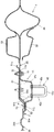
図1に示すように、本実施の形態に係る自動車1の車室内には、前後2列のシート2,3が配設されていると共に、車体側部には、フロントシート2の側方において乗降用開口4が設けられ、該開口4の後縁部に沿ってセンターピラー5が設けられている。また、センターピラー5後方の車体側部上部には、クォータウインド6が設けられ、その後方にはリヤピラー7が設けられている。また、リヤピラー7の下方には、車室側に膨出するリヤホイールハウス8が設けられていると共に、左右のリヤピラー7間の車体後壁部には、リヤゲート用開口が設けられている。
As shown in FIG. 1, two rows of front and rear seats 2, 3 are disposed in the vehicle interior of the automobile 1 according to the present embodiment, and on the side of the front seat 2 on the side of the vehicle body A boarding / alighting opening 4 is provided, and a
乗降用開口4よりも後方の車体側部は、図2にも示すように、車体外面を構成するキャブサイドアウタパネル11と、車体内面を構成する複数のパネルでなる車体内面部材12とにより構成されているが、この車体内面部材12には、クォータウインド6の下方において、車体の軽量化やサイドトリムの実装等の観点からサイドインナ開口13が設けられている。具体的には、この車体内面部材12は、前記センターピラー5上部の車体内面を構成するセンターピラーアッパインナパネル21と、センターピラー5下部の車体内面を構成するセンターピラーロアインナパネル22と、ルーフサイドレールの車体内面を構成するルーフサイドインナパネル23と、該ルーフサイドインナパネル23の後部に接合され、リヤピラー7の車体内面を構成するリヤピラーインナパネル24と、リヤピラー7の下方からその前方のセンターピラー5下部に亘って設けられ、リヤホイールハウス8周辺の車体内面及びリヤホイールハウス8の車外側の面を構成するリヤサイドインナパネル25と(図6参照)、リヤホイールハウス8の車内側の面を構成するリヤホイールハウスインナパネル26と、リヤピラー7下方のリヤゲート開口の周辺部の車内側の面を構成するリヤインナパネル27と、前記クォータウインド6の下縁に沿って前後に延び、前記センターピラーアッパインナパネル21とリヤピラーインナパネル24とを連結するベルトラインレインフォースメント28とを有している。
As shown in FIG. 2, the vehicle body side portion behind the entrance / exit 4 is configured by a cab side
ベルトラインレインフォースメント28は車体側部のベルトラインの剛性を向上させるために、前記キャブサイドアウタパネル11や他のインナパネル21〜27よりも厚くされている。
The
センターピラー9の内部には、上下に延びる断面ハット状のセンターピラーレインフォースメント31が設けられ、該センターピラーレインフォースメント31と、前記センターピラーアッパインナパネル21及びセンターピラーロアインナパネル22とで上下に延びる閉断面構造が形成されている。
A
リヤホイールハウス8の上方には、図3、図4にもあわせて示すように、リヤピラー7に取り付けられるリヤシート用シートベルトアンカSの取付部を補強し、水平断面がハット状のインナアンカレインフォースメント32及びアウタアンカレインフォースメント33がリヤサイドインナパネル25を内外から挟むように設けられ、シートベルトアンカSはアウタアンカレインフォースメント33の上部側で固定されている。
Above the
また、リヤホイールハウス8の上面と、車体後壁部におけるリヤピラー7下方のリヤゲート開口周辺部との間には、車体後部の剛性を向上させるためのリヤレインフォースメント34が架け渡されている。
A
ここで、リヤシート3のシートバック3aは、下部に設けられた回動軸3bを中心として回動可能な可倒式のものであり、図1、図2に示すように、該シートバック3aを起立状態に保持するロック装置40のラッチ41が、シートバック3aにおける車体側部側の側部に設けられ、該ラッチ41と係合するストライカ42が、リヤサイドインナパネル25におけるサイドインナ開口13の上部後方、より詳しくはベルトラインレインフォースメント28の後方下方の部位に固定されている。
Here, the seat back 3a of the rear seat 3 is a retractable type that is rotatable about a
本実施の形態においては、このストライカ42のリヤサイドインナパネル25への固定部を補強するための構造が設けられている。
In the present embodiment, a structure for reinforcing the fixing portion of the
すなわち、図3〜図6に示すように、前記リヤサイドインナパネル25におけるストライカ42が固定される部位の車外側の面に補強部材51が設けられている。この補強部材51は、リヤサイドインナパネル25に複数箇所でスポット溶接により接合されている。また、この補強部材51の周縁部には、該部材51単体としての剛性を向上させるための車外側へのフランジ状折り返し部51aが設けられている。
That is, as shown in FIGS. 3 to 6, a reinforcing
また、ベルトラインレインフォースメント28の後端部下部には、補強部材51に向かって後方下方に延びる延長部28aが設けられていると共に、補強部材51には、ベルトラインレインフォースメント28の延長部28aに向かって前方に延びる突出部51bが形成されている。そして、車外側からベルトラインレインフォースメント28の延長部28a、補強部材51の突出部51b、リヤサイドインナパネル25がこの順番で重ね合わされて(図2も参照)、αで示す複数箇所でスポット溶接により接合され、これにより、ベルトラインレインフォースメント28の延長部28aと補強部材51の突出部51bとが連結されている。また、ベルトラインレインフォースメント28の延長部28aとリヤサイドインナパネル25とはβで示す複数箇所でスポット溶接により接合されている。
In addition, an
また、ベルトラインレインフォースメント28の延長部28aには、図7にも示すように、前後に延びるビード28bが設けられている。
Further, as shown in FIG. 7, a
ストライカ42は、図3、図5、図6からよくわかるように、一対の丸棒状脚部42a,42aと、その上端同士を連結する丸棒状バー部42bとを有するゲート状の構造で、これらの脚部42a,42aがシートバック3a側のラッチ41の回動軌跡(前記回動軸3bを中心とする)上に位置するように、取付ブラケット52を介してリヤサイドインナパネル25の車内側の面に取り付けられている。
The
この取付ブラケット52は、車幅方向内側に膨出する鉢状形状とされて該鉢状形状の底部に前記ストライカ42が固定される支持部52aと、該支持部52aの反底部側からリヤサイドインナパネル25の内面に沿うように概ね上方、下方、及び後方に延びる3つの取付面部52e,52f,52g(基部)とを有し、これらの取付面部52e,52f,52gがリヤサイドインナパネル25と補強部材51との重合部にボルト61…61、ナット62…62で締結されることにより(図4も参照)、リヤサイドインナパネル25に固定されている。
The mounting
また、取付ブラケット52には、支持部52aの反底部側からリヤサイドインナパネル25の内面に沿うように前方に延びる突出部52iが設けられている。この突出部52iは、リヤサイドインナパネル25を挟んで補強部材51の突出部51bに対向するように設けられ、取付ブラケット52が固定された状態において、リヤサイドインナパネル25に当接している。また、この突出部52iには、該突出部52iを貫通する位置決め孔52jが設けられていると共に、リヤサイドインナパネル25及び補強部材51の突出部51bには位置決めピン53が溶着固定されており、この位置決めピン53と前記位置決め孔52jとを嵌合させることにより、取付ブラケット52をリヤサイドインナパネル25に対して所定位置に位置決め可能となっている。
Further, the mounting
また、取付ブラケット52の後側の取付面部52gのボルト61の挿通位置は、ストライカ42の一対の脚部42a,42aを結んだ直線の延長線L上においてこれらの脚部42a,42aの後方側に設けられていると共に、上側の取付面部52e及び下側の取付面部52fは、前記支持部52aから該延長線Lに対して直行する方向にそれぞれ設けられている。突出部52jは、該延長線L上においてこれらの脚部42a,42aの前方に設けられている。
The insertion position of the
また、リヤサイドインナパネル25には、図3、図6に示すように、取付ブラケット52の上側取付面部52eの上方及び下方において該面部52eに近接するように前後に延びるビード25a,25bが形成されている。
3 and 6, the rear side
また、図5に示すように、リヤサイドインナパネル25及び補強部材51は、ストライカ42が固定される部位において離間するように形成されており、これにより閉断面構造Yが形成されている。
Further, as shown in FIG. 5, the rear side
また、図4、図6からわかるように、補強部材51の上端部51cは、リヤサイドインナパネル25の上縁部とリヤピラーインナパネル24の下縁部との重合部、すなわち車体内面部材12として剛性の高い部位にさらに重合され、スポット溶接によりこれらが接合されている。また、図3、図6からわかるように、補強部材51の下端部後部51dはリヤサイドインナパネル25とリヤホイールハウスインナパネル26のフランジ部26aとの重合部、すなわち車体内面部材12として剛性の高い部位に重合され、スポット溶接によりこれらが接合されている。したがって、補強部材51hは、上端部51c、下端部51d、及び前端部(突出部51b)が車体内面部材12に三方で接続されることとなり、該補強部材51の車幅方向への変位が生じにくくなっている。
4 and 6, the
次に、本実施の形態の作用、効果について説明する。 Next, the operation and effect of the present embodiment will be described.
まず、前記車体内面部材12における開口部13の上方部分が、ベルトラインレインフォースメント28により構成されているので、該上方部分の剛性が向上する。また、前記車体内面部材12(リヤサイドインナパネル25)におけるストライカ42が固定される部位に補強部材51が取り付けられているので、固定部位自体の剛性も向上する。そして、前記ベルトラインレインフォースメント28が後方に延長され、該延長部28aが前記補強部材51と連結されているので、ストライカ固定部位の内側変形に対する剛性が向上することとなる。したがって、乗員着座時にストライカ42に車幅方向内向きの荷重が作用したとしても、ベルトラインレインフォースメント28に荷重が分散され、その結果、ストライカ固定部位が車幅方向内側に変位しにくくなる。
First, since the upper portion of the
そして、特に、ストライカ42がベルトラインレインフォースメント28の下方後方、すなわち開口部13の後方に設けられる場合に、該ベルトラインレインフォースメント28の延長部28aを後方下方に延長させて補強部材51と連結させたから、ベルトラインレインフォースメント全体の上下幅を大きくすることなく、車体内面部材12におけるストライカ固定部位の剛性を向上させることができる。
In particular, when the
また、前記ベルトラインレインフォースメント28の延長部28aに前後に延びるビード28bが設けられているから、該延長部28aの車幅方向に対する剛性が向上することとなる。
Further, since the
また、車体内面部材12におけるストライカ42が固定される部位からその前方側の部分が、補強部材51の突出部51bと取付ブラケット52の突出部52iとで挟まれることとなり、その結果、この挟まれた部位は、ストライカ42から内向きの荷重が作用したとしても、車幅方向外側にも内側にも変形できなくなる。したがって、車体内面部材12がストライカ42の固定部位で車幅方向内側に変位するのがより一層抑制されることとなる。
Further, a portion of the vehicle body
また、前記取付ブラケット52は、突出部52iと、車体内面部材12に取り付けられる取付面部52e,52f,52gと、ストライカ42が取り付けられ、が前記車体内面部材に対して車幅方向内側に膨出する形状とされた支持部52aとで構成されているので、比較的簡単な構造であり、しかも膨出形状により取付ブラケット52の剛性が向上することとなる。
The mounting
また、位置決め用の突出部等を別途設けると構造が複雑化するが、本実施の形態では、もともと設けてある突出部52iに、車体内面部材12の位置決めピン53とで位置決めするための位置決め孔52jが設けられているから、位置決め用の突出部等を別途形成する必要がなく、取付ブラケットの形状が複雑化するのが防止される。
Further, if a positioning protrusion or the like is separately provided, the structure becomes complicated. However, in this embodiment, a positioning hole for positioning with the
また、前記ストライカ42は、ゲート状の構造で、一対の脚部42a,42aがシートバック3a側のラッチ41の回動軌跡上に設けられた構造であるが、前記取付ブラケット52は、基部として、ストライカ42の脚部42a,42a同士を結んだ線の延長線L上で前記支持部52aに対して後方に設けられた後側取付面部52dを有しているので、ストライカ42にシートバック3a側から後ろ向きの荷重が作用したときに、その荷重を直後方で効果的に受け止めることができる。
The
また、取付ブラケット52は、基部として、前記支持部52aから前記延長線Lに対して直行する方向にそれぞれ設けられた上側取付面部52e及び下側取付面部52fを有しているが、この場合、取付ブラケット52の後側取付面部52d、特に後側取付面部52dの付け根(折曲部)には、上側取付面部52e及び下側取付面部52fの固定点を結んだ直線軸M回りに(図3参照)車外側に変位させようとする力が作用し、その結果、車体内面部材12における後側取付面部52dの付け根に接する部分が外側に変位する。一方、このように変位すると、車体内面部材12における取付ブラケット52の突出部52i側部分には、車幅方向内側へ変位しようとする力が働くが、取付ブラケット52の方が車体内面部材12よりも板厚が厚く剛性が高い素材で形成されており、変形しにくいので、車体内面部材12は、取付ブラケット52の突出部52iにより車幅方向外側に押え付けられることとなる。したがって、前記溶接箇所α、βの剥離が防止されると共に、車体内面部材12の車幅方向内側への変位が一層効果的に抑制されることとなる。
Further, the mounting
また、前記車体内面部材12(リヤサイドインナパネル25)に、前記取付ブラケット52が取り付けられる部位において、ビード25a,25bが形成されているから、該部位の車幅方向に対する剛性が向上することとなる。
Further, since the
また、前記車体内面部材12と補強部材51とで、前記取付ブラケット52が取り付けられる部位に、閉断面構造が形成されているから、該部位の剛性が向上することとなり、前述の作用・効果が一層効果的なものとなる。
In addition, since the vehicle body
ここで、本実施の形態においては、車体内面部材12における開口部13の上方部分が、ベルトラインレインフォースメント28のみにより構成されているが、この上方部分に別のインナパネルが存在しており、該インナパネルの内面あるいは外面にベルトラインレインフォースメントを設ける場合にも適用可能である。
Here, in the present embodiment, the upper part of the
本発明は、センターピラー後方の車体側部上部にクォータウインドが設けられていると共に、該クォータウインド下方の車体側部内面を構成する車体内面部材に開口部が設けられ、かつ該車体内面部材における開口部に対して上方後方の部位に、シートバックの側部に設けられたラッチと係合することにより、シートバックを起立状態にロックするストライカが固定された自動車の側部車体構造に広く適用することができる。 In the present invention, a quarter window is provided in the upper part of the vehicle body side portion behind the center pillar, and an opening is provided in the vehicle body inner surface member constituting the vehicle body side inner surface below the quarter window. Widely applied to the side body structure of automobiles in which a striker that locks the seat back in an upright state is secured by engaging with a latch provided on the side of the seat back at a position above and behind the opening. can do.
1 自動車
3a シートバック
5 センターピラー
6 クォータウィンド開口部
12 車体内面部材
13 開口部
25a ビード
28 ベルトラインレインフォースメント
28a 延長部
28b ビード
41 ラッチ
42 ストライカ
42a,42a 脚部
51 補強部材
51b 突出部(補強部材の突出部)
52 取付ブラケット
52d 後側取付面部(後側基部)
52e 上側取付面部(上側基部)
52f 下側取付面部(下側基部)
52i 突出部(取付ブラケットの突出部)
52j 位置決め部(取付ブラケットの位置決め部)
53 位置決めピン(車体内面部材側の位置決め部)
Y 閉断面構造
DESCRIPTION OF SYMBOLS 1 Automobile 3a Seat back 5
52 Mounting bracket 52d Rear mounting surface (rear base)
52e Upper mounting surface (upper base)
52f Lower mounting surface (lower base)
52i Protrusion (projection of mounting bracket)
52j Positioning part (Mounting bracket positioning part)
53 Positioning pin (Positioning part on the inner surface of the vehicle body)
Y closed section structure
Claims (7)
前記車体内面部材における開口部の上方部分が、ベルトラインレインフォースメントにより構成されていると共に、
前記車体内面部材におけるストライカが固定される部位に補強部材が取り付けられており、
かつ、前記ストライカは、前記ベルトラインレインフォースメントの下方後方において、前記シートバックを後傾姿勢の起立状態でロックするために後下がりに傾斜させて設けられていると共に、
前記ベルトラインレインフォースメントは、前記ストライカに向って後方下方に延長されて、該延長部が前記補強部材と連結されていることを特徴とする自動車の側部車体構造。 A quarter window is provided in the upper part of the vehicle body side portion behind the center pillar, and an opening is provided in the vehicle body inner surface member constituting the vehicle body side surface inner surface below the quarter window, and the upper portion of the opening in the vehicle body inner member. A side body structure of an automobile in which a striker that locks the seat back in an upright state by being engaged with a latch provided on a side portion of the seat back at a rear part,
The upper part of the opening in the inner member of the vehicle body is constituted by a belt line reinforcement,
A reinforcement member is attached to a portion where the striker is fixed in the vehicle body inner surface member,
In addition, the striker is provided at a lower rear side of the belt line reinforcement, and is inclined to be lowered rearward in order to lock the seat back in an upright posture.
The beltline reinforcement is extended rearward and downward toward the striker, and the extended portion is connected to the reinforcing member.
前記ベルトラインレインフォースメントの延長部に前後に延びるビードが設けられていることを特徴とする自動車の側部車体構造。 In the side body structure of the automobile according to claim 1,
A side body structure of an automobile, wherein a bead extending in the front-rear direction is provided at an extension of the beltline reinforcement .
前記ストライカが、車体内面部材の車内側に配設された取付ブラケットを介して前記車体内面部材に取り付けられていると共に、
前記補強部材が前記車体内面部材の車外側の面に取り付けられており、
かつ、前記補強部材には、前方に突出する突出部が設けられていると共に、
前記取付ブラケットには、前記車体内面部材を挟んで前記突出部に対向し、該車体内面部材に当接する突出部が設けられていることを特徴とする自動車の側部車体構造。 In the side part vehicle body structure of the automobile according to claim 1 or 2,
The striker is attached to the vehicle body inner surface member via a mounting bracket disposed on the vehicle inner side of the vehicle body inner surface member,
The reinforcing member is attached to a vehicle outer surface of the vehicle body inner member;
And the reinforcing member is provided with a protruding portion protruding forward,
A side body structure of an automobile, wherein the mounting bracket is provided with a protrusion that faces the protrusion and sandwiches the inner surface member of the vehicle body and contacts the inner surface member of the vehicle body .
前記取付ブラケットは、前記突出部と、車体内面部材に取り付けられる基部と、ストライカが取り付けられ、前記車体内面部材に対して車幅方向内側に膨出する支持部とを有しており、
該ブラケットの突出部に、前記車体内面部材側に設けられた位置決め部とで位置決めするための位置決め部が設けられていることを特徴とする自動車の側部車体構造。 In the side body structure of the automobile according to claim 3 ,
The mounting bracket includes the protrusion, a base attached to a vehicle body inner surface member, and a support portion to which a striker is attached and bulges inward in the vehicle width direction with respect to the vehicle body inner surface member.
A side body structure for an automobile , wherein a positioning portion for positioning with a positioning portion provided on the vehicle body inner surface member side is provided on the protruding portion of the bracket .
前記ストライカは、ゲート状の構造で、一対の脚部がシートバック側のラッチの回動軌跡上に設けられていると共に、
前記ブラケットは、基部として、前記ストライカの脚部同士を結んだ線の延長線上で前記支持部に対して後方に設けられた後側基部と、前記支持部から該延長線に対して直行する方向にそれぞれ設けられた上側基部及び下側基部とを有し、車体内面部材よりも板厚が厚く剛性が高い素材により形成されていると共に、
前記ブラケットの突出部は、前記延長線上前方に設けられていることを特徴とする自動車の側部車体構造。 In the side part body structure of the automobile according to claim 4,
The striker has a gate-like structure, and a pair of leg portions are provided on a turning locus of a latch on the seat back side,
The bracket includes, as a base portion, a rear base portion provided rearward with respect to the support portion on an extension line connecting the striker legs, and a direction perpendicular to the extension line from the support portion. And an upper base portion and a lower base portion respectively provided on the vehicle body, and is formed of a material having a thicker plate thickness and higher rigidity than the vehicle body inner surface member,
The side body structure of the automobile , wherein the protruding portion of the bracket is provided in front of the extension line .
前記車体内面部材に、前記取付ブラケットが取り付けられる部位において、ビードが形成されていることを特徴とする自動車の側部車体構造。 In the side part vehicle body structure of the automobile according to any one of claims 3 to 5 ,
A side body structure of an automobile , wherein a bead is formed at a portion where the mounting bracket is attached to the vehicle body inner surface member .
前記車体内面部材と補強部材とで、前記ストライカが固定される部位に、閉断面構造が形成されていることを特徴とする自動車の側部車体構造。 In the side part vehicle body structure of the automobile according to any one of claims 1 to 6,
A side body structure of an automobile , wherein a closed section structure is formed at a portion where the striker is fixed by the vehicle body inner surface member and the reinforcing member .
Priority Applications (1)
| Application Number | Priority Date | Filing Date | Title |
|---|---|---|---|
| JP2007086678A JP5040398B2 (en) | 2007-03-29 | 2007-03-29 | Car side body structure |
Applications Claiming Priority (1)
| Application Number | Priority Date | Filing Date | Title |
|---|---|---|---|
| JP2007086678A JP5040398B2 (en) | 2007-03-29 | 2007-03-29 | Car side body structure |
Publications (2)
| Publication Number | Publication Date |
|---|---|
| JP2008239128A JP2008239128A (en) | 2008-10-09 |
| JP5040398B2 true JP5040398B2 (en) | 2012-10-03 |
Family
ID=39910953
Family Applications (1)
| Application Number | Title | Priority Date | Filing Date |
|---|---|---|---|
| JP2007086678A Expired - Fee Related JP5040398B2 (en) | 2007-03-29 | 2007-03-29 | Car side body structure |
Country Status (1)
| Country | Link |
|---|---|
| JP (1) | JP5040398B2 (en) |
Families Citing this family (13)
| Publication number | Priority date | Publication date | Assignee | Title |
|---|---|---|---|---|
| JP2012039981A (en) * | 2010-08-23 | 2012-03-01 | Sasaki Corporation | Puddling machine |
| JP5571527B2 (en) * | 2010-10-26 | 2014-08-13 | ダイハツ工業株式会社 | Rear body structure of automobile |
| JP5698340B2 (en) * | 2011-03-10 | 2015-04-08 | 本田技研工業株式会社 | Car body rear structure |
| US9233718B2 (en) * | 2011-05-12 | 2016-01-12 | Honda Motor Co., Ltd. | Striker stiffener reinforcement |
| KR101273185B1 (en) | 2011-08-12 | 2013-06-17 | 기아자동차주식회사 | connecting structure for center filler and quarter member in vehicle without rear door |
| JP5857926B2 (en) * | 2012-09-18 | 2016-02-10 | トヨタ自動車株式会社 | Seat back striker mounting structure |
| JP6020426B2 (en) | 2013-11-27 | 2016-11-02 | トヨタ自動車株式会社 | Vehicle rear structure |
| JP6102817B2 (en) * | 2014-04-01 | 2017-03-29 | トヨタ自動車株式会社 | Vehicle rear structure |
| JP6350227B2 (en) * | 2014-11-07 | 2018-07-04 | スズキ株式会社 | Seat back holding member mounting structure |
| JP7344080B2 (en) * | 2019-10-18 | 2023-09-13 | テイ・エス テック株式会社 | side airbag device |
| CN114074717A (en) * | 2020-08-17 | 2022-02-22 | 标致雪铁龙汽车股份有限公司 | Trunk lid structure suitable for application tool |
| JP7548122B2 (en) | 2021-05-19 | 2024-09-10 | 株式会社豊田自動織機 | Rear body reinforcement structure |
| KR20220161968A (en) * | 2021-05-31 | 2022-12-07 | 현대자동차주식회사 | Structure for mounting the seat belt |
Family Cites Families (4)
| Publication number | Priority date | Publication date | Assignee | Title |
|---|---|---|---|---|
| JPH0518232Y2 (en) * | 1987-07-24 | 1993-05-14 | ||
| JPS6432281U (en) * | 1987-08-24 | 1989-02-28 | ||
| JP3307849B2 (en) * | 1997-02-10 | 2002-07-24 | ダイハツ工業株式会社 | Car body rear side structure |
| JP4556674B2 (en) * | 2005-01-13 | 2010-10-06 | マツダ株式会社 | Vehicle side body structure |
-
2007
- 2007-03-29 JP JP2007086678A patent/JP5040398B2/en not_active Expired - Fee Related
Also Published As
| Publication number | Publication date |
|---|---|
| JP2008239128A (en) | 2008-10-09 |
Similar Documents
| Publication | Publication Date | Title |
|---|---|---|
| JP5040398B2 (en) | Car side body structure | |
| US7543882B2 (en) | Dual cell rear corner pillar for automobiles | |
| JP5511310B2 (en) | Vehicle seat | |
| JP2006015928A (en) | Automobile side part structure | |
| JP5930304B2 (en) | Vehicle seat | |
| JP5002624B2 (en) | Body structure with sliding door | |
| JP2008062748A (en) | Side part body structure for vehicle | |
| JP4556674B2 (en) | Vehicle side body structure | |
| JP4682560B2 (en) | Rear body structure of the vehicle | |
| JP4332722B2 (en) | Car body rear structure | |
| JP2006137208A (en) | Rear body structure of the vehicle | |
| JP2009241779A (en) | Rear part structure of vehicle body | |
| JP4314991B2 (en) | Car body rear structure | |
| JP5339526B2 (en) | Vehicle rear body structure | |
| JP5571527B2 (en) | Rear body structure of automobile | |
| JP6645455B2 (en) | Side body structure of vehicle | |
| JP4120073B2 (en) | Lower body structure of automobile | |
| JP6057295B2 (en) | Auto body structure | |
| JP4004202B2 (en) | Truck cab | |
| JP4768168B2 (en) | Car body side structure | |
| JP2014108707A (en) | Rear seat structure of vehicle | |
| JP4058779B2 (en) | Vehicle door structure | |
| JP5528849B2 (en) | Rear seat back frame used for automobile rear seats | |
| JP2011098684A (en) | Upper vehicle body structure of vehicle | |
| JP2006213126A (en) | Body structure of automobile |
Legal Events
| Date | Code | Title | Description |
|---|---|---|---|
| RD03 | Notification of appointment of power of attorney |
Free format text: JAPANESE INTERMEDIATE CODE: A7423 Effective date: 20090618 |
|
| A621 | Written request for application examination |
Free format text: JAPANESE INTERMEDIATE CODE: A621 Effective date: 20100115 |
|
| A977 | Report on retrieval |
Free format text: JAPANESE INTERMEDIATE CODE: A971007 Effective date: 20111017 |
|
| A131 | Notification of reasons for refusal |
Free format text: JAPANESE INTERMEDIATE CODE: A131 Effective date: 20111025 |
|
| TRDD | Decision of grant or rejection written | ||
| A01 | Written decision to grant a patent or to grant a registration (utility model) |
Free format text: JAPANESE INTERMEDIATE CODE: A01 Effective date: 20120612 |
|
| A01 | Written decision to grant a patent or to grant a registration (utility model) |
Free format text: JAPANESE INTERMEDIATE CODE: A01 |
|
| A61 | First payment of annual fees (during grant procedure) |
Free format text: JAPANESE INTERMEDIATE CODE: A61 Effective date: 20120625 |
|
| R150 | Certificate of patent or registration of utility model |
Ref document number: 5040398 Country of ref document: JP Free format text: JAPANESE INTERMEDIATE CODE: R150 Free format text: JAPANESE INTERMEDIATE CODE: R150 |
|
| FPAY | Renewal fee payment (event date is renewal date of database) |
Free format text: PAYMENT UNTIL: 20150720 Year of fee payment: 3 |
|
| LAPS | Cancellation because of no payment of annual fees |