JP5032055B2 - Cleaning device - Google Patents
Cleaning device Download PDFInfo
- Publication number
- JP5032055B2 JP5032055B2 JP2006122104A JP2006122104A JP5032055B2 JP 5032055 B2 JP5032055 B2 JP 5032055B2 JP 2006122104 A JP2006122104 A JP 2006122104A JP 2006122104 A JP2006122104 A JP 2006122104A JP 5032055 B2 JP5032055 B2 JP 5032055B2
- Authority
- JP
- Japan
- Prior art keywords
- cleaning
- belt
- shaped transfer
- width direction
- transfer body
- Prior art date
- Legal status (The legal status is an assumption and is not a legal conclusion. Google has not performed a legal analysis and makes no representation as to the accuracy of the status listed.)
- Expired - Fee Related
Links
Images


Classifications
-
- G—PHYSICS
- G03—PHOTOGRAPHY; CINEMATOGRAPHY; ANALOGOUS TECHNIQUES USING WAVES OTHER THAN OPTICAL WAVES; ELECTROGRAPHY; HOLOGRAPHY
- G03G—ELECTROGRAPHY; ELECTROPHOTOGRAPHY; MAGNETOGRAPHY
- G03G15/00—Apparatus for electrographic processes using a charge pattern
- G03G15/14—Apparatus for electrographic processes using a charge pattern for transferring a pattern to a second base
- G03G15/16—Apparatus for electrographic processes using a charge pattern for transferring a pattern to a second base of a toner pattern, e.g. a powder pattern, e.g. magnetic transfer
- G03G15/1605—Apparatus for electrographic processes using a charge pattern for transferring a pattern to a second base of a toner pattern, e.g. a powder pattern, e.g. magnetic transfer using at least one intermediate support
- G03G15/161—Apparatus for electrographic processes using a charge pattern for transferring a pattern to a second base of a toner pattern, e.g. a powder pattern, e.g. magnetic transfer using at least one intermediate support with means for handling the intermediate support, e.g. heating, cleaning, coating with a transfer agent
Landscapes
- Physics & Mathematics (AREA)
- General Physics & Mathematics (AREA)
- Electrostatic Charge, Transfer And Separation In Electrography (AREA)
- Control Or Security For Electrophotography (AREA)
Description
本発明は、クリーニング装置に関し、さらに詳しくは、転写行程に用いられるベルトを対象としたクリーニング機構に関する。 The present invention relates to cleaning equipment, and more particularly, to a cleaning mechanism intended for belt used in the transfer process.
複写機やファクシミリ装置あるいはプリンタや印刷機等の画像形成装置においては、潜像担持体である感光体に形成された静電潜像をトナーにより可視像処理し、可視像が転写されて担持されている記録用紙やOHPフィルムなどのシート状記録媒体(以下、記録シートという)を定着装置に供して定着することにより
複写物や印刷出力を得るようになっている。
In an image forming apparatus such as a copying machine, a facsimile machine, a printer, or a printing machine, an electrostatic latent image formed on a photosensitive member, which is a latent image carrier, is processed with a visible image, and the visible image is transferred. A sheet-like recording medium (hereinafter referred to as a recording sheet) such as a recording paper or an OHP film that is carried is used for fixing to a fixing device to obtain a copy or a printed output.
感光体に形成される画像は、モノクロ画像のみでなく、フルカラー画像が対象となる場合もある。
フルカラー画像を形成する場合の転写工程では、複数の感光体を並置した作像部に対して記録シートを移動させる課程で各色の画像を順次転写する構成の他に、ベルトなどの中間転写体を用いて1次転写を行い、1次転写により得られた重畳画像を記録シートに対して一括転写する2次転写を行う構成がある(例えば、特許文献1)。
The image formed on the photoconductor may be a full-color image as well as a monochrome image.
In the transfer process when forming a full-color image, in addition to the configuration in which the image of each color is sequentially transferred in the process of moving the recording sheet to the image forming unit in which a plurality of photoconductors are juxtaposed, an intermediate transfer member such as a belt is used. There is a configuration in which primary transfer is performed and secondary transfer is performed in which a superimposed image obtained by the primary transfer is collectively transferred to a recording sheet (for example, Patent Document 1).
中間転写体は記録シートなどに重畳画像を一括転写した後、残留するトナーや紙粉を除去するためのクリーニングが実行される。 The intermediate transfer member collectively transfers the superimposed image onto a recording sheet or the like, and then cleaning is performed to remove residual toner and paper dust.
クリーニングのための構成には、中間転写体に接触するブレードやブラシローラを用いる構成が知られている(例えば、特許文献2)。 As a configuration for cleaning, a configuration using a blade or a brush roller in contact with an intermediate transfer member is known (for example, Patent Document 2).
ところで、中間転写体として用いられるベルトに残留するトナーや紙粉は、特許文献2に開示されているように、ベルトの幅方向端部側に付着しやすいことが知られている。このため、中間転写体のクリーニングに際しては、少なくともベルトの幅方向端部にクリーニング部材を設け、端部近傍のベルト表面に付着しているトナーや紙粉を掻き取ったり、あるいは幅方向に沿って移動するベルト状のクリーニング部材を用いてトナーや紙粉を拭き取る構成が用いられることがある。
Incidentally, it is known that the toner and paper dust remaining on the belt used as the intermediate transfer member are likely to adhere to the end in the width direction of the belt, as disclosed in
しかし、ベルトの幅方向端部近傍の表面に付着しているトナーや紙粉を除去する場合には次のような問題を発生することがある。
図10は、中間転写体として用いられるベルトAの幅方向を含む幅方向全域を対象としてクリーニングブレードBやクリーニングブラシCを接触させる構成がを示している。
この構成においては、中間転写ベルトにおける画像形成範囲を対象としてクリーニングブレードBによりベルト上に残っているトナーTを堰き止めることにより、あるいは、あるいはクリーニングブラシCの摺擦によってそれぞれ掻き取るようにしている。
However, when the toner or paper dust adhering to the surface in the vicinity of the end in the width direction of the belt is removed, the following problems may occur.
FIG. 10 shows a configuration in which the cleaning blade B and the cleaning brush C are brought into contact with the entire width direction including the width direction of the belt A used as an intermediate transfer member.
In this configuration, the toner T remaining on the belt is dammed by the cleaning blade B for the image forming range on the intermediate transfer belt, or is scraped off by the rubbing of the cleaning brush C. .
しかし、ブレードにより堰き止められたトナーTが堆積するとベルトの移動によりトナーTが押し動かされてブレードBの幅方向端部に向けて移動することがあり、この結果、図10中、矢印で示すように、クリーニングブレードAあるいはクリーニングブラシBの端部から零れて漏れ出すことになる。 However, when the toner T blocked by the blade accumulates, the toner T may be pushed by the movement of the belt and move toward the end in the width direction of the blade B. As a result, the toner T is indicated by an arrow in FIG. In this way, the cleaning blade A or the cleaning brush B spills out and leaks out.
クリーニング部材の端部から漏れ出たトナーは周辺部に飛散し周辺に配置されている機器の汚損や機構部品の摩耗などを引き起こす虞があり、さらには、ベルトに付着したままであると、ベルト表面に薄膜状に残るトナーフィルミングを招き、中間転写体としての帯電特性の悪化や固着によるクリーニング部材の損傷を招くこともある。 Toner that leaks from the end of the cleaning member may scatter to the periphery and cause damage to equipment disposed in the periphery, wear of mechanical parts, and the like. Toner filming remaining on the surface as a thin film may be caused, and the charging characteristics as an intermediate transfer member may be deteriorated or the cleaning member may be damaged due to fixation.
そこで、端部専用として新たな回収部材(図10中、符号Dで示す部材)を設けることや、この部分にシール部材を配置することも考えられるが、回収部材の端部からの漏れ出しを完全に防ぐことができず、また、シール部材を気密的に設けると内部圧の異常な上昇により噴出する虞もあるばかりでなく、部材の追加や構成の複雑化を招くことになる。 Therefore, it is conceivable to provide a new recovery member exclusively for the end portion (a member indicated by symbol D in FIG. 10) or to arrange a seal member in this portion, but leakage from the end portion of the recovery member It cannot be completely prevented, and if the seal member is provided in an airtight manner, there is a risk that the internal pressure may be ejected due to an abnormal increase in internal pressure, and the addition of members and the complication of the configuration will be caused.
本発明の目的は、上記従来のクリーニング装置における問題に鑑み、構成の複雑化を招くことなくトナーの漏れ出しを確実に防止してトナーの飛散による汚損や部品の損傷を防止することができる構成を備えたクリーニング装置および画像形成装置を提供することにある。 In view of the above problems in the conventional cleaning device, an object of the present invention is to reliably prevent leakage of toner without causing complication of the configuration and prevent contamination and damage to parts due to toner scattering. The present invention provides a cleaning device and an image forming apparatus including the above.
本発明は、上記目的を達成するために次の構成よりなる。
(1)潜像担持体に形成された可視像を転写されるベルト状転写体に残存するトナーを清掃するクリーニング装置であって、
上記ベルト状転写体が転写終了後に移動する位置に設けられている第1のクリーニング部と、
上記第1のクリーニング部とは別に、上記ベルト状転写体の移動方向において上記第1のクリーニングよりも上流側に配置され、上記ベルト状転写体の移動方向と直角な方向に相当する幅方向の各端部において該ベルト状転写体を挟んで対向するクリーニング部材及びこのクリーニング部材にベルト状転写体を押し当てるための固定部材を備えた第2のクリーニング部とを備え、
上記第2のクリーニングに設けられたクリーニング部材及び固定部材は、上記ベルト状転写体の移動に対して不動状態を維持され、クリーニング部材は、上記ベルト状転写体の幅方向に沿った傾斜面を有し、堰き止めたトナーをベルト状転写体の幅方向に移動させ、該幅方向に移動したトナーが上記第1のクリーニング部において回収されることを特徴とするクリーニング装置。
(2)上記クリーニング部材及び固定部材における少なくともクリーニング部材には上記ベルト状転写体と接触する面にブラシ材が備えられていることを特徴とする請求項1記載のクリーニング装置。
(3)上記クリーニング部材の傾斜面は、上記ベルト状転写体の移動方向に対して堰き止められたトナーを該ベルト状転写体の幅方向外側から幅方向中央側に向けて移動させる傾斜方向が設定されていることを特徴とする請求項1又は2記載のクリーニング装置。
(4)上記クリーニング部材の傾斜面は、上記ベルト状転写体の移動方向に対して堰き止められたトナーを該ベルト状転写体の幅方向中央側から幅方向外側に向けて移動させる傾斜方向が設定されていることを特徴とする請求項1又は2記載のクリーニング装置。
(5)上記クリーニング部材は、上記ベルト状転写体の幅方向における画像形成領域の外側において該領域から所定間隔を持たせた位置に配置されていることを特徴とする請求項1乃至4のうちの一つに記載のクリーニング装置。
(6)潜像担持体に形成された可視像を転写されるベルト状転写体に残存するトナーを清掃するクリーニング装置であって、
上記ベルト状転写体が転写終了後に移動する位置に設けられている第1のクリーニング部と、
上記第1のクリーニング部とは別に、上記ベルト状転写体の移動方向と直角な方向に相当する幅方向の各端部において該ベルト状転写体を挟んで対向するクリーニング部材及びこのクリーニング部材にベルト状転写体を押し当てるための固定部材を備えた第2のクリーニング部とを備え、
上記第2のクリーニングに設けられたクリーニング部材及び固定部材は、上記ベルト状転写体の移動に対して不動状態を維持され、上記固定部材には、上記ベルト状転写体の移動速度を検知する検知手段が一体的に設けられていることを特徴とするクリーニング装置。
The present invention has the following configuration in order to achieve the above object.
(1) A cleaning device for cleaning toner remaining on a belt-like transfer body to which a visible image formed on a latent image carrier is transferred,
A first cleaning unit provided at a position where the belt-shaped transfer body moves after the transfer is completed;
Aside from the first cleaning section, the belt-shaped transfer member is disposed upstream of the first cleaning in the moving direction of the belt-shaped transfer member, and has a width direction corresponding to a direction perpendicular to the moving direction of the belt-shaped transfer member. A cleaning member that is opposed to each other with the belt-shaped transfer member sandwiched at each end, and a second cleaning unit that includes a fixing member for pressing the belt-shaped transfer member against the cleaning member;
The cleaning member and the fixing member provided in the second cleaning are kept stationary with respect to the movement of the belt-shaped transfer body, and the cleaning member has an inclined surface along the width direction of the belt-shaped transfer body. A cleaning device, wherein the toner that has been dammed is moved in the width direction of the belt-like transfer member, and the toner moved in the width direction is collected in the first cleaning section .
(2) The cleaning device according to
(3) The inclined surface of the cleaning member has an inclination direction for moving the toner blocked with respect to the moving direction of the belt-shaped transfer body from the outer side in the width direction of the belt-shaped transfer body toward the center in the width direction. The cleaning device according to
(4) The inclined surface of the cleaning member has an inclination direction for moving the toner blocked with respect to the moving direction of the belt-shaped transfer body from the center in the width direction to the outer side in the width direction of the belt-shaped transfer body. The cleaning device according to
(5) The cleaning member is disposed outside the image forming region in the width direction of the belt-shaped transfer member at a position spaced apart from the region. The cleaning device according to one of the above.
(6) A cleaning device for cleaning toner remaining on a belt-like transfer body to which a visible image formed on a latent image carrier is transferred,
A first cleaning unit provided at a position where the belt-shaped transfer body moves after the transfer is completed;
In addition to the first cleaning unit, a cleaning member that faces the belt-like transfer member at each end in the width direction corresponding to a direction perpendicular to the moving direction of the belt-like transfer member, and a belt attached to the cleaning member A second cleaning unit provided with a fixing member for pressing the shaped transfer body,
The cleaning member and the fixing member provided for the second cleaning are kept stationary with respect to the movement of the belt-shaped transfer member, and the fixing member detects the moving speed of the belt-shaped transfer member. A cleaning device characterized in that the means are provided integrally.
本発明によれば、ベルト状転写体の幅方向端部に配置したクリーニング部材をベルト状転写体に接触させる構成とするだけでベルト状転写体に残存するトナーがその端部から漏れ出すのを防止しながら回収除去することができる。これにより、端部から漏れ出すトナーによる汚損や部材の破損を防止することができる。 According to the present invention, the toner remaining on the belt-shaped transfer body can be prevented from leaking from the end portion only by having the cleaning member disposed at the widthwise end of the belt-shaped transfer body in contact with the belt-shaped transfer body. It can be recovered and removed while preventing. As a result, it is possible to prevent the toner leaking from the end portion and the member from being damaged.
特に、本発明では、ベルト状転写体の移動に対して不動状態を維持する第2のクリーニング部において、堰き止められたトナーがベルト状転写体の幅方向に移動されるので、ベルト状転写体に残存するトナーがその端部から漏れ出すのを良好に防止することができる。 In particular , in the present invention, since the dammed toner is moved in the width direction of the belt-shaped transfer body in the second cleaning unit that maintains a stationary state with respect to the movement of the belt-shaped transfer body, the belt-shaped transfer body It is possible to satisfactorily prevent the toner remaining in the toner from leaking from the end portion.
以下、図面により本発明を実施するための最良の形態について説明する。 The best mode for carrying out the present invention will be described below with reference to the drawings.
図1は、本発明によるクリーニング装置が適用される画像形成装置1の構成を示す図である。
図1に示す画像形成装置1は、色分解に対応した色の画像を形成可能な潜像担持体としての感光体を複数並置したタンデム方式の構成を備え、各感光体上で形成されたトナー像を中間転写体に重畳転写したうえでその重畳画像を記録用紙などのシートに対して一括転写することで多色画像を形成可能なカラープリンタである。本発明では、画像形成装置として、カラープリンタに限らず、カラー複写機、ファクシミリ装置および印刷機なども含まれること勿論である。
FIG. 1 is a diagram showing a configuration of an
An
図1において、カラープリンタ1は、画像形成部1Aが縦方向の中央部に位置し、その下方には給紙部1Bが、さらに画像形成部1Aの上方には原稿載置台1C1を備えた原稿走査部1Cがそれぞれ配置されている。
画像形成部1Aには、水平方向に展張面を有する中間転写体として中間転写ベルト2で構成された転写手段が配置されており、中間転写ベルト2の上位には、色分解色と補色関係にある色の画像を形成するための構成が設けられている。
In FIG. 1, in a
In the image forming unit 1A, a transfer unit composed of an
画像形成部1Aには、補色関係にある色のトナー(イエロー、マゼンタ、シアン、ブラック)による画像を担持可能な感光体3B、3Y、3C、3Mが中間転写体2の展張面に沿って並置されている。なお、以下の説明において、全ての感光体に共通する内容の場合には感光体を符号3により示す。
各感光体3B、3Y、3C、3Mは、それぞれ同じ方向(図1では、反時計方向)に回転可能なドラムで構成されており、その周辺には、回転過程において画像形成処理を実行する帯電装置4,書き込み装置5,現像装置6,転写バイアス印加手段の一つである1次転写装置7,およびクリーニング装置8が配置されている(便宜上、感光体3Bを対象として、各装置の符号にBを付して示してある)。
In the image forming unit 1A,
Each of the
中間転写ベルト2は、各感光体を備えた作像ユニットからの可視像を順次転写される1次転写部に相当しており、複数のローラ2A〜2Cに掛け回されて感光体との対峙位置において同方向に移動可能な構成を備え、展張面を構成するローラ2A、2Bとは別のローラ2Cは、中間転写ベルト2を挟んで2次転写装置9に対峙している。
The
2次転写装置9は、帯電駆動ローラ9Aおよび従動ローラ9Bに掛け回されて2次転写装置9が位置する2次転写位置において中間転写ベルト2と同方向に移動可能な転写ベルト9Cを備えており、転写ベルト9Cを帯電駆動ローラ9Aにより帯電させることで記録シートを静電吸着しながら搬送する過程で中間転写ベルト2に重畳された多色画像を一括転写によってあるいは担持されている単一色の画像をそれぞれ記録シートに転写することができる。
The
2次転写位置には給紙部1Bから記録シートが給送されるようになっている。
給紙部1Bは、複数の給紙カセット1B1と、給紙カセット1B1から繰り出される記録シートの搬送路に配置された複数の搬送ローラ1B2と、2次転写位置前方に位置するレジストローラ1B3とを備えている。本実施例では、給紙部1Bには、給紙トレイ1B1から繰り出される記録シートの搬送路に加えて給紙カセット1B1内に収容されていない種類の記録シートを2次転写位置に向け給送できる構成が備えられており、この構成は、画像形成部1Aの壁面の一部を起倒可能に設けた手差しトレイ1A1と繰り出しコロ1A2とを備えている。
給紙カセット1B1からレジストローラ1B3に向けた記録シートの搬送路途中には、手差しトレイ1A1から繰り出された記録シートの搬送路が合流し、いずれの搬送路から給送される記録シートもレジストローラ1B3によってレジストタイミングが設定されるようになっている。
A recording sheet is fed from the paper feeding unit 1B to the secondary transfer position.
The paper feed unit 1B includes a plurality of paper feed cassettes 1B1, a plurality of transport rollers 1B2 arranged in a transport path for recording sheets fed from the paper feed cassette 1B1, and a registration roller 1B3 positioned in front of the secondary transfer position. I have. In this embodiment, in addition to the conveyance path of the recording sheet fed out from the sheet feeding tray 1B1, a recording sheet of a type not stored in the sheet feeding cassette 1B1 is fed to the sheet feeding unit 1B toward the secondary transfer position. This configuration includes a manual feed tray 1A1 and a feeding roller 1A2 provided with a part of the wall surface of the image forming unit 1A that can be turned up and down.
In the middle of the conveyance path of the recording sheet from the sheet feeding cassette 1B1 to the registration roller 1B3, the conveyance path of the recording sheet fed out from the manual feed tray 1A1 joins, and the recording sheet fed from any conveyance path is also a registration roller. Registration timing is set by 1B3.
書き込み装置5(図1では、便宜上、黒画像形成のための書込光を符号5Bで示してある)は、原稿走査部1Cに有する原稿載置台1C1上の原稿を走査することにより得られる画像情報あるいは図示しないコンピュータから出力される画像情報により書き込み光が制御されて感光体3B、3Y、3C、3Mに対して画像情報に応じた静電潜像を形成するようになっている。
The writing device 5 (in FIG. 1, the writing light for forming a black image is indicated by reference numeral 5B for the sake of convenience) is an image obtained by scanning the document on the document table 1C1 in the
原稿走査部1Cには、原稿載置台1C1上の原稿を露光走査するスキャナ1C2が備えられており、さらに原稿載置台1C1の上面には、自動原稿給送装置1C3が配置されている。自動原稿給送装置1C3は、原稿載置台1C1上に繰り出される原稿を反転可能な構成を備え、原稿の表裏各面での走査が行えるようになっている。
The
書き込み装置5により形成された感光体3(図1において符号3B、3Y、3C、3Mで示す部材)上の静電潜像は、現像装置6(図1では、便宜上、符号6Bで示してある)によって可視像処理され、中間転写ベルト2に1次転写される。中間転写ベルト2に対して各色毎のトナー像が重畳転写されると、2次転写装置9により記録シートに対して一括して2次転写される。
An electrostatic latent image formed on the photoconductor 3 (members indicated by
2次転写された記録シートは、表面に担持している未定着画像を定着装置11によって定着される。定着装置11は、詳細を図示しないが加熱ローラにより加熱される定着ベルトと定着ベルトに対向当接する加圧ローラとを備えたベルト定着構造を備えており、定着ベルトと加圧ローラとの当接領域、つまりニップ領域を設けることにより別ローラ方式の定着構造に比べて記録シートへの加熱領域を広げることができるようになっている。
定着装置11を通過した記録シートは、定着装置11の後方に配置されている搬送路切り換え爪12によって搬送方向が切り換えられるようになっており、排紙トレイ13に向けた搬送路と、反転搬送路RPとに搬送方向が選択される。
The unfixed image carried on the surface of the recording sheet that has been secondarily transferred is fixed by the fixing device 11. Although not shown in detail, the fixing device 11 includes a belt fixing structure including a fixing belt heated by a heating roller and a pressure roller facing and abutting the fixing belt, and the contact between the fixing belt and the pressure roller. By providing the area, that is, the nip area, the heating area for the recording sheet can be expanded as compared with the fixing structure of another roller type.
The recording sheet that has passed through the fixing device 11 is switched in the transport direction by a transport path switching claw 12 disposed behind the fixing device 11, and is transported toward the
以上のような構成を備えたカラープリンタ1では、原稿載置台1C1上に載置された原稿を露光走査することによりあるいはコンピュータからの画像情報により、一様帯電された感光体3に対して静電潜像が形成され、静電潜像が現像装置6によって可視像処理された後、トナー像が中間転写ベルト2に1次転写される。
In the
中間転写ベルト2に転写されたトナー像は、単一色画像の場合にはそのまま給紙部1Bから繰り出された記録シートに対して転写され、多色画像の場合には1次転写が繰り返されることで重畳された上で記録シートに対して一括して2次転写される。2次転写後の記録シートは定着装置11により未定着画像を定着された後、排紙トレイ13あるいは、反転されて再度レジストローラ1B3に向けて給送される。
The toner image transferred to the
図1において、中間転写ベルト2は、詳細を図示しないが、伸びの少ないフッ素系樹脂や伸びの大きいゴム材料に帆布等の伸びにくい材料で構成された基部からなるベース層と、このベース層の上面に設けられたフッ素系ゴムやアクリロニトリル−ブタジェン共重合ゴムなどが用いられる弾性体層とを備えている。弾性体層の表面にはフッ素系樹脂が被覆されて平滑性を向上させたコート層が設けられている。
In FIG. 1, although not shown in detail, the
中間転写ベルト2は、少なくとも一対のローラである支持ローラ2A、2Bおよびバックアップ機能を有するローラ2Cにそれぞれ掛け回されて駆動ローラ2Aの反時計方向の回転によって駆動されるようになっている。
支持ローラ2Aおよび2B間で展張される面、つまり曲率のない平面が各作像ユニットの感光体3B、3Y、3C、3Mに対向している。中間転写ベルト2を挟んで各感光体と対向する位置には、感光体上の可視像を静電転写するための転写ローラ2Dがそれぞれ配置されている。
The
A surface extended between the
本発明によるクリーニング装置は、中間転写ベルト2を対象として設けられており、図1おいて符号10で示すように、中間転写ベルト2の移動方向において各作像位置に至る前の位置に設けられている第1のクリーニング部と、これとは別に、中間転写ベルト2の幅方向端部を対象としてクリーニングを行う第2のクリーニング部100とで構成されている。
The cleaning device according to the present invention is provided for the
第2のクリーニング部100は、第1のクリーニング部であるクリーニング装置10が配置されているローラ2Aと対向する位置から外れた位置でクリーニング装置10よりも中間転写ベルト2の移動方向上流側に位置している。
The
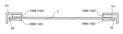
図2は、第2のクリーニング部の構成を示す中間転写ベルト2の幅方向に沿った横断面図であり、同図において、第2のクリーニング部は、中間転写ベルト2の移動方向と直角な方向に相当する幅方向の各端部近傍において中間転写ベルト2を挟んで対向するクリーニング部材100Aと固定部材100Bとで構成されている。なお、図2において符号20は、中間転写ベルト2の蛇行を防止するための係止凸部を示しており、この係止凸部20がローラの軸方向端縁に衝合することでベルト2の蛇行を防止できるようになっている。
FIG. 2 is a transverse sectional view along the width direction of the
クリーニング部材100Aは、図3および図4に示すように、装置内の不動部に設けられている支持部材101によって中間転写ベルト2に対向する面と反対側の面が支持された発泡材100A1と、中間転写ベルト2に対面する位置に設けられたブラシ材100A2とで構成されている。
本実施形態では、発泡材として、発泡ポリウレタン等のスポンジ材や発泡ゴム材が用いられ、中間転写ベルト2に圧接した際にベルト表面に食い込ませてトナーを堰き止めることができるようになっている。
As shown in FIGS. 3 and 4, the cleaning
In this embodiment, a sponge material such as foamed polyurethane or a foam rubber material is used as the foam material, and when pressed against the
ブラシ材100A2は、ナイロン、レーヨンなどの材料を電着植毛することで構成されており、中間転写ベルト2の表面に圧接してトナー堰き止める際にベルト表面での摩擦によるベルトが削られてしまうことや不用意な摩耗を防止するようになっている。
The brush material 100A2 is configured by electrodepositing a material such as nylon or rayon, and the belt due to friction on the belt surface is scraped when pressed against the surface of the
固定部材100Bは、図示しない不動部に設けられた本体100B1と中間転写ベルト2と対向する面に設けられたブラシ材100B2とで構成されている。
The fixing
固定部材100Bの本体100B1は、比較的硬度のある樹脂あるいは金属が用いられ、ブラシ材100B2は、クリーニング部材100A側に有するものと同様な材質が用いられている。
The main body 100B1 of the fixing
固定部材100Bは、中間転写ベルト2とクリーニング部材100Aとの接触圧力を均一に保つための部材であり、中間転写ベルト2の波打などを防止してクリーニング部材100Aに対する中間転写ベルト2の位置関係を一定に保つようになっている。
なお、固定部材100Bは、不動状態に設けるだけでなく、中間転写ベルト2に対するクリーニング部材100A側の当接圧力によって上下方向に弾性変形する構成とすることも可能であり、この構成によりクリーニング部材100A側で設定される中間転写ベルト2に対する位置関係により発生する当接圧力を一定に維持するようにしてもよい。
The fixing
The fixing
クリーニング部材100Aは、堰き止めたトナーを中間転写ベルト2の幅方向に移動させることができる構成とされている。
The cleaning
図5は、このための構成を示しており、同図においてクリーニング部材100Aは、中間転写ベルト2の幅方向に対して傾斜した面100A3を有している。
FIG. 5 shows a configuration for this purpose. In FIG. 5, the cleaning
傾斜面100A3は、中間転写ベルト2の移動方向(図示矢印方向)の上流側に位置しており、端部側に位置するトナーTを中間転写ベルト2の幅方向中央に向け移動させることができる形態とされている。特に、図5においては、中間転写ベルト2の移動方向および幅方向に沿った辺が直角に設けられた三角形の斜辺が中間転写ベルト2の移動方向上流側から下流側に向けて傾斜する形態とされている。
The inclined surface 100A3 is located on the upstream side in the moving direction (arrow direction shown) of the
このような傾斜面100A3を有することにより、画像形成範囲内にトナーが移動することになり、移動したトナーがクリーニング装置10に設けてあるブレード(図5においては、便宜上、符号10で示してある)などによって掻き取られることになり、結果として、端部側から漏れ出そうとするトナーをなくすことができる。
By having such an inclined surface 100A3, the toner moves within the image forming range, and the moved toner is indicated by
一方、クリーニング部材100Aは、中間転写ベルト2における画像形成範囲に対する位置を次の関係とされている。
図5において、クリーニング部材100Aは、中間転写ベルト2における画像形成範囲の両端から所定量を超えた位置に配置されており、具体的には、クリーニング部材100Aの内側端部の位置が画像形成範囲の端部から2mm以上離れた位置とされ、さらに、この内側端部が第1のクリーニング部に位置するブレード10の長手方向端部を超えた位置にされている。
On the other hand, the position of the cleaning
In FIG. 5, the cleaning
画像形成範囲に対するクリーニング部材100Aの配置位置を規定する理由は、図6に示す実験結果に基づく。
図6は、画像形成範囲端部とクリーニング部材100Aの配置位置との関係によるトナー汚損の発生具合を実験した結果であり、繰り返し回数を10回として実験したところ、2mm以上とした場合にトナー汚損が少ない高評価値(標準値を4とする)を得ることができた。このように、上述した配置関係とすることで、トナーが端部に回り込んで漏れ出すことが殆どなく、クリーニング部材100Aにより端部から幅方向中央側に移動させることでクリーニング装置のブレードによる掻き取りが良好に行えることでトナー汚損を低減されることが判る。
The reason for defining the arrangement position of the cleaning
FIG. 6 shows the result of an experiment on the degree of toner contamination caused by the relationship between the end of the image forming range and the position where the cleaning
本実施形態においては、端部側から漏れ出そうとするトナーがクリーニング部材100A1により堰き止めるだけでなく、端部から中央に向けて移動されて端部側から離れるようにされるので、掻き取り部材と同様な機能を有するクリーニング部材に多機能を持たせて構成が煩雑化するのを防止することができる。 In this embodiment, the toner that is about to leak from the end side is not only blocked by the cleaning member 100A1, but is also moved from the end portion toward the center so as to be separated from the end side. The cleaning member having the same function as the member can be provided with multiple functions to prevent the configuration from becoming complicated.
次、本実施形態の要部変形例を説明する。
図7は、クリーニング部材100Aにより堰き止められたトナーを中間転写ベルト2の幅方向に移動させる構成の他の例として、クリーニング部材100Aの傾斜面100A3の傾斜方向を図5に示した場合と逆方向に設定した場合を示している。
この構成においては、中間転写ベルト2の幅方向外側に向けてトナーが移動することになるので、端部近傍にトナー回収部102を設けて飛散しようとするトナーを除去する。この構成は、例えば、図5に示した場合のようなクリーニング部材100Aと画像形成範囲との位置関係が設定できないような場合に用いる。
Next, a modification of the main part of the present embodiment will be described.
FIG. 7 shows, as another example of the configuration in which the toner blocked by the cleaning
In this configuration, since the toner moves toward the outer side in the width direction of the
次に本発明の別の実施形態について説明する。
図8に示す実施形態は、中間転写ベルト2に形成されたエンコードマーク(スケール)Pを検出してベルトの移動速度をフィードバック制御するために用いられ検知手段の一部に第2のクリーニング部が組み込まれていることを特徴としている。このようなスケールを用いた速度制御に関しては、本出願人が先に出願した特開平11−24507号公報などに開示されている。
Next, another embodiment of the present invention will be described.
The embodiment shown in FIG. 8 is used for detecting an encode mark (scale) P formed on the
図8は、図4相当の横断面図であり、同図において第1のクリーニング部1000は、中間転写ベルト2を挟んで対向する位置に配置されているクリーニング部材1000Aと、固定部材1000Bとで構成されている。
クリーニング部材1000Aは、図5に示した場合と同様に、発泡材1000A1とブラシ材1000A2とで構成されている。
一方、固定部材1000Bは、エンコードマークPからの反射光を利用する光学センサで構成された検知部材1001を取り付ける部材として兼用されており、具体的には、図9に示すように、光透過用の開口1000B3を有する支持基板1000B1とこれの中間転写ベルト2側の面に設けてあるブラシ材1000B2とで構成されている。
FIG. 8 is a cross-sectional view corresponding to FIG. 4. In FIG. 8, the first cleaning unit 1000 includes a cleaning
The cleaning
On the other hand, the fixing
支持基板1000B1には、図8に示すように、検知部材1001が一体的に取り付けられている。なお、図9は、支持基板1000B1の構成を示すために検知部材1001を便宜上、支持基板1000B1から分解した状態で示してあるが、通常は、図8に示すように支持基板1000B1と一体化されて用いられる。
固定部材1000Bに用いられる支持基板1000B1は、図示しないが、装置側の不動部において不動状態で支持されている。
As shown in FIG. 8, the
Although not shown, the support substrate 1000B1 used for the fixing
本実施形態においては、検知部材10001の支持構造をクリーニング部として用いることができるので、部品点数および構成の簡略化が可能となる。しかも、エンコードマークPと検知部材1001との間の光学的光路長が変化しない除隊に維持されることになるので、検知部材1001によるスケール読み取り精度を高めることができ、さらには、この付近で飛散しようとする端部からの漏れ出しトナーを除去できるので、検知部材1001での汚損も防止して検知精度の悪化を回避することができる。
In the present embodiment, since the support structure for the detection member 10001 can be used as a cleaning unit, the number of components and the configuration can be simplified. In addition, since the optical path length between the encode mark P and the
1 画像形成装置
2 中間転写ベルト
10 第1のクリーニング部であるクリーニング装置
100 第2のクリーニング部
100A、1000A クリーニング部材
100B、1000B 固定部材
100A2,1000A2,100B2,1000B2 ブラシ材
1000B3 開口
1001 検知部材
DESCRIPTION OF
Claims (6)
上記ベルト状転写体が転写終了後に移動する位置に設けられている第1のクリーニング部と、
上記第1のクリーニング部とは別に、上記ベルト状転写体の移動方向において上記第1のクリーニングよりも上流側に配置され、上記ベルト状転写体の移動方向と直角な方向に相当する幅方向の各端部において該ベルト状転写体を挟んで対向するクリーニング部材及びこのクリーニング部材にベルト状転写体を押し当てるための固定部材を備えた第2のクリーニング部とを備え、
上記第2のクリーニングに設けられたクリーニング部材及び固定部材は、上記ベルト状転写体の移動に対して不動状態を維持され、クリーニング部材は、上記ベルト状転写体の幅方向に沿った傾斜面を有し、堰き止めたトナーをベルト状転写体の幅方向に移動させ、該幅方向に移動したトナーが上記第1のクリーニング部において回収されることを特徴とするクリーニング装置。 A cleaning device for cleaning toner remaining on a belt-like transfer body to which a visible image formed on a latent image carrier is transferred,
A first cleaning unit provided at a position where the belt-shaped transfer body moves after the transfer is completed;
Aside from the first cleaning section, the belt-shaped transfer member is disposed upstream of the first cleaning in the moving direction of the belt-shaped transfer member, and has a width direction corresponding to a direction perpendicular to the moving direction of the belt-shaped transfer member. A cleaning member that is opposed to each other with the belt-shaped transfer member sandwiched at each end, and a second cleaning unit that includes a fixing member for pressing the belt-shaped transfer member against the cleaning member;
The cleaning member and the fixing member provided in the second cleaning are kept stationary with respect to the movement of the belt-shaped transfer body, and the cleaning member has an inclined surface along the width direction of the belt-shaped transfer body. A cleaning device, wherein the toner that has been dammed is moved in the width direction of the belt-like transfer member, and the toner moved in the width direction is collected in the first cleaning section .
上記ベルト状転写体が転写終了後に移動する位置に設けられている第1のクリーニング部と、
上記第1のクリーニング部とは別に、上記ベルト状転写体の移動方向と直角な方向に相当する幅方向の各端部において該ベルト状転写体を挟んで対向するクリーニング部材及びこのクリーニング部材にベルト状転写体を押し当てるための固定部材を備えた第2のクリーニング部とを備え、
上記第2のクリーニングに設けられたクリーニング部材及び固定部材は、上記ベルト状転写体の移動に対して不動状態を維持され、上記固定部材には、上記ベルト状転写体の移動速度を検知する検知手段が一体的に設けられていることを特徴とするクリーニング装置。 A cleaning device for cleaning toner remaining on a belt-like transfer body to which a visible image formed on a latent image carrier is transferred,
A first cleaning unit provided at a position where the belt-shaped transfer body moves after the transfer is completed;
In addition to the first cleaning unit, a cleaning member that faces the belt-like transfer member at each end in the width direction corresponding to a direction perpendicular to the moving direction of the belt-like transfer member, and a belt attached to the cleaning member A second cleaning unit provided with a fixing member for pressing the shaped transfer body,
The cleaning member and the fixing member provided for the second cleaning are kept stationary with respect to the movement of the belt-shaped transfer member, and the fixing member detects the moving speed of the belt-shaped transfer member. A cleaning device characterized in that the means are provided integrally.
Priority Applications (2)
| Application Number | Priority Date | Filing Date | Title |
|---|---|---|---|
| JP2006122104A JP5032055B2 (en) | 2006-04-26 | 2006-04-26 | Cleaning device |
| US11/740,570 US7764918B2 (en) | 2006-04-26 | 2007-04-26 | Cleaning device and image forming apparatus |
Applications Claiming Priority (1)
| Application Number | Priority Date | Filing Date | Title |
|---|---|---|---|
| JP2006122104A JP5032055B2 (en) | 2006-04-26 | 2006-04-26 | Cleaning device |
Publications (2)
| Publication Number | Publication Date |
|---|---|
| JP2007293109A JP2007293109A (en) | 2007-11-08 |
| JP5032055B2 true JP5032055B2 (en) | 2012-09-26 |
Family
ID=38763787
Family Applications (1)
| Application Number | Title | Priority Date | Filing Date |
|---|---|---|---|
| JP2006122104A Expired - Fee Related JP5032055B2 (en) | 2006-04-26 | 2006-04-26 | Cleaning device |
Country Status (2)
| Country | Link |
|---|---|
| US (1) | US7764918B2 (en) |
| JP (1) | JP5032055B2 (en) |
Families Citing this family (5)
| Publication number | Priority date | Publication date | Assignee | Title |
|---|---|---|---|---|
| JP2009217238A (en) * | 2008-02-15 | 2009-09-24 | Seiko Epson Corp | Transfer device and image forming apparatus |
| JP5136782B2 (en) * | 2008-06-10 | 2013-02-06 | コニカミノルタビジネステクノロジーズ株式会社 | Intermediate transfer belt and image forming apparatus |
| JP2012022077A (en) * | 2010-07-13 | 2012-02-02 | Fuji Xerox Co Ltd | Cleaning device and image forming apparatus having the device |
| JP6217335B2 (en) * | 2013-11-14 | 2017-10-25 | コニカミノルタ株式会社 | Image forming apparatus |
| JP6347648B2 (en) * | 2014-04-07 | 2018-06-27 | キヤノン株式会社 | Image forming apparatus |
Family Cites Families (25)
| Publication number | Priority date | Publication date | Assignee | Title |
|---|---|---|---|---|
| JPH03102385A (en) * | 1989-09-18 | 1991-04-26 | Minolta Camera Co Ltd | Cleaning device |
| JP3268061B2 (en) | 1993-05-20 | 2002-03-25 | 株式会社リコー | Image recording device |
| JPH08278707A (en) * | 1995-02-10 | 1996-10-22 | Ricoh Co Ltd | Image forming device and method thereof |
| JP3516551B2 (en) | 1995-05-11 | 2004-04-05 | 株式会社リコー | Electrostatic image forming device |
| US5784674A (en) * | 1995-06-29 | 1998-07-21 | Fuji Xerox Co., Ltd. | Inner face cleaning member for an intermediate transfer device |
| JP3429112B2 (en) * | 1995-08-18 | 2003-07-22 | 株式会社リコー | Color electrophotographic equipment |
| US5983060A (en) | 1997-03-31 | 1999-11-09 | Ricoh Company, Ltd. | Image forming apparatus which removes a surface potential of an intermediate transfer member |
| JPH1124507A (en) | 1997-07-07 | 1999-01-29 | Ricoh Co Ltd | Image forming device |
| JP3676932B2 (en) | 1998-11-24 | 2005-07-27 | 株式会社リコー | Transfer method and image forming apparatus |
| JP2001318541A (en) | 2000-05-12 | 2001-11-16 | Casio Electronics Co Ltd | Image forming device |
| US6374073B2 (en) * | 2000-06-28 | 2002-04-16 | Kyocera Mita Corporation | Image forming machine |
| JP3963638B2 (en) | 2000-09-07 | 2007-08-22 | 株式会社リコー | Image forming apparatus |
| JP2002278308A (en) * | 2001-03-19 | 2002-09-27 | Ricoh Co Ltd | Cleaning device for image forming device |
| EP1271259B1 (en) | 2001-06-26 | 2013-11-20 | Ricoh Company, Ltd. | Image forming apparatus and process cartridge therefor |
| JP2003029541A (en) | 2001-07-13 | 2003-01-31 | Ricoh Co Ltd | Image forming device |
| JP4004020B2 (en) | 2001-07-23 | 2007-11-07 | 株式会社リコー | Bias application method, bias application device, and image forming apparatus |
| JP2003131497A (en) | 2001-10-29 | 2003-05-09 | Ricoh Co Ltd | Tranfer device and image forming device using the same |
| US6711368B2 (en) * | 2001-12-12 | 2004-03-23 | Kabushiki Kaisha Toshiba | Image forming apparatus designed to prevent curling of a cleaning blade |
| US6842602B2 (en) * | 2002-03-22 | 2005-01-11 | Ricoh Company, Ltd. | Drive control device and image forming apparatus including the same |
| JP2004061888A (en) | 2002-07-29 | 2004-02-26 | Ricoh Co Ltd | Image forming apparatus |
| JP2004109469A (en) | 2002-09-18 | 2004-04-08 | Ricoh Co Ltd | Image forming apparatus |
| US20050232667A1 (en) * | 2004-04-15 | 2005-10-20 | Canon Kabushiki Kaisha | Image forming apparatus having image bearing member and toner removal means |
| JP4590992B2 (en) | 2004-09-08 | 2010-12-01 | コニカミノルタビジネステクノロジーズ株式会社 | Image forming apparatus |
| JP4455978B2 (en) | 2004-11-15 | 2010-04-21 | 株式会社リコー | Mark detection device, drive control device, belt drive device, and image forming device |
| US7233761B2 (en) | 2005-07-13 | 2007-06-19 | Ricoh Company, Ltd. | Method and apparatus for transferring multiple toner images and image forming apparatus |
-
2006
- 2006-04-26 JP JP2006122104A patent/JP5032055B2/en not_active Expired - Fee Related
-
2007
- 2007-04-26 US US11/740,570 patent/US7764918B2/en active Active
Also Published As
| Publication number | Publication date |
|---|---|
| US7764918B2 (en) | 2010-07-27 |
| US20070286654A1 (en) | 2007-12-13 |
| JP2007293109A (en) | 2007-11-08 |
Similar Documents
| Publication | Publication Date | Title |
|---|---|---|
| JP5352992B2 (en) | Image forming apparatus | |
| JP4777172B2 (en) | Image forming apparatus | |
| JP2007011083A (en) | Fixing device and image forming apparatus | |
| JP2008152307A (en) | Image forming apparatus | |
| JP5032055B2 (en) | Cleaning device | |
| JP5570233B2 (en) | Image forming apparatus | |
| JP4497856B2 (en) | Image forming apparatus | |
| JP6237379B2 (en) | Fixing apparatus and image forming apparatus | |
| JP4307404B2 (en) | Image forming apparatus | |
| JP2013029769A (en) | Image forming device | |
| CN102331700B (en) | Cleaning device, the image processing system comprising this cleaning device and clean method | |
| JP2007041582A (en) | Image forming apparatus | |
| JP2006343773A (en) | Belt device and image forming apparatus using the same | |
| JP2009014956A (en) | Image forming apparatus | |
| JP4457876B2 (en) | Image forming apparatus | |
| JP3521685B2 (en) | Image forming device | |
| JP4920936B2 (en) | Image forming apparatus | |
| JP5311768B2 (en) | Image forming apparatus | |
| JP4180908B2 (en) | Image forming apparatus | |
| JP2008122876A (en) | Cleaning device and image forming apparatus | |
| JP2004109635A (en) | Image forming apparatus | |
| JP7494601B2 (en) | Image forming device | |
| JP2005215553A (en) | Belt device, transfer device, and image forming apparatus | |
| JP5464797B2 (en) | Image forming apparatus | |
| JP5377722B2 (en) | Image forming apparatus |
Legal Events
| Date | Code | Title | Description |
|---|---|---|---|
| A621 | Written request for application examination |
Free format text: JAPANESE INTERMEDIATE CODE: A621 Effective date: 20090219 |
|
| A131 | Notification of reasons for refusal |
Free format text: JAPANESE INTERMEDIATE CODE: A131 Effective date: 20110823 |
|
| A521 | Written amendment |
Free format text: JAPANESE INTERMEDIATE CODE: A523 Effective date: 20111006 |
|
| A131 | Notification of reasons for refusal |
Free format text: JAPANESE INTERMEDIATE CODE: A131 Effective date: 20120228 |
|
| A521 | Written amendment |
Free format text: JAPANESE INTERMEDIATE CODE: A523 Effective date: 20120418 |
|
| TRDD | Decision of grant or rejection written | ||
| A01 | Written decision to grant a patent or to grant a registration (utility model) |
Free format text: JAPANESE INTERMEDIATE CODE: A01 Effective date: 20120626 |
|
| A01 | Written decision to grant a patent or to grant a registration (utility model) |
Free format text: JAPANESE INTERMEDIATE CODE: A01 |
|
| A61 | First payment of annual fees (during grant procedure) |
Free format text: JAPANESE INTERMEDIATE CODE: A61 Effective date: 20120628 |
|
| R150 | Certificate of patent or registration of utility model |
Ref document number: 5032055 Country of ref document: JP Free format text: JAPANESE INTERMEDIATE CODE: R150 Free format text: JAPANESE INTERMEDIATE CODE: R150 |
|
| FPAY | Renewal fee payment (event date is renewal date of database) |
Free format text: PAYMENT UNTIL: 20150706 Year of fee payment: 3 |
|
| LAPS | Cancellation because of no payment of annual fees |