JP5025258B2 - Rotating electrical machine rotor - Google Patents
Rotating electrical machine rotor Download PDFInfo
- Publication number
- JP5025258B2 JP5025258B2 JP2006352868A JP2006352868A JP5025258B2 JP 5025258 B2 JP5025258 B2 JP 5025258B2 JP 2006352868 A JP2006352868 A JP 2006352868A JP 2006352868 A JP2006352868 A JP 2006352868A JP 5025258 B2 JP5025258 B2 JP 5025258B2
- Authority
- JP
- Japan
- Prior art keywords
- rotor core
- rotor
- permanent magnet
- outer peripheral
- peripheral portion
- Prior art date
- Legal status (The legal status is an assumption and is not a legal conclusion. Google has not performed a legal analysis and makes no representation as to the accuracy of the status listed.)
- Expired - Fee Related
Links
Images


Landscapes
- Permanent Field Magnets Of Synchronous Machinery (AREA)
Description
本発明は、ロータハブの外周面にロータコアのハブ挿入孔を圧入することで前記ロータハブに前記ロータコアを固定し、前記ロータコアの外周面に沿って所定間隔で設けた複数の永久磁石支持孔にそれぞれ永久磁石を挿入して固定した回転電機のロータに関する。 According to the present invention, the rotor core is fixed to the rotor hub by press-fitting a hub insertion hole of the rotor core into the outer peripheral surface of the rotor hub, and each of the permanent magnet support holes provided at predetermined intervals along the outer peripheral surface of the rotor core is permanently provided. The present invention relates to a rotor of a rotating electrical machine in which a magnet is inserted and fixed.
ロータシャフトにスプライン結合されたロータコアの外周部に複数のスロットを形成し、それらのスロットにそれぞれ永久磁石を挿入した回転電機のロータにおいて、隣接するスロット間のブリッジ部に曲げ荷重を受ける形状のリブを形成することで、永久磁石に作用する遠心力でスロットの径方向外側の隅部の応力が集中するのを回避するものが、下記特許文献1により公知である。 In a rotor of a rotating electrical machine in which a plurality of slots are formed on the outer periphery of a rotor core splined to the rotor shaft, and permanent magnets are inserted into the slots, a rib having a shape that receives a bending load at a bridge portion between adjacent slots It is known from Japanese Patent Application Laid-Open No. 2002-151820 that the stress at the corners on the radially outer side of the slot is concentrated due to the centrifugal force acting on the permanent magnet.
またロータ鉄心の外周部に複数の永久磁石を固定した回転子をエンジンのクランクシャフトの端面および変速機の入力軸の端面にボルトやリベットのような締結部材で固定した電動機において、永久磁石の径方向内側のロータ鉄心に複数の肉抜き部を形成したものが下記特許文献2により公知である。
ところで、この種の回転電機のロータにおいて、ロータハブにロータコアを圧入し、かつロータコアに形成した永久磁石支持孔に永久磁石を挿入すると、前記圧入荷重によってロータコアの外周部が円周方向に引き伸ばされて永久磁石支持孔の径方向外側の隅部に強い引張応力が集中してしまい、しかもロータの回転に伴って永久磁石に遠心力が加わると、その遠心力がロータコアの外周部を円周方向に引き伸ばすように作用するため、前記引張応力が更に高くなってロータコアの耐久性に悪影響を及ぼす可能性がある。 By the way, in a rotor of this type of rotating electrical machine, when a rotor core is press-fitted into a rotor hub and a permanent magnet is inserted into a permanent magnet support hole formed in the rotor core, the outer peripheral portion of the rotor core is stretched in the circumferential direction by the press-fitting load. If strong tensile stress is concentrated at the corners on the radially outer side of the permanent magnet support hole, and centrifugal force is applied to the permanent magnet as the rotor rotates, the centrifugal force causes the outer periphery of the rotor core to move in the circumferential direction. Since it acts to stretch, the tensile stress may be further increased, which may adversely affect the durability of the rotor core.
本発明は前述の事情に鑑みてなされたもので、ロータコアの永久磁石支持孔の径方向外側の隅部における応力集中を緩和してロータコアの耐久性を高めることを目的とする。 The present invention has been made in view of the above circumstances, and an object of the present invention is to alleviate stress concentration at the radially outer corners of the permanent magnet support holes of the rotor core and improve the durability of the rotor core.
上記目的を達成するために、請求項1に記載された発明によれば、ロータハブの外周面に、ロータコアの内周部に設けたハブ挿入孔を圧入することで、前記ロータハブに前記ロータコアを固定し、前記ロータコアの外周部に、該ロータコアの外周面に沿って所定間隔で複数の永久磁石支持孔を設けると共に、それら永久磁石支持孔にそれぞれ永久磁石を挿入して固定した回転電機のロータであって、前記ロータコアは、それの前記内周部および前記外周部の中間において、円周方向に沿って配置される複数の肉抜き孔と、その各肉抜き孔を挟むように円周方向に沿って配置されて該ロータコアの前記内周部および前記外周部間を連結する複数のリブとを備え、各々の前記複数のリブは、前記ロータコアの前記内周部に連結されるリブ一端部が所定の前記永久磁石の内周側に位置し且つ前記ロータコアの前記外周部に連結されるリブ他端部が前記所定の永久磁石と円周方向で隣り合う他の永久磁石の内周側に位置するように配置されていて、該リブの中間部に2つの湾曲部を有しており、前記ロータハブの外周面に前記ロータコアのハブ挿入孔を圧入する際に前記永久磁石支持孔の隅部に生じる応力を、前記複数のリブの前記湾曲部の変形により緩和することを特徴とする回転電機のロータが提案される。 To achieve the above object, according to the invention described in claim 1, the outer peripheral surface of the rotor hub, by press-fitting the hub insertion hole formed in the inner peripheral portion of the rotor core, fixed to the rotor core in the rotor hub and, the outer peripheral portion of the rotor core, with along the outer peripheral surface of the rotor core provide a multiple permanent magnet support hole at predetermined intervals, the rotary electric machine is fixed by inserting the permanent magnets each of which the permanent magnet support hole rotor a is, the rotor core is Oite between inside of the inner peripheral portion and the outer peripheral portion of it, and a plurality of lightening holes which are arranged along the circumferential direction, so as to sandwich the respective lightening holes are arranged along the circumferential direction and a plurality of ribs connecting between the inner circumferential portion and the outer peripheral portion of the rotor core, each of said plurality of ribs are connected to the inner peripheral portion of the rotor core One end of the rib The other end of the rib located on the inner circumference side of the fixed permanent magnet and connected to the outer circumference portion of the rotor core is located on the inner circumference side of another permanent magnet adjacent to the predetermined permanent magnet in the circumferential direction. And has two curved portions at the intermediate portion of the rib, and when the hub insertion hole of the rotor core is press-fitted into the outer peripheral surface of the rotor hub, the corner is formed at the corner of the permanent magnet support hole. A rotor of a rotating electrical machine is proposed in which the generated stress is relieved by deformation of the curved portions of the plurality of ribs.
また請求項2に記載された発明によれば、請求項1の構成に加えて、前記ロータコアの外周面に、隣接する永久磁石支持孔間に延びるV字状の切欠きを形成したことを特徴とする回転電機のロータが提案される。
According to the invention described in
請求項1の構成によれば、ロータハブの外周面にロータコアのハブ挿入孔を圧入すると、ロータコアの外周部が円周方向に引き伸ばされて永久磁石支持孔の径方向外側の隅部に引張応力が集中し、しかもロータが回転するとロータコアの外周部および永久磁石に作用する遠心力によって前記引張応力が更に強まってしまう。しかしながら、ロータコアの内周部および外周部の中間において、円周方向に沿って配置される複数の肉抜き孔と、その各肉抜き孔を挟むように円周方向に沿って配置されて該ロータコアの内周部および外周部間を連結する複数のリブとを備えたので、前記圧入により発生する前記隅部の応力集中をリブの変形により緩和してロータコアの耐久性を高めることができ、これにより磁気的に高性能であるが疲労強度が高くない材料や、安価であるが疲労強度が高くない材料でロータコアを製作することができる。 According to the first aspect of the present invention, when the hub insertion hole of the rotor core is press-fitted into the outer peripheral surface of the rotor hub, the outer peripheral portion of the rotor core is stretched in the circumferential direction and tensile stress is applied to the radially outer corner of the permanent magnet support hole. When the rotor is concentrated and the rotor rotates, the tensile stress is further increased by the centrifugal force acting on the outer peripheral portion of the rotor core and the permanent magnet. However, Oite between in the inner circumferential portion and the outer circumferential portion of the rotor core, a plurality of lightening holes which are arranged along the circumferential direction, are arranged along the circumferential direction so as to sandwich the respective lightening holes The plurality of ribs connecting the inner and outer peripheral portions of the rotor core are provided , so that the stress concentration at the corners caused by the press-fitting is alleviated by the deformation of the ribs, thereby improving the durability of the rotor core. Thus, the rotor core can be manufactured from a material that is magnetically high performance but does not have high fatigue strength, or that is inexpensive but does not have high fatigue strength.
また、各々の複数のリブを、ロータコアの内周部に連結されるリブ一端部が所定の永久磁石の内周側に位置し且つロータコアの外周部に連結されるリブ他端部が前記所定の永久磁石と円周方向で隣り合う他の永久磁石の内周側に位置するように配置し、且つ該リブの中間部に2つの湾曲部を有するようにして、ロータハブの外周面にロータコアのハブ挿入孔を圧入する際に永久磁石支持孔の隅部に生じる応力を、複数のリブの前記湾曲部の変形により緩和させたので、ロータハブの外周面にロータコアのハブ挿入孔を圧入する際の荷重で前記リブを容易に変形させ、前記圧入による引張応力が永久磁石支持孔の径方向外側の隅部に集中するのを一層効果的に抑制することができる。 Also, each of the plurality of ribs, the ribs and the other end portion of the rib end portion connected to the inner peripheral portion of the rotor core are connected to the outer peripheral portion of the position is and the rotor core on the inner peripheral side of a given permanent magnet is predetermined The permanent magnet is positioned so as to be located on the inner peripheral side of another permanent magnet that is adjacent to the permanent magnet in the circumferential direction, and has two curved portions at the intermediate portion of the rib, so that the rotor core is disposed on the outer peripheral surface of the rotor hub. The stress generated in the corners of the permanent magnet support hole when the hub insertion hole is press-fitted is alleviated by the deformation of the curved portions of the plurality of ribs, so that when the hub core insertion hole of the rotor core is press-fitted into the outer peripheral surface of the rotor hub The rib can be easily deformed by a load, and the tensile stress due to the press-fitting can be more effectively suppressed from concentrating on the radially outer corner of the permanent magnet support hole.
また請求項2の構成によれば、ロータコアの外周面に、隣接する永久磁石支持孔間に延びるV字状の切欠きを形成したので、該永久磁石と隣接する他の永久磁石との間での磁気短絡を防止して磁気効率を高めることができる。前記切欠きを形成すると永久磁石支持孔の径方向外側の隅部に応力が集中し易くなるが、ロータコアの肉抜き孔およびリブによる応力緩和効果により、前記応力集中を許容範囲内に納めることができる。 According to the second aspect of the present invention, the V-shaped notch extending between the adjacent permanent magnet support holes is formed on the outer peripheral surface of the rotor core, so that the permanent magnet is adjacent to the other permanent magnet. The magnetic efficiency can be increased by preventing the magnetic short circuit. When the notch is formed, stress tends to concentrate on the radially outer corner of the permanent magnet support hole, but the stress concentration can be kept within an allowable range due to the stress relaxation effect by the hollow hole and rib of the rotor core. it can.
以下、本発明の実施の形態を添付の図面に基づいて説明する。 Hereinafter, embodiments of the present invention will be described with reference to the accompanying drawings.
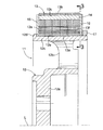
図1〜図5は本発明の実施の形態を示すもので、図1はロータの斜視図、図2は図1の2−2線拡大断面図(図3の2−2線断面図)、図3は図2の3−3線矢視図、図4は永久磁石支持孔の隅部に加わる応力の時間変化を示すグラフ、図5は永久磁石支持孔の隅部に加わる平均応力および応力振幅を示すグラフである。 1 to 5 show an embodiment of the present invention, FIG. 1 is a perspective view of a rotor, FIG. 2 is an enlarged sectional view taken along line 2-2 in FIG. 1 (cross sectional view taken along line 2-2 in FIG. 3), 3 is a view taken along line 3-3 in FIG. 2, FIG. 4 is a graph showing a time change of stress applied to the corner of the permanent magnet support hole, and FIG. 5 is average stress and stress applied to the corner of the permanent magnet support hole. It is a graph which shows an amplitude.
図1および図2に示すように、モータのステータの内部に軸線Lまわりに回転自在に配置されるロータ11は、ロータハブ12と、ロータコア13と、複数の永久磁石14…と、第1端板15と、第2端板16と、リテーナ17とで構成される。
As shown in FIGS. 1 and 2, the
ロータハブ12は、ハブ本体部12aと、ハブ本体部12aから放射方向に延びる複数個のスポーク部12b…と、スポーク部12b…の先端を一体に連結する環状のロータコア支持部12cとを備えており、ロータコア支持部12cの軸線L方向一端面から径方向外向きにフランジ12dが突出する。ロータハブ12のロータコア支持部12cの外周面12eに、環状のロータコア13のハブ挿入孔13aが圧入により固定される。ロータコア13は複数の鋼板を積層したもので、その外周面13bに沿うように等間隔で複数の永久磁石支持孔13c…が形成される。各々の永久磁石支持孔13cは断面長方形をなしてロータコア13の軸線L方向両端面に開口しており、そこに直方体状の永久磁石14が挿入されて接着等により固定される。
The
図3を併せて参照すると明らかなように、ロータコア13の外周面13bから隣接する永久磁石支持孔13c…間にV字状の切欠き13d…が延びており、この切欠き13d…により永久磁石14…の間での磁気短絡を防止し、磁束をトルク発生のために効率良く利用することができる。
As apparent from FIG. 3, a V-
ロータコア13の内周部および外周部の中間において、円周方向に沿って環状に配置された複数の肉抜き孔13e…が形成される。これらの肉抜き孔13e…は各々がS字状に湾曲した形状を有しており、内周部および外周部間を連結する複数のリブ13f…により相互に仕切られている。また、各々のリブ13fは、ロータコア13の内周部に連結されるリブ一端部が所定の永久磁石14の内周側に位置し且つロータコア13の外周部に連結されるリブ他端部が前記所定の永久磁石14と円周方向で隣り合う他の永久磁石14の内周側に位置するように配置されて、該リブ13fの中間部に2つの湾曲部を有するように形成されている。
In the middle of the inner peripheral portion and the outer peripheral portion of the
尚、永久磁石支持孔13c…と肉抜き孔13e…とに挟まれた部分(バックヨーク)は磁路としての役割を果たす部分であるため、そのバックヨークの厚さTは永久磁石14…の幅Wの0.5〜0.7倍程度が必要になる。
Since the portion (back yoke) sandwiched between the permanent
図2から明らかなように、ロータハブ12の外周面12eに、第1端板15と、ロータコア13のハブ挿入孔13aと、第2端板16と、リテーナ17とを圧入することで、ロータハブ12のフランジ12dとリテーナ17との間に第1端板15、ロータコア13および第2端板16が挟まれて軸線L方向に移動不能に固定される。
As apparent from FIG. 2, the
次に、上記構成を備えた本発明の実施の形態の作用を説明する。 Next, the operation of the embodiment of the present invention having the above configuration will be described.
ロータハブ12のロータコア支持部12cの外周面12eにロータコア13のハブ挿入孔13aを圧入すると、環状のロータコア13が円周方向に引き伸ばされることで引張応力が発生する。本実施の形態の如く、ロータコア13の直径に対するロータハブ12の直径の比率が高い場合、つまりロータハブ12の直径が大きい場合には、前記引張応力は大きなものとなる。そして、図3に示す永久磁石支持孔13c…の径方向外側の隅部13g…は、前記V字状の切欠き13d…を形成したことで細幅になっているために、特に大きな引張応力が作用する。
When the
またロータ11が回転するとロータコア13自体も遠心力で径方向外向きに付勢されるため、ロータコア13の外周部が円周方向に引き伸ばされて隅部13g…の引張応力は更に高くなる。しかもロータ11が回転すると遠心力で永久磁石14…が径方向外向きに付勢されるため、永久磁石14…から伝達される荷重で隅部13g…の引張応力は更に高くなり、ロータコア13の耐久性を低下させる可能性がある。
Further, when the
しかしながら、本実施の形態では、ロータコア13の内周部および外周部の中間において、円周方向に沿って配置される複数の肉抜き孔13eと、その各肉抜き孔13eを挟むように円周方向に沿って配置されて該ロータコア13の内周部および外周部間を連結する複数のリブ13f…とを備え、各々のリブ13fは、ロータコア13の内周部に連結されるリブ一端部が所定の永久磁石14の内周側に位置し且つロータコア13の外周部に連結されるリブ他端部が前記所定の永久磁石14と円周方向で隣り合う他の永久磁石14の内周側に位置するように配置されて、該リブ13fの中間部に2つの湾曲部を有するので、ロータコア13のハブ挿入孔13aにロータハブ12の外周面12eを圧入することで発生する円周方向の引張荷重をリブ13f…の変形により吸収し、その引張荷重がロータコア13の外周部に伝達され難くすることができる。これにより、永久磁石支持孔13c…の隅部13g…の応力集中を緩和し、ロータコア13の耐久性を高めることができる。特に、リブ13f…は中間部に2つの湾曲部を有するようにしてS字状に湾曲しているため、円周方向の引張荷重で容易に変形して該引張荷重の伝達を確実に抑制することができる。
However, in this embodiment, Oite between in the inner circumferential portion and the outer circumferential portion of the
図4のグラフは、ロータ11が回転および停止を繰り返したときの永久磁石支持孔13c…の隅部13g…の応力の変化を示すもので、実線は本実施の形態のロータ11に対応し、破線は肉抜き孔13e…およびリブ13f…を持たない従来のロータに対応している。
The graph of FIG. 4 shows the change in stress at the
ロータ11が回転すると遠心力による応力が発生し、ロータ11が停止すると遠心力による応力が消滅するために所定の振幅では応力が増減するが、この遠心力による応力振幅Δσは実施の形態のものと従来のものとで同じである。しかしながら、実施の形態のロータハブ12は圧入による応力σaが従来例の応力σa′よりも大幅に減少するため、実施の形態の平均応力σbは従来例の平均応力σb′よりも大幅に減少する。
When the
図5のグラフは、平均応力および応力振幅に基づくロータコア13の疲労限度を示すもので、実線は本実施の形態のロータ11に対応し、破線は肉抜き孔13e…およびリブ13f…を持たない従来のロータに対応している。
The graph of FIG. 5 shows the fatigue limit of the
実施の形態のロータコア13は圧入による応力の減少により平均応力が低くなるため、廉価材を使用しても必要な耐久性を満たすことが可能であるが、従来例のロータコア13は圧入による応力の減少が見込めないために平均応力が高くなり、高価な高強度材を使用しないと必要な耐久性を満たすことが困難になる。
The
しかして、本実施の形態のロータコア13は、磁気的に高性能であるが疲労強度が高くない材料や、安価であるが疲労強度が高くない材料を使用した場合でも、永久磁石支持孔13c…の隅部13g…の応力集中を緩和して耐久性を確保することができる。
Thus, the
以上、本発明の実施の形態を詳述したが、本発明はその要旨を逸脱しない範囲で種々の設計変更を行うことが可能である。 As mentioned above, although embodiment of this invention was explained in full detail, this invention can perform a various design change in the range which does not deviate from the summary.
例えば、実施の形態ではモータのロータ11を例示したが、本発明は発電機のロータに対しても適用することができる。
For example, although the
12 ロータハブ
12e 外周面
13 ロータコア
13a ハブ挿入孔
13b 外周面
13c 永久磁石支持孔
13d 切欠き
13e 肉抜き孔
13f リブ
13g 隅部
14 永久磁石
12
Claims (2)
前記ロータコア(13)は、それの前記内周部および前記外周部の中間において、円周方向に沿って配置される複数の肉抜き孔(13e)と、その各肉抜き孔(13e)を挟むように円周方向に沿って配置されて該ロータコア(13)の前記内周部および前記外周部間を連結する複数のリブ(13f)とを備え、
各々の前記複数のリブ(13f)は、前記ロータコア(13)の前記内周部に連結されるリブ一端部が所定の前記永久磁石(14)の内周側に位置し且つ前記ロータコア(13)の前記外周部に連結されるリブ他端部が前記所定の永久磁石(14)と円周方向で隣り合う他の永久磁石(14)の内周側に位置するように配置されていて、該リブ(13f)の中間部に2つの湾曲部を有しており、
前記ロータハブ(12)の外周面(12e)に前記ロータコア(13)のハブ挿入孔(13a)を圧入する際に前記永久磁石支持孔(13c)の隅部(13g)に生じる応力を、前記複数のリブ(13f)の前記湾曲部の変形により緩和することを特徴とする回転電機のロータ。 The outer peripheral surface of the rotor hub (12) (12e), by press-fitting the hub insertion hole formed in the inner peripheral portion of the rotor core (13) (13a) fixed to the rotor core (13) wherein the rotor hub (12), the outer periphery of the rotor core (13), provided with a multiple of the permanent magnet support hole (13c) at predetermined intervals along the outer peripheral surface (13b) of said rotor core (13), in which the permanent magnet support hole (13c) A rotor of a rotating electrical machine in which a permanent magnet (14) is inserted and fixed,
Said rotor core (13), Oite between inside of the inner peripheral portion and the outer peripheral portion thereof, a plurality of lightening holes which are arranged along the circumferential direction (13e), each of its lightening holes (13e And a plurality of ribs (13f) that are arranged along the circumferential direction so as to sandwich the inner peripheral portion of the rotor core (13) and connect the inner peripheral portion and the outer peripheral portion .
In each of the plurality of ribs (13f), one end of the rib connected to the inner peripheral portion of the rotor core (13) is located on the inner peripheral side of the predetermined permanent magnet (14), and the rotor core (13) The other end of the rib connected to the outer peripheral portion is disposed so as to be located on the inner peripheral side of the other permanent magnet (14) circumferentially adjacent to the predetermined permanent magnet (14), It has two curved parts in the middle part of the rib (13f),
The stress generated in the corner portion (13 g) of the permanent magnet support hole (13c) when press-fitting the hub insertion hole (13a) of the the outer circumferential surface (12e) rotor core (13) of said rotor hub (12), said plurality A rotor of a rotating electrical machine that is relaxed by deformation of the curved portion of the rib (13f).
Priority Applications (1)
| Application Number | Priority Date | Filing Date | Title |
|---|---|---|---|
| JP2006352868A JP5025258B2 (en) | 2006-12-27 | 2006-12-27 | Rotating electrical machine rotor |
Applications Claiming Priority (1)
| Application Number | Priority Date | Filing Date | Title |
|---|---|---|---|
| JP2006352868A JP5025258B2 (en) | 2006-12-27 | 2006-12-27 | Rotating electrical machine rotor |
Publications (2)
| Publication Number | Publication Date |
|---|---|
| JP2008167549A JP2008167549A (en) | 2008-07-17 |
| JP5025258B2 true JP5025258B2 (en) | 2012-09-12 |
Family
ID=39696258
Family Applications (1)
| Application Number | Title | Priority Date | Filing Date |
|---|---|---|---|
| JP2006352868A Expired - Fee Related JP5025258B2 (en) | 2006-12-27 | 2006-12-27 | Rotating electrical machine rotor |
Country Status (1)
| Country | Link |
|---|---|
| JP (1) | JP5025258B2 (en) |
Cited By (1)
| Publication number | Priority date | Publication date | Assignee | Title |
|---|---|---|---|---|
| US11303172B2 (en) | 2018-03-09 | 2022-04-12 | Nissan Motor Co., Ltd. | Rotor for rotating electrical machine and rotor core support structure for rotating electrical machine |
Families Citing this family (3)
| Publication number | Priority date | Publication date | Assignee | Title |
|---|---|---|---|---|
| JP5990475B2 (en) * | 2013-02-14 | 2016-09-14 | 本田技研工業株式会社 | Rotating electrical machine rotor |
| CN107947446B (en) * | 2017-12-29 | 2024-06-25 | 沈阳蓝光驱动技术有限公司 | Rotor shaft gravity center offset type inner rotor permanent magnet motor |
| WO2019189599A1 (en) * | 2018-03-30 | 2019-10-03 | 日本電産株式会社 | Rotor, motor, and electric power steering device |
Family Cites Families (3)
| Publication number | Priority date | Publication date | Assignee | Title |
|---|---|---|---|---|
| JP3654806B2 (en) * | 1999-12-27 | 2005-06-02 | 松下電器産業株式会社 | Electric motor permanent magnet rotor and hermetic compressor using the same |
| JP2005051826A (en) * | 2003-06-02 | 2005-02-24 | Honda Motor Co Ltd | Fixed structure of permanent magnet in rotor of rotating electric machine |
| JP4283081B2 (en) * | 2003-10-08 | 2009-06-24 | 本田技研工業株式会社 | Rotating electrical machine rotor |
-
2006
- 2006-12-27 JP JP2006352868A patent/JP5025258B2/en not_active Expired - Fee Related
Cited By (1)
| Publication number | Priority date | Publication date | Assignee | Title |
|---|---|---|---|---|
| US11303172B2 (en) | 2018-03-09 | 2022-04-12 | Nissan Motor Co., Ltd. | Rotor for rotating electrical machine and rotor core support structure for rotating electrical machine |
Also Published As
| Publication number | Publication date |
|---|---|
| JP2008167549A (en) | 2008-07-17 |
Similar Documents
| Publication | Publication Date | Title |
|---|---|---|
| US8860281B2 (en) | Multiple-gap electric rotating machine | |
| US7906883B2 (en) | Axial gap motor | |
| JP4904736B2 (en) | Rotating electric machine stator | |
| JP6022077B2 (en) | Rotor for rotating electrical machines | |
| WO2011152197A1 (en) | Electrical rotary machine | |
| JP6665770B2 (en) | Rotor of rotating electric machine and rotating electric machine | |
| JP2010098853A (en) | Double stator motor | |
| JP5251014B2 (en) | Electric motor | |
| US20150061443A1 (en) | Rotor and rotary electric machine having the same | |
| JP2013099047A (en) | Rotor of permanent magnet rotary electric machine and permanent magnet rotary electric machine | |
| JP4110146B2 (en) | Magnetic material, rotor, electric motor | |
| EP3764520B1 (en) | Rotor for dynamo-electric machine, and rotor core support structure for dynamo-electric machine | |
| JP2019146448A (en) | Rotator and rotary electric machine having rotator | |
| JP5025258B2 (en) | Rotating electrical machine rotor | |
| JP2019129601A (en) | Rotor for rotary electric machine | |
| JP2017093059A (en) | Rotary electric machine | |
| US11462962B2 (en) | Rotor for dynamo-electric machine, and dynamo-electric machine | |
| JP4283081B2 (en) | Rotating electrical machine rotor | |
| JP2005269831A (en) | Brushless dc motor | |
| JP2011254625A (en) | Rotary electric machine | |
| JP4244325B2 (en) | Rotating electrical machine rotor | |
| WO2021095149A1 (en) | Rotor, rotating electric machine and method of manufacturing rotor | |
| CN110120712B (en) | Stator of rotating electric machine | |
| WO2019189599A1 (en) | Rotor, motor, and electric power steering device | |
| WO2012086613A1 (en) | Rotating electrical machine |
Legal Events
| Date | Code | Title | Description |
|---|---|---|---|
| A621 | Written request for application examination |
Free format text: JAPANESE INTERMEDIATE CODE: A621 Effective date: 20081127 |
|
| A131 | Notification of reasons for refusal |
Free format text: JAPANESE INTERMEDIATE CODE: A131 Effective date: 20110720 |
|
| A521 | Request for written amendment filed |
Free format text: JAPANESE INTERMEDIATE CODE: A523 Effective date: 20110920 |
|
| TRDD | Decision of grant or rejection written | ||
| A01 | Written decision to grant a patent or to grant a registration (utility model) |
Free format text: JAPANESE INTERMEDIATE CODE: A01 Effective date: 20120606 |
|
| A01 | Written decision to grant a patent or to grant a registration (utility model) |
Free format text: JAPANESE INTERMEDIATE CODE: A01 |
|
| A61 | First payment of annual fees (during grant procedure) |
Free format text: JAPANESE INTERMEDIATE CODE: A61 Effective date: 20120619 |
|
| FPAY | Renewal fee payment (event date is renewal date of database) |
Free format text: PAYMENT UNTIL: 20150629 Year of fee payment: 3 |
|
| R150 | Certificate of patent or registration of utility model |
Ref document number: 5025258 Country of ref document: JP Free format text: JAPANESE INTERMEDIATE CODE: R150 Free format text: JAPANESE INTERMEDIATE CODE: R150 |
|
| LAPS | Cancellation because of no payment of annual fees |