JP5014139B2 - Display device and color filter substrate - Google Patents
Display device and color filter substrate Download PDFInfo
- Publication number
- JP5014139B2 JP5014139B2 JP2007536483A JP2007536483A JP5014139B2 JP 5014139 B2 JP5014139 B2 JP 5014139B2 JP 2007536483 A JP2007536483 A JP 2007536483A JP 2007536483 A JP2007536483 A JP 2007536483A JP 5014139 B2 JP5014139 B2 JP 5014139B2
- Authority
- JP
- Japan
- Prior art keywords
- pixel
- sub
- red
- display device
- green
- Prior art date
- Legal status (The legal status is an assumption and is not a legal conclusion. Google has not performed a legal analysis and makes no representation as to the accuracy of the status listed.)
- Expired - Fee Related
Links
- 239000000758 substrate Substances 0.000 title claims description 26
- 239000004973 liquid crystal related substance Substances 0.000 claims description 71
- 239000003086 colorant Substances 0.000 description 43
- 230000003595 spectral effect Effects 0.000 description 20
- 238000001228 spectrum Methods 0.000 description 20
- 238000002834 transmittance Methods 0.000 description 20
- 239000011159 matrix material Substances 0.000 description 10
- 238000000034 method Methods 0.000 description 9
- 238000004040 coloring Methods 0.000 description 7
- 238000010586 diagram Methods 0.000 description 7
- 239000000654 additive Substances 0.000 description 5
- 230000000996 additive effect Effects 0.000 description 5
- 230000000295 complement effect Effects 0.000 description 5
- 230000000694 effects Effects 0.000 description 5
- 238000006243 chemical reaction Methods 0.000 description 3
- 230000007423 decrease Effects 0.000 description 3
- 238000004519 manufacturing process Methods 0.000 description 3
- 238000013507 mapping Methods 0.000 description 3
- 239000000203 mixture Substances 0.000 description 2
- 229920006395 saturated elastomer Polymers 0.000 description 2
- LEYJJTBJCFGAQN-UHFFFAOYSA-N chembl1985378 Chemical compound OC1=CC=C2C=CC=CC2=C1N=NC(C=C1)=CC=C1N=NC1=CC=C(S(O)(=O)=O)C=C1 LEYJJTBJCFGAQN-UHFFFAOYSA-N 0.000 description 1
- 230000003247 decreasing effect Effects 0.000 description 1
- 238000013461 design Methods 0.000 description 1
- 239000011521 glass Substances 0.000 description 1
- 238000011160 research Methods 0.000 description 1
- 238000012795 verification Methods 0.000 description 1
Images


Classifications
-
- G—PHYSICS
- G09—EDUCATION; CRYPTOGRAPHY; DISPLAY; ADVERTISING; SEALS
- G09G—ARRANGEMENTS OR CIRCUITS FOR CONTROL OF INDICATING DEVICES USING STATIC MEANS TO PRESENT VARIABLE INFORMATION
- G09G3/00—Control arrangements or circuits, of interest only in connection with visual indicators other than cathode-ray tubes
- G09G3/20—Control arrangements or circuits, of interest only in connection with visual indicators other than cathode-ray tubes for presentation of an assembly of a number of characters, e.g. a page, by composing the assembly by combination of individual elements arranged in a matrix no fixed position being assigned to or needed to be assigned to the individual characters or partial characters
- G09G3/2003—Display of colours
-
- G—PHYSICS
- G02—OPTICS
- G02F—OPTICAL DEVICES OR ARRANGEMENTS FOR THE CONTROL OF LIGHT BY MODIFICATION OF THE OPTICAL PROPERTIES OF THE MEDIA OF THE ELEMENTS INVOLVED THEREIN; NON-LINEAR OPTICS; FREQUENCY-CHANGING OF LIGHT; OPTICAL LOGIC ELEMENTS; OPTICAL ANALOGUE/DIGITAL CONVERTERS
- G02F1/00—Devices or arrangements for the control of the intensity, colour, phase, polarisation or direction of light arriving from an independent light source, e.g. switching, gating or modulating; Non-linear optics
- G02F1/01—Devices or arrangements for the control of the intensity, colour, phase, polarisation or direction of light arriving from an independent light source, e.g. switching, gating or modulating; Non-linear optics for the control of the intensity, phase, polarisation or colour
- G02F1/13—Devices or arrangements for the control of the intensity, colour, phase, polarisation or direction of light arriving from an independent light source, e.g. switching, gating or modulating; Non-linear optics for the control of the intensity, phase, polarisation or colour based on liquid crystals, e.g. single liquid crystal display cells
- G02F1/133—Constructional arrangements; Operation of liquid crystal cells; Circuit arrangements
- G02F1/1333—Constructional arrangements; Manufacturing methods
- G02F1/1335—Structural association of cells with optical devices, e.g. polarisers or reflectors
- G02F1/133509—Filters, e.g. light shielding masks
- G02F1/133514—Colour filters
-
- G—PHYSICS
- G02—OPTICS
- G02F—OPTICAL DEVICES OR ARRANGEMENTS FOR THE CONTROL OF LIGHT BY MODIFICATION OF THE OPTICAL PROPERTIES OF THE MEDIA OF THE ELEMENTS INVOLVED THEREIN; NON-LINEAR OPTICS; FREQUENCY-CHANGING OF LIGHT; OPTICAL LOGIC ELEMENTS; OPTICAL ANALOGUE/DIGITAL CONVERTERS
- G02F2201/00—Constructional arrangements not provided for in groups G02F1/00 - G02F7/00
- G02F2201/52—RGB geometrical arrangements
-
- G—PHYSICS
- G09—EDUCATION; CRYPTOGRAPHY; DISPLAY; ADVERTISING; SEALS
- G09G—ARRANGEMENTS OR CIRCUITS FOR CONTROL OF INDICATING DEVICES USING STATIC MEANS TO PRESENT VARIABLE INFORMATION
- G09G2300/00—Aspects of the constitution of display devices
- G09G2300/04—Structural and physical details of display devices
- G09G2300/0439—Pixel structures
- G09G2300/0452—Details of colour pixel setup, e.g. pixel composed of a red, a blue and two green components
-
- G—PHYSICS
- G09—EDUCATION; CRYPTOGRAPHY; DISPLAY; ADVERTISING; SEALS
- G09G—ARRANGEMENTS OR CIRCUITS FOR CONTROL OF INDICATING DEVICES USING STATIC MEANS TO PRESENT VARIABLE INFORMATION
- G09G2340/00—Aspects of display data processing
- G09G2340/06—Colour space transformation
-
- G—PHYSICS
- G09—EDUCATION; CRYPTOGRAPHY; DISPLAY; ADVERTISING; SEALS
- G09G—ARRANGEMENTS OR CIRCUITS FOR CONTROL OF INDICATING DEVICES USING STATIC MEANS TO PRESENT VARIABLE INFORMATION
- G09G3/00—Control arrangements or circuits, of interest only in connection with visual indicators other than cathode-ray tubes
- G09G3/20—Control arrangements or circuits, of interest only in connection with visual indicators other than cathode-ray tubes for presentation of an assembly of a number of characters, e.g. a page, by composing the assembly by combination of individual elements arranged in a matrix no fixed position being assigned to or needed to be assigned to the individual characters or partial characters
- G09G3/34—Control arrangements or circuits, of interest only in connection with visual indicators other than cathode-ray tubes for presentation of an assembly of a number of characters, e.g. a page, by composing the assembly by combination of individual elements arranged in a matrix no fixed position being assigned to or needed to be assigned to the individual characters or partial characters by control of light from an independent source
- G09G3/36—Control arrangements or circuits, of interest only in connection with visual indicators other than cathode-ray tubes for presentation of an assembly of a number of characters, e.g. a page, by composing the assembly by combination of individual elements arranged in a matrix no fixed position being assigned to or needed to be assigned to the individual characters or partial characters by control of light from an independent source using liquid crystals
- G09G3/3607—Control arrangements or circuits, of interest only in connection with visual indicators other than cathode-ray tubes for presentation of an assembly of a number of characters, e.g. a page, by composing the assembly by combination of individual elements arranged in a matrix no fixed position being assigned to or needed to be assigned to the individual characters or partial characters by control of light from an independent source using liquid crystals for displaying colours or for displaying grey scales with a specific pixel layout, e.g. using sub-pixels
Landscapes
- Physics & Mathematics (AREA)
- Engineering & Computer Science (AREA)
- Nonlinear Science (AREA)
- General Physics & Mathematics (AREA)
- Chemical & Material Sciences (AREA)
- Mathematical Physics (AREA)
- Theoretical Computer Science (AREA)
- Crystallography & Structural Chemistry (AREA)
- Computer Hardware Design (AREA)
- Optics & Photonics (AREA)
- Liquid Crystal (AREA)
- Optical Filters (AREA)
- Devices For Indicating Variable Information By Combining Individual Elements (AREA)
Description
本発明は、表示装置に関し、特に、4色以上の原色を用いて表示を行う多原色表示装置に関する。また、本発明は、そのような表示装置に用いられるカラーフィルタ基板にも関する。 The present invention relates to a display device, and more particularly to a multi-primary color display device that performs display using four or more primary colors. The present invention also relates to a color filter substrate used in such a display device.
現在、種々の表示装置が様々な用途に利用されている。一般的な表示装置では、光の三原色である赤、緑、青を表示する3つのサブ画素によって1つの画素が構成されており、そのことによってカラー表示が可能になっている。 Currently, various display devices are used for various purposes. In a general display device, one pixel is constituted by three sub-pixels that display red, green, and blue which are the three primary colors of light, thereby enabling color display.
しかしながら、従来の表示装置は、表示可能な色の範囲(「色再現範囲」と呼ばれる。)が狭いという問題を有している。図47に、三原色を用いて表示を行う従来の表示装置の色再現範囲を示す。図47は、XYZ表色系におけるxy色度図であり、赤、緑、青の三原色に対応した3つの点を頂点とする三角形が色再現範囲を表している。また、図中には、Pointerによって明らかにされた、自然界に存在する様々な物体の色(非特許文献1参照)が×印でプロットされている。図47からわかるように、色再現範囲に含まれない物体色が存在しており、三原色を用いて表示を行う表示装置では、一部の物体色を表示することができない。 However, the conventional display device has a problem that a displayable color range (referred to as a “color reproduction range”) is narrow. FIG. 47 shows a color reproduction range of a conventional display device that performs display using the three primary colors. FIG. 47 is an xy chromaticity diagram in the XYZ color system, and a triangle having apexes at three points corresponding to the three primary colors of red, green, and blue represents a color reproduction range. Also, in the figure, the colors of various objects existing in nature (see Non-Patent Document 1), which are clarified by Pointer, are plotted with crosses. As can be seen from FIG. 47, there are object colors that are not included in the color reproduction range, and a display device that displays using the three primary colors cannot display some of the object colors.
そこで、表示装置の色再現範囲を広くするために、表示に用いる原色の数を4つ以上に増やす手法が提案されている。 Therefore, in order to widen the color reproduction range of the display device, a method for increasing the number of primary colors used for display to four or more has been proposed.
例えば、特許文献1には、図48に示すように、赤、緑、青、黄、シアン、マゼンタを表示する6つのサブ画素R、G、B、Ye、C、Mによって1つの画素Pが構成された液晶表示装置800が開示されている。この液晶表示装置800の色再現範囲を図49に示す。図49に示すように、6つの原色に対応した6つの点を頂点とする六角形によって表される色再現範囲は、物体色をほぼ網羅している。このように、表示に用いる原色の数を増やすことによって、色再現範囲を広くすることができる。本願明細書では、4色以上の原色を用いて表示を行う表示装置を「多原色表示装置」と総称する。
しかしながら、本願発明者が多原色表示装置の表示品位について詳細な検討を行ったところ、単純に原色の数を増やすだけでは十分な表示品位が得られないことがわかった。例えば、特許文献1に開示されている表示装置では、表示される赤がどす黒い赤すなわち暗い赤になってしまい、実際には表示できない物体色が存在してしまう。 However, the inventor of the present application made a detailed study on the display quality of the multi-primary color display device, and found that sufficient display quality cannot be obtained simply by increasing the number of primary colors. For example, in the display device disclosed in
本発明は、上記問題に鑑みてなされたものであり、その目的は、色再現範囲が広く、且つ、明るい赤を表示することができる表示装置およびそのような表示装置に用いられるカラーフィルタ基板を提供することにある。 The present invention has been made in view of the above problems, and an object of the present invention is to provide a display device having a wide color reproduction range and capable of displaying bright red, and a color filter substrate used in such a display device. It is to provide.
本発明による表示装置は、複数のサブ画素によって規定される画素を有する表示装置であって、前記複数のサブ画素は、赤を表示する第1および第2の赤サブ画素、緑を表示する緑サブ画素、青を表示する青サブ画素および黄を表示する黄サブ画素を含み、そのことによって上記目的が達成される。 The display device according to the present invention is a display device having pixels defined by a plurality of sub-pixels, wherein the plurality of sub-pixels are first and second red sub-pixels that display red, and green that displays green. It includes a sub-pixel, a blue sub-pixel for displaying blue, and a yellow sub-pixel for displaying yellow, whereby the above object is achieved.
ある好適な実施形態において、前記画素が白を表示したときのXYZ表色系におけるY値を100%としたとき、前記第1および第2の赤サブ画素のY値はそれぞれ5%以上11%以下、前記緑サブ画素のY値は20%以上35%以下、前記青サブ画素のY値は5%以上10%以下、前記黄サブ画素のY値は30%以上50%以下である。 In a preferred embodiment, when the Y value in the XYZ color system when the pixel displays white is 100%, the Y value of the first and second red sub-pixels is 5% or more and 11%, respectively. Hereinafter, the Y value of the green sub-pixel is 20% to 35%, the Y value of the blue sub-pixel is 5% to 10%, and the Y value of the yellow sub-pixel is 30% to 50%.
ある好適な実施形態において、前記第1および第2の赤サブ画素の主波長はそれぞれ605nm以上635nm以下、前記緑サブ画素の主波長は520nm以上550nm以下、前記青サブ画素の主波長は470nm以下、前記黄サブ画素の主波長は565nm以上580nm以下である。 In a preferred embodiment, the first and second red sub-pixels each have a dominant wavelength of 605 nm to 635 nm, the green sub-pixel has a dominant wavelength of 520 nm to 550 nm, and the blue sub-pixel has a dominant wavelength of 470 nm or less. The main wavelength of the yellow sub-pixel is 565 nm or more and 580 nm or less.
ある好適な実施形態において、前記第1および第2の赤サブ画素のそれぞれの色純度は90%以上、前記緑サブ画素の色純度は65%以上80%以下、前記青サブ画素の色純度は90%以上95%以下、前記黄サブ画素の色純度は85%以上95%以下である。 In a preferred embodiment, each of the first and second red sub-pixels has a color purity of 90% or more, the green sub-pixel has a color purity of 65% to 80%, and the blue sub-pixel has a color purity of 90% or more and 95% or less, and the color purity of the yellow sub-pixel is 85% or more and 95% or less.
ある好適な実施形態において、前記複数のサブ画素は、実質的に同じ大きさを有する。 In a preferred embodiment, the plurality of sub-pixels have substantially the same size.
ある好適な実施形態において、前記第1および第2の赤サブ画素は互いに独立に駆動される。 In a preferred embodiment, the first and second red sub-pixels are driven independently of each other.
ある好適な実施形態において、前記第1および第2の赤サブ画素は同一のスイッチング素子によって駆動される。 In a preferred embodiment, the first and second red sub-pixels are driven by the same switching element.
ある好適な実施形態において、前記画素内において、前記第1の赤サブ画素と前記第2の赤サブ画素とが連続するように配置されている。 In a preferred embodiment, the first red sub-pixel and the second red sub-pixel are arranged continuously in the pixel.
ある好適な実施形態において、前記画素内において、前記緑サブ画素と前記黄サブ画素とが連続し、且つ、他のサブ画素によって挟まれるように配置されている。 In a preferred embodiment, in the pixel, the green sub-pixel and the yellow sub-pixel are arranged so as to be continuous and sandwiched between other sub-pixels.
ある好適な実施形態において、前記画素内において、前記第1の赤サブ画素、前記第2の赤サブ画素、前記緑サブ画素および前記黄サブ画素が連続するように配置されている。 In a preferred embodiment, the first red sub-pixel, the second red sub-pixel, the green sub-pixel, and the yellow sub-pixel are arranged continuously in the pixel.
ある好適な実施形態において、前記複数のサブ画素は、シアンを表示するシアンサブ画素をさらに含む。 In a preferred embodiment, the plurality of sub-pixels further include a cyan sub-pixel that displays cyan.
ある好適な実施形態において、前記画素が白を表示したときのXYZ表色系におけるY値を100%としたとき、前記シアンサブ画素のY値は10%以上30%以下である。 In a preferred embodiment, when the Y value in the XYZ color system when the pixel displays white is 100%, the Y value of the cyan sub-pixel is 10% or more and 30% or less.
ある好適な実施形態において、前記シアンサブ画素の主波長は475nm以上500nm以下である。 In a preferred embodiment, the dominant wavelength of the cyan sub pixel is not less than 475 nm and not more than 500 nm.
ある好適な実施形態において、前記シアンサブ画素の色純度は65%以上80%以下である。 In a preferred embodiment, the color purity of the cyan sub pixel is 65% or more and 80% or less.
ある好適な実施形態において、前記画素内において、前記シアンサブ画素、前記緑サブ画素および前記青サブ画素が連続するように配置されている。 In a preferred embodiment, the cyan subpixel, the green subpixel, and the blue subpixel are arranged continuously in the pixel.
ある好適な実施形態において、本発明による表示装置は、液晶層を備えた液晶表示装置である。 In a preferred embodiment, the display device according to the present invention is a liquid crystal display device including a liquid crystal layer.
本発明によるカラーフィルタ基板は、複数のサブ画素によって規定される画素を有する表示装置用のカラーフィルタ基板であって、基板と、前記基板上の前記画素に対応する領域内に設けられた複数のカラーフィルタとを備え、前記複数のカラーフィルタは、赤色の光を透過する第1および第2の赤カラーフィルタ、緑色の光を透過する緑カラーフィルタ、青色の光を透過する青カラーフィルタおよび黄色の光を透過する黄カラーフィルタを含み、そのことによって上記目的が達成される。 A color filter substrate according to the present invention is a color filter substrate for a display device having pixels defined by a plurality of sub-pixels, and a plurality of substrates provided in a region corresponding to the pixels on the substrate. A plurality of color filters, the first and second red color filters transmitting red light, the green color filter transmitting green light, the blue color filter transmitting blue light, and yellow The above object is achieved by including a yellow color filter that transmits a certain amount of light.
ある好適な実施形態において、前記複数のカラーフィルタは、シアン色の光を透過するシアンカラーフィルタをさらに含む。 In a preferred embodiment, the plurality of color filters further include a cyan color filter that transmits cyan light.
本発明による表示装置の画素は、赤、緑、青を表示するサブ画素に加え、他の色を表示するサブ画素を含んでいる。つまり、本発明による表示装置は、表示に用いる原色の数が3つよりも多く、そのため、従来の三原色を表示に用いる表示装置よりも色再現範囲が広い。また、本発明による表示装置の画素は、赤を表示するサブ画素を2つ有している。そのため、赤のY値を向上することができ、明るい赤を表示することができる。 The pixel of the display device according to the present invention includes sub-pixels that display other colors in addition to sub-pixels that display red, green, and blue. In other words, the display device according to the present invention has more than three primary colors used for display, and therefore has a wider color reproduction range than a display device using the conventional three primary colors for display. In addition, the pixel of the display device according to the present invention has two sub-pixels for displaying red. Therefore, the Y value of red can be improved and bright red can be displayed.
R1 第1の赤サブ画素
R2 第2の赤サブ画素
G 緑サブ画素
B 青サブ画素
Ye 黄サブ画素
C シアンサブ画素
10 アクティブマトリクス基板
11 スイッチング素子
20 カラーフィルタ基板
21 透明基板
22R1 第1の赤カラーフィルタ
22R2 第2の赤カラーフィルタ
22G 緑カラーフィルタ
22B 青カラーフィルタ
22Ye 黄カラーフィルタ
22C シアンカラーフィルタ
23 ブラックマトリクス
24 対向電極
30 液晶層
40 多原色コントローラ
41 変換マトリクス
42 マッピングユニット
43 2次元ルックアップテーブル
44 乗算器
100、200 液晶表示装置R1 First red sub-pixel R2 Second red sub-pixel G Green sub-pixel B Blue sub-pixel Ye Yellow sub-pixel
本発明の実施形態を説明する前に、まず、特許文献1に開示されている液晶表示装置800において赤がどす黒くなる(暗くなる)理由を説明する。 Before describing the embodiment of the present invention, first, the reason why red becomes dark (darkens) in the liquid
表示に用いる原色の数を増やすと、1画素あたりのサブ画素の数が増えるので、各サブ画素の面積は必然的に小さくなり、そのため、各サブ画素が表示する色の明度(XYZ表色系におけるY値に相当)が低くなる。例えば、表示に用いる原色の数を3つから6つに増やすと、各サブ画素の面積は約半分となり、各サブ画素の明度(Y値)も約半分となる。 When the number of primary colors used for display is increased, the number of sub-pixels per pixel increases, so the area of each sub-pixel is inevitably reduced. Therefore, the brightness of the color displayed by each sub-pixel (XYZ color system) (Corresponding to the Y value). For example, when the number of primary colors used for display is increased from three to six, the area of each sub pixel is reduced to about half, and the brightness (Y value) of each sub pixel is also reduced to about half.
「明度」は、「色相」や「彩度」とともに色を規定する3つの要素のうちの1つである。そのため、原色の数を増やすことによって図49に示したようにxy色度図上における色再現範囲(つまり再現可能な「色相」および「彩度」の範囲)が広がっても、「明度」が低下すると実際の色再現範囲(「明度」も含めた色再現範囲)を十分に広くすることはできない。 “Lightness” is one of three elements that define a color together with “hue” and “saturation”. Therefore, by increasing the number of primary colors, even if the color reproduction range on the xy chromaticity diagram (that is, the range of “hue” and “saturation” that can be reproduced) is expanded as shown in FIG. If it decreases, the actual color reproduction range (color reproduction range including “brightness”) cannot be made sufficiently wide.
本願発明者が検討したところ、緑や青を表示するサブ画素については、明度が低下しても種々の物体色を十分に表示することができるが、赤を表示するサブ画素については、明度が低下すると一部の物体色を表示できなくなることがわかった。このように、用いる原色の数を増やすことによって明度(Y値)が低下すると、赤の表示品位が低下し、赤がどす黒い赤(つまり暗い赤)となってしまう。 As a result of the study by the present inventor, regarding sub-pixels that display green and blue, various object colors can be sufficiently displayed even if the brightness decreases, but for sub-pixels that display red, the brightness is low. It was found that some object colors could not be displayed when it decreased. As described above, when the lightness (Y value) is reduced by increasing the number of primary colors to be used, the red display quality is lowered, and the red color is changed to black red (that is, dark red).
本願発明は、上記知見に基づいて想到されたものである。以下、図面を参照しながら本発明の実施形態を説明する。なお、以下では液晶表示装置を例として本発明を説明するが、本発明は、液晶表示装置だけでなく、CRT(ブラウン管)、有機EL表示装置、プラズマディスプレイパネル、SED(Surface-conduction Electron-emitter Display)などの種々の表示装置に好適に用いられる。 The present invention has been conceived based on the above findings. Hereinafter, embodiments of the present invention will be described with reference to the drawings. In the following, the present invention will be described by taking a liquid crystal display device as an example. However, the present invention is not limited to a liquid crystal display device, but a CRT (Brown Tube), an organic EL display device, a plasma display panel, a SED (Surface-conduction Electron-emitter). It is suitably used for various display devices such as Display).
図1に、本実施形態における液晶表示装置100を模式的に示す。液晶表示装置100は、マトリクス状に配列された複数の画素を有している。図1には、液晶表示装置100の複数の画素のうち4つの画素Pを示している。 FIG. 1 schematically shows a liquid
各画素Pは、図1に示すように、複数のサブ画素によって規定されている。画素Pを規定する複数のサブ画素は、具体的には、赤を表示する第1および第2の赤サブ画素R1およびR2と、緑を表示する緑サブ画素Gと、青を表示する青サブ画素Bと、黄を表示する黄サブ画素Yeと、シアンを表示するシアンサブ画素Cである。図1には、これら6つのサブ画素が画素P内で1行6列に配置されている場合を例示している。 Each pixel P is defined by a plurality of sub-pixels as shown in FIG. Specifically, the plurality of sub-pixels that define the pixel P are first and second red sub-pixels R1 and R2 that display red, a green sub-pixel G that displays green, and a blue sub-pixel that displays blue. A pixel B, a yellow sub-pixel Ye that displays yellow, and a cyan sub-pixel C that displays cyan. FIG. 1 illustrates a case where these six sub-pixels are arranged in one row and six columns in the pixel P.
本発明による液晶表示装置100では、三原色を用いて表示を行う一般的な液晶表示装置よりも、表示に用いられる原色の数が多いので、色再現範囲が広い。図2に、液晶表示装置100における色再現範囲の一例を示す。図2に示すように、液晶表示装置100の色再現範囲は、種々の物体色を網羅している。 The liquid
なお、図2において、色再現範囲が六角形で表されているのは、第1の赤サブ画素R1の表示する赤と第2の赤サブ画素R2の表示する赤とが異なっているためである。勿論、第1の赤サブ画素R1の表示する赤と第2の赤サブ画素R2の表示する赤とは同じであってもよい。その場合、色再現範囲は五角形で表される。いずれにしても、色再現範囲が三角形で表される一般的な液晶表示装置に比べると、色再現範囲を向上することができる。 In FIG. 2, the color reproduction range is represented by a hexagon because the red displayed by the first red sub-pixel R1 is different from the red displayed by the second red sub-pixel R2. is there. Of course, the red displayed by the first red sub-pixel R1 and the red displayed by the second red sub-pixel R2 may be the same. In that case, the color reproduction range is represented by a pentagon. In any case, the color reproduction range can be improved as compared with a general liquid crystal display device in which the color reproduction range is represented by a triangle.
また、本発明による液晶表示装置100の画素は、赤を表示するサブ画素を2つ(第1および第2のサブ画素R1およびR2)含んでいるので、図46に示した液晶表示装置800よりも、赤の明度(Y値)を向上することができ、明るい赤を表示することができる。つまり、xy色度図上に表される色相および彩度だけでなく、明度も含めた色再現範囲を広くすることができる。 In addition, the pixel of the liquid
ここで、液晶表示装置100におけるY値の向上を、特許文献1の多原色液晶表示装置800と比較しながら具体的に説明する。 Here, the improvement of the Y value in the liquid
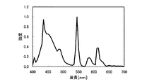
表1に、特許文献1の多原色液晶表示装置800における各サブ画素のY値、xy色度、主波長(マゼンタについては補色主波長)および色純度の一例とその表示品位とを示す。表1には、画素が白を表示したときのY値、xy色度および色温度も示している。各サブ画素のY値は、白表示時の画素のY値を100%とし、それに対する相対的な値を示している。なお、主波長および補色主波長は、色相を大まかに表し、色純度は、彩度を大まかに表すものである。また、ここで例示した構成に対応するカラーフィルタの分光透過率特性と、バックライトのスペクトルとを図3および図4に示す。 Table 1 shows an example of the Y value, xy chromaticity, dominant wavelength (complementary dominant wavelength for magenta), color purity, and display quality of each subpixel in the multi-primary color liquid

表1に示すように、赤、青、黄を表示するサブ画素R、B、Yeの表示品位が悪く、また、シアンを表示するサブ画素Cの表示品位も、緑、マゼンタを表示するサブ画素G、Mに比べるとやや悪い。しかしながら、表1に示す結果が、表示に用いる原色にそのままあてはまるわけではない。黄、シアン、マゼンタは、赤、緑、青の加法混色によっても表示することができるからである。これらの色(シアン、黄、マゼンタ)については、サブ画素Ye、CおよびMがそれぞれ単独で表示する色と、加法混色によって表示する色とを合わせて評価する必要がある。 As shown in Table 1, the display quality of the sub-pixels R, B, and Ye for displaying red, blue, and yellow is poor, and the display quality of the sub-pixel C for displaying cyan is also a sub-pixel that displays green and magenta. Slightly worse than G and M. However, the results shown in Table 1 do not directly apply to the primary colors used for display. This is because yellow, cyan, and magenta can be displayed by an additive color mixture of red, green, and blue. For these colors (cyan, yellow, and magenta), it is necessary to evaluate the colors displayed by the sub-pixels Ye, C, and M individually and the colors displayed by additive color mixing.
具体的には、黄については、赤サブ画素Rの表示する赤と緑サブ画素Gの表示する緑との混色によって表示される黄と、黄サブ画素Yeが単独で表示する黄とを合わせて評価する必要がある。また、シアンについては、緑サブ画素Gの表示する緑と青サブ画素Bの表示する青との混色によって表示されるシアンと、シアンサブ画素Cが単独で表示するシアンとを合せて評価する必要がある。さらに、マゼンタについては、赤サブ画素Rの表示する赤と青サブ画素Bの表示する青との混色によって表示されるマゼンタと、マゼンタサブ画素Mが単独で表示するマゼンタとを合せて評価する必要がある。 Specifically, for yellow, yellow displayed by a mixed color of red displayed by the red subpixel R and green displayed by the green subpixel G is combined with yellow displayed by the yellow subpixel Ye alone. Need to be evaluated. Further, regarding cyan, it is necessary to evaluate the cyan displayed by the mixed color of green displayed by the green sub-pixel G and blue displayed by the blue sub-pixel B and the cyan displayed by the cyan sub-pixel C alone. is there. Further, for magenta, it is necessary to evaluate the magenta displayed by the mixed color of red displayed by the red sub-pixel R and blue displayed by the blue sub-pixel B and the magenta displayed by the magenta sub-pixel M alone. There is.
表2に、液晶表示装置800の表示に用いられる原色のY値、xy色度、主波長(マゼンタについては補色主波長)および色純度の一例とその表示品位とを示す。 Table 2 shows examples of the Y value, xy chromaticity, primary wavelength (complementary primary wavelength for magenta) and color purity of the primary colors used for the display of the liquid
表2に示すように、黄、シアンについても十分な表示品位が得られていることがわかる。これは、他のサブ画素の加法混色による色が加味される結果、Y値が大きく向上する(ほぼ単純な算術和となる)からである。 As shown in Table 2, it can be seen that sufficient display quality is obtained for yellow and cyan. This is because the Y value is greatly improved (substantially simple arithmetic sum) as a result of adding the color by additive color mixing of other sub-pixels.
しかしながら、表2に示したように、赤については、依然として表示品位が低いままである。これは、原色の数を増やすことによってY値が低下しているためである。なお、ここで示した例では、青についても表示品位が低くなっているが、これは、試作に使用したカラーフィルタおよびバックライトの仕様によって偶々Y値が低くなりすぎたためである。青のY値の低下については、カラーフィルタおよびバックライトの仕様変更により解決し得るので、本質的な問題ではない。 However, as shown in Table 2, the display quality of red is still low. This is because the Y value is lowered by increasing the number of primary colors. In the example shown here, the display quality of blue is also low. This is because the Y value accidentally becomes too low due to the specifications of the color filter and backlight used in the trial production. The decrease in the Y value of blue is not an essential problem because it can be solved by changing the specifications of the color filter and the backlight.
続いて、表3に、本発明による液晶表示装置100における各サブ画素のY値、xy色度、主波長および色純度の一例とその表示品位とを示す。また、ここで例示した構成に対応するカラーフィルタの分光透過率特性と、バックライトのスペクトルとを図5および図6に示す。 Next, Table 3 shows an example of the Y value, xy chromaticity, dominant wavelength, and color purity of each sub-pixel in the liquid
表3に示すように、サブ画素単独で評価した場合には、第1の赤サブ画素R1、第2の赤サブ画素R2、黄サブ画素Yeの表示品位は良くない。また、シアンサブ画素Cの表示品位も、緑サブ画素Gや青サブ画素Bの表示品位にはやや劣る。しかしながら、本発明による液晶表示装置100においても、表3に示す結果がそのまま表示に用いる原色にあてはまるわけではない。つまり、表3に示す表示品位は、あくまでも「サブ画素の表示品位」であり、表示に用いる「原色の表示品位」ではない。 As shown in Table 3, when the sub-pixel alone is evaluated, the display quality of the first red sub-pixel R1, the second red sub-pixel R2, and the yellow sub-pixel Ye is not good. Further, the display quality of the cyan sub-pixel C is also slightly inferior to the display quality of the green sub-pixel G and the blue sub-pixel B. However, also in the liquid
黄やシアンについては、既に述べたように、黄サブ画素Yeやシアンサブ画素Cが単独で表示する色と、加法混色によって表示される色とを合せて評価する必要があり、赤については、第1の赤サブ画素R1の表示する赤と第2の赤サブ画素R2の表示する赤とを合せて評価する必要がある。また、本発明による液晶表示装置100においても、マゼンタを混色(第1および第2の赤サブ画素R1およびR2の表示する赤と青サブ画素Bの表示する青との混色)によって表示することができる。 As described above, for yellow and cyan, it is necessary to evaluate the color displayed by the yellow subpixel Ye and the cyan subpixel C alone and the color displayed by additive color mixture. It is necessary to evaluate the red displayed by the first red sub-pixel R1 together with the red displayed by the second red sub-pixel R2. Also in the liquid
表4に、本発明による液晶表示装置100の表示に用いられる原色のY値、xy色度、主波長(マゼンタについては補色主波長)および色純度の一例とその表示品位とを示す。 Table 4 shows an example of Y value, xy chromaticity, primary wavelength (complementary primary wavelength for magenta) and color purity used for display of the liquid
表4からわかるように、黄、シアンについては非常に良好な表示品位が得られている。また、マゼンタについても、非常に良好な表示品位が得られていることがわかる。さらに、赤についても、Y値が大きく向上し、そのことによって表示品位が大きく向上していることがわかる。 As can be seen from Table 4, very good display quality is obtained for yellow and cyan. It can also be seen that very good display quality is obtained for magenta. Furthermore, it can be seen that the red value for red is also greatly improved, which greatly improves the display quality.
ここで、特許文献1の液晶表示装置800と本発明による液晶表示装置100との赤の再現範囲の違いをより具体的に説明する。 Here, the difference in the red reproduction range between the liquid
図7に、特許文献1の液晶表示装置800および本発明による液晶表示装置100のそれぞれの、赤についてのC*−L*特性を示す。図7は、L*C*h表色系における色相角h=40°(赤に相当)についてC*とL*との関係を示すグラフである。C*は、L*a*b*表色系における√[(a*)2+(b*)2]に相当し、彩度を示す。また、L*は、XYZ表色系におけるY値に相当し、明度を示す。図7中には、点線によって物体色の赤の範囲を示している。FIG. 7 shows C * -L * characteristics of red in each of the liquid
図7からわかるように、液晶表示装置800では、赤の明度(L*)が低いために物体色の赤のすべてをカバーすることはできない。これに対し、本発明による液晶表示装置100では、赤の明度が高いために、物体色の赤をほぼカバーできており、特に、最も彩度の高い赤(図7中に丸で囲んでいる部分)つまり最も鮮やかな赤を再現できるので、色再現範囲を広くし、且つ、明るい赤を表示することが可能になる。As can be seen from FIG. 7, the liquid
また、特許文献1の液晶表示装置800がマゼンタを表示するサブ画素を有しているのに対し、本発明による液晶表示装置100は、マゼンタを表示するサブ画素を有していない。このことによるマゼンタ表示への影響を本願発明者は検討した。 Further, while the liquid
図8に、特許文献1の液晶表示装置800および本発明による液晶表示装置100のそれぞれの、マゼンタについてのC*−L*特性を示す。図8は、L*C*h表色系における色相角h=350°(マゼンタに相当)についてC*とL*との関係を示すグラフである。図8中には、点線によって物体色のマゼンタの範囲を示している。FIG. 8 shows C * -L * characteristics for magenta of the liquid
図8からわかるように、液晶表示装置800では、マゼンタのサブ画素が各画素に設けられているために、物体色のマゼンタがほぼカバーされており、最も彩度の高いマゼンタ(図8中に丸で囲んでいる部分)を再現できる。これに対し、本発明による液晶表示装置100では、マゼンタのサブ画素が設けられていないにも関わらず、物体色のマゼンタがほぼカバーされており、最も彩度の高いマゼンタ(つまり最も鮮やかなマゼンタ)を再現できる。図8からもわかるように、むしろ、本発明による液晶表示装置100の方が、カバーする範囲が広い。 As can be seen from FIG. 8, in the liquid
なお、マゼンタサブ画素を省略しても十分に物体色のマゼンタを再現できる理由は、図2に示されているように、物体色のマゼンタの外延がほぼ直線状だからであり、赤サブ画素R1およびR2と青サブ画素Bの色純度が十分に高ければ、加法混色によって物体色のマゼンタを十分に再現できるからである。これに対し、物体色の黄やシアンの外延は、図2に示すように丸みを帯びているため、黄サブ画素Yeやシアンサブ画素Cがなければ物体色の黄やシアンは再現しにくい。 The reason why the magenta of the object color can be sufficiently reproduced even if the magenta subpixel is omitted is that the extension of the magenta of the object color is substantially linear as shown in FIG. 2, and the red subpixel R1 This is because if the color purity of R2 and the blue subpixel B is sufficiently high, magenta of the object color can be sufficiently reproduced by additive color mixing. On the other hand, since the extension of yellow or cyan of the object color is rounded as shown in FIG. 2, the yellow or cyan of the object color is difficult to reproduce without the yellow sub-pixel Ye and the cyan sub-pixel C.
上述したように、本発明による液晶表示装置においては、色再現範囲が広く、且つ、明るい赤を表示することができる。なお、第1の赤サブ画素R1が表示する赤と、第2の赤サブ画素R1が表示する赤とは、同じであってもよいし、異なっていてもよい。これらが同じである場合には、カラーフィルタの作成プロセスを短縮できる。一方、これらが異なっている場合には、サブ画素で表示される原色が6つとなる(つまり色再現範囲が色度図上で六角形で表される)ので、再現できる色の数(特に赤近傍の表示色数)が増える。 As described above, the liquid crystal display device according to the present invention has a wide color reproduction range and can display bright red. Note that the red displayed by the first red sub-pixel R1 and the red displayed by the second red sub-pixel R1 may be the same or different. If they are the same, the color filter creation process can be shortened. On the other hand, if they are different, the number of primary colors displayed in the sub-pixel is six (that is, the color reproduction range is represented by a hexagon on the chromaticity diagram). The number of display colors in the vicinity increases.
続いて、液晶表示装置100の各サブ画素のY値、主波長および色純度の好ましい範囲を説明する。 Subsequently, a preferable range of the Y value, the dominant wavelength, and the color purity of each sub pixel of the liquid
忠実な色再現を行うためには、表示に用いる原色の明度すなわちY値を物体色の明度に従って決定することが好ましい。図9(a)〜(c)および図10(a)〜(c)に、赤(h=40°)、緑(h=160°)、青(h=310°)、黄(h=90°)、シアン(h=220°)およびマゼンタ(h=350°)について物体色のC*−L*特性を示す。In order to perform faithful color reproduction, it is preferable to determine the lightness of the primary color used for display, that is, the Y value according to the lightness of the object color. 9A to 9C and FIGS. 10A to 10C, red (h = 40 °), green (h = 160 °), blue (h = 310 °), yellow (h = 90). °), cyan (h = 220 °) and magenta (h = 350 °), the C * -L * characteristics of the object color are shown.
彩度の高い色を再現するためには、図9(a)〜(c)に示すように、赤のL*は38以上54以下、緑のL*は52以上66以下、青のL*は27以上38以下であることが好ましい。L*とY値とは、L*=116・Y1/3―16の関係を満足するので、この条件をL*ではなくY値で表すと、赤のY値は10%以上22%以下、緑のY値は20%以上35%以下、青のY値は5%以上10%以下であることが好ましい。In order to reproduce highly saturated colors, as shown in FIGS. 9A to 9C, red L * is 38 to 54, green L * is 52 to 66, and blue L *. Is preferably 27 or more and 38 or less. Since L * and Y value satisfy the relationship of L * = 116 · Y 1/3 -16, when this condition is expressed by Y value instead of L * , red Y value is 10% or more and 22% or less The green Y value is preferably 20% to 35%, and the blue Y value is preferably 5% to 10%.
また、同様に、彩度の高い色を再現するためには、図10(a)〜(c)に示すように、黄のL*は82以上94以下、シアンのL*は38以上79以下、マゼンタのL*は46以上62以下であることが好ましい。この条件をL*ではなくY値で表すと、黄のY値は60%以上85%以下、シアンのY値は10%以上55%以下、マゼンタのY値は15%以上30%以下であることが好ましい。Similarly, in order to reproduce a highly saturated color, as shown in FIGS. 10A to 10C, yellow L * is 82 to 94, and cyan L * is 38 to 79. The L * of magenta is preferably 46 or more and 62 or less. When this condition is expressed not by L * but by Y value, yellow Y value is 60% to 85%, cyan Y value is 10% to 55%, and magenta Y value is 15% to 30%. It is preferable.
Y値が低すぎると、たとえ彩度が高くても黒ずんだ色となる。例えば、赤は真紅、黄は黄土色、緑や青は黒に見えてしまう。逆にY値が高すぎると、発光色のような表示となり、違和感が生じる。特に、赤や緑についてはこの傾向が顕著である。なお、シアンについては、図10(b)からもわかるように比較的広いY値の範囲内で良好な表示が得られる。 If the Y value is too low, the color becomes dark even if the saturation is high. For example, red looks crimson, yellow looks ocher, and green and blue appear black. On the other hand, if the Y value is too high, the display is like a luminescent color, which causes a sense of incongruity. This tendency is particularly remarkable for red and green. For cyan, as shown in FIG. 10B, a good display can be obtained within a relatively wide range of Y values.
表5に、液晶表示装置100の表示に用いられる原色のY値、主波長、および色純度の好ましい範囲を示す。 Table 5 shows preferable ranges of the Y value of the primary color, the dominant wavelength, and the color purity used for the display of the liquid
既に説明したように、赤のY値は10%以上22%以下、緑のY値は20%以上35%以下、青のY値は5%以上10%以下であることが好ましく、黄のY値は60%以上85%以下、シアンのY値は10%以上55%以下、マゼンタのY値は15%以上30%以下であることが好ましい。 As already described, the red Y value is preferably 10% to 22%, the green Y value is preferably 20% to 35%, and the blue Y value is preferably 5% to 10%. The value is preferably 60% to 85%, the Y value of cyan is 10% to 55%, and the Y value of magenta is preferably 15% to 30%.
また、赤の主波長は605nm以上635nm以下、緑の主波長は520nm以上550nm以下、青の主波長は470nm以下であることが好ましく、黄の主波長は565nm以上580nm以下、シアンの主波長は475nm以上500nm以下であることが好ましい。 The red dominant wavelength is preferably 605 nm to 635 nm, the green dominant wavelength is preferably 520 nm to 550 nm, the blue dominant wavelength is preferably 470 nm or less, the yellow dominant wavelength is 565 nm to 580 nm, and the cyan dominant wavelength is It is preferable that it is 475 nm or more and 500 nm or less.
さらに、赤の色純度は90%以上、緑の色純度は65%以上80%以下、青の色純度は90%以上95%以下であることが好ましく、黄の色純度は85%以上95%以下、シアンの色純度は65%以上80%以下、マゼンタの色純度は60%以上80%以下であることが好ましい。 Further, the red color purity is preferably 90% or more, the green color purity is preferably 65% or more and 80% or less, the blue color purity is preferably 90% or more and 95% or less, and the yellow color purity is 85% or more and 95%. Hereinafter, the color purity of cyan is preferably 65% or more and 80% or less, and the color purity of magenta is preferably 60% or more and 80% or less.
赤については第1および第2の赤サブ画素R1およびR2が表示に寄与し、黄については第1、第2の赤サブ画素R1、R2、黄サブ画素Yeおよび緑サブ画素Gが表示に寄与する。また、シアンについては緑サブ画素G、シアンサブ画素Cおよび青サブ画素Bが表示に寄与し、マゼンタについては第1、第2の赤サブ画素R1、R2および青サブ画素Bが表示に寄与する。これらのことを考慮すると、液晶表示装置100の各サブ画素の主波長、Y値、色純度の好ましい範囲は、表6に示す通りとなる。 For red, the first and second red subpixels R1 and R2 contribute to the display, and for yellow, the first and second red subpixels R1, R2, the yellow subpixel Ye and the green subpixel G contribute to the display. To do. For cyan, the green sub-pixel G, cyan sub-pixel C, and blue sub-pixel B contribute to display, and for magenta, the first and second red sub-pixels R1, R2 and blue sub-pixel B contribute to display. Considering these, preferred ranges of the main wavelength, Y value, and color purity of each sub-pixel of the liquid
表6に示すように、第1および第2の赤サブ画素R1およびR2のY値はそれぞれ5%以上11%以下、緑サブ画素GのY値は20%以上35%以下、青サブ画素BのY値は5%以上10%以下であることが好ましく、黄サブ画素YeのY値は30%以上50%以下、シアンサブ画素CのY値は10%以上30%以下であることが好ましい。 As shown in Table 6, the Y values of the first and second red subpixels R1 and R2 are 5% to 11%, the Y value of the green subpixel G is 20% to 35%, and the blue subpixel B The Y value is preferably 5% or more and 10% or less, the Y value of the yellow subpixel Ye is preferably 30% or more and 50% or less, and the Y value of the cyan subpixel C is preferably 10% or more and 30% or less.
また、第1および第2の赤サブ画素R1およびR2の主波長はそれぞれ605nm以上635nm以下、緑サブ画素Gの主波長は520nm以上550nm以下、青サブ画素Bの主波長は470nm以下であることが好ましく、黄サブ画素Yeの主波長は565nm以上580nm以下、シアンサブ画素Cの主波長は475nm以上500nm以下であることが好ましい。 The primary wavelengths of the first and second red subpixels R1 and R2 are 605 nm to 635 nm, the primary wavelength of the green subpixel G is 520 nm to 550 nm, and the primary wavelength of the blue subpixel B is 470 nm or less. Preferably, the main wavelength of the yellow sub-pixel Ye is 565 nm to 580 nm and the main wavelength of the cyan sub-pixel C is 475 nm to 500 nm.
さらに、第1および第2の赤サブ画素R1およびR2のそれぞれの色純度は90%以上、緑サブ画素Gの色純度は65%以上80%以下、青サブ画素Bの色純度は90%以上95%以下であることが好ましく、黄サブ画素Yeの色純度は85%以上95%以下、シアンサブ画素Cの色純度は65%以上80%以下であることが好ましい。 Further, the color purity of each of the first and second red subpixels R1 and R2 is 90% or more, the color purity of the green subpixel G is 65% or more and 80% or less, and the color purity of the blue subpixel B is 90% or more. The color purity of the yellow subpixel Ye is preferably 85% or more and 95% or less, and the color purity of the cyan subpixel C is preferably 65% or more and 80% or less.
各サブ画素のY値、主波長、色純度を上述した好ましい範囲内に設定することによって、色再現範囲を広くし、且つ、明るい赤を表示するという本願発明の効果を高くすることができる。 By setting the Y value, dominant wavelength, and color purity of each sub-pixel within the above-described preferable ranges, the effect of the present invention of widening the color reproduction range and displaying bright red can be enhanced.
ここで、本発明による液晶表示装置100を、カラーフィルタおよびバックライトの仕様を変えて複数試作し、その表示品位を検証した結果を説明する。なお、以下では、表示品位の検証結果を表7から表20に示すが、表7、9、11、13、15、17および19中に示されている表示品位が「サブ画素の表示品位」であり、表8、10、12、14、16、18および20に示されている表示品位が「原色の表示品位」であることに留意されたい。 Here, a description will be given of a result of trial manufacture of a plurality of liquid
(実施例1)
表7に、本実施例における各サブ画素のY値、xy色度、主波長、色純度および表示品位を示し、表8に、本実施例における各原色のY値、xy色度、主波長(マゼンタについては補色主波長)、色純度および表示品位を示す。また、本実施例におけるカラーフィルタの分光透過率特性およびバックライトのスペクトルを、図11および図12に示す。Example 1
Table 7 shows the Y value, xy chromaticity, main wavelength, color purity, and display quality of each sub-pixel in this example, and Table 8 shows the Y value, xy chromaticity, main wavelength of each primary color in this example. (Complementary dominant wavelength for magenta), color purity and display quality. In addition, FIG. 11 and FIG. 12 show the spectral transmittance characteristics of the color filter and the backlight spectrum in this example.
表7に示すように、各サブ画素のY値、主波長および色純度は、概ね表6に示した好ましい数値範囲内である。そのため、表8に示すように、各原色のY値、主波長および色純度は、概ね表5に示した好ましい数値範囲内であり、全ての原色について非常に良好な表示品位が得られた。 As shown in Table 7, the Y value, dominant wavelength, and color purity of each subpixel are generally within the preferable numerical ranges shown in Table 6. Therefore, as shown in Table 8, the Y value, the dominant wavelength, and the color purity of each primary color are generally within the preferable numerical ranges shown in Table 5, and very good display quality was obtained for all the primary colors.
(実施例2)
表9に、本実施例における各サブ画素のY値等を示し、表10に、本実施例における各原色のY値等を示す。また、本実施例におけるカラーフィルタの分光透過率特性およびバックライトのスペクトルを、図13および図14に示す。(Example 2)
Table 9 shows the Y value and the like of each sub-pixel in this embodiment, and Table 10 shows the Y value and the like of each primary color in this embodiment. In addition, FIG. 13 and FIG. 14 show the spectral transmittance characteristics of the color filter and the backlight spectrum in this example.
表9に示すように、各サブ画素のY値、主波長および色純度は、概ね表6に示した好ましい数値範囲内である。そのため、表10に示すように、各原色のY値、主波長および色純度は、概ね表5に示した好ましい数値範囲内であり、赤、緑、黄およびシアンについて非常に良好な表示品位が得られ、青およびマゼンタについても良好な表示品位が得られた。 As shown in Table 9, the Y value, dominant wavelength, and color purity of each subpixel are generally within the preferable numerical ranges shown in Table 6. Therefore, as shown in Table 10, the Y value, dominant wavelength, and color purity of each primary color are generally within the preferable numerical ranges shown in Table 5, and very good display quality is shown for red, green, yellow, and cyan. Good display quality was also obtained for blue and magenta.
(実施例3)
表11に、本実施例における各サブ画素のY値等を示し、表12に、本実施例における各原色のY値等を示す。また、本実施例におけるカラーフィルタの分光透過率特性およびバックライトのスペクトルを、図15および図16に示す。(Example 3)
Table 11 shows the Y value and the like of each sub-pixel in this embodiment, and Table 12 shows the Y value and the like of each primary color in this embodiment. In addition, FIG. 15 and FIG. 16 show the spectral transmittance characteristics of the color filter and the backlight spectrum in this example.
表11に示すように、各サブ画素のY値、主波長および色純度は、概ね表6に示した好ましい数値範囲内である。そのため、表12に示すように、各原色のY値、主波長および色純度は、概ね表5に示した好ましい数値範囲内であり、赤、黄、シアンおよびマゼンタについて非常に良好な表示品位が得られ、緑および青についても良好な表示品位が得られた。 As shown in Table 11, the Y value, dominant wavelength, and color purity of each sub-pixel are generally within the preferable numerical range shown in Table 6. Therefore, as shown in Table 12, the Y value, dominant wavelength, and color purity of each primary color are generally within the preferred numerical ranges shown in Table 5, and very good display quality is shown for red, yellow, cyan, and magenta. Good display quality was also obtained for green and blue.
(実施例4)
表13に、本実施例における各サブ画素のY値等を示し、表14に、本実施例における各原色のY値等を示す。また、本実施例におけるカラーフィルタの分光透過率特性およびバックライトのスペクトルを、図17および図18に示す。Example 4
Table 13 shows the Y value and the like of each sub-pixel in this embodiment, and Table 14 shows the Y value and the like of each primary color in this embodiment. In addition, FIG. 17 and FIG. 18 show the spectral transmittance characteristics of the color filter and the backlight spectrum in this example.
表13に示すように、各サブ画素のY値、主波長および色純度は、概ね表6に示した好ましい数値範囲内である。そのため、表14に示すように、各原色のY値、主波長および色純度は、概ね表5に示した好ましい数値範囲内であり、赤、緑、黄、シアンおよびマゼンタについて非常に良好な表示品位が得られ、青についても良好な表示品位が得られた。 As shown in Table 13, the Y value, dominant wavelength, and color purity of each subpixel are generally within the preferable numerical ranges shown in Table 6. Therefore, as shown in Table 14, the Y value, dominant wavelength, and color purity of each primary color are generally within the preferable numerical ranges shown in Table 5, and very good display is achieved for red, green, yellow, cyan, and magenta. Quality was obtained, and good display quality was also obtained for blue.
(実施例5)
表15に、本実施例における各サブ画素のY値等を示し、表16に、本実施例における各原色のY値等を示す。また、本実施例におけるカラーフィルタの分光透過率特性およびバックライトのスペクトルを、図19および図20に示す。(Example 5)
Table 15 shows the Y value and the like of each sub-pixel in this embodiment, and Table 16 shows the Y value and the like of each primary color in this embodiment. In addition, FIG. 19 and FIG. 20 show the spectral transmittance characteristics of the color filter and the backlight spectrum in this example.
表15に示すように、各サブ画素のY値、主波長および色純度は、概ね表6に示した好ましい数値範囲内である。そのため、表16に示すように、各原色のY値、主波長および色純度は、概ね表5に示した好ましい数値範囲内であり、赤、青、黄、シアンおよびマゼンタについて非常に良好な表示品位が得られ、緑についても良好な表示品位が得られた。 As shown in Table 15, the Y value, dominant wavelength, and color purity of each sub-pixel are generally within the preferable numerical ranges shown in Table 6. Therefore, as shown in Table 16, the Y value, dominant wavelength, and color purity of each primary color are generally within the preferable numerical ranges shown in Table 5, and very good display is achieved for red, blue, yellow, cyan, and magenta. Quality was obtained, and good display quality was also obtained for green.
(実施例6)
表17に、本実施例における各サブ画素のY値等を示し、表18に、本実施例における各原色のY値等を示す。また、本実施例におけるカラーフィルタの分光透過率特性およびバックライトのスペクトルを、図21および図22に示す。(Example 6)
Table 17 shows the Y value and the like of each sub-pixel in this embodiment, and Table 18 shows the Y value and the like of each primary color in this embodiment. In addition, FIG. 21 and FIG. 22 show the spectral transmittance characteristics of the color filter and the backlight spectrum in this example.
表17に示すように、各サブ画素のY値、主波長および色純度は、概ね表6に示した好ましい数値範囲内である。そのため、表18に示すように、各原色のY値、主波長および色純度は、概ね表5に示した好ましい数値範囲内であり、赤、緑、黄およびマゼンタについて非常に良好な表示品位が得られ、青およびシアンについても良好な表示品位が得られた。 As shown in Table 17, the Y value, dominant wavelength, and color purity of each sub-pixel are generally within the preferable numerical range shown in Table 6. Therefore, as shown in Table 18, the Y value, dominant wavelength, and color purity of each primary color are generally within the preferred numerical ranges shown in Table 5, and very good display quality is shown for red, green, yellow, and magenta. Good display quality was also obtained for blue and cyan.
(実施例7)
表19に、本実施例における各サブ画素のY値等を示し、表20に、本実施例における各原色のY値等を示す。また、本実施例におけるカラーフィルタの分光透過率特性およびバックライトのスペクトルを、図23および図24に示す。(Example 7)
Table 19 shows the Y value and the like of each sub-pixel in this embodiment, and Table 20 shows the Y value and the like of each primary color in this embodiment. In addition, FIG. 23 and FIG. 24 show the spectral transmittance characteristics of the color filter and the spectrum of the backlight in this example.
表19に示すように、各サブ画素のY値、主波長および色純度は、概ね表6に示した好ましい数値範囲内である。そのため、表20に示すように、各原色のY値、主波長および色純度は、概ね表5に示した好ましい数値範囲内であり、緑、黄、青、シアンおよびマゼンタについて非常に良好な表示品位が得られ、赤についても良好な表示品位が得られた。 As shown in Table 19, the Y value, dominant wavelength, and color purity of each sub-pixel are generally within the preferable numerical range shown in Table 6. Therefore, as shown in Table 20, the Y value, dominant wavelength, and color purity of each primary color are generally within the preferable numerical ranges shown in Table 5, and very good display is obtained for green, yellow, blue, cyan, and magenta. Quality was obtained, and good display quality was also obtained for red.
(実施例8)
表21に、本実施例における各サブ画素のY値等を示し、表22に、本実施例における各原色のY値等を示す。また、本実施例におけるカラーフィルタの分光透過率特性およびバックライトのスペクトルを、図25および図26に示す。(Example 8)
Table 21 shows the Y value and the like of each sub-pixel in this embodiment, and Table 22 shows the Y value and the like of each primary color in this embodiment. In addition, FIG. 25 and FIG. 26 show the spectral transmittance characteristics of the color filter and the backlight spectrum in this example.
表21に示すように、第1および第2の赤サブ画素R1およびR2のY値は、表6に示した好ましい数値範囲(5%以上11%以下)内にはなく、4%とやや低い。そのため、赤のY値を十分に高くすることができず、表22に示すように、赤のY値は、表5に示した好ましい数値範囲(10%以上22%以下)内ではなく、7.9%とやや低い。従って、実施例1〜7に比べると、赤の表示がやや暗くなる。また、第1および第2の赤サブ画素R1およびR2のY値がやや低いため、マゼンタのY値を十分に高くすることができず、表22に示すように、マゼンタのY値は、表5に示した好ましい数値範囲(15%以上30%以下)内ではなく、13.1%とやや低い。従って、実施例1〜7に比べると、マゼンタの表示もやや暗くなる。 As shown in Table 21, the Y values of the first and second red sub-pixels R1 and R2 are not within the preferable numerical range shown in Table 6 (5% or more and 11% or less), and are slightly low at 4%. . Therefore, the red Y value cannot be made sufficiently high, and as shown in Table 22, the red Y value is not within the preferable numerical range shown in Table 5 (10% or more and 22% or less). It is a little low at 9%. Therefore, compared with Examples 1-7, a red display becomes a little dark. Further, since the Y values of the first and second red sub-pixels R1 and R2 are slightly low, the Y value of magenta cannot be made sufficiently high. As shown in Table 22, the Y value of magenta It is not within the preferable numerical range (15% or more and 30% or less) shown in FIG. Therefore, the display of magenta is slightly darker than in the first to seventh embodiments.
続いて、画素内におけるサブ画素の好ましい配置を説明する。 Subsequently, a preferable arrangement of sub-pixels in the pixel will be described.
まず、図27(a)〜(e)に、第1の赤サブ画素R1および第2の赤サブ画素R2の好ましい配置例を示す。図27中、サブ画素X1、X2、X3およびX4は、緑サブ画素G、青サブ画素B、黄サブ画素Yeおよびシアンサブ画素Cのいずれかである。 First, FIGS. 27A to 27E show preferable arrangement examples of the first red sub-pixel R1 and the second red sub-pixel R2. In FIG. 27, subpixels X1, X2, X3, and X4 are any one of green subpixel G, blue subpixel B, yellow subpixel Ye, and cyan subpixel C.
第1の赤サブ画素R1と第2の赤サブ画素R2とは、図27(a)〜(e)に示すように、画素内において連続するように配置されていることが好ましい。第1の赤サブ画素R1と第2の赤サブ画素R2とが画素内で離れている(つまり他のサブ画素を挟むように配置されている)と、赤のラインを表示したときにぶつぶつして見えることがある。第1の赤サブ画素R1と第2の赤サブ画素R2とを連続するように配置すると、そのようなぶつぶつ感の発生を防止することができる。 The first red sub-pixel R1 and the second red sub-pixel R2 are preferably arranged so as to be continuous in the pixel as shown in FIGS. When the first red sub-pixel R1 and the second red sub-pixel R2 are separated within the pixel (that is, arranged so as to sandwich another sub-pixel), the red line is displayed when the red line is displayed. May appear. If the first red sub-pixel R1 and the second red sub-pixel R2 are arranged so as to be continuous, it is possible to prevent the occurrence of such a crushing feeling.
次に、図28(a)〜(f)に、緑サブ画素Gおよび黄サブ画素Yeの好ましい配置例を示す。図28中、サブ画素X1、X2、X3およびX4は、第1の赤サブ画素R1、第2の赤サブ画素R2、青サブ画素Bおよびシアンサブ画素Cのいずれかである。 Next, FIGS. 28A to 28F show preferable arrangement examples of the green sub-pixel G and the yellow sub-pixel Ye. In FIG. 28, subpixels X1, X2, X3, and X4 are any of the first red subpixel R1, the second red subpixel R2, the blue subpixel B, and the cyan subpixel C.
緑サブ画素Gと黄サブ画素Yeとは、図28(a)〜(f)に示すように、画素内において連続し、且つ、他のサブ画素によって挟まれるように(つまり画素の端部に位置しないように)配置されていることが好ましい。表6などに示しているように、緑サブ画素Gおよび黄サブ画素Yeは、他のサブ画素に比べてY値が高い。そのため、図示したように緑サブ画素Gおよび黄サブ画素Yeを画素の中央に近い部分に配置することによって、文字を表示したときのエッジの色付きなどの問題を抑制することができる。 As shown in FIGS. 28A to 28F, the green sub-pixel G and the yellow sub-pixel Ye are continuous in the pixel and sandwiched by other sub-pixels (that is, at the end of the pixel). It is preferred that they are arranged (so as not to be located). As shown in Table 6 and the like, the green sub-pixel G and the yellow sub-pixel Ye have higher Y values than the other sub-pixels. Therefore, by arranging the green sub-pixel G and the yellow sub-pixel Ye near the center of the pixel as illustrated, problems such as coloring of the edge when displaying characters can be suppressed.
続いて、図29(a)〜(f)に、第1の赤サブ画素R1、第2の赤サブ画素R2、緑サブ画素Gおよび黄サブ画素Yeの好ましい配置例を示す。図29中、サブ画素X1およびX2は、青サブ画素Bまたはシアンサブ画素Cのいずれかである。 Subsequently, FIGS. 29A to 29F show preferable arrangement examples of the first red sub-pixel R1, the second red sub-pixel R2, the green sub-pixel G, and the yellow sub-pixel Ye. In FIG. 29, the sub-pixels X1 and X2 are either the blue sub-pixel B or the cyan sub-pixel C.
第1の赤サブ画素R1、第2の赤サブ画素R2、緑サブ画素Gおよび黄サブ画素Yeは、図29(a)〜(f)に示すように、画素内において連続するように配置されていることが好ましい。黄の表示に寄与するこれらのサブ画素を、画素内で連続するように配置することにより、黄のラインを表示したときのぶつぶつ感の発生を防止することができる。また、図29(a)〜(f)に示す配置では、第1の赤サブ画素R1と第2の赤サブ画素R2とが連続しているので、赤のラインを表示したときのぶつぶつ感の発生も防止することができる。さらに、図29(a)、(b)、(e)および(f)に示す配置では、緑サブ画素Gと黄サブ画素Yeとが連続し、且つ、他のサブ画素によって挟まれるように配置されているので、文字を表示したときのエッジの色付きも防止することができる。 The first red sub-pixel R1, the second red sub-pixel R2, the green sub-pixel G, and the yellow sub-pixel Ye are arranged so as to be continuous in the pixel as shown in FIGS. It is preferable. By arranging these sub-pixels that contribute to yellow display so as to be continuous in the pixel, it is possible to prevent the occurrence of crushing feeling when the yellow line is displayed. Further, in the arrangement shown in FIGS. 29A to 29F, the first red sub-pixel R1 and the second red sub-pixel R2 are continuous, so that the feeling of crushing when a red line is displayed is displayed. Occurrence can also be prevented. Furthermore, in the arrangements shown in FIGS. 29A, 29B, 29E, and 29F, the green sub-pixel G and the yellow sub-pixel Ye are arranged continuously and sandwiched between other sub-pixels. Therefore, coloring of the edge when displaying the character can be prevented.
次に、図30(a)〜(d)に、シアンサブ画素C、緑サブ画素Gおよび青サブ画素Bの好ましい配置例を示す。図30中、サブ画素X1およびX2は第1の赤サブ画素R1および第2の赤サブ画素R2のいずれかである。 Next, FIGS. 30A to 30D show preferable arrangement examples of the cyan sub-pixel C, the green sub-pixel G, and the blue sub-pixel B. FIG. In FIG. 30, subpixels X1 and X2 are either the first red subpixel R1 or the second red subpixel R2.
シアンサブ画素C、緑サブ画素Gおよび青サブ画素Bは、図30(a)〜(d)に示すように、画素内において連続するように配置されていることが好ましい。シアンの表示に寄与するこれらのサブ画素を、画素内で連続するように配置することによって、シアンのラインを表示したときのぶつぶつ感の発生を防止することができる。また、図30(a)〜(d)に示す配置では、緑サブ画素Gと黄サブ画素Yeとが連続し、且つ、他のサブ画素によって挟まれるように配置されているので、文字を表示したときのエッジの色付きも防止することができる。 As shown in FIGS. 30A to 30D, the cyan sub pixel C, the green sub pixel G, and the blue sub pixel B are preferably arranged so as to be continuous in the pixel. By arranging these sub-pixels that contribute to the display of cyan so as to be continuous in the pixel, it is possible to prevent the occurrence of a crushing feeling when displaying a cyan line. In the arrangement shown in FIGS. 30A to 30D, the green sub-pixel G and the yellow sub-pixel Ye are arranged so as to be continuous and sandwiched between other sub-pixels, so that characters are displayed. It is also possible to prevent the edge from being colored.
続いて、図31(a)および(b)に、すべてのサブ画素の好ましい配置例を示す。図31(a)および(b)に示す配置では、第1の赤サブ画素R1と第2の赤サブ画素R2とが連続しているので、赤のラインを表示したときのぶつぶつ感の発生を防止することができる。また、緑サブ画素Gと黄サブ画素Yeとが連続し、且つ、他のサブ画素によって挟まれているので、文字を表示したときのエッジの色付きも防止することができる。さらに、黄の表示に寄与するサブ画素(つまり第1の赤サブ画素R1、第2の赤サブ画素R2、緑サブ画素Gおよび黄サブ画素Ye)が連続しているので、黄のラインを表示したときのぶつぶつ感の発生も防止することができる。そして、シアンの表示に寄与するサブ画素(つまりシアンサブ画素C、緑サブ画素Gおよび青サブ画素B)が連続しているので、シアンのラインを表示したときのぶつぶつ感の発生も防止することができる。 Next, FIGS. 31A and 31B show a preferable arrangement example of all the sub-pixels. In the arrangements shown in FIGS. 31A and 31B, the first red sub-pixel R1 and the second red sub-pixel R2 are continuous. Can be prevented. Further, since the green sub-pixel G and the yellow sub-pixel Ye are continuous and sandwiched between other sub-pixels, it is possible to prevent coloring of the edge when displaying characters. Further, since the sub-pixels that contribute to yellow display (that is, the first red sub-pixel R1, the second red sub-pixel R2, the green sub-pixel G, and the yellow sub-pixel Ye) are continuous, the yellow line is displayed. It is also possible to prevent the occurrence of crushing feeling. Further, since the sub-pixels contributing to cyan display (that is, the cyan sub-pixel C, the green sub-pixel G, and the blue sub-pixel B) are continuous, it is possible to prevent the occurrence of the crushing feeling when the cyan line is displayed. it can.
なお、ここまでは、図1に示すように1つの画素内で複数のサブ画素が1行に配置されている場合を例として本発明を説明したが、図32に示す液晶表示装置200のように、複数のサブ画素が画素P内で複数行複数列(ここでは2行3列)に配置されていてもよい。このようなモザイク状の配置を採用しても、図1に示した液晶表示装置100と同様に、色再現範囲を広くし、且つ、明るい赤を表示することが可能になる。 Heretofore, the present invention has been described by taking as an example the case where a plurality of sub-pixels are arranged in one row as shown in FIG. 1, but like the liquid
ここで、モザイク状の配置を採用した場合のサブ画素の好ましい配置を説明する。 Here, a preferable arrangement of sub-pixels when a mosaic arrangement is employed will be described.
まず、図33(a)〜(c)に、第1の赤サブ画素R1および第2の赤サブ画素R2の好ましい配置例を示す。図33中、サブ画素X1、X2、X3およびX4は、緑サブ画素G、青サブ画素B、黄サブ画素Yeおよびシアンサブ画素Cのいずれかである。 First, FIGS. 33A to 33C show a preferable arrangement example of the first red sub-pixel R1 and the second red sub-pixel R2. In FIG. 33, subpixels X1, X2, X3, and X4 are any of green subpixel G, blue subpixel B, yellow subpixel Ye, and cyan subpixel C.
第1の赤サブ画素R1と第2の赤サブ画素R2とを、図33(a)〜(c)に示すように画素内において連続するように配置することによって、赤のラインを表示したときのぶつぶつ感の発生を防止することができる。 When the red line is displayed by arranging the first red sub-pixel R1 and the second red sub-pixel R2 so as to be continuous in the pixel as shown in FIGS. Occurrence of a crushed feeling can be prevented.
次に、図34(a)および(b)に、緑サブ画素Gおよび黄サブ画素Yeの好ましい配置例を示す。図34中、サブ画素X1、X2、X3およびX4は、第1の赤サブ画素R1、第2の赤サブ画素R2、青サブ画素Bおよびシアンサブ画素Cのいずれかである。 Next, FIGS. 34A and 34B show a preferable arrangement example of the green sub-pixel G and the yellow sub-pixel Ye. In FIG. 34, subpixels X1, X2, X3, and X4 are any of the first red subpixel R1, the second red subpixel R2, the blue subpixel B, and the cyan subpixel C.
緑サブ画素Gと黄サブ画素Yeとを、図34(a)および(b)に示すように、画素内において連続し、且つ、他のサブ画素によって挟まれるように(つまり画素の端部に位置しないように)配置することによって、文字を表示したときのエッジの色付きを防止することができる。 As shown in FIGS. 34A and 34B, the green sub-pixel G and the yellow sub-pixel Ye are continuous in the pixel and sandwiched between other sub-pixels (that is, at the end of the pixel). By arranging (not to be positioned), it is possible to prevent coloring of the edge when displaying the character.
続いて、図35(a)〜(d)に、第1の赤サブ画素R1、第2の赤サブ画素R2、緑サブ画素Gおよび黄サブ画素Yeの好ましい配置例を示す。図35中、サブ画素X1およびX2は、青サブ画素Bまたはシアンサブ画素Cのいずれかである。 Subsequently, FIGS. 35A to 35D show preferable arrangement examples of the first red sub-pixel R1, the second red sub-pixel R2, the green sub-pixel G, and the yellow sub-pixel Ye. In FIG. 35, the sub-pixels X1 and X2 are either the blue sub-pixel B or the cyan sub-pixel C.
第1の赤サブ画素R1、第2の赤サブ画素R2、緑サブ画素Gおよび黄サブ画素Yeは、図35(a)〜(d)に示すように、画素内において連続するように配置されていることが好ましい。黄の表示に寄与するこれらのサブ画素を、画素内で連続するように配置することにより、黄のラインを表示したときのぶつぶつ感の発生を防止することができる。また、図35(a)〜(d)に示す配置では、第1の赤サブ画素R1と第2の赤サブ画素R2とが連続しているので、赤のラインを表示したときのぶつぶつ感の発生も防止することができる。さらに、図35(a)〜(d)に示す配置では、緑サブ画素Gと黄サブ画素Yeとが連続し、且つ、他のサブ画素によって挟まれるように配置されているので、文字を表示したときのエッジの色付きも防止することができる。 The first red sub-pixel R1, the second red sub-pixel R2, the green sub-pixel G, and the yellow sub-pixel Ye are arranged so as to be continuous in the pixel as shown in FIGS. It is preferable. By arranging these sub-pixels that contribute to yellow display so as to be continuous in the pixel, it is possible to prevent the occurrence of crushing feeling when the yellow line is displayed. In the arrangements shown in FIGS. 35A to 35D, the first red sub-pixel R1 and the second red sub-pixel R2 are continuous, so that the feeling of crushing when a red line is displayed is displayed. Occurrence can also be prevented. Further, in the arrangement shown in FIGS. 35A to 35D, the green sub-pixel G and the yellow sub-pixel Ye are arranged so as to be continuous and sandwiched by other sub-pixels, so that characters are displayed. It is also possible to prevent the edge from being colored.
次に、図36(a)〜(d)に、シアンサブ画素C、緑サブ画素Gおよび青サブ画素Bの好ましい配置例を示す。図36中、サブ画素X1およびX2は第1の赤サブ画素R1および第2の赤サブ画素R2のいずれかである。 Next, FIGS. 36A to 36D show preferable arrangement examples of the cyan sub-pixel C, the green sub-pixel G, and the blue sub-pixel B. FIG. In FIG. 36, subpixels X1 and X2 are either the first red subpixel R1 or the second red subpixel R2.
シアンサブ画素C、緑サブ画素Gおよび青サブ画素Bは、図36(a)〜(d)に示すように、画素内において連続するように配置されていることが好ましい。シアンの表示に寄与するこれらのサブ画素を、画素内で連続するように配置することによって、シアンのラインを表示したときのぶつぶつ感の発生を防止することができる。また、図36(a)〜(d)に示す配置では、緑サブ画素Gと黄サブ画素Yeとが連続し、且つ、他のサブ画素によって挟まれるように配置されているので、文字を表示したときのエッジの色付きも防止することができる。 The cyan sub-pixel C, the green sub-pixel G, and the blue sub-pixel B are preferably arranged so as to be continuous in the pixel as shown in FIGS. By arranging these sub-pixels that contribute to the display of cyan so as to be continuous in the pixel, it is possible to prevent the occurrence of a crushing feeling when displaying a cyan line. In the arrangements shown in FIGS. 36A to 36D, the green sub-pixel G and the yellow sub-pixel Ye are arranged so as to be continuous and sandwiched between other sub-pixels, so that characters are displayed. It is also possible to prevent the edge from being colored.
続いて、図37(a)〜(d)に、すべてのサブ画素の好ましい配置例を示す。図37(a)〜(d)に示す配置では、第1の赤サブ画素R1と第2の赤サブ画素R2とが連続しているので、赤のラインを表示したときのぶつぶつ感の発生を防止することができる。また、緑サブ画素Gと黄サブ画素Yeとが連続し、且つ、他のサブ画素によって挟まれているので、文字を表示したときのエッジの色付きも防止することができる。さらに、黄の表示に寄与するサブ画素(つまり第1の赤サブ画素R1、第2の赤サブ画素R2、緑サブ画素Gおよび黄サブ画素Ye)が連続しているので、黄のラインを表示したときのぶつぶつ感の発生も防止することができる。そして、シアンの表示に寄与するサブ画素(つまりシアンサブ画素C、緑サブ画素Gおよび青サブ画素B)が連続しているので、シアンのラインを表示したときのぶつぶつ感の発生も防止することができる。 Subsequently, FIGS. 37A to 37D show preferable arrangement examples of all the sub-pixels. In the arrangements shown in FIGS. 37A to 37D, the first red sub-pixel R1 and the second red sub-pixel R2 are continuous, so that the occurrence of a crushing feeling when displaying a red line is generated. Can be prevented. Further, since the green sub-pixel G and the yellow sub-pixel Ye are continuous and sandwiched between other sub-pixels, it is possible to prevent coloring of the edge when displaying characters. Further, since the sub-pixels that contribute to yellow display (that is, the first red sub-pixel R1, the second red sub-pixel R2, the green sub-pixel G, and the yellow sub-pixel Ye) are continuous, the yellow line is displayed. It is also possible to prevent the occurrence of crushing feeling. Further, since the sub-pixels contributing to cyan display (that is, the cyan sub-pixel C, the green sub-pixel G, and the blue sub-pixel B) are continuous, it is possible to prevent the occurrence of the crushing feeling when the cyan line is displayed. it can.
また、図38(a)および(b)に示すように、黄サブ画素Yeとシアンサブ画素Cとを、画素内において連続し、且つ、他のサブ画素によって挟まれるように(つまり画素の端部に位置しないように)配置することも好ましい。図38中、サブ画素X1、X2、X3およびX4は、第1の赤サブ画素R1、第2の赤サブ画素R2、緑サブ画素Gおよび青サブ画素Bのいずれかである。表6などに示しているように、シアンサブ画素Cも、黄サブ画素Yeや緑サブ画素Gほどではないものの、Y値が高い。そのため、図示したように黄サブ画素Yeおよびシアンサブ画素Cを画素の中央に近い部分に配置することによっても、文字を表示したときのエッジの色付きを抑制するという効果を得ることができる。 Also, as shown in FIGS. 38A and 38B, the yellow sub-pixel Ye and the cyan sub-pixel C are continuous in the pixel and are sandwiched by other sub-pixels (that is, the end portion of the pixel). It is also preferable to arrange it so that it is not located in the position. In FIG. 38, subpixels X1, X2, X3, and X4 are any of the first red subpixel R1, the second red subpixel R2, the green subpixel G, and the blue subpixel B. As shown in Table 6 and the like, the cyan sub-pixel C also has a high Y value although not as high as the yellow sub-pixel Ye and the green sub-pixel G. Therefore, by arranging the yellow sub-pixel Ye and the cyan sub-pixel C in a portion close to the center of the pixel as shown in the figure, it is possible to obtain the effect of suppressing the coloring of the edge when the character is displayed.
図39(a)〜(d)に、他の好ましい配置例を示す。図39中、サブ画素X1およびX2は、サブ画素Gおよび青サブ画素Bのいずれかである。図39(a)〜(d)に示す配置では、第1の赤サブ画素R1と第2の赤サブ画素R2とが連続しているので、赤のラインを表示したときのぶつぶつ感の発生を防止することができる。また、黄サブ画素Yeとシアンサブ画素Cとが連続し、且つ、他のサブ画素によって挟まれているので、文字を表示したときのエッジの色付きも防止することができる。 39A to 39D show other preferable arrangement examples. In FIG. 39, the sub-pixels X1 and X2 are either the sub-pixel G or the blue sub-pixel B. In the arrangements shown in FIGS. 39A to 39D, since the first red sub-pixel R1 and the second red sub-pixel R2 are continuous, the occurrence of the crushing feeling when the red line is displayed is generated. Can be prevented. Further, since the yellow sub-pixel Ye and the cyan sub-pixel C are continuous and sandwiched between other sub-pixels, it is possible to prevent coloring of the edge when displaying characters.
なお、ここまでの説明では、6つのサブ画素によって1つの画素が規定される構成を例示したが、本発明はこれに限定されるものではない。さらに多く(7つ以上)のサブ画素によって1つの画素が規定される構成や、5つのサブ画素によって1つの画素が規定される構成においても、画素が第1の赤サブ画素R1と第2の赤サブ画素R2とを含むことにより、明るい赤を表示するという効果が得られる。 In the above description, a configuration in which one pixel is defined by six sub-pixels is illustrated, but the present invention is not limited to this. Even in a configuration in which one pixel is defined by more (seven or more) sub-pixels, or in a configuration in which one pixel is defined by five sub-pixels, the pixels are the first red sub-pixel R1 and the second sub-pixel. By including the red sub-pixel R2, an effect of displaying bright red can be obtained.
図40(a)および(b)に、5つのサブ画素によって規定される画素の例を示す。図40(a)および(b)に示す画素は、第1の赤サブ画素R1、第2の赤サブ画素R2、緑サブ画素G、青サブ画素Bおよび黄サブ画素Yeによって規定されており、図31(a)および(b)に例示した画素から、シアンサブ画素Cを除いたものに相当する。 FIGS. 40A and 40B show examples of pixels defined by five subpixels. The pixels shown in FIGS. 40A and 40B are defined by the first red sub-pixel R1, the second red sub-pixel R2, the green sub-pixel G, the blue sub-pixel B, and the yellow sub-pixel Ye, This corresponds to the pixel illustrated in FIGS. 31A and 31B excluding the cyan sub-pixel C.
図40(a)および(b)に示すような構成を採用しても、画素に黄サブ画素Yeが含まれているので、三原色を用いて表示を行う従来の一般的な液晶表示装置に比べて色再現範囲を広くすることができる。また、画素に第1の赤サブ画素R1と第2の赤サブ画素R2とが含まれているので、明るい赤を表示することも可能になる。 Even if the configuration as shown in FIGS. 40A and 40B is adopted, the pixel includes the yellow sub-pixel Ye, and therefore, compared with a conventional general liquid crystal display device that performs display using three primary colors. Can widen the color reproduction range. In addition, since the pixel includes the first red sub-pixel R1 and the second red sub-pixel R2, bright red can be displayed.
また、5つのサブ画素によって1つの画素を規定する場合であっても、図40(a)および(b)に例示しているように、第1の赤サブ画素R1と第2の赤サブ画素R2とが連続していることが好ましく、緑サブ画素Gと黄サブ画素Yeとが連続し、且つ、他のサブ画素によって挟まれていることが好ましい。また、黄の表示に寄与するサブ画素(つまり第1の赤サブ画素R1、第2の赤サブ画素R2、緑サブ画素Gおよび黄サブ画素Ye)が連続していることが好ましく、シアンの表示に寄与するサブ画素(つまり緑サブ画素Gおよび青サブ画素B)が連続していることが好ましい。 Even when one pixel is defined by five sub-pixels, as illustrated in FIGS. 40A and 40B, the first red sub-pixel R1 and the second red sub-pixel R2 is preferably continuous, and the green subpixel G and the yellow subpixel Ye are preferably continuous and sandwiched between other subpixels. Further, it is preferable that the sub-pixels that contribute to yellow display (that is, the first red sub-pixel R1, the second red sub-pixel R2, the green sub-pixel G, and the yellow sub-pixel Ye) are continuous, and cyan display It is preferable that the sub-pixels contributing to (ie, the green sub-pixel G and the blue sub-pixel B) are continuous.
なお、5つのサブ画素によって1つの画素を規定する場合、画素にはシアンサブ画素Cよりも黄サブ画素Yeが含まれていることが好ましい。黄サブ画素Yeは、シアンサブ画素CよりもY値が高いため、黄サブ画素Yeが含まれている方が画素全体で明るい表示が可能となる。 When one pixel is defined by five subpixels, the pixel preferably includes the yellow subpixel Ye rather than the cyan subpixel C. Since the yellow sub-pixel Ye has a higher Y value than the cyan sub-pixel C, the entire pixel can be brightly displayed when the yellow sub-pixel Ye is included.
また、これまでは、画素を規定する複数のサブ画素が実質的に同じ大きさを有する構成を図示したが、図41に示すように、画素を規定する複数のサブ画素は異なった大きさを有してもよい。図41に示す構成では、緑サブ画素Gおよび黄サブ画素Yeが、第1の赤サブ画素R1、第2の赤サブ画素R2および青サブ画素Bの1.5倍の大きさを有している。このような構成であっても、明るい赤を表示することができる。なお、図41に例示した配置は、第1の赤サブ画素R1および第2の赤サブ画素R2が連続している点で好ましく、黄の表示に寄与するサブ画素(つまり第1の赤サブ画素R1、第2の赤サブ画素R2、緑サブ画素Gおよび黄サブ画素Ye)が連続している点でも好ましい。 In addition, until now, a configuration in which a plurality of sub-pixels defining a pixel have substantially the same size has been illustrated, but as shown in FIG. 41, a plurality of sub-pixels defining a pixel have different sizes. You may have. In the configuration shown in FIG. 41, the green sub-pixel G and the yellow sub-pixel Ye have 1.5 times the size of the first red sub-pixel R1, the second red sub-pixel R2, and the blue sub-pixel B. Yes. Even with such a configuration, bright red can be displayed. The arrangement illustrated in FIG. 41 is preferable in that the first red subpixel R1 and the second red subpixel R2 are continuous, and is a subpixel that contributes to yellow display (that is, the first red subpixel). R1, second red sub-pixel R2, green sub-pixel G and yellow sub-pixel Ye) are also preferred in that they are continuous.
ただし、大きさの異なるサブ画素を設けると、表示装置の設計を困難にしたり、表示装置の製造工程を複雑にしたりすることがある。画素を規定する複数のサブ画素が実質的に同じ大きさを有していると、このような問題が発生しない。 However, providing sub-pixels having different sizes may make it difficult to design the display device or complicate the manufacturing process of the display device. If a plurality of sub-pixels defining a pixel have substantially the same size, such a problem does not occur.
続いて、本実施形態における液晶表示装置100および200のより具体的な構造を説明する。 Next, more specific structures of the liquid
液晶表示装置100および200は、例えば、図42に示すように、アクティブマトリクス基板10と、カラーフィルタ基板20と、これらの間に設けられた液晶層30とを有している。 For example, as shown in FIG. 42, the liquid
アクティブマトリクス基板10上には、図示していないが、複数のスイッチング素子(例えばTFT)と、各スイッチング素子に電気的に接続された画素電極とが設けられている。 On the
典型的には、図43(a)および(b)に示すように、各サブ画素に対応してスイッチング素子11が設けられており、各サブ画素は独立に駆動される。ただし、図44(a)および(b)に示すように、第1の赤サブ画素R1および第2の赤サブ画素R2の一方に対応したスイッチング素子11を省略し、第1の赤サブ画素R1と第2の赤サブ画素R2とを同一のスイッチング素子11で駆動してもよい。 Typically, as shown in FIGS. 43A and 43B, a switching
第1の赤サブ画素R1と第2の赤サブ画素R2とが互いに独立に駆動される構成を用いると、表示面を正面方向から観察したときのγ特性と斜め方向から観察したときのγ特性とが異なるというγ特性の視角依存性を低減することができる。 Using a configuration in which the first red sub-pixel R1 and the second red sub-pixel R2 are driven independently from each other, the γ characteristic when the display surface is observed from the front direction and the γ characteristic when the display surface is observed from the oblique direction. The viewing angle dependence of the γ characteristic, which is different from the above, can be reduced.
γ特性の視角依存性を低減する手法としては、特開2004−62146号公報や特開2004−78157号公報にマルチ画素駆動と呼ばれる手法が提案されている。この手法では、1つのサブ画素を2つの領域に分割し、それぞれの領域に異なる電圧を印加することによってγ特性の視角依存性を低減している。 As a technique for reducing the viewing angle dependency of the γ characteristic, a technique called multi-pixel driving has been proposed in Japanese Patent Application Laid-Open Nos. 2004-62146 and 2004-78157. In this method, one subpixel is divided into two regions, and different voltages are applied to the respective regions to reduce the viewing angle dependency of the γ characteristic.
第1の赤サブ画素R1と第2の赤サブ画素R2とが互いに独立に駆動される構成を用いると、当然ながら、第1の赤サブ画素R1の液晶層と第2の赤サブ画素R2の液晶層とに互いに異なる電圧を印加することができる。そのため、上記特開2004−62146号公報や特開2004−78157号公報に開示されているマルチ画素駆動と同様に、γ特性の視角依存性を低減するという効果が得られる。 If the configuration in which the first red sub-pixel R1 and the second red sub-pixel R2 are driven independently of each other is used, of course, the liquid crystal layer of the first red sub-pixel R1 and the second red sub-pixel R2 Different voltages can be applied to the liquid crystal layer. Therefore, the effect of reducing the viewing angle dependency of the γ characteristic can be obtained as in the multi-pixel driving disclosed in the above Japanese Patent Application Laid-Open Nos. 2004-62146 and 2004-78157.
カラーフィルタ基板20の具体的な構成を、液晶表示装置100を例にとり図45に示す。カラーフィルタ基板20は、透明な基板(例えばガラス基板やプラスチック基板)21と、基板21上の画素に対応する領域内に設けられた複数のカラーフィルタとを備えている。 A specific configuration of the
複数のカラーフィルタは、具体的には、赤色の光を透過する第1および第2の赤カラーフィルタ22R1および22R2と、緑色の光を透過する緑カラーフィルタ22Gと、青色の光を透過する青カラーフィルタ22Bと、黄色の光を透過する黄カラーフィルタ22Yeと、シアン色の光を透過するシアンカラーフィルタ22Cである。 Specifically, the plurality of color filters include first and second red color filters 22R1 and 22R2 that transmit red light, a
カラーフィルタ同士の間には、ブラックマトリクス23が設けられている。また、カラーフィルタおよびブラックマトリクス23上に、対向電極24が設けられている。 A
カラーフィルタは、公知の手法を用いて形成することができ、例えば、インクジェット法を用いて形成することができる。 The color filter can be formed using a known method, for example, an ink jet method.
液晶表示装置100および200は、既に述べたように、多原色表示を行う。そのため、外部から入力される画像信号を受け取って多原色表示用の各種制御信号を生成する多原色コントローラを備えている。多原色コントローラの一例を図46に示す。 The liquid
図46に示す多原色コントローラ40は、変換マトリクス41、マッピングユニット42、複数の2次元ルックアップテーブル43および乗算器44を有している。 The
外部から入力されたRGB信号は、変換マトリクス41によってXYZ表色系の色空間に対応した信号(XYZ信号)に変換される。XYZ信号は、マッピングユニット42によってxy座標空間に写像され、それによってY値と色度座標(x, y)に対応した信号が生成される。原色の数だけ用意された複数の二次元ルックアップテーブル43によって、色度座標(x, y)から、各サブ画素で表示すべき色の色相および彩度に対応したデータ(r, g, b, ye, c)が生成される。これらのデータとY値とが乗算器44で乗算されることによって、各原色に対応した信号R, G, B, Ye, Cが生成される。なお、ここで説明した手法は一例であり、多原色表示用の信号を生成する手法はこれに限定されるものではない。 The RGB signal input from the outside is converted by the
本発明によると、色再現範囲が広く、且つ、明るい赤を表示することができる表示装置が提供される。また、本発明によると、そのような表示装置に用いられるカラーフィルタ基板が提供される。 According to the present invention, there is provided a display device that has a wide color reproduction range and can display bright red. In addition, according to the present invention, a color filter substrate used for such a display device is provided.
本発明は、種々の表示装置に好適に用いられ、例えば、液晶表示装置、CRT(ブラウン管)、有機EL表示装置、プラズマディスプレイパネル、SED(Surface-conduction
Electron-emitter Display)に好適に用いられる。The present invention is suitably used for various display devices. For example, a liquid crystal display device, a CRT (CRT), an organic EL display device, a plasma display panel, an SED (Surface-conduction).
Electron-emitter display).
Claims (26)
前記複数のサブ画素は、赤を表示する第1および第2の赤サブ画素、緑を表示する緑サブ画素、青を表示する青サブ画素および黄を表示する黄サブ画素を含み、
前記画素が白を表示したときのXYZ表色系におけるY値を100%としたとき、前記第1および第2の赤サブ画素によって表示される赤のY値は10%以上22%以下である表示装置。A display device having a pixel defined by a plurality of sub-pixels,
The plurality of sub-pixels include first and second red sub-pixels that display red, green sub-pixels that display green, blue sub-pixels that display blue, and yellow sub-pixels that display yellow,
When the Y value in the XYZ color system when the pixel displays white is 100%, the red Y value displayed by the first and second red sub-pixels is 10% or more and 22% or less . Display device.
前記画素が白を表示したときのXYZ表色系におけるY値を100%としたとき、前記シアンサブ画素のY値は10%以上30%以下である請求項15から18のいずれかに記載の表示装置。The pixel is defined by the first and second red sub-pixels, the green sub-pixel, the blue sub-pixel, the yellow sub-pixel, and the cyan sub-pixel,
The display according to any one of claims 15 to 18, wherein when the Y value in the XYZ color system when the pixel displays white is 100%, the Y value of the cyan sub-pixel is 10% or more and 30% or less. apparatus.
基板と、
前記基板上の前記画素に対応する領域内に設けられた複数のカラーフィルタとを備え、
前記複数のカラーフィルタは、赤色の光を透過する第1および第2の赤カラーフィルタ、緑色の光を透過する緑カラーフィルタ、青色の光を透過する青カラーフィルタおよび黄色の光を透過する黄カラーフィルタを含み、
前記第1および第2の赤カラーフィルタは、同一画素に対応する領域内に設けられており、
前記第1および第2の赤カラーフィルタのY値の合計は、10%以上22%以下であるカラーフィルタ基板。A color filter substrate for a display device having a pixel defined by a plurality of sub-pixels,
A substrate,
A plurality of color filters provided in a region corresponding to the pixel on the substrate;
The plurality of color filters include first and second red color filters that transmit red light, a green color filter that transmits green light, a blue color filter that transmits blue light, and yellow that transmits yellow light. Including color filters,
The first and second red color filters are provided in a region corresponding to the same pixel,
A color filter substrate in which the total Y value of the first and second red color filters is 10% or more and 22% or less .
Priority Applications (1)
| Application Number | Priority Date | Filing Date | Title |
|---|---|---|---|
| JP2007536483A JP5014139B2 (en) | 2005-09-21 | 2006-09-19 | Display device and color filter substrate |
Applications Claiming Priority (4)
| Application Number | Priority Date | Filing Date | Title |
|---|---|---|---|
| JP2005274510 | 2005-09-21 | ||
| JP2005274510 | 2005-09-21 | ||
| JP2007536483A JP5014139B2 (en) | 2005-09-21 | 2006-09-19 | Display device and color filter substrate |
| PCT/JP2006/318486 WO2007034770A1 (en) | 2005-09-21 | 2006-09-19 | Display device and color filter substrate |
Publications (2)
| Publication Number | Publication Date |
|---|---|
| JPWO2007034770A1 JPWO2007034770A1 (en) | 2009-03-26 |
| JP5014139B2 true JP5014139B2 (en) | 2012-08-29 |
Family
ID=37883554
Family Applications (1)
| Application Number | Title | Priority Date | Filing Date |
|---|---|---|---|
| JP2007536483A Expired - Fee Related JP5014139B2 (en) | 2005-09-21 | 2006-09-19 | Display device and color filter substrate |
Country Status (6)
| Country | Link |
|---|---|
| US (2) | US7760177B2 (en) |
| EP (1) | EP1927969B1 (en) |
| JP (1) | JP5014139B2 (en) |
| CN (2) | CN101268499B (en) |
| TW (1) | TWI356224B (en) |
| WO (1) | WO2007034770A1 (en) |
Cited By (1)
| Publication number | Priority date | Publication date | Assignee | Title |
|---|---|---|---|---|
| KR102567648B1 (en) * | 2016-03-14 | 2023-08-17 | 삼성디스플레이 주식회사 | Liquid crystal display device |
Families Citing this family (44)
| Publication number | Priority date | Publication date | Assignee | Title |
|---|---|---|---|---|
| JP4265546B2 (en) * | 2005-01-31 | 2009-05-20 | ソニー株式会社 | Imaging apparatus, image processing apparatus, and image processing method |
| EP2346019B1 (en) * | 2006-06-19 | 2015-04-29 | Sharp Kabushiki Kaisha | Display apparatus |
| US9928786B2 (en) * | 2006-10-13 | 2018-03-27 | Sharp Kabushiki Kaisha | Display device and signal converting device |
| US8451302B2 (en) * | 2007-01-25 | 2013-05-28 | Sharp Kabushiki Kaisha | Multi primary color display device |
| JP4763078B2 (en) * | 2007-03-16 | 2011-08-31 | シャープ株式会社 | Display device |
| JP2008256819A (en) * | 2007-04-03 | 2008-10-23 | Toppan Printing Co Ltd | Color filter for liquid crystal display device and liquid crystal display device |
| KR100892225B1 (en) * | 2007-04-16 | 2009-04-09 | 삼성전자주식회사 | Color display device |
| JP4967783B2 (en) * | 2007-04-24 | 2012-07-04 | 凸版印刷株式会社 | Liquid crystal display |
| JP5216256B2 (en) * | 2007-06-28 | 2013-06-19 | 凸版印刷株式会社 | Color filter and liquid crystal display device |
| EP2194424A4 (en) * | 2007-09-13 | 2010-12-22 | Sharp Kk | Multiple-primary-color liquid crystal display device |
| JP5262335B2 (en) * | 2008-06-17 | 2013-08-14 | 凸版印刷株式会社 | Color filter and liquid crystal display device |
| EP2312564A4 (en) * | 2008-07-28 | 2013-08-07 | Sharp Kk | MULTI-COLOR PRIMARY DISPLAY DEVICE |
| JPWO2010061577A1 (en) * | 2008-11-28 | 2012-04-26 | シャープ株式会社 | Multi-primary color liquid crystal display device and signal conversion circuit |
| KR101344641B1 (en) | 2009-09-30 | 2013-12-26 | 샤프 가부시키가이샤 | Liquid crystal display device |
| EP2495608A1 (en) | 2009-10-29 | 2012-09-05 | Sharp Kabushiki Kaisha | Liquid crystal display device |
| WO2011093243A1 (en) | 2010-01-29 | 2011-08-04 | シャープ株式会社 | Liquid crystal display device |
| JP5768424B2 (en) * | 2011-03-22 | 2015-08-26 | ソニー株式会社 | Display device |
| CN102749751B (en) * | 2011-04-22 | 2015-09-16 | 群创光电股份有限公司 | Display panel |
| TWI484817B (en) * | 2011-12-15 | 2015-05-11 | Au Optronics Corp | Display panel |
| US8902265B2 (en) * | 2012-03-07 | 2014-12-02 | Eastman Kodak Company | Method for controlling display with alternating color pixels |
| US9590017B2 (en) | 2013-01-18 | 2017-03-07 | Universal Display Corporation | High resolution low power consumption OLED display with extended lifetime |
| US10304906B2 (en) | 2013-01-18 | 2019-05-28 | Universal Display Corporation | High resolution low power consumption OLED display with extended lifetime |
| US10580832B2 (en) | 2013-01-18 | 2020-03-03 | Universal Display Corporation | High resolution low power consumption OLED display with extended lifetime |
| US10243023B2 (en) | 2013-01-18 | 2019-03-26 | Universal Display Corporation | Top emission AMOLED displays using two emissive layers |
| US10229956B2 (en) | 2013-01-18 | 2019-03-12 | Universal Display Corporation | High resolution low power consumption OLED display with extended lifetime |
| TWI490614B (en) | 2013-01-24 | 2015-07-01 | E Ink Holdings Inc | Electrophoretic display apparatus |
| WO2014174895A1 (en) * | 2013-04-26 | 2014-10-30 | シャープ株式会社 | Display device |
| JP2015184623A (en) * | 2014-03-26 | 2015-10-22 | ソニー株式会社 | Image display device, color filter, and image signal processor |
| US10700134B2 (en) * | 2014-05-27 | 2020-06-30 | Universal Display Corporation | Low power consumption OLED display |
| CN104460077B (en) | 2014-12-31 | 2018-01-12 | 深圳市华星光电技术有限公司 | Pixel cell structure and display device |
| US10263050B2 (en) | 2015-09-18 | 2019-04-16 | Universal Display Corporation | Hybrid display |
| US9818804B2 (en) | 2015-09-18 | 2017-11-14 | Universal Display Corporation | Hybrid display |
| CN105869524A (en) * | 2016-04-29 | 2016-08-17 | 中山市宏晟祥光电照明科技有限公司 | Luminous efficacy enhanced type display screen module provided with LED lamp beads |
| CN106647061B (en) * | 2017-01-23 | 2018-11-23 | 武汉华星光电技术有限公司 | Dot structure and liquid crystal display panel |
| CN106918959A (en) * | 2017-03-24 | 2017-07-04 | 京东方科技集团股份有限公司 | Dot structure, display panel and display device |
| US10768469B2 (en) * | 2017-04-28 | 2020-09-08 | Japan Display Inc. | Active matrix display device |
| US20190064515A1 (en) * | 2017-08-30 | 2019-02-28 | Innolux Corporation | Display device and electronic apparatus using the same |
| CN109426027B (en) * | 2017-08-30 | 2021-10-08 | 群创光电股份有限公司 | display device |
| CN108153055B (en) * | 2018-01-08 | 2020-08-04 | 昆山龙腾光电股份有限公司 | Backlight module and liquid crystal display |
| CN108732812B (en) * | 2018-05-28 | 2021-05-14 | 厦门天马微电子有限公司 | Display panel and display device |
| US10797112B2 (en) | 2018-07-25 | 2020-10-06 | Universal Display Corporation | Energy efficient OLED TV |
| WO2021070236A1 (en) * | 2019-10-08 | 2021-04-15 | シャープ株式会社 | Light-emitting device |
| TWI800162B (en) * | 2021-12-16 | 2023-04-21 | 元太科技工業股份有限公司 | Color display device and color filter array substrate |
| KR20230103653A (en) * | 2021-12-31 | 2023-07-07 | 엘지디스플레이 주식회사 | Organic Light Emitting Display |
Citations (11)
| Publication number | Priority date | Publication date | Assignee | Title |
|---|---|---|---|---|
| JPH09251160A (en) * | 1996-03-15 | 1997-09-22 | Fuji Xerox Co Ltd | Reflection type color display device |
| JPH10123501A (en) * | 1996-08-26 | 1998-05-15 | Canon Inc | Display device |
| JP2001242451A (en) * | 2000-03-01 | 2001-09-07 | Fujitsu Ltd | Reflective side substrate for reflective display element and reflective display element |
| JP2003107437A (en) * | 2001-07-26 | 2003-04-09 | Seiko Epson Corp | Liquid crystal device substrate, liquid crystal device, and electronic equipment |
| JP2004078218A (en) * | 2002-08-14 | 2004-03-11 | Samsung Electronics Co Ltd | Liquid crystal display device |
| JP2004529396A (en) * | 2001-06-11 | 2004-09-24 | ゲノア・テクノロジーズ・リミテッド | Apparatus, system and method for color display |
| WO2004107025A2 (en) * | 2003-05-27 | 2004-12-09 | Genoa Color Technologies Ltd. | Multi-primary display with spectrally adapted back-illumination |
| WO2005057532A2 (en) * | 2003-12-15 | 2005-06-23 | Genoa Color Technologies Ltd. | Multi-primary liquid crystal display |
| JP2005523465A (en) * | 2002-04-11 | 2005-08-04 | ジェノア・カラー・テクノロジーズ・リミテッド | Color display apparatus and method for improving attributes |
| JP2006047975A (en) * | 2004-04-26 | 2006-02-16 | Mitsubishi Chemicals Corp | Blue composition for color filter, color filter, and color image display device |
| JP2010277095A (en) * | 2004-08-19 | 2010-12-09 | Sharp Corp | Multi-primary color display device and liquid crystal display device |
Family Cites Families (18)
| Publication number | Priority date | Publication date | Assignee | Title |
|---|---|---|---|---|
| GB8604402D0 (en) * | 1986-02-21 | 1986-03-26 | Gen Electric Co Plc | Liquid crystal displays |
| US4800375A (en) | 1986-10-24 | 1989-01-24 | Honeywell Inc. | Four color repetitive sequence matrix array for flat panel displays |
| JP2527477B2 (en) * | 1988-06-14 | 1996-08-21 | シャープ株式会社 | Picture element display |
| US5642176A (en) * | 1994-11-28 | 1997-06-24 | Canon Kabushiki Kaisha | Color filter substrate and liquid crystal display device |
| US5899550A (en) * | 1996-08-26 | 1999-05-04 | Canon Kabushiki Kaisha | Display device having different arrangements of larger and smaller sub-color pixels |
| JP4034022B2 (en) | 2000-01-25 | 2008-01-16 | シャープ株式会社 | Liquid crystal display |
| JP2001306023A (en) | 2000-04-18 | 2001-11-02 | Seiko Epson Corp | Image display device |
| JP3873827B2 (en) * | 2001-07-26 | 2007-01-31 | セイコーエプソン株式会社 | Liquid crystal device and electronic device |
| US20040051724A1 (en) * | 2002-09-13 | 2004-03-18 | Elliott Candice Hellen Brown | Four color arrangements of emitters for subpixel rendering |
| JP2003284084A (en) * | 2002-03-20 | 2003-10-03 | Sony Corp | Image processing apparatus and method, and manufacturing method of image processing apparatus |
| JP4342200B2 (en) | 2002-06-06 | 2009-10-14 | シャープ株式会社 | Liquid crystal display |
| JP4248306B2 (en) | 2002-06-17 | 2009-04-02 | シャープ株式会社 | Liquid crystal display |
| JP4366988B2 (en) * | 2003-05-01 | 2009-11-18 | セイコーエプソン株式会社 | Organic EL device and electronic device |
| KR100943273B1 (en) * | 2003-05-07 | 2010-02-23 | 삼성전자주식회사 | 4-color conversion method and apparatus and organic light emitting display device using the same |
| US7495722B2 (en) * | 2003-12-15 | 2009-02-24 | Genoa Color Technologies Ltd. | Multi-color liquid crystal display |
| KR101072375B1 (en) * | 2003-12-29 | 2011-10-11 | 엘지디스플레이 주식회사 | Liquid Crystal Display Device Automatically Adjusting Aperture Ratio In Each Pixel |
| US7515122B2 (en) * | 2004-06-02 | 2009-04-07 | Eastman Kodak Company | Color display device with enhanced pixel pattern |
| KR101122229B1 (en) * | 2004-10-05 | 2012-03-19 | 삼성전자주식회사 | Four color liquid crystal display |
-
2006
- 2006-09-19 CN CN200680034319XA patent/CN101268499B/en not_active Expired - Fee Related
- 2006-09-19 JP JP2007536483A patent/JP5014139B2/en not_active Expired - Fee Related
- 2006-09-19 WO PCT/JP2006/318486 patent/WO2007034770A1/en active Application Filing
- 2006-09-19 CN CN201110008456.9A patent/CN102122460B/en active Active
- 2006-09-19 EP EP06798097.9A patent/EP1927969B1/en not_active Not-in-force
- 2006-09-20 US US11/533,392 patent/US7760177B2/en not_active Expired - Fee Related
- 2006-09-21 TW TW095135009A patent/TWI356224B/en not_active IP Right Cessation
-
2010
- 2010-06-03 US US12/792,909 patent/US20100238102A1/en not_active Abandoned
Patent Citations (11)
| Publication number | Priority date | Publication date | Assignee | Title |
|---|---|---|---|---|
| JPH09251160A (en) * | 1996-03-15 | 1997-09-22 | Fuji Xerox Co Ltd | Reflection type color display device |
| JPH10123501A (en) * | 1996-08-26 | 1998-05-15 | Canon Inc | Display device |
| JP2001242451A (en) * | 2000-03-01 | 2001-09-07 | Fujitsu Ltd | Reflective side substrate for reflective display element and reflective display element |
| JP2004529396A (en) * | 2001-06-11 | 2004-09-24 | ゲノア・テクノロジーズ・リミテッド | Apparatus, system and method for color display |
| JP2003107437A (en) * | 2001-07-26 | 2003-04-09 | Seiko Epson Corp | Liquid crystal device substrate, liquid crystal device, and electronic equipment |
| JP2005523465A (en) * | 2002-04-11 | 2005-08-04 | ジェノア・カラー・テクノロジーズ・リミテッド | Color display apparatus and method for improving attributes |
| JP2004078218A (en) * | 2002-08-14 | 2004-03-11 | Samsung Electronics Co Ltd | Liquid crystal display device |
| WO2004107025A2 (en) * | 2003-05-27 | 2004-12-09 | Genoa Color Technologies Ltd. | Multi-primary display with spectrally adapted back-illumination |
| WO2005057532A2 (en) * | 2003-12-15 | 2005-06-23 | Genoa Color Technologies Ltd. | Multi-primary liquid crystal display |
| JP2006047975A (en) * | 2004-04-26 | 2006-02-16 | Mitsubishi Chemicals Corp | Blue composition for color filter, color filter, and color image display device |
| JP2010277095A (en) * | 2004-08-19 | 2010-12-09 | Sharp Corp | Multi-primary color display device and liquid crystal display device |
Cited By (1)
| Publication number | Priority date | Publication date | Assignee | Title |
|---|---|---|---|---|
| KR102567648B1 (en) * | 2016-03-14 | 2023-08-17 | 삼성디스플레이 주식회사 | Liquid crystal display device |
Also Published As
| Publication number | Publication date |
|---|---|
| CN102122460A (en) | 2011-07-13 |
| US7760177B2 (en) | 2010-07-20 |
| TWI356224B (en) | 2012-01-11 |
| EP1927969B1 (en) | 2017-05-24 |
| US20070063946A1 (en) | 2007-03-22 |
| CN101268499B (en) | 2011-03-02 |
| CN102122460B (en) | 2012-08-29 |
| JPWO2007034770A1 (en) | 2009-03-26 |
| CN101268499A (en) | 2008-09-17 |
| US20100238102A1 (en) | 2010-09-23 |
| WO2007034770A1 (en) | 2007-03-29 |
| EP1927969A1 (en) | 2008-06-04 |
| TW200717090A (en) | 2007-05-01 |
| EP1927969A4 (en) | 2011-05-11 |
Similar Documents
| Publication | Publication Date | Title |
|---|---|---|
| JP5014139B2 (en) | Display device and color filter substrate | |
| JP4763078B2 (en) | Display device | |
| EP3190458B1 (en) | Pixel structure and display device | |
| US9953590B2 (en) | Color display devices and methods with enhanced attributes | |
| TWI597709B (en) | Display device | |
| US7948507B2 (en) | Multi-primary color display device | |
| WO2011102343A1 (en) | Display device | |
| JPWO2007148519A1 (en) | Display device | |
| WO2010013421A1 (en) | Multi-primary color display device | |
| CN102714000A (en) | Display device | |
| KR101093230B1 (en) | New subpixel layouts and arrays for high brightness display | |
| JP5408863B2 (en) | Display device | |
| US9589494B2 (en) | Display device | |
| CN105096805B (en) | Display device and sub-pixel rendering intent | |
| TWI410732B (en) | Pixel structure | |
| JP4949662B2 (en) | Image display device, electronic device, and pixel arrangement design method | |
| JP4626478B2 (en) | Image display device, electronic device, and pixel arrangement design method | |
| Lai et al. | Brightness improvement of color display systems using white sub-pixel structure and mapping algorithm | |
| Lai et al. | Brightness Improvement of Color Display Systems Using White Sub-pixel Structure and Fuzzy Mapping Algorithm | |
| JP2007240658A (en) | Image display device, electronic device, and pixel arrangement design method |
Legal Events
| Date | Code | Title | Description |
|---|---|---|---|
| A131 | Notification of reasons for refusal |
Free format text: JAPANESE INTERMEDIATE CODE: A131 Effective date: 20110405 |
|
| A521 | Request for written amendment filed |
Free format text: JAPANESE INTERMEDIATE CODE: A523 Effective date: 20110606 |
|
| A131 | Notification of reasons for refusal |
Free format text: JAPANESE INTERMEDIATE CODE: A131 Effective date: 20120228 |
|
| A521 | Request for written amendment filed |
Free format text: JAPANESE INTERMEDIATE CODE: A523 Effective date: 20120427 |
|
| TRDD | Decision of grant or rejection written | ||
| A01 | Written decision to grant a patent or to grant a registration (utility model) |
Free format text: JAPANESE INTERMEDIATE CODE: A01 Effective date: 20120605 |
|
| A01 | Written decision to grant a patent or to grant a registration (utility model) |
Free format text: JAPANESE INTERMEDIATE CODE: A01 |
|
| A61 | First payment of annual fees (during grant procedure) |
Free format text: JAPANESE INTERMEDIATE CODE: A61 Effective date: 20120605 |
|
| FPAY | Renewal fee payment (event date is renewal date of database) |
Free format text: PAYMENT UNTIL: 20150615 Year of fee payment: 3 |
|
| R150 | Certificate of patent or registration of utility model |
Ref document number: 5014139 Country of ref document: JP Free format text: JAPANESE INTERMEDIATE CODE: R150 Free format text: JAPANESE INTERMEDIATE CODE: R150 |
|
| LAPS | Cancellation because of no payment of annual fees |