JP4992525B2 - Microwave processing equipment - Google Patents
Microwave processing equipment Download PDFInfo
- Publication number
- JP4992525B2 JP4992525B2 JP2007106789A JP2007106789A JP4992525B2 JP 4992525 B2 JP4992525 B2 JP 4992525B2 JP 2007106789 A JP2007106789 A JP 2007106789A JP 2007106789 A JP2007106789 A JP 2007106789A JP 4992525 B2 JP4992525 B2 JP 4992525B2
- Authority
- JP
- Japan
- Prior art keywords
- unit
- microwave
- power
- heating chamber
- wall surface
- Prior art date
- Legal status (The legal status is an assumption and is not a legal conclusion. Google has not performed a legal analysis and makes no representation as to the accuracy of the status listed.)
- Expired - Fee Related
Links
Images
Classifications
-
- H—ELECTRICITY
- H05—ELECTRIC TECHNIQUES NOT OTHERWISE PROVIDED FOR
- H05B—ELECTRIC HEATING; ELECTRIC LIGHT SOURCES NOT OTHERWISE PROVIDED FOR; CIRCUIT ARRANGEMENTS FOR ELECTRIC LIGHT SOURCES, IN GENERAL
- H05B6/00—Heating by electric, magnetic or electromagnetic fields
- H05B6/64—Heating using microwaves
- H05B6/66—Circuits
- H05B6/68—Circuits for monitoring or control
- H05B6/686—Circuits comprising a signal generator and power amplifier, e.g. using solid state oscillators
-
- H—ELECTRICITY
- H05—ELECTRIC TECHNIQUES NOT OTHERWISE PROVIDED FOR
- H05B—ELECTRIC HEATING; ELECTRIC LIGHT SOURCES NOT OTHERWISE PROVIDED FOR; CIRCUIT ARRANGEMENTS FOR ELECTRIC LIGHT SOURCES, IN GENERAL
- H05B6/00—Heating by electric, magnetic or electromagnetic fields
- H05B6/64—Heating using microwaves
- H05B6/70—Feed lines
- H05B6/702—Feed lines using coaxial cables
-
- H—ELECTRICITY
- H05—ELECTRIC TECHNIQUES NOT OTHERWISE PROVIDED FOR
- H05B—ELECTRIC HEATING; ELECTRIC LIGHT SOURCES NOT OTHERWISE PROVIDED FOR; CIRCUIT ARRANGEMENTS FOR ELECTRIC LIGHT SOURCES, IN GENERAL
- H05B6/00—Heating by electric, magnetic or electromagnetic fields
- H05B6/64—Heating using microwaves
- H05B6/70—Feed lines
- H05B6/705—Feed lines using microwave tuning
-
- H—ELECTRICITY
- H05—ELECTRIC TECHNIQUES NOT OTHERWISE PROVIDED FOR
- H05B—ELECTRIC HEATING; ELECTRIC LIGHT SOURCES NOT OTHERWISE PROVIDED FOR; CIRCUIT ARRANGEMENTS FOR ELECTRIC LIGHT SOURCES, IN GENERAL
- H05B6/00—Heating by electric, magnetic or electromagnetic fields
- H05B6/64—Heating using microwaves
- H05B6/80—Apparatus for specific applications
-
- H—ELECTRICITY
- H05—ELECTRIC TECHNIQUES NOT OTHERWISE PROVIDED FOR
- H05B—ELECTRIC HEATING; ELECTRIC LIGHT SOURCES NOT OTHERWISE PROVIDED FOR; CIRCUIT ARRANGEMENTS FOR ELECTRIC LIGHT SOURCES, IN GENERAL
- H05B2206/00—Aspects relating to heating by electric, magnetic, or electromagnetic fields covered by group H05B6/00
- H05B2206/04—Heating using microwaves
- H05B2206/044—Microwave heating devices provided with two or more magnetrons or microwave sources of other kind
Landscapes
- Physics & Mathematics (AREA)
- Electromagnetism (AREA)
- Electric Ovens (AREA)
- Control Of High-Frequency Heating Circuits (AREA)
- Constitution Of High-Frequency Heating (AREA)
Description
本発明は、半導体素子を用いて構成したマイクロ波発生部を備えたマイクロ波処理装置に関するものである。 The present invention relates to a microwave processing apparatus including a microwave generation unit configured using a semiconductor element.
従来のこの種のマイクロ波処理装置は、加熱室を6面以上の多面体に形成し、各面の一部あるいは全部の面から放射アンテナを加熱室内に突出して配置したものがある(たとえば特許文献1参照)。 A conventional microwave processing apparatus of this type includes a heating chamber formed in a polyhedron having six or more planes, and a radiating antenna protruding from a part or all of each surface into the heating chamber (for example, Patent Documents). 1).
そして、互いの放射アンテナを異なる面に配したことで互いの干渉を防止できるとしている。さらには放射アンテナがそれぞれ異なる方向を向いているので放射された電波は加熱室内のあらゆる方向に伝搬し、壁面にて反射して散乱するため、加熱室内で電波は均一に分布するとしている。 And it is supposed that mutual interference can be prevented by arranging the mutual radiation antennas on different surfaces. Furthermore, since the radiating antennas are directed in different directions, the radiated radio wave propagates in all directions in the heating chamber and is reflected and scattered by the wall surface, so that the radio wave is uniformly distributed in the heating chamber.
また、複数のマイクロ波発生部を加熱室壁面に分散配置し、これらの発生部のうち少なくとも二つの壁面に配した発生部を時分割動作させるものがある(たとえば特許文献2参照)。 In addition, there is a type in which a plurality of microwave generators are distributed on the wall surface of the heating chamber, and the generators arranged on at least two wall surfaces among these generators are operated in a time-sharing manner (see, for example, Patent Document 2).
そして、動作させるために選択したマイクロ波発生部を時分割動作させることで干渉による発生部の破壊を防止し同時動作させることができるとしている。また、直交関係にある壁面に配置した発生部は加熱室と発生部との結合を適当に選ぶことで互いに干渉しないように励振させることができ同時発振が可能であるとしている。 Then, the microwave generation unit selected for operation is operated in a time-sharing manner to prevent the generation unit from being destroyed due to interference and to be operated simultaneously. In addition, the generators arranged on the orthogonal wall surfaces can be excited so as not to interfere with each other by appropriately selecting the coupling between the heating chamber and the generator, and can be simultaneously oscillated.
また位相器を備えたものとして、半導体発振部と、発振部の出力を複数に分割する分配部と、分配された出力をそれぞれ増幅する複数の増幅部と、増幅部の出力を合成する合成部とを有し、分配部と増幅部との間に位相器を設けたものがある(たとえば特許文献3参照)。 Also provided with a phase shifter, a semiconductor oscillating unit, a distributing unit that divides the output of the oscillating unit into a plurality of components, a plurality of amplifying units that amplify the distributed outputs, and a combining unit that combines the outputs of the amplifying units And a phase shifter is provided between the distributing unit and the amplifying unit (see, for example, Patent Document 3).
そして、位相器はダイオードのオンオフ特性によりマイクロ波の通過線路長を切り替える構成としている。また、合成部は90度および180度ハイブリッドを用いることで合成部の出力を2つにすることができ、位相器を制御することで2出力の電力比を変化させたり、2出力間の位相を同相あるいは逆相にすることができるとしている。 The phase shifter is configured to switch the microwave pass line length according to the on / off characteristics of the diode. In addition, the synthesis unit can use two 90-degree and 180-degree hybrids, so that the output of the synthesis unit can be made two. Can be in phase or out of phase.
また、この種のマイクロ波処理装置は、一般には電子レンジに代表されるようにマイクロ波発生部にマグネトロンと称される真空管を用いている。
しかしながら、前記従来の多面体の各面へ放射アンテナを配置する構成は、放射される方向は異なっているが、加熱室壁面での反射に伴う散乱およびその散乱したマイクロ波が壁面にぶつかってさらに散乱という繰返しにより広範囲の散乱になるので、他の放射アンテナから放射されたマイクロ波からの干渉を防止することは不可能である。 However, the configuration in which the radiation antenna is arranged on each surface of the conventional polyhedron is different in the radiation direction, but the scattering due to the reflection on the wall surface of the heating chamber and the scattered microwave hit the wall surface and further scatter. Therefore, it is impossible to prevent interference from microwaves radiated from other radiating antennas.
また、加熱室壁面に複数のマイクロ波発生部を配置させ、それらを時分割動作させるも
のにあっては、直交関係の壁面に配置した場合に同時発振が可能と開示しているが、どのような結合形態であれば、相互干渉を回避できるかの内容開示がなく、実現の可能性のみである。
In addition, it is disclosed that when a plurality of microwave generators are arranged on the wall surface of the heating chamber and they are operated in a time-sharing manner, simultaneous oscillation is possible when arranged on the orthogonal wall surfaces. If it is a simple coupling form, there is no disclosure of whether or not mutual interference can be avoided, and only the possibility of realization.
さらに、位相器を備えたものにおいては、合成部の2つの出力から放射されるマイクロ波は、位相器によって位相を変化させることで2つの放射アンテナからの放射電力比や位相差を任意にかつ瞬時に変化させることは可能だけれども、その放射によってマイクロ波が供給される加熱室内に収納されたさまざまな形状・種類・量の異なる被加熱物を所望の状態に加熱することは難しい課題を有していた。 Further, in the case of a device equipped with a phase shifter, the microwaves radiated from the two outputs of the combining unit can change the radiated power ratio and phase difference from the two radiating antennas by changing the phase by the phase shifter. Although it is possible to change it instantaneously, it is difficult to heat objects to be heated in various shapes, types, and quantities stored in a heating chamber to which microwaves are supplied by radiation to a desired state. Was.
本発明は、上記従来の課題を解決するもので、マイクロ波を放射する機能を有した複数の給電部を加熱室を構成する壁面に最適に配置することで、さまざまな形状・種類・量の異なる被加熱物を所望の状態に加熱するマイクロ波発処理装置を提供することを目的とする。 The present invention solves the above-described conventional problems, and optimally arranges a plurality of power feeding portions having a function of radiating microwaves on a wall surface constituting a heating chamber, thereby allowing various shapes, types, and quantities. An object of the present invention is to provide a microwave generating apparatus that heats different objects to be heated to a desired state.
前記従来の課題を解決するために、本発明のマイクロ波処理装置は、発振部と、前記発振部の出力を複数に分配して出力する電力分配部と、前記電力分配部の出力をそれぞれ電力増幅する増幅部と、前記増幅部の出力をそれぞれ出力する複数の出力部とを有するマイクロ波発生部と、被加熱物を収納する加熱室と、前記加熱室に前記マイクロ波発生部のそれぞれの出力を供給する複数の給電部とを備え、前記複数の給電部は、前記加熱室の壁面に設けた開口部と前記開口部を加熱室壁面の外部から覆うとともに開口部を終端側とした導波部と前記導波部に前記マイクロ波発生部が発生したマイクロ波を供給する供給部とから構成し、複数の給電部において前記加熱室を構成する対向壁面に配置した給電部の開口部を平行状態に配置し、加熱室を構成する隣接した壁面に配置される給電部の開口部を直交状態に配置した構成からなるものであり、対向壁面に配置したそれぞれの開口部から放射されるマイクロ波は開口部の平行状態の方向に垂直な方向に加熱室壁面をそれぞれ周回しながら伝搬するので、それぞれ開口部から放射されたマイクロ波の偏波面は略同一となりそれぞれのマイクロ波のエネルギを被加熱物に集中させることができる。 In order to solve the above-described conventional problems, the microwave processing device of the present invention includes an oscillation unit, a power distribution unit that distributes and outputs the output of the oscillation unit, and an output of the power distribution unit. A microwave generation unit having an amplification unit for amplifying, and a plurality of output units for outputting the outputs of the amplification unit, a heating chamber for storing an object to be heated, and the microwave generation unit in the heating chamber, respectively. A plurality of power feeding sections for supplying output, the plurality of power feeding sections covering the opening provided on the wall surface of the heating chamber and the opening from the outside of the wall surface of the heating chamber and having the opening as a terminal side. A feeding section configured to supply a microwave generated by the microwave generating section to the wave guide section, and an opening of the feeding section disposed on the opposing wall surface constituting the heating chamber in a plurality of feeding sections. placed in a parallel state, the heating chamber Are those comprising an opening of the feeding portion disposed adjacent walls consist disposed configured in an orthogonal state, the microwave radiated from the respective openings arranged on the opposite wall a direction parallel state of the opening Therefore, the polarization planes of the microwaves radiated from the openings are substantially the same, and the energy of each microwave can be concentrated on the object to be heated.
また、隣接した壁面に配置した給電部の開口部を直交状態に配置することで、隣接する給電部の開口部から放射されるマイクロ波の偏波面を直交状態にし互いの干渉を緩和できるので、隣接したそれぞれの給電部から放射するマイクロ波のエネルギを効率よく被加熱物に供給させることができる。 In addition, by arranging the opening of the power feeding unit arranged on the adjacent wall surface in an orthogonal state, the plane of polarization of the microwave radiated from the opening of the adjacent power feeding unit can be made in an orthogonal state so that mutual interference can be reduced. The energy of the microwave radiated from each adjacent power feeding unit can be efficiently supplied to the object to be heated.
本発明のマイクロ波処理装置は、マイクロ波を放射する機能を有した複数の給電部を加熱室を構成する壁面に最適に配置しそれぞれの給電部からの放射方向を最適化することで、さまざまな形状・種類・量の異なる被加熱物を所望の状態に加熱するマイクロ波処理装置を提供することができる。 In the microwave processing apparatus of the present invention, a plurality of power feeding parts having a function of radiating microwaves are optimally arranged on the wall surface constituting the heating chamber, and the radiation direction from each power feeding part is optimized. It is possible to provide a microwave processing apparatus that heats objects to be heated having different shapes, types, and amounts to a desired state.
第1の発明は、発振部と、前記発振部の出力を複数に分配して出力する電力分配部と、前記電力分配部の出力をそれぞれ電力増幅する増幅部と、前記増幅部の出力をそれぞれ出力する複数の出力部とを有するマイクロ波発生部と、被加熱物を収納する加熱室と、前記加熱室に前記マイクロ波発生部のそれぞれの出力を供給する複数の給電部とを備え、前記複数の給電部は、前記加熱室の壁面に設けた開口部と前記開口部を加熱室壁面の外部から覆うとともに開口部を終端側とした導波部と前記導波部に前記マイクロ波発生部が発生したマイクロ波を供給する供給部とから構成し、複数の給電部において前記加熱室を構成する対向壁面に配置した給電部の開口部を平行状態に配置し、加熱室を構成する隣接した壁
面に配置される給電部の開口部を直交状態に配置した構成からなるものであり、対向壁面に配置したそれぞれの開口部から放射されるマイクロ波は開口部の平行状態の方向に垂直な方向に加熱室壁面をそれぞれ周回しながら伝搬するので、それぞれ開口部から放射されたマイクロ波の偏波面は略平行となりそれぞれのマイクロ波のエネルギを被加熱物に集中させることができる。
The first invention includes an oscillating unit, a power distributing unit that distributes and outputs the output of the oscillating unit, an amplifying unit that amplifies the output of the power distributing unit, and an output of the amplifying unit, respectively. A microwave generation unit having a plurality of output units to output, a heating chamber that houses an object to be heated, and a plurality of power feeding units that supply the respective outputs of the microwave generation unit to the heating chamber, The plurality of power feeding units include an opening provided on the wall surface of the heating chamber, the waveguide covering the opening from the outside of the wall surface of the heating chamber and having the opening as a termination side, and the microwave generating unit on the waveguide unit. And a supply section for supplying the generated microwaves, and in the plurality of power supply sections, the openings of the power supply sections arranged on the opposing wall surfaces constituting the heating chamber are arranged in a parallel state, and adjacent to the heating chamber. wall
The microwaves radiated from the respective openings arranged on the opposing wall surface are perpendicular to the direction of the parallel state of the openings. Therefore, the polarization planes of the microwaves radiated from the openings are substantially parallel to each other, so that the energy of each microwave can be concentrated on the object to be heated.
また、加熱室を構成する隣接した壁面に配置される給電部の開口部を直交状態に配置した構成からなり、これにより隣接する給電部の開口部から放射されるマイクロ波の偏波面を直交状態にすることで互いの干渉を緩和し、それぞれの給電部から放射するマイクロ波のエネルギを効率よく被加熱物に供給させることができる。 In addition, it consists of a configuration in which the openings of the power feeding units arranged on the adjacent wall surfaces constituting the heating chamber are arranged in an orthogonal state, and thereby the polarization plane of the microwave radiated from the opening of the adjacent power feeding unit is in an orthogonal state Thus, mutual interference can be mitigated, and microwave energy radiated from each power feeding section can be efficiently supplied to the object to be heated.
第2の発明は、特に第1の発明の複数の給電部において、加熱室の側壁面に配置した給電部の開口部は、導波部への供給部よりも高い位置に配置した構成からなり、これにより開口部から放射されるマイクロ波の伝搬方向を上壁面側に偏らせることができ、被加熱物の量・形状などの影響によるそれぞれの開口部から放射されるマイクロ波の偏向面の乱れを緩和し、マイクロ波エネルギをより効率よく被加熱物に供給させることができる。 According to a second aspect of the present invention, particularly in the plurality of power feeding portions of the first invention, the opening of the power feeding portion arranged on the side wall surface of the heating chamber is arranged at a position higher than the feeding portion to the waveguide portion. Therefore, the propagation direction of the microwave radiated from the opening can be biased toward the upper wall surface, and the deflection surface of the microwave radiated from each opening due to the influence of the amount and shape of the object to be heated The disturbance can be alleviated and the microwave energy can be supplied to the object to be heated more efficiently.
第3の発明は、特に第1の発明の複数の給電部において、加熱室の側壁面に配置した給電部の開口部は、それぞれの側壁面の略中央に配置した構成からなり、これにより被加熱物の嵩高さの影響によるそれぞれの開口部から放射されるマイクロ波の偏向面の乱れを緩和し、マイクロ波エネルギをより効率よく被加熱物に供給させることができる。 According to a third aspect of the present invention, in particular, in the plurality of power feeding units of the first invention, the opening of the power feeding unit disposed on the side wall surface of the heating chamber is configured to be disposed substantially at the center of each side wall surface. The disturbance of the deflection surface of the microwave radiated from each opening due to the bulky effect of the heated object can be alleviated, and the microwave energy can be supplied to the object to be heated more efficiently.
第4の発明は、特に第1の発明の電力分配部の出力を増幅部に伝送する複数の伝送路の少なくとも1つに位相可変部を配置したものであり、位相可変部を制御して対象の給電部から放射されるマイクロ波の位相を時間的に変化させることにより他の給電部から出力されるマイクロ波との位相差を時間的に変化させ加熱室内のマイクロ波分布を変化させて被加熱物の加熱の均一化をより促進させることができる。 According to a fourth aspect of the invention, in particular, a phase variable unit is arranged in at least one of a plurality of transmission paths for transmitting the output of the power distribution unit of the first invention to the amplifier unit. By changing the phase of the microwaves radiated from one of the power supply units over time, the phase difference from the microwaves output from other power supply units is changed over time, and the microwave distribution in the heating chamber is changed. Uniform heating of the heated product can be further promoted.
第5の発明は、特に第1の発明の複数の給電部において、対向した壁面に配置した一対の給電部の間のマイクロ波の位相差を可変することとしたものであり、位相差を可変させることで、被加熱物の特定部分の加熱を促進させて被加熱物全体を所望の状態に加熱することができる。 In the fifth invention, in particular, in the plurality of power feeding units of the first invention, the phase difference of the microwave between the pair of power feeding units arranged on the opposing wall surfaces is made variable, and the phase difference is made variable. By making it, the heating of the specific part of a to-be-heated material can be accelerated | stimulated, and the whole to-be-heated material can be heated to a desired state.
第6の発明は、特に第1の発明の複数の給電部において、近接した壁面に配置した一対の給電部の間のマイクロ波の位相差を可変することとしたものであり、位相差を可変させることで、被加熱物のより特定した部分の加熱を促進させることができる。 In the sixth invention, in particular, in the plurality of power feeding units of the first invention, the phase difference of the microwave between the pair of power feeding units arranged on the adjacent wall surfaces is made variable, and the phase difference is made variable. By making it, the heating of the more specific part of the to-be-heated material can be accelerated | stimulated.
以下、本発明の実施の形態について、図面を参照しながら説明する。なお、この実施の形態によって本発明が限定されるものではない。 Hereinafter, embodiments of the present invention will be described with reference to the drawings. Note that the present invention is not limited to the embodiments.
(実施の形態1)
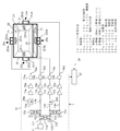
図1は、本発明の第1の実施の形態におけるマイクロ波処理装置の構成図である。
(Embodiment 1)
FIG. 1 is a configuration diagram of a microwave processing apparatus according to the first embodiment of the present invention.
図1において、マイクロ波発生部10は半導体素子を用いて構成した発振部11、発振部11の出力を4分配する2段構成からなる3つの電力分配部12a、12b、12c、分配部12b、12cのそれぞれの出力を後段の半導体素子を用いて構成した初段増幅部13a〜13dに導くマイクロ波伝送路14a〜14d、初段増幅部13a〜13dのそれぞれの出力をさらに増幅する半導体素子を用いて構成した主増幅部15a〜15d、主増幅部15a〜15dの出力をマイクロ波発生部10の出力部16a〜16dに導くマイクロ波伝送路17a〜17d、マイクロ波伝送路17a〜17dに挿入した電力検知部1
8a〜18dとで構成している。
In FIG. 1, a
8a to 18d.
また、本発明のマイクロ波処理装置は、被加熱物を収納する略直方体構造からなる加熱室19を有し、加熱室19は金属材料からなる左壁面20、右壁面21、底壁面22、上壁面23、奥壁面24および被加熱物を収納するために開閉する開閉扉(図示していない)から構成し、供給されるマイクロ波を内部に閉じ込めるように構成している。そして、マイクロ波発生部10の4つの出力が伝送されそのマイクロ波を加熱室19内に放射供給する給電部25a〜25dが加熱室19を構成する各壁面に配置されている。対向構成の左壁面20と右壁面21の略中央にはそれぞれ給電部25cと25d、上壁面23と底壁面22の略中央にはそれぞれ給電部25aと25bを対向して配置している。
In addition, the microwave processing apparatus of the present invention includes a heating chamber 19 having a substantially rectangular parallelepiped structure that accommodates an object to be heated, and the heating chamber 19 includes a
そして、各給電部25a〜25dは、加熱室壁面に設けた開口部251a〜251d、開口部251a〜251dを加熱室壁面の外部から覆うとともにそれぞれの開口部251a〜251dを終端側に配置した導波部252a〜252d、それぞれの導波部252a〜252dにマイクロ波発生部10の各出力を供給する供給部253a〜253dでもって構成している。開口部251a〜251dは、略矩形形状とし、対向配置の開口部251aと251b、および開口部251cと251dは、それぞれ略矩形形状の開口の長手開口方向を平行状態に配置している。また、開口部251aを配する上壁面23に直交して隣接する左右壁面に配置した開口部251cおよび251dは、開口の長手方向が直交状態に配置している。さらには、左右壁面20、21に配設した給電部25c、25dは、開口部251c、251dがそれぞれの給電部の供給部253c、253dに対して高さ方向に高い位置に配置している。なお、構成要素として加熱室19内へのマイクロ波の伝送効率を高めるために導波部252a〜252dの内部にインピーダンス整合素子を付帯させる場合もある。
And each electric power feeding
初段増幅部13a〜13dおよび主増幅部15a〜15dは、低誘電損失材料から構成した誘電体基板の片面に形成した導電体パターンにて回路を構成し、各増幅部の増幅素子である半導体素子を良好に動作させるべく各半導体素子の入力側と出力側にそれぞれ整合回路を配している。
The first
マイクロ波伝送路14a〜14d、17a〜17dは、誘電体基板の片面に設けた導電体パターンによって特性インピーダンスが略50Ωの伝送回路を形成している。
The
電力分配部12a、12b、12cは、それぞれ同一構造の3dBブランチラインカプラー構成とし、電力分配部12aを代表してその構成を説明する。電力分配部12aの各端子を121〜124とすると、端子121と端子122の間および端子123と端子124の間には特性インピーダンスが略50Ωでその電気長がλ/4(λは使用周波数帯の中央周波数の実効波長)からなるマイクロストリップ線路を配置し、端子121と端子123の間および端子122と端子124の間には特性インピーダンスが略35.35Ωで電気長λ/4のマイクロストリップ線路を配置し、さらに端子123には抵抗値が50Ωの電力終端器125を接続配置した構成からなる。この構成により、端子121に入力したマイクロ波信号は、端子122および端子124に2分配されて出力される。また、このとき端子122と端子124とから出力される信号は、端子122の出力信号の位相を基準にすると端子124から出力される信号は位相が90度遅れる。
The
この電力分配部を2段接続した構成により、発振部11の出力電力は、略1/4ずつ分配され、後続の初段増幅部13a〜13dに出力される。また、マイクロ波伝送路14bを伝送するマイクロ波信号を基準にするとマイクロ波伝送路14aおよび14cを伝送するマイクロ波信号は、位相が90度遅れた信号として伝送され、マイクロ波伝送路14dを伝送するマイクロ波信号は、位相が180度遅れた信号として伝送される。
With the configuration in which the power distribution units are connected in two stages, the output power of the
また、マイクロ波伝送路14aと14cにはそれぞれ位相可変部26a、26bを挿入している。この位相可変部26a、26bは、印加電圧に応じて容量が変化する容量可変素子を用いて構成し、位相可変範囲は、0度から略180度の範囲としている。
Further, phase
また、電力検知部18a〜18dは、加熱室19側からマイクロ波発生部10側にそれぞれ伝送するいわゆる反射波の電力を抽出するものであり、電力結合度をたとえば約40dBとし、反射電力の約1/10000の電力量を抽出する。この電力信号はそれぞれ、検波ダイオード(図示していない)で整流化しコンデンサ(図示していない)で平滑処理し、その出力信号を制御部27に入力させている。
The
制御部27は、使用者が直接入力する被加熱物の加熱条件(矢印28)あるいは加熱中に被加熱物の加熱状態から得られる加熱情報(矢印28)と電力検知部18a〜18dからの検知情報に基づいて、マイクロ波発生部10の構成要素である発振部11と初段増幅部13a〜13dと主増幅部15a〜15dのそれぞれに供給する駆動電力の制御や位相可変部26a、26bに供給する電圧を制御し、加熱室19内に収納された被加熱物を最適に加熱する。
The control unit 27 detects the heating conditions (arrow 28) obtained from the heating condition of the object to be heated (arrow 28) directly input by the user or the heating information (arrow 28) obtained from the heating state of the object to be heated and detection from the
また、マイクロ波発生部10には半導体素子の発熱を放熱させる放熱手段(図示していない)を配する。なお、加熱室19の底壁面22に設けた給電部25bを覆うとともに被加熱物を収納載置する低誘電損失材料からなる載置皿29を配する。
The
以上のように構成されたマイクロ波処理装置について、以下その動作、作用を説明する。 About the microwave processing apparatus comprised as mentioned above, the operation | movement and an effect | action are demonstrated below.
まず被加熱物を加熱室19に収納し、その加熱条件を操作部(図示していない)から入力し、加熱開始キーを押す。加熱開始信号を受けた制御部27の制御出力信号によりマイクロ波発生部10が動作を開始する。制御手段27は、駆動電源(図示していない)を動作させて発振部11に電力を供給する。この時、発振部11の初期の発振周波数は、たとえば2450MHzに設定する電圧信号を供給し、発振が開始する。
First, the object to be heated is stored in the heating chamber 19, the heating condition is input from the operation unit (not shown), and the heating start key is pressed. In response to the control output signal of the control unit 27 that has received the heating start signal, the
発振部11を動作させると、その出力は電力分配部12aにて略1/2分配され、後続の電力分配器12b、12cにてさらに略1/2分配され、4つのマイクロ波電力信号となる。以降、駆動電源を制御して初段増幅部を動作させ、次に主増幅部を動作させる。
When the
そしてそれぞれのマイクロ波電力信号は並列動作する増幅部13a〜13d、15a〜15d、電力検知部18a〜18dを経て出力部16a〜16dにそれぞれ出力される。そして、それぞれの出力は給電部25a〜25dに伝送され加熱室19内に放射される。このとき、給電部25bから放射されるマイクロ波信号の位相を基準にすると、給電部25aおよび給電部25cのマイクロ波信号は、略90度遅れた信号となり、給電部25dのマイクロ波信号は略180度遅れた信号となる。すなわち、隣接した給電部の間の位相差が略90度となるようにマイクロ波発生部10の出力をそれぞれの給電部に供給するように配置している。このときの各主増幅部はそれぞれ100W未満、たとえば50Wのマイクロ波電力を出力する。
And each microwave power signal is each output to the
加熱室19内に供給されるマイクロ波電力が被加熱物に100%吸収されると加熱室19からの反射電力は無しになるが、被加熱物の種類・形状・量が被加熱物を含む加熱室19の電気的特性を決定し、マイクロ波発生部10の出力インピーダンスと加熱室19のインピーダンスとに基づいて、加熱室19側からマイクロ波発生部10側に伝送する反射電力が生じる。
When 100% of the microwave power supplied into the heating chamber 19 is absorbed by the object to be heated, the reflected power from the heating chamber 19 is eliminated, but the type, shape, and amount of the object to be heated include the object to be heated. Based on the output impedance of the
電力結合器18a〜18dは、マイクロ波発生部10側に伝送する反射電力と結合し、その反射電力量に比例した信号を検出するものであり、その検出信号を受けた制御部27は、反射電力が極小値となる発振周波数の選択を行う。この周波数選択に対して、制御部27は、発振部の発振周波数を初期の2450MHzから0.1MHzピッチ(たとえば、10ミリ秒で1MHz)で低い周波数側に変化させ、周波数可変範囲の下限である2400MHzに到達すると1MHzピッチで周波数を高く変化させ、2450MHzに到達すると再び0.1MHzピッチで周波数可変範囲の上限である2500MHzまで高くする。この周波数可変の中で得られた反射電力が極小となる周波数とその周波数における反射電力に相当する信号を記憶する。そして、反射電力が極小をとる周波数群において反射電力に相当する信号が最も小さい周波数を選定し、発振部をその選定した周波数が発振するように制御するとともに発振出力を入力された加熱条件に対応した出力が得られるように制御する。これにより、各主増幅部はそれぞれ200Wから300Wのマイクロ波電力を出力する。
The
そして、それぞれの出力は給電部25a〜25dに伝送され加熱室19内に放射される。このとき、給電部25bから放射されるマイクロ波信号の位相を基準にすると、給電部25aおよび給電部25cのマイクロ波信号は、略90度遅れた信号となり、給電部25dのマイクロ波信号は略180度遅れた信号となる。すなわち、隣接した給電部の間の位相差が略90度となるようにマイクロ波発生部10の出力をそれぞれの給電部に供給するように配置している。
Each output is transmitted to the
また、略90度の倍数の位相差を形成に対して電力分配部に90度ハイブリッド分配器を用いることで、コンパクト形状で安定な等分配が実行でき、かつその電力分配部を複数段接続することで4分配や8分配を形成しても分配出力間の位相差は略90度が安定に形成できる。 In addition, by using a 90-degree hybrid distributor in the power distribution unit for forming a phase difference that is a multiple of about 90 degrees, a stable uniform distribution can be executed in a compact shape, and the power distribution units are connected in multiple stages. Thus, even if 4-distribution or 8-distribution is formed, the phase difference between the distribution outputs can be stably formed at approximately 90 degrees.
また、マイクロ波伝送路14aおよび14cにそれぞれ挿入した位相可変部26a、26bに印加する電圧を制御することで、対向および/または近接した給電部である25a、25b、25c、25dのそれぞれの位相差を同相にしたり逆相(180度差)にすることで、加熱室19内のマイクロ波の伝搬状態を時間的に変化させ、被加熱物の局所加熱の解消をし、加熱の均一化を促進することができる。
Further, by controlling the voltage applied to the phase
なお、本実施の形態においては、位相可変部は2つだけ挿入したが、最大ですべてのマイクロ波伝送路14a〜14dに挿入し、それぞれを個別にかつ時間的に制御することで、複数の給電部から放射されるマイクロ波の位相の組合せを変化させることでさらに均一加熱を促進させることができる。また、電力検知部18a〜18dの検知信号に基づいて、反射電力量が少なくなるように位相可変部への印加電圧を制御することで、加熱の効率を高くでき短時間加熱を図ることもできる。電力検知部が検知する反射電力量が所定の最大許容反射電力量を超える場合には、制御部27は発振出力を低下させるように発振部11あるいは増幅部13a〜13dおよび15a〜15dへの供給電力を低減させて、各半導体素子の熱破壊を回避させる。
In the present embodiment, only two phase variable sections are inserted. However, a plurality of phase variable sections are inserted into all the
そして、複数の給電部配置において少なくとも2つの給電部は、加熱室を構成する隣接した壁面(左壁面20と底壁面22、あるいは右壁面21と底壁面22の関係)に配置したことにより被加熱物に異なる2方向から直接的にマイクロ波を放射させることで厚みのある被加熱物などの加熱を促進できる。
In the arrangement of the plurality of power feeding parts, at least two power feeding parts are heated by being arranged on adjacent wall surfaces (the
また、複数の給電部配置において対向する壁面に設けた給電部のそれぞれの開口部から放射されるマイクロ波は開口部の平行状態の方向に垂直な方向に加熱室壁面をそれぞれ周
回しながら伝搬するので、それぞれ開口部から放射されたマイクロ波の偏波面は略平行となりそれぞれのマイクロ波のエネルギを被加熱物に集中させることができる。
In addition, the microwaves radiated from the openings of the power supply units provided on the opposing wall surfaces in the plurality of power supply unit arrangements propagate while circulating around the heating chamber wall surfaces in a direction perpendicular to the direction of the parallel state of the openings. Therefore, the polarization planes of the microwaves radiated from the openings are substantially parallel, and the energy of each microwave can be concentrated on the object to be heated.
また、複数の給電部において、加熱室を構成する隣接した壁面に配置される給電部の開口部を直交状態に配置した構成からなり、これにより隣接する給電部の開口部から放射されるマイクロ波の偏波面を直交状態にすることで互いの干渉を緩和し、それぞれの給電部から放射するマイクロ波のエネルギを効率よく被加熱物に供給させることができる。 Further, in the plurality of power supply units, the power supply unit openings arranged on the adjacent wall surfaces constituting the heating chamber are arranged in an orthogonal state, whereby microwaves radiated from the adjacent power supply unit openings By making the planes of polarization of each other orthogonal, the mutual interference can be mitigated, and the microwave energy radiated from each power feeding section can be efficiently supplied to the object to be heated.
さらに、加熱室の側壁面である左壁面20と右壁面21にそれぞれ配置した給電部の開口部は、導波部への供給部よりも高い位置に配置した構成からなり、これにより開口部から放射されるマイクロ波の伝搬方向を上壁面側に偏らせることができ、被加熱物の量・形状などの影響によるそれぞれの開口部から放射されるマイクロ波の偏向面の乱れを緩和し、マイクロ波エネルギをより効率よく被加熱物に供給させることができる。
Furthermore, the opening part of the power feeding part arranged on each of the
また、加熱室の側壁面である左壁面20と右壁面21にそれぞれに配置した給電部の開口部は、それぞれの側壁面の略中央に配置した構成からなり、これにより被加熱物の嵩高さの影響によるそれぞれの開口部から放射されるマイクロ波の偏向面の乱れを緩和し、マイクロ波エネルギをより効率よく被加熱物に供給させることができる。
Moreover, the opening part of the electric power feeding part arrange | positioned at the
さらに、電力分配部の出力を増幅部に伝送する複数の伝送路の少なくとも1つに位相可変部を配置したことにより、位相可変部を制御して対象の給電部から放射されるマイクロ波の位相を時間的に変化させることにより他の給電部から出力されるマイクロ波との位相差を時間的に変化させ加熱室内のマイクロ波分布を変化させて被加熱物の加熱の均一化をより促進させることができる。 Furthermore, by arranging the phase variable unit in at least one of the plurality of transmission paths for transmitting the output of the power distribution unit to the amplifier unit, the phase of the microwave radiated from the target power supply unit by controlling the phase variable unit By changing the time with time, the phase difference from the microwaves output from other power supply units is changed with time, and the microwave distribution in the heating chamber is changed to further promote uniform heating of the object to be heated. be able to.
(実施の形態2)
図2は本発明の第2の実施の形態におけるマイクロ波処理装置の構成図である。
(Embodiment 2)
FIG. 2 is a block diagram of a microwave processing apparatus according to the second embodiment of the present invention.
図2において、実施の形態1と同一部材あるいは同一機能部材は同一番号にて示すとともに説明は省略する。第2の実施の形態が実施の形態1と相違する点は、増幅部選択手段30を用いた点である。 In FIG. 2, the same members or the same function members as those in the first embodiment are denoted by the same reference numerals and the description thereof is omitted. The second embodiment is different from the first embodiment in that an amplification unit selection unit 30 is used.
すなわち図2において、マイクロ波発生部31は半導体素子を用いて構成した発振部11、発振部11の出力を2分配する電力分配部12a、電力分配部12aのそれぞれの出力を後続の増幅部選択手段30a、30bに導くマイクロ波伝送路32a、32b、増幅部選択手段30a、30bのそれぞれの切換端子301a〜301dと半導体素子を用いて構成した初段増幅部13a〜13dの入力端とを接続したマイクロ波伝送路33a〜33d、初段増幅部13a〜13dのそれぞれの出力をさらに増幅する半導体素子を用いて構成した主増幅部15a〜15d、主増幅部15a〜15dの出力をマイクロ波発生部31の出力部16a〜16dに導くマイクロ波伝送路17a〜17d、マイクロ波伝送路17a〜17dに挿入した電力検知部18a〜18dとで構成している。
That is, in FIG. 2, the microwave generation unit 31 includes an
また、被加熱物を収納する略直方体構造からなる加熱室19を有し、加熱室19は金属材料からなる左壁面20、右壁面21、底壁面22、上壁面23、奥壁面24および被加熱物を収納するために開閉する開閉扉(図示していない)から構成し、供給されるマイクロ波を内部に閉じ込めるように構成している。そして、マイクロ波発生部31の4つの出力部にそれぞれ接続された給電部25a〜25dが加熱室19を構成する各壁面に配置されている。対向構成の左壁面20と右壁面21の略中央にはそれぞれ給電部25cと25d、上壁面23と底壁面22の略中央にはそれぞれ給電部25aと25bを配置している。そして、増幅部切換手段30aによって給電部25aと給電部25dとが切換選択され
る。また、増幅部切換手段30bによって給電部25bと給電部25cとが切換選択される。
Moreover, it has the heating chamber 19 which consists of a substantially rectangular parallelepiped structure which accommodates to-be-heated material, and the heating chamber 19 is the
発振部11の出力電力は、電力分配部12aにより略1/2ずつ分配され、マイクロ波伝送路32a、32bを伝送して後続の増幅部選択手段30a、30bに入力する。増幅部選択手段30a、30bは、後続される増幅部13a〜13d(および15a〜15d)の中でマイクロ波を伝送する増幅部を選択するものである。そして、増幅部選択手段30a、30bを動作制御することによりマイクロ波信号が伝送するマイクロ波伝送路33a〜33dがそれぞれ選択され、選択されたマイクロ波伝送路に接続した増幅部に駆動電力を供給することでマイクロ波信号は増幅され、増幅したマイクロ波電力信号が選択された増幅部に接続した給電部から加熱室19内に放射供給される。
The output power of the
このとき、マイクロ波伝送路32aを伝送するマイクロ波信号を基準にするとマイクロ波伝送路32bを伝送するマイクロ波信号は、位相が90度遅れた信号として伝送される。そして最終的に加熱室19内に放射されるマイクロ波は、給電部25aまたは給電部25bから放射されるマイクロ波の位相を基準にすると給電部25cまたは給電部25dから放射されるマイクロ波の位相が略90度遅れた信号となって放射される。
At this time, based on the microwave signal transmitted through the microwave transmission path 32a, the microwave signal transmitted through the microwave transmission path 32b is transmitted as a signal whose phase is delayed by 90 degrees. And the microwave finally radiated | emitted in the heating chamber 19 is based on the phase of the microwave radiated | emitted from the electric
また、マイクロ波伝送路32aには位相可変部26を挿入している。この位相可変部26は、印加電圧に応じて容量が変化する容量可変素子を用いて構成し、位相可変範囲は、0度から略180度の範囲としている。 Further, the phase variable unit 26 is inserted in the microwave transmission path 32a. The phase variable unit 26 is configured using a capacitance variable element whose capacitance changes according to the applied voltage, and the phase variable range is a range from 0 degrees to about 180 degrees.
以上のように構成されたマイクロ波処理装置について、以下その動作と作用を説明する。 About the microwave processing apparatus comprised as mentioned above, the operation | movement and an effect | action are demonstrated below.
被加熱物の加熱開始時の発振周波数の選択に係る諸動作は、実施の形態1と同様であり、その動作説明は省略する。 Various operations related to selection of the oscillation frequency at the start of heating of the object to be heated are the same as those in the first embodiment, and the description of the operation is omitted.
被加熱物を加熱室19に収納し、その加熱条件を操作部(図示していない)から入力し、加熱開始キーを押すことで、加熱条件や加熱開始信号(図2の34)を受けた制御部27の制御出力信号によりマイクロ波発生部31が動作を開始する。制御部27は、入力された加熱条件に基づいて増幅部選択手段30a、30bを制御し、加熱開始時に動作させる増幅部を決定する。その後、発振部11に駆動電力を供給し、所望の発振周波数のマイクロ波を発振させる。以降、増幅部選択手段30a、30bが選択した増幅部の初段増幅部を動作させ、次に主増幅部を動作させる。
The object to be heated is stored in the heating chamber 19, the heating condition is input from the operation unit (not shown), and the heating start key is pressed to receive the heating condition and the heating start signal (34 in FIG. 2). The microwave generation unit 31 starts to operate according to the control output signal of the control unit 27. The control unit 27 controls the amplification unit selection means 30a and 30b based on the input heating condition, and determines the amplification unit to be operated at the start of heating. Thereafter, driving power is supplied to the
これにより、各主増幅部はそれぞれ200Wから500Wのマイクロ波電力を位相差90度でもって出力する。そして選択された増幅部に接続された給電部から被加熱物が収納された加熱室19内にマイクロ波が供給放射される。たとえば、加熱初期に選択されマイクロ波を放射する給電部が右壁面21に配置した給電部25dと底壁面22に配置した給電部25bとした場合、これらの給電部から放射されるマイクロ波の位相差は略90度(たとえば給電部25bの信号を基準にすると給電部25dの信号が略90度遅れた状態)であり、加熱室19の略中央部から右壁面21側にマイクロ波の電界集中領域が形成される。加熱室19に形成された電界集中領域により、被加熱物が加熱室19の略中央に収納された場合には、被加熱物の略中央から右寄りが強く加熱される。
As a result, each main amplification section outputs microwave power of 200 W to 500 W with a phase difference of 90 degrees. Then, microwaves are supplied and radiated from the power supply unit connected to the selected amplification unit into the heating chamber 19 in which the object to be heated is stored. For example, when the power feeding unit selected at the initial stage of heating is a
そして制御部27は、被加熱物の加熱の均一化を図るために、適当な時間周期あるいは被加熱物の温度分布情報に基づいて、動作させる増幅部を切り替える制御信号をマイクロ波発生部31に出力する。この制御信号により、切り替え対象の増幅部への駆動電力を停止し増幅部選択手段を作動させて動作させる増幅部の切り替えをする。切り替えが終わる
と対象の増幅部に電力を供給してその増幅部を動作させる。
Then, the control unit 27 sends a control signal to the microwave generation unit 31 for switching the amplification unit to be operated based on an appropriate time period or temperature distribution information of the heated object in order to achieve uniform heating of the heated object. Output. By this control signal, the driving power to the switching target amplification unit is stopped, and the amplification unit to be operated is switched by operating the amplification unit selection means. When the switching is completed, power is supplied to the target amplification unit to operate the amplification unit.
この一連の動作をたとえば、給電部25dを給電部25cに切り替える場合に当てはめて説明する。給電部25dを給電部25cへの切り替えは、被加熱物の略中央から左寄りの加熱を促進する目的で実施する。
This series of operations will be described, for example, when the
そして、たとえば被加熱物の温度分布情報としての被加熱物の表面温度分布において、被加熱物の略中央から左寄りの領域における表面温度の最低温度が右寄りの領域における最高表面温度に比べて10℃以上の差に達した場合に切り替え指令を制御部27が出力する。 For example, in the surface temperature distribution of the object to be heated as the temperature distribution information of the object to be heated, the lowest surface temperature in the region on the left side from the approximate center of the object to be heated is 10 ° C. compared to the maximum surface temperature in the region on the right side. When the above difference is reached, the control unit 27 outputs a switching command.
この切り替え指令に基づいて、初段増幅部13dおよび主増幅部15dに供給している駆動電力を停止する。そして、増幅部選択手段30bを制御し、コモン端子を端子301cと接続する。その後、初段増幅部13cおよび主増幅部15cに順次駆動電力を供給する。この一連の制御動作により給電部25cからマイクロ波が加熱室19内に供給される。
Based on this switching command, the drive power supplied to the
左壁面20の給電部25cおよび底壁面22の給電部25bの両者からのマイクロ波供給により、被加熱物は、その略中央より左寄りの領域が強く加熱され始める。
Due to the microwave supply from both the
この状態を継続する中で、被加熱物の略中央より左寄りの領域の加熱に伴う表面温度上昇が芳しくない場合には、底壁面22に配置した給電部25bからのマイクロ波給電を給電部25aからのマイクロ波給電に切り替える。
In continuing this state, when the surface temperature rise due to the heating of the region to the left of the substantially center of the object to be heated is not good, the microwave power feeding from the
この切り替え制御は、制御対象となる増幅部および増幅部選択手段が異なるが上述した給電部25dから給電部25cへの切り替え制御内容に準じるものである。
This switching control is based on the above-described switching control content from the
以上の一連の切り替え制御は、被加熱物の表面温度分布情報に基づいて、加熱中に適宜実施するものである。 The series of switching control described above is appropriately performed during heating based on the surface temperature distribution information of the object to be heated.
また、マイクロ波伝送路32aに挿入した位相可変部26に印加する電圧を制御することで、動作中の2つの給電部から放射されるマイクロ波の位相差を同相にしたり逆相(180度差)にすることで、加熱室19内のマイクロ波の伝搬状態を時間的に変化させ、被加熱物の局所加熱の解消をし、加熱の均一化をさらに促進することができる。 Further, by controlling the voltage applied to the phase variable section 26 inserted in the microwave transmission path 32a, the phase difference of the microwaves radiated from the two power feeding sections in operation can be made in-phase or reversed (180-degree difference). ), The propagation state of the microwave in the heating chamber 19 can be temporally changed, the local heating of the object to be heated can be eliminated, and the uniform heating can be further promoted.
そして、被加熱物の表面温度検出手段の検知信号や手動入力された加熱時間情報に基づいて、加熱が終了制御される。 Then, heating is controlled to end based on the detection signal of the surface temperature detection means of the article to be heated and the manually input heating time information.
以上に説明した実施の形態2によれば、増幅部選択手段を制御して加熱室内にマイクロ波を供給する位置を選択することで、被加熱物の特定部分の加熱を促進させたり、またマイクロ波を供給する位置を時間的に選択切換することで被加熱物全体を所望の状態に加熱することができる。 According to the second embodiment described above, the amplification unit selecting means is controlled to select the position where the microwave is supplied into the heating chamber, so that heating of a specific part of the object to be heated is promoted. The entire object to be heated can be heated to a desired state by selectively switching the position where the waves are supplied.
また、電力分配部の出力と増幅部選択手段との間に位相可変部を配置することで、位相可変部を制御して対象の給電部から放射されるマイクロ波の位相を時間的に変化させることにより他の給電部から出力されるマイクロ波との位相差を時間的に変化させ加熱室内のマイクロ波分布を変化させて被加熱物の加熱の均一化をより促進させることができる。 Also, by arranging the phase variable unit between the output of the power distribution unit and the amplification unit selecting means, the phase variable unit is controlled to change the phase of the microwave radiated from the target power supply unit with time. Accordingly, the phase difference from the microwaves output from the other power feeding units can be changed temporally to change the microwave distribution in the heating chamber, thereby further promoting the uniform heating of the object to be heated.
また、複数の給電部配置において、加熱室を構成する対向した壁面に配置した一対の給電部に対応する増幅部のいずれか一方を増幅部選択手段が選択する構成としたことにより
、被加熱物の種類・大きさ・量に応じて対向配置の給電部のいずれか一方からマイクロ波を放射することで給電部に近い側の被加熱物領域を強く加熱することができる。これを利用して、受熱効率の異なる異種の被加熱物を同時に均一に昇温させることが可能にできる。対向壁面として、加熱室の左右壁面あるいは上下壁面が実用価値が大きい。
Further, in the plurality of power feeding unit arrangements, the amplification unit selecting means selects one of the amplification units corresponding to the pair of power feeding units arranged on the opposing wall surfaces constituting the heating chamber. By radiating microwaves from either one of the opposingly arranged power supply units according to the type, size, and quantity of the object, the heated object region near the power supply unit can be strongly heated. By utilizing this, it is possible to raise the temperature of different types of heated objects having different heat receiving efficiencies simultaneously and uniformly. As the opposing wall surface, the right and left wall surfaces or the upper and lower wall surfaces of the heating chamber have great practical value.
さらに、複数の給電部配置において、加熱室を構成する同一壁面に配置した一対の給電部に対応する増幅部のいずれか一方を増幅部選択手段が選択する構成としたことにより、被加熱物の種類・大きさ・量に応じて対向配置の給電部のいずれか一方からマイクロ波を放射することで給電部に近い側の被加熱物領域を強く加熱することができる。これを利用して、受熱効率の異なる異種の被加熱物を同時に均一に昇温させることが可能にできる。同一壁面として、加熱室の底壁面が実用価値が大きい。 Further, in the plurality of power feeding unit arrangements, the amplification unit selecting means selects one of the amplification units corresponding to the pair of power feeding units arranged on the same wall surface constituting the heating chamber. Depending on the type, size, and quantity, the heated object region on the side close to the power feeding unit can be strongly heated by radiating microwaves from either one of the power feeding units arranged oppositely. By utilizing this, it is possible to raise the temperature of different types of heated objects having different heat receiving efficiencies simultaneously and uniformly. As the same wall surface, the bottom wall surface of the heating chamber has great practical value.
さらにまた、複数の給電部配置において、同一壁面に配置した一対の給電部と、対向した壁面に配置した一対の給電部とを有し、同一壁面への配置は対向した壁面の対向方向としたことにより、対向配置の給電部と同一壁面配置の給電部との放射方向は直交する方向となり、対向配置の給電部のひとつからのマイクロ波放射を継続しながら、同一壁面配置の給電部のマイクロ波放射を時間的に選択切換することで被加熱物の加熱の均一化を促進できる。特に加熱室形状が横長の直方体構造のものに適用することで実用価値を高くできる。 Furthermore, in the plurality of power feeding unit arrangements, the power supply unit has a pair of power feeding units arranged on the same wall surface and a pair of power feeding units arranged on the opposite wall surfaces, and the arrangement on the same wall surface is set to be a facing direction of the opposed wall surfaces. As a result, the radiation direction of the power supply unit arranged in the opposite direction and the power supply unit arranged in the same wall surface are orthogonal to each other, and the microwave of the power supply unit arranged in the same wall surface is maintained while continuing the microwave radiation from one of the power supply units arranged in the opposite direction. It is possible to promote uniform heating of the object to be heated by selectively switching the wave radiation in terms of time. In particular, the practical value can be increased by applying the heating chamber to a horizontally long rectangular parallelepiped structure.
以上のように、本発明にかかるマイクロ波処理装置はマイクロ波を放射する機能を有した複数の給電部を加熱室を構成する壁面に最適に配置しそれぞれの給電部からの放射方向を最適化するとともにマイクロ波を放射する給電部を切り替え制御したり動作中の給電部間のマイクロ波の位相差を変化させる装置を提供できるので、電子レンジで代表されるような誘電加熱を利用した加熱装置や生ゴミ処理機、あるいは半導体製造装置であるプラズマ電源のマイクロ波電源などの用途にも適用できる。 As described above, the microwave processing apparatus according to the present invention optimizes the radiation direction from each power supply unit by optimally arranging a plurality of power supply units having a function of radiating microwaves on the wall surface constituting the heating chamber. In addition, it is possible to provide a device that changes the microwave phase difference between the power supply units that are operating while switching the power supply unit that radiates the microwaves. Therefore, a heating device that uses dielectric heating as represented by a microwave oven It can also be applied to uses such as a microwave power source of a plasma power source that is a garbage processing machine or a semiconductor manufacturing apparatus.
10、31 マイクロ波発生部
11 発振部
12a、12b、12c 電力分配部
13a〜13d、15a〜15d 増幅部
16a〜16d 複数の出力部
19 加熱室
20 左壁面(対向した壁面のひとつ)
21 右壁面(対向した壁面のひとつ)
22 底壁面(他の対向した壁面のひとつ)
23 上壁面(他の対向した壁面のひとつ)
25a〜25d 給電部
251a〜251d 開口部
252a〜252d 導波部
253a〜253d 供給部
26、26a、26b 位相可変部
DESCRIPTION OF
21 Right wall (one of the opposite walls)
22 Bottom wall (one of the other facing walls)
23 Upper wall (one of the other facing walls)
25a to
Claims (6)
Priority Applications (1)
| Application Number | Priority Date | Filing Date | Title |
|---|---|---|---|
| JP2007106789A JP4992525B2 (en) | 2007-04-16 | 2007-04-16 | Microwave processing equipment |
Applications Claiming Priority (1)
| Application Number | Priority Date | Filing Date | Title |
|---|---|---|---|
| JP2007106789A JP4992525B2 (en) | 2007-04-16 | 2007-04-16 | Microwave processing equipment |
Publications (2)
| Publication Number | Publication Date |
|---|---|
| JP2008269794A JP2008269794A (en) | 2008-11-06 |
| JP4992525B2 true JP4992525B2 (en) | 2012-08-08 |
Family
ID=40049072
Family Applications (1)
| Application Number | Title | Priority Date | Filing Date |
|---|---|---|---|
| JP2007106789A Expired - Fee Related JP4992525B2 (en) | 2007-04-16 | 2007-04-16 | Microwave processing equipment |
Country Status (1)
| Country | Link |
|---|---|
| JP (1) | JP4992525B2 (en) |
Families Citing this family (11)
| Publication number | Priority date | Publication date | Assignee | Title |
|---|---|---|---|---|
| EP2477455B1 (en) * | 2009-09-07 | 2020-03-04 | Panasonic Corporation | Microwave heating device |
| EP2480047B1 (en) * | 2009-09-16 | 2014-04-16 | Panasonic Corporation | Microwave heating device |
| CN103851661B (en) * | 2012-12-06 | 2016-08-17 | 广东美的厨房电器制造有限公司 | Semiconductor microwave oven |
| EP3151636B1 (en) * | 2014-05-28 | 2022-01-05 | Guangdong Midea Kitchen Appliances Manufacturing Co., Ltd. | Semiconductor microwave oven and semiconductor microwave source thereof |
| CN104879798B (en) * | 2015-05-05 | 2017-07-07 | 昆明理工大学 | A kind of micro-wave oven for quickly heating weak wave absorbtion material |
| KR101816214B1 (en) * | 2017-06-13 | 2018-01-08 | 김기중 | Multiple antennas for oven capable of uniform heating and oven using the same |
| PL3448121T3 (en) * | 2017-08-23 | 2021-06-14 | Vorwerk & Co. Interholding Gmbh | Microwave feed-in device on a microwave oven |
| JP7019702B2 (en) * | 2017-08-25 | 2022-02-15 | シャープ株式会社 | Cooker |
| JP7019703B2 (en) * | 2017-08-25 | 2022-02-15 | シャープ株式会社 | Cooker |
| EP3917284B1 (en) * | 2018-01-31 | 2022-02-23 | Midea Group Co., Ltd. | Microwave cooking apparatus, control method and storage medium |
| CN111372343A (en) * | 2018-12-26 | 2020-07-03 | 财团法人工业技术研究院 | Distributed microwave phase control method |
Family Cites Families (4)
| Publication number | Priority date | Publication date | Assignee | Title |
|---|---|---|---|---|
| JPS56132793A (en) * | 1980-03-19 | 1981-10-17 | Hitachi Netsu Kigu Kk | High frequency heater |
| JPS60138897A (en) * | 1983-12-26 | 1985-07-23 | 松下電器産業株式会社 | High frequency heater |
| JP2000357583A (en) * | 1999-06-15 | 2000-12-26 | Mitsubishi Electric Corp | Microwave oven |
| JP3960612B2 (en) * | 2004-06-25 | 2007-08-15 | 島田理化工業株式会社 | Microwave irradiation processing equipment |
-
2007
- 2007-04-16 JP JP2007106789A patent/JP4992525B2/en not_active Expired - Fee Related
Also Published As
| Publication number | Publication date |
|---|---|
| JP2008269794A (en) | 2008-11-06 |
Similar Documents
| Publication | Publication Date | Title |
|---|---|---|
| JP4992525B2 (en) | Microwave processing equipment | |
| JP4940922B2 (en) | Microwave processing equipment | |
| JP5167678B2 (en) | Microwave processing equipment | |
| JP5104048B2 (en) | Microwave processing equipment | |
| CN101743778B (en) | Microwave heating device | |
| JP5280372B2 (en) | Microwave heating device | |
| JP5142364B2 (en) | Microwave processing equipment | |
| JP5588989B2 (en) | Microwave heating device | |
| JP5239229B2 (en) | Microwave heating device | |
| KR20110057134A (en) | Microwave heating device | |
| JP2009259511A (en) | Microwave processing equipment | |
| JP5217882B2 (en) | Microwave processing equipment | |
| JP5645168B2 (en) | Microwave heating device | |
| JP2009252346A5 (en) | ||
| JP4839994B2 (en) | Microwave equipment | |
| JP5127038B2 (en) | High frequency processing equipment | |
| JP5169255B2 (en) | Microwave processing equipment | |
| JP2009238402A (en) | Microwave processor | |
| JP5217993B2 (en) | Microwave processing equipment | |
| JP2008146966A (en) | Microwave generation device and microwave heating apparatus | |
| JP2010073383A (en) | Microwave heating apparatus | |
| JP2008060016A (en) | Microwave utilization device | |
| JP5195008B2 (en) | Microwave heating device | |
| JP5217881B2 (en) | Microwave processing equipment | |
| JP5169254B2 (en) | Microwave processing equipment |
Legal Events
| Date | Code | Title | Description |
|---|---|---|---|
| A621 | Written request for application examination |
Free format text: JAPANESE INTERMEDIATE CODE: A621 Effective date: 20100323 |
|
| RD01 | Notification of change of attorney |
Free format text: JAPANESE INTERMEDIATE CODE: A7421 Effective date: 20100413 |
|
| A977 | Report on retrieval |
Free format text: JAPANESE INTERMEDIATE CODE: A971007 Effective date: 20111007 |
|
| A131 | Notification of reasons for refusal |
Free format text: JAPANESE INTERMEDIATE CODE: A131 Effective date: 20111018 |
|
| A521 | Written amendment |
Free format text: JAPANESE INTERMEDIATE CODE: A523 Effective date: 20111213 |
|
| TRDD | Decision of grant or rejection written | ||
| A01 | Written decision to grant a patent or to grant a registration (utility model) |
Free format text: JAPANESE INTERMEDIATE CODE: A01 Effective date: 20120410 |
|
| A01 | Written decision to grant a patent or to grant a registration (utility model) |
Free format text: JAPANESE INTERMEDIATE CODE: A01 |
|
| A61 | First payment of annual fees (during grant procedure) |
Free format text: JAPANESE INTERMEDIATE CODE: A61 Effective date: 20120423 |
|
| FPAY | Renewal fee payment (event date is renewal date of database) |
Free format text: PAYMENT UNTIL: 20150518 Year of fee payment: 3 |
|
| R151 | Written notification of patent or utility model registration |
Ref document number: 4992525 Country of ref document: JP Free format text: JAPANESE INTERMEDIATE CODE: R151 |
|
| FPAY | Renewal fee payment (event date is renewal date of database) |
Free format text: PAYMENT UNTIL: 20150518 Year of fee payment: 3 |
|
| LAPS | Cancellation because of no payment of annual fees |