JP4985996B2 - Scribing apparatus, and substrate cutting apparatus and method using the same - Google Patents
Scribing apparatus, and substrate cutting apparatus and method using the same Download PDFInfo
- Publication number
- JP4985996B2 JP4985996B2 JP2009111199A JP2009111199A JP4985996B2 JP 4985996 B2 JP4985996 B2 JP 4985996B2 JP 2009111199 A JP2009111199 A JP 2009111199A JP 2009111199 A JP2009111199 A JP 2009111199A JP 4985996 B2 JP4985996 B2 JP 4985996B2
- Authority
- JP
- Japan
- Prior art keywords
- scribe
- unit
- mother substrate
- substrate
- mother
- Prior art date
- Legal status (The legal status is an assumption and is not a legal conclusion. Google has not performed a legal analysis and makes no representation as to the accuracy of the status listed.)
- Active
Links
- 239000000758 substrate Substances 0.000 title claims description 269
- 238000000034 method Methods 0.000 title claims description 60
- 238000005520 cutting process Methods 0.000 title claims description 54
- 230000008569 process Effects 0.000 claims description 40
- 239000010409 thin film Substances 0.000 claims description 8
- 239000004973 liquid crystal related substance Substances 0.000 claims description 7
- 238000012546 transfer Methods 0.000 description 20
- 230000008878 coupling Effects 0.000 description 8
- 238000010168 coupling process Methods 0.000 description 8
- 238000005859 coupling reaction Methods 0.000 description 8
- 238000003825 pressing Methods 0.000 description 4
- 230000010365 information processing Effects 0.000 description 3
- 238000003780 insertion Methods 0.000 description 3
- 230000037431 insertion Effects 0.000 description 3
- 238000010586 diagram Methods 0.000 description 2
- 239000010432 diamond Substances 0.000 description 2
- 230000001678 irradiating effect Effects 0.000 description 2
- 230000000712 assembly Effects 0.000 description 1
- 238000000429 assembly Methods 0.000 description 1
- 239000000470 constituent Substances 0.000 description 1
- 229910003460 diamond Inorganic materials 0.000 description 1
- 238000005304 joining Methods 0.000 description 1
- 238000004519 manufacturing process Methods 0.000 description 1
- 238000012986 modification Methods 0.000 description 1
- 230000004048 modification Effects 0.000 description 1
- 230000000149 penetrating effect Effects 0.000 description 1
- 238000010791 quenching Methods 0.000 description 1
- 230000000171 quenching effect Effects 0.000 description 1
Images


Classifications
-
- Y—GENERAL TAGGING OF NEW TECHNOLOGICAL DEVELOPMENTS; GENERAL TAGGING OF CROSS-SECTIONAL TECHNOLOGIES SPANNING OVER SEVERAL SECTIONS OF THE IPC; TECHNICAL SUBJECTS COVERED BY FORMER USPC CROSS-REFERENCE ART COLLECTIONS [XRACs] AND DIGESTS
- Y02—TECHNOLOGIES OR APPLICATIONS FOR MITIGATION OR ADAPTATION AGAINST CLIMATE CHANGE
- Y02P—CLIMATE CHANGE MITIGATION TECHNOLOGIES IN THE PRODUCTION OR PROCESSING OF GOODS
- Y02P40/00—Technologies relating to the processing of minerals
- Y02P40/50—Glass production, e.g. reusing waste heat during processing or shaping
- Y02P40/57—Improving the yield, e-g- reduction of reject rates
Landscapes
- Re-Forming, After-Treatment, Cutting And Transporting Of Glass Products (AREA)
- Processing Of Stones Or Stones Resemblance Materials (AREA)
- Liquid Crystal (AREA)
- Chemical & Material Sciences (AREA)
- Engineering & Computer Science (AREA)
- Materials Engineering (AREA)
- Organic Chemistry (AREA)
Description
本発明は、フラットパネルディスプレイパネルの製造に用いられる装置及び方法に関し、より詳しくは、複数の単位基板が形成された母基板にスクライブラインを形成するスクライブ装置、そしてこれを用いて母基板を切断する装置及び方法に関する。 The present invention relates to an apparatus and method used for manufacturing a flat panel display panel, and more particularly, a scribing apparatus that forms a scribe line on a mother board on which a plurality of unit boards are formed, and a mother board is cut using the scribing apparatus. The present invention relates to an apparatus and a method.
最近、情報処理機器は、多様な形態の機能とより速くなった情報処理速度を有するように急速に発展しつつある。このような情報処理機器は、稼働した情報を表示するディスプレイを有する。従来では、ディスプレイとして主にブラウン管(CathodeRayTube)モニターが使用されたが、最近では、軽くかつ空間を小さく占める薄膜トランジスタ−液晶ディスプレイ(ThinFilmTransistor−LiquidCrystalDisplayPanel)又は有機ダイオードディスプレイ(OrganicLightEmittingDiodesdisplay)のようなフラットパネルディスプレイの使用が増大している。 Recently, information processing devices are rapidly developing to have various forms of functions and faster information processing speeds. Such an information processing device has a display for displaying information on operation. Conventionally, a cathode ray tube monitor has been mainly used as a display. Recently, a thin and thin space thin film transistor-liquid crystal display (ThinFilmTransistor-Liquid Crystal Display Panel) or an organic diode display (Organic Light Emitting Spatio display panel) is used. Use is increasing.
一般に、フラットパネルディスプレイなどに用いられるパネルは、通常脆性基板を利用して製作され、パネルは、一枚で構成された単板基板と2枚の基板が接合された接合基板とに大別される。 In general, a panel used for a flat panel display or the like is usually manufactured by using a brittle substrate, and the panel is roughly divided into a single plate substrate constituted by one piece and a bonded substrate obtained by joining two substrates. The
接合基板は、携帯電話の液晶表示器用のパネルのように小型なものから、テレビやディスプレイなどのパネルのような大型まで、多様な大きさに加工されて使用されるため、大型の母基板から所定の大きさの単位基板に切断されて各々のパネルとして利用される。
母基板を切断する方法には、レーザビームを利用して切断する方法、又は微細なダイヤモンドが嵌められているスクライブホイール(ScribeWheel)を利用して切断する方法がある。
Bonded substrates are processed and used in a variety of sizes, from small ones such as panels for mobile phone liquid crystal displays to large ones such as panels for televisions and displays. It is cut into unit substrates of a predetermined size and used as each panel.
As a method of cutting the mother substrate, there are a method of cutting using a laser beam, and a method of cutting using a scribe wheel (Scribe Wheel) in which fine diamonds are fitted.
レーザビームを利用して母基板を切断する方法は、母基板の切断予定線に沿ってスクライブ用レーザビームを照射してスクライブラインを形成し、加熱したスクライブラインを急冷させるスクライブ工程と、スクライブラインに沿ってブレイク用レーザビームを照射して母基板を単位基板に切断するブレイク工程からなる。 A method of cutting a mother substrate using a laser beam includes a scribing step of forming a scribe line by irradiating a scribe laser beam along a planned cutting line of the mother substrate, and quenching the heated scribe line, and a scribe line A break process of cutting a mother substrate into unit substrates by irradiating a laser beam for break along
スクライブホイールを利用して母基板を切断する方法は、スクライブホイールを母基板の切断予定線に接触した後、切断予定線に沿って所定の深さのスクライブライン(ScribeLine)を形成するスクライブ工程と、母基板に物理的な衝撃を加えてスクライブラインに沿ってクラック(Crack)が伝播するようにすることによって、母基板を単位基板に切断するブレイク工程からなる。 A method of cutting a mother substrate using a scribe wheel includes a scribing step of forming a scribe line (ScribeLine) having a predetermined depth along the planned cutting line after contacting the scribe wheel with the planned cutting line of the mother substrate. The method includes a breaking process of cutting the mother substrate into unit substrates by applying a physical impact to the mother substrate so that cracks propagate along the scribe lines.
本発明の目的は、母基板の上面と下面の方向性を維持した状態で、母基板の上下両面のうち何れか一面にスクライブラインを形成し、順次に他の一面にスクライブラインを形成できるスクライブ装置、そしてこれを用いた基板切断装置及び方法を提供することにある。
本発明の目的はこれに制限されず、言及していないまた他の目的は、以下の記載より当業者に明確に理解されることができるはずである。
An object of the present invention is to form a scribe line on one of the upper and lower surfaces of the mother substrate and maintain a scribe line on the other surface in order while maintaining the orientation of the upper and lower surfaces of the mother substrate. An apparatus, and a substrate cutting apparatus and method using the apparatus.
The object of the present invention is not limited thereto, and other objects not mentioned can be clearly understood by those skilled in the art from the following description.
前記課題を達成するため本発明によるスクライブ装置は、複数個の単位基板が形成された母基板を単位基板に分離するためのスクライブ工程を実行する装置において、前記母基板の上面と下面のうち何れか一面にスクライブラインを形成する第1スクライブ部と、上面と下面の方向性が維持された状態で、前記第1スクライブ部から移送される前記母基板の他の一面にスクライブラインを形成する第2スクライブ部を含むことを特徴とする。 In order to achieve the above object, a scribing apparatus according to the present invention is an apparatus for performing a scribing process for separating a mother substrate on which a plurality of unit substrates are formed into unit substrates. A first scribe portion that forms a scribe line on one surface, and a scribe line that is formed on the other surface of the mother substrate transferred from the first scribe portion in a state in which the orientation of the upper surface and the lower surface is maintained. It includes 2 scribe parts.
上述のような構成を有する本発明によるスクライブ装置において、前記第1スクライブ部は、前記母基板の下面を支持する第1支持部材と、前記母基板の上面にスクライブラインを形成する第1スクライブユニットと、を含み、前記第2スクライブ部は前記母基板の上面を支持する第2支持部材と、前記母基板の下面にスクライブラインを形成する第2スクライブユニットと、を含むことができる。 In the scribing apparatus according to the present invention having the above-described configuration, the first scribe unit includes a first support member that supports a lower surface of the mother substrate and a first scribe unit that forms a scribe line on the upper surface of the mother substrate. The second scribe part may include a second support member that supports the upper surface of the mother substrate and a second scribe unit that forms a scribe line on the lower surface of the mother substrate.
前記第1スクライブ部は、前記母基板の上面を支持する第1支持部材と、前記母基板の下面にスクライブラインを形成する第1スクライブユニットと、を含み、前記第2スクライブ部は、前記母基板の下面を支持する第2支持部材と、前記母基板の上面にスクライブラインを形成する第2スクライブユニットと、を含むことができる。 The first scribe portion includes a first support member that supports an upper surface of the mother substrate and a first scribe unit that forms a scribe line on the lower surface of the mother substrate, and the second scribe portion includes the mother scriber. A second support member that supports the lower surface of the substrate and a second scribe unit that forms a scribe line on the upper surface of the mother substrate may be included.
前記母基板は、フラットパネルディスプレイ基板であり得る。 The mother substrate may be a flat panel display substrate.
前記フラットパネルディスプレイ基板は、カラーフィルタ基板と薄膜トランジスタ基板とが上下方向に積層された薄膜トランジスタ−液晶ディスプレイ(TFT−LCD)用パネルであり得る。 The flat panel display substrate may be a thin film transistor-liquid crystal display (TFT-LCD) panel in which a color filter substrate and a thin film transistor substrate are vertically stacked.
前記課題を達成するために本発明による基板切断装置は、複数個の単位基板が形成された母基板がロードされるロード部と、前記ロード部から伝達された前記母基板の上面と下面のうち何れか一面にスクライブラインを形成する第1スクライブ部と、上面と下面の方向性が維持された状態で、前記第1スクライブ部から移送される前記母基板の他の一面にスクライブラインを形成する第2スクライブ部と、前記母基板に生成されたスクライブラインに沿って前記母基板を単位基板に分離するブレイク部と、分離された前記単位基板をアンロードするアンロード部と、を含むことを特徴とする。 In order to achieve the above object, a substrate cutting apparatus according to the present invention includes a load unit on which a mother substrate having a plurality of unit substrates is loaded, and an upper surface and a lower surface of the mother substrate transmitted from the load unit. A scribe line is formed on the other surface of the mother substrate transferred from the first scribe portion in a state where the orientation of the upper surface and the lower surface is maintained while the first scribe portion forms a scribe line on any one surface. A second scribe unit; a break unit that separates the mother substrate into unit substrates along a scribe line generated on the mother substrate; and an unload unit that unloads the separated unit substrates. Features.
上述のような構成を有する本発明による基板切断装置において、前記第1スクライブ部は前記母基板の下面を支持する第1支持部材と、前記母基板の上面にスクライブラインを形成する第1スクライブユニットと、を含み、前記第2スクライブ部は前記母基板の上面を支持する第2支持部材と、前記母基板の下面にスクライブラインを形成する第2スクライブユニットと、を含むことができる。 In the substrate cutting apparatus according to the present invention having the above-described configuration, the first scribe unit includes a first support member that supports a lower surface of the mother substrate, and a first scribe unit that forms a scribe line on the upper surface of the mother substrate. The second scribe part may include a second support member that supports the upper surface of the mother substrate and a second scribe unit that forms a scribe line on the lower surface of the mother substrate.
前記第1スクライブ部は、前記母基板の上面を支持する第1支持部材と、前記母基板の下面にスクライブラインを形成する第1スクライブユニットと、を含み、前記第2スクライブ部は前記母基板の下面を支持する第2支持部材と、前記母基板の上面にスクライブラインを形成する第2スクライブユニットと、を含むことができる。 The first scribe portion includes a first support member that supports an upper surface of the mother substrate and a first scribe unit that forms a scribe line on the lower surface of the mother substrate, and the second scribe portion is the mother substrate. A second support member that supports a lower surface of the first substrate, and a second scribe unit that forms a scribe line on the upper surface of the mother substrate.
前記課題を達成するために本発明による基板切断方法は、単位基板が形成された母基板を単位基板に分離する方法において、前記母基板の上面と下面のうち何れか一面にスクライブラインを形成し、前記母基板の上面と下面の方向性を維持した状態で前記母基板の他の一面にスクライブラインを形成することを特徴とする。 In order to achieve the above object, a substrate cutting method according to the present invention is a method of separating a mother substrate on which a unit substrate is formed into unit substrates, wherein a scribe line is formed on one of an upper surface and a lower surface of the mother substrate. A scribe line is formed on the other surface of the mother substrate while maintaining the orientation of the upper surface and the lower surface of the mother substrate.
上述のような構成を有する本発明による基板切断方法において、前記母基板の下面を支持した状態で、前記母基板の上面にスクライブラインを形成し、スクライブラインが形成された前記母基板の上面を吸着支持した状態で、前記母基板の下面にスクライブラインを形成することができる。 In the substrate cutting method according to the present invention having the above-described configuration, a scribe line is formed on the upper surface of the mother substrate while the lower surface of the mother substrate is supported, and the upper surface of the mother substrate on which the scribe line is formed is formed. A scribe line can be formed on the lower surface of the mother substrate in a state of being supported by suction.
前記母基板の上面を吸着支持した状態で、前記母基板の下面にスクライブラインを形成し、スクライブラインが形成された前記母基板の下面を支持した状態で、前記母基板の上面にスクライブラインを形成することができる。 A scribe line is formed on the lower surface of the mother substrate with the upper surface of the mother substrate being sucked and supported, and a scribe line is formed on the upper surface of the mother substrate in a state of supporting the lower surface of the mother substrate on which the scribe line is formed. Can be formed.
前記課題を達成するため本発明によるスクライブ装置は、複数個の単位基板が形成された母基板を単位基板に分離するためのスクライブ工程を実行する装置において、前記母基板の上面と下面のうち、何れか一面にスクライブラインを形成する第1スクライブ部と、前記第1スクライブ部に隣接して配置され、前記第1スクライブ部から移送される前記母基板の異なる一面にスクライブラインを形成する第2スクライブ部と、を含むことを特徴とする。 In order to achieve the above object, the scribing apparatus according to the present invention is a device for performing a scribing process for separating a mother substrate on which a plurality of unit substrates are formed into unit substrates, and among the upper and lower surfaces of the mother substrate, A first scribe part that forms a scribe line on any one surface, and a second scribe line that is disposed adjacent to the first scribe part and forms a scribe line on a different surface of the mother substrate transferred from the first scribe part. And a scribe portion.
上述のような構成を有する本発明によるスクライブ装置において、前記第1スクライブ部は、前記母基板の下面を支持し、第1方向に直線移動が可能である第1支持部材と、前記第1支持部材の移動経路上部に提供され、前記母基板の上面にスクライブラインを形成する第1スクライブユニットと、を含むことができる。 In the scribing apparatus according to the present invention having the above-described configuration, the first scribe portion supports a lower surface of the mother board and is capable of linear movement in a first direction, and the first support member. A first scribe unit provided on an upper part of a movement path of the member and forming a scribe line on an upper surface of the mother substrate.
前記第2スクライブ部は、前記第1方向に沿って前記第1スクライブユニットの後方に提供される第2スクライブユニットと、前記第1及び第2スクライブユニットの上部から前記第1方向に沿って直線移動が可能で、そして前記第1方向に垂直な方向に沿って上下移動して前記第1支持部材に置かれた前記母基板の上面を吸着する第2支持部材と、を含み、前記第2スクライブユニットは、前記第2支持部材に吸着された前記母基板の下面にスクライブラインを形成することができる。 The second scribe unit includes a second scribe unit provided behind the first scribe unit along the first direction, and a straight line along the first direction from the top of the first and second scribe units. A second support member that is movable and moves up and down along a direction perpendicular to the first direction to adsorb the upper surface of the mother substrate placed on the first support member, and the second support member The scribe unit may form a scribe line on the lower surface of the mother substrate adsorbed by the second support member.
前記第1スクライブユニットのスクライブホイールは、前記母基板の上面に向くように下方向に整列され、前記第2スクライブユニットのスクライブホイールは、前記母基板の下面に向くように上の方向に整列されることができる。 The scribe wheel of the first scribe unit is aligned downward to face the upper surface of the mother board, and the scribe wheel of the second scribe unit is aligned upward to face the lower surface of the mother board. Can.
前記第2支持部材は、前記母基板を吸着するように表面に多数の吸着孔が形成された吸着板と、前記吸着板を前記上下方向と前記第1方向に直線移動させる駆動装置と、を含むことができる。
前記第1スクライブ部は、前記母基板の上面を吸着し、第1方向に直線移動可能である第1支持部材と、前記第1支持部材の移動経路下部に提供され、前記母基板の下面にスクライブラインを形成する第1スクライブユニットと、を含むことができる。
The second support member includes: a suction plate having a plurality of suction holes formed on a surface so as to suck the mother substrate; and a drive device that linearly moves the suction plate in the vertical direction and the first direction. Can be included.
The first scribe portion is provided at a lower portion of the first support member that adsorbs an upper surface of the mother substrate and is linearly movable in a first direction, and a lower movement path of the first support member. A first scribe unit that forms a scribe line.
前記第2スクライブ部は、前記第1スクライブユニットの後方に位置し、前記第1支持部材から前記母基板が伝達されて前記母基板の下面を支持し、前記第1方向に直線移動可能である第2支持部材と、前記第2支持部材の移動経路上部に提供され、前記母基板の上面にスクライブラインを形成する第2スクライブユニットと、を含むことができる。 The second scribe unit is located behind the first scribe unit, and the mother board is transmitted from the first support member to support the lower surface of the mother board, and is linearly movable in the first direction. A second support member; and a second scribe unit provided on an upper part of a movement path of the second support member and forming a scribe line on an upper surface of the mother substrate.
本発明によると、母基板の上面と下面の方向性を維持した状態で、母基板の上下両面のうち何れか一面にスクライブラインを形成し、順次に他の一面にスクライブラインを形成できる。 According to the present invention, it is possible to form a scribe line on either one of the upper and lower surfaces of the mother substrate while maintaining the orientation of the upper and lower surfaces of the mother substrate and sequentially form the scribe lines on the other surface.
そして、本発明によると、基板を反転させることなくスクライブ工程を進行することができるため、工程時間を短縮して全体工程の生産性を向上させることができる。 And according to this invention, since a scribe process can be advanced without inverting a board | substrate, process time can be shortened and productivity of the whole process can be improved.
また、本発明によると、基板の反転と関連した設備が省略されることによって、設備のレイアウトを簡素化して設備費用を低減できる。 Further, according to the present invention, the equipment associated with the inversion of the substrate is omitted, whereby the equipment layout can be simplified and the equipment cost can be reduced.
以下、添付図面に基づき、本発明の好ましい実施の形態によるスクライブ装置、そしてこれを用いた基板切断装置及び方法について詳しく説明する。まず、各図の構成要素に参照符号を付するに当たって、同じ構成要素については、たとえ異なる図面上に表示されてもできる限り、同じ符号を付するようにしていることに留意すべきである。また、本発明を説明するにおいて、関連した公知構成又は機能についての具体的な説明が本発明の要旨を逸脱すると判断される場合にはそれについての詳細な説明は省略する。 Hereinafter, a scribing apparatus according to a preferred embodiment of the present invention and a substrate cutting apparatus and method using the scribing apparatus will be described in detail with reference to the accompanying drawings. First, it should be noted that the same reference numerals are given to the same constituent elements as much as possible even if they are displayed on different drawings. In the description of the present invention, if it is determined that a specific description of a related known configuration or function departs from the gist of the present invention, a detailed description thereof will be omitted.
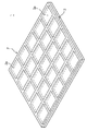
図1は、母基板の一例を示す図である。 FIG. 1 is a diagram illustrating an example of a mother board.
図1に示すように、母基板1は、薄膜トランジスタ−液晶ディスプレイ(TFT−LCD:ThinFilmTransistor−LiquidCrystalDisplay)用パネルである。母基板1は、略方形の板形状を有する第1母基板2と第2母基板3とからなる。第1母基板2と第2母基板3とは、上下に積層される。第1及び第2母基板2、3には、複数個の単位基板2a、3aが形成され、単位基板2a、3aは第1及び第2母基板2、3の平面上に格子状に配列される。第1母基板2は、薄膜トランジスタ基板が形成された基板であり、第2母基板3は、カラーフィルタ基板が形成された基板である。一方、母基板1は、フラットパネルディスプレイ用パネルの一種である有機発光ダイオード(OLED:OrganicLightEmittingDiodes)ディスプレイ用パネルなどである。
As shown in FIG. 1, a
図2は、本発明による基板切断装置10の構成を概略的に示す図面である。
FIG. 2 is a drawing schematically showing a configuration of the
図2に示すように、基板切断装置10は、母基板(図1の参照番号1)を複数個の単位基板に切断するためのものであって、ロード部11、第1スクライブ部12、第2スクライブ部13、ブレイク部14、及びアンロード部15を含む。ロード部11、第1スクライブ部12、第2スクライブ部13、ブレイク部14、及びアンロード部15は一列に順次に配置されることができる。しかし、本発明による基板切断装置10の配列構造はこれに限定されず、その他にもコ字状の配列構造などの多様な配列構造を有する。
As shown in FIG. 2, the
母基板1は、ロード部11を介して、基板切断装置10に搬入され、第1スクライブ部12は、第1母基板2上にスクライブラインを形成し、第2スクライブ部13は、第2母基板3上にスクライブラインを形成する。ブレイク部14は、ブレイクバー(BreakBar、図示せず)を用いて、母基板1に形成されたスクライブライン部位に力を加えて母基板1から単位基板を分離し、分離された基板はアンロード部15を介して基板切断装置10の外部に搬出される。
The
図3は、図2の第1及び第2スクライブ部の構成を概略的に示す図である。 FIG. 3 is a diagram schematically showing the configuration of the first and second scribe units of FIG.
図3に示すように、第1スクライブ部12は、母基板1を支持する支持部材(第1支持部材)100、スクライブラインを形成するスクライブユニット(第1スクライブユニット)200、及びスクライブユニット200を移動させる移動ユニット300を含む。母基板1は、下層の第2母基板3が支持部材100に載置された状態で支持され、スクライブユニット200は、支持部材100に載置された母基板1の上層、即ち、第1母基板2上にスクライブラインを形成する。移動ユニット300は、スクライブ工程の進行中に、第1母基板2上の切断予定線に沿ってスクライブユニット200を直線移動させる。
As shown in FIG. 3, the
第2スクライブ部13は、基板移送部材(第2支持部材)100’、スクライブユニット(第2スクライブユニット)200’、及び移動ユニット300を含む。基板移送部材100’は、第2母基板3が下方向を向いている状態で母基板1を第1スクライブ部12から第2スクライブ部13に移送し、第2スクライブ部13でスクライブ工程が進行される間、母基板1を支持する。基板移送部材100’は、母基板1の上層、即ち第1母基板2を吸着して母基板1を支持する。スクライブユニット200’と移動ユニット300とは、基板移送部材100’の下に配置される。スクライブユニット200’は、基板移送部材100’によって支持された母基板1の下層、即ち第2母基板3上にスクライブラインを形成する。移動ユニット300は、スクライブ工程の進行中に、第2母基板3上の切断予定線に沿ってスクライブユニット200’を直線移動させる。
The
このような構成によって、本発明による基板切断装置10は、母基板1の上層、即ち第1母基板2上にスクライブラインを形成し、母基板1を反転させることなく母基板1の上面と下面の方向性を維持した状態で、順次に母基板1の下層、即ち第2母基板3上にスクライブラインを形成できる。
With such a configuration, the
従来の基板切断装置は、母基板の一面にスクライブラインを形成した後、基板を反転させ、母基板の他面にスクライブラインを形成する。このため、基板の反転と関連して、装置のレイアウトが複雑になり、設備費用が増え、工程時間が長くなるなどの問題点があった。しかし、本発明は母基板を反転させることなく母基板の両面に対して順次にスクライブ工程を進行できるため、装置の構成を簡単化し、工程時間を短縮できるなどの利点を有する。 In the conventional substrate cutting apparatus, after a scribe line is formed on one surface of the mother substrate, the substrate is turned over to form a scribe line on the other surface of the mother substrate. For this reason, there has been a problem that the layout of the apparatus becomes complicated, the equipment cost increases, and the process time becomes longer in connection with the inversion of the substrate. However, the present invention has advantages such that the configuration of the apparatus can be simplified and the process time can be shortened because the scribing process can be sequentially performed on both sides of the mother board without inverting the mother board.
以下、第1及び第2スクライブ部12、13の構成をさらに詳しく説明する。先ず、第1スクライブ部12を説明し、その後、第2スクライブ部13を説明する。
Hereinafter, the configuration of the first and
図4は、図3の第1スクライブ部の斜視図であり、図5は、図4の第1スクライブ部の平面図であり、図6は、図4の支持部材の側面図である。そして、図7は、図4の「A」部分の拡大図であり、図8A及び図8Bは、図7のブラケットとリードスクリューとの間の結合関係を示す断面図である。 4 is a perspective view of the first scribe portion of FIG. 3, FIG. 5 is a plan view of the first scribe portion of FIG. 4, and FIG. 6 is a side view of the support member of FIG. 7 is an enlarged view of a portion “A” in FIG. 4, and FIGS. 8A and 8B are cross-sectional views showing a coupling relationship between the bracket and the lead screw in FIG. 7.
以下、第1方向Iは、後述する支持部材100の直線移動方向であり、第2方向IIは、第1スクライブ部12の平面配置構造上、第1方向Iに垂直する方向であり、第3方向IIIは、第1方向I及び第2方向IIに垂直する方向である。第1方向I及び第2方向IIは母基板1に格子状に配列された単位基板2a、3aの配列方向のうち何れか一方向にそれぞれ対応される。
Hereinafter, the first direction I is a linear movement direction of the
図4乃至図8Bに示すように、第1スクライブ部12は、支持部材100、スクライブユニット200(200a−1、200a−2、200b)、及び移動ユニット300(300a、300b)を含む。支持部材100は、母基板1を支持し、母基板1を第1方向Iに沿って直線移動させる。スクライブユニット200は、支持部材100に載置された母基板1の第1母基板2に接触して、第1方向Iスクライブライン及び第2方向IIスクライブラインを形成する。移動ユニット300は、スクライブユニット200を第2方向IIに直線移動させる。
As shown in FIGS. 4 to 8B, the
移動ユニット300aは、スクライブユニット200a−1、200a−2を第2方向IIに移動させてスクライブユニット200a−1、200a−2間の間隔を調節する。スクライブユニット200a−1、200a−2間の間隔を調節することによって、第1方向Iスクライブラインの間隔が調節される。第1方向Iスクライブラインの形成時にスクライブユニット200a−1、200a−2は固定され、母基板1は第1方向Iに移動される。
The moving
移動ユニット300bは、スクライブユニット200bを第2方向IIに直線移動させる。第2方向IIスクライブラインの形成時に、母基板1は固定され、スクライブユニット200bは移動ユニット300bによって第2方向IIに直線移動される。第2方向IIスクライブラインの間隔は母基板1の第1方向I移動によって調節される。
The moving
支持部材100は、テーブル120と駆動ユニット140とを含む。テーブル120には、母基板1が載置される。駆動ユニット140は、テーブル120を第1方向Iに直線移動させる。
The
テーブル120は、上部板122及び下部板124を有する。上部板122及び下部板124は、略長方形状を有し、上部板122が下部板124の上側に位置する。上部板122には、母基板1が載置される。上部板122は、母基板1と同じであるか、それより大きな面積を有する。上部板122の上面には、真空ライン(図示せず)と連結される複数のホール(図示せず)が形成され、母基板1は真空圧によって上部板122に固定される。また、上部板122又は下部板124には、付加的に母基板1を上部板122に固定させるクランプ(図示せず)が設置される。
The table 120 has an
駆動ユニット140は、テーブル120を第1方向Iに直線移動させる。駆動ユニット140は、ガイド142、ブラケット144、及び駆動機(図示せず)を有する。ガイド142は、第1方向Iに沿って長い形状を有して提供され、ベースB上の中央に装着される。ガイド142は、長さ方向に沿って同じ幅を有する。ガイド142の上面は、平らな形に提供され、ガイド142の両側面のそれぞれには、長さ方向に沿って長い形状を有して形成される溝141が提供される。
The
テーブル120は、ブラケット144によってガイド142に結合される。ブラケット144は、底板145、支持板147、及び結合板149を有する。底板145は、平らな長方形状を有し、ガイド142上に位置する。支持板147は、底板145の上面に垂直に固設され、テーブル120を支持するようにテーブル120の下部板124に固定結合される。支持板147は、二つが提供され、底板145の上面の両側に並列に配置される。結合板149は、底板145の底面に垂直に結合される側板149aと、側板149aの下端から内側に垂直に延びる挿入板149bと、を有する。挿入板149bはガイド142の側面に形成された溝141に挿入される。結合板149は、互いに対向するように二つが提供される。
The table 120 is coupled to the
駆動機は、テーブル120がガイド142によって案内され、第1方向Iに直線移動するように駆動力を提供する。駆動機としてモータとスクリューとを含むアセンブリが使われる。選択的にモータ、ベルト、及びプーリの組み合わせから構成されるアセンブリ、又はリニアモータ(LinearMotor)を含むアセンブリが駆動機として使われる。上述した多様なアセンブリの具体的な構成は、関連技術分野の当業者にとって周知であるので、これについての詳細な説明は省略する。
The driving machine provides driving force so that the table 120 is guided by the
スクライブユニット200は、第1方向スクライブユニット200a−1、200a−2と、第2方向スクライブユニット200bと、を含む。第1方向スクライブユニット200a−1、200a−2は、支持部材100が移動する経路上に第2方向IIに並列に提供され、第2方向スクライブユニット200bは、第1方向Iに沿って第1方向スクライブユニット200a−1、200a−2の一側に提供される。第1方向スクライブユニット200a−1、200a−2は、母基板1上に第1方向Iのスクライブラインを形成し、第2方向スクライブユニット200bは、母基板1上に第2方向IIのスクライブラインを形成する。
The
本実施の形態では、第1方向スクライブユニット200a−1、200a−2として二つのスクライブユニット200a−1、200a−2が提供される場合を例に挙げて説明するが、二つ以上の複数個のスクライブユニットが配置され得ることは無論である。第1方向スクライブユニット200a−1、200a−2は、後述する第1移動ユニット300aによって第2方向IIへ移動され間隔が調節される。
In the present embodiment, a case where two
図7に示すように、第1方向スクライブユニット200a−1は、第2方向IIに並列に配置された二つのスクライバー220a−1、240a−1を有し、第1方向スクライブユニット200a−2は、第2方向IIに並列に配置された二つのスクライバー220a−2、240a−2を有し、そして第2方向スクライブユニット200bは、第2方向IIに並列に配置された二つのスクライバー220b、240bを有する。スクライバー220a−1、240a−1、220a−2、240a−2、220b、240bは、同じ構成を有するため、以下、これらのうち一つのスクライバー220a−1を例に挙げて説明し、スクライバー240a−1、220a−2、240a−2、220b、240bについての説明は省略する。
As shown in FIG. 7, the first
図9は、図7のスクライバーの斜視図であり、図10は、図9のスクライバーの下端部の部分断面図であり、図11は、図10のスクライブホイールの平面図である。 9 is a perspective view of the scriber of FIG. 7, FIG. 10 is a partial sectional view of a lower end portion of the scriber of FIG. 9, and FIG. 11 is a plan view of the scribe wheel of FIG.
図9乃至図11に示すように、スクライバー220a−1は、スクライブホイール222、支持体224、押さえ部材226、そして振動子228を有する。スクライブホイール222は、スクライブ工程時、母基板1に接触され回転しつつ、母基板1にスクライブラインを形成する。スクライブホイール222には、ダイアモンド材質のホイール(wheel)が用いられる。スクライブホイール222の中央には円形の通孔222aが形成され、スクライブホイール222のエッジ222bは、鋭い形を有して提供される。
As illustrated in FIGS. 9 to 11, the
スクライブホイール222は、支持体224に支持される。支持体224は、本体224aと軸ピン224bとを有する。本体224aの下面には、一方向に本体224aを貫通する溝225が形成される。軸ピン224bは、断面が円形である長いロッド状を有する。軸ピン224bは、溝225の長さ方向と垂直する方向に溝225内に位置する。軸ピン224bの両端は、本体224aに固設される。軸ピン224bは、スクライブホイール222に形成された通孔222aを貫通する。スクライブホイール222が軸ピン224bによって支持される時、スクライブホイール222の一部は、溝225内に位置し、他の一部は支持体224の下に突出される。
The
押さえ部材226は、スクライブホイール222と母基板1とが接触する際、スクライブホイール222が所定の力で母基板1を押さえることができるように、スクライブホイール222を加圧する。一例として、押さえ部材226は、支持体224の上部に位置して空圧を用いて支持体224を下方向に押さえることによってスクライブホイール222を加圧する。
The pressing
振動子228は、スクライブ工程を進行する際、スクライブホイール222に振動を印加する。振動子228は、本体224a内部に装着され、振動子228としては超音波振動子が用いられる。
The
また、図4乃至図8Bを参照すると、移動ユニット300は第1移動ユニット300aと第2移動ユニット300bとを含む。第1移動ユニット300aは第1方向スクライブユニット200a−1、200a−2を第2方向IIへ移動させ、母基板1上の第1方向Iの切断予定線に第1方向スクライブユニット200a−1、200a−2を整列させる。第2移動ユニット300bは母基板1上の第2方向IIの切断予定線に沿って第2方向スクライブユニット200bを移動させる。そして、第1方向スクライブユニット200a−1、200a−2の直線移動と、第2方向スクライブユニット200bの直線移動とは、ガイド部材370によって案内される。
4 to 8B, the moving
第1移動ユニット300aは、第1垂直支持台310a、第1ブラケット330a−1、330a−2、及び第1駆動部材350を含む。第1垂直支持台310aは、第2方向IIに一定の距離離隔するように配置される。第1垂直支持台310aは、母基板1が第1方向Iに沿って直線移動する際、母基板1が第1垂直支持台310a間を通ることができるように配置される。第1垂直支持台310aの上端にはガイド部材370が固設され、ガイド部材370の長さ方向は第2方向IIに整列される。ガイド部材370の上面及び下面には、長さ方向に沿って長い形状を有して溝372、374が提供される。
The first moving
第1方向スクライブユニット200a−1は、第1ブラケット330a−1によってガイド部材370に結合され、第1方向スクライブユニット200a−2は、第1ブラケット330a−2によってガイド部材370に結合される。第1ブラケット330a−1、330a−2は、同じ構造を有するので、以下、第1ブラケット330a−1についてのみ説明する。第1ブラケット330a−1は、図7に示すように、支持板332と結合板334とを有する。支持板332は、平らな長方形の板状を有し、ガイド部材370の一側面上に位置する。結合板334は支持板332の上側及び下側から支持板332に垂直に突出した側板334aと、ガイド部材370に形成された溝372に挿入される挿入板334bを有する。
The first
第1駆動部材350は、第1ブラケット330a−1、330a−2がガイド部材370に沿って直線移動するように駆動力を提供する。第1駆動部材350はガイド部材370に平行をなすように配置される第1リードスクリュー352、354を有する。図8Aに示すように、第1リードスクリュー352上には、第1ブラケット330a−1が直線移動可能に装着され、第1リードスクリュー354上には、第1ブラケット330a−2が直線移動可能に装着される。即ち、第1ブラケット330a−1には、第1リードスクリュー352、354が挿入されるが、第1リードスクリュー352は、ブラケット330a−1に形成された雌ネジ部335−1と噛み合うことに対し、第1リードスクリュー354は、第1ブラケット330a−1に形成されたホール336−1と接触されない状態で貫通される。これと同様に、第1ブラケット330a−2には、第1リードスクリュー352、354が挿入されるが、第1リードスクリュー352は、第1ブラケット330a−2に形成されたホール336−2と接触されない状態で貫通することに対し、第1リードスクリュー354は、ブラケット330a−2に形成された雌ネジ部335−2と噛み合う。
The
第1リードスクリュー352の駆動時に第1ブラケット330−1は、直線移動するが、第1ブラケット330−2は、移動しなく、第1リードスクリュー354の駆動時に第1ブラケット330−1は、移動しないが、第1ブラケット330−2は直線移動する。このような駆動方式によって、第1ブラケット330−1に連結した第1方向スクライブユニット200a−1と第1ブラケット330−2に連結した第1方向スクライブユニット200a−2とが第2方向IIに沿って移動され、第1方向スクライブユニット200a−1、200a−2間の間隔が調節される。
The first bracket 330-1 moves linearly when the
第1リードスクリュー352の一端には、回転力を提供する第1駆動機353が連結され、第1リードスクリュー354の一端には、回転力を提供する第1駆動機355が連結される。第1及び第2駆動機353、355としては、モータなどの駆動機が用いられる。第1駆動部材350としてモータとリードスクリューとを含むアセンブリを例に挙げて説明したが、この他にもシリンダなどのように第1ブラケット330a−1、330a−2に直線駆動力を提供できる多様な駆動機が用いられる。
One end of the
図7に示すように、第1方向スクライブユニット200a−1は、上下に移動できるように第1ブラケット330a−1の支持板332に装着される。一例として、支持板332には、第3方向IIIにスリット形状の案内溝331が形成され、第1方向スクライブユニット200a−1のスクライバー220a−1、240a−1が案内溝331に挿入された支持軸(図示せず)にそれぞれ結合される。第1方向スクライブユニット200a−2も上下に移動できるように第1ブラケット330a−2に連結され、連結構造は、第1方向スクライブユニット200a−1の連結構造と同じであるため、これについての説明は省略する。
As shown in FIG. 7, the first
第2移動ユニット300bは、第2垂直支持台310b、第2ブラケット330b、及び第2駆動部材350’を含む。第2垂直支持台310bは、第2方向IIに一定の距離が離隔するように配置される。第2垂直支持台310bは、母基板1が第1方向Iに沿って直線移動する際、母基板1が第2垂直支持台310b間を通ることができるように配置される。そして、第2垂直支持台310bは、その上端が第1垂直支持台310aの上端に固定されたガイド部材370に固定結合されるように配置される。
The second moving
第2方向スクライブユニット200bは、第2ブラケット330bによってガイド部材370に結合される。第2ブラケット330bは、上述の第1ブラケット330a−1と同じ構造を有するので、これについての説明を省略する。
The second
第2駆動部材350’は、第2ブラケット330bがガイド部材370に沿って直線移動するように駆動力を提供する。第2駆動部材350’は、ガイド部材370に平行するように配置される第2リードスクリュー352’を有する。図8Bに示すように、第2リードスクリュー352’上には第2ブラケット330bが直線移動可能に装着される。即ち、第2ブラケット330bに形成された雌ネジ部335’と第2リードスクリュー352’とが噛み合う。このような駆動方式によって、第2ブラケット330bに連結された第2方向スクライブユニット200bが第2方向IIに沿って移動される。
The
第2リードスクリュー352’の一端には、回転力を提供する第2駆動機353’が連結される。第2駆動機353’としては、モータなどの駆動機が用いられる。第2駆動部材350’として、モータとリードスクリューとを含むアセンブリを例に挙げて説明したが、この他にもシリンダなどのように第2ブラケット330bに直線駆動力を提供できる多様な駆動機が用いられる。
One end of the second lead screw 352 'is connected to a second driver 353' that provides a rotational force. As the second driving machine 353 ', a driving machine such as a motor is used. The
第2方向スクライブユニット200bは、上下に移動できるように第2ブラケット330bに連結され、連結構造は、上述の第1方向スクライブユニット200a−1の連結構造と同じであるため、これについての説明は省略する。
The second
上述した第1及び第2移動ユニット300a、300bの動作は、制御部400によって制御される。制御部400は、第1移動ユニット300aの第1駆動機353、355と、第2移動ユニット300bの第2駆動機353’の動作を制御する。第1駆動機353、355の制御によって、第1方向スクライブユニット200a−1、200a−2が第2方向IIへ移動され、第1方向スクライブユニット200a−1、200a−2間の間隔が調節される。そして、第2駆動機353’の制御によって、第2方向スクライブユニット200bが第2方向IIへ移動できる。
The operations of the first and second moving
上述したような構成を有する本発明による第1スクライブ部12を用いて母基板1の第1母基板2上にスクライブラインを形成する過程を説明すると、以下のとおりである。
A process of forming a scribe line on the
図12A乃至図12Kは、本発明による第1スクライブ部を利用して母基板上にスクライブラインを形成する過程を示す図である。 12A to 12K are views illustrating a process of forming a scribe line on a mother substrate using the first scribe unit according to the present invention.
第1母基板2が上側を向くように、母基板1がテーブル120の上部板122上に載置される。テーブル120は、駆動機(図示せず)によって第1方向Iに直線移動される(図12A)。テーブル120が既定の位置(即ち、第1母基板2の第1切断予定線aが第2方向スクライブユニット200bに整列された位置)まで移動すると、テーブル120の移動が止まる(図12B)。
The
以後、第2方向スクライブユニット200bが第2方向IIに沿って第1母基板2の第1切断予定線aに整列された状態で、第2移動ユニット300bの第2駆動機353’を駆動させ、第1母基板2の一側方向に第2方向スクライブユニット200bを移動させる。この際、第2方向スクライブユニット200bのスクライバー220b、240bのうち一つのスクライバー220b、240bが、第1母基板2と接触できる高さに位置するように下方向に移動される(図12C)。
Thereafter, the
このような状態で、第2移動ユニット300bの第2駆動機353’を駆動させて第2方向スクライブユニット200bを第2方向IIに沿って第1母基板2を横切って移動させる。この際、第2方向スクライブユニット200bのスクライバー220b、240bのうち、第1母基板2に接触するスクライバーが第1母基板2上にクラックを形成する。切断予定線aに沿ってクラックが連続的に形成されることによって、第1母基板2上にはスクライブラインが形成される。スクライブラインの形成後に第2方向スクライブユニット200bのスクライバー220b、240bは、上の方向へ移動される(図12D)。
In this state, the second driving unit 353 'of the second moving
テーブル120は、駆動機(図示せず)によって第1方向Iへ直線移動される。テーブル120が既設定された位置(即ち、第1母基板2の第2切断予定線bが第2方向スクライブユニット200bに整列された位置)まで移動すると、テーブル120の移動が止まる。そして、第2方向スクライブユニット200bのスクライバー220b、240bのうち一つのスクライバー220b、240bが第1母基板2と接触できる高さに位置するように下方向に移動される(図12E)。
The table 120 is linearly moved in the first direction I by a driving machine (not shown). When the table 120 moves to a preset position (that is, a position where the second scheduled cutting line b of the
以後、第2移動ユニット300bの第2駆動機353’を駆動させ、第2方向スクライブユニット200bを第2方向IIに沿って第1母基板2を横切って移動させる。この際、第2方向スクライブユニット200bのスクライバー220b、240bのうち、第1母基板2に接触するスクライバーが第1母基板2上にクラックを形成する。切断予定線bに沿ってクラックが連続的に形成されることによって、第1母基板2上には、スクライブラインが形成される。スクライブラインの形成後に第2方向スクライブユニット200bのスクライバー220b、240bは、上の方向へ移動される(図12F)。
Thereafter, the second driving unit 353 'of the second moving
上記で説明したような過程の繰り返しによって、残りの切断予定線c、dに沿って第1母基板2上にスクライブラインを形成し、以後、テーブル120は、駆動機(図示せず)によって第1方向Iへ直線移動される。テーブル120が既設定された位置まで移動すると、テーブル120の移動が止まる(図12G)。
By repeating the process as described above, scribe lines are formed on the
以後、第1移動ユニット300aの駆動機353、355を駆動させ、第1方向スクライブユニット200a−1、200a−2間の間隔を調節する。第1移動ユニット300aによって第1方向スクライブユニット200a−1は既設定された位置(即ち、第1方向スクライブユニット200a−1が第1母基板2の切断予定線eに整列された位置)まで移動され、第1方向スクライブユニット200a−2は、既設定された位置(即ち、第1方向スクライブユニット200a−2が第1母基板2の切断予定線fに整列された位置)まで移動される。この際、第1方向スクライブユニット200a−1のスクライバー220a−1、240a−1のうち、一つのスクライバー220a−1、240a−1が第1母基板2と接触できる高さに位置するように下方向へ移動され、第1方向スクライブユニット200a−2のスクライバー220a−2、240a−2のうち、一つのスクライバー220a−2、240a−2が第1母基板2と接触できる高さに位置するように下方向へ移動される(図12H)。
Thereafter, the driving
第1方向スクライブユニット200a−1、200a−2が第1方向Iに沿って第1母基板2の切断予定線e、fに整列された状態で、テーブル120は駆動機(図示せず)によって第1方向Iへ直線移動される。テーブル120が既設定された位置(即ち、第1母基板2の切断予定線e、fに沿って、第1母基板2上にスクライブラインが形成された位置)まで移動すると、テーブル120の移動が止まる(図12I)。
With the first
以後、第1移動ユニット300aの駆動機353、355を駆動させ、第1方向スクライブユニット200a−1、200a−2が切断予定線g、hに整列されるように第1方向スクライブユニット200a−1、200a−2を移動させる。第1移動ユニット300aによって第1方向スクライブユニット200a−1は、既設定された位置(即ち、第1方向スクライブユニット200a−1が第1母基板2の切断予定線gに整列された位置)まで移動され、第1方向スクライブユニット200a−2は既設定された位置(即ち、第1方向スクライブユニット200a−2が第1母基板2の切断予定線hに整列された位置)まで移動される。この際、第1方向スクライブユニット200a−1のスクライバー220a−1、240a−1のうち、一つのスクライバー220a−1、240a−1が第1母基板2と接触できる高さに位置するように下方向へ移動され、第1方向スクライブユニット200a−2のスクライバー220a−2、240a−2のうち、一つのスクライバー220a−2、240a−2が第1母基板2と接触できる高さに位置するように下方向へ移動される(図12J)。
Thereafter, the driving
第1方向スクライブユニット200a−1、200a−2が第1方向Iに沿って第1母基板2の切断予定線g、hに整列された状態で、テーブル120は駆動機(図示せず)によって第1方向Iへ直線移動する。テーブル120が既設定された位置(即ち、第1母基板2の切断予定線g、hに沿って第1母基板2上にスクライブラインが形成された位置)まで移動すると、テーブル120の移動が止まる(図12K)。
With the first
次に、第2スクライブ部13の構成及び動作を説明する。
Next, the configuration and operation of the
図13は、図3の第2スクライブ部13の斜視図であり、図14は図13の「C」部分の拡大図である。ここで、図4及び図7に示す構成要素と同じ構成を有する要素については、同じ参照番号で記載する。
13 is a perspective view of the
第2スクライブ部13は、基板移送部材100’、スクライブユニット200’、及び移動ユニット300を含む。
The
基板移送部材100’は、第2母基板3が下方向を向いている状態で、母基板1を第1スクライブ部12から第2スクライブ部13に移送し、第2スクライブ部13でスクライブ工程を進行する間に母基板1を支持する。
The
基板移送部材100’は、第1母基板2にスクライブラインが形成され、第2母基板3が下方向を向いている状態の母基板1を、第1スクライブ部12から第2スクライブ部13に移送する。そして基板移送部材100’は、第2スクライブ部13で母基板1の第2母基板3に対してスクライブ工程を進行する間に第1母基板2を吸着支持する。
The
基板移送部材100’は、移送体110’及び吸着板120’を含む。移送体110’は、板状の支持板112’と、支持板112’の下面から下方向に延長した複数の支持台114’と、を有する。支持台114’の端部には、吸着板120’が結合される。吸着板120’は、母基板1を吸着して支持するためのものであって、母基板1が接触する吸着板120’の下面には、複数個の吸着孔(図示せず)が形成され、吸着板120’の内部には、吸着孔(図示せず)に連通される真空ライン(図示せず)が形成される。そして、基板移送部材100’は、駆動装置(図示せず)によって第1方向I又は第3方向IIIに直線移動できる。
The
基板移送部材100’の吸着板120’には、母基板1が吸着支持され、この際、母基板1は、第2母基板3が下方向を向くように第1母基板2が吸着板120’に面接触された状態で支持される。
The
基板移送部材100’の下には、スクライブユニット200’と移動ユニット300とが提供される。スクライブユニット200’は、基板移送部材100’によって支持された母基板1の下層、即ち第2母基板3上にスクライブラインを形成し、移動ユニット300は、スクライブ工程の進行中に第2母基板3上の切断予定線に沿ってスクライブユニット200’を直線移動させる。
A
スクライブユニット200’及び移動ユニット300は、第1スクライブ部12のスクライブユニット200及び移動ユニット300と同じ構成を有するので、これについての詳細な説明は省略する。但し、第2スクライブ部13のスクライブユニット200':200'a−1、200'a−2、200'bは、第1スクライブ部12のスクライブユニット200:200a−1、200a−2、200bの倒立像をなすように設置される。即ち、スクライブユニット200':200'a−1、200'a−2、200'bは、スクライブホイール222’がスクライブユニット200':200'a−1、200'a−2、200'bの上部に位置する母基板1を向くように設置される。
Since the
上述のような構成を有する第2スクライブ部13におけるスクライブ工程は、第1スクライブ部12におけるスクライブ工程と同じ順序で進行され、これについての詳細な説明は関連技術分野の当業者によって容易に推論できるので、ここでは、これについての説明を省略する。
The scribing process in the
一方、以上では、第1スクライブ部12が母基板1の上面、即ち、第1母基板2にスクライブラインを形成し、第2スクライブ部13が母基板1の下面、即ち第2母基板3にスクライブラインを形成するように構成された基板切断装置を例に挙げて説明したが、本発明の基板切断装置はこれに限定されず、これに対して、第1スクライブ部12が母基板1の下面、即ち第2母基板3にスクライブラインを形成し、第2スクライブ部13が母基板1の上面、即ち第1母基板2にスクライブラインを形成するように構成することもできる。
On the other hand, in the above, the
以上で説明した構成を有する本発明による基板切断装置は、母基板の上面と下面の方向性を維持した状態で、母基板の上下両面のうち何れか一面にスクライブラインを形成し、順次に他の一面にスクライブラインを形成できる。 The substrate cutting apparatus according to the present invention having the configuration described above forms a scribe line on one of the upper and lower surfaces of the mother substrate while maintaining the orientation of the upper surface and the lower surface of the mother substrate. A scribe line can be formed on one side.
そして、本発明による基板切断装置は、基板を反転させることなく、スクライブ工程を進行できるため、工程時間を短縮して全体工程の生産性を向上させることができる。 And since the board | substrate cutting device by this invention can advance a scribe process, without reversing a board | substrate, it can shorten process time and can improve the productivity of the whole process.
また、本発明による基板切断装置は、基板の反転と関連した設備が省略されることによって、設備のレイアウトを簡素化して設備費用を節減できる。 Further, the substrate cutting apparatus according to the present invention can simplify the layout of the facility and reduce the facility cost by omitting the facility related to the inversion of the substrate.
以上の説明は、本発明の技術思想を例示的に説明したものに過ぎず、本発明が属する技術分野における通常の知識を有する者であれば、本発明の本質的な特性から外れない範囲で多様な修正及び変形が可能である。したがって、本発明に開示された実施の形態は、本発明の技術思想を限定するためのものではなく、説明するためのものであり、このような実施の形態によって本発明の技術思想の範囲が限定されるものではない。本発明の保護範囲は、特許請求の範囲によって解析されるべきであり、それと同等な範囲内にあるすべての技術思想は、本発明の権利範囲に含まれるものと解析されるべきである。 The above description is merely illustrative of the technical idea of the present invention, and a person having ordinary knowledge in the technical field to which the present invention belongs can be used without departing from the essential characteristics of the present invention. Various modifications and variations are possible. Therefore, the embodiments disclosed in the present invention are not intended to limit the technical idea of the present invention, but are for explanation. The scope of the technical idea of the present invention is limited by such an embodiment. It is not limited. The protection scope of the present invention should be analyzed by the claims, and all technical ideas within the equivalent scope should be analyzed as being included in the scope of the right of the present invention.
1 母基板
12 第1スクライブ部
13 第2スクライブ部
100 支持部材
200 スクライブユニット
300 移動ユニット
400 制御部
100' 基板移送部材
200' スクライブユニット
1 Mother board
12
Claims (18)
前記母基板の上面と下面のうち、何れか一面にスクライブラインを形成する第1スクライブ部と、
上面と下面の方向性が維持された状態で、前記第1スクライブ部から移送される前記母基板の他の一面にスクライブラインを形成する第2スクライブ部と、を含むことを特徴とするスクライブ装置。 An apparatus for performing a scribe process for separating a mother substrate on which a plurality of unit substrates are formed into unit substrates,
A first scribe part for forming a scribe line on one of the upper surface and the lower surface of the mother substrate;
A scribing apparatus comprising: a second scribing unit that forms a scribing line on the other surface of the mother substrate transferred from the first scribing unit in a state in which the orientation of the upper surface and the lower surface is maintained. .
前記第2スクライブ部は、前記母基板の上面を支持する第2支持部材と、前記母基板の下面にスクライブラインを形成する第2スクライブユニットと、を含むことを特徴とする請求項1に記載のスクライブ装置。 The first scribe portion includes a first support member that supports a lower surface of the mother substrate, and a first scribe unit that forms a scribe line on the upper surface of the mother substrate,
The second scribe part includes a second support member that supports an upper surface of the mother substrate and a second scribe unit that forms a scribe line on the lower surface of the mother substrate. Scribing device.
前記第2スクライブ部は、前記母基板の下面を支持する第2支持部材と、前記母基板の上面にスクライブラインを形成する第2スクライブユニットと、を含むことを特徴とする請求項1に記載のスクライブ装置。 The first scribe unit includes a first support member that supports an upper surface of the mother substrate, and a first scribe unit that forms a scribe line on the lower surface of the mother substrate.
The second scribe part includes a second support member that supports a lower surface of the mother substrate and a second scribe unit that forms a scribe line on the upper surface of the mother substrate. Scribing device.
前記ロード部から伝達された前記母基板の上面と下面のうち、何れか一面に、スクライブラインを形成する第1スクライブ部と、
上面と下面の方向性が維持された状態で、前記第1スクライブ部から移送された前記母基板の他の一面にスクライブラインを形成する第2スクライブ部と、
前記母基板に生成されたスクライブラインに沿って、前記母基板を単位基板に分離するブレイク部と、
分離された前記単位基板をアンロードするアンロード部と、を含むことを特徴とする基板切断装置。 A load unit on which a mother board on which a plurality of unit boards are formed is loaded;
A first scribe part for forming a scribe line on one of the upper surface and the lower surface of the mother board transmitted from the load part;
A second scribe part for forming a scribe line on the other surface of the mother substrate transferred from the first scribe part in a state in which the orientation of the upper surface and the lower surface is maintained;
A break part for separating the mother substrate into unit substrates along a scribe line generated on the mother substrate;
An unloading unit for unloading the separated unit substrate.
前記第2スクライブ部は、前記母基板の上面を支持する第2支持部材と、前記母基板の下面にスクライブラインを形成する第2スクライブユニットと、を含むことを特徴とする請求項6に記載の基板切断装置。 The first scribe portion includes a first support member that supports a lower surface of the mother substrate, and a first scribe unit that forms a scribe line on the upper surface of the mother substrate,
The second scribe portion includes a second support member that supports an upper surface of the mother substrate and a second scribe unit that forms a scribe line on the lower surface of the mother substrate. Board cutting equipment.
前記第2スクライブ部は、前記母基板の下面を支持する第2支持部材と、前記母基板の上面にスクライブラインを形成する第2スクライブユニットと、を含むことを特徴とする請求項6に記載の基板切断装置。 The first scribe unit includes a first support member that supports an upper surface of the mother substrate, and a first scribe unit that forms a scribe line on the lower surface of the mother substrate.
The second scribe portion includes a second support member that supports a lower surface of the mother substrate and a second scribe unit that forms a scribe line on the upper surface of the mother substrate. Board cutting equipment.
前記母基板の上面と下面のうち、何れか一面にスクライブラインを形成し、
前記母基板の上面と下面の方向性を維持した状態で、前記母基板の他の一面にスクライブラインを形成することを特徴とする基板切断方法。 A method of separating a mother substrate on which a unit substrate is formed into unit substrates,
A scribe line is formed on one of the upper surface and the lower surface of the mother substrate,
A substrate cutting method, wherein a scribe line is formed on the other surface of the mother substrate while maintaining the orientation of the upper surface and the lower surface of the mother substrate.
スクライブラインが形成された前記母基板の上面を吸着支持した状態で、前記母基板の下面にスクライブラインを形成することを特徴とする請求項9に記載の基板切断方法。 In a state where the lower surface of the mother substrate is supported, a scribe line is formed on the upper surface of the mother substrate,
The substrate cutting method according to claim 9, wherein the scribe line is formed on the lower surface of the mother substrate in a state where the upper surface of the mother substrate on which the scribe line is formed is sucked and supported.
スクライブラインが形成された前記母基板の下面を支持した状態で、前記母基板の上面にスクライブラインを形成することを特徴とする請求項9に記載の基板切断方法。 With the upper surface of the mother substrate being sucked and supported, a scribe line is formed on the lower surface of the mother substrate,
The substrate cutting method according to claim 9, wherein the scribe line is formed on the upper surface of the mother substrate in a state where the lower surface of the mother substrate on which the scribe line is formed is supported.
前記母基板の上面と下面のうち、何れか一面にスクライブラインを形成する第1スクライブ部と、
前記第1スクライブ部に隣接して配置され、前記第1スクライブ部から移送される前記母基板の異なる一面にスクライブラインを形成する第2スクライブ部と、を含むことを特徴とするスクライブ装置。 In an apparatus for performing a scribe process for separating a mother substrate on which a plurality of unit substrates are formed into unit substrates,
A first scribe part for forming a scribe line on one of the upper surface and the lower surface of the mother substrate;
And a second scribe unit that is disposed adjacent to the first scribe unit and forms a scribe line on a different surface of the mother substrate transferred from the first scribe unit.
前記母基板の下面を支持し、第1方向に直線移動が可能である第1支持部材と、
前記第1支持部材の移動経路上部に提供され、前記母基板の上面にスクライブラインを形成する第1スクライブユニットと、を含むことを特徴とする請求項12に記載のスクライブ装置。 The first scribe unit is
A first support member that supports the lower surface of the mother substrate and is capable of linear movement in a first direction;
The scribing apparatus according to claim 12, further comprising: a first scribing unit provided on a moving path of the first support member and forming a scribing line on an upper surface of the mother substrate.
前記第1方向に沿って前記第1スクライブユニットの後方に提供される第2スクライブユニットと、
前記第1及び第2スクライブユニットの上部から前記第1方向に沿って直線移動が可能で、そして前記第1方向に垂直な方向に沿って上下移動して前記第1支持部材に置かれた前記母基板の上面を吸着する第2支持部材と、を含み、
前記第2スクライブユニットは、前記第2支持部材に吸着された前記母基板の下面にスクライブラインを形成することを特徴とする請求項13に記載のスクライブ装置。 The second scribe unit is
A second scribe unit provided behind the first scribe unit along the first direction;
The linear movement is possible along the first direction from the upper part of the first and second scribe units, and the vertical movement is performed along a direction perpendicular to the first direction, and the first scribe unit is placed on the first support member. A second support member that adsorbs the upper surface of the mother substrate,
The scriber according to claim 13, wherein the second scribe unit forms a scribe line on a lower surface of the mother substrate adsorbed by the second support member.
前記母基板を吸着するように表面に多数の吸着孔が形成された吸着板と、
前記吸着板を前記上下方向と前記第1方向に直線移動させる駆動装置と、を含むことを特徴とする請求項14に記載のスクライブ装置。 The second support member is
A suction plate having a plurality of suction holes formed on the surface so as to suck the mother substrate;
The scribing device according to claim 14, further comprising: a driving device that linearly moves the suction plate in the vertical direction and the first direction.
前記母基板の上面を吸着し、第1方向に直線移動可能である第1支持部材と、
前記第1支持部材の移動経路下部に提供され、前記母基板の下面にスクライブラインを形成する第1スクライブユニットと、を含むことを特徴とする請求項12に記載のスクライブ装置。 The first scribe unit is
A first support member that adsorbs an upper surface of the mother substrate and is linearly movable in a first direction;
The scribing apparatus according to claim 12, further comprising: a first scribing unit provided at a lower part of the moving path of the first support member and forming a scribe line on a lower surface of the mother board.
前記第1スクライブユニットの後方に位置し、前記第1支持部材から前記母基板が伝達されて前記母基板の下面を支持し、前記第1方向に直線移動可能である第2支持部材と、
前記第2支持部材の移動経路上部に提供され、前記母基板の上面にスクライブラインを形成する第2スクライブユニットと、を含むことを特徴とする請求項17に記載のスクライブ装置。 The second scribe unit is
A second support member located behind the first scribe unit, wherein the mother board is transmitted from the first support member to support the lower surface of the mother board, and is linearly movable in the first direction;
The scribing apparatus according to claim 17, further comprising: a second scribing unit provided at an upper part of a movement path of the second support member and forming a scribe line on an upper surface of the mother substrate.
Applications Claiming Priority (2)
| Application Number | Priority Date | Filing Date | Title |
|---|---|---|---|
| KR1020080041878A KR101010310B1 (en) | 2008-05-06 | 2008-05-06 | Scribing device and substrate cutting device and method using same |
| KR10-2008-0041878 | 2008-05-06 |
Publications (2)
| Publication Number | Publication Date |
|---|---|
| JP2009269814A JP2009269814A (en) | 2009-11-19 |
| JP4985996B2 true JP4985996B2 (en) | 2012-07-25 |
Family
ID=41270263
Family Applications (1)
| Application Number | Title | Priority Date | Filing Date |
|---|---|---|---|
| JP2009111199A Active JP4985996B2 (en) | 2008-05-06 | 2009-04-30 | Scribing apparatus, and substrate cutting apparatus and method using the same |
Country Status (4)
| Country | Link |
|---|---|
| JP (1) | JP4985996B2 (en) |
| KR (1) | KR101010310B1 (en) |
| CN (1) | CN101575166B (en) |
| TW (1) | TWI400203B (en) |
Families Citing this family (10)
| Publication number | Priority date | Publication date | Assignee | Title |
|---|---|---|---|---|
| JP5156085B2 (en) * | 2010-12-13 | 2013-03-06 | 三星ダイヤモンド工業株式会社 | Method for dividing bonded substrates |
| KR101110321B1 (en) * | 2011-08-11 | 2012-02-16 | (주)큐엠씨 | Substrate Splitter and Substrate Splitter |
| CN104227570A (en) * | 2013-06-17 | 2014-12-24 | 株式会社太星技研 | Unitary armorplate glass processing system for forming G2-mode touch sensors of cell units |
| KR101703032B1 (en) * | 2014-08-29 | 2017-02-07 | 주식회사 태성기연 | Glass panel overhead system |
| KR20160123454A (en) * | 2015-04-15 | 2016-10-26 | 주식회사 탑 엔지니어링 | Scribing apparatus |
| CN106827260B (en) * | 2017-03-16 | 2018-12-18 | 佛山市永盛达机械有限公司 | A kind of method and device of high pressure waterjet |
| JP7075652B2 (en) * | 2017-12-28 | 2022-05-26 | 三星ダイヤモンド工業株式会社 | Scribe device and scribe method |
| CN110372196A (en) * | 2018-04-12 | 2019-10-25 | 蚌埠市鑫诚玻璃机械有限公司 | Full-automatic doubling glass cutting machine process flow |
| CN113060932A (en) * | 2021-03-24 | 2021-07-02 | 深圳市巨艾伦控股有限公司 | Glass cutting machine with automatic spindle distance adjusting mechanism |
| JP2023074021A (en) * | 2021-11-17 | 2023-05-29 | Jswアクティナシステム株式会社 | Laser cutting device, laser cutting method, and display manufacturing method |
Family Cites Families (9)
| Publication number | Priority date | Publication date | Assignee | Title |
|---|---|---|---|---|
| JP2532537Y2 (en) * | 1991-12-06 | 1997-04-16 | 三星ダイヤモンド工業株式会社 | Cutter head for substrate scribing |
| JPH1164834A (en) * | 1997-08-11 | 1999-03-05 | Hitachi Ltd | Liquid crystal display substrate manufacturing equipment |
| JP4402883B2 (en) * | 2001-01-17 | 2010-01-20 | 三星ダイヤモンド工業株式会社 | Dividing device, dividing system and dividing method |
| JP3991608B2 (en) * | 2001-03-28 | 2007-10-17 | セイコーエプソン株式会社 | LASER CUTTING METHOD, ELECTRO-OPTICAL DEVICE MANUFACTURING METHOD, ELECTRO-OPTICAL DEVICE, ELECTRONIC DEVICE, AND LASER CUTTING DEVICE |
| KR100817129B1 (en) * | 2002-02-07 | 2008-03-27 | 엘지.필립스 엘시디 주식회사 | Cutting device and method of liquid crystal panel |
| TW200408061A (en) * | 2002-07-02 | 2004-05-16 | Mitsuboshi Diamond Ind Co Ltd | Substrate slicing system for sealed substrates and the substrate slicing method |
| KR100752551B1 (en) * | 2002-11-22 | 2007-08-29 | 미쓰보시 다이야몬도 고교 가부시키가이샤 | Substrate-cutting system, substrate-producing apparatus, substrate-scribing method, and substrate-cutting method |
| US7770500B2 (en) | 2004-03-15 | 2010-08-10 | Mitsuboshi Diamond Industrial Co., Ltd. | Substrate dividing system, substrate manufacturing equipment, substrate scribing method and substrate dividing method |
| KR100642902B1 (en) | 2004-12-28 | 2006-11-08 | 삼성코닝정밀유리 주식회사 | Glass substrate cutting device |
-
2008
- 2008-05-06 KR KR1020080041878A patent/KR101010310B1/en not_active IP Right Cessation
-
2009
- 2009-04-30 JP JP2009111199A patent/JP4985996B2/en active Active
- 2009-05-05 CN CN2009101375352A patent/CN101575166B/en active Active
- 2009-05-06 TW TW098114978A patent/TWI400203B/en active
Also Published As
| Publication number | Publication date |
|---|---|
| JP2009269814A (en) | 2009-11-19 |
| KR101010310B1 (en) | 2011-01-25 |
| TWI400203B (en) | 2013-07-01 |
| CN101575166A (en) | 2009-11-11 |
| TW200948730A (en) | 2009-12-01 |
| KR20090116139A (en) | 2009-11-11 |
| CN101575166B (en) | 2012-01-04 |
Similar Documents
| Publication | Publication Date | Title |
|---|---|---|
| JP4985996B2 (en) | Scribing apparatus, and substrate cutting apparatus and method using the same | |
| JP2009209033A (en) | Scribing device, and substrate cutting apparatus and method utilizing the same | |
| KR100889308B1 (en) | Scribing device and method and substrate cutting device using same | |
| TWI398417B (en) | Scribing unit and apparatus for scribing panel with the scribing unit, and scribing method and method for manufacturing substrate | |
| JP6280332B2 (en) | Substrate reverse transfer device | |
| CN102097371B (en) | Substrate dividing device | |
| KR20130135531A (en) | Substrate separation device and for method for separating the substrate using thereof | |
| CN101236322B (en) | Method and apparatus for producing electro-optical device | |
| JP2016120725A (en) | Break device for brittle material substrate | |
| JP5156085B2 (en) | Method for dividing bonded substrates | |
| KR101134655B1 (en) | Substrate cutting apparatus | |
| JP2009126780A (en) | Scribing device and method, and substrate cutoff device using the same | |
| KR101236805B1 (en) | Substrate cutting apparatus and method | |
| JP2019196281A (en) | Substrate dividing device | |
| US20080251557A1 (en) | Scribing unit and apparatus for scribing panel with the scribing unit, and scribing method and method for manufacutring substrate | |
| KR20160111603A (en) | Breaking system for attached substrate | |
| KR100905898B1 (en) | Scribing device and substrate cutting device and method using same | |
| TW202039383A (en) | Apparatus for controlling slope of stage and apparatus for dividing substrate using the same | |
| KR20090052836A (en) | Scribing device and substrate cutting device using same | |
| KR101021986B1 (en) | Scribing apparatus for forming scribe line and scribe line forming method | |
| KR101180780B1 (en) | Substrate dividing apparatus and method for dividing substrate using thereof | |
| KR100964329B1 (en) | Scribing method | |
| CN106045292A (en) | Scribing apparatus | |
| KR20090124448A (en) | Scribing device | |
| KR102068032B1 (en) | Scribe apparatus |
Legal Events
| Date | Code | Title | Description |
|---|---|---|---|
| TRDD | Decision of grant or rejection written | ||
| A01 | Written decision to grant a patent or to grant a registration (utility model) |
Free format text: JAPANESE INTERMEDIATE CODE: A01 Effective date: 20120321 |
|
| A01 | Written decision to grant a patent or to grant a registration (utility model) |
Free format text: JAPANESE INTERMEDIATE CODE: A01 |
|
| A61 | First payment of annual fees (during grant procedure) |
Free format text: JAPANESE INTERMEDIATE CODE: A61 Effective date: 20120417 |
|
| R150 | Certificate of patent or registration of utility model |
Free format text: JAPANESE INTERMEDIATE CODE: R150 Ref document number: 4985996 Country of ref document: JP Free format text: JAPANESE INTERMEDIATE CODE: R150 |
|
| FPAY | Renewal fee payment (event date is renewal date of database) |
Free format text: PAYMENT UNTIL: 20150511 Year of fee payment: 3 |
|
| R250 | Receipt of annual fees |
Free format text: JAPANESE INTERMEDIATE CODE: R250 |
|
| R250 | Receipt of annual fees |
Free format text: JAPANESE INTERMEDIATE CODE: R250 |
|
| R250 | Receipt of annual fees |
Free format text: JAPANESE INTERMEDIATE CODE: R250 |
|
| R250 | Receipt of annual fees |
Free format text: JAPANESE INTERMEDIATE CODE: R250 |
|
| R250 | Receipt of annual fees |
Free format text: JAPANESE INTERMEDIATE CODE: R250 |
|
| R250 | Receipt of annual fees |
Free format text: JAPANESE INTERMEDIATE CODE: R250 |
|
| R250 | Receipt of annual fees |
Free format text: JAPANESE INTERMEDIATE CODE: R250 |
|
| R250 | Receipt of annual fees |
Free format text: JAPANESE INTERMEDIATE CODE: R250 |
|
| R250 | Receipt of annual fees |
Free format text: JAPANESE INTERMEDIATE CODE: R250 |
|
| R250 | Receipt of annual fees |
Free format text: JAPANESE INTERMEDIATE CODE: R250 |