[go: up one dir, main page]

JP4985016B2 - Arm opening / closing mechanism - Google Patents

Arm opening / closing mechanism Download PDF

Info

Publication number
JP4985016B2
JP4985016B2 JP2007077216A JP2007077216A JP4985016B2 JP 4985016 B2 JP4985016 B2 JP 4985016B2 JP 2007077216 A JP2007077216 A JP 2007077216A JP 2007077216 A JP2007077216 A JP 2007077216A JP 4985016 B2 JP4985016 B2 JP 4985016B2
Authority
JP
Japan
Prior art keywords
guide groove
link
connecting shaft
disk
pair
Prior art date
Legal status (The legal status is an assumption and is not a legal conclusion. Google has not performed a legal analysis and makes no representation as to the accuracy of the status listed.)
Expired - Fee Related
Application number
JP2007077216A
Other languages
Japanese (ja)
Other versions
JP2008234805A (en
Inventor
吉昭 横地
Current Assignee (The listed assignees may be inaccurate. Google has not performed a legal analysis and makes no representation or warranty as to the accuracy of the list.)
JVCKenwood Corp
Original Assignee
JVCKenwood Corp
Priority date (The priority date is an assumption and is not a legal conclusion. Google has not performed a legal analysis and makes no representation as to the accuracy of the date listed.)
Filing date
Publication date
Application filed by JVCKenwood Corp filed Critical JVCKenwood Corp
Priority to JP2007077216A priority Critical patent/JP4985016B2/en
Publication of JP2008234805A publication Critical patent/JP2008234805A/en
Application granted granted Critical
Publication of JP4985016B2 publication Critical patent/JP4985016B2/en
Expired - Fee Related legal-status Critical Current
Anticipated expiration legal-status Critical

Links

Images

Landscapes

  • Feeding And Guiding Record Carriers (AREA)

Description

本発明は、アーム開閉機構に関する。   The present invention relates to an arm opening / closing mechanism.

一般に、音響装置(カーオーディオ等)、カーナビゲーション装置等のディスク再生装置は、ユーザが外部からCD/DVD等のディスクを内部に供給可能となっている。かかる内部供給に際して、ディスク再生装置は、ディスクのローディング動作を行う。このローディング動作を実現するために、ディスク再生装置は、ローディング機構を備えている。
このようなローディング機構の一例として特許文献1に記載のものが知られている。このローディング機構は、駆動源と、左右一対の回動軸に、それぞれ中途部が回動可能に取り付けられた左右一対のアームと、駆動源で生じる駆動力によって前記アームを回動させ、この回動によりディスクの外周縁部の保持および送り込みを行わせるカム機構と、前記アームとは独立して回動すると共に、付勢手段によりディスクの送り込みに抗する付勢力を該ディスクに与え、かつディスクの外周縁部の保持を行う他のアームと、前記駆動源の駆動により回転駆動されるとともに、前記ディスクの搬入の終点位置における該ディスクの法線方向の投影面に対して差し掛からない部位に配置される搬送ローラとを具備している。
そして、上記のようなローディング機構は、左右一対のアームがその先端部どうしを接離させるように前記回動軸を支点として回動して開閉するに伴って、左右一対のリンクレバーを介してリンク連結軸がリンクガイド溝をスライドするアーム開閉機構を有している。
特開2007−18577号公報
In general, a disc playback device such as an audio device (car audio device, etc.), a car navigation device, etc. allows a user to supply a disc such as a CD / DVD from the outside. At the time of such internal supply, the disk reproducing apparatus performs a disk loading operation. In order to realize this loading operation, the disc reproducing apparatus includes a loading mechanism.
As an example of such a loading mechanism, one described in Patent Document 1 is known. The loading mechanism is configured to rotate the arm by a driving source, a pair of left and right arms each having a middle portion rotatably attached to a pair of left and right rotating shafts, and a driving force generated by the driving source. A cam mechanism that holds and feeds the outer peripheral edge of the disk by movement; and the arm rotates independently of the arm; and a biasing force that resists the feeding of the disk by the biasing means is applied to the disk. The other arm that holds the outer peripheral edge of the disk and a portion that is rotated by the drive source and that does not reach the projection plane in the normal direction of the disk at the end point of loading of the disk And a conveying roller to be arranged.
Then, the loading mechanism as described above is provided via a pair of left and right link levers as the pair of left and right arms pivots and opens and closes with the pivot shaft as a contact point between the distal ends. The link connecting shaft has an arm opening / closing mechanism that slides in the link guide groove.
JP 2007-18777 A

ところで、前記アーム開閉機構では、左右一対のアームが開くように回動するに伴って、リンク連結軸がリンクガイド溝を手前側にスライドするが、このリンク連結軸がリンクガイド溝の端部に位置してそれ以上のスライドが規制されたときに、左右一対のアームの開き量を確保している。つまり、リンク連結軸がリンクガイド溝の手前の端部に位置した際に、左右一対のアームが最大に開くようになっている。
したがって、左右一対のアームの開き量(開度)を大きくするためには、リンクガイド溝を長くして、リンク連結軸の動作ストローク(スライド長さ)を大きく必要がある。
一方、前記アーム開閉機構はできるだけコンパクトにしてディスク再生装置のシャーシに設けることが望まれている。
このため、シャーシに形成するリンクガイド溝を短くすればその分アーム開閉機構をコンパクトにすることができるが、その反面左右一対のアームの開き量を確保するのが困難となる。
By the way, in the arm opening and closing mechanism, as the pair of left and right arms are rotated so as to open, the link connecting shaft slides in the link guide groove toward the front side, and this link connecting shaft is at the end of the link guide groove. When the slide is positioned and further slides are restricted, the opening amount of the pair of left and right arms is secured. That is, when the link connecting shaft is positioned at the end portion in front of the link guide groove, the pair of left and right arms are opened to the maximum.
Therefore, in order to increase the opening amount (opening) of the pair of left and right arms, it is necessary to lengthen the link guide groove and increase the operation stroke (slide length) of the link connecting shaft.
On the other hand, it is desired that the arm opening / closing mechanism be made as compact as possible and provided in the chassis of the disk reproducing apparatus.
For this reason, if the link guide groove formed in the chassis is shortened, the arm opening / closing mechanism can be made compact accordingly, but on the other hand, it is difficult to secure the opening amount of the pair of left and right arms.

本発明は上記事情に鑑みてなされたもので、その課題はコンパクト化を図れるとともに左右一対のアームの開き量を確保できるアーム開閉機構を提供することである。   The present invention has been made in view of the above circumstances, and an object thereof is to provide an arm opening / closing mechanism that can be made compact and can secure an opening amount of a pair of left and right arms.

上記課題を解決するために、請求項1に記載の発明は、シャーシに設けられた左右一対の回動軸にそれぞれ取り付けられて、前記回動軸を支点として回動可能な左右一対のアームと、前記左右一対のアームの基端部に、それぞれ先端部が連結軸によって前記アームと回動可能に連結された左右一対のリンクレバーと、前記左右一対のリンクレバーの基端部どうしを回動可能に連結するリンク連結軸と、前記シャーシに形成されて前記リンク連結軸を前後に移動可能とするリンクガイド溝とを備え、
前記左右一対のリンクレバーを介して前記リンク連結軸が前記リンクガイド溝をスライドするに伴って、前記左右一対のアームがその先端部どうしを接離させるように前記回動軸を支点として回動して開閉するアーム開閉機構において、
前記シャーシには、前記回動軸をスライド可能とする回動軸ガイド溝と、前記連結軸をスライド可能とする連結軸ガイド溝とが形成され、
前記回動軸ガイド溝は手前に向かうにしたがって外側に傾斜しており、
前記連結軸ガイド溝は、前記回動軸が前記回動軸ガイド溝の一方の端部に位置している場合の前記回動軸を中心とした円弧状の第1連結軸ガイド溝と、この第1連結軸ガイド溝に連続して形成され、前記アーム側に向けて延在する第2連結軸ガイド溝とから構成され、
前記左右一対のアームの先端部に、これらアームの先端部間に挿入されるディスクによって当該先端部が離間するような力が作用した際に、
前記リンク連結軸が前記リンクガイド溝をスライドする範囲では、前記連結軸が前記第1連結軸ガイド溝をスライドするとともに、前記回動軸が回動軸回りに回動しつつ前記回動軸ガイド溝の一方の端部において固定状態となり、
前記リンク連結軸が前記リンクガイド溝の端部に位置してそれ以上のスライドが規制された際に、前記連結軸が前記第2連結軸ガイド溝に移行して、当該第2連結軸ガイド溝をスライドすることによって、前記回動軸が前記回動軸ガイド溝の他方の端部に向けてスライドして、前記左右一対のアームの先端部がさらに離間することを特徴とする。
In order to solve the above-mentioned problems, the invention according to claim 1 is provided with a pair of left and right arms which are respectively attached to a pair of left and right rotating shafts provided in a chassis and are rotatable about the rotating shaft. , the proximal end portion of the pair of left and right arms, turning left and right pair of link levers the tip portion is linked to the arm and the pivot by a connecting shaft, respectively, the proximal end portion to each other of the pair of right and left link levers A link connecting shaft that can be connected, and a link guide groove that is formed in the chassis and allows the link connecting shaft to move back and forth,
As the link connecting shaft slides through the link guide groove via the pair of left and right link levers, the pair of left and right arms rotate around the pivot shaft as a fulcrum. In the arm opening and closing mechanism that opens and closes,
The chassis includes a rotation shaft guide groove that allows the rotation shaft to slide, and a connection shaft guide groove that enables the connection shaft to slide.
The rotating shaft guide groove is inclined outwardly toward the front,
The connecting shaft guide groove includes an arc-shaped first connecting shaft guide groove centered on the rotating shaft when the rotating shaft is located at one end of the rotating shaft guide groove, A second connection shaft guide groove formed continuously with the first connection shaft guide groove and extending toward the arm side;
When a force is applied to the distal ends of the pair of left and right arms such that the distal ends are separated by a disk inserted between the distal ends of the arms,
In a range in which the link connecting shaft slides in the link guide groove, the connecting shaft slides in the first connecting shaft guide groove and the rotating shaft guide rotates while the rotating shaft rotates around the rotating shaft. At one end of the groove is fixed,
When the link connecting shaft is positioned at the end of the link guide groove and further sliding is restricted, the connecting shaft shifts to the second connecting shaft guide groove, and the second connecting shaft guide groove , The pivot shaft slides toward the other end of the pivot shaft guide groove, and the distal ends of the pair of left and right arms are further separated .

請求項2に記載の発明は、請求項1に記載のアーム開閉機構において、
前記シャーシには、前記左右一対のリンクレバーを、前記左右一対のアームの先端部が接近するように付勢する第1付勢部材が設けられていることを特徴とする。
The invention according to claim 2 is the arm opening and closing mechanism according to claim 1,
The chassis is provided with a first urging member that urges the pair of left and right link levers so that tip ends of the pair of left and right arms approach each other.

請求項に記載の発明は、請求項1または2に記載のアーム開閉機構において、
前記シャーシには、前記左右一対のアームをその先端部どうしが接近するように付勢する第2付勢部材が設けられていることを特徴とする。
The invention according to claim 3 is the arm opening and closing mechanism according to claim 1 or 2 ,
The chassis is provided with a second urging member that urges the pair of left and right arms so that the distal end portions thereof approach each other.

請求項に記載の発明は、請求項1〜のいずれか一項に記載のアーム開閉機構において、前記リンクガイド溝には、一対の切欠部が前記リンクガイド溝の幅方向に対向して形成されていることを特徴とする。 According to a fourth aspect of the present invention, in the arm opening / closing mechanism according to any one of the first to third aspects, the link guide groove has a pair of notches facing the width direction of the link guide groove. It is formed.

本発明によれば、リンク連結軸がリンクガイド溝の端部に位置してそれ以上のスライドが規制された際に、回動軸がスライド動作することによって、シャーシに形成するリンクガイド溝を長くすることなく、左右一対のアームを開くことができる。したがって、コンパクト化を図れるとともに左右一対のアームの開き量を確保できる。   According to the present invention, when the link connecting shaft is positioned at the end of the link guide groove and further sliding is restricted, the rotating shaft slides to lengthen the link guide groove formed in the chassis. Without doing so, the pair of left and right arms can be opened. Therefore, it is possible to reduce the size and to secure the opening amount of the pair of left and right arms.

以下図面を参照して本発明の実施の形態について説明する。
(第1の実施の形態)
図1〜図7は本実施の形態に係るアーム開閉機構を説明するための図である。
本実施の形態のアーム開閉機構は、ディスク再生装置のローディング機構に備えられている。ディスク再生装置10は、CD(Compact Disc)およびDVD(Digital Versatile Disc)等といったディスク12を再生するものである。しかしながら、ディスク12は、CD、DVDには限られず、CD−R、DVD−R、DVD−RW等の他の円盤形状を有する記録媒体でも良い。
Embodiments of the present invention will be described below with reference to the drawings.
(First embodiment)
1-7 is a figure for demonstrating the arm opening-closing mechanism based on this Embodiment.
The arm opening / closing mechanism of this embodiment is provided in the loading mechanism of the disk reproducing apparatus. The disc playback apparatus 10 plays back a disc 12 such as a CD (Compact Disc) and a DVD (Digital Versatile Disc). However, the disk 12 is not limited to a CD and a DVD, and may be a recording medium having another disk shape such as a CD-R, a DVD-R, and a DVD-RW.

また、以下の説明では、上側(上方側)とは、ディスク12が水平状態となる向きにディスク再生装置10を配置したときに、ターンテーブル101に対してディスク12が載置される側を指す。また、下側(下方側)とは、同じく、ディスク12に対してターンテーブル101が位置する側を指す。さらに、奥側とは、ディスク12がディスク再生装置10の内部に搬入される際の該ディスク12の進行方向側を指し、手前側とは、ディスク12が搬出される側を指す。   In the following description, the upper side (upper side) refers to the side on which the disc 12 is placed with respect to the turntable 101 when the disc reproducing apparatus 10 is arranged in a direction in which the disc 12 is in a horizontal state. . Similarly, the lower side (lower side) refers to the side on which the turntable 101 is located with respect to the disk 12. Further, the back side refers to the traveling direction side of the disk 12 when the disk 12 is loaded into the disk reproducing apparatus 10, and the near side refers to the side from which the disk 12 is unloaded.

ディスク再生装置10は、図1他に示すように、メインシャーシ(シャーシ)20を具備している。メインシャーシ20は、図示しないアウターケースにネジ等を介して取付固定されている。また、メインシャーシ20には、後述するトラバースユニット90が、ダンパ/バネ等を介して支持されていて、不図示のフローティング状態を切り替える機構によって、メインシャーシ20に対するトラバースユニット90のフローティング状態、および固定状態が切替可能となっている。   The disc player 10 includes a main chassis (chassis) 20 as shown in FIG. The main chassis 20 is fixedly attached to an outer case (not shown) via screws or the like. Further, a traverse unit 90 described later is supported on the main chassis 20 via a damper / spring or the like, and the floating state of the traverse unit 90 with respect to the main chassis 20 is fixed and fixed by a mechanism for switching a floating state (not shown). The state can be switched.

メインシャーシ20には、左右一対のロードアーム(アーム)30,30(以下、必要に応じて、ロードアーム30,30をまとめてロードアーム30とする。)が配置されており、これら左右一対のロードアーム30,30は、左右一対の回動軸31,31にそれぞれ取り付けられている。なお、ロードアーム30は、その中間部でかつ基端部寄りの部位が回動軸31に取り付けられている。
また、ロードアーム30は、軸支持部32と、アーム部33と、ディスク保持部34とを有している。
The main chassis 20 is provided with a pair of left and right load arms (arms) 30 and 30 (hereinafter, the load arms 30 and 30 are collectively referred to as a load arm 30 if necessary). The load arms 30 and 30 are attached to a pair of left and right rotation shafts 31 and 31, respectively. In addition, the load arm 30 is attached to the rotation shaft 31 at a portion near the base end portion of the load arm 30.
The load arm 30 includes a shaft support part 32, an arm part 33, and a disk holding part 34.

軸支持部32はロードアーム30の中途部に形成されており、この軸支持部32に回動軸31が挿通固定され、この回動軸31がメインシャーシ20に回動可能に取り付けられることによって、ロードアーム30がメインシャーシ20に対して回動可能に設けられている。
メインシャーシ20には、図1、図6、図7に示すように、回動軸31をスライド可能とする回動軸ガイド溝35が形成されている。この回動軸ガイド溝35は長円状または長方形状のもので、メインシャーシ20の左右端部側でかつ手前側にそれぞれ形成され、平面視において手前に向かうにしたがって外側(左右側)に傾斜している。この回動軸ガイド溝35に前記回動軸31が回動可能にかつ該回動軸ガイド溝35の長手方向にスライド可能に挿入されている。
The shaft support portion 32 is formed in the middle of the load arm 30, and the rotation shaft 31 is inserted and fixed to the shaft support portion 32, and the rotation shaft 31 is rotatably attached to the main chassis 20. The load arm 30 is provided so as to be rotatable with respect to the main chassis 20.
As shown in FIGS. 1, 6, and 7, a rotation shaft guide groove 35 that allows the rotation shaft 31 to slide is formed in the main chassis 20. The rotation shaft guide groove 35 is in the shape of an ellipse or a rectangle, and is formed on the left and right ends of the main chassis 20 and on the front side, respectively, and inclines outward (left and right sides) toward the front in plan view. is doing. The rotation shaft 31 is inserted into the rotation shaft guide groove 35 so as to be rotatable and slidable in the longitudinal direction of the rotation shaft guide groove 35.

また、前記ロードアーム30の基端部30aは、内方に向けて突出しており、この基端部30aに後述する連結軸36が取り付けられている。
アーム部33は、回動軸31から、内方かつ手前側に向かって延伸している。なお、本実施の形態では、アーム部33は、リブ等を設けることに強度を確保している。
ロードアーム30のうち、図1他において右側のロードアーム30からは、リブ37が突出している。リブ37は、図1において、左側に向かって突出している。しかも、このリブ37は、回動軸31を中心として円弧状を描くように湾曲している。このリブ37は、アーム部33の裏面よりも下方側に向かって突出している。そして、下方側に向かって突出しているリブ37は、メインシャーシ20に存在する、ガイド溝21に嵌まり込んでいる。このリブ37は、検出スイッチ161を押し込むためのものである(図3参照)。
A base end portion 30a of the load arm 30 protrudes inward, and a connecting shaft 36, which will be described later, is attached to the base end portion 30a.
The arm portion 33 extends from the rotation shaft 31 inward and toward the front side. In the present embodiment, the arm portion 33 ensures strength by providing ribs and the like.
Among the load arms 30, ribs 37 protrude from the right load arm 30 in FIG. The rib 37 protrudes toward the left side in FIG. Moreover, the rib 37 is curved so as to draw an arc shape around the rotation shaft 31. The rib 37 projects downward from the back surface of the arm portion 33. The rib 37 protruding downward is fitted into the guide groove 21 present in the main chassis 20. The rib 37 is for pushing the detection switch 161 (see FIG. 3).

ディスク保持部34は、ディスク12の搬送時に、該ディスク12の外周縁部を保持するための部分である。このディスク保持部34は、ディスク12の搬送時、および後述するチャッキング時に、ディスク12を良好に保持するための部分である。なお、かかるディスク12の保持を良好に行うために、ディスク保持部34をプーリ形状に形成することが、具体的な構成の一例として挙げられる。かかるプーリ形状にディスク保持部34を形成する場合、ディスク12の外周縁部のみを保持し、ディスク12の上面および下面にディスク保持部34がほとんど当接しない保持状態を実現可能となる。
なお、ディスク12の保持を良好に行わせると共に、該ディスク12とアーム部33との干渉を避けるために、プーリ形状を為すディスク保持部34は、軸支持部32等よりも上方側に突出して設けられている。
The disk holding part 34 is a part for holding the outer peripheral edge of the disk 12 when the disk 12 is transported. The disk holding part 34 is a part for favorably holding the disk 12 when the disk 12 is transported and when chucking will be described later. In order to satisfactorily hold the disc 12, forming the disc holding portion 34 in a pulley shape is an example of a specific configuration. When the disk holding part 34 is formed in such a pulley shape, it is possible to realize a holding state in which only the outer peripheral edge part of the disk 12 is held and the disk holding part 34 hardly comes into contact with the upper and lower surfaces of the disk 12.
In addition, in order to hold the disk 12 well and avoid interference between the disk 12 and the arm part 33, the disk holding part 34 having a pulley shape protrudes above the shaft support part 32 and the like. Is provided.

また、ロードアーム30の基端部30aには、リンクレバー40の先端部が連結されている。リンクレバー40は、ロードアーム30に対し、連結軸36を介して回動自在に連結されている。連結軸36は、図6および図7に示すように、メインシャーシ20に形成された連結軸ガイド溝38にスライド可能に挿入されている。リンクレバー40は、一対のロードアーム30,30のそれぞれに接続されるため、合計2つ設けられている。一対のリンクレバー40,40(以下、必要に応じて、リンクレバー40,40をまとめてリンクレバー40とする。)の基端部(連結軸36から離れる側の端部)は、ディスク再生装置10の幅方向の中央部分かつ手前側の部分において、互いに重なるように設けられている。この重なり状態を固定的とするため、リンクレバー40,40の基端部どうしは、互いにリンク連結軸41によって回動可能に連結されている。   Further, the distal end portion of the link lever 40 is connected to the proximal end portion 30 a of the load arm 30. The link lever 40 is rotatably connected to the load arm 30 via a connecting shaft 36. As shown in FIGS. 6 and 7, the connecting shaft 36 is slidably inserted into a connecting shaft guide groove 38 formed in the main chassis 20. Since the link lever 40 is connected to each of the pair of load arms 30 and 30, a total of two link levers 40 are provided. The base end portion (the end portion on the side away from the connecting shaft 36) of the pair of link levers 40, 40 (hereinafter, the link levers 40, 40 are collectively referred to as the link lever 40 if necessary) is a disc reproducing apparatus. 10 are provided so as to overlap each other at the center portion in the width direction and the portion on the near side. In order to fix this overlapping state, the base end portions of the link levers 40 and 40 are connected to each other by a link connecting shaft 41 so as to be rotatable.

リンク連結軸41は、その下方側の部分がメインシャーシ20に設けられているリンクガイド溝22に入り込む。リンクガイド溝22は、リンク連結軸41を前後に移動可能にするものであり、後述するディスク12の搬送時に、リンクレバー40の基端部の奥行き方向への移動に対応した長さ寸法に設定されている。また、リンクガイド溝22は、リンク連結軸41の直径に対応した幅寸法に設定されていて、リンクガイド溝22の内部でリンク連結軸41をさほどガタ付かせないように設けられている。なお、リンク連結軸41は、後述するドライブカム60のディスクガイド溝62にも入り込んでいる。
また、リンクガイド溝22には、一対の切欠部22a,22aがリンクガイド溝22の幅方向に対向して形成されている。
The lower part of the link connecting shaft 41 enters the link guide groove 22 provided in the main chassis 20. The link guide groove 22 allows the link connecting shaft 41 to move back and forth, and is set to a length dimension corresponding to the movement of the base end portion of the link lever 40 in the depth direction when the disk 12 described later is transported. Has been. Further, the link guide groove 22 is set to have a width corresponding to the diameter of the link connecting shaft 41 and is provided so that the link connecting shaft 41 is not so loose within the link guide groove 22. The link connecting shaft 41 also enters a disc guide groove 62 of the drive cam 60 described later.
The link guide groove 22 is formed with a pair of notches 22 a and 22 a so as to face each other in the width direction of the link guide groove 22.

そして、上記のようなリンク機構(アーム開閉機構)では、左右一対のロードアーム30,30がその先端部どうしを接離させるように回動軸31を支点として回動して開閉するに伴って、左右一対のリンクレバー40,40を介してリンク連結軸41がリンクガイド溝22を前後にスライドするようになっている。
また逆に、リンク連結軸41がリンクガイド溝22をスライドすることによって、左右一対のリンクレバー40,40を介して左右一対のロードアーム30,30が同期して左右一対の回動軸31,31を支点として回動して開閉するようになっている。
また、ディスク12が左右方向のいずれかにずれた状態で搬送された結果、左右一対のロードアーム30,30のうちいずれか一方のロードアーム30のみに力が作用した場合、リンク連結軸41が一方の切欠部22aに入り込んでそれ以上のリンク連結軸41のスライドを阻止し、他方のロードアーム30にディスク12から力が作用したときに、リンク連結軸41が前記切欠部22aから外れて、再びリンクガイド溝22をスライドするようになっている。
In the link mechanism (arm opening / closing mechanism) as described above, as the pair of left and right load arms 30, 30 pivots around the pivot shaft 31 so as to bring the distal ends into contact with each other, the opening and closing are performed. The link connecting shaft 41 slides back and forth in the link guide groove 22 through a pair of left and right link levers 40,40.
Conversely, when the link connecting shaft 41 slides in the link guide groove 22, the pair of left and right load arms 30, 30 are synchronized with each other via the pair of left and right link levers 40, 40. 31 is pivoted about a fulcrum and opens and closes.
Further, as a result of the disc 12 being transported in a state shifted in either the left or right direction, when a force is applied only to one of the left and right load arms 30, 30, the link connecting shaft 41 is When one of the link connecting shafts 41 enters one of the cutout portions 22a to prevent further sliding of the link connecting shaft 41 and a force is applied to the other load arm 30 from the disk 12, the link connecting shaft 41 is disengaged from the cutout portion 22a. The link guide groove 22 is slid again.

さらに、上記のようなリンク機構では、メインシャーシ20に、左右一対のリンクレバー40,40を、左右一対のロードアーム30,30の先端部が接近するように付勢する第1付勢部材としてのバネ50,50が設けられている。バネ50の一端部はリンクレバー40に接続され、他端部はメインシャーシ20の固定的な部位に接続されている。
このバネ部材50により、リンク連結軸41には、ディスク再生装置10の奥側に向かう付勢力が与えられる。それにより、リンク連結軸41がリンクガイド溝22に位置している場合、リンク連結軸41を奥側に引き込む向きの付勢力を、リンク連結軸41に与えていて、それによってロードアーム30,30を閉じる向きに回動させている。
Further, in the link mechanism as described above, the pair of left and right link levers 40 and 40 are urged against the main chassis 20 as the first urging member that urges the distal ends of the pair of left and right load arms 30 and 30 to approach each other. Springs 50, 50 are provided. One end of the spring 50 is connected to the link lever 40, and the other end is connected to a fixed part of the main chassis 20.
By this spring member 50, an urging force toward the inner side of the disk reproducing device 10 is given to the link connecting shaft 41. As a result, when the link connecting shaft 41 is positioned in the link guide groove 22, an urging force in a direction to draw the link connecting shaft 41 to the back side is given to the link connecting shaft 41, thereby the load arms 30, 30. Is rotated in the closing direction.

また、上記のようなリンク機構では、前記回動軸31は、リンク連結軸41がリンクガイド溝22をスライドする範囲では固定されるとともに、リンク連結軸41がリンクガイド溝41の端部に位置してそれ以上のスライドが規制された際に、スライド可能となるように構成されている。
すなわちまず、図7に示すように、前記連結軸ガイド溝38は回動軸31を中心とした円弧状の第1連結軸ガイド溝38aと、この第1連結軸ガイド溝38aに接続する第2連結軸ガイド溝38bとから構成されている。
第1連結軸ガイド溝38aの円弧の中心は、回動軸31が回動軸ガイド溝35の一方の端部に位置している場合の回動軸31である。回動軸ガイド溝35の一方の端部とは、該回動軸ガイド溝35の、リンクレバー40に近い側の端部である。
前記第2連結軸ガイド溝38bは第1連結軸ガイド溝38aから連続して形成されており、ロードアーム31側に向けてほぼ直線状に延在している。
In the link mechanism as described above, the rotation shaft 31 is fixed in a range where the link connecting shaft 41 slides on the link guide groove 22, and the link connecting shaft 41 is positioned at the end of the link guide groove 41. When the slide is further restricted, it is configured to be slidable.
That is, first, as shown in FIG. 7, the connecting shaft guide groove 38 has an arc-shaped first connecting shaft guide groove 38a centered on the rotating shaft 31, and a second connecting shaft connected to the first connecting shaft guide groove 38a. The connecting shaft guide groove 38b is constituted.
The center of the arc of the first connecting shaft guide groove 38 a is the rotation shaft 31 when the rotation shaft 31 is located at one end of the rotation shaft guide groove 35. One end portion of the rotation shaft guide groove 35 is an end portion of the rotation shaft guide groove 35 on the side close to the link lever 40.
The second connecting shaft guide groove 38b is formed continuously from the first connecting shaft guide groove 38a and extends substantially linearly toward the load arm 31 side.

そして、リンク連結軸41がリンクガイド溝22をスライドする範囲では、連結軸36が第1連結軸ガイド溝38aをスライドするので、回動軸31は固定されることになる。つまり、連結軸36が第1連結軸ガイド溝38aをスライドする際は、該連結軸36は第1連結軸ガイド溝38aの壁(回動軸31を中心とする平面視円弧状の壁)に当接しているので、回動軸31はロードアーム30によって回転軸ガイド溝35に沿ったスライドが規制される。回動軸31は回転軸ガイド溝35と直交する方向にはスライドできないので、回転軸ガイド溝35の一方の端部で固定されることになる。なお、この状態においても回動軸31は軸回りに回動できる。
一方、リンク連結軸41がリンクガイド溝22の端部に位置したところで、連結軸36は第1連結軸ガイド溝38aから第2連結軸ガイド溝38bに移行する。すると、連結軸36が第2連結軸ガイド溝38bに沿ってスライド可能となるので、回動軸31は回動軸ガイド溝35の他方の端部に向けてスライド可能となる。つまり、前記回動軸31は、リンク連結軸41がリンクガイド溝22の端部に位置してそれ以上のスライドが規制された際に、スライド可能となるのである。
そして、回動軸31が回動軸ガイド溝35の他方の端部に向けてスライドすることによって、ロードアーム30はさらに外側に向けて開けるようになる。
In the range in which the link connecting shaft 41 slides in the link guide groove 22, the connecting shaft 36 slides in the first connecting shaft guide groove 38a, so that the rotating shaft 31 is fixed. That is, when the connecting shaft 36 slides in the first connecting shaft guide groove 38a, the connecting shaft 36 is formed on the wall of the first connecting shaft guide groove 38a (the wall having an arc shape in plan view with the rotation shaft 31 as the center). Since they are in contact with each other, the rotation shaft 31 is restricted from sliding along the rotation shaft guide groove 35 by the load arm 30. Since the rotation shaft 31 cannot slide in the direction orthogonal to the rotation shaft guide groove 35, it is fixed at one end of the rotation shaft guide groove 35. Even in this state, the rotation shaft 31 can rotate about the axis.
On the other hand, when the link connecting shaft 41 is positioned at the end of the link guide groove 22, the connecting shaft 36 moves from the first connecting shaft guide groove 38a to the second connecting shaft guide groove 38b. Then, since the connecting shaft 36 can slide along the second connecting shaft guide groove 38 b, the rotating shaft 31 can slide toward the other end of the rotating shaft guide groove 35. That is, the pivot shaft 31 can slide when the link connecting shaft 41 is positioned at the end of the link guide groove 22 and further sliding is restricted.
Then, when the rotation shaft 31 slides toward the other end of the rotation shaft guide groove 35, the load arm 30 can be opened further outward.

また、メインシャーシ20に対して、ドライブカム60が円弧状に摺動可能に設けられている。ドライブカム60は、メインシャーシ20に存在する、円弧状に設けられた不図示のガイド溝に沿って、円弧状に摺動可能に設けられている。なお、ドライブカム60はディスク12の中心位置よりも、手前側かつ右側の部位を中心とする円弧状に摺動するように設けられている。
このドライブカム60のうち、手前側の外周縁部には、外周ギヤ61が設けられている。外周ギヤ61には、ローディングギヤ輪列70の最終段のギヤ70aが噛み合いする。ここで、メインシャーシ20には、駆動源としてのローディングモータ71およびローディングギヤ輪列70が設けられている。ローディングモータ71の回転軸には、ウォームギヤ72が取り付けられている。そして、ローディングモータ71に対して外部から電力が付与されることにより、該ローディングモータ71は、ウォームギヤ72を介してローディングギヤ輪列70に対して駆動力を与える。
そして、ローディングギヤ輪列70に与えられた駆動力が、最終段のギヤ70aから外周ギヤ61に伝達される。それにより、ドライブカム60は、外周ギヤ61を介して摺動可能に設けられている。
A drive cam 60 is slidably provided in an arc shape with respect to the main chassis 20. The drive cam 60 is slidably provided in an arc along a guide groove (not shown) provided in the arc on the main chassis 20. The drive cam 60 is provided so as to slide in an arc shape centering on the front side and the right side of the center position of the disk 12.
An outer peripheral gear 61 is provided on the outer peripheral edge of the front side of the drive cam 60. The outer gear 61 meshes with a gear 70 a at the final stage of the loading gear train 70. Here, the main chassis 20 is provided with a loading motor 71 and a loading gear train 70 as drive sources. A worm gear 72 is attached to the rotating shaft of the loading motor 71. Then, by applying electric power to the loading motor 71 from the outside, the loading motor 71 gives a driving force to the loading gear train 70 via the worm gear 72.
The driving force applied to the loading gear train 70 is transmitted from the final gear 70a to the outer gear 61. Thereby, the drive cam 60 is slidably provided via the outer peripheral gear 61.

なお、ローディングギヤ輪列70には、不図示のトリガ機構が設けられている。このトリガ機構は、ローディングギヤ輪列70の所定のギヤを接離させるためのものである。すなわち、ディスク12が挿入されていない状態においては、ローディングギヤ輪列70における一のギヤは、他のギヤと噛み合いしていないが、ディスク12がディスク再生装置10の内部に一定だけ進行したときに、トリガ機構が作動し、一のギヤと他のギヤとが噛み合う。それにより、ドライブカム60に対して駆動力を伝達可能となる。   The loading gear train 70 is provided with a trigger mechanism (not shown). This trigger mechanism is for contacting and separating a predetermined gear of the loading gear train 70. That is, in a state where the disk 12 is not inserted, one gear in the loading gear train 70 is not engaged with the other gear, but when the disk 12 advances a certain amount inside the disk reproducing apparatus 10. Then, the trigger mechanism is activated, and one gear and the other gear mesh. As a result, the driving force can be transmitted to the drive cam 60.

ドライブカム60には、ディスクガイド溝62が設けられている。ディスクガイド溝62には、大径ディスク12をガイドするための、カム溝としての大径ディスク用カム溝63と、小径ディスク12をガイドするための、カム溝としての小径ディスク用カム溝64と、大径ディスク用カム溝63と小径ディスク用カム溝64とを連結すると共にリンク連結軸41の摺動を許容する連結ガイド溝65とが設けられている。なお、大径ディスク用カム溝63は、小径ディスク用カム溝64よりも手前側に位置している。また、連結ガイド溝65は、ディスク12がディスク再生装置10に挿入されていない状態において、リンクガイド溝22と上下方向に連なるように配置される。   The drive cam 60 is provided with a disk guide groove 62. In the disk guide groove 62, a large diameter disk cam groove 63 as a cam groove for guiding the large diameter disk 12 and a small diameter disk cam groove 64 as a cam groove for guiding the small diameter disk 12 are provided. A connecting guide groove 65 that connects the large-diameter disk cam groove 63 and the small-diameter disk cam groove 64 and allows the link connecting shaft 41 to slide is provided. The large-diameter disk cam groove 63 is positioned on the front side of the small-diameter disk cam groove 64. Further, the connection guide groove 65 is arranged so as to be continuous with the link guide groove 22 in the vertical direction when the disk 12 is not inserted into the disk reproducing apparatus 10.

大径ディスク用カム溝63および小径ディスク用カム溝64は、リンク連結軸41をリンクガイド溝22の内部で強制的に摺動させるためのものである。かかる摺動により、リンクレバー40の基端部もリンクガイド溝22に沿って強制的に摺動させられるが、該摺動により、リンクレバー40の先端側の連結軸36の位置も変化する。それにより、ロードアーム30を回動させることが可能となっている。すなわち、大径ディスク用カム溝63および小径ディスク用カム溝64は、ロードアーム30を回動させるためのものである。   The large-diameter disk cam groove 63 and the small-diameter disk cam groove 64 are for forcibly sliding the link connecting shaft 41 inside the link guide groove 22. By such sliding, the base end portion of the link lever 40 is forcibly slid along the link guide groove 22, but the position of the connecting shaft 36 on the distal end side of the link lever 40 is also changed by the sliding. Thereby, the load arm 30 can be rotated. That is, the large-diameter disk cam groove 63 and the small-diameter disk cam groove 64 are for rotating the load arm 30.

ロードアーム30の回動を実現するために、大径ディスク用カム溝63は、送り込みカム部63aと、保持カム部63bと、逃がしカム部63cと、解除維持カム部63dと、を有している。
送り込みカム部63aは連結ガイド溝65から離れるにつれて、ディスク再生装置10の奥側に向かうように形成されているので、ドライブカム60が図1他において左側に向かってスライドすると、リンク連結軸41は、バネ部材50の作用または大径ディスク用カム溝63の内壁の押し込みによって奥側に向かって移動する。そのため、リンクレバー40の基端部の位置が奥側に移行する。これにより、リンクレバー40の連結軸36の位置も奥側に向かうように変化し、ロードアーム30のディスク12の引き込み方向に向かう回動が実現される。
In order to realize the rotation of the load arm 30, the large-diameter disk cam groove 63 includes a feeding cam portion 63a, a holding cam portion 63b, an escape cam portion 63c, and a release maintaining cam portion 63d. Yes.
Since the feeding cam portion 63a is formed so as to go to the back side of the disk reproducing device 10 as it moves away from the coupling guide groove 65, when the drive cam 60 slides toward the left side in FIG. Then, it moves toward the back side by the action of the spring member 50 or the inner wall of the large-diameter disk cam groove 63 being pushed. Therefore, the position of the base end portion of the link lever 40 shifts to the back side. As a result, the position of the connecting shaft 36 of the link lever 40 also changes toward the back side, and the rotation of the load arm 30 in the retracting direction of the disk 12 is realized.

また、保持カム部63bは、ドライブカム60が円弧状にスライドした場合でも、保持カム部63bに挿入されているリンク連結軸41のリンクガイド溝22における位置を変化させないように設けられている。
逃がしカム部63cは、連結ガイド溝65から離れるにつれて、ディスク再生装置10の手前側に向かうように形成されているので、ドライブカム60が図1他において左側に向かってスライドすると、リンク連結軸41は、大径ディスク用カム溝63の奥側の内壁によって手前側に向かって押し込まれる。これにより、リンクレバー40の連結軸36の位置も手前側に向かうように変化し、ディスク保持部34がディスク12を保持している状態を解除させる向きに向かう回動が実現される。それによって、ディスク保持部34がディスク12を保持している状態が解除される。
解除維持カム部63dは、保持カム部63bと同様に、ドライブカム60が円弧状にスライドした場合でも、解除維持カム部63dに挿入されているリンク連結軸41のリンクガイド溝22における位置を変化させないように設けられている。
Further, the holding cam portion 63b is provided so as not to change the position of the link connecting shaft 41 inserted in the holding cam portion 63b in the link guide groove 22 even when the drive cam 60 slides in an arc shape.
The escape cam portion 63c is formed so as to be directed toward the front side of the disk reproducing device 10 as it is separated from the connection guide groove 65, so that when the drive cam 60 slides toward the left side in FIG. Is pushed toward the front side by the inner wall on the back side of the cam groove 63 for the large diameter disc. As a result, the position of the connecting shaft 36 of the link lever 40 also changes toward the near side, and rotation toward the direction for releasing the state in which the disc holding portion 34 holds the disc 12 is realized. As a result, the state where the disk holding unit 34 holds the disk 12 is released.
Similarly to the holding cam portion 63b, the release maintaining cam portion 63d changes the position of the link connecting shaft 41 inserted in the release maintaining cam portion 63d in the link guide groove 22 even when the drive cam 60 slides in an arc shape. It is provided not to let you.

また、小径ディスク用カム溝64も、大径ディスク用カム溝63と同様の構成となっており、送り込みカム部と、保持カム部と、逃がしカム部と、解除維持カム部と、を有している。ここで、小径ディスク用カム溝64の各部分は、機能的には大径ディスク用カム溝63の各部分と同様であり、対象となるディスク12が大径ディスク12から小径ディスク12に変更になるだけのため、その詳細についての説明は省略する。   The small-diameter disk cam groove 64 has the same configuration as the large-diameter disk cam groove 63, and includes a feed cam portion, a holding cam portion, a relief cam portion, and a release maintaining cam portion. ing. Here, each part of the small-diameter disk cam groove 64 is functionally similar to each part of the large-diameter disk cam groove 63, and the target disk 12 is changed from the large-diameter disk 12 to the small-diameter disk 12. For the sake of simplicity, detailed description thereof is omitted.

また、ドライブカム60には、その左側の端部に、第1ホールド部66aおよび第2ホールド部66bが設けられている。第1ホールド部66aおよび第2ホールド部66bは、後述するイジェクトアーム80の解除レバー部85を押し込むための部分である。
また、第1ホールド部66aおよび第2ホールド部66bは、解除レバー部85の手前側の側縁に当接する。かかる当接状態で、ドライブカム60が図1他において左側にスライドすることにより、第1ホールド部66aおよび第2ホールド部66bは、解除レバー部85の先端部分を奥側に押し込み、それによってイジェクトアーム80の図1他における反時計回りの回動が実現される。
The drive cam 60 is provided with a first hold portion 66a and a second hold portion 66b at the left end thereof. The first hold part 66a and the second hold part 66b are parts for pushing in a release lever part 85 of an eject arm 80 described later.
Further, the first hold part 66 a and the second hold part 66 b are in contact with the side edge on the near side of the release lever part 85. In this contact state, when the drive cam 60 slides to the left side in FIG. 1 and others, the first hold portion 66a and the second hold portion 66b push the distal end portion of the release lever portion 85 to the back side, thereby ejecting. The counterclockwise rotation of the arm 80 in FIG.

また、メインシャーシ20には、イジェクトアーム80が回動自在に設けられている。イジェクトアーム80とメインシャーシ20との間には、排出バネ86が設けられており、この排出バネ86の一端側がメインシャーシ20、他端側がイジェクトアーム80に取り付けられている。この排出バネ86により、イジェクトアーム80には、ディスク12を排出側に向けて押し出す向きの付勢力が与えられている。
イジェクトアーム80は、軸支持部82と、アーム部83と、ディスク保持部84とを有しているが、これらに加え、イジェクトアーム80には、解除レバー部85も設けられている。これらのうち、軸支持部82の中心には、回動軸81が配置されている。そして、この回動軸81に対して軸支持部82が回動自在となる状態で挿通される。それによって、イジェクトアーム80がメインシャーシ20に対して回動自在に設けられている。
The main chassis 20 is provided with an eject arm 80 so as to be rotatable. A discharge spring 86 is provided between the eject arm 80 and the main chassis 20. One end of the discharge spring 86 is attached to the main chassis 20, and the other end is attached to the eject arm 80. By the discharge spring 86, an urging force for pushing the disc 12 toward the discharge side is given to the eject arm 80.
The eject arm 80 includes a shaft support portion 82, an arm portion 83, and a disc holding portion 84. In addition to these, the eject arm 80 is also provided with a release lever portion 85. Among these, a rotation shaft 81 is disposed at the center of the shaft support portion 82. Then, the shaft support portion 82 is inserted into the rotation shaft 81 so as to be rotatable. Thereby, the eject arm 80 is provided so as to be rotatable with respect to the main chassis 20.

解除レバー部85は、ディスク12の非挿入の状態において、手前側に向かうように延伸している。このとき、アーム部83は、幅方向に向かって延伸している。この状態から、ディスク12が挿入されると、ディスク保持部84がディスク12の外周縁部に当接し、アーム部83が徐々に回動される。それにより、解除レバー部85は、ディスク再生装置10の幅方向の内部側に向かって徐々に突出し、第1ホールド部66aと当接する部位まで回動されてゆく。   The release lever portion 85 extends toward the near side when the disk 12 is not inserted. At this time, the arm portion 83 extends in the width direction. When the disk 12 is inserted from this state, the disk holding portion 84 comes into contact with the outer peripheral edge portion of the disk 12, and the arm portion 83 is gradually rotated. As a result, the release lever portion 85 gradually protrudes toward the inner side in the width direction of the disc reproducing apparatus 10 and is rotated to a portion that contacts the first hold portion 66a.

また、メインシャーシ20の手前側の部位には、左右一対のローラユニット120,120が左右に離間して設けられている。ローラユニット120は、ローラアーム130と、搬送ローラ140と、を具備している。搬送ローラ140は、ローラシャフト141と、ローラカバー142とを具備している。ローラシャフト141は、ローラアーム130に対して回動自在に支持されている。また、ローラカバー142は、ローラシャフト141の外周を覆っている。このローラカバー142は、例えばゴムや樹脂等のような、ディスク12に接触しても損傷を生じさせない柔らかめの材質であって、ディスク12の裏面に当接した場合に、摩擦力を良好に与える材質から構成されている。
また、左側のローラユニット120のローラシャフト141の左側の端部には、ローラギヤ151が取り付けられている。ローラギヤ151は、ローラギヤ輪列150の一部を構成する部分である。ここで、メインシャーシ20には、ローラギヤ輪列150が設けられている。また、右側のローラユニット120の搬送ローラ140は、不図示の連動機構によって左側のローラユニット120の搬送ローラ140と連動して回転するようになっている。
そして、ローディングモータ71に対して、外部から電力が付与されると、ローディングモータ71は、ウォームギヤ72を介してローラギヤ輪列150に対して駆動力を与える。それによって、左右一対の搬送ローラ140,140がディスク12を搬入・搬出可能となる。
In addition, a pair of left and right roller units 120 and 120 are provided on the front side of the main chassis 20 so as to be separated from each other in the left and right direction. The roller unit 120 includes a roller arm 130 and a conveyance roller 140. The transport roller 140 includes a roller shaft 141 and a roller cover 142. The roller shaft 141 is rotatably supported with respect to the roller arm 130. The roller cover 142 covers the outer periphery of the roller shaft 141. The roller cover 142 is made of a soft material such as rubber or resin that does not cause damage even when it contacts the disk 12. When the roller cover 142 abuts against the back surface of the disk 12, the frictional force is improved. It is composed of the material to be given.
A roller gear 151 is attached to the left end of the roller shaft 141 of the left roller unit 120. The roller gear 151 is a part that constitutes a part of the roller gear train 150. Here, the main chassis 20 is provided with a roller gear train 150. Further, the transport roller 140 of the right roller unit 120 is rotated in conjunction with the transport roller 140 of the left roller unit 120 by an interlocking mechanism (not shown).
When electric power is applied to the loading motor 71 from the outside, the loading motor 71 applies a driving force to the roller gear train 150 via the worm gear 72. As a result, the pair of left and right transport rollers 140 and 140 can carry the disc 12 in and out.

メインシャーシ20には、図3に示すように、搬送ローラ140,140より奥側に、アーム部材160,160が左右にスライド可能に設けられている。このアーム部材160には、ディスク12に衝突するための不図示の当接部が設けられている。当接部は搬送ローラ140より手前に設けられており、この当接部にディスクの外周縁部が当接することによって、外側向けてスライドし、これによって、アーム部材160が外側に向けてスライドするようになっている。また、検出スイッチ161は、メインシャーシ20上のうち、右側のロードアーム30が具備するリブ37により押し込まれる位置に配置されている。   As shown in FIG. 3, arm members 160, 160 are provided on the main chassis 20 so as to be slidable to the left and right behind the transport rollers 140, 140. The arm member 160 is provided with a contact portion (not shown) for colliding with the disk 12. The abutting portion is provided in front of the conveying roller 140, and the outer peripheral edge of the disk comes into contact with the abutting portion to slide outward, thereby causing the arm member 160 to slide outward. It is like that. Further, the detection switch 161 is disposed on the main chassis 20 at a position where the detection switch 161 is pushed in by the rib 37 included in the right load arm 30.

以上のような構成を有するとともに、アーム開閉機構を備えたディスク再生装置10の作用(動作)について、以下に説明する。
大径ディスク12をディスク再生装置10の内部に向けて挿入すると、該大径ディスク12の外周縁部は、アーム部材160,160にそれぞれ設けられた当接部に衝突する。この状態から、さらに大径ディスク12がディスク再生装置10の内部に向かおうとすると、大径ディスク12の進行により、アーム部材160は、外側に向かってスライドする。すると、このスライドに連動して、左右のロードアーム30,30が外側に向けて押され、これによって、開くにように回動させられる。つまり、ロードアーム30,30の先端部のディスク保持部34,34が離間するように回動させられる。
The operation (operation) of the disc reproducing apparatus 10 having the above-described configuration and provided with an arm opening / closing mechanism will be described below.
When the large-diameter disk 12 is inserted toward the inside of the disk reproducing apparatus 10, the outer peripheral edge portion of the large-diameter disk 12 collides with the contact portions provided on the arm members 160 and 160, respectively. From this state, when the large-diameter disk 12 further moves toward the inside of the disk reproducing apparatus 10, the arm member 160 slides outward as the large-diameter disk 12 advances. Then, in conjunction with this slide, the left and right load arms 30, 30 are pushed outward, and are thereby rotated to open. In other words, the disk holding portions 34, 34 at the tip ends of the load arms 30, 30 are rotated so as to be separated from each other.

この回動により、リブ37は、検出スイッチ161を押し込む。すると、ローディングモータ71に所定の電力が供給され、ローディングモータ71が起動される。すると、ローディングモータ71で生じた駆動力は、ローラギヤ輪列150を介して、左右の搬送ローラ140,140に伝達される。このとき、搬送ローラ140,140は、大径ディスク12をディスク再生装置10の奥側に向けて進行させる向きに回転している。それにより、大径ディスク12はディスク再生装置10の奥側に向けて進行させられる。   By this rotation, the rib 37 pushes the detection switch 161. Then, predetermined power is supplied to the loading motor 71 and the loading motor 71 is started. Then, the driving force generated by the loading motor 71 is transmitted to the left and right transport rollers 140 and 140 via the roller gear train 150. At this time, the transport rollers 140 and 140 are rotated in a direction to advance the large-diameter disk 12 toward the back side of the disk reproducing apparatus 10. Thereby, the large-diameter disk 12 is advanced toward the back side of the disk reproducing apparatus 10.

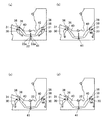
さらに搬送ローラ140が回転駆動されると、大径ディスク12は、バネ50,50の付勢力に抗しながら、ディスク再生装置10の内部に向かおうとする。なお、このとき、一対のロードアーム30,30は、図4、図6(a)、図7(a)に示すように、大径ディスク12の挿入に伴って、回動軸31,31を支点として、この回動軸31,31とともに互いの間隔を押し広げるように回動させられる。
また、回動軸31,31の回動に伴って、ロードアーム30とリンクレバー40とを連結している連結軸36は、前記連結軸ガイド溝38の第1連結軸ガイド溝38aを円弧を描くようにしてスライドする。
また、回動軸31,31の回動に伴って左右一対のリンクレバー40,40が、それらのリンク連結軸41がリンクガイド溝22を手前に向けてスライドするようにして、メインシャーシ20上をスライドする。なお、このときリンクレバー40,40はバネ50,50によって内側に付勢されている。
Further, when the transport roller 140 is driven to rotate, the large-diameter disk 12 tends to face the inside of the disk reproducing apparatus 10 against the urging force of the springs 50 and 50. At this time, as shown in FIGS. 4, 6A, and 7A, the pair of load arms 30 and 30 has the rotating shafts 31 and 31 as the large-diameter disk 12 is inserted. As a fulcrum, it is rotated with the rotating shafts 31 and 31 so as to widen the mutual distance.
Further, as the rotation shafts 31 and 31 rotate, the connection shaft 36 that connects the load arm 30 and the link lever 40 has a circular arc in the first connection shaft guide groove 38a of the connection shaft guide groove 38. Slide as you draw.
Further, as the pivot shafts 31 and 31 rotate, the pair of left and right link levers 40 and 40 are arranged on the main chassis 20 so that their link connecting shafts 41 slide toward the link guide groove 22 toward the front. Slide At this time, the link levers 40 and 40 are urged inward by the springs 50 and 50.

さらに、大径ディスク12の挿入に伴って回動軸31,31が回動することによって、図6(b)、図7(b)に示すように、リンク連結軸41がリンクガイド溝22の端部に位置してそれ以上のスライドが規制されることによって、回動軸31,31の回動によるロードアーム30,30の開き動作が終了する。しかし、ロードアーム30,30は未だ完全に開ききっていない。
そして、搬送ローラ140の回転駆動による、大径ディスク12のさらなる挿入に伴って、ロードアーム30,30には、該大径ディスク12によって、開くような力が作用する。
Further, when the rotary shafts 31 and 31 are rotated in accordance with the insertion of the large-diameter disk 12, the link connecting shaft 41 is connected to the link guide groove 22 as shown in FIGS. 6B and 7B. When the slide is further limited by being positioned at the end, the opening operation of the load arms 30 and 30 by the rotation of the rotation shafts 31 and 31 is completed. However, the load arms 30 and 30 are not fully opened yet.
Along with the further insertion of the large-diameter disk 12 by the rotational driving of the conveying roller 140, a force that opens by the large-diameter disk 12 acts on the load arms 30 and 30.

一方、リンク連結軸41がリンクガイド溝22の端部に位置したところで、連結軸36は第1連結軸ガイド溝38aから第2連結軸ガイド溝38bに移行する。すると、連結軸36が第2連結軸ガイド溝38bに沿ってスライド可能となるので、回動軸31は回動軸ガイド溝35の他方の端部に向けてスライド可能となる。
そして、図6(c)、(d)および図7(c)に示すように、回動軸31が回動軸ガイド溝35の他方の端部に向けてスライドすることによって、ロードアーム30はさらに外側に向けて開けるようになる。つまり、ロードアーム30,30には、該大径ディスク12によって、開くような力が作用しているので、これによって、ロードアーム30,30は、回動軸31,31が外側にスライドすることによって完全に大きく開く。
On the other hand, when the link connecting shaft 41 is positioned at the end of the link guide groove 22, the connecting shaft 36 moves from the first connecting shaft guide groove 38a to the second connecting shaft guide groove 38b. Then, since the connecting shaft 36 can slide along the second connecting shaft guide groove 38 b, the rotating shaft 31 can slide toward the other end of the rotating shaft guide groove 35.
Then, as shown in FIGS. 6C, 6D, and 7C, when the rotation shaft 31 slides toward the other end of the rotation shaft guide groove 35, the load arm 30 is It can be opened outward. That is, since the opening force is applied to the load arms 30 and 30 by the large-diameter disk 12, the load arms 30 and 30 cause the rotation shafts 31 and 31 to slide outward. Open completely wide.

そして、ロードアーム30,30が完全に開いた後、押し込みが所定だけ進行すると、大径ディスク12の奥側の外周縁部が、イジェクトアーム80のディスク保持部84とロードアーム30,30のディスク保持部34,34の3箇所で保持されて搬送可能な状態となる。(図5参照)。
搬送ローラ140,140の駆動により、大径ディスク12が奥側に向かって押し込まれると、リンク連結軸41が連結ガイド溝65の手前側の端部の近傍に位置する状態となる。このとき、不図示のトリガ機構が作動し、一のギヤと他のギヤとが噛み合う。すると、ローディングギヤ輪列70が駆動力を伝達可能な状態となり、ローディングギヤ輪列70の最終段のギヤ70aに噛み合っている外周ギヤ61に、駆動力が伝達される。
Then, after the load arms 30 and 30 are completely opened, when the push-in proceeds by a predetermined amount, the outer peripheral edge portion on the back side of the large-diameter disk 12 becomes the disk holding portion 84 of the eject arm 80 and the disk of the load arm 30 and 30. The holding units 34 and 34 are held at three locations and can be transported. (See FIG. 5).
When the large-diameter disk 12 is pushed toward the back side by driving the transport rollers 140 and 140, the link connecting shaft 41 is positioned in the vicinity of the end portion on the near side of the connecting guide groove 65. At this time, a trigger mechanism (not shown) is operated, and one gear and the other gear mesh. As a result, the loading gear train 70 can transmit the driving force, and the driving force is transmitted to the outer peripheral gear 61 that meshes with the gear 70 a at the final stage of the loading gear train 70.

トリガ機構が作動すると、ドライブカム60は、図5における左側(矢示A方向)に向かう摺動を開始する。この摺動により、リンク連結軸41は、大径ディスク用カム溝63のうち、送り込みカム部63aの内部を進行してゆく。すると、リンク連結軸41は、バネ部材50の付勢力または送り込みカム部63aの内壁によって押し込まれ、ドライブカム60が左側に向かって移動するにつれてディスク再生装置10の奥側に向かって移動する。この移動により、リンクレバー40の基端部も奥側に向かって移動させられる。リンク連結軸41が奥側に向かって移動する場合、連結軸36の位置は、ディスク保持部34,34を互いに近接する向きに向かって回動させる位置に移動する。
このようにして、ドライブカム60が左側にスライドするにつれて、ディスク保持部34,34が互いに近づく向きにロードアーム30,30は回動される。このとき、搬送ローラ140,140も回転駆動しているため、該搬送ローラ140,140の回転駆動と共に、ディスク保持部34,34の回動によっても、大径ディスク12は、ディスク再生装置10の内部に送り込まれていく。このとき、大径ディスク12は、イジェクトアーム80を介して排出バネ86により与えられる付勢力に抗しながら、ディスク再生装置10の奥側に向かって進行する。
When the trigger mechanism is actuated, the drive cam 60 starts sliding toward the left side (in the direction of arrow A) in FIG. By this sliding, the link connecting shaft 41 advances in the feeding cam portion 63a in the large-diameter disk cam groove 63. Then, the link connecting shaft 41 is pushed in by the urging force of the spring member 50 or the inner wall of the feeding cam portion 63a, and moves toward the back side of the disc reproducing apparatus 10 as the drive cam 60 moves toward the left side. By this movement, the base end portion of the link lever 40 is also moved toward the back side. When the link connecting shaft 41 moves toward the back side, the position of the connecting shaft 36 moves to a position where the disk holding portions 34 and 34 are rotated in the directions approaching each other.
In this way, as the drive cam 60 slides to the left, the load arms 30 and 30 are rotated so that the disk holding portions 34 and 34 approach each other. At this time, since the transport rollers 140 and 140 are also rotationally driven, the large-diameter disk 12 is moved by the rotation of the disk holding portions 34 and 34 together with the rotational driving of the transport rollers 140 and 140. It is sent inside. At this time, the large-diameter disk 12 advances toward the back side of the disk reproducing apparatus 10 while resisting the urging force given by the discharge spring 86 via the eject arm 80.

ドライブカム60が所定だけ左側にスライドすると、リンク連結軸41は、送り込みカム部63aを外れて、保持カム部63bに入り込む。このとき、大径ディスク12は、その中心がターンテーブル101の上部に位置していて、ディスククランプが可能な状態(センタリング状態)となっている。かかるセンタリング状態においては、搬送ローラ140,140は、大径ディスク12の図1等における投影面(この場合、大径ディスク12の法線方向における投影面)に差し掛かっていない。すなわち、大径ディスク12は、搬送ローラ140,140と干渉しない状態となっている。   When the drive cam 60 slides to the left by a predetermined amount, the link connecting shaft 41 disengages the feed cam portion 63a and enters the holding cam portion 63b. At this time, the center of the large-diameter disk 12 is located on the upper part of the turntable 101, and the disk can be clamped (centering state). In such a centering state, the conveying rollers 140 and 140 do not reach the projection surface of the large-diameter disk 12 in FIG. 1 or the like (in this case, the projection surface in the normal direction of the large-diameter disk 12). That is, the large-diameter disk 12 is in a state where it does not interfere with the transport rollers 140 and 140.

そして、保持カム部63bにリンク連結軸41が入り込んでいる間に、不図示の昇降機構が作動して、トラバースユニット90を上昇させる。それにより、ターンテーブル101の凸部分102が大径ディスク12の中心孔に差し込まれ、大径ディスク12のチャッキングが完了する。   Then, while the link connecting shaft 41 enters the holding cam portion 63b, a lifting mechanism (not shown) operates to raise the traverse unit 90. Thereby, the convex portion 102 of the turntable 101 is inserted into the center hole of the large-diameter disk 12, and the chucking of the large-diameter disk 12 is completed.

また、チャッキングが完了し、さらにドライブカム60が所定だけスライドすると、リンク連結軸41は、保持カム部63bを外れて逃がしカム部63cに入り込む。この逃がしカム部63cにリンク連結軸41が入り込むと、リンク連結軸41は、逃がしカム部63cの奥側の内壁に押されて、手前側に向けてスライドさせられる。すると、リンク連結軸41の手前側への移動に伴なって、ディスク保持部34,34が互いに離間するように、ロードアーム30が回動させられる。また、ドライブカム60の第1ホールド部66aは、解除レバー部85に衝突し、この解除レバー部85を徐々に押し込んでいく。   Further, when the chucking is completed and the drive cam 60 further slides by a predetermined amount, the link connecting shaft 41 is released from the holding cam portion 63b and enters the cam portion 63c. When the link connecting shaft 41 enters the relief cam portion 63c, the link connecting shaft 41 is pushed by the inner wall on the back side of the relief cam portion 63c and is slid toward the front side. Then, with the movement of the link connecting shaft 41 toward the front side, the load arm 30 is rotated so that the disk holding portions 34 and 34 are separated from each other. Further, the first hold portion 66a of the drive cam 60 collides with the release lever portion 85 and gradually pushes the release lever portion 85.

そして、リンク連結軸41が逃がしカム部63cを外れて、解除維持カム部63dに入り込んで、その右側端部まで移動すると、第1ホールド部66aは解除レバー部85を押し込んで、それによりイジェクトアーム80が回動させられ、ディスク保持部84が大径ディスク12の外周縁部に当接しない状態となる。これと共に、ディスク保持部34,34が大径ディスク12の外周縁部を保持している状態も解除され、ディスク保持部34,34,84と大径ディスク12とが接触しない状態となる。   Then, when the link connecting shaft 41 is released from the escape cam portion 63c, enters the release maintaining cam portion 63d and moves to the right end thereof, the first hold portion 66a pushes the release lever portion 85, thereby ejecting arm. 80 is rotated, and the disk holding portion 84 is not in contact with the outer peripheral edge of the large-diameter disk 12. At the same time, the state in which the disk holding portions 34, 34 hold the outer peripheral edge of the large-diameter disk 12 is also released, and the disk holding portions 34, 34, 84 and the large-diameter disk 12 are not in contact with each other.

なお、ディスク保持部34,34,84が接触しない状態になるのと共に、トラバースユニット90は、ドライブカム60の動作に伴なう不図示の昇降機構により、大径ディスク12の再生位置まで移動させられる。また、解除維持カム部63dにリンク連結軸41が入り込んで、ドライブカム60のスライドの左側の終点に近づく場合、ドライブカム60は、メインシャーシ20に存在する不図示の位置検出スイッチを押し込む。それにより、ローディングモータ71の駆動が停止され、ドライブカム60のスライド動作が終了する。
この後に、スピンドルモータ100が駆動することにより、ターンテーブル101が回転され、同時に光ピックアップ95が作動することにより、大径ディスク12に記録されている情報の読み取りによるディスク再生が可能となる。
The disk holding portions 34, 34, and 84 are not in contact with each other, and the traverse unit 90 is moved to the reproduction position of the large-diameter disk 12 by an elevating mechanism (not shown) that accompanies the operation of the drive cam 60. It is done. Further, when the link connecting shaft 41 enters the release maintaining cam portion 63 d and approaches the end point on the left side of the slide of the drive cam 60, the drive cam 60 pushes in a position detection switch (not shown) existing in the main chassis 20. Thereby, the driving of the loading motor 71 is stopped, and the sliding operation of the drive cam 60 is finished.
Thereafter, when the spindle motor 100 is driven, the turntable 101 is rotated, and at the same time, the optical pickup 95 is operated, so that the disk can be reproduced by reading the information recorded on the large diameter disk 12.

続いて、大径ディスク12を排出する場合の作用(動作)について説明する。この場合、まず、ユーザが不図示のイジェクトボタンを押し込む等により、ローディングモータ71には、排出に対応する回転を行うための電流が印加される。それにより、ローディングギヤ輪列70も駆動され、ローディングギヤ輪列70の最終段のギヤ70aに噛み合っている外周ギヤ61に、上述の向きとは逆の駆動力が伝達される。
なお、上述のようなローディングモータ71の作動により、ローラギヤ輪列150も回転駆動させられる。ここで、大径ディスク12が手前側に向かってスライドする前の状態においては、大径ディスク12は、搬送ローラ140,140に差し掛かっていない。そのため、この状態においては、搬送ローラ140,140は、ローラギヤ輪列150を介しての駆動力の伝達により、大径ディスク12を排出する向きの空転状態となる。
Subsequently, an operation (operation) when the large-diameter disk 12 is ejected will be described. In this case, first, when the user pushes an unillustrated eject button or the like, the loading motor 71 is applied with a current for performing rotation corresponding to the discharge. As a result, the loading gear train 70 is also driven, and a driving force opposite to the above-described direction is transmitted to the outer peripheral gear 61 meshed with the final gear 70a of the loading gear train 70.
The roller gear train 150 is also driven to rotate by the operation of the loading motor 71 as described above. Here, in a state before the large-diameter disk 12 slides toward the near side, the large-diameter disk 12 does not reach the conveying rollers 140 and 140. Therefore, in this state, the conveying rollers 140 and 140 are in an idling state in which the large-diameter disk 12 is ejected by transmission of the driving force via the roller gear train 150.

上述のようにしてドライブカム60に駆動力が伝達されると、該ドライブカム60は右側に向かうスライドを開始する。ここで、このスライドに先立って、またはこのスライドと共に、トラバースユニット90は、不図示の昇降機構により、大径ディスク12のチャッキング解除を行える位置に移動させられる。
この状態となった後に、ドライブカム60が右側に向かってスライドしていくことで、リンク連結軸41が解除維持カム部63dから逃がしカム部63cに入り込み、さらに、
保持カム部63bから、送り込みカム部63aに入り込む。このようなリンク連結軸41の移動に伴なって、ロードアーム30は、リンクレバー40を介して、ディスク保持部34,34が互いに離れる向きに回動させられる。そして、大径ディスク12は、イジェクトアーム80を介しての排出バネ86の付勢力により、ディスク保持部34,34が徐々に互いに離れていくと、手前側に向かって徐々に押し出されてゆく。
ここで、大径ディスク12が手前側に向かって押し出されていくと、該大径ディスク12裏面の左右側かつ手前側の一部が、搬送ローラ140,140に接触する状態となる。ここで、搬送ローラ140,140は、上述のように、大径ディスク12を排出する向きに向かって空転している。このため、大径ディスク12の一部が搬送ローラ140,140に接触すると、搬送ローラ140,140は、イジェクトアーム80と共に、大径ディスク12を手前側に向けて排出させようとする。
そして、所定だけイジェクトアーム80が回動した後に、解除レバー部85がアーム検出スイッチ110を押し込む。それにより、ローディングモータ71の駆動が停止させられる。
When the driving force is transmitted to the drive cam 60 as described above, the drive cam 60 starts sliding toward the right side. Here, prior to or together with this slide, the traverse unit 90 is moved to a position where the chucking of the large-diameter disk 12 can be released by an elevating mechanism (not shown).
After this state is reached, the drive cam 60 slides to the right, so that the link connecting shaft 41 escapes from the release maintaining cam portion 63d and enters the cam portion 63c.
From the holding cam portion 63b, the feed cam portion 63a enters. As the link connecting shaft 41 moves, the load arm 30 is rotated via the link lever 40 in a direction in which the disk holding portions 34 and 34 are separated from each other. The large-diameter disk 12 is gradually pushed out toward the front side when the disk holding portions 34 and 34 are gradually separated from each other by the biasing force of the discharge spring 86 via the eject arm 80.
Here, when the large-diameter disk 12 is pushed out toward the near side, the left and right sides and a part on the near side of the back surface of the large-diameter disk 12 come into contact with the transport rollers 140 and 140. Here, the transport rollers 140 and 140 are idled in the direction in which the large-diameter disk 12 is ejected as described above. For this reason, when a part of the large-diameter disk 12 comes into contact with the transport rollers 140 and 140, the transport rollers 140 and 140 try to eject the large-diameter disk 12 toward the front side together with the eject arm 80.
Then, after the eject arm 80 rotates by a predetermined amount, the release lever portion 85 pushes the arm detection switch 110. Thereby, the driving of the loading motor 71 is stopped.

上記のような大径ディスク12の排出動作の際において、大径ディスク12の挿入動作と同様にしてアーム開閉機構が作用する。
すなわち、大径ディスク12を搬送ローラ140,140によってディスク再生装置10の外部に向けて排出すると、該大径ディスク12の外周縁部には、左右のロードアーム30,30の先端部のディスク保持部34,34が当接しているので、このディスク保持部34,34を大径ディスク12が押すことによって、ロードアーム30,30はその先端部のディスク保持部34,34が離間するように回動させられる。
When the large-diameter disk 12 is ejected as described above, the arm opening / closing mechanism acts in the same manner as the large-diameter disk 12 is inserted.
That is, when the large-diameter disk 12 is ejected toward the outside of the disk reproducing apparatus 10 by the conveying rollers 140 and 140, the outer peripheral edge of the large-diameter disk 12 is held by the disk at the tip of the left and right load arms 30 and 30. Since the large-diameter disk 12 pushes the disk holding parts 34, 34, the load arms 30, 30 are rotated so that the disk holding parts 34, 34 at the leading ends thereof are separated from each other. Be moved.

さらに搬送ローラ140,140が回転駆動されると、大径ディスク12は、バネ50,50の付勢力に抗しながら、ディスク再生装置10の外部に向かおうとする。なお、このとき、一対のロードアーム30,30は、大径ディスク12の排出に伴って、回動軸31,31を支点として、この回動軸31,31とともに互いの間隔を押し広げるように回動させられる。
また、回動軸31,31の回動に伴って、ロードアーム30とリンクレバー40とを連結している連結軸36は、前記連結軸ガイド溝38の第1連結軸ガイド溝38aを円弧を描くようにしてスライドする。
また、回動軸31,31の回動に伴って左右一対のリンクレバー40,40が、それらのリンク連結軸41がリンクガイド溝22を手前に向けてスライドするようにして、メインシャーシ20上をスライドする。なお、このときリンクレバー40,40はバネ50,50によって内側に付勢されている。
When the conveying rollers 140 and 140 are further driven to rotate, the large-diameter disk 12 tends to go outside the disk reproducing apparatus 10 against the urging force of the springs 50 and 50. At this time, as the pair of load arms 30 and 30 are ejected from the large-diameter disk 12, the rotation shafts 31 and 31 are used as fulcrums and the mutual distance between the pair of load arms 30 and 31 is increased. It can be rotated.
Further, as the rotation shafts 31 and 31 rotate, the connection shaft 36 that connects the load arm 30 and the link lever 40 has a circular arc in the first connection shaft guide groove 38a of the connection shaft guide groove 38. Slide as you draw.
Further, as the pivot shafts 31 and 31 rotate, the pair of left and right link levers 40 and 40 are arranged on the main chassis 20 so that their link connecting shafts 41 slide toward the link guide groove 22 toward the front. Slide At this time, the link levers 40 and 40 are urged inward by the springs 50 and 50.

さらに、大径ディスク12の排出に伴って回動軸31,31が回動することによって、リンク連結軸41がリンクガイド溝22の端部に位置してそれ以上のスライドが規制されることによって、回動軸31,31の回動によるロードアーム30,30の開き動作が終了する。しかし、ロードアーム30,30は未だ完全に開ききっていない。
そして、搬送ローラ140の回転駆動による、大径ディスク12のさらなる排出に伴って、ロードアーム30,30には、該大径ディスク12によって、開くような力が作用する。
Further, when the rotary shafts 31 and 31 are rotated as the large-diameter disk 12 is discharged, the link connecting shaft 41 is positioned at the end of the link guide groove 22 and further slide is restricted. Then, the opening operation of the load arms 30, 30 by the rotation of the rotation shafts 31, 31 is completed. However, the load arms 30 and 30 are not fully opened yet.
As the large-diameter disk 12 is further discharged by the rotation of the conveying roller 140, a force that opens the large-diameter disk 12 acts on the load arms 30 and 30.

一方、リンク連結軸41がリンクガイド溝22の端部に位置したところで、連結軸36は第1連結軸ガイド溝38aから第2連結軸ガイド溝38bに移行する。すると、連結軸36が第2連結軸ガイド溝38bに沿ってスライド可能となるので、回動軸31は回動軸ガイド溝35の他方の端部に向けてスライド可能となる。
そして、回動軸31が回動軸ガイド溝35の他方の端部に向けてスライドすることによって、ロードアーム30はさらに外側に向けて開けるようになる。つまり、ロードアーム30,30には、該大径ディスク12によって、開くような力が作用しているので、これによって、ロードアーム30,30は、回動軸31,31が外側にスライドすることによって完全に大きく開く。したがって、大径ディスク12を容易に排出できる。
On the other hand, when the link connecting shaft 41 is positioned at the end of the link guide groove 22, the connecting shaft 36 moves from the first connecting shaft guide groove 38a to the second connecting shaft guide groove 38b. Then, since the connecting shaft 36 can slide along the second connecting shaft guide groove 38 b, the rotating shaft 31 can slide toward the other end of the rotating shaft guide groove 35.
Then, when the rotation shaft 31 slides toward the other end of the rotation shaft guide groove 35, the load arm 30 can be opened further outward. That is, since the opening force is applied to the load arms 30 and 30 by the large-diameter disk 12, the load arms 30 and 30 cause the rotation shafts 31 and 31 to slide outward. Open completely wide. Therefore, the large diameter disk 12 can be easily discharged.

本実施の形態によれば、メインシャーシ20に、回動軸31をスライド可能とする回動軸ガイド溝35と、リンク連結軸41がリンクガイド溝22をスライドする範囲では連結軸36を回動軸31回りに回動可能とするとともに回動軸31を固定状態とし、リンク連結軸41がリンクガイド溝22の端部に位置してそれ以上のスライドが規制された際に、左右一対のロードアーム30,30の先端部をさらに離間させるべく回動軸31をスライド可能とするように、連結軸36を移動可能とする連結軸ガイド溝38が形成されているので、リンク連結軸41がリンクガイド溝22の端部に位置してそれ以上のスライドが規制された際に、回動軸31が回動軸ガイド溝35に沿ってスライド動作することができる。
したがって、メインシャーシ20に形成するリンクガイド溝22を長くすることなく、左右一対のロードアーム30,30を大きく開くことができる。したがって、コンパクト化を図れるとともに左右一対のロードアーム30,30の開き量を確保できる。
According to the present embodiment, the rotation shaft guide groove 35 that allows the rotation shaft 31 to slide on the main chassis 20 and the connection shaft 36 rotate within the range in which the link connection shaft 41 slides on the link guide groove 22. A pair of left and right loads when the rotation shaft 31 is fixed and the link connecting shaft 41 is positioned at the end of the link guide groove 22 and further sliding is restricted. Since the connecting shaft guide groove 38 that allows the connecting shaft 36 to move is formed so that the rotating shaft 31 can be slid so as to further separate the distal ends of the arms 30 and 30, the link connecting shaft 41 is linked to the link shaft 41. When the further slide is restricted at the end of the guide groove 22, the rotation shaft 31 can slide along the rotation shaft guide groove 35.
Therefore, the pair of left and right load arms 30, 30 can be greatly opened without lengthening the link guide groove 22 formed in the main chassis 20. Therefore, it is possible to achieve a compact size and secure an opening amount of the pair of left and right load arms 30 and 30.

また、メインシャーシ20に、左右一対のリンクレバー40,40を、左右一対のロードアーム30,30の先端部が接近するように付勢するバネ(第1付勢部材)50,50が設けられているので、大径ディスク12を挿入および排出する際に、該大径ディスク12の外周縁部にディスク保持部34,34を弾性的に押圧した状態で確実に当接させることができる。したがって、大径ディスク12の挿入および排出動作がより安定的となる。
さらに、バネ50,50は、連結軸36,36が第2連結軸ガイド溝38b,38bに沿ってスライドしてさらに大きく開いたロードアーム30,30を、その先端部が接近するように付勢しているので、この点においても大径ディスク12の挿入および排出動作がより安定的となる。
また、リンクガイド溝22に、一対の切欠部22a,22aがリンクガイド溝22の幅方向に対向して形成されているので、左右一対のロードアーム30,30のうちの一方のロードアーム30に、搬送される最中に若干左右方向にずれたディスク12から力が作用した場合、リンク連結軸41が一方の切欠部22aに入り込んでそれ以上のリンク連結軸41のスライドを阻止し、他方のロードアーム30にディスク12から力が作用したときに、リンク連結軸41が前記切欠部22aから外れて、再びリンクガイド溝22をスライドする。したがって、ディスク12の挿入、排出の際に、左右一対のロードアーム30,30の一方のみが当接したままの状態で挿入、排出動作がなされることがなく、挿入および排出動作がさらに安定的となる。
このため、小径ディスクがディスク口の端の方から挿入されても、3点による保持による搬送ができなくなるようなことを防止することができる。
The main chassis 20 is provided with springs (first urging members) 50 and 50 for urging the pair of left and right link levers 40 and 40 so that the tip ends of the pair of left and right load arms 30 and 30 approach each other. Therefore, when the large-diameter disk 12 is inserted and ejected, the outer periphery of the large-diameter disk 12 can be reliably brought into contact with the disk holding portions 34 and 34 being elastically pressed. Therefore, the insertion and ejection operation of the large diameter disk 12 becomes more stable.
Further, the springs 50 and 50 bias the load arms 30 and 30 that are further opened by sliding the connecting shafts 36 and 36 along the second connecting shaft guide grooves 38b and 38b so that the tip ends thereof approach each other. Therefore, the insertion and ejection operations of the large-diameter disk 12 are more stable in this respect as well.
Further, since the pair of cutout portions 22 a and 22 a are formed in the link guide groove 22 so as to face each other in the width direction of the link guide groove 22, one of the pair of left and right load arms 30 and 30 is provided with one load arm 30. When a force is applied from the disc 12 slightly shifted in the left-right direction during the conveyance, the link connecting shaft 41 enters one of the cutout portions 22a and prevents the link connecting shaft 41 from sliding further, When force is applied to the load arm 30 from the disk 12, the link connecting shaft 41 is disengaged from the notch 22a and slides in the link guide groove 22 again. Therefore, when the disk 12 is inserted and ejected, the insertion and ejection operations are not performed with only one of the pair of left and right load arms 30 and 30 being in contact with each other, and the insertion and ejection operations are further stable. It becomes.
For this reason, even if a small-diameter disk is inserted from the end of the disk opening, it is possible to prevent the conveyance by holding by three points from being disabled.

加えて、搬送ローラ140,140が左右一対配置されているので、ディスクaの左右両側に搬送ローラ140,140を均一に当接でき、よって、ディスク12を確実に真っ直ぐに挿入、排出できる。
また、ディスク12は、一対のロードアーム30,30、イジェクトアーム80によって、その外周縁部が保持される。このため、ディスク再生装置10の奥側では、ディスク12を、ロードアーム30,30、イジェクトアーム80によって保持されながら、安定的に搬送/保持可能となる。
また、搬送ローラ140,140は、ディスク12の投影面の外側に設けられているので、ディスク12のチャッキング等に際して、ディスク12と搬送ローラ140,140とが干渉しない。それにより、搬送ローラを用いてディスク12を搬送する方式と比較して、該ローラの退避等のために、搬送ローラを上下動させるための機構が不要となる。そのため、ローディング機構の単純化を図ることが可能となる。
In addition, since the pair of left and right transport rollers 140 and 140 are arranged, the transport rollers 140 and 140 can be uniformly abutted on both the left and right sides of the disk a, so that the disk 12 can be surely inserted and discharged straight.
The outer peripheral edge of the disk 12 is held by a pair of load arms 30 and 30 and an eject arm 80. For this reason, the disk 12 can be stably conveyed / held while being held by the load arms 30 and 30 and the eject arm 80 on the back side of the disk reproducing apparatus 10.
Further, since the transport rollers 140 and 140 are provided outside the projection surface of the disk 12, the disk 12 and the transport rollers 140 and 140 do not interfere when the disk 12 is chucked. As a result, a mechanism for moving the transport roller up and down is not required for retraction of the disk, etc., as compared with the method of transporting the disk 12 using the transport roller. Therefore, the loading mechanism can be simplified.

さらに、ディスク再生装置10の手前側の部分に、搬送ローラ140,140が設けられている。そのため、ディスク再生装置10の内部に差し込まれるディスク12の差し込み量が少なくても、搬送ローラ140,140の駆動によってディスク12をディスク再生装置10の奥側まで搬入させることが可能となる。また、ディスク12をディスク再生装置10の内部から排出させる場合でも、十分な排出量を得ることが可能となる。そのため、ディスク12の差し込み動作および取り出し動作が楽になり、ユーザにとって、ディスク再生装置10の使い勝手が良好となる。
また、搬送ローラ140,140の駆動によりディスク12を排出するが、このとき、イジェクトアーム80の回動により、解除レバー部85がアーム検出スイッチ110を押し込み、ローディングモータ71の駆動を停止させる構成を採用している。このため、ディスク12の排出量が安定的となり、ディスク12の排出位置がバラ付くのを抑えることが可能となる。
また、上述のディスク再生装置10では、大径ディスク12か小径ディスク12かによって、ロードアーム30の回動範囲が定まり、このロードアーム30の回動範囲の相違により、ディスクガイド溝62のうち、リンク連結軸41が進行する経路が切り替わるように構成されている。すなわち、大径ディスク12の場合には、大径ディスク用カム溝63の内部を、小径ディスク12の場合には、小径ディスク用カム溝64の内部をリンク連結軸41が進行する。
Further, conveyance rollers 140 and 140 are provided on the front side of the disk reproducing apparatus 10. Therefore, even if the insertion amount of the disk 12 inserted into the disk reproducing apparatus 10 is small, the disk 12 can be carried into the inner side of the disk reproducing apparatus 10 by driving the transport rollers 140 and 140. Even when the disc 12 is ejected from the inside of the disc reproducing apparatus 10, a sufficient ejection amount can be obtained. Therefore, the operation of inserting and removing the disk 12 is facilitated, and the usability of the disk reproducing apparatus 10 is improved for the user.
Further, the disk 12 is ejected by driving the transport rollers 140, 140. At this time, the release lever portion 85 pushes the arm detection switch 110 by the rotation of the eject arm 80, and the driving of the loading motor 71 is stopped. Adopted. For this reason, the discharge amount of the disk 12 becomes stable, and it becomes possible to suppress variations in the discharge position of the disk 12.
Further, in the above-described disc reproducing apparatus 10, the rotation range of the load arm 30 is determined depending on whether the large-diameter disc 12 or the small-diameter disc 12. Due to the difference in the rotation range of the load arm 30, The path along which the link connecting shaft 41 travels is switched. That is, in the case of the large-diameter disk 12, the link connecting shaft 41 advances through the inside of the large-diameter disk cam groove 63, and in the case of the small-diameter disk 12, the link connecting shaft 41 advances through the inside of the small-diameter disk cam groove 64.

かかる構成のため、ロードアーム30の回動範囲の相違だけで、ディスク12が大径ディスク12であるか小径ディスク12であるか、自動的に判別されるのと等しい状態となる。それにより、ディスク12の直径を判別するための、電気的な判別手段を用いずに済み、接触不良等が生じないため、動作の信頼性を高めることが可能となる。また、ディスク12の直径の判別のためにスイッチ等を用いずに済み、その分だけコストを低減することが可能となる。さらに、ディスク12の直径の判別のためにスイッチ等を用いずに済むことで、制御プログラムが簡略化でき、ディスク12のローディング時における動作の信頼性を高めることが可能となる。   Due to such a configuration, only the difference in the rotation range of the load arm 30 is equivalent to automatically discriminating whether the disk 12 is the large diameter disk 12 or the small diameter disk 12. Thereby, it is not necessary to use an electrical discriminating means for discriminating the diameter of the disk 12, and no contact failure or the like occurs, so that the operation reliability can be improved. Further, it is not necessary to use a switch or the like for discriminating the diameter of the disk 12, and the cost can be reduced accordingly. Furthermore, since it is not necessary to use a switch or the like for discriminating the diameter of the disk 12, the control program can be simplified, and the reliability of the operation when loading the disk 12 can be improved.

また、イジェクトアーム80を具備し、このイジェクトアーム80には、排出バネ86によりディスク12を排出する向きの付勢力が与えられている。かかる排出バネ86の付勢力を利用すると共に、リンク連結軸41がディスクガイド溝62の内壁に押し付けられる等によってロードアーム30の回動が規制されるため、ディスク保持部34,34,84の間で、ディスク12の保持を確実に行うことが可能となる。   Further, an eject arm 80 is provided, and an urging force in the direction of ejecting the disk 12 is given to the eject arm 80 by a discharge spring 86. Since the urging force of the discharge spring 86 is used and the link connecting shaft 41 is pressed against the inner wall of the disk guide groove 62, the rotation of the load arm 30 is restricted. Thus, the disk 12 can be securely held.

さらに、上述のように、ディスク保持部34,34,84によりディスク12を保持するに際して、ディスク12とディスク保持部34,34,84との接触点を結ぶ図形(三角形)の内部に、ディスク12の中心が位置するようにしている。このようにすれば、ディスク保持部84を介して与えられる排出バネ86等の付勢力等を、ディスク保持部34,34等で受け止めることが可能となり、ディスク12の保持を確実に行わせることが可能となる。   Further, as described above, when the disc 12 is held by the disc holding portions 34, 34, 84, the disc 12 is placed inside the figure (triangle) connecting the contact points between the disc 12 and the disc holding portions 34, 34, 84. The center of is located. In this way, it is possible to receive the urging force of the discharge spring 86 and the like applied via the disk holding portion 84 by the disk holding portions 34 and 34 and the like, and the disk 12 can be reliably held. It becomes possible.

また、一対のロードアーム30,30は、リンクレバー40,40およびリンク連結軸41を介して、互いに連動するように接合されている。このため、ディスク12の搬送に際して、一対のロードアーム30,30は、互いの連動により同時に開閉動作を行える状態となり、ディスク12に対して幅方向の両側から当接/開閉動作を行える。それにより、ディスク12に対する片当たり等で、ディスク12が一方側に片寄るのを防止することが可能となる。それによって、ディスク12の良好な搬送を行うことが可能となる。   The pair of load arms 30 and 30 are joined to each other via the link levers 40 and 40 and the link connecting shaft 41. Therefore, when the disk 12 is transported, the pair of load arms 30 and 30 can be opened / closed simultaneously by interlocking with each other, and can contact / open / close the disk 12 from both sides in the width direction. Accordingly, it is possible to prevent the disk 12 from being shifted to one side, for example, when the disk 12 is in contact with each other. As a result, the disk 12 can be transported satisfactorily.

さらに、一対のリンクレバー40,40、および一対のリンクレバー40,40を連結するリンク連結軸41により、リンク機構は構成されている。そのため、リンク連結軸41のリンクガイド溝22における摺動、およびこの摺動に伴なうリンクレバー40,40の連動により、ロードアーム30の回動位置を一義的に定めることが可能となり、ディスク12の確実な保持および送り込みを行わせることが可能となる。   Further, the link mechanism is configured by a pair of link levers 40 and 40 and a link connecting shaft 41 that connects the pair of link levers 40 and 40. Therefore, the rotation position of the load arm 30 can be uniquely determined by the sliding of the link connecting shaft 41 in the link guide groove 22 and the interlocking of the link levers 40, 40 accompanying the sliding. 12 can be reliably held and fed.

(第2の実施の形態)
図8は本発明に係るアーム開閉機構の第2の実施の形態を示すものである。この第2の実施の形態では、アーム開閉機構のみを説明し、アーム開閉機構以外の、ディスク再生装置の構成については図示とその説明を省略する。なお、アーム開閉機構以外の、ディスク再生装置の構成は第1の実施の形態と同様である。
(Second Embodiment)
FIG. 8 shows a second embodiment of an arm opening / closing mechanism according to the present invention. In the second embodiment, only the arm opening / closing mechanism will be described, and the illustration and description of the configuration of the disk reproducing apparatus other than the arm opening / closing mechanism will be omitted. The configuration of the disk reproducing apparatus other than the arm opening / closing mechanism is the same as that of the first embodiment.

メインシャーシ20には、左右一対のロードアーム30,30が配置されており、これら左右一対のロードアーム30,30は、左右一対の回動軸31,31に、それぞれの中途部が取り付けられている。
また、ロードアーム30は、軸支持部32と、アーム部33と、ディスク保持部34とを有している。
The main chassis 20 is provided with a pair of left and right load arms 30, 30. These pair of left and right load arms 30, 30 are respectively attached to a pair of left and right rotating shafts 31, 31 with respective midway portions. Yes.
The load arm 30 includes a shaft support part 32, an arm part 33, and a disk holding part 34.

軸支持部32はロードアーム30の中途部に形成されており、この軸支持部32に回動軸31が挿通固定され、この回動軸31がメインシャーシ20に回動可能に取り付けられることによって、ロードアーム30がメインシャーシ20に対して回動可能に設けられている。
メインシャーシ20には、回動軸31をスライド可能とする回動軸ガイド溝55が形成されている。この回動軸ガイド溝55は円弧状のもので、メインシャーシ20の左右端部側でかつ手前側にそれぞれ形成されている。この回動軸ガイド溝55の円弧の中心は後述する連結軸ガイド溝58の一方(手前側)の端部となっている。
また、前記ロードアーム30の基端部30aは、内方に向けて突出しており、この基端部30aに連結軸36が取り付けられている。
アーム部33は、回動軸31から、内方かつ手前側に向かって延伸している。
ディスク保持部34は、ディスク12の搬送時に、該ディスク12の外周縁部を保持するための部分である。
The shaft support portion 32 is formed in the middle of the load arm 30, and the rotation shaft 31 is inserted and fixed to the shaft support portion 32, and the rotation shaft 31 is rotatably attached to the main chassis 20. The load arm 30 is provided so as to be rotatable with respect to the main chassis 20.
A rotation shaft guide groove 55 that allows the rotation shaft 31 to slide is formed in the main chassis 20. The rotation shaft guide groove 55 has an arc shape, and is formed on the left and right ends of the main chassis 20 and on the front side. The center of the arc of the rotating shaft guide groove 55 is one end (front side) of a connecting shaft guide groove 58 described later.
Further, the base end portion 30a of the load arm 30 protrudes inward, and a connecting shaft 36 is attached to the base end portion 30a.
The arm portion 33 extends from the rotation shaft 31 inward and toward the front side.
The disk holding part 34 is a part for holding the outer peripheral edge of the disk 12 when the disk 12 is transported.

また、ロードアーム30の基端部30aには、リンクレバー40の先端部が連結されている。リンクレバー40は、ロードアーム30に対し、連結軸36を介して回動自在に連結されている。連結軸36はメインシャーシ20に形成された連結軸ガイド溝58にスライド可能に挿入されている。一対のリンクレバー40,40の基端部(連結軸36から離れる側の端部)は、ディスク再生装置10の幅方向の中央部分かつ手前側の部分において、互いに重なるように設けられている。この重なり状態を固定的とするため、リンクレバー40,40の基端部どうしは、互いにリンク連結軸41によって回動可能に連結されている。   Further, the distal end portion of the link lever 40 is connected to the proximal end portion 30 a of the load arm 30. The link lever 40 is rotatably connected to the load arm 30 via a connecting shaft 36. The connecting shaft 36 is slidably inserted into a connecting shaft guide groove 58 formed in the main chassis 20. The base end portions (end portions on the side away from the connecting shaft 36) of the pair of link levers 40, 40 are provided so as to overlap each other at the center portion in the width direction and the front side portion of the disc reproducing apparatus 10. In order to fix this overlapping state, the base end portions of the link levers 40 and 40 are connected to each other by a link connecting shaft 41 so as to be rotatable.

リンク連結軸41は、その下方側の部分がメインシャーシ20に設けられているリンクガイド溝22に入り込む。また、リンクガイド溝22は、リンク連結軸41の直径に対応した幅寸法に設定されていて、リンクガイド溝22の内部でリンク連結軸41をさほどガタ付かせないように設けられている。
また、リンクガイド溝22には、一対の切欠部22a,22aがリンクガイド溝22の幅方向に対向して形成されている。
The lower part of the link connecting shaft 41 enters the link guide groove 22 provided in the main chassis 20. Further, the link guide groove 22 is set to have a width corresponding to the diameter of the link connecting shaft 41 and is provided so that the link connecting shaft 41 is not so loose within the link guide groove 22.
The link guide groove 22 is formed with a pair of notches 22 a and 22 a so as to face each other in the width direction of the link guide groove 22.

そして、上記のようなリンク機構(アーム開閉機構)では、左右一対のロードアーム30,30がその先端部どうしを接離させるように回動軸31を支点として回動して開閉するに伴って、左右一対のリンクレバー40,40を介してリンク連結軸41がリンクガイド溝22をスライドするようになっている。
また逆に、リンク連結軸41がリンクガイド溝22をスライドすることによって、左右一対のリンクレバー40,40を介して左右一対のロードアーム30,30が同期して左右一対の回動軸31,31を支点として回動して開閉するようになっている。
In the link mechanism (arm opening / closing mechanism) as described above, as the pair of left and right load arms 30, 30 pivots around the pivot shaft 31 so as to bring the distal ends into contact with each other, the opening and closing are performed. The link connecting shaft 41 slides in the link guide groove 22 through a pair of left and right link levers 40, 40.
Conversely, when the link connecting shaft 41 slides in the link guide groove 22, the pair of left and right load arms 30, 30 are synchronized with each other via the pair of left and right link levers 40, 40. 31 is pivoted about a fulcrum and opens and closes.

さらに、上記のようなリンク機構では、メインシャーシ20に、左右一対のリンクレバー40,40を、左右一対のロードアーム30,30の先端部が接近するように付勢する第1付勢部材としてのバネ50,50が設けられている。バネ50の一端部はリンクレバー40に接続され、他端部はメインシャーシ20の固定的な部位に接続されている。
このバネ部材50により、リンク連結軸41には、ディスク再生装置10の奥側に向かう付勢力が与えられる。それにより、リンク連結軸41がリンクガイド溝22に位置している場合、リンク連結軸41を奥側に引き込む向きの付勢力を、リンク連結軸41に与えていて、それによってロードアーム30,30を閉じる向きに回動させている。
またメインシャーシ20には、左右一対のロードアーム30,30をその先端部どうしが接近するように付勢する第2付勢部材としてのバネ51,51が設けられている。このバネ51はねじりスプリングであり、その一端部は回動軸31に接続され、他端部はメインシャーシ20の固定的な部位に接続されている。このバネ51によって、ロードアーム30は前記連結軸ガイド溝58の一方の端部を中心として回動して接近するように付勢されている。なお、バネ51は引っ張りバネで構成することも可能である。
Further, in the link mechanism as described above, the pair of left and right link levers 40 and 40 are urged against the main chassis 20 as the first urging member that urges the distal ends of the pair of left and right load arms 30 and 30 to approach each other. Springs 50, 50 are provided. One end of the spring 50 is connected to the link lever 40, and the other end is connected to a fixed part of the main chassis 20.
By this spring member 50, an urging force toward the inner side of the disk reproducing device 10 is given to the link connecting shaft 41. As a result, when the link connecting shaft 41 is positioned in the link guide groove 22, an urging force in a direction to draw the link connecting shaft 41 to the back side is given to the link connecting shaft 41, thereby the load arms 30, 30. Is rotated in the closing direction.
Further, the main chassis 20 is provided with springs 51 and 51 as second urging members for urging the pair of left and right load arms 30 and 30 so that their tip portions approach each other. The spring 51 is a torsion spring, one end of which is connected to the rotating shaft 31 and the other end is connected to a fixed part of the main chassis 20. The spring 51 biases the load arm 30 so as to rotate and approach one end of the connecting shaft guide groove 58. The spring 51 can also be constituted by a tension spring.

また、上記のようなリンク機構では、前記回動軸31は、リンク連結軸41がリンクガイド溝22をスライドする範囲では固定されるとともに、リンク連結軸41がリンクガイド溝41の端部に位置してそれ以上のスライドが規制された際に、スライド可能となるように構成されている。
すなわちまず、前記連結軸ガイド溝58は回動軸31を中心とした円弧状に形成されている。
この連結軸ガイド溝58の円弧の中心は、回動軸ガイド溝55の一方の端部である、つまり回動軸31が回動軸ガイド溝55の一方の端部に位置している場合の回動軸31である。
回動軸ガイド溝55の一方の端部とは、該回動軸ガイド溝55の、リンクレバー40の基端部に近い側の端部である。
また、回動軸ガイド溝55の円弧の中心は連結軸ガイド溝58の一方(手前側)の端部となっている。
In the link mechanism as described above, the rotation shaft 31 is fixed in a range where the link connecting shaft 41 slides on the link guide groove 22, and the link connecting shaft 41 is positioned at the end of the link guide groove 41. When the slide is further restricted, it is configured to be slidable.
That is, first, the connecting shaft guide groove 58 is formed in an arc shape with the rotation shaft 31 as the center.
The center of the arc of the connecting shaft guide groove 58 is one end of the rotating shaft guide groove 55, that is, when the rotating shaft 31 is located at one end of the rotating shaft guide groove 55. This is a rotation shaft 31.
One end portion of the rotation shaft guide groove 55 is an end portion of the rotation shaft guide groove 55 on the side close to the base end portion of the link lever 40.
Further, the center of the arc of the rotation shaft guide groove 55 is one end (front side) of the connection shaft guide groove 58.

そして、リンク連結軸41がリンクガイド溝22をスライドする範囲では、連結軸36が連結軸ガイド溝58をスライドするので、回動軸31は固定されることになる。つまり、連結軸36が連結軸ガイド溝58をスライドする際は、該連結軸36は連結軸ガイド溝58の壁(回動軸31を中心とする平面視円弧状の壁)に当接しているので、回動軸31はロードアーム30によって回転軸ガイド溝55に沿ったスライドが規制される。回動軸31は回転軸ガイド溝35と直交する方向にはスライドできないので、回転軸ガイド溝35の一方の端部で固定されることになる。
一方、リンク連結軸41がリンクガイド溝22の端部に位置したところで、連結軸36は連結軸ガイド溝58の一方の端部に位置する。すると、回動軸31が回動軸ガイド溝55に沿ってスライド可能となるので、回動軸31は回動軸ガイド溝35の他方の端部に向けてスライド可能となる。つまり、前記回動軸31は、リンク連結軸41がリンクガイド溝22の端部に位置してそれ以上のスライドが規制された際に、スライド可能となるのである。
そして、回動軸31が回動軸ガイド溝35の他方の端部に向けてスライドすることによって、ロードアーム30は連結軸36を支点としてさらに外側に向けて開けるようになる。
In the range in which the link connecting shaft 41 slides in the link guide groove 22, the connecting shaft 36 slides in the connecting shaft guide groove 58, so that the rotating shaft 31 is fixed. That is, when the connecting shaft 36 slides in the connecting shaft guide groove 58, the connecting shaft 36 abuts against the wall of the connecting shaft guide groove 58 (the wall having an arc shape in plan view with the rotation shaft 31 as the center). Therefore, the slide of the rotating shaft 31 along the rotating shaft guide groove 55 is restricted by the load arm 30. Since the rotation shaft 31 cannot slide in the direction orthogonal to the rotation shaft guide groove 35, it is fixed at one end of the rotation shaft guide groove 35.
On the other hand, when the link connecting shaft 41 is located at the end of the link guide groove 22, the connecting shaft 36 is located at one end of the connecting shaft guide groove 58. Then, since the rotation shaft 31 can slide along the rotation shaft guide groove 55, the rotation shaft 31 can slide toward the other end of the rotation shaft guide groove 35. That is, the pivot shaft 31 can slide when the link connecting shaft 41 is positioned at the end of the link guide groove 22 and further sliding is restricted.
Then, when the rotation shaft 31 slides toward the other end of the rotation shaft guide groove 35, the load arm 30 can be opened further outward with the connecting shaft 36 as a fulcrum.

上記のような構成のリンク開閉機構では、ディスクをディスク再生装置の内部に向けて挿入すると、ロードアーム30,30の先端部のディスク保持部34,34が離間するように回動させられる。
そして、ディスクは、バネ50,50の付勢力に抗しながら、ディスク再生装置の内部に向かおうとする。なお、このとき、一対のロードアーム30,30は、大径ディスク12の挿入に伴って、回動軸31,31を支点として、この回動軸31,31とともに互いの間隔を押し広げるように回動させられる。
また、回動軸31,31の回動に伴って、ロードアーム30とリンクレバー40とを連結している連結軸36は、前記連結軸ガイド溝58を円弧を描くようにしてスライドする。
また、回動軸31,31の回動に伴って左右一対のリンクレバー40,40が、それらのリンク連結軸41がリンクガイド溝22を手前に向けてスライドするようにして、メインシャーシ20上をスライドする。なお、このときリンクレバー40,40はバネ50,50によって内側に付勢されている。
In the link opening / closing mechanism configured as described above, when the disc is inserted toward the inside of the disc reproducing apparatus, the disc holding portions 34, 34 at the front ends of the load arms 30, 30 are rotated so as to be separated from each other.
Then, the disk tries to go to the inside of the disk reproducing apparatus while resisting the urging force of the springs 50 and 50. At this time, as the pair of load arms 30 and 30 are inserted with the large-diameter disk 12, the rotation shafts 31 and 31 are used as fulcrums so that the distance between the pair of load arms 30 and 30 is increased. It can be rotated.
As the rotary shafts 31 and 31 rotate, the connecting shaft 36 that connects the load arm 30 and the link lever 40 slides in the connecting shaft guide groove 58 so as to draw an arc.
Further, as the pivot shafts 31 and 31 rotate, the pair of left and right link levers 40 and 40 are arranged on the main chassis 20 so that their link connecting shafts 41 slide toward the link guide groove 22 toward the front. Slide At this time, the link levers 40 and 40 are urged inward by the springs 50 and 50.

さらに、ディスクの挿入に伴って回動軸31,31が回動することによって、リンク連結軸41がリンクガイド溝22の端部に位置してそれ以上のスライドが規制されることによって、回動軸31,31の回動によるロードアーム30,30の開き動作が終了する。しかし、ロードアーム30,30は未だ完全に開ききっていない。
そして、ディスクのさらなる挿入に伴って、ロードアーム30,30には、該ディスクによって、開くような力が作用する。
Further, when the rotary shafts 31 and 31 are rotated with the insertion of the disc, the link connecting shaft 41 is positioned at the end of the link guide groove 22 and further sliding is restricted. The opening operation of the load arms 30 and 30 by the rotation of the shafts 31 and 31 is completed. However, the load arms 30 and 30 are not fully opened yet.
As the disk is further inserted, an opening force is applied to the load arms 30 and 30 by the disk.

一方、リンク連結軸41がリンクガイド溝22の端部に位置したところで、連結軸36は連結軸ガイド溝58の一方の端部に位置する。すると、回動軸31は回動軸ガイド溝55の他方の端部に向けてスライド可能となる。
そして、回動軸31が回動軸ガイド溝55の他方の端部に向けてスライドすることによって、ロードアーム30はさらに外側に向けて開けるようになる。つまり、ロードアーム30,30には、該大径ディスクによって、開くような力が作用しているので、これによって、ロードアーム30,30は、回動軸31,31が回動軸ガイド溝55に沿ってスライドすることによって完全に大きく開く。この際、ロードアーム30,30は、バネ51によって該ロードアーム30,30を閉じるように付勢される。
On the other hand, when the link connecting shaft 41 is located at the end of the link guide groove 22, the connecting shaft 36 is located at one end of the connecting shaft guide groove 58. Then, the rotation shaft 31 can be slid toward the other end of the rotation shaft guide groove 55.
Then, when the rotation shaft 31 slides toward the other end of the rotation shaft guide groove 55, the load arm 30 can be opened further outward. That is, since the opening force is applied to the load arms 30 and 30 by the large-diameter disk, the rotation axes 31 and 31 of the load arms 30 and 30 are thereby rotated by the rotation shaft guide groove 55. Open completely wide by sliding along. At this time, the load arms 30 and 30 are urged by the spring 51 so as to close the load arms 30 and 30.

本実施の形態によれば、メインシャーシ20に、回動軸31をスライド可能とする回動軸ガイド溝55と、リンク連結軸41がリンクガイド溝22をスライドする範囲では連結軸36を回動軸31回りに回動可能とする連結軸ガイド溝58とが形成され、左右一対のロードアーム30,30は、リンク連結軸41がリンクガイド溝22の端部に位置してそれ以上のスライドが規制された際に、連結軸36を支点として、回動軸31を回動軸ガイド溝55に沿ってスライドさせるようにして、開くので、リンク連結軸41がリンクガイド溝22の端部に位置してそれ以上のスライドが規制された際に、回動軸31が回動軸ガイド溝65に沿ってスライド動作することができる。
したがって、メインシャーシ20に形成するリンクガイド溝22を長くすることなく、左右一対のロードアーム30,30を大きく開くことができる。したがって、コンパクト化を図れるとともに左右一対のアームの開き量を確保できる。
また、メインシャーシ20には、左右一対のロードアーム30,30をその先端部どうしが接近するように付勢するバネ51,51及びバネ50,50が設けられているので、ディスクを挿入および排出する際に、該ディスクの外周縁部にディスク保持部34,34を弾性的に押圧した状態で確実に当接させることができる。したがって、ディスクの挿入および排出動作がより安定的となる。
なお、前記第1の実施の形態と同様の効果を得ることができるのはいうまでもない。
According to the present embodiment, the rotation shaft guide groove 55 that allows the rotation shaft 31 to slide on the main chassis 20 and the connection shaft 36 rotate within the range in which the link connection shaft 41 slides on the link guide groove 22. A connecting shaft guide groove 58 that is rotatable around the shaft 31 is formed, and the pair of left and right load arms 30 and 30 has a link connecting shaft 41 positioned at an end portion of the link guide groove 22 and can slide further. When restricted, the link shaft 41 is positioned at the end of the link guide groove 22 because the rotation shaft 31 is slid along the rotation shaft guide groove 55 with the connection shaft 36 as a fulcrum. When the further slide is restricted, the rotation shaft 31 can slide along the rotation shaft guide groove 65.
Therefore, the pair of left and right load arms 30, 30 can be greatly opened without lengthening the link guide groove 22 formed in the main chassis 20. Therefore, it is possible to reduce the size and to secure the opening amount of the pair of left and right arms.
Further, the main chassis 20 is provided with springs 51 and 51 and springs 50 and 50 for urging the pair of left and right load arms 30 and 30 so that their tip portions approach each other. In doing so, the disc holding portions 34, 34 can be reliably brought into contact with the outer peripheral edge of the disc while being elastically pressed. Therefore, the disk insertion and ejection operations are more stable.
Needless to say, the same effects as those of the first embodiment can be obtained.

本発明に係るアーム開閉機構を備えたディスク再生装置の内部構成を示す平面図である。It is a top view which shows the internal structure of the disc reproducing | regenerating apparatus provided with the arm opening / closing mechanism based on this invention. 本発明に係るアーム開閉機構を備えたディスク再生装置の内部構成を示す斜視図である。It is a perspective view which shows the internal structure of the disc reproducing | regenerating apparatus provided with the arm opening / closing mechanism based on this invention. 本発明に係るアーム開閉機構を構成するロードアームとリンクレバーの連結部を示す要部の平面図である。It is a top view of the principal part which shows the connection part of the load arm and link lever which comprise the arm opening / closing mechanism which concerns on this invention. 図1のディスク再生装置において、大径ディスクがロードアームのディスク保持部に当接している状態を示す平面図である。FIG. 2 is a plan view showing a state in which a large-diameter disk is in contact with a disk holding portion of a load arm in the disk reproducing apparatus of FIG. 1. 図1のディスク再生装置において、大径ディスクが挿入されて、イジェクトアームが大きく回動された状態を示す平面図である。FIG. 2 is a plan view showing a state in which a large-diameter disc is inserted and an eject arm is largely rotated in the disc reproducing apparatus of FIG. 1. 本発明の第1実施の形態に係るアーム開閉機構の動作を説明するためのもので、(a)は回動軸を支点としてロードアームが開いている状態を示す平面図、(b)リンク連結軸がリンクガイド溝の端部に位置した際のロードアームの開き状態を示す平面図、(c)は回動軸がスライドしてロードアームが開いている状態を示す平面図、(d)はロードアームの最大開き状態を示す平面図である。BRIEF DESCRIPTION OF THE DRAWINGS It is for demonstrating operation | movement of the arm opening-and-closing mechanism which concerns on 1st Embodiment of this invention, (a) is a top view which shows the state which the load arm opens with a rotating shaft as a fulcrum, (b) Link connection A plan view showing the open state of the load arm when the shaft is positioned at the end of the link guide groove, (c) is a plan view showing a state in which the load arm is open by sliding the rotating shaft, (d) is It is a top view which shows the maximum open state of a load arm. 本発明の第1実施の形態に係るアーム開閉機構の動作を模式的に説明するためのもので、(a)は回動軸を支点としてロードアームが開いている状態を示す平面図、(b)リンク連結軸がリンクガイド溝の端部に位置した際のロードアームの開き状態を示す平面図、(c)はロードアームの最大開き状態を示す平面図である。BRIEF DESCRIPTION OF THE DRAWINGS It is for demonstrating operation | movement of the arm opening / closing mechanism which concerns on 1st Embodiment of this invention typically, (a) is a top view which shows the state which the load arm has opened by using the rotating shaft as a fulcrum, (b) ) A plan view showing the open state of the load arm when the link connecting shaft is located at the end of the link guide groove, and (c) is a plan view showing the maximum open state of the load arm. 本発明の第2実施の形態に係るアーム開閉機構のの動作を説明するためのもので、(a)は回動軸を支点としてロードアームが開いている状態を示す平面図、(b)リンク連結軸がリンクガイド溝の端部に位置した際のロードアームの開き状態を示す平面図、(c)はロードアームの最大開き状態を示す平面図である。It is for demonstrating operation | movement of the arm opening-and-closing mechanism which concerns on 2nd Embodiment of this invention, (a) is a top view which shows the state which the load arm opens with a rotating shaft as a fulcrum, (b) Link FIG. 5C is a plan view showing the open state of the load arm when the connecting shaft is positioned at the end of the link guide groove, and FIG.

符号の説明Explanation of symbols

10 ディスク再生装置
12 ディスク
20 メインシャーシ(シャーシ)
22 リンクガイド溝
22a 切欠部
30 ロードアーム(アーム)
31 回動軸
35,55 回動軸ガイド溝
36 連結軸
38,58 連結軸ガイド溝
40 リンクレバー
41 リンク連結軸
50 第1付勢部材
51 バネ(第2付勢部材)
10 disc player 12 disc 20 main chassis (chassis)
22 Link guide groove 22a Notch 30 Load arm (arm)
31 Rotating shaft 35, 55 Rotating shaft guide groove 36 Connecting shaft 38, 58 Connecting shaft guide groove 40 Link lever 41 Link connecting shaft 50 First biasing member
51 spring (second biasing member)

Claims (4)

シャーシに設けられた左右一対の回動軸にそれぞれ取り付けられて、前記回動軸を支点として回動可能な左右一対のアームと、前記左右一対のアームの基端部に、それぞれ先端部が連結軸によって前記アームと回動可能に連結された左右一対のリンクレバーと、前記左右一対のリンクレバーの基端部どうしを回動可能に連結するリンク連結軸と、前記シャーシに形成されて前記リンク連結軸を前後に移動可能とするリンクガイド溝とを備え、
前記左右一対のリンクレバーを介して前記リンク連結軸が前記リンクガイド溝をスライドするに伴って、前記左右一対のアームがその先端部どうしを接離させるように前記回動軸を支点として回動して開閉するアーム開閉機構において、
前記シャーシには、前記回動軸をスライド可能とする回動軸ガイド溝と、前記連結軸をスライド可能とする連結軸ガイド溝とが形成され、
前記回動軸ガイド溝は手前に向かうにしたがって外側に傾斜しており、
前記連結軸ガイド溝は、前記回動軸が前記回動軸ガイド溝の一方の端部に位置している場合の前記回動軸を中心とした円弧状の第1連結軸ガイド溝と、この第1連結軸ガイド溝に連続して形成され、前記アーム側に向けて延在する第2連結軸ガイド溝とから構成され、
前記左右一対のアームの先端部に、これらアームの先端部間に挿入されるディスクによって当該先端部が離間するような力が作用した際に、
前記リンク連結軸が前記リンクガイド溝をスライドする範囲では、前記連結軸が前記第1連結軸ガイド溝をスライドするとともに、前記回動軸が回動軸回りに回動しつつ前記回動軸ガイド溝の一方の端部において固定状態となり、
前記リンク連結軸が前記リンクガイド溝の端部に位置してそれ以上のスライドが規制された際に、前記連結軸が前記第2連結軸ガイド溝に移行して、当該第2連結軸ガイド溝をスライドすることによって、前記回動軸が前記回動軸ガイド溝の他方の端部に向けてスライドして、前記左右一対のアームの先端部がさらに離間することを特徴とするアーム開閉機構。
Respectively attached to the pair of left and right pivot shaft provided on the chassis, a pair of left and right arms that can rotate the rotating shaft as a fulcrum, a base end portion of the pair of left and right arms, respectively tip connected a pair of right and left link levers which are linked to the arm and rotated by the shaft, and a link connecting shaft proximal end portion to each other of the pair of the link lever is pivotally connected, said link being formed in said chassis A link guide groove that allows the connecting shaft to move back and forth,
As the link connecting shaft slides through the link guide groove via the pair of left and right link levers, the pair of left and right arms rotate around the pivot shaft as a fulcrum. In the arm opening and closing mechanism that opens and closes,
The chassis includes a rotation shaft guide groove that allows the rotation shaft to slide, and a connection shaft guide groove that enables the connection shaft to slide.
The rotating shaft guide groove is inclined outwardly toward the front,
The connecting shaft guide groove includes an arc-shaped first connecting shaft guide groove centered on the rotating shaft when the rotating shaft is located at one end of the rotating shaft guide groove, A second connection shaft guide groove formed continuously with the first connection shaft guide groove and extending toward the arm side;
When a force is applied to the distal ends of the pair of left and right arms such that the distal ends are separated by a disk inserted between the distal ends of the arms,
In a range in which the link connecting shaft slides in the link guide groove, the connecting shaft slides in the first connecting shaft guide groove and the rotating shaft guide rotates while the rotating shaft rotates around the rotating shaft. At one end of the groove is fixed,
When the link connecting shaft is positioned at the end of the link guide groove and further sliding is restricted, the connecting shaft shifts to the second connecting shaft guide groove, and the second connecting shaft guide groove The arm opening / closing mechanism is characterized in that the sliding shaft slides toward the other end portion of the rotation shaft guide groove, and the distal ends of the pair of left and right arms are further separated .
前記シャーシには、前記左右一対のリンクレバーを、前記左右一対のアームの先端部が接近するように付勢する第1付勢部材が設けられていることを特徴とする請求項1に記載のアーム開閉機構。   2. The first chassis according to claim 1, wherein the chassis is provided with a first biasing member that biases the pair of left and right link levers so that distal ends of the pair of left and right arms approach each other. Arm opening / closing mechanism. 前記シャーシには、前記左右一対のアームをその先端部どうしが接近するように付勢する第2付勢部材が設けられていることを特徴とする請求項1または2に記載のアーム開閉機構。 3. The arm opening / closing mechanism according to claim 1, wherein the chassis is provided with a second urging member that urges the pair of left and right arms so that tip portions thereof approach each other. 前記リンクガイド溝には、一対の切欠部が前記リンクガイド溝の幅方向に対向して形成されていることを特徴とする請求項1〜のいずれか一項に記載のアーム開閉機構。 The link guide groove, the arm opening and closing mechanism according to any one of claims 1 to 3, characterized in that a pair of cutout portions are formed to face in the width direction of the link guide groove.
JP2007077216A 2007-03-23 2007-03-23 Arm opening / closing mechanism Expired - Fee Related JP4985016B2 (en)

Priority Applications (1)

Application Number Priority Date Filing Date Title
JP2007077216A JP4985016B2 (en) 2007-03-23 2007-03-23 Arm opening / closing mechanism

Applications Claiming Priority (1)

Application Number Priority Date Filing Date Title
JP2007077216A JP4985016B2 (en) 2007-03-23 2007-03-23 Arm opening / closing mechanism

Publications (2)

Publication Number Publication Date
JP2008234805A JP2008234805A (en) 2008-10-02
JP4985016B2 true JP4985016B2 (en) 2012-07-25

Family

ID=39907401

Family Applications (1)

Application Number Title Priority Date Filing Date
JP2007077216A Expired - Fee Related JP4985016B2 (en) 2007-03-23 2007-03-23 Arm opening / closing mechanism

Country Status (1)

Country Link
JP (1) JP4985016B2 (en)

Families Citing this family (1)

* Cited by examiner, † Cited by third party
Publication number Priority date Publication date Assignee Title
KR100685750B1 (en) * 2004-03-22 2007-02-27 정언섭 Road safety structure system with shock absorber

Family Cites Families (6)

* Cited by examiner, † Cited by third party
Publication number Priority date Publication date Assignee Title
JPH0512777A (en) * 1991-06-28 1993-01-22 Sony Corp Shutter opening and closing mechanism for disk cartridge
JPH05267858A (en) * 1992-03-19 1993-10-15 Sony Corp Cover switching mechanism
JP2001110116A (en) * 1999-10-08 2001-04-20 Pioneer Electronic Corp Recording medium reproducing device
JP2004022146A (en) * 2002-06-20 2004-01-22 Clarion Co Ltd Disk loading device
JP3993042B2 (en) * 2002-08-02 2007-10-17 富士通コンポーネント株式会社 Portable device
JP4706330B2 (en) * 2005-05-24 2011-06-22 株式会社ケンウッド Loading mechanism and disc reproducing apparatus using the loading mechanism

Also Published As

Publication number Publication date
JP2008234805A (en) 2008-10-02

Similar Documents

Publication Publication Date Title
EP1884945B1 (en) Loading mechanism and disk playback device using the loading mechanism
JP4985016B2 (en) Arm opening / closing mechanism
JP4706330B2 (en) Loading mechanism and disc reproducing apparatus using the loading mechanism
JP4655787B2 (en) Loading mechanism and disc reproducing apparatus using the loading mechanism
JP2004022146A (en) Disk loading device
JP5136230B2 (en) Disc removing mechanism and disc reproducing apparatus using the disc removing mechanism
JP3976696B2 (en) Disc player
JP3812317B2 (en) Cartridge mounting device
JP2006302384A (en) Optical disk reproducing apparatus
JP3992598B2 (en) Disc player
JP5162375B2 (en) Disk drive device and electronic device
JP3796215B2 (en) Disc player
JP2003141800A (en) Disk driving mechanism and disk reproducing device using the same
JP3912970B2 (en) Disc player
JP4322868B2 (en) Slot-in type disk unit
JP5057083B2 (en) Disk unit
JP4462109B2 (en) Disk drive device
JP3877166B2 (en) Optical disk device
JP4196987B2 (en) Disk drive
JP4802084B2 (en) Disk transport device and disk device
JP2004158129A (en) Lens protection mechanism and disk reproducing apparatus using lens protection mechanism
JP2011018403A (en) On-vehicle disk player
JP2004022145A (en) Disk loading device
JP2004199831A (en) Disk player
JP2007179690A5 (en)

Legal Events

Date Code Title Description
A621 Written request for application examination

Free format text: JAPANESE INTERMEDIATE CODE: A621

Effective date: 20100305

A521 Written amendment

Free format text: JAPANESE INTERMEDIATE CODE: A523

Effective date: 20110225

A977 Report on retrieval

Free format text: JAPANESE INTERMEDIATE CODE: A971007

Effective date: 20110714

A131 Notification of reasons for refusal

Free format text: JAPANESE INTERMEDIATE CODE: A131

Effective date: 20110726

A521 Written amendment

Free format text: JAPANESE INTERMEDIATE CODE: A523

Effective date: 20110920

A711 Notification of change in applicant

Free format text: JAPANESE INTERMEDIATE CODE: A712

Effective date: 20111012

TRDD Decision of grant or rejection written
A01 Written decision to grant a patent or to grant a registration (utility model)

Free format text: JAPANESE INTERMEDIATE CODE: A01

Effective date: 20120403

A01 Written decision to grant a patent or to grant a registration (utility model)

Free format text: JAPANESE INTERMEDIATE CODE: A01

A61 First payment of annual fees (during grant procedure)

Free format text: JAPANESE INTERMEDIATE CODE: A61

Effective date: 20120416

R150 Certificate of patent or registration of utility model

Free format text: JAPANESE INTERMEDIATE CODE: R150

FPAY Renewal fee payment (event date is renewal date of database)

Free format text: PAYMENT UNTIL: 20150511

Year of fee payment: 3

LAPS Cancellation because of no payment of annual fees