JP4966266B2 - Gas sensor - Google Patents
Gas sensor Download PDFInfo
- Publication number
- JP4966266B2 JP4966266B2 JP2008188325A JP2008188325A JP4966266B2 JP 4966266 B2 JP4966266 B2 JP 4966266B2 JP 2008188325 A JP2008188325 A JP 2008188325A JP 2008188325 A JP2008188325 A JP 2008188325A JP 4966266 B2 JP4966266 B2 JP 4966266B2
- Authority
- JP
- Japan
- Prior art keywords
- insulating layer
- layer
- electrode
- side lid
- surface side
- Prior art date
- Legal status (The legal status is an assumption and is not a legal conclusion. Google has not performed a legal analysis and makes no representation as to the accuracy of the status listed.)
- Active
Links
- 239000007784 solid electrolyte Substances 0.000 claims description 41
- 230000002093 peripheral effect Effects 0.000 claims description 5
- 239000000203 mixture Substances 0.000 claims description 3
- 239000007789 gas Substances 0.000 description 43
- 239000001301 oxygen Substances 0.000 description 25
- 229910052760 oxygen Inorganic materials 0.000 description 25
- QVGXLLKOCUKJST-UHFFFAOYSA-N atomic oxygen Chemical compound [O] QVGXLLKOCUKJST-UHFFFAOYSA-N 0.000 description 23
- 238000005259 measurement Methods 0.000 description 23
- 239000000919 ceramic Substances 0.000 description 16
- 229910052751 metal Inorganic materials 0.000 description 16
- 239000002184 metal Substances 0.000 description 16
- 238000009792 diffusion process Methods 0.000 description 13
- 238000005086 pumping Methods 0.000 description 13
- PNEYBMLMFCGWSK-UHFFFAOYSA-N aluminium oxide Inorganic materials [O-2].[O-2].[O-2].[Al+3].[Al+3] PNEYBMLMFCGWSK-UHFFFAOYSA-N 0.000 description 10
- 238000001514 detection method Methods 0.000 description 10
- BASFCYQUMIYNBI-UHFFFAOYSA-N platinum Chemical group [Pt] BASFCYQUMIYNBI-UHFFFAOYSA-N 0.000 description 7
- 239000006104 solid solution Substances 0.000 description 7
- MCMNRKCIXSYSNV-UHFFFAOYSA-N ZrO2 Inorganic materials O=[Zr]=O MCMNRKCIXSYSNV-UHFFFAOYSA-N 0.000 description 6
- 239000011230 binding agent Substances 0.000 description 5
- 230000008602 contraction Effects 0.000 description 5
- OKTJSMMVPCPJKN-UHFFFAOYSA-N Carbon Chemical compound [C] OKTJSMMVPCPJKN-UHFFFAOYSA-N 0.000 description 4
- 229910052799 carbon Inorganic materials 0.000 description 4
- 239000011195 cermet Substances 0.000 description 4
- 238000002485 combustion reaction Methods 0.000 description 4
- 239000003960 organic solvent Substances 0.000 description 4
- MWUXSHHQAYIFBG-UHFFFAOYSA-N Nitric oxide Chemical compound O=[N] MWUXSHHQAYIFBG-UHFFFAOYSA-N 0.000 description 3
- 230000003197 catalytic effect Effects 0.000 description 3
- KZHJGOXRZJKJNY-UHFFFAOYSA-N dioxosilane;oxo(oxoalumanyloxy)alumane Chemical compound O=[Si]=O.O=[Si]=O.O=[Al]O[Al]=O.O=[Al]O[Al]=O.O=[Al]O[Al]=O KZHJGOXRZJKJNY-UHFFFAOYSA-N 0.000 description 3
- 238000010304 firing Methods 0.000 description 3
- 239000000446 fuel Substances 0.000 description 3
- 238000003780 insertion Methods 0.000 description 3
- 230000037431 insertion Effects 0.000 description 3
- 238000000034 method Methods 0.000 description 3
- 229910052863 mullite Inorganic materials 0.000 description 3
- 238000007639 printing Methods 0.000 description 3
- 229910052703 rhodium Inorganic materials 0.000 description 3
- 239000010948 rhodium Substances 0.000 description 3
- 230000004913 activation Effects 0.000 description 2
- 229910045601 alloy Inorganic materials 0.000 description 2
- 239000000956 alloy Substances 0.000 description 2
- 230000000903 blocking effect Effects 0.000 description 2
- 239000000567 combustion gas Substances 0.000 description 2
- 238000005336 cracking Methods 0.000 description 2
- 238000000354 decomposition reaction Methods 0.000 description 2
- 230000000694 effects Effects 0.000 description 2
- 239000007772 electrode material Substances 0.000 description 2
- CJNBYAVZURUTKZ-UHFFFAOYSA-N hafnium(iv) oxide Chemical compound O=[Hf]=O CJNBYAVZURUTKZ-UHFFFAOYSA-N 0.000 description 2
- 239000011810 insulating material Substances 0.000 description 2
- 238000004519 manufacturing process Methods 0.000 description 2
- 239000000463 material Substances 0.000 description 2
- ORQBXQOJMQIAOY-UHFFFAOYSA-N nobelium Chemical compound [No] ORQBXQOJMQIAOY-UHFFFAOYSA-N 0.000 description 2
- -1 oxygen ion Chemical class 0.000 description 2
- 238000012856 packing Methods 0.000 description 2
- 230000000149 penetrating effect Effects 0.000 description 2
- 239000000843 powder Substances 0.000 description 2
- 230000001012 protector Effects 0.000 description 2
- 238000007650 screen-printing Methods 0.000 description 2
- 239000000454 talc Substances 0.000 description 2
- 229910052623 talc Inorganic materials 0.000 description 2
- ODINCKMPIJJUCX-UHFFFAOYSA-N Calcium oxide Chemical compound [Ca]=O ODINCKMPIJJUCX-UHFFFAOYSA-N 0.000 description 1
- CETPSERCERDGAM-UHFFFAOYSA-N ceric oxide Chemical compound O=[Ce]=O CETPSERCERDGAM-UHFFFAOYSA-N 0.000 description 1
- 229910000422 cerium(IV) oxide Inorganic materials 0.000 description 1
- 150000001875 compounds Chemical class 0.000 description 1
- 238000002788 crimping Methods 0.000 description 1
- 238000007606 doctor blade method Methods 0.000 description 1
- 239000012535 impurity Substances 0.000 description 1
- 238000009413 insulation Methods 0.000 description 1
- 239000012212 insulator Substances 0.000 description 1
- 229910052741 iridium Inorganic materials 0.000 description 1
- 238000010030 laminating Methods 0.000 description 1
- WABPQHHGFIMREM-UHFFFAOYSA-N lead(0) Chemical compound [Pb] WABPQHHGFIMREM-UHFFFAOYSA-N 0.000 description 1
- 229910044991 metal oxide Inorganic materials 0.000 description 1
- 150000004706 metal oxides Chemical class 0.000 description 1
- 238000012544 monitoring process Methods 0.000 description 1
- 230000003647 oxidation Effects 0.000 description 1
- 238000007254 oxidation reaction Methods 0.000 description 1
- 229910052574 oxide ceramic Inorganic materials 0.000 description 1
- 239000011224 oxide ceramic Substances 0.000 description 1
- 229910052763 palladium Inorganic materials 0.000 description 1
- KDLHZDBZIXYQEI-UHFFFAOYSA-N palladium Substances [Pd] KDLHZDBZIXYQEI-UHFFFAOYSA-N 0.000 description 1
- 229910002077 partially stabilized zirconia Inorganic materials 0.000 description 1
- 239000002245 particle Substances 0.000 description 1
- 229910052697 platinum Inorganic materials 0.000 description 1
- 239000011148 porous material Substances 0.000 description 1
- 229910052702 rhenium Inorganic materials 0.000 description 1
- MHOVAHRLVXNVSD-UHFFFAOYSA-N rhodium atom Chemical compound [Rh] MHOVAHRLVXNVSD-UHFFFAOYSA-N 0.000 description 1
- 239000002002 slurry Substances 0.000 description 1
- 239000004071 soot Substances 0.000 description 1
- 239000003381 stabilizer Substances 0.000 description 1
- 239000010935 stainless steel Substances 0.000 description 1
- 229910001220 stainless steel Inorganic materials 0.000 description 1
- ZCUFMDLYAMJYST-UHFFFAOYSA-N thorium dioxide Chemical compound O=[Th]=O ZCUFMDLYAMJYST-UHFFFAOYSA-N 0.000 description 1
- XLYOFNOQVPJJNP-UHFFFAOYSA-N water Substances O XLYOFNOQVPJJNP-UHFFFAOYSA-N 0.000 description 1
- 238000003466 welding Methods 0.000 description 1
- RUDFQVOCFDJEEF-UHFFFAOYSA-N yttrium(III) oxide Inorganic materials [O-2].[O-2].[O-2].[Y+3].[Y+3] RUDFQVOCFDJEEF-UHFFFAOYSA-N 0.000 description 1
Images


Landscapes
- Measuring Oxygen Concentration In Cells (AREA)
Description
本発明は、例えば燃焼器や内燃機関等の燃焼ガスや排気ガスの測定に好適に用いられるガスセンサに関する。 The present invention relates to a gas sensor suitably used for measurement of combustion gas and exhaust gas of, for example, a combustor or an internal combustion engine.
自動車等の内燃機関の燃費向上や燃焼制御を行うため、排気ガス中の酸素濃度を検出する酸素センサや空燃比センサが知られている。又、排気ガス中の窒素酸化物(NOx)量を低減するため、NOxセンサが用いられている。
NOxセンサは、NOxセンサ素子を筐体内に収容した構成を有する。NOxセンサ素子は、第1測定室の内部と外部にそれぞれ設けられた一対の第1ポンプ電極と固体電解質層とを有する第1ポンピングセルを用いて、第1測定室内のガス中の酸素を外側第1ポンプ電極から外部へ汲み出し又は汲み入れ、第1測定室内の酸素濃度を調整する。そして、第1測定室に連通するNOx測定室に流入した被測定ガス中のNOx濃度を、一対の第2ポンプ電極を有する第2ポンピングセルを用いて測定するようになっている(特許文献1、2参照)。
An oxygen sensor and an air-fuel ratio sensor for detecting an oxygen concentration in exhaust gas are known in order to improve fuel consumption and combustion control of an internal combustion engine such as an automobile. In addition, a NO x sensor is used to reduce the amount of nitrogen oxide (NO x ) in the exhaust gas.
The NO x sensor has a configuration in which a NO x sensor element is accommodated in a housing. The NO x sensor element uses a first pumping cell having a pair of first pump electrodes and a solid electrolyte layer respectively provided inside and outside the first measurement chamber, and uses oxygen in the gas in the first measurement chamber. Pumping out or pumping out from the outer first pump electrode to adjust the oxygen concentration in the first measurement chamber. Then, the NO x concentration in the gas to be measured flowing into the NO x measurement chamber communicating with the first measurement chamber is measured using a second pumping cell having a pair of second pump electrodes (patent).
この場合、NOx測定室に酸素を流入させないよう、第1ポンピングセルで第1測定室内のガス中の酸素濃度をほぼ0にするため、第1電極の面積を広く(具体的には第1電極の素子長手方向の長さを長く)してポンプ能力を高める必要がある。
一方、NOxセンサ素子の強度を向上させるため、通常は第1ポンピングセル(固体電解質層)の外面にアルミナ等から形成された絶縁層を積層しているが、第1ポンプ電極を絶縁層で覆うと外部とのガスの出入りが困難となるため、外側第1ポンプ電極の表面は透気性の多孔質層(カーボンポーラス等)で覆われている。絶縁層と多孔質層とは、絶縁層層の一部をくり抜いて貫通孔を形成し、この貫通孔に多孔質層を充填するようにして形成されるため、両者はほぼ面一に並んでいるが、若干の段差(厚みの違い)が生じることがある。
このような段差を解消する技術として、絶縁層の貫通孔内に多孔質層を配置してセンサを製造する際、両者の一方を加圧して段差を低減する技術が提案されている(特許文献3参照)。
In this case, in order to prevent oxygen from flowing into the NO x measurement chamber, the oxygen concentration in the gas in the first measurement chamber is made almost zero by the first pumping cell, so that the area of the first electrode is increased (specifically, the first electrode). It is necessary to increase the pumping capacity by increasing the length of the electrode in the element longitudinal direction.
On the other hand, in order to improve the strength of the NO x sensor element, an insulating layer made of alumina or the like is usually laminated on the outer surface of the first pumping cell (solid electrolyte layer), but the first pump electrode is made of an insulating layer. When covered, it becomes difficult for gas to enter and exit from the outside, so the surface of the outer first pump electrode is covered with a gas-permeable porous layer (carbon porous or the like). The insulating layer and the porous layer are formed such that a part of the insulating layer is cut out to form a through hole, and the through layer is filled with the porous layer. However, a slight level difference (thickness difference) may occur.
As a technique for eliminating such a level difference, when a sensor is manufactured by arranging a porous layer in a through hole of an insulating layer, a technique is proposed in which one of the two is pressurized to reduce the level difference (Patent Document). 3).
ところで、絶縁層と多孔質層との段差が大きくなると、その下側の第1ポンピングセルとの積層が困難となるため、通常、絶縁層と多孔質層の裏面側(第1ポンピングセル側)にはアルミナペースト等を印刷してなる薄層が設けられ、両者の段差を緩和している。
しかしながら、絶縁層と多孔質層の熱収縮率が違うため、センサ素子の作製時(焼成時)に、固定端である上記薄層を支点とし、自由端である絶縁層と多孔質層の表面側(センサ素子の外面側)に開くようにセンサ素子が反るという問題があった。
特に、NOxセンサのように、ポンプ能力を高めるために第1電極の長さを長くした場合、絶縁層に設けられる多孔質層がより大きくなるため、反りが顕著に発生する。
すなわち、本発明は、セルの電極が外部との間でガスを出入できるよう、センサ素子の外面側に絶縁層と多孔質層とが接して並設されている場合に、センサ素子の反りを低減可能なガスセンサの提供を目的とする。
By the way, if the level difference between the insulating layer and the porous layer becomes large, it becomes difficult to stack the first pumping cell below the insulating layer and the porous layer. Therefore, the back side of the insulating layer and the porous layer (the first pumping cell side) is usually used. Is provided with a thin layer formed by printing an alumina paste or the like to reduce the step between the two.
However, since the thermal contraction rates of the insulating layer and the porous layer are different, the surface of the insulating layer and the porous layer, which are free ends, is used as a fulcrum when the sensor element is manufactured (fired). There was a problem that the sensor element warps so as to open to the side (the outer surface side of the sensor element).
In particular, when the length of the first electrode is increased in order to increase the pumping capacity as in the case of the NO x sensor, the porous layer provided in the insulating layer becomes larger, and thus warpage occurs significantly.
In other words, the present invention can prevent the sensor element from being warped when the insulating layer and the porous layer are arranged in parallel on the outer surface side of the sensor element so that gas can enter and exit the cell electrode. The object is to provide a gas sensor that can be reduced.
上記課題を解決するため、本発明のガスセンサは、板状の固体電解質層と前記固体電解質層の表面に配置された電極とを有するセルと、前記固体電解質層の前記表面に積層され、少なくとも前記電極の一部を取り囲むように貫通孔が設けられた絶縁層と、前記貫通孔内に埋設されると共に、少なくとも一部が外部に露出し、前記電極と外部との間でガスが出入可能な多孔質層とを備えたセンサ素子を有し、前記絶縁層と前記多孔質層との表面及び裏面には、それぞれ前記貫通孔の内周面を跨ぐように設けられる表面側蓋部、及び裏面側蓋部がそれぞれ設けられている。
裏面側蓋部のみを形成した場合、裏面側蓋部が固定端となり、自由端である絶縁層と多孔質層の表面側(センサ素子の外面側)に開くようにセンサ素子が反ってしまうことになる。
これに対し、本発明の構成とすると、絶縁層と多孔質層の境界が表裏面でそれぞれ表面側蓋部と裏面側蓋部とによって共に固定されるので、絶縁層と多孔質層の熱収縮率が違うために両者の収縮量に差があっても収縮量の差を抑えることができ、センサ素子の反りが軽減される。
In order to solve the above problems, a gas sensor of the present invention is laminated on the surface of the solid electrolyte layer, a cell having a plate-shaped solid electrolyte layer and an electrode disposed on the surface of the solid electrolyte layer, and at least the An insulating layer provided with a through hole so as to surround a part of the electrode, and embedded in the through hole, at least a part of the insulating layer is exposed to the outside, and gas can enter and exit between the electrode and the outside. A front surface side lid portion provided on the front surface and the back surface of the insulating layer and the porous layer so as to straddle the inner peripheral surface of the through hole, and the back surface, respectively. Side lid portions are provided respectively.
When only the back side lid is formed, the back side lid becomes a fixed end, and the sensor element warps so as to open to the surface side (outer side of the sensor element) of the insulating layer and the porous layer which are free ends. become.
On the other hand, with the configuration of the present invention, the boundary between the insulating layer and the porous layer is fixed together on the front and back surfaces by the front surface side lid and the back surface side lid, respectively. Since the rates are different, even if there is a difference between the contraction amounts of the two, the difference in the contraction amount can be suppressed, and the warpage of the sensor element is reduced.
前記表面側蓋部と前記裏面側蓋部の割掛け率は、前記多孔質層の割掛け率より大きいことが好ましい。
このような構成とすると、表面側蓋部と裏面側蓋部とがいずれも多孔質層より収縮するので、表面側への反りを抑制する方向に力が作用し、センサ素子の反りを有効に軽減できる。
It is preferable that the cracking rate of the front surface side lid and the back surface side lid is larger than the cracking rate of the porous layer.
With such a configuration, both the front surface side lid portion and the back surface side lid portion contract from the porous layer, so that a force acts in a direction to suppress the warpage to the front surface side, and the warpage of the sensor element is effectively performed. Can be reduced.
前記表面側蓋部と前記裏面側蓋部は、前記絶縁層の主成分を含むことが好ましい。
このような構成とすると、表面側蓋部と裏面側蓋部の熱収縮率が、絶縁層の熱収縮率が同等となるので、センサ素子の反りが少なくなると共に、絶縁層との接着性が向上する。
It is preferable that the front surface side lid portion and the back surface side lid portion include a main component of the insulating layer.
With such a configuration, the heat shrinkage rate of the front surface side lid portion and the back surface side lid portion is equal to the heat shrinkage rate of the insulating layer, so that the warp of the sensor element is reduced and the adhesion to the insulating layer is reduced. improves.
前記表面側蓋部は、前記絶縁層と同一組成であることが好ましい。
このような構成とすると、センサ素子が表面側に開く傾向が強いことから、表面側蓋部を強固にしてセンサ素子の反りをさらに少なくする。つまり、表面側蓋部の熱収縮率が絶縁層の熱収縮率が同一となるので、センサ素子の反りがさらに少なくなると共に、絶縁層との接着性がさらに向上する。
It is preferable that the surface side lid portion has the same composition as the insulating layer.
With such a configuration, since the sensor element has a strong tendency to open to the front surface side, the front surface side lid portion is strengthened to further reduce warpage of the sensor element. That is, since the heat shrinkage rate of the front-side lid is the same as that of the insulating layer, the warp of the sensor element is further reduced and the adhesion to the insulating layer is further improved.
この発明によれば、セルの電極が外部との間で被測定ガスを出入できるよう、センサ素子の外面側に絶縁層と多孔質層とが接して並設されている場合に、センサ素子の反りを低減することができる。 According to this invention, when the insulating layer and the porous layer are arranged in parallel on the outer surface side of the sensor element so that the electrode of the cell can enter and exit the gas to be measured between the outside and the outside of the sensor element, Warpage can be reduced.
以下、本発明の実施形態について説明する。
<第1の実施形態>
図1は、本発明の第1の実施形態に係るNOxセンサ200の長手方向に沿う断面図を示す。NOxセンサ200は、排気管に固定されるためのねじ部139が外表面に形成された筒状の主体金具138と、軸線方向(NOxセンサ200の長手方向:図中上下方向)に延びる板状形状をなすNOxセンサ素子100と、NOxセンサ素子100の径方向周囲を取り囲むように配置される筒状のセラミックスリーブ106と、軸線方向に貫通するコンタクト挿通孔168の内壁面がNOxセンサ素子の後端部の周囲を取り囲む状態で配置される絶縁コンタクト部材166と、NOxセンサ素子100と絶縁コンタクト部166との間に配置される6個の接続端子110(図1では、2個図示)とを備えている。
Hereinafter, embodiments of the present invention will be described.
<First Embodiment>
FIG. 1 shows a cross-sectional view along the longitudinal direction of a NO x sensor 200 according to the first embodiment of the present invention. The NO x sensor 200 extends in the axial direction (longitudinal direction of the NO x sensor 200: vertical direction in the figure) with a
主体金具138は、軸線方向に貫通する貫通孔154を有し、貫通孔154の径方向内側に突出する棚部152を有する略筒状形状に構成されている。また、主体金具138は、NOxセンサ素子100を先端側が貫通孔154の先端側外部に配置し、電極端子部220、221を貫通孔154の後端側外部に配置する状態で貫通孔154に保持している。さらに、棚部152は、軸線方向に垂直な平面に対して傾きを有する内向きのテーパ面として形成されている。
The
なお、主体金具138の貫通孔154の内部には、NOxセンサ素子100の径方向周囲を取り囲む状態で環状形状のセラミックホルダ151、粉末充填層153、156(以下、滑石リング153、156ともいう)、および上述のセラミックスリーブ106がこの順に先端側から後端側にかけて積層されている。また、セラミックスリーブ106と主体金具138の後端部140との間には、加締めパッキン157が配置されており、セラミックホルダ151と主体金具138の棚部152との間には、滑石リング153やセラミックホルダ151を保持し、気密性を維持するための金属ホルダ158が配置されている。なお、主体金具138の後端部140は、加締めパッキン157を介してセラミックスリーブ106を先端側に押し付けるように、加締められている。
In addition, inside the
一方、図1に示すように、主体金具138の先端側(図1における下方)外周には、NOxセンサ素子100の突出部分を覆うと共に、複数の孔部を有する金属製(例えば、ステンレスなど)二重の外部プロテクタ142および内部プロテクタ143が、溶接等によって取り付けられている。
On the other hand, as shown in FIG. 1, a metal (for example, stainless steel or the like) having a plurality of holes and covering the protruding portion of the NO x sensor element 100 on the outer periphery of the front end side (downward in FIG. 1) of the metal shell 138. ) A double
そして、主体金具138の後端側外周には、外筒144が固定されている。また、外筒144の後端側(図1における上方)の開口部には、NOxセンサ素子100の電極端子部220、221とそれぞれ電気的に接続される6本のリード線146(図1では5本のみ)が挿通されるリード線挿通孔161が形成されたグロメット150が配置されている。
An
また、主体金具138の後端部140より突出されたNOxセンサ素子100の後端側(図1における上方)には、絶縁コンタクト部材166が配置される。なお、この絶縁コンタクト部材166は、NOxセンサ素子100の後端側の表面に形成される電極端子部220、221の周囲に配置される。この絶縁コンタクト部材166は、軸線方向に貫通するコンタクト挿通孔168を有する筒状形状に形成されると共に、外表面から径方向外側に突出する鍔部167が備えられている。絶縁コンタクト部材166は、鍔部167が保持部材169を介して外筒144に当接することで、外筒144の内部に配置される。
Further, an
次に、NOxセンサ素子100について図2を用いて説明する。図2は、NOxセンサ素子100の長手方向に沿って切断したときの断面図である。
NOxセンサ素子100は概ね長尺の板状体をなし、ZrO2等の酸素イオン伝導性の固体電解質層(セラミックス層)2c、6c、4cをこの順に積層して構成されている。又、固体電解質層2c、6cの間には絶縁層13が介装され、固体電解質層6c、4cの間には絶縁層15が介装されるとともに、固体電解質層2cの外側(絶縁層13とは反対側)には絶縁層11が積層され、固体電解質層4cの外側(絶縁層15とは反対側)には絶縁層18、19がこの順で積層されている。
ここで、絶縁層11が本発明の特許請求の範囲の「絶縁層」に対応し、その他の絶縁層13〜19は特許請求の範囲の「絶縁層」には対応しない。後述するように、NOxセンサ素子100が有するセル2,4,6のうち、第1ポンプセル2の第1対向電極2bのみが外部に露出し、外部との間でガスが出入可能であるため、第1ポンプセル2のみが特許請求の範囲の「セル」に対応し、第1対向電極2bが特許請求の範囲の「電極」に対応する。従って、第1ポンプセル2の固体電解質層2cを覆う絶縁層11が本発明の「絶縁層」となる。
さらに、絶縁層18、19の間にはNOxセンサ素子の長手方向に沿って延びるヒータ20が埋設されている。ヒータ20はNOxセンサを活性温度に昇温し、固体電解質層の酸素イオンの伝導性を高めて動作を安定化させるために用いられる。
Next, the NO x sensor element 100 will be described with reference to FIG. FIG. 2 is a cross-sectional view of the NO x sensor element 100 taken along the longitudinal direction.
The NO x sensor element 100 has a generally long plate-like body, and is configured by laminating oxygen ion conductive solid electrolyte layers (ceramic layers) 2c, 6c, 4c such as ZrO 2 in this order. An insulating
Here, the insulating
Further, a
絶縁層13は平面視コの字状に切り抜かれ、コの字の開口が図2の左を向くように配置される。これにより、絶縁層13の切り抜き部分が空隙となり、固体電解質層6cの表面(図2の上面)、固体電解質層2cの裏面(図2の下面)、及び絶縁層13の側面によって内部空間が形成される。又、外部からの被測定ガスの導入口である上記開口(図2の固体電解質層2c、6cの左端)には、拡散抵抗を有する拡散律速部70が設けられている。一方、上記内部空間における右端から中央よりの所定位置に当該内部空間を図1の左右方向に区画する拡散律速部71が配置され、拡散律速部70、71の間の内部空間が第1測定室S1となる。
The insulating
第1測定室S1に面した固体電解質層2cの裏面には、平面視ほぼ矩形状の第1内側電極2aが配置され、固体電解質層2cの表面には第1内側電極2aと対向する位置に第1内側電極とほぼ同寸の第1対向電極2bが配置されている。そして、第1内側電極2a、第1対向電極2b、固体電解質層2cとによって第1ポンプセル2が構成されている。なお、絶縁層11は、固体電解質層2cに接する第1対向電極2bが内部に配置されるように平面視ほぼ矩形状に切り抜かれた貫通孔11a(以下の各図では、貫通孔11aの内周面のみを表示)を備え、貫通孔11a内部には、第1対向電極2bが外部に直接接触しないよう多孔質層31(特許請求の範囲の多孔質層に対応)が充填されている。
なお、本実施形態において、第1対向電極2bの表面に垂直な方向から投影したとき、多孔質層31の端縁は、第1対向電極2bの端縁より外側に位置している。
A first
In the present embodiment, when projected from a direction perpendicular to the surface of the
ここで、絶縁層11と多孔質層31とはほぼ面一に接して並んでいるが、若干の段差(厚みの違い)が生じることがある。そのため、絶縁層11と多孔質層31の裏面における第1対向電極2b以外の領域には、アルミナペースト等を印刷してなる薄い裏面側蓋部30bが設けられ、両者の段差を緩和している。又、裏面側蓋部30bは、絶縁層11と多孔質層31の境界Bを跨ぐと共に、第1対向電極2bとほぼ面一に接している。なお、境界Bは、貫通孔11aの内周面を示す。
さらに、絶縁層11と多孔質層31の表面における、絶縁層11の全面及び多孔質層31の周縁には、絶縁層11と多孔質層31の境界Bを跨ぐように、アルミナペースト等を印刷してなる薄い表面側蓋部30aが設けられている。そして、第1対向電極2bの表面に垂直な方向から投影したとき、表面側蓋部30aの端縁Eは、境界Bから多孔質層31の中心側へ向かい、第1対向電極2bの周縁と同じ位置まで延びている。従って、多孔質層31のうち、第1対向電極2bの上方に位置する部分は表面側蓋部30aで覆われずに外部に露出し、第1対向電極2bと外部との間でガスを出入可能となっている。
Here, although the insulating
Furthermore, an alumina paste or the like is printed on the entire surface of the insulating
通常、絶縁層11と多孔質層31の熱収縮率が違うため、裏面側蓋部30bのみを形成した場合、裏面側蓋部30bが固定端となり、自由端である絶縁層11と多孔質層31の表面側(センサ素子の外面側)に開くようにセンサ素子が反ってしまう。そこで、絶縁層11と多孔質層31の表面側にも表面側蓋部30aを設けることで、絶縁層11と多孔質層31の境界Bが上下面で共に固定されるので、絶縁層11と多孔質層31の上下面の収縮量の差を抑え、センサ素子の反りが軽減される。
特に、第1対向電極2bのように、ポンプ能力を高めるために電極の長さを長くした場合に、反りの抑制効果が大きくなる。
Usually, since the heat shrinkage rate of the insulating
In particular, as in the case of the
一方、第1測定室S1に面した固体電解質層6cの表面には、拡散律速部71よりやや左側で、かつ第1内側電極2aの右端より右側の位置に、平面視ほぼ矩形状で第1内側電極2aより小さい検知電極6aが配置されている。又、固体電解質層6cの裏面には検知電極6aと対向する位置に検知電極とほぼ同寸の基準電極6bが配置されている。そして、検知電極6a、基準電極6b、固体電解質層6cとによって酸素濃度検知セル6が構成されている。なお、基準電極6bは、絶縁層15の平面視ほぼ矩形状の切り抜き部を介して固体電解質層6cに接し、基準電極6bの裏面(切り抜き部)には多孔質体又は絶縁体からなる充填層35が充填され、充填層35内に所定分圧の酸素を充填できるようになっている。
なお、酸素濃度検知セル6に予め微弱な電流Icpを流すことにより、酸素を基準電極6b側の充填層35に充填する。
On the other hand, the surface of the
Note that oxygen is filled in the
固体電解質層6c、絶縁層15は拡散律速部71よりも右側で平面視矩形状に切り抜かれ、これらの切り抜き部は上記内部空間の右端に重なるように位置している。これにより、上記内部空間の右端から下方に延びる空隙が形成され、この空隙と、上記内部空間のうち拡散律速部71より右側の部分とによって第2測定室S2が規定される。
そして、外部から拡散律速部70を介して導入された被測定ガスは、第1測定室S1を図2の左から右へ流れた後、拡散律速部71を介して第2測定室S2へ流れるようになっている。
The
Then, the gas to be measured introduced from the outside via the diffusion
第2測定室S2に面した固体電解質層4cの表面には、平面視ほぼ矩形状の第2内側電極4aが配置されている。又、充填層35に面した固体電解質層4cの表面には、第2内側電極の外側電極となり第2内側電極とほぼ同寸の第2外側電極4bが配置されている。そして、第2内側電極4a、第2外側電極4b、固体電解質層4cとによって第2ポンプセル4が構成されている。
On the surface of the
各絶縁層11〜19は、例えば絶縁性を有するセラミック焼結体を用いることができ、アルミナやムライト等の酸化物系セラミックを例示することができる。
又、表面側蓋部30aと裏面側蓋部30bは、アルミナやムライト等の酸化物系セラミックのペーストを塗布(印刷)して形成することができる。表面側蓋部30aと裏面側蓋部30bが絶縁層11の主成分を含むと、絶縁層11と熱収縮率が同等となるので、センサ素子の反りが少なくなると共に、絶縁層11との接着性が向上するので好ましい。
特に、表面側蓋部30aと裏面側蓋部30bとでは上側に開く傾向が強いことから、表面側蓋部30aを強固にすることが好ましい、このような観点から、表面側蓋部30aを絶縁層11と同一組成とすると、絶縁層11と熱収縮率が同一となるので、センサ素子の反りがさらに少なくなると共に、絶縁層11との接着性がさらに向上するので好ましい。
Each insulating layer 11-19 can use the ceramic sintered compact which has insulation, for example, can illustrate oxide type ceramics, such as an alumina and a mullite.
Moreover, the front surface side cover
In particular, since the
多孔質層31としては、アルミナ等やムライト等のセラミックからなる多孔質体を例示することができる。多孔質層31は、例えば上記セラミックとカーボン粒子の混合ペーストを焼成する際に、カーボンを焼失させて製造することができる。
ここで、表面側蓋部30aと裏面側蓋部30bの割掛け率(未焼成の層を焼成したときの収縮率)を、多孔質層31の割掛け率より大きくすると好ましい。このようにすると、表面側蓋部30aと裏面側蓋部30bが多孔質層31より収縮するので、上側への反りを抑制する方向に力が作用し、センサ素子の反りを有効に軽減できる。
Examples of the
Here, it is preferable that the ratio of the front-
固体電解質層2c、4c、6cとしては、例えばジルコニア(ZrO2)に安定化剤としてイットリア(Y2O3)又はカルシア(CaO)を添加してなる部分安定化ジルコニア焼結体(イットリア−ジルコニア固溶体)を用いることができる。又、固体電解質層としては、イットリア−ジルコニア固溶体の他に、カルシア−ジルコニア固溶体、スカンジア−ジルコニア固溶体、二酸化セリウム、二酸化トリウム、二酸化ハフニウム等の各固溶体、ペロブスカイト型固溶体、3価金属酸化物固溶体等を使用できる。 As the solid electrolyte layers 2c, 4c, and 6c, for example, a partially stabilized zirconia sintered body (yttria-zirconia) obtained by adding yttria (Y 2 O 3 ) or calcia (CaO) as a stabilizer to zirconia (ZrO 2 ). Solid solution) can be used. In addition to yttria-zirconia solid solutions, solid electrolyte layers include calcia-zirconia solid solutions, scandia-zirconia solid solutions, cerium dioxide, thorium dioxide, hafnium dioxide and other solid solutions, perovskite solid solutions, trivalent metal oxide solid solutions, etc. Can be used.
各電極2a〜6b、及びヒータ20としては、Pt、Rh、Pd、Ir、Re等の1種以上からなる白金族元素を用いることができるが、耐熱性及び耐酸化性を考慮するとPtを主体とすることが好ましい。又、各電極2a〜6bと固体電解質層2c、4c、6cとの密着性を向上させるため、白金族元素に加えてセラミック成分を含有する材料を用いてもよく、このセラミック成分としては固体電解質層を構成する成分と同様のものを用いることができる。例えば、固体電解質層がZrO2である場合、各電極2a〜6bとしてPtとZrO2からなる多孔質サーメットを用いることができる。
特に、被測定ガスに接触する第1内側電極2a及び検知電極6aとしては、測定ガス中のNOx成分に対する還元能力が低い(又は還元能力のない)材料を用いることが好ましく、例えばLa3 CuO4 等のペロブスカイト構造を有する化合物、Au等の触媒活性の低い金属とセラミックスのサーメット、又はAu等の触媒活性の低い金属とPt族金属とセラミックスとのサーメットを用いることが好ましい。更に、電極材料としてAuとPt族金属の合金を用いる場合、Au含有量を合金全体の0.03〜35vol%にすることが好ましい。また、第2内側電極4aとしては、RhとZrO2からなる多孔質サーメットを例示できる。
As each of the
In particular, as the first
拡散律速部は、被測定ガスが流入する際の律速が行われるものであればよく、スリットの他、多孔質体等を用いることができ、アルミナ等からなる多孔質体を例示することができる。拡散律速部は、センサ内と外気(又は拡散律速部で区画される空間同士)の直接接触を遮断しつつガスをセンサ内に出入させ、センサ内の電極周囲の酸素濃度を安定化する。 The diffusion rate-determining part is not limited as long as the rate-determining part is controlled when the gas to be measured flows in. In addition to the slit, a porous body or the like can be used, and a porous body made of alumina or the like can be exemplified. . The diffusion rate controlling unit stabilizes the oxygen concentration around the electrodes in the sensor by blocking gas from entering and exiting the sensor while blocking direct contact between the inside of the sensor and the outside air (or the spaces defined by the diffusion rate controlling unit).
以上のようにしてNOxセンサ(素子)が構成され、例えば以下のように動作する。まず、図示しない外部電源及び駆動回路を介してヒータが作動し、センサを活性化温度まで加熱する。被測定ガス(排ガス)は拡散律速部70を通って第1測定室S1に流入し、第1ポンプセル2は、第1測定室S1内の排ガス中の過剰な酸素を第1内側電極2aから第1対向電極2cへ向かって汲み出す。
酸素が汲み出されたガスは第1測定室S1の下流に流れ、酸素濃度検知セル6(電極6a)に到達する。従って、酸素濃度検知セル6の両端電圧Vsをモニタすることにより、第1測定室S1内の酸素濃度を検出することができる。そして、Vsが所定電圧となるように第1ポンプセル2の電極間電圧(端子間電圧)Vp1を制御することにより、第1測定室S1内の酸素濃度をNOxが分解しない程度に管理する。
The NO x sensor (element) is configured as described above and operates, for example, as follows. First, a heater operates via an external power source and a drive circuit (not shown) to heat the sensor to an activation temperature. The gas to be measured (exhaust gas) flows into the first measurement chamber S1 through the diffusion
The gas from which oxygen is pumped flows downstream of the first measurement chamber S1 and reaches the oxygen concentration detection cell 6 (
酸素濃度が管理された排ガス(NOxガス)は、拡散律速部71を通って第2測定室S2内の第2ポンプセル4(第2内側電極4a)に向かって流れる。従って、第2ポンプセル4にNOxガスが酸素とN2ガスに分解する程度の電圧を印加することにより、NOxガスの分解により生じた酸素を第2測定室S2から汲み出すことができる。この際、第2ポンプセル4に流れる第2ポンプ電流Ip2とNOxガス濃度の間には比例関係があるため、Ip2を検出することにより被測定ガス中のNOx濃度を検出することができる。
なお、第2ポンプセル4で汲み出された酸素は、第2対向電極4cから充填層35に充填される。又、第2内側電極4aとして多孔質ロジウム等の触媒機能を有する電極を用いると、NOxガスの分解を促進することができる。
The exhaust gas (NO x gas) in which the oxygen concentration is controlled flows through the diffusion
The oxygen pumped out by the
次に、NOxセンサ素子100の幅方向の構造について断面図3を用いて説明する。図3は、NOxセンサ素子100の幅方向(長手方向に垂直な方向)に沿って切断したときの断面図である。なお、図3において、図2と同一部分については説明を省略する。
図3において、絶縁層11と多孔質層31の上面(外部側)における、絶縁層11の全面及び多孔質層31の周縁には、絶縁層11と多孔質層31の境界Bを跨ぐように、表面側蓋部30aが設けられている。但し、NOxセンサ素子100の幅方向では、第1対向電極2bの端縁より多孔質層31の端縁が大きく外側に位置している。このため、第1対向電極2bの表面に垂直な方向から投影したとき、表面側蓋部30aの端縁Eは、境界Bから多孔質層31の中心側へ向かうが、第1対向電極2bの周縁より外側に位置している。表面側蓋部30aが絶縁層11と多孔質層31の境界Bを跨いでいれば、このような構成としても構わない。
このように、NOxセンサ素子100の幅方向から見ても、絶縁層11と多孔質層31の境界Bをそれぞれ跨ぐように、表面側蓋部30aと裏面側蓋部30bとを設けることにより、NOxセンサ素子100の幅方向の反りも軽減することができる。
Next, the structure in the width direction of the NO x sensor element 100 will be described with reference to FIG. FIG. 3 is a cross-sectional view of the NO x sensor element 100 taken along the width direction (direction perpendicular to the longitudinal direction). In FIG. 3, the description of the same parts as those in FIG. 2 is omitted.
In FIG. 3, the entire surface of the insulating
Thus, by providing the
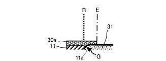
図4は、図3の領域Mの部分拡大図である。図4において、絶縁層11の貫通孔11aに充填された多孔質層31は、焼成時に収縮して絶縁層11との境界Bに段差Gが生じている。表面側蓋部30aは、境界Bを跨いで反りを抑えると共に、段差Gを埋めて表面を平坦にする。このため、段差に水が付着してセンサ素子の割れを生じたり、段差に被測定ガス中の煤や不純物が付着することを防止することができる。
なお、表面側蓋部30aは多孔質層31の全面を覆わないため、表面側蓋部30aの端縁Eは、多孔質層31の表面と段部を形成している。従って、表面側蓋部30aが形成されているか否かは、この段部の有無で判定することができる。
FIG. 4 is a partially enlarged view of region M in FIG. In FIG. 4, the
In addition, since the
次に、上記センサ素子100の製造方法の一例を簡単に説明する。まず、ジルコニア系粉末、バインダ及び有機溶剤を含むスラリーからドクターブレード法により、各固体電解質層となるグリーンシートを製造する。各固体電解質層上の電極は、電極材料、バインダ及び有機溶剤を含むペーストを上記グリーンシート上にスクリーン印刷することにより形成する。同様に、各固体電解質層の間に介装される絶縁層についても、絶縁材料(アルミナ等)、バインダ及び有機溶剤を含むペーストを上記グリーンシート(又は電極)上にスクリーン印刷することにより形成する。
そして、各固体電解質層を積層圧着し、所定温度で脱バインダ後、焼成してセンサを製造する。
なお、拡散律速部等の多孔質は、絶縁材料(アルミナ等)、バインダ及び有機溶剤を含むペーストを所定位置にスクリーン印刷した後、焼成する際にカーボン、バインダを焼失させ多数の気泡を生じさせることによって形成する。
Next, an example of a method for manufacturing the
Then, each solid electrolyte layer is laminated and pressure-bonded, debindered at a predetermined temperature, and fired to manufacture a sensor.
Note that the porous material such as the diffusion rate-determining part causes a large number of bubbles by burning out carbon and the binder when firing after a paste containing an insulating material (such as alumina), a binder and an organic solvent is screen-printed at a predetermined position. By forming.
<第2の実施形態>
図5は、本発明の第2の実施形態に係るNOxセンサが有するNOxセンサ素子101の長手方向に沿う断面図を示す。NOxセンサ素子101は、表面側蓋部300aの構成が異なることの他はNOxセンサ100素子と同様であるので、同一部分については同一符号を付して説明を省略する。
表面側蓋部300aは、絶縁層11と多孔質層31の表面(外部側)における、絶縁層11と多孔質層31の境界Bを跨ぐように設けられている。但し、表面側蓋部300aは絶縁層11の全面を覆わず、絶縁層11のうち多孔質層31の境界Bと隣接する縁部のみを覆っている。このように、表面側蓋部30aが絶縁層11と多孔質層31の境界Bを跨いでいれば、センサ素子の反りを軽減する効果を維持する。
第2の実施形態の場合、絶縁層11の全面に表面側蓋部300aを形成しなくてよいので、生産性が向上する。
<Second Embodiment>
Figure 5 shows a cross-sectional view taken along the longitudinal direction of the NO x sensor element 101 having the NO x sensor according to the second embodiment of the present invention. Since the NO x sensor element 101 is the same as the NO x sensor 100 element except that the configuration of the front
The front
In the case of the second embodiment, it is not necessary to form the surface-
<第3の実施形態>
図6は、本発明の第3の実施形態に係るNOxセンサが有するNOxセンサ素子102の長手方向に沿う断面図を示す。NOxセンサ素子102は、多孔質層31より第1対向電極20bの外形を大きくしたことに伴い、裏面側蓋部300bの構成が異なること、及び第1対向電極20bの長手方向の長さが長いことの他はNOxセンサ100素子と同様であるので、同一部分については同一符号を付して説明を省略する。
第1対向電極20bの表面に垂直な方向から投影したとき、第1対向電極20bが長いために、多孔質層31の端縁は第1対向電極2bの端縁より内側に位置している。そして、第1対向電極20bを配置することにより固体電解質層2cと絶縁層11との間に若干の隙間を生じさせるため、隙間を埋める裏面側蓋部300bを設ける。又、上記したように、第1対向電極2bの端縁が多孔質層31の端縁より外側に位置するため、単に裏面側蓋部300bを設けただけでは、第3の実施形態にように絶縁層11と多孔質層31の境界Bを跨ぐことができない。
そこで、裏面側蓋部300bを、第1対向電極20bよりも若干厚みを有するように形成し、裏面側蓋部300bから第1対向電極20bの周縁の上部を覆うように延びる片部300btを設ける。この片部300btが絶縁層11と多孔質層31の裏面において、絶縁層11と多孔質層31の境界Bを跨ぐ機能を実質的に持っている。
<Third Embodiment>
Figure 6 shows a cross-sectional view taken along the longitudinal direction of the NO x sensor element 102 having the NO x sensor according to a third embodiment of the present invention. In the NO x
When projected from the direction perpendicular to the surface of the
Therefore, the back surface
本発明は、セルの電極が外部との間で酸素を出入できるよう、センサ素子の外面側に絶縁層と多孔質層とを接して並設した、あらゆるガスセンサに適用することができる。従って、NOxセンサに限らず、自動車や各種内燃機関の排ガス中や、ボイラ等の燃焼ガス中のNOxガス濃度検出用ガスセンサや、全領域空燃比センサ等の酸素センサに本発明を適用することができる。 The present invention can be applied to any gas sensor in which an insulating layer and a porous layer are arranged in parallel with each other on the outer surface side of the sensor element so that the electrode of the cell can enter and exit oxygen from the outside. Therefore, not only the NO x sensor is applied and in an exhaust gas of an automobile or various internal combustion engine, and NO x gas concentration detection gas sensor in the combustion gases of a boiler or the like, the present invention oxygen sensor such as a full-range air-fuel ratio sensor be able to.
2b、20b 電極(第1対向電極)
2c 固体電解質層
2 セル(第1ポンプセル)
11 絶縁層
11a (絶縁層の)貫通孔
30a、300a 表面側蓋部
30b、300bt 裏面側蓋部
31 多孔質層
100〜102 センサ素子(NOxセンサ素子)
200 ガスセンサ(NOxセンサ)
B 多孔質層と絶縁層との境界
2b, 20b electrode (first counter electrode)
2c
11 insulating
200 Gas sensor (NO x sensor)
B Boundary between porous layer and insulating layer
Claims (4)
前記固体電解質層の前記表面に積層され、少なくとも前記電極の一部を取り囲むように貫通孔が設けられた絶縁層と、
前記貫通孔内に埋設されると共に、少なくとも一部が外部に露出し、前記電極と外部との間でガスが出入可能な多孔質層と、
を備えたセンサ素子を有するガスセンサであって、
前記絶縁層と前記多孔質層との表面及び裏面には、それぞれ前記貫通孔の内周面を跨ぐように設けられる表面側蓋部、及び裏面側蓋部を備えるガスセンサ。 A cell having a plate-like solid electrolyte layer and an electrode disposed on the surface of the solid electrolyte layer;
An insulating layer laminated on the surface of the solid electrolyte layer and provided with a through hole so as to surround at least a part of the electrode;
A porous layer that is embedded in the through-hole and at least part of which is exposed to the outside, and allows gas to enter and exit between the electrode and the outside,
A gas sensor having a sensor element comprising:
A gas sensor comprising a front surface side lid portion and a back surface side lid portion provided on the front and back surfaces of the insulating layer and the porous layer, respectively, so as to straddle the inner peripheral surface of the through hole.
Priority Applications (1)
| Application Number | Priority Date | Filing Date | Title |
|---|---|---|---|
| JP2008188325A JP4966266B2 (en) | 2008-07-22 | 2008-07-22 | Gas sensor |
Applications Claiming Priority (1)
| Application Number | Priority Date | Filing Date | Title |
|---|---|---|---|
| JP2008188325A JP4966266B2 (en) | 2008-07-22 | 2008-07-22 | Gas sensor |
Publications (2)
| Publication Number | Publication Date |
|---|---|
| JP2010025793A JP2010025793A (en) | 2010-02-04 |
| JP4966266B2 true JP4966266B2 (en) | 2012-07-04 |
Family
ID=41731762
Family Applications (1)
| Application Number | Title | Priority Date | Filing Date |
|---|---|---|---|
| JP2008188325A Active JP4966266B2 (en) | 2008-07-22 | 2008-07-22 | Gas sensor |
Country Status (1)
| Country | Link |
|---|---|
| JP (1) | JP4966266B2 (en) |
Cited By (3)
| Publication number | Priority date | Publication date | Assignee | Title |
|---|---|---|---|---|
| DE102015224655A1 (en) | 2014-12-10 | 2016-06-16 | Ngk Spark Plug Co., Ltd. | Gas sensor element and gas sensor |
| DE102015224419A1 (en) | 2014-12-10 | 2016-06-16 | Ngk Spark Plug Co., Ltd. | Gas sensor element and gas sensor |
| US11867659B2 (en) | 2019-04-23 | 2024-01-09 | Niterra Co., Ltd. | Sensor element and gas sensor |
Families Citing this family (6)
| Publication number | Priority date | Publication date | Assignee | Title |
|---|---|---|---|---|
| JPH0250641A (en) * | 1988-08-12 | 1990-02-20 | Nec Corp | Digital signal insertion system by direct memory access controller |
| JP5313965B2 (en) * | 2010-05-24 | 2013-10-09 | 日本特殊陶業株式会社 | NOx sensor degradation simulator |
| EP2930503B1 (en) * | 2012-12-10 | 2022-11-09 | NGK Insulators, Ltd. | Sensor element and gas sensor |
| JP6573783B2 (en) * | 2014-06-09 | 2019-09-11 | 日本碍子株式会社 | Sensor element and gas sensor |
| JP6294800B2 (en) * | 2014-09-25 | 2018-03-14 | 日本特殊陶業株式会社 | GAS SENSOR ELEMENT, GAS SENSOR AND GAS SENSOR ELEMENT MANUFACTURING METHOD |
| JP6517613B2 (en) * | 2014-10-21 | 2019-05-22 | 日本特殊陶業株式会社 | Gas sensor |
Family Cites Families (5)
| Publication number | Priority date | Publication date | Assignee | Title |
|---|---|---|---|---|
| JPH0810211B2 (en) * | 1986-09-05 | 1996-01-31 | 日本碍子株式会社 | Gas sensor and manufacturing method thereof |
| JPH0618292Y2 (en) * | 1987-12-07 | 1994-05-11 | 株式会社ユニシアジェックス | Oxygen sensor with heater |
| JP3855776B2 (en) * | 2002-01-17 | 2006-12-13 | 松下電器産業株式会社 | Oxygen pump element |
| JP3866135B2 (en) * | 2002-03-29 | 2007-01-10 | 日本特殊陶業株式会社 | Multilayer gas sensor element, method for manufacturing the same, and gas sensor |
| JP4262764B2 (en) * | 2007-12-04 | 2009-05-13 | 日本特殊陶業株式会社 | Multilayer gas sensor element |
-
2008
- 2008-07-22 JP JP2008188325A patent/JP4966266B2/en active Active
Cited By (3)
| Publication number | Priority date | Publication date | Assignee | Title |
|---|---|---|---|---|
| DE102015224655A1 (en) | 2014-12-10 | 2016-06-16 | Ngk Spark Plug Co., Ltd. | Gas sensor element and gas sensor |
| DE102015224419A1 (en) | 2014-12-10 | 2016-06-16 | Ngk Spark Plug Co., Ltd. | Gas sensor element and gas sensor |
| US11867659B2 (en) | 2019-04-23 | 2024-01-09 | Niterra Co., Ltd. | Sensor element and gas sensor |
Also Published As
| Publication number | Publication date |
|---|---|
| JP2010025793A (en) | 2010-02-04 |
Similar Documents
| Publication | Publication Date | Title |
|---|---|---|
| JP4966266B2 (en) | Gas sensor | |
| JP4911910B2 (en) | NOx measuring electrode part structure, method for forming the same, and NOx sensor element | |
| JP6059110B2 (en) | Sensor element and sensor | |
| JP4897912B2 (en) | Gas sensor | |
| US8591712B2 (en) | Gas sensor element and gas sensor | |
| US8277625B2 (en) | Gas sensing device and gas sensor | |
| JP5105488B2 (en) | Gas sensor | |
| EP2916127B1 (en) | Gas sensor | |
| US10876991B2 (en) | Gas sensor | |
| JP4865572B2 (en) | Gas sensor element, gas sensor and NOx sensor | |
| US9696274B2 (en) | Gas sensor element and gas sensor | |
| JP6684650B2 (en) | Gas sensor element and gas sensor | |
| JP6622643B2 (en) | Gas sensor element and gas sensor | |
| US20200064303A1 (en) | Gas sensor element | |
| JP6517613B2 (en) | Gas sensor | |
| US10481122B2 (en) | Gas sensor element and gas sensor | |
| US11016054B2 (en) | Gas sensor element and gas sensor including same | |
| JP4223471B2 (en) | Gas sensor element | |
| JP6438851B2 (en) | Gas sensor element and gas sensor | |
| US20250244283A1 (en) | Sensor element and gas sensor | |
| JP7114701B2 (en) | Gas sensor element and gas sensor | |
| US20240151684A1 (en) | Gas sensor element, gas sensor, and manufacturing method for gas sensor element | |
| JP2019203848A (en) | Gas sensor | |
| JP2023033155A (en) | Sensor element and gas sensor | |
| JP6392104B2 (en) | Gas sensor element and gas sensor |
Legal Events
| Date | Code | Title | Description |
|---|---|---|---|
| A621 | Written request for application examination |
Free format text: JAPANESE INTERMEDIATE CODE: A621 Effective date: 20101203 |
|
| A977 | Report on retrieval |
Free format text: JAPANESE INTERMEDIATE CODE: A971007 Effective date: 20120220 |
|
| TRDD | Decision of grant or rejection written | ||
| A01 | Written decision to grant a patent or to grant a registration (utility model) |
Free format text: JAPANESE INTERMEDIATE CODE: A01 Effective date: 20120305 |
|
| A01 | Written decision to grant a patent or to grant a registration (utility model) |
Free format text: JAPANESE INTERMEDIATE CODE: A01 |
|
| A61 | First payment of annual fees (during grant procedure) |
Free format text: JAPANESE INTERMEDIATE CODE: A61 Effective date: 20120330 |
|
| R150 | Certificate of patent or registration of utility model |
Free format text: JAPANESE INTERMEDIATE CODE: R150 Ref document number: 4966266 Country of ref document: JP Free format text: JAPANESE INTERMEDIATE CODE: R150 |
|
| FPAY | Renewal fee payment (event date is renewal date of database) |
Free format text: PAYMENT UNTIL: 20150406 Year of fee payment: 3 |
|
| R250 | Receipt of annual fees |
Free format text: JAPANESE INTERMEDIATE CODE: R250 |
|
| R250 | Receipt of annual fees |
Free format text: JAPANESE INTERMEDIATE CODE: R250 |
|
| R250 | Receipt of annual fees |
Free format text: JAPANESE INTERMEDIATE CODE: R250 |
|
| R250 | Receipt of annual fees |
Free format text: JAPANESE INTERMEDIATE CODE: R250 |
|
| R250 | Receipt of annual fees |
Free format text: JAPANESE INTERMEDIATE CODE: R250 |
|
| R250 | Receipt of annual fees |
Free format text: JAPANESE INTERMEDIATE CODE: R250 |
|
| R250 | Receipt of annual fees |
Free format text: JAPANESE INTERMEDIATE CODE: R250 |
|
| S531 | Written request for registration of change of domicile |
Free format text: JAPANESE INTERMEDIATE CODE: R313531 |
|
| R350 | Written notification of registration of transfer |
Free format text: JAPANESE INTERMEDIATE CODE: R350 |
|
| R250 | Receipt of annual fees |
Free format text: JAPANESE INTERMEDIATE CODE: R250 |
|
| R250 | Receipt of annual fees |
Free format text: JAPANESE INTERMEDIATE CODE: R250 |
|
| R250 | Receipt of annual fees |
Free format text: JAPANESE INTERMEDIATE CODE: R250 |