JP4942840B2 - Wheeled motorcycle - Google Patents
Wheeled motorcycle Download PDFInfo
- Publication number
- JP4942840B2 JP4942840B2 JP2010206211A JP2010206211A JP4942840B2 JP 4942840 B2 JP4942840 B2 JP 4942840B2 JP 2010206211 A JP2010206211 A JP 2010206211A JP 2010206211 A JP2010206211 A JP 2010206211A JP 4942840 B2 JP4942840 B2 JP 4942840B2
- Authority
- JP
- Japan
- Prior art keywords
- wheeled vehicle
- loading platform
- shaft
- pair
- hand
- Prior art date
- Legal status (The legal status is an assumption and is not a legal conclusion. Google has not performed a legal analysis and makes no representation as to the accuracy of the status listed.)
- Expired - Fee Related
Links
Images


Classifications
-
- B—PERFORMING OPERATIONS; TRANSPORTING
- B62—LAND VEHICLES FOR TRAVELLING OTHERWISE THAN ON RAILS
- B62B—HAND-PROPELLED VEHICLES, e.g. HAND CARTS OR PERAMBULATORS; SLEDGES
- B62B1/00—Hand carts having only one axis carrying one or more transport wheels; Equipment therefor
- B62B1/18—Hand carts having only one axis carrying one or more transport wheels; Equipment therefor in which the load is disposed between the wheel axis and the handles, e.g. wheelbarrows
- B62B1/24—Hand carts having only one axis carrying one or more transport wheels; Equipment therefor in which the load is disposed between the wheel axis and the handles, e.g. wheelbarrows involving tiltably-mounted containers
-
- B—PERFORMING OPERATIONS; TRANSPORTING
- B62—LAND VEHICLES FOR TRAVELLING OTHERWISE THAN ON RAILS
- B62B—HAND-PROPELLED VEHICLES, e.g. HAND CARTS OR PERAMBULATORS; SLEDGES
- B62B2301/00—Wheel arrangements; Steering; Stability; Wheel suspension
- B62B2301/10—Adjusting the position of the wheel axles to increase stability
-
- B—PERFORMING OPERATIONS; TRANSPORTING
- B62—LAND VEHICLES FOR TRAVELLING OTHERWISE THAN ON RAILS
- B62B—HAND-PROPELLED VEHICLES, e.g. HAND CARTS OR PERAMBULATORS; SLEDGES
- B62B2301/00—Wheel arrangements; Steering; Stability; Wheel suspension
- B62B2301/14—Wheel arrangements; Steering; Stability; Wheel suspension the wheel arrangement pivoting around a horizontal-longitudinal axis
Landscapes
- Engineering & Computer Science (AREA)
- Chemical & Material Sciences (AREA)
- Combustion & Propulsion (AREA)
- Transportation (AREA)
- Mechanical Engineering (AREA)
- Handcart (AREA)
Description
この発明は、手押しすることで荷物を運搬する手押し式二輪車に関するものである。 The present invention relates to a hand-held two-wheeled vehicle that carries a load by hand.
従来のこの種のものとしては、図20および図21に示すような、荷台32の下部に左右1対の支持アーム33・33を設け、左右1対の支持アーム33・33間に車輪34を軸着した一輪車31がある。この一輪車31は、狭隘な場所の走行に便利であり、広く使用されている。しかしながら、一輪車は車輪34が一輪であるため、荷台32に大きな荷物を載せて走行するときとか、走行面が平坦でないときには、荷台32のバランスが取りづらいという問題点があった。35はハンドルである。
20 and 21, as shown in FIGS. 20 and 21, a pair of left and
そこで、車輪を二輪にした手押し式二輪車が種々提案されている。
例えば、特開2007−145215号公報(特許文献1参照)・・・車輪の幅を調整
特開2006−240326号公報(特許文献2参照)・・・二輪車と一輪車とを切換
特開2002−225715号公報(特許文献3参照)・・・二輪車の車輪の傾きを調整
実用新案登録第3086239号公報(特許文献4参照)・・・二輪車と一輪車とを切換
特開平11−91573号公報(特許文献5参照)・・・前倒し可能として積み下ろしに便
等が提案されている。
Various types of hand-held two-wheeled vehicles with two wheels have been proposed.
For example, Japanese Patent Application Laid-Open No. 2007-145215 (refer to Patent Document 1)... Adjusting the wheel width Japanese Patent Application Laid-Open No. 2006-240326 (refer to Patent Document 2)... Switching between a two-wheeled vehicle and a one-wheeled vehicle Gazette (refer to Patent Document 3) ... Adjusting the inclination of the wheel of a two-wheeled vehicle Utility Model Registration No. 3086239 (refer to Patent Document 4) ... Switching between a two-wheeled vehicle and a one-wheeled vehicle JP-A-11-91573 (Patent Document) (Refer to 5) .... Fees etc. have been proposed for loading and unloading.
また、二輪車上において荷台が左右に傾いてバランスを取りやすくした手押し式二輪車も種々提案されている。
例えば、実用新案登録第3131612号公報(特許文献6参照)・・・支柱に支軸を設け、荷台と車軸の間にX状のスプリングを張設
特開2004−168246号公報(特許文献7参照)・・・台車枠と荷台フレームのV字状のパイプ間を支軸で連結
特開平11−20703号公報(特許文献8参照)・・・車輪間に弧状フレームを渡し、その上を転動輪で支持された荷台が揺動
等が提案されている。
特にこの後者の手押し式二輪車は、荷台が左右に傾いて高齢者でも非常にバランスを取りやすくなっている。
Various types of hand-held two-wheeled vehicles have also been proposed in which the loading platform is inclined to the left and right on the two-wheeled vehicle to facilitate balance.
For example, Utility Model Registration No. 3131612 (see Patent Document 6) ... A support shaft is provided on a support column, and an X-shaped spring is stretched between a cargo bed and an axle. Japanese Patent Application Laid-Open No. 2004-168246 (see Patent Document 7) ) ... Connected between the V-shaped pipes of the carriage frame and the loading frame with a support shaft. Japanese Patent Application Laid-Open No. 11-20703 (refer to Patent Document 8) .... It has been proposed that the loading platform supported by the oscillates.
In particular, this latter hand-held two-wheeled vehicle is very easy to balance even for elderly people because the loading platform tilts to the left and right.
前記従来の二輪車上において荷台が左右に傾いてバランスを取りやすくした手押し式二輪車は、それぞれ支柱に支軸を設け、荷台と車軸の間にX状のスプリングを張設したり、台車枠と荷台フレームのV字状のパイプ間を支軸で連結したり、車輪間に弧状フレームを渡し、その上を転動輪で支持された荷台が揺動するようにしたものである。 In the conventional two-wheeled vehicle, the load-type two-wheeled vehicle in which the loading platform tilts to the left and right for easy balancing is provided with a support shaft on each column, and an X-shaped spring is stretched between the loading platform and the axle, or the carriage frame and the loading platform The V-shaped pipes of the frame are connected by a support shaft, or an arc-shaped frame is passed between wheels so that a bed supported by a rolling wheel swings on the frame.
しかしながら、前記従来の二輪車上において荷台が左右に傾いてバランスを取りやすくした手押し式二輪車においては、いずれも二輪車上において荷台を左右に傾ける機構に特徴があった。
したがって、従来の一輪車を簡便に二輪車に改造したり、二輪車と一輪車とを簡単に切換えることができる構造にはなっていなかった。
However, in the conventional hand-held two-wheeled vehicle in which the loading platform tilts to the left and right on the above-described two-wheeled vehicle so that it is easy to balance, there is a feature in the mechanism that tilts the loading platform to the left and right on the two-wheeled vehicle.
Therefore, the conventional unicycle cannot be easily modified into a two-wheeled vehicle, or the structure can be easily switched between the two-wheeled vehicle and the one-wheeled vehicle.
この発明の目的は、従来の一輪車を簡便に二輪車に改造したり、二輪車と一輪車とを簡単に切換えることができる手押し式二輪車を提供することにある。 An object of the present invention is to provide a hand-held two-wheeled vehicle that can be easily modified from a conventional one-wheeled vehicle to a two-wheeled vehicle or can easily switch between a two-wheeled vehicle and a one-wheeled vehicle.
上記の目的を達成するために、この発明の手押し式二輪車は、
荷台の前方下部に、該荷台の移動方向に直交する向きで支持体に支持された車軸に、2つの車輪が左右に離されて支持されている手押し式二輪車であって、
前記車輪は前記車軸に回転自在に支持され、
前記支持体は前記車軸の車輪の中間位置に固着した軸受部と、前記荷台から垂設した左右1対の支持アームと、この左右1対の支持アームの端部の間に差し渡された連結軸と、この連結軸に下向きに取り付けた第1の連結片と前記軸受部に上向きに取り付けた第2の連結片とを回動可能に軸着する支軸とを有し、
前記荷台の支持アームが支軸を中心として所定の角度まで傾くことを可能としたことを特徴とするものである。
In order to achieve the above object, the hand-held two-wheeled vehicle of the present invention is
A push-type two-wheeled vehicle in which two wheels are supported on an axle supported by a support body in a direction orthogonal to a moving direction of the cargo bed at a lower front portion of the cargo bed,
The wheels are rotatably supported on the axle;
The support body includes a bearing portion fixed to an intermediate position of the wheel of the axle, a pair of left and right support arms suspended from the loading platform, and a connection spanned between ends of the pair of left and right support arms. A shaft, and a support shaft that pivotally attaches a first connection piece attached downward to the connection shaft and a second connection piece attached upward to the bearing portion;
The support arm of the loading platform can be tilted to a predetermined angle around the support shaft.
この発明の手押し式二輪車は、前記支持体の左右1対の支持アームの端部の間に差し渡された連結軸が、前記左右1対の支持アームの端部にそれぞれ垂設したブラケットに、所定長さの連結板の一端をそれぞれボルトナットで固定し、該連結板の他端に前記連結軸を差し渡して固定したことをも特徴とするものである。 In the hand-held two-wheeled vehicle according to the present invention, the connecting shafts inserted between the ends of the pair of left and right support arms of the support body are respectively attached to the brackets suspended from the ends of the pair of left and right support arms. One end of the connecting plate having a predetermined length is fixed with a bolt and nut, and the connecting shaft is inserted and fixed to the other end of the connecting plate.
この発明の手押し式二輪車は、前記荷台の支持アームが、その先端に荷台の前端から垂下させた補強アームの端部を連結して補強されていることをも特徴とするものである。 The hand-held two-wheeled vehicle according to the present invention is characterized in that the support arm of the cargo bed is reinforced by connecting an end portion of a reinforcement arm suspended from the front end of the cargo bed to the tip thereof.
請求項1に記載の手押し式二輪車では、前記支持体は前記車軸の車輪の中間位置に固着した軸受部と、前記荷台から垂設した左右1対の支持アームと、この左右1対の支持アームの端部の間に差し渡された連結軸と、この連結軸に下向きに取り付けた第1の連結片と前記軸受部に上向きに取り付けた第2の連結片とを回動可能に軸着する支軸とを有し、前記荷台の支持アームが支軸を中心として所定の角度まで傾くことを可能としたものである。
このため従来の一輪車を分解して簡便に二輪車に改造したり、二輪車と一輪車とを簡単に切換えることが可能な手押し式二輪車を提供することができる。
2. The hand-held two-wheeled vehicle according to claim 1, wherein the support is a bearing portion fixed to an intermediate position of the wheel of the axle, a pair of left and right support arms suspended from the cargo bed, and the pair of left and right support arms. A connecting shaft passed between the end portions of the first connecting piece, a first connecting piece attached downward to the connecting shaft, and a second connecting piece attached upward to the bearing portion so as to be pivotable. The support arm of the loading platform can be tilted to a predetermined angle with the support shaft as a center.
Therefore, it is possible to provide a hand-held two-wheeled vehicle that can be disassembled from a conventional one-wheeled vehicle and easily remodeled into a two-wheeled vehicle or can be easily switched between the two-wheeled vehicle and the one-wheeled vehicle.
請求項2に記載の手押し式二輪車では、前記支持体の左右1対の支持アームの端部の間に差し渡された連結軸が、前記左右1対の支持アームの端部にそれぞれ垂設したブラケットに、所定長さの連結板の一端をそれぞれボルトナットで固定し、該連結板の他端に前記連結軸を差し渡して固定したものである。
このため前記荷台の支持アームの構造に応じて前記連結軸を、従来のブラケットにそのまま取り付けたり、前記ブラケットには連結板の一端をそれぞれボルトナットで固定し、該連結板の他端に前記連結軸を差し渡して固定することにより、取付位置を後方に移動させることができる。
したがって、前記荷台の支持アームの構造に応じて車輪の取付位置を適宜変更することが可能な手押し式二輪車を提供することができる。
In the hand-held two-wheeled vehicle according to claim 2, a connecting shaft that is interposed between the ends of the pair of left and right support arms of the support body is respectively suspended from the ends of the pair of left and right support arms. One end of a connecting plate of a predetermined length is fixed to the bracket with a bolt and nut, and the connecting shaft is inserted and fixed to the other end of the connecting plate.
Therefore, according to the structure of the support arm of the loading platform, the connecting shaft is attached to a conventional bracket as it is, or one end of a connecting plate is fixed to the bracket with a bolt and nut, and the connecting end is connected to the other end of the connecting plate. By attaching and fixing the shaft, the attachment position can be moved backward.
Therefore, it is possible to provide a hand-held two-wheeled vehicle capable of appropriately changing the mounting position of the wheel according to the structure of the support arm of the cargo bed.
請求項3に記載の手押し式二輪車では、請求項1に記載の前記荷台の支持アームを、その先端に荷台の前端から垂下させた補強アームの端部を連結して補強したので、荷台が左右に傾いた場合でも荷台の変形を防止し、大きな負荷に耐えることができる手押し式二輪車を提供することが可能となった。 In the hand-held two-wheeled vehicle according to claim 3, since the support arm of the load carrier according to claim 1 is reinforced by connecting the end of the reinforcement arm that is suspended from the front end of the load carrier to the tip thereof, This makes it possible to provide a hand-held two-wheeled vehicle that can prevent a load carrier from being deformed even when it is tilted toward the vehicle and can withstand a large load.
以下、この発明に係る手押し式二輪車の実施形態を図面に基いて詳細に説明する。
図1ないし図6はこの発明に係る手押し式二輪車の第1実施例を示すもので、図1はこの実施例の手押し式二輪車の正面図、図2はその側面図、図3はその縦断面図、図4および図5はそれぞれ荷台を傾けた状態を示す正面図、図6は片方の車輪が段差に乗り上げた状態の正面図である。
Embodiments of a hand-held two-wheeled vehicle according to the present invention will be described below in detail with reference to the drawings.
1 to 6 show a first embodiment of a hand-held two-wheeled vehicle according to the present invention. FIG. 1 is a front view of the hand-held two-wheeled vehicle of this embodiment, FIG. 2 is a side view thereof, and FIG. 4, FIG. 4 and FIG. 5 are front views showing a state in which the loading platform is tilted, and FIG. 6 is a front view showing a state where one wheel rides on a step.
図1ないし図3において手押し式二輪車11は、荷台12の前方下部に、該荷台12の移動方向に直交する向きで支持体13に支持された車軸16に、2つの車輪14,15が左右に離されて取り付けられ、前記車輪14,15は前記車軸16に回転自在に支持され、手押し用のハンドル17の操作により自在に進退させることができる。
In FIG. 1 to FIG. 3, the hand-held two-wheeled
前記支持体13は前記車軸16の左右の車輪14,15の中間位置に固着した軸受部21と、前記荷台12から垂設した左右1対の支持アーム22,23と、この左右1対の支持アーム22,23の端部の間に差し渡された連結軸24とを有している。
そして、この連結軸24に下向きに取り付けた第1の連結片25と前記軸受部21に上向きに取り付けた第2の連結片26とを支軸27で回動可能に軸着することにより、前記荷台12の支持アーム22,23が、支軸27を中心として所定の角度まで傾くことを可能としたのである。
The
Then, the
すなわち、荷台12は図4および図5のように車輪14,15上で自在に傾けることができるので、安定した走行を確保しつつ、荷台12から荷物を下ろす際には傾けて無理なく荷物を持ち上げることができる。
また、図6のようにどちらかの車輪14ないし15が段差28に乗り上げてもその傾きを難なく吸収することができるので、畑や農道等の凹凸のある場所でも、荷台12を水平に保ったまま安定して走行させることが可能となるのである。
That is, since the
Further, as shown in FIG. 6, even if one of the
なお、前記荷台12から垂設した左右1対の支持アーム22,23には、その先端に荷台12の前端から垂下させた補強アーム29,30の端部を連結してあるので、荷台12を傾けても補強アーム29,30で補強されているため、荷台12が変形することもなく、かつより大きな負荷に耐えることができることとなる。
前記荷台12から垂設した左右1対の支持アーム22,23は、その下端部分において前方へ水平方向に折り曲げられており、この水平位置において車輪14,15が取り付けてあるので、前記荷台12の支持アーム22,23をより深く傾けることができるようになっている。
The pair of left and
The pair of left and
この発明の手押し式二輪車11の製作に際しては、従来の一輪車の荷台12から垂設した左右1対の支持アーム22,23間から車輪を外し、支持アーム22,23間に第1の連結片25を予め設けた連結軸24を取り付ける。
また、前記1対の車輪14,15を車軸16の左右に回動可能に軸着し、前記車軸16上の軸受部21には予め第2の連結片26を取り付けておく。
When the hand-held two-wheeled
Further, the pair of
そして、前記連結軸24に下向きに取り付けた第1の連結片25と前記軸受部21に上向きに取り付けた第2の連結片26とを支軸27で回動可能に軸着すれば、前記荷台12の支持アーム22,23が、支軸27を中心として所定の角度まで傾けることができる手押し式二輪車11が完成するのである。
Then, if the first connecting
もちろん、手押し式二輪車11を一輪車に変更するには、上記作業と逆の順序で分解組立を行なえばよい。
Of course, in order to change the hand-held two-wheeled
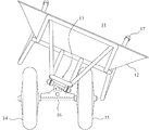
図7ないし図12はこの発明に係る手押し式二輪車の第2実施例を示すもので、図7はこの実施例の手押し式二輪車の正面図、図8はその側面図、図9はその縦断面図、図10および図11はそれぞれ荷台を傾けた状態を示す正面図、図12は片方の車輪が段差に乗り上げた状態の正面図である。 7 to 12 show a second embodiment of the hand-held two-wheeled vehicle according to the present invention. FIG. 7 is a front view of the hand-held two-wheeled vehicle of this embodiment, FIG. 8 is a side view thereof, and FIG. 10, FIG. 10 and FIG. 11 are front views showing a state in which the loading platform is inclined, and FIG. 12 is a front view showing a state where one wheel rides on a step.
図7ないし図9において手押し式二輪車31は、荷台32の前方下部に、該荷台32の移動方向に直交する向きで支持体33に支持された車軸36に、2つの車輪34,35が左右に離されて取り付けられ、前記車輪34,35は前記車軸36に回転自在に支持され、手押し用のハンドル37の操作により自在に進退させることができる。
7 to 9, a hand-held two-wheeled
前記支持体33は前記車軸36の左右の車輪34,35の中間位置に固着した軸受部41と、前記荷台32から垂設した左右1対の支持アーム42,43と、この左右1対の支持アーム42,43の端部の間に差し渡された連結軸44とを有している。
この第2実施例の手押し式二輪車においては、前記支持体33の左右1対の支持アーム42,43の端部の間に差し渡された前記連結軸44が、前記左右1対の支持アーム42,43の端部にそれぞれ垂設したブラケット51,52にその取付位置を適宜変更して取り付けることができる。
The
In the hand-held two-wheeled vehicle according to the second embodiment, the connecting
例えば、前記ブラケット51,52に所定長さの連結板53の一端をそれぞれボルトナット54,55で固定し、さらに該連結板53の他端に前記連結軸44を差し渡して固定すれば、前記連結軸44の取付位置を後方にずらすことができる。
より詳しくは、前記荷台32から垂設した左右1対の支持アーム42,43に対し、荷台32の前端から垂下させた補強アーム49,50の端部を連結しているが、該連結位置が前記支持アーム42,43の先端であったり、やや後方にずれたりしているので、そのような多種の構造に柔軟に対応できるようになるのである。
For example, if one end of a connecting
More specifically, the ends of the reinforcing
したがって、まず前記荷台32の支持アーム42,43の構造に応じて前記連結軸44を、従来のブラケット51,52にそのまま取り付けることができる。また、前記ブラケット51,52に連結板53の一端をそれぞれボルトナット54,55で固定し、該連結板53の他端に前記連結軸44を差し渡して固定することにより、取付位置を後方に移動させることも可能である。
したがって、前記荷台32の支持アーム42,43の構造に応じて車輪34,35の取付位置を適宜変更することが可能な手押し式二輪車を提供することができる。
Therefore, first, the connecting
Accordingly, it is possible to provide a hand-held two-wheeled vehicle capable of appropriately changing the mounting positions of the
その上で、この連結軸44に下向きに取り付けた第1の連結片45と前記軸受部41に上向きに取り付けた第2の連結片46とを支軸47で回動可能に軸着することにより、前記荷台32の支持アーム42,43が、支軸47を中心として所定の角度まで傾くことを可能としたのである。
Then, the first connecting
すなわち、荷台32は図10および図11のように車輪34,35上で自在に傾けることができるので、安定した走行を確保しつつ、荷台32から荷物を下ろす際には傾けて無理なく荷物を持ち上げることができる。
また、図12のようにどちらかの車輪34ないし35が段差48に乗り上げてもその傾きを難なく吸収することができるので、畑や農道等の凹凸のある場所でも、荷台32を水平に保ったまま安定して走行させることが可能となるのである。
That is, since the
Also, as shown in FIG. 12, even if one of the
なお記荷台32から垂設した左右1対の支持アーム42,43には、その先端に荷台32の前端から垂下させた補強アーム49,50の端部を連結してあるので、荷台32を傾けても補強アーム49,50で補強されているため、荷台32が変形することもなく、かつより大きな負荷に耐えることができることとなる。
前記荷台32から垂設した左右1対の支持アーム42,43は、その下端部分において前方へ水平方向に折り曲げられており、この水平位置において車輪34,35が取り付けてあるので、前記荷台32の支持アーム42,43をより深く傾けることができるようになっている。
The pair of left and
The pair of left and
この第2実施例の手押し式二輪車31の製作に際しては、従来の一輪車の荷台32から垂設した左右1対の支持アーム42,43間から車輪を外し、支持アーム42,43間に第1の連結片45を予め設けた連結軸44を取り付ける。
すなわち、前記左右1対の支持アーム42,43の端部にそれぞれ垂設した前記ブラケット51,52に、所定長さの連結板53の一端をそれぞれボルトナット54,55で固定し、さらに該連結板53の他端には前記連結軸44を差し渡して固定する。
また、前記1対の車輪34,35を車軸36の左右に回動可能に軸着し、前記車軸36上の軸受部41には予め第2の連結片46を取り付けておく。
In manufacturing the hand-held two-wheeled
That is, one end of a connecting
Further, the pair of
図13ないし図19に、前記支持体33への前記連結軸44の組み付け方法を詳しく説明する。
図13において、予め第2の連結片46を取り付けた前記車軸36上の軸受部41には、着脱可能に支軸47が取り付けてある。他方、前記ブラケット51,52に取り付けられる所定長さの連結板53の一端にはそれぞれボルトナット54,55が取り付けられ、さらに該連結板53の他端には、第1の連結片45を予め設けた前記連結軸44が差し渡して取り付けられている。
A method for assembling the connecting
In FIG. 13, a
その後、前記連結軸44上の第2の連結片46に、前記連結軸44に垂設した第1の連結片45をはめ込み、図14に示すように両者を支軸47で連結固定する。
また図15および図16においては、前記左右1対の支持アーム42,43の端部にそれぞれ垂設した前記ブラケット51,52に、所定長さの連結板53の一端がそれぞれボルトナット54,55を介して取り付けられ、さらに該連結板53の他端には、前記連結軸44が差し渡して取り付けられている。
Thereafter, the first connecting
15 and 16, one end of a connecting
そして、前記連結軸44に下向きに取り付けた第1の連結片45と前記軸受部41に上向きに取り付けた第2の連結片46とを、図17の組み付け前の状態から図18のように組み付け、図19のように支軸47で回動可能に軸着する。
そうすれば、前記荷台32の支持アーム42,43が、支軸47を中心として所定の角度まで傾けることができる手押し式二輪車31が完成するのである。
Then, the first connecting
Then, the hand-held two-wheeled
もちろん、手押し式二輪車31を一輪車に変更するには、上記作業と逆の順序で分解組立を行なえばよい。
Of course, in order to change the hand-held two-wheeled
以上、この発明を例えば農作業等に適した手押し式二輪車として説明してきたが、それ以外の用途に用いられる手押し式二輪車であっても、同様に適用できることはいうまでもない。 As described above, the present invention has been described as a hand-held two-wheeled vehicle suitable for, for example, farm work, but it goes without saying that the present invention can be similarly applied to a hand-held two-wheeled vehicle used for other purposes.
11 手押し式二輪車
12 荷台
13 支持体
14,15 車輪
16 車軸
17 ハンドル
21 軸受部
22,23 支持アーム
24 連結軸
25 第1の連結片
26 第2の連結片
27 支軸
28 段差
29,30 補強アーム
31 手押し式二輪車
32 荷台
33 支持体
34,35 車輪
36 車軸
37 ハンドル
41 軸受部
42,43 支持アーム
44 連結軸
45 第1の連結片
46 第2の連結片
47 支軸
48 段差
49,50 補強アーム
51,52 ブラケット
53 連結板
54,55 ボルトナット
DESCRIPTION OF
Claims (3)
前記車輪は前記車軸に回転自在に支持され、
前記支持体は前記車軸の車輪の中間位置に固着した軸受部と、前記荷台から垂設した左右1対の支持アームと、この左右1対の支持アームの端部の間に差し渡された連結軸と、この連結軸に下向きに取り付けた第1の連結片と前記軸受部に上向きに取り付けた第2の連結片とを回動可能に軸着する支軸とを有し、
前記荷台の支持アームが支軸を中心として所定の角度まで傾くことを可能としたことを特徴とする手押し式二輪車。 A push-type two-wheeled vehicle in which two wheels are supported on an axle supported by a support body in a direction orthogonal to a moving direction of the cargo bed at a lower front portion of the cargo bed,
The wheels are rotatably supported on the axle;
The support body includes a bearing portion fixed to an intermediate position of the wheel of the axle, a pair of left and right support arms suspended from the loading platform, and a connection spanned between ends of the pair of left and right support arms. A shaft, and a support shaft that pivotally attaches a first connection piece attached downward to the connection shaft and a second connection piece attached upward to the bearing portion;
A hand-held two-wheeled vehicle characterized in that the support arm of the cargo bed can be tilted to a predetermined angle about a support shaft.
Priority Applications (2)
| Application Number | Priority Date | Filing Date | Title |
|---|---|---|---|
| JP2010206211A JP4942840B2 (en) | 2009-12-14 | 2010-09-15 | Wheeled motorcycle |
| PCT/JP2010/072023 WO2011074458A1 (en) | 2009-12-14 | 2010-12-08 | Two-wheeled wheelbarrow |
Applications Claiming Priority (3)
| Application Number | Priority Date | Filing Date | Title |
|---|---|---|---|
| JP2009282342 | 2009-12-14 | ||
| JP2009282342 | 2009-12-14 | ||
| JP2010206211A JP4942840B2 (en) | 2009-12-14 | 2010-09-15 | Wheeled motorcycle |
Publications (2)
| Publication Number | Publication Date |
|---|---|
| JP2011143914A JP2011143914A (en) | 2011-07-28 |
| JP4942840B2 true JP4942840B2 (en) | 2012-05-30 |
Family
ID=44167215
Family Applications (1)
| Application Number | Title | Priority Date | Filing Date |
|---|---|---|---|
| JP2010206211A Expired - Fee Related JP4942840B2 (en) | 2009-12-14 | 2010-09-15 | Wheeled motorcycle |
Country Status (2)
| Country | Link |
|---|---|
| JP (1) | JP4942840B2 (en) |
| WO (1) | WO2011074458A1 (en) |
Cited By (1)
| Publication number | Priority date | Publication date | Assignee | Title |
|---|---|---|---|---|
| US8609174B2 (en) | 2006-11-17 | 2013-12-17 | Barry Callebaut Ag | Method for producing a soluble cocoa product from cocoa powder |
Families Citing this family (4)
| Publication number | Priority date | Publication date | Assignee | Title |
|---|---|---|---|---|
| EP2711263B1 (en) * | 2011-05-18 | 2016-08-10 | Zhejiang Hengfeng Top Leisure Co., Ltd. | Balanced luggage van |
| SE539101C2 (en) * | 2015-08-12 | 2017-04-11 | Rindus Ind Ab | Roll container |
| USD811681S1 (en) | 2016-04-12 | 2018-02-27 | Bearzall, Llc | Wheelbarrow |
| FR3051425B1 (en) * | 2016-05-20 | 2018-05-18 | Defay Tp | LATERAL SHROLLER AND METHOD FOR IMPLEMENTING SAME |
Family Cites Families (10)
| Publication number | Priority date | Publication date | Assignee | Title |
|---|---|---|---|---|
| JPS5336270U (en) * | 1976-09-03 | 1978-03-30 | ||
| JPS5912154B2 (en) * | 1976-09-14 | 1984-03-21 | シチズン時計株式会社 | digital display electronic clock |
| JPS59190666A (en) * | 1983-04-12 | 1984-10-29 | Mutsuji Kamimura | Revolution indicator utilizing super-conductive quantum interferometer |
| JPS59190666U (en) * | 1983-06-04 | 1984-12-18 | 椎名 正二 | Transport vehicle with fixed reinforcement plate |
| JPH082883B2 (en) * | 1986-06-06 | 1996-01-17 | クミアイ化学工業株式会社 | 2-Phenoxypyrimidine derivative and herbicide |
| JPS63115870U (en) * | 1987-01-23 | 1988-07-26 | ||
| JPH0858596A (en) * | 1994-08-18 | 1996-03-05 | Mamoru Norioka | Trolley |
| JP2004168246A (en) * | 2002-11-22 | 2004-06-17 | Takeji Watanabe | Hand-pushing type two-wheel barrow |
| JP4310555B2 (en) * | 2005-06-23 | 2009-08-12 | 俊彦 辻村 | Handcart |
| JP3131612U (en) * | 2007-02-26 | 2007-05-17 | 飯塚 和睦 | Two-wheeled vehicle with hand-held handle |
-
2010
- 2010-09-15 JP JP2010206211A patent/JP4942840B2/en not_active Expired - Fee Related
- 2010-12-08 WO PCT/JP2010/072023 patent/WO2011074458A1/en active Application Filing
Cited By (1)
| Publication number | Priority date | Publication date | Assignee | Title |
|---|---|---|---|---|
| US8609174B2 (en) | 2006-11-17 | 2013-12-17 | Barry Callebaut Ag | Method for producing a soluble cocoa product from cocoa powder |
Also Published As
| Publication number | Publication date |
|---|---|
| WO2011074458A1 (en) | 2011-06-23 |
| JP2011143914A (en) | 2011-07-28 |
Similar Documents
| Publication | Publication Date | Title |
|---|---|---|
| JP5011293B2 (en) | Self-powered vehicle with selectable operating modes | |
| US9114844B2 (en) | Bicycle conversion kit and tricycle apparatus | |
| CN1124952C (en) | Steerable load-carrying assemblies | |
| JP4942840B2 (en) | Wheeled motorcycle | |
| US20210024164A1 (en) | Two-tiered structural frame for a three-wheeled cargo bike | |
| US20070261905A1 (en) | Electrically operated three-wheeled pushcart | |
| JP3208136U (en) | Pusher structure that can be combined with a bicycle | |
| US9469323B2 (en) | Cart capable of being combined to a bicycle | |
| JP4116096B2 (en) | Suspension structure for transport equipment equipped with wheels | |
| KR20150042434A (en) | Motor-driven Cart | |
| JP4297384B1 (en) | Driving stability motorcycle | |
| KR101377046B1 (en) | Cart powered by electricity | |
| JP4781225B2 (en) | Casters and articles with casters | |
| JP5829979B2 (en) | Tricycle | |
| JP2005193740A (en) | Multi-use tricycle | |
| JP5314176B1 (en) | Tricycle | |
| US20080067768A1 (en) | Steering structure of a walk-substituting cart | |
| JP2002059843A (en) | Vehicle provided with swivel casters | |
| JP2018090106A (en) | Auxiliary wheel and cart having auxiliary wheel | |
| JPH08169345A (en) | Vehicle | |
| CN203612025U (en) | Cart structure capable of being combined with bicycle | |
| JP2005088606A (en) | Folding bicycle | |
| JP7389706B2 (en) | hand truck | |
| JP3087039U (en) | Bicycle front carrier | |
| JPH08207774A (en) | Dolly |
Legal Events
| Date | Code | Title | Description |
|---|---|---|---|
| A621 | Written request for application examination |
Free format text: JAPANESE INTERMEDIATE CODE: A621 Effective date: 20111213 |
|
| A871 | Explanation of circumstances concerning accelerated examination |
Free format text: JAPANESE INTERMEDIATE CODE: A871 Effective date: 20111213 |
|
| A871 | Explanation of circumstances concerning accelerated examination |
Free format text: JAPANESE INTERMEDIATE CODE: A871 Effective date: 20111226 |
|
| A975 | Report on accelerated examination |
Free format text: JAPANESE INTERMEDIATE CODE: A971005 Effective date: 20120117 |
|
| A521 | Written amendment |
Free format text: JAPANESE INTERMEDIATE CODE: A523 Effective date: 20120120 |
|
| A131 | Notification of reasons for refusal |
Free format text: JAPANESE INTERMEDIATE CODE: A131 Effective date: 20120120 |
|
| TRDD | Decision of grant or rejection written | ||
| A01 | Written decision to grant a patent or to grant a registration (utility model) |
Free format text: JAPANESE INTERMEDIATE CODE: A01 Effective date: 20120223 |
|
| A01 | Written decision to grant a patent or to grant a registration (utility model) |
Free format text: JAPANESE INTERMEDIATE CODE: A01 |
|
| A61 | First payment of annual fees (during grant procedure) |
Free format text: JAPANESE INTERMEDIATE CODE: A61 Effective date: 20120228 |
|
| R150 | Certificate of patent or registration of utility model |
Free format text: JAPANESE INTERMEDIATE CODE: R150 |
|
| FPAY | Renewal fee payment (event date is renewal date of database) |
Free format text: PAYMENT UNTIL: 20150309 Year of fee payment: 3 |
|
| R250 | Receipt of annual fees |
Free format text: JAPANESE INTERMEDIATE CODE: R250 |
|
| LAPS | Cancellation because of no payment of annual fees |