JP4891649B2 - Multipack packaging box - Google Patents
Multipack packaging box Download PDFInfo
- Publication number
- JP4891649B2 JP4891649B2 JP2006131020A JP2006131020A JP4891649B2 JP 4891649 B2 JP4891649 B2 JP 4891649B2 JP 2006131020 A JP2006131020 A JP 2006131020A JP 2006131020 A JP2006131020 A JP 2006131020A JP 4891649 B2 JP4891649 B2 JP 4891649B2
- Authority
- JP
- Japan
- Prior art keywords
- tear
- opening
- packaging box
- container
- piece
- Prior art date
- Legal status (The legal status is an assumption and is not a legal conclusion. Google has not performed a legal analysis and makes no representation as to the accuracy of the status listed.)
- Expired - Fee Related
Links
Images


Landscapes
- Packages (AREA)
Description
本発明は、例えば缶ビール、発泡酒缶、チューハイ缶等のアルコール飲料缶や、缶ジュース、缶コーヒー、缶紅茶、缶入り茶等ノンアルコール飲料缶等の一定数量の容器を並列した状態のまま包装するマルチパック用包装箱に関する。なお、本発明でいう「容器」とは、内容物が充填されている製品の形態のものをいう。 In the present invention, for example, alcohol beverage cans such as canned beer, sparkling liquor cans, Chu-hi cans, and non-alcoholic beverage cans such as can juice, canned coffee, canned tea, canned tea, etc. The present invention relates to a multipack packaging box. In addition, the “container” in the present invention refers to a product in a form filled with contents.
従来から、缶ビールや缶ジュース等の複数個の容器を複数個一列あるいは複数列で起立させた状態のまま整列させて置き、つぎに容器の上部、側部および下部を包み込むようにして包装した紙製のマルチパック用包装箱が使用されている。 Conventionally, a plurality of containers such as canned beer and canned juice are arranged in a standing state in a row or a plurality of rows, and then packaged so as to wrap the upper, side and lower portions of the container. Paper multipack packaging boxes are used.
このようなマルチパック用包装箱の使用により、複数個の缶ビールや缶ジュース等を1個の包装体にまとめて一度にかつ簡易に持ち運ぶことができるようになり、さらに、纏め売りの効果も相俟って当該マルチパック用包装箱の使用が近年急速に拡大しつつある。 By using such a multi-pack packaging box, it becomes possible to carry a plurality of canned beers, canned juices, etc. in a single package and carry them easily at one time. Together, the use of such multipack packaging boxes has been rapidly expanding in recent years.
小売店では、一般に、マルチパック用包装箱は段状の陳列棚やショーケースに収納された状態で販売されており、また、家庭で飲食する消費者は、一般にマルチパック用包装箱を段状の収納棚に収納していることが多い。特に、マルチパックのまま冷蔵庫などに保管することにより、容器がバラバラに散乱することなく1箇所にコンパクトな状態で保管することができる。 In retail stores, multipack packaging boxes are generally sold in a state of being stored in stepped shelves or showcases. Consumers who eat and drink at home generally use multipack packaging boxes in a stepped form. Often stored in a storage shelf. In particular, by storing the multipack in a refrigerator or the like, the container can be stored in a compact state in one place without being scattered apart.
しかしながら、このようなマルチパック用包装箱は、収納スペース等の制約により、容器を立てた状態でのいわゆる縦置きでは収納することができず、容器を寝かせたいわゆる横置きの状態でなければ収納できない場合がある。 However, such a multipack packaging box cannot be stored in a so-called vertical position with the container standing up due to restrictions on the storage space, etc., and is stored only in a so-called horizontal position in which the container is laid down. There are cases where it is not possible.
横置きの状態での保管は、容器が取り出しにくく、また、容器を取り出す際に、容器の収納形態がくずれて他の容器が転がり落ちるおそれがあるという問題が生じていた。特に、容器が後方へ転がり落ちた場合には、奥まった後方の狭い場所に手を伸ばして転がった容器を取り出さなければならないという余分な負担を消費者に強いることになる。 Storage in the horizontal state has caused problems that it is difficult to take out the container, and that when the container is taken out, the storage form of the container may be damaged and other containers may roll off. In particular, when the container rolls backward, the consumer is forced to take an extra burden of having to reach out to the narrow space behind the back and take out the rolled container.
このような課題を解決するために本願発明は創案されたものであって、その目的は、マルチパック用包装箱を横置きの状態での保管した場合でも、容器の取り出しを容易とすることができ、かつ、取り出し時に容器が後ろへ転がりにくくすることができるマルチパック用包装箱を提供することにある。 The present invention has been devised to solve such problems, and its purpose is to facilitate the removal of the container even when the multipack packaging box is stored in a horizontal state. Another object of the present invention is to provide a multipack packaging box that can be made difficult to roll backward when taken out.
上記課題を解決するために本発明のマルチパック用包装箱は、複数個を並列に配置された容器群の上面を覆う上面板と、この上面板の両側部に連接され並列された各容器の側面を覆うように配置された対向する側面板と、これら側面板に連接され互いに係着しうる係止部を有する底面板とを備え、前記底面板を係着することにより前記容器群を包むように収納することができるとともに、側面板が存在しない両端部において容器群の一部の側面が覗く第1の開口部および第2の開口部が形成されるマルチパック用包装箱において、前記側面板には、側面板の所定の奥側位置から手前位置である第1の開口部に向けて、引き裂き除去可能な引裂き開口片が少なくとも1つ形成されており、前記側面板に形成された引裂き開口片は、引き裂き除去される形状に沿って不連続な切り込み線が形成されており、引き裂き除去の際の切り込み線の最終端が、第1の開口部の近傍に形成されている折り込み片の折り線の両端に実質的に向けられて形成されており、前記底面板の前記第2の開口部に近い位置には、箱の内側に凸状に突出した容器の転がり防止用ストッパが形成されているように構成される。
In order to solve the above-described problems, a multipack packaging box of the present invention includes a top plate covering the top surface of a plurality of containers arranged in parallel, and each container connected in parallel to both sides of the top plate. An opposing side plate disposed so as to cover the side surface, and a bottom plate having a locking portion that is connected to the side plates and can be engaged with each other, and the container group is enclosed by engaging the bottom plate. In the multipack packaging box in which the first opening and the second opening that can be seen through a part of the side surface of the container group are formed at both end portions where the side plate does not exist. In this case, at least one tear opening piece that can be removed by tearing is formed from a predetermined back side position of the side plate toward the front opening, and the tear opening formed in the side plate. Piece tearing removal A discontinuous cut line is formed along the shape to be cut, and the final end of the cut line at the time of tear removal is substantially at both ends of the fold line of the folded piece formed in the vicinity of the first opening. And a stopper for preventing rolling of the container projecting inwardly from the box is formed at a position near the second opening of the bottom plate. .
また、本発明のマルチパック用包装箱の好ましい態様として、前記容器の転がり防止用ストッパは、前記引き裂き除去可能な引裂き開口片を引き裂き除去する方向とは反対方向に位置する最後部の2つの容器の底部周縁と係合するように、2つの容器の間に凸状に突出して形成される。 Further, as a preferred embodiment of the multipack packaging box of the present invention, the stopper for preventing rolling of the container is the last two containers positioned in the direction opposite to the direction of tearing and removing the tear opening piece that can be removed by tearing. It is formed to protrude in a convex shape between the two containers so as to engage with the bottom periphery of the container.
また、本発明のマルチパック用包装箱の好ましい態様として、前記容器の転がり防止用ストッパは、前記底面板に形成された折り曲げ片と、形態固定用のフック片と、の組み立てにより形成され、前記折り曲げ片は、コの字状に打ち抜かれた打ち抜き平面部分と、この打ち抜き平面部分の2つの終端を結ぶ折り曲げ部とを有し、前記打ち抜き平面部分には、前記2つの終端から、それぞれ、前記折り曲げ部と平行配置されている打ち抜き対向ラインの中点に向けてストッパ形成用折れ線が形成されており、前記打ち抜き対向ラインを逆V字状に折りつつストッパ形成用折れ線を内側に折り曲げて、2つの三角状の折り片と、これら2つの三角状の折り片と連接して基台となる三角状基台とを形成するととともに、折り曲げ片を折り曲げ部から起こし、しかる後、逆V字に折られた打ち抜き対向ラインの実質的な中点(逆V字の頂点近傍)に、前記形態固定用のフック片を係止させて箱の内側に凸状に突出した容器の転がり防止用ストッパを組み立てるように構成される。 Further, as a preferred aspect of the multipack packaging box of the present invention, the container rolling prevention stopper is formed by assembling a bent piece formed on the bottom plate and a hook piece for form fixing, The bent piece has a punching plane portion punched in a U-shape and a bent portion connecting two end portions of the punching plane portion, and the punching plane portion includes the two end portions, respectively. A fold line for forming a stopper is formed toward the midpoint of the punching opposing line arranged in parallel with the bent portion, and the stopper forming fold line is folded inward while folding the punching opposing line in an inverted V shape. Forming two triangular folds and a triangular base that is connected to the two triangular folds to form a base; After that, the shape fixing hook piece is locked to the substantial middle point (near the vertex of the inverted V-shape) of the punching opposing line folded into the inverted V-shape so that it protrudes inside the box. It is configured to assemble a stopper for preventing the protruding container from rolling.
また、本発明のマルチパック用包装箱の好ましい態様として、前記形態固定用のフック片は、底面から起立してフック機能を発揮するフック平面部と、このフック平面部を起立させる際の折り曲げ基部を有し、前記フック平面部は、折り曲げ基部の端部から伸びる傾斜辺と、この傾斜辺の上部に形成された顎部を有し、前記顎部は前記逆V字凸状に折られた打ち抜き対向ラインの実質的な中点(逆V字の頂点近傍)と係合できるようになっており、前記傾斜辺は、前記三角状基台を構成する面と接することができるように構成される。 Moreover, as a preferable aspect of the multipack packaging box of the present invention, the hook piece for fixing the form includes a hook plane portion that stands up from the bottom surface and exhibits a hook function, and a bent base portion when the hook plane portion is raised. The hook plane part has an inclined side extending from the end of the bending base and a jaw part formed on the upper part of the inclined side, and the jaw part is folded into the inverted V-shaped convex shape. It is configured to be able to engage with a substantial midpoint (near the inverted V-shaped apex) of the punching opposing line, and the inclined side is configured to be in contact with a surface constituting the triangular base. The
また、本発明のマルチパック用包装箱の好ましい態様として、前記2つの三角状の折り片は、容器の底部周縁と係合するように組み立てられる。 Moreover, as a preferred aspect of the multipack packaging box of the present invention, the two triangular folded pieces are assembled so as to engage with the bottom peripheral edge of the container.
また、本発明のマルチパック用包装箱の好ましい態様として、前記側面板に形成された引裂き開口片は、奥側位置から開口部に向けて、その引き裂き幅が漸増的に広幅となるように形成される。 Further, as a preferable aspect of the multipack packaging box of the present invention, the tear opening piece formed on the side plate is formed so that the tear width gradually increases from the back side position toward the opening. Is done.
また、本発明のマルチパック用包装箱の好ましい態様として、前記引裂き開口片は、奥側位置付近に形成された引き裂き開始窓と、これに連接し第1の開口部側へ延びる引き裂き領域形成部を有し、前記引き裂き領域形成部は、箱外部からの押圧ないし引っ張りにより内側へのフラップ状の折込による凹みが形成できる領域を備えており、この凹みを把持部分として第1の開口部側への引き裂きをすることができるように構成される。 Further, as a preferable aspect of the multipack packaging box of the present invention, the tear opening piece includes a tear start window formed in the vicinity of the back side position, and a tear region forming portion connected to the tear start window and extending toward the first opening. The tear region forming portion includes a region in which a depression can be formed by a flap-like folding inward by pressing or pulling from the outside of the box, and the depression serves as a grip portion toward the first opening side. It is configured so that it can be torn.
また、本発明のマルチパック用包装箱の好ましい態様として、前記引裂き開口片は、奥側位置付近に形成された引き裂き開始窓形成部と、これに連接し開口部側へ延びる引き裂き領域を有し、前記引き裂き開始窓形成部は、箱外部からの押圧により内側へのフラップ状の折込による凹みが形成できるようになっており、この凹みを把持部分として第1の開口部側への引き裂き開始ができるように構成される。 Further, as a preferred aspect of the multipack packaging box of the present invention, the tear opening piece has a tear start window forming portion formed in the vicinity of the back side position, and a tear region connected to this and extending to the opening portion side. The tear start window forming portion is configured to be able to form a recess due to a flap-like fold inward by pressing from the outside of the box, and starting to tear toward the first opening with the recess as a grip portion. Configured to be able to.
また、本発明のマルチパック用包装箱の好ましい態様として、前記引き裂き開始窓または引き裂き開始窓形成部は、包装箱に収納される容器との関係において、容器が隣接する際に生じる隙間位置に存在するように形成される。 Further, as a preferable aspect of the multipack packaging box of the present invention, the tear start window or the tear start window forming portion is present in a gap position generated when the containers are adjacent to each other in relation to the container stored in the packaging box. To be formed.
本発明のマルチパック包装製品は、上記記載のマルチパック用包装箱に容器を収納して構成される。 The multipack packaged product of the present invention is configured by storing a container in the multipack packaging box described above.
本発明のマルチパック用包装箱は、複数個を並列に配置された容器群の上面を覆う上面板と、この上面板の両側部に連接され並列された各容器の側面を覆うように配置された対向する側面板と、これら側面板に連接され互いに係着しうる係止部を有する底面板とを備え、前記底面板を係着することにより前記容器群を包むように収納することができるとともに、側面板が存在しない両端部において容器群の一部の側面が覗く第1の開口部および第2の開口部が形成されるマルチパック用包装箱において、前記側面板には、側面板の所定の奥側位置から手前位置である第1の開口部に向けて、引き裂き除去可能な引裂き開口片が少なくとも1つ形成されており、前記底面板の前記第2の開口部に近い位置には、箱の内側に凸状に突出した容器の転がり防止用ストッパが形成されているので、マルチパック用包装箱を横置きの状態での保管した場合でも、容器の取り出しを容易とすることができるとともに、取り出し時に容器が後ろへ転がりにくくすることができるという極めて優れた効果が発現する。 The multipack packaging box of the present invention is arranged so as to cover the upper surface plate that covers the upper surface of a plurality of containers arranged in parallel, and the side surfaces of the containers that are connected to both sides of the upper surface plate and arranged in parallel. The side plates facing each other and the bottom plate having a locking portion connected to the side plates and capable of engaging with each other, and by engaging the bottom plate, the container group can be stored so as to be wrapped. In the multipack packaging box in which the first opening and the second opening through which a part of the side surface of the container group is viewed at both end portions where no side plate exists, the side plate includes a predetermined side plate. At least one tear opening piece that can be removed by tearing is formed from the back side position toward the first opening that is the near side position, and at a position near the second opening of the bottom plate, Of a container protruding in a convex shape inside the box Since the stopper for preventing burrs is formed, it is possible to easily remove the container even when the multipack packaging box is stored in a horizontal state, and to make it difficult for the container to roll backward when taking out. An extremely excellent effect that it can be produced.
以下、本発明のマルチパック用包装箱1の最良の形態の一例について、図1〜図4を参照しつつ説明する。
Hereinafter, an example of the best mode of the
図1は、本発明のマルチパック用包装箱1の展開図の一例を示したものである。図2は、図1に示される展開された箱オリジナル紙を容器(例えば缶ビール)を収納した状態で組み立てたマルチパック用包装箱の斜視図であって、かつ当該包装箱を第1の開口部側から見た横置きの図面として、引裂き開口片の存在が良く分かるように示した斜視図である。図3は、図2に類する斜視図であって、他の引裂き開口片の実施態様を説明するための斜視図である。図4は、図1に示される展開された箱オリジナル紙を容器(例えば缶ビール)を収納した状態で組み立てたマルチパック用包装箱の斜視図であって、かつ当該包装箱を第2の開口部側から見た横置きの図面として、容器の転がり防止用ストッパの存在が良く分かるように示した斜視図である。
FIG. 1 shows an example of a developed view of a
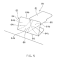
図5および図6は、それぞれ、容器の転がり防止用ストッパの組み立て状況を説明するための概略斜視図である。図7は、マルチパック用包装箱を4個、出荷カートンケース20内に納めた状態を模式的に示した概略斜視図である。図8は、マルチパック用包装箱の上面板側から見た平面図である。
FIG. 5 and FIG. 6 are schematic perspective views for explaining the assembly state of the stopper for preventing rolling of the container. FIG. 7 is a schematic perspective view schematically showing a state in which four multipack packaging boxes are stored in the
本発明における好適な実施の形態として、缶ビールを6個収納(直列した3缶を2列に並列させて収納)することができる一般的なマルチパック用包装箱1を一例にとって説明する。
As a preferred embodiment of the present invention, a general
本発明のマルチパック用包装箱1は、図1に示される展開シート(パック用シート)を組み立てることによって形成することができ、展開シートは、図1に示されるごとく横長の略矩形形状をなしている。
The
図1に示される展開シートにおいて、その中央部は上面板2を構成し、その両端にそれぞれ側面板3、4が連接されている。そして、側面板3の図面の左側部分には底面板5が形成され、側面板4の図面の右側部分には底面板6がそれぞれ形成されている。
In the unfolded sheet shown in FIG. 1, the central portion constitutes an
上面板2は、直列3個を並列2列に起立状態に整列させた缶ビール6個の上面を覆うように、図面の縦辺1a方向にはビール缶3缶分、横片1b方向にはビール缶2缶分の長さからなる面積を備えている。上面板2の両側には缶ビールの側部を覆うようにその高さに相当する側面板3、4がそれぞれ境界線をなす折り線2a、2bを介して連接されている。
The
底面板5および底面板6には、先端部の近傍で互いに係着し得る雌側の係止窓部7a(底面板5側)および雄側の係止部8a(底面板6側)がそれぞれ形成されている。図面の左側に位置している底面板5側の係止窓部7aは、図示のごとく縦辺1aに沿うように、中央とその両端側の3箇所にそれぞれ設けられている。この実施形態では、係止窓部7aの形状は切り抜かれた縦長の略四角孔となっていて、その孔の一辺aが実質的な係合部となっている。この一方で、図面の右側に位置している底面板6の雄側の係止部8aの形状は、縦辺1aに平行な直線で中央が内側に凹部bとなる切り込みとなっている。
The
これらの係着部位(係止部)に加えて、図面の左側に位置する底面板5側には、雌側の係止部7b、7cが形成され、これらとの関係において、図面の右側に位置する底面板6側には、雄側の係合片8b、8cがそれぞれ形成されている。図面の左側に位置する雌側の係止部7b、7cの形状は切り込みとなっている。図面の右側に位置する雄側の係合片8cの形状は、図示のごとく先端の茸状の頭部から顎部を形成するように絞られて首部dに至っている。なお、もう一方の雄側の係合片8b(図の上方側)は、係止部としても機能し得るが、主として、本発明の要部である容器の転がり防止用ストッパを組み立てる際の組立部材の一部品である形態固定用のフック片8bとして機能する。そのため、形態固定用のフック片8bは、底面から起立してフック機能を発揮するフック平面部81と、このフック平面部81を起立させる際の折り曲げ基部85を有し、フック平面部81は、折り曲げ基部85の端部から伸びる傾斜辺86と、この傾斜辺86の上部に形成された顎部87を有して形成される。これらの具体的機能については、後に詳述する。
In addition to these engaging portions (locking portions), female
側面板3、4の横辺1b側の各端部には、内側に折り込んで前記上面板2および底面板5、6の隅部との間にビール缶の脱落を防止するためのガゼット10a、10bを構成する折り込み片9が境界線をなす折り線3b、4bを介して連接されている。なお、ガゼット10a、10bの状態は例えば、図2に分かりやすく示されている。折り込み片9の折り目3b、4bには、内側に折り易くするために切り込み(スリット)を入れることが望ましい。
At each end of the
上述した底面板5、6に設けられた係止部を係着させることにより、缶ビール等の容器19群を包むように収納できるマルチパック用包装箱1が組立てられる。そして、図2〜図4に示されるようにマルチパック用包装箱1の側面板3、4が存在しない両端部において容器群の一部の側面が覗く第1の開口部P1、および第2の開口部P2が、それぞれ、形成される。第1の開口部P1とは、本発明を説明する上での便宜上、実質的に引き裂き除去可能な引裂き開口片が形成されている側をいい、第2の開口部P2とは、本発明を説明する上での便宜上、実質的に容器の転がり防止用ストッパが形成されている側をいう。
By engaging the locking portions provided on the
本発明の実施形態における上面板2は、その第1および第2の開口部P1、P2側において、容器の天面蓋の周縁に形成されているリング状突起95の一部が覗くように切り欠き部50が形成されている(図1、図8参照)。
In the embodiment of the present invention, the
このような切り欠き部50は、缶製品の引き出しが出来るだけ簡易にかつ容易に行えるように形成されている(取り出し容易性の向上)。すなわち、図8に示されるように、覗いているリング状突起95の一部を指先端に引っ掛けて引っ張ることにより、比較的容易に缶ビールを取り出すことが可能となる。
Such a
このような切り欠き部50の形状は、湾曲形状をなすことが特に好ましく、当該切り欠き部50の個数は、開口部Pから覗く容器の数に対応して同じ個数形成されることが望ましい。ただし、本発明において、切り欠き部50の存在は必須のものではなく、切り欠き部50を備えていないマルチパック用包装箱であってもよいことは勿論である。
It is particularly preferable that the shape of the
なお、図1における、符号13はコンプレッションホール(6箇所)、符号14aは山折り線、符号14bは谷折り線をそれぞれ表している。符号16はフィンガーホール(2箇所)、符号17は切り取り線をそれぞれ表している。上面板2に符号17で示されている切り取り線は、上面引裂き開口片を形成している。図1の符号17a側から上面引裂き開口片の引き剥がし操作が開始されるようになっている。
In FIG. 1,
(本発明の第1の要部構造の説明)
本発明の第1の要部は、側面板3および/または側面板4に、側面板の所定の奥側位置から手前位置である第1の開口部P1に向けて、引き裂き除去可能な引裂き開口片が形成されている点にある。本実施例においては、片方の側面板4に引裂き開口片40が形成されている場合が例示してある。本発明における奥側位置とは、開口部P1から側面板の中ほどに進んだ箇所、例えば、符号41で示される付近を示している。
(Description of the first essential structure of the present invention)
The first main part of the present invention is a tear opening that can be removed by tearing from the predetermined depth side position of the side plate toward the first opening P1 that is the front side of the
引裂き開口片40は、図1に示されるように引き裂き除去される形態に沿って不連続な切り込み線が形成されており、引き裂き除去の際の切り込み線の最終端47a,47aが、それぞれ開口部P1の端部近傍に形成されている折り込み片9の折り線4bの両端に実質的に向けられて形成されている。
As shown in FIG. 1, the
ここで、『実質的に向けられて形成されている』とは、容器の取り出し口を形成するために引裂き開口片40を除去する際に折り込み片9の折り線4bの両端を経由して、開口片40が除去されるようになっていることを意味する。これによって、引裂き開口片40を包装箱本体から容易に引き離すことができる。
Here, "substantially directed and formed" means that when the
引裂き除去操作に際し、引裂き開口片40が折り込み片9の折り線4bの両端の位置まで来た後は、引裂き抵抗はほとんどないため、その後、いっきに引裂き開口片40を引き裂き除去することができる。
In the tear removal operation, after the
引裂き開口片40の切り取られる形状は、図示のごとく奥側位置から開口部P1に向けて、その引き裂き幅が漸増的に広幅となるように形成されることが好ましい。引裂き開口片40を取り除いた後に、取り除いた側から手を挿入して包装箱本体内部の製品を取り易くするためである。
The shape of the
さらに、引裂き開口片40の形状について詳述すると、図1および図2に示されるように引裂き開口片40は、奥側位置付近に形成された引き裂き開始窓41と、これに連接し開口部側へ延びる引き裂き領域形成部45を有している。
Further, the shape of the
引き裂き開始窓41は、指が挿入できる程度の大きさの穴が開いており、開口の開始を容易にしている。引き裂き領域形成部45は、引き裂き開始窓41へ指を挿入するとともに箱外部からの押圧ないし引っ張りにより内側へのフラップ状の折込による凹みが形成できる領域45aを有しており、この凹み領域を把持部分として第1の開口部P1側への引き裂きをすることができるようになっている。引き裂き開始窓41の更に奥には、引き裂き開始窓41に向かう3本の切り取り線31、32、33が形成されており、これにより、引き裂き開始窓41への指の挿入を補助する機能、および開口した後に、容器の取り出しを容易にする機能(奥の位置する容器を取り出す時に指をいれることができる)を発揮することができる。
The tear start
引き裂き領域形成部45の構成について、さらに詳細に説明する。
The configuration of the tear
本実施形態における引き裂き領域形成部45は、引裂き開口片40の先端近傍を形成する湾曲部46と、この湾曲部46に連接して開口部P1側に向かう切り取り領域47と、湾曲部46を弧状として描くように形成された折り線部E(図面においては2本の折り線部)を有している。折り線部Eは、前述のフラップ状の折込による凹み領域45aを形成する際のフラップ片の基部として作用することができる。
The tear
この折り線部Eの存在により、フラップ状の折込により形成された凹み領域45aがそのままの形態を維持しやすくなり(すなわち、凹みがもとの平面状態に戻り難くなる)、把持操作を簡単に行なうことができる。
Due to the presence of the fold line portion E, the recessed
また、引き裂き開始窓41は、把持操作を確実に行うために、包装箱に収納される容器との関係において、容器が隣接する際に生じる隙間位置に存在するように形成されることが望ましい。すなわち、マルチパック用包装箱に収納される缶ビール容器が包装箱底部に立設されるように配置され、2×3の配列状態(例えば図2に示されるように開口部P1に2個見える)で収納されている場合、引き裂き開始窓41は、容器同士が隣接する際に生じる隙間位置(谷部空間)に存在するように形成されることが好ましい。
In addition, the tear start
上記の配置形態の場合、1個目の容器と2個目の容器との接触部位、2個目の容器と3個目の容器との接触部位の2箇所に隙間位置(谷部空間)に存在することになる。いずれの隙間位置(谷部空間)に引き裂き開始窓41を形成してもよいが、箱強度や引き裂き操作のやり易さ等を考慮すれば、開口部P1から最初の隙間位置(谷部空間)に引き裂き開始窓41を形成するようにすることが望ましい。
In the case of the above arrangement form, the contact portion between the first container and the second container and the contact portion between the second container and the third container are located at gap positions (valley spaces). Will exist. The tear start
なお、隙間位置(谷部空間)は、図8の平面図に明瞭に示されているのでこの図面を参照してご理解頂きたい。図8は、上述したように組み立てられたマルチパック用包装箱の上面板2側から見た平面図である。
The gap position (valley space) is clearly shown in the plan view of FIG. 8 and should be understood with reference to this drawing. FIG. 8 is a plan view of the multipack packaging box assembled as described above, as viewed from the
また、図1に示されるごとく引き裂き開始窓41の両脇から連接されている湾曲部46は、点線状の切り込み線によって形取られて構成するのが良い。また、湾曲部46に連接する切り取り領域47は、『へ』の字状の切り込み線、すなわち切り取り領域47を形取る点線状の切り込み線部分と、この点線状の切り込み線部分の奥側位置に連接すると共に、引裂き開口片の内側に切り込まれた線部を備える『へ』の字状の切り込み線により形成するのが良い。ただし、『へ』の字状の切り込み線に限定されることなく、例えば、点線状やY字状等の他の切り込み形状としてもよい。
Further, as shown in FIG. 1, the
また、上述してきた図1および図2に示されるような引裂き開口片は、例えば、図3に示されるような形態の引裂き開口片に改変してもよい。 Further, the tear opening piece as shown in FIGS. 1 and 2 described above may be modified to a tear opening piece having a form as shown in FIG. 3, for example.
図3に示される引裂き開口片40が図2に示されるそれと大きく異なる点は、図3の形態では図2のごとく引き裂き開始窓41が形成されておらず、最初から指を挿入するための開口された穴は存在しないところにある。すなわち、図3に示される引裂き開口片は、奥側位置付近に形成された引き裂き開始窓形成部42と、これに連接し第1の開口部P1側へ延びる引き裂き領域43を有し、引き裂き開始窓形成部42は、箱外部からの押圧により内側へのフラップ状の折込による凹み(開口)が形成できるようになっており、この凹みを把持部分として開口部側への引き裂き開始ができるようになっている。
The
なお、引き裂き除去可能な引裂き開口片40を最後まで切り取りやすい形状とするために、図1に示されるように、折り線4bの両端と、折り線14b、14bとが交わる近傍の位置に通常形成されるガセットの穴は、本願発明では形成されていない。
In order to make the
ガセットの穴がある場合には、引裂き開口片を切り取った場合に、ガセットの一部が切り取られずに残ってしまい、容器を取り出しにくい。ガセットの穴を無くすことにより、引裂き開口片を切り取った場合にガセットを全部切り取ることができるので、容器は格段と取り出しやすくなる。 When there is a gusset hole, when the tear opening piece is cut off, a part of the gusset remains without being cut out, and it is difficult to take out the container. By eliminating the gusset holes, the entire gusset can be cut out when the tear opening piece is cut out, making the container much easier to remove.
(本発明の第2の要部構造の説明)
本発明の第2の要部は、図4に示されるように底面板の第2の開口部P2に近い位置に、箱の内側に凸状に突出した容器の転がり防止用ストッパ60が組み立てられて形成されているところにある。
(Description of Second Essential Structure of the Present Invention)
As shown in FIG. 4, the second main part of the present invention is assembled with a
この容器の転がり防止用ストッパ60は、主として、図4に見られるように第2の開口部P2に最も近い容器(第1の開口部P1を基準にした場合に最後部の容器に相当する)が、第2の開口部P2から外に(図4の手前側方向に)転がり出ることを防止するために形成されている。
The container rolling
容器の転がり防止用ストッパ60は、前述した引き裂き除去可能な引裂き開口片40を設ける側とは反対方向の第2の開口部P2に近い位置に形成される。引裂き開口片40が設けられる第1の開口部P1側は、本来の容器の取り出し口に相当しており、これと全く反対位置の第2の開口部P2は最後部の開口に該当しており、第1の開口部P1側からの容器の取り出しの際に、最後部に位置する容器がさらに後方に転がり出ることを防止するために容器の転がり防止用ストッパ60が形成されている。すなわち、図4に示されるように容器の転がり防止用ストッパ60は、第2の開口部P2側に位置する最後部の2つの容器19の底部周縁と係合するように、2つの容器の間に凸状に突出して形成されている。
The container rolling
このような容器の転がり防止用ストッパ60の組み立て部材について、図面を参照しつつ、さらに詳細に説明する。
The assembly member of the container rolling
容器の転がり防止用ストッパ60は、図1の左上方に図示されている底面板5に形成された折り曲げ片61と、図1の右上方端に図示されている底面板6の雄側の係合片8b(形態固定用のフック片8b)と、の組み立てにより形成されている。
The
図1に示されるように折り曲げ片61は、コの字状に打ち抜かれた打ち抜き平面部分64と、この打ち抜き平面部分の2つの終端64a,64aを結ぶ折り曲げ部66とを有し構成されている。
As shown in FIG. 1, the
打ち抜き平面部分64には、2つの終端64a,64aから折り曲げ部66と平行配置されている打ち抜き対向ライン64bのほぼ中点に向けてストッパ形成用折れ線64c,64cが形成されている。このようなストッパ形成用折れ線64c,64cによって、打ち抜き平面部分64は、2つの三角状の折り片64d,64dと、これら2つの三角状の折り片64d,64dと連接して基台となる三角状基台64eとが形成される。ストッパ形成用折れ線64c,64cは、厳密には、三角状基台64e側にわずかに膨らんだ湾曲ラインとなっている。
The punching
このような打ち抜き平面部分64と展開図において反対側に位置している形態固定用として用いられるフック片8bについてさらに詳細に説明すると、形態固定用のフック片8bは、図1に示されるようにフック機能を発揮するフック平面部81と、このフック平面部81を起立させる際の折り曲げ基部85を有している。そして、フック平面部81は、折り曲げ基部85の端部(外側基部)から伸びる傾斜辺86と、この傾斜辺86の上部に形成された顎部87を有している。顎部87は、後述するように逆V字凸状に折られた打ち抜き対向ライン64bの頂点近傍の凸部と係合できるようになっている。
The
このような容器の転がり防止用ストッパ60の組み立て手順の一例について、以下、詳細に説明する。なお、この手順は、あくまで一例であり、この手順に限定されるものではない。
Hereinafter, an example of an assembly procedure of the container rolling
マルチパック用包装箱を組み立てる際に、図1の右側に示されるフック片8bを図1の左側に示される雌側の係止部7bに挿通させる(この際、同様に図1の右側に位置する雄側の係合片8cも図1の左側に位置する雌側の係止部7cに挿通させている)。
When assembling the multi-pack packaging box, the
その後、挿通したフック片8bを折り曲げ基部85を基線として(フック片8bの)フック平面部81折り曲げて起こす操作が行われる。さらに、底面板5をコの字状に打ち抜かれた打ち抜き平面部分64を折り曲げ部66から起こす操作が行われる。これらの操作はいずれを先に行っても良く、また、同時に行なうようにしてもよい。これらの操作が完了した状態が図5に示されており、フック平面部81および平面部分64(折り曲げ片61)がそれぞれ折り曲げ操作により起立されている。
Thereafter, the
次いで、折り曲げ部66から起された折り曲げ片61の打ち抜き対向ライン64bを逆V字状の山折りに折りつつ、ストッパ形成用折れ線64c,64cを内側に折り曲げる(いわゆる山折りする)。すると、2つの三角状の折り片64d,64dと、これら2つの三角状の折り片64d,64dと連接して基台となる三角状基台64eとが形成される。しかる後、逆V字に折られた打ち抜き対向ライン64bの実質的な中点(逆V字の頂点近傍)に、前記形態固定用のフック片8bの顎部87を係止させて箱の内側に凸状に突出した容器の転がり防止用ストッパが組み立てられる。この組み立て後の状態が図6に示される。
Next, the stopper forming
なお、フック片8bの傾斜辺86は、容器の転がり防止用ストッパを組み立てる際に三角状基台64eを構成する面(図6の内面)と接することができるようになっている(図6参照)。これによって、斜めに起された三角状基台64eの傾斜位置が固定され、容器の転がり防止用ストッパの形態の安定化を図ることができるようになっている。
The
このように形成された転がり防止用ストッパ60における2つの三角状の折り片64d,64dは、容器の底部周縁と係合するとともに(図4参照)、起立したフック平面部81は、2つの容器の間に介在される。
The two triangular folded
なお、上記の実施形態では、2×3配列のいわゆる6缶マルチパック用包装箱について説明してきたが、2×4配列のいわゆる8缶マルチパック用包装箱についても同様に適用することができる。8缶マルチパック用包装箱の場合、1個目の容器と2個目の容器との接触部位、2個目の容器と3個目の容器との接触部位、3個目の容器と4個目の容器との接触部位の3箇所に隙間位置(谷部空間)に存在することになる。いずれの隙間位置(谷部空間)に引き裂き開始窓や引き裂き開始窓形成部を形成してもよいが、この場合もやはり第1の開口部P1から最初の隙間位置(谷部空間)に引き裂き開始窓や引き裂き開始窓形成部を形成するようにすることが望ましい。 In the above-described embodiment, a so-called 6-can multipack packaging box having a 2 × 3 arrangement has been described. However, the same can be applied to a so-called 8-can multipack packaging box having a 2 × 4 arrangement. In the case of an 8-can multipack packaging box, the contact area between the first container and the second container, the contact area between the second container and the third container, the third container and the four containers It exists in a clearance gap position (valley part space) in three places of contact parts with an eye container. A tear start window or a tear start window forming portion may be formed in any gap position (valley space), but in this case as well, tearing starts from the first opening P1 to the first gap position (valley space). It is desirable to form a window and a tear start window forming part.
(具体的包装作用の一例の説明)
次に具体的包装作用の一例を説明する。まず、図1に示されるパック用シートを裏返して、その上面板2の部分の上部に缶ビール6本の底部を上向きとして直列した3缶を2列に並列させて載置する。
(Description of an example of specific packaging action)
Next, an example of a specific packaging operation will be described. First, the pack sheet shown in FIG. 1 is turned upside down, and three cans arranged in series with the bottom of six can beers facing upward are placed in parallel in two rows on the upper portion of the
その上で、缶ビールの側部を覆うように側面板3、4を折り線2a、2bを境界線として内側に折り、各折り込み片9を内側に折り込み、上面板2と側面板3、4との隅部にトップガゼット10aを、また側面板3、4と底面板5、6との隅部にボトムガゼット10bをそれぞれ形成し、さらに缶ビールの底部を覆うように底面板5および6を折り線3a、4aを境界線として内側に折り、底面板6に設けられている雄側の第1係止部8aの凹部bを底面板5の雌側の第1係止部7aの横長の四角孔を形成する一辺aに係着させることにより缶ビールを包装する。その係着が脱落しないように、底面板6に設けられている形態固定用のフック片8bおよび雄側の係合片8cをそれぞれ、頭部から底面板5に設けられている雌側の係止部7bおよび7cのスリットを通して互いに係着させてフック片8bおよび係合片8cの首部dで抜け止めする。
Then, the
次いで、容器の転がり防止用ストッパ60が、例えば、前述した組み立て手順に従って組み立てられる。
Next, the
パック用シート1を側面板4が上になるように反転させると図2に示されるような斜視図の形態となる。
When the
なお、上述のマルチパック用包装箱に容器を収納することによりマルチパック包装製品が出来あがる。 In addition, a multipack packaged product is completed by storing a container in the above-mentioned multipack packaging box.
(引裂き開口片40を除去する操作の一例の説明)
図2に示されるような横置きの状態で、かつ、第1の開口部P1を手前側にして棚の中に挿入されたマルチパック用包装箱の引裂き開口片40を引き裂き除去するには、引き裂き開始窓41へ指を挿入したまま手前に引っ張り開口部側への引き裂きを完了させるか、あるいは、引き裂き開始窓41へ指を挿入した状態で、さらに下方手前に押圧を加えてフラップ状の折込による凹みを形成し、この凹みを把持部分として開口部側への引き裂きを完了させる等の好適な操作が行われる。
(Description of an example of operation for removing the tear opening piece 40)
To tear and remove the
なお、本発明における実施形態では缶ビールの包装を例にとって説明したが、このものに限定されるものではない。例えば、発泡酒缶、チューハイ缶等のアルコール飲料缶や、缶ジュース、缶コーヒー、缶紅茶、缶入り茶等のノンアルコール飲料缶などその他の各種缶製品にも適用できることは勿論のことである。 In addition, although embodiment of this invention demonstrated taking the packaging of canned beer as an example, it is not limited to this. For example, it can be applied to other various can products such as non-alcoholic beverage cans such as alcoholic beverage cans such as sparkling liquor cans and Chu-hi cans, can juice, canned coffee, canned tea and canned tea.
本発明のマルチパック用包装箱は、例えば缶ビール、発泡酒缶、チューハイ缶等のアルコール飲料缶や、缶ジュース、缶コーヒー、缶紅茶、缶入り茶等ノンアルコール飲料缶等の一定数量の容器を包装するための包装箱であり、包装産業一般に利用することができる。 The multi-pack packaging box of the present invention is a container of a certain quantity such as a non-alcoholic beverage can such as canned beer, canned liquor can, Chu-Hi can, canned juice, canned coffee, canned tea, canned tea, etc. It is a packaging box for packaging and can be used for the packaging industry in general.
1…マルチパック用包装箱
2…上面板
3、4…側面板
5、6…底面板
8b…形態固定用のフック片
40…引裂き開口片
41…引き裂き開始窓
45…引き裂き領域形成部
50…切り欠き部
60…容器の転がり防止用ストッパ
61…折り曲げ片
64…打抜き平面部分
64b…打抜き対向ライン
64c,64c…ストッパ形成用折れ線
64d,64d…三角状の折り片
64e…三角状基台
66…折り曲げ部
P1…第1の開口部
P2…第2の開口部
DESCRIPTION OF
Claims (10)
この上面板の両側部に連接され並列された各容器の側面を覆うように配置された対向する側面板と、
これら側面板に連接され互いに係着しうる係止部を有する底面板とを備え、前記底面板を係着することにより前記容器群を包むように収納することができるとともに、側面板が存在しない両端部において容器群の一部の側面が覗く第1の開口部および第2の開口部が形成されるマルチパック用包装箱において、
前記側面板には、側面板の所定の奥側位置から手前位置である第1の開口部に向けて、引き裂き除去可能な引裂き開口片が少なくとも1つ形成されており、
前記側面板に形成された引裂き開口片は、引き裂き除去される形状に沿って不連続な切り込み線が形成されており、引き裂き除去の際の切り込み線の最終端が、第1の開口部の近傍に形成されている折り込み片の折り線の両端に実質的に向けられて形成されており、
前記底面板の前記第2の開口部に近い位置には、箱の内側に凸状に突出した容器の転がり防止用ストッパが形成されていることを特徴とするマルチパック用包装箱。 An upper surface plate covering the upper surface of a plurality of containers arranged in parallel;
Opposing side plates arranged so as to cover the side surfaces of the containers connected to both sides of the upper plate and arranged in parallel,
A bottom plate having a locking portion that is connected to the side plates and can be engaged with each other, and can be accommodated so as to wrap the container group by engaging the bottom plate, and both ends where the side plate does not exist In the multi-pack packaging box in which the first opening and the second opening through which a part of the side surface of the container group is peeked are formed,
The side plate is formed with at least one tear opening piece that can be removed by tearing from the predetermined back side position of the side plate toward the first opening that is the near side,
The tear opening piece formed on the side plate has a discontinuous cut line formed along the shape to be removed by tearing, and the final end of the cut line at the time of tear removal is in the vicinity of the first opening. Formed substantially toward both ends of the fold line of the folding piece formed in
A multi-pack packaging box, wherein a stopper for preventing the rolling of the container projecting in a convex shape is formed inside the box at a position near the second opening of the bottom plate.
前記折り曲げ片は、コの字状に打ち抜かれた打ち抜き平面部分と、この打ち抜き平面部分の2つの終端を結ぶ折り曲げ部とを有し、
前記打ち抜き平面部分には、前記2つの終端から、それぞれ、前記折り曲げ部と平行配置されている打ち抜き対向ラインの中点に向けてストッパ形成用折れ線が形成されており、
前記打ち抜き対向ラインを逆V字状に折りつつストッパ形成用折れ線を内側に折り曲げて、2つの三角状の折り片と、これら2つの三角状の折り片と連接して基台となる三角状基台とを形成するととともに、折り曲げ片を折り曲げ部から起こし、しかる後、逆V字に折られた打ち抜き対向ラインの実質的な中点(逆V字の頂点近傍)に、前記形態固定用のフック片を係止させて箱の内側に凸状に突出した容器の転がり防止用ストッパを組み立て形成してなる請求項1に記載のマルチパック用包装箱。 The stopper for preventing rolling of the container is formed by assembling a bent piece formed on the bottom plate and a hook piece for fixing the form,
The bent piece has a punched plane portion punched into a U-shape and a bent portion connecting two terminal ends of the punched plane portion;
The punching plane part is formed with a stopper forming bent line from the two end points toward the midpoint of the punching opposing line arranged in parallel with the bent portion, respectively.
The stopper forming fold line is folded inward while folding the punching opposing line in an inverted V shape, and two triangular folds, and a triangular base that is connected to the two triangular folds and serves as a base And forming the pedestal, raising the bent piece from the bent portion, and then, at the substantial midpoint (near the apex of the inverted V-shape) of the punching opposing line folded in an inverted V shape, The multi-pack packaging box according to claim 1, wherein the stopper is for assembling and forming a stopper for preventing the rolling of the container projecting in a convex shape inside the box by locking the pieces.
前記フック平面部は、折り曲げ基部の端部から伸びる傾斜辺と、この傾斜辺の上部に形成された顎部を有し、
前記顎部は前記逆V字凸状に折られた打ち抜き対向ラインの実質的な中点(逆V字の頂点近傍)と係合できるようになっており、
前記傾斜辺は、前記三角状基台を構成する面と接することができるようになっている請求項3に記載のマルチパック用包装箱。 The hook piece for form fixing has a hook plane part that stands up from the bottom surface and exhibits a hook function, and a bent base part when the hook plane part is raised,
The hook plane part has an inclined side extending from the end of the bent base and a jaw part formed on the upper side of the inclined side,
The jaw portion can be engaged with a substantial midpoint (near the vertex of the inverted V-shape) of the punched opposing line folded into the inverted V-shaped convex shape,
The multi-pack packaging box according to claim 3, wherein the inclined side can come into contact with a surface constituting the triangular base.
前記引き裂き領域形成部は、箱外部からの押圧ないし引っ張りにより内側へのフラップ状の折込による凹みが形成できる領域を備えており、この凹みを把持部分として第1の開口部側への引き裂きをすることができるようになっている請求項1ないし請求項6のいずれかに記載のマルチパック用包装箱。 The tear opening piece has a tear start window formed in the vicinity of the back side position, and a tear region forming portion connected to this and extending to the first opening side,
The tear region forming portion includes a region in which a recess can be formed by folding or folding inward by pressing or pulling from the outside of the box, and tearing toward the first opening is performed using the recess as a grip portion. The multipack packaging box according to any one of claims 1 to 6 , wherein the packaging box can be used.
前記引き裂き開始窓形成部は、箱外部からの押圧により内側へのフラップ状の折込による凹みが形成できるようになっており、この凹みを把持部分として第1の開口部側への引き裂き開始ができるようになっている請求項1ないし請求項6のいずれかに記載のマルチパック用包装箱。 The tear opening piece has a tear start window forming portion formed in the vicinity of the back side position, and a tear region connected to this and extending to the opening portion side,
The tear start window forming portion is configured to be able to form a recess by a flap-like folding inward by pressing from the outside of the box, and can start tearing toward the first opening using the recess as a grip portion. The multipack packaging box according to any one of claims 1 to 6 , which is configured as described above.
Priority Applications (1)
| Application Number | Priority Date | Filing Date | Title |
|---|---|---|---|
| JP2006131020A JP4891649B2 (en) | 2006-05-10 | 2006-05-10 | Multipack packaging box |
Applications Claiming Priority (1)
| Application Number | Priority Date | Filing Date | Title |
|---|---|---|---|
| JP2006131020A JP4891649B2 (en) | 2006-05-10 | 2006-05-10 | Multipack packaging box |
Publications (2)
| Publication Number | Publication Date |
|---|---|
| JP2007302275A JP2007302275A (en) | 2007-11-22 |
| JP4891649B2 true JP4891649B2 (en) | 2012-03-07 |
Family
ID=38836558
Family Applications (1)
| Application Number | Title | Priority Date | Filing Date |
|---|---|---|---|
| JP2006131020A Expired - Fee Related JP4891649B2 (en) | 2006-05-10 | 2006-05-10 | Multipack packaging box |
Country Status (1)
| Country | Link |
|---|---|
| JP (1) | JP4891649B2 (en) |
Families Citing this family (1)
| Publication number | Priority date | Publication date | Assignee | Title |
|---|---|---|---|---|
| JP5588192B2 (en) * | 2010-02-19 | 2014-09-10 | サッポロビール株式会社 | Multipack and multipack deployment |
Family Cites Families (1)
| Publication number | Priority date | Publication date | Assignee | Title |
|---|---|---|---|---|
| JPS5016854Y1 (en) * | 1970-06-18 | 1975-05-24 |
-
2006
- 2006-05-10 JP JP2006131020A patent/JP4891649B2/en not_active Expired - Fee Related
Also Published As
| Publication number | Publication date |
|---|---|
| JP2007302275A (en) | 2007-11-22 |
Similar Documents
| Publication | Publication Date | Title |
|---|---|---|
| EP1682418B1 (en) | Dispensing package | |
| US7413101B2 (en) | Dispensing package | |
| US7225930B2 (en) | Combination shipping carton and twin dispenser boxes | |
| US3257066A (en) | Carton for containers or the like | |
| JP3197408U (en) | Packaging display box | |
| US9096344B1 (en) | Carton with corner dispenser | |
| EP2765085A1 (en) | Shipping and display container foldable into display trays with anti-tip features and blank therefor | |
| JP4891649B2 (en) | Multipack packaging box | |
| JP5315530B2 (en) | Multipack packaging box | |
| US7014044B1 (en) | Cup and lid holder and dispenser | |
| EP2174876B1 (en) | Carton configurable for displaying contents | |
| JP4891650B2 (en) | Multipack packaging box | |
| JP4369856B2 (en) | Multipack packaging box | |
| JP4099038B2 (en) | Multipack packaging box | |
| JP2711743B2 (en) | Packaging box for beverage cans, etc. | |
| US20040040877A1 (en) | Container for providing easy access to beverage cans | |
| JP3820214B2 (en) | Multipack packaging box | |
| JP3376488B2 (en) | Packaging box for square cylindrical round bottles | |
| JP3680104B2 (en) | Pack sheet | |
| JP6825867B2 (en) | Packaging box for multi-pack | |
| WO2011052487A1 (en) | Multi packaging box | |
| US20050258223A1 (en) | Carton and a blank therefor | |
| JP3540207B2 (en) | Pack sheet | |
| JP2002362627A (en) | Insert-to-attach piece and multipack package using the same | |
| JPH10101061A (en) | Dozen container packaging carton |
Legal Events
| Date | Code | Title | Description |
|---|---|---|---|
| A711 | Notification of change in applicant |
Free format text: JAPANESE INTERMEDIATE CODE: A712 Effective date: 20070730 |
|
| RD03 | Notification of appointment of power of attorney |
Free format text: JAPANESE INTERMEDIATE CODE: A7423 Effective date: 20071005 |
|
| A621 | Written request for application examination |
Free format text: JAPANESE INTERMEDIATE CODE: A621 Effective date: 20090424 |
|
| A977 | Report on retrieval |
Free format text: JAPANESE INTERMEDIATE CODE: A971007 Effective date: 20110914 |
|
| A131 | Notification of reasons for refusal |
Free format text: JAPANESE INTERMEDIATE CODE: A131 Effective date: 20110927 |
|
| A521 | Written amendment |
Free format text: JAPANESE INTERMEDIATE CODE: A523 Effective date: 20111122 |
|
| TRDD | Decision of grant or rejection written | ||
| A01 | Written decision to grant a patent or to grant a registration (utility model) |
Free format text: JAPANESE INTERMEDIATE CODE: A01 Effective date: 20111213 |
|
| A01 | Written decision to grant a patent or to grant a registration (utility model) |
Free format text: JAPANESE INTERMEDIATE CODE: A01 |
|
| A61 | First payment of annual fees (during grant procedure) |
Free format text: JAPANESE INTERMEDIATE CODE: A61 Effective date: 20111216 |
|
| R150 | Certificate of patent or registration of utility model |
Free format text: JAPANESE INTERMEDIATE CODE: R150 |
|
| FPAY | Renewal fee payment (event date is renewal date of database) |
Free format text: PAYMENT UNTIL: 20141222 Year of fee payment: 3 |
|
| R250 | Receipt of annual fees |
Free format text: JAPANESE INTERMEDIATE CODE: R250 |
|
| LAPS | Cancellation because of no payment of annual fees |