JP4886586B2 - Liquid storage container, head cartridge, inkjet recording apparatus, and liquid storage container stirring method - Google Patents
Liquid storage container, head cartridge, inkjet recording apparatus, and liquid storage container stirring method Download PDFInfo
- Publication number
- JP4886586B2 JP4886586B2 JP2007119912A JP2007119912A JP4886586B2 JP 4886586 B2 JP4886586 B2 JP 4886586B2 JP 2007119912 A JP2007119912 A JP 2007119912A JP 2007119912 A JP2007119912 A JP 2007119912A JP 4886586 B2 JP4886586 B2 JP 4886586B2
- Authority
- JP
- Japan
- Prior art keywords
- ink
- liquid
- opening
- stirring member
- stirring
- Prior art date
- Legal status (The legal status is an assumption and is not a legal conclusion. Google has not performed a legal analysis and makes no representation as to the accuracy of the status listed.)
- Expired - Fee Related
Links
Images


Classifications
-
- B—PERFORMING OPERATIONS; TRANSPORTING
- B01—PHYSICAL OR CHEMICAL PROCESSES OR APPARATUS IN GENERAL
- B01F—MIXING, e.g. DISSOLVING, EMULSIFYING OR DISPERSING
- B01F31/00—Mixers with shaking, oscillating, or vibrating mechanisms
- B01F31/20—Mixing the contents of independent containers, e.g. test tubes
- B01F31/24—Mixing the contents of independent containers, e.g. test tubes the containers being submitted to a rectilinear movement
-
- B—PERFORMING OPERATIONS; TRANSPORTING
- B01—PHYSICAL OR CHEMICAL PROCESSES OR APPARATUS IN GENERAL
- B01F—MIXING, e.g. DISSOLVING, EMULSIFYING OR DISPERSING
- B01F31/00—Mixers with shaking, oscillating, or vibrating mechanisms
- B01F31/42—Mixers with shaking, oscillating, or vibrating mechanisms with pendulum stirrers, i.e. with stirrers suspended so as to oscillate about fixed points or axes
-
- B—PERFORMING OPERATIONS; TRANSPORTING
- B41—PRINTING; LINING MACHINES; TYPEWRITERS; STAMPS
- B41J—TYPEWRITERS; SELECTIVE PRINTING MECHANISMS, i.e. MECHANISMS PRINTING OTHERWISE THAN FROM A FORME; CORRECTION OF TYPOGRAPHICAL ERRORS
- B41J2/00—Typewriters or selective printing mechanisms characterised by the printing or marking process for which they are designed
- B41J2/005—Typewriters or selective printing mechanisms characterised by the printing or marking process for which they are designed characterised by bringing liquid or particles selectively into contact with a printing material
- B41J2/01—Ink jet
- B41J2/17—Ink jet characterised by ink handling
- B41J2/1707—Conditioning of the inside of ink supply circuits, e.g. flushing during start-up or shut-down
-
- B—PERFORMING OPERATIONS; TRANSPORTING
- B41—PRINTING; LINING MACHINES; TYPEWRITERS; STAMPS
- B41J—TYPEWRITERS; SELECTIVE PRINTING MECHANISMS, i.e. MECHANISMS PRINTING OTHERWISE THAN FROM A FORME; CORRECTION OF TYPOGRAPHICAL ERRORS
- B41J2/00—Typewriters or selective printing mechanisms characterised by the printing or marking process for which they are designed
- B41J2/005—Typewriters or selective printing mechanisms characterised by the printing or marking process for which they are designed characterised by bringing liquid or particles selectively into contact with a printing material
- B41J2/01—Ink jet
- B41J2/17—Ink jet characterised by ink handling
- B41J2/175—Ink supply systems ; Circuit parts therefor
- B41J2/17503—Ink cartridges
- B41J2/17513—Inner structure
- B41J2002/17516—Inner structure comprising a collapsible ink holder, e.g. a flexible bag
Landscapes
- Chemical & Material Sciences (AREA)
- Chemical Kinetics & Catalysis (AREA)
- Ink Jet (AREA)
- Particle Formation And Scattering Control In Inkjet Printers (AREA)
Abstract
Description
本発明は、インクなどの液体を収納する液体収納容器、その液体収納容器を備えるヘッドカートリッジ、その液体収納容器を用いて画像を記録可能なインクジェット記録装置、およびその液体収納容器内の液体の攪拌方法に関する。 The present invention relates to a liquid storage container for storing a liquid such as ink, a head cartridge including the liquid storage container, an ink jet recording apparatus capable of recording an image using the liquid storage container, and stirring of the liquid in the liquid storage container Regarding the method.
シリアルタイプのインクジェット記録装置は、主走査方向に移動可能なキャリッジに、インクを吐出可能な記録ヘッドと、その記録ヘッドに供給するインクを収容するためのインクタンクと、が搭載される。画像の記録に際しては、キャリッジを主走査方向に移動させつつ、記録ヘッドの吐出口から記録媒体に向かってインクを吐出する動作と、主走査方向と交差する副走査方向に記録媒体を搬送する動作と、を繰り返す。記録ヘッドから吐出されたインク滴が記録媒体上に着弾することにより、所望の画像が記録される。 In a serial type ink jet recording apparatus, a recording head capable of ejecting ink and an ink tank for containing ink to be supplied to the recording head are mounted on a carriage movable in the main scanning direction. When recording an image, the operation of ejecting ink from the ejection port of the recording head toward the recording medium while moving the carriage in the main scanning direction and the operation of conveying the recording medium in the sub-scanning direction intersecting the main scanning direction And repeat. A desired image is recorded by the ink droplets ejected from the recording head landing on the recording medium.
このようなインクジェット記録装置において用いられているインクの主流は、色材として染料を含有するインクであった。しかし一般に、染料インクは耐光性および耐ガス性がやや低く、その染料インクによる記録物は、屋外掲示のような特殊用途において耐久性のある画像堅牢性を提供しにくい場合があった。 The mainstream of ink used in such an ink jet recording apparatus is an ink containing a dye as a coloring material. However, in general, dye inks have slightly low light resistance and gas resistance, and recorded materials using the dye inks sometimes have difficulty in providing durable image fastness in special applications such as outdoor posting.
近年、色材として顔料を含有するインクを用いる記録装置が提供されてきている。顔料インクは耐光性および耐ガス性に優れ、それによる記録物も充分な画像堅牢性を発揮することができる。但し、顔料インクは、染料インクとは異なり、色材の分散性を考慮した取り扱いが要求される。均一な記録画像を得るためには、色材を溶媒中に分散させる必要がある。 In recent years, recording apparatuses using ink containing a pigment as a coloring material have been provided. The pigment ink is excellent in light resistance and gas resistance, and the recorded matter can also exhibit sufficient image fastness. However, unlike the dye ink, the pigment ink is required to be handled in consideration of the dispersibility of the color material. In order to obtain a uniform recorded image, it is necessary to disperse the color material in the solvent.
顔料インク中の顔料分子は、染料インク中の染料分子のようにインク溶液中には溶解せず、分散した状態で浮遊している。顔料インクを収容するインクタンクが暫く静置されたままであると、インクタンク内の顔料粒子が重力によって徐々に沈降し、インクタンクの高さ方向において顔料粒子の濃度傾斜が発生することがあった。すなわち、インクタンクの底部には色材濃度の高い層が位置し、その上部には色材濃度の低い層が位置することになる。この状態のインクタンクから記録ヘッドにインクを供給して画像の記録動作を開始し、そして記録動作を継続した場合には、記録動作の初期段階と後期段階において、画像に濃度差が発生するおそれがある。 The pigment molecules in the pigment ink do not dissolve in the ink solution like the dye molecules in the dye ink, but float in a dispersed state. If the ink tank containing the pigment ink is left standing for a while, the pigment particles in the ink tank gradually settle down due to gravity, and the concentration gradient of the pigment particles may occur in the height direction of the ink tank. . That is, a layer having a high color material density is located at the bottom of the ink tank, and a layer having a low color material density is located above the ink tank. When ink is supplied from the ink tank in this state to the recording head to start the image recording operation and the recording operation is continued, a difference in density may occur in the image between the initial stage and the later stage of the recording operation. There is.
具体的に説明するために、インクタンクの底部から記録ヘッドにインクを供給する構成のインクジェット記録装置を考える。この記録装置に、上述した顔料粒子の濃度傾斜を有するインクタンクを装着して記録を開始した場合、記録初期では、インクタンク内の下層の色材濃度の高いインクが供給されるため、必要以上に高濃度な画像が記録される。その後、記録動作を続行することにより、インクタンク内のインクの消費にしたがって、画像の記録濃度は徐々に低下する。そして、インクタンク内のインクが少量になった状態においては、インクタンク内には、当初の色材濃度よりも低い色材濃度のインクしか残存しなくなる。そのため、記録当初と同じ画像データに基づいて画像を記録した場合でも、記録濃度が薄いものとなる。特に、顔料粒子の径や比重が大きい場合、顔料粒子の沈降傾向が著しいため、インクタンクの非使用状態が数日間続くだけでも、画像に影響が現れるほどの濃度傾斜が発生するおそれがある。 In order to explain specifically, consider an ink jet recording apparatus configured to supply ink to the recording head from the bottom of the ink tank. When recording is started with the ink tank having the above-described gradient of pigment particle concentration in this recording apparatus, ink with a high colorant concentration in the lower layer in the ink tank is supplied at the initial stage of recording. High-density images are recorded on the. Thereafter, by continuing the recording operation, the recording density of the image gradually decreases as the ink in the ink tank is consumed. In a state where the amount of ink in the ink tank is small, only ink having a color material density lower than the original color material density remains in the ink tank. Therefore, even when an image is recorded based on the same image data as that at the beginning of recording, the recording density is low. In particular, when the diameter and specific gravity of the pigment particles are large, the sedimentation tendency of the pigment particles is remarkable. Therefore, even if the ink tank is not used for several days, there is a possibility that a density gradient that may affect the image may occur.
このように、インクタンクの使用に伴って、記録ヘッドから吐出されるインクの色材濃度が変化した場合、インクタンクの使用初期と使用後期において記録画像に濃度差を発生させるだけではない。例えば、複数のカラーインクを用い、所定のカラーバランスのもとに色相を表現するカラーインクジェット記録システムにでは、カラーバランスが崩れるおそれがある。この場合、より顕著な画像濃度差問題として認識されることになる。 As described above, when the color material density of the ink ejected from the recording head is changed with the use of the ink tank, not only the density difference is generated in the recorded image between the initial use stage and the later use stage of the ink tank. For example, in a color inkjet recording system that uses a plurality of color inks and expresses a hue based on a predetermined color balance, the color balance may be lost. In this case, it will be recognized as a more prominent image density difference problem.
インクタンク内に残存するインク量の如何に拘わらず、記録ヘッドから吐出されるインク滴の色材濃度を、一定の濃度範囲内に維持するためには、少なくとも記録動作中に、インクタンク内の顔料分子が一様に分散していることが望まれる。 Regardless of the amount of ink remaining in the ink tank, in order to maintain the color material concentration of the ink droplets ejected from the recording head within a certain density range, at least during the recording operation, It is desirable that the pigment molecules are uniformly dispersed.
このような顔料分子の一様な分散を実現するために、インクタンクの内部に、顔料分子を攪拌するための攪拌体を設ける構成が提案されている In order to realize such uniform dispersion of pigment molecules, a configuration in which a stirring body for stirring pigment molecules is provided inside the ink tank has been proposed.
特許文献1には、手動操作が可能な攪拌体を備えたインクパックが開示されている。この攪拌体は、インクパックに対して、外部から挿入される形状になっている。外部に突出している攪拌体の一部は、インクパック内に延在している攪拌体の攪拌部を動作させるための操作部として作用する。つまり、ユーザが定期的あるいは必要に応じて攪拌部を揺動させることにより、インクパック内のインクを攪拌して、顔料分子を分散できるようになっている。
また、特許文献1には、記録動作時にキャリッジが移動する際の慣性力を利用して、タンク内のインクを攪拌させる揺動部材を設けたインクカートリッジが開示されている。一例として、インクカートリッジケースと一体に成形された撹拌体が示されている。この例では、攪拌体がインクカートリッジケースの天井から底部に向けて垂れ下がるように延出し、その下端部に円柱状の錘部が形成されている。その攪拌体は、キャリッジの加速・停止・反転の動作に伴う慣性力によって、天井の付け根部分を支点としてキャリッジの移動方向に揺動し、インクカートリッジ内のインクを攪拌する。
また、特許文献1には、他の例として、インクカートリッジケースに固定されずに、インクカートリッジ内の底面を自由に移動可能な撹拌体も開示されている。この攪拌体は、キャリッジの加速・停止・反転の動作に伴う慣性力によって、インクカートリッジ内の底面を移動してインクを攪拌する。
In addition,
また、特許文献2には、キャリッジの移動に伴う慣性力によって、揺動中心軸の左右に揺動する軸状錘と、この軸状錘と一体になって左右に揺動する複数のフィンと、を備えた攪拌機構が開示されている。この構成によれば、複数枚のフィンがインクカートリッジの高さ方向に並列に配置されているため、インクカートリッジ内の上層部から下層部にかけてインクが均等に攪拌される。
しかしながら、上記特許文献に記載の構成においては、攪拌領域が限定されているため、沈降した顔料粒子を容器内部の全体に渡って攪拌するには、十分ではなく、効率が悪いものであった。 However, in the configuration described in the above-mentioned patent document, since the stirring region is limited, it is not sufficient to stir the settled pigment particles over the entire interior of the container, and the efficiency is poor.
例えば、特許文献1に記載された、手動式の揺動部材を備えた構成では、その揺動部材の動きの自由度が少ないことから、インクカートリッジ内の限られた領域のインクしか攪拌することができない。特に、攪拌部の支点となる攪拌体とインクカートリッジとの接合部分の近傍では、攪拌部の移動域が狭いために充分な攪拌効果が得られない。
For example, in the configuration provided with a manual swing member described in
また、特許文献1に開示された、円柱状の錘部を設けた構成では、慣性力を効率的に利用してはいるものの、やはり攪拌可能な範囲が充分でない。さらに、インクカートリッジ内の底面を自由に移動可能な撹拌体を用いた場合には、インクカートリッジの底部近傍のインクに対する攪拌は期待できるものの、その撹拌体から離れているカートリッジ上層部領域に対する撹拌性は期待できない。
Moreover, in the structure provided with the column-shaped weight part disclosed by
一方、特許文献2に開示された構成では、複数のフィンがインクカートリッジの高さ方向に配備されているため、高さ方向における攪拌の均等性はある程度期待できる。しかし、インクカートリッジ内の中心軸付近はフィンの揺動量が小さいため、撹拌効果は小さい。また、このように複数のフィンや回転軸を備える揺動部材は複雑な構成となるため、インクカートリッジ自体も高価なものになってしまう。
On the other hand, in the configuration disclosed in
上述したように、インクカートリッジ内における顔料インクは、顔料粒子が重力にしたがって徐々に沈降することにより、インクカートリッジの高さ方向に顔料粒子の濃度傾斜が生じる。インクカートリッジ内の濃度差を解消するには、インクカートリッジの下層に沈降する高濃度のインクを積極的に上層部に巻き上げるか、もしくは上層部の低濃度のインクを下層部に流し込むように、インクを攪拌することが効率的である。 As described above, the pigment ink in the ink cartridge has a concentration gradient of the pigment particles in the height direction of the ink cartridge as the pigment particles gradually settle according to gravity. In order to eliminate the density difference in the ink cartridge, the ink of high density ink that settles in the lower layer of the ink cartridge is actively wound on the upper layer part, or the low density ink of the upper layer part is poured into the lower layer part. Is efficient.
本発明は、このような問題に鑑みてなされたものである。 The present invention has been made in view of such problems.
本発明は、液体収納容器に収納されたインクなどの液体を効率的に攪拌して、容器内の液体の濃度傾斜を少なくすることができる液体収納容器、ヘッドカートリッジ、インクジェット記録装置、および液体収納容器の攪拌方法を提供する。 The present invention relates to a liquid storage container, a head cartridge, an ink jet recording apparatus, and a liquid storage capable of efficiently stirring a liquid such as ink stored in a liquid storage container to reduce the concentration gradient of the liquid in the container. A method of stirring a container is provided.
本発明の液体収納容器は、液体収納部と、前記液体収納部に収納された液体を撹拌するための撹拌部材と、前記撹拌部材を支持する支持部と、を備えた液体収納容器において、前記撹拌部材は、前記支持部によって支持される被支持部を有し、前記撹拌部材の一端において液体を導入する第1開口部と、前記撹拌部材の他端において液体を導出する第2開口部と、を連通する中空部によって液体流路を形成することを特徴とする。 The liquid storage container of the present invention is a liquid storage container comprising a liquid storage unit, a stirring member for stirring the liquid stored in the liquid storage unit, and a support unit that supports the stirring member. The stirring member has a supported portion supported by the support portion , a first opening that introduces liquid at one end of the stirring member, and a second opening that guides liquid at the other end of the stirring member The liquid flow path is formed by a hollow portion that communicates with each other.
本発明のヘッドカートリッジは、
液体収納部と、前記液体収納部に収納された液体を撹拌するための撹拌部材と、前記撹拌部材を支持する支持部と、を備えた液体収納容器と、
前記液体を用いて記録するための記録ヘッドと、
を備えたヘッドカートリッジであって、
前記撹拌部材は、前記支持部によって支持される被支持部と、液体を導入する第1開口部と、液体を導出する第2開口部と、前記第1開口部と第2開口部とを連通する液体流路を形成する中空部と、を備えることを特徴とする。
The head cartridge of the present invention is
A liquid storage container comprising: a liquid storage unit; a stirring member for stirring the liquid stored in the liquid storage unit; and a support unit for supporting the stirring member;
A recording head for recording using the liquid;
A head cartridge comprising:
The stirring member communicates a supported portion supported by the support portion, a first opening for introducing a liquid, a second opening for deriving a liquid, and the first opening and the second opening. And a hollow portion that forms a liquid flow path.
本発明のインクジェット記録装置は、インクを収納可能なインクタンクと、前記インクタンク内のインクを吐出可能なインクジェット記録ヘッドと、を搭載可能なキャリッジを備えたインクジェット記録装置において、
前記インクタンクは、インク収納部と、前記インク収納部に収納された液体を撹拌するための撹拌部材と、前記撹拌部材を支持する支持部と、を備え、
前記撹拌部材は、前記支持部によって支持される被支持部と、インクを導入する第1開口部と、インクを導出する第2開口部と、前記第1開口部と前記第2開口部とを連通するインク流路を形成する中空部と、を備えており、
前記キャリッジの往復走査に伴って前記インクタンクの前記撹拌部材が動かされることを特徴とする。
An inkjet recording apparatus of the present invention is an inkjet recording apparatus comprising a carriage capable of mounting an ink tank that can store ink, and an inkjet recording head that can eject ink in the ink tank.
The ink tank includes an ink storage unit, a stirring member for stirring the liquid stored in the ink storage unit, and a support unit for supporting the stirring member,
The stirring member includes a supported portion supported by the support portion, a first opening for introducing ink, a second opening for deriving ink, the first opening, and the second opening. A hollow portion that forms a communicating ink flow path,
The stirring member of the ink tank is moved with the reciprocating scanning of the carriage.
本発明の液体収納容器の攪拌方法は、液体収納部と、前記液体収納部に収納された液体を撹拌するための撹拌部材と、前記撹拌部材を支持する支持部と、を備えた液体収納容器の撹拌方法であって、
前記撹拌部材は、前記支持部によって支持される被支持部と、前記液体を導入するための第1開口部と、該液体を導出するための第2開口部と、前記第1開口部と第2開口部とを連通する液体流路を形成する中空部と、を備え
前記第1開口部から前記液体を導入し、前記第2開口部から該液体を導出するように、前記撹拌部材を、前記被支持部を支点として揺動させることを特徴とする。
The liquid storage container agitation method of the present invention includes a liquid storage part, a stirring member for stirring the liquid stored in the liquid storage part, and a support part for supporting the stirring member. A stirring method of
The stirring member includes a supported portion supported by the support portion, a first opening for introducing the liquid, a second opening for leading the liquid, the first opening, A hollow portion that forms a liquid flow path that communicates with the two openings, and the stirring member is introduced so that the liquid is introduced from the first opening and the liquid is led out from the second opening. The support portion is swung with the supported portion as a fulcrum.
本発明によれば、液体収納容器内の液体を攪拌するための効果的な液体の流れを、容器内に積極的に生じさせることができる。容器内に発生させた液体の流れによって、例えば、インク収納室の下層部に沈降しがちな顔料粒子を容易かつ確実に上層部にまで持ち上げることができる。また、インク収納室の上層部にある顔料濃度が低い液体を下層部に向かって流すこともできる。 According to the present invention, an effective liquid flow for stirring the liquid in the liquid storage container can be positively generated in the container. By the flow of the liquid generated in the container, for example, pigment particles that tend to settle in the lower layer portion of the ink storage chamber can be easily and reliably lifted to the upper layer portion. Further, a liquid having a low pigment concentration in the upper layer portion of the ink storage chamber can be made to flow toward the lower layer portion.
この結果、液体収納容器内に収納されたインクなどの液体の全域を効率的に攪拌して、その液体の濃度傾斜を少なくすることができる。さらに、長期間放置した後においても濃度傾斜の少ない液体収納容器、ヘッドカートリッジを提供することができる。また、本発明のインクジェット記録装置は、画像の記録動作前におけるインクの攪拌時間を短縮することもできる。 As a result, it is possible to efficiently stir the entire area of the liquid such as ink stored in the liquid storage container and reduce the concentration gradient of the liquid. Furthermore, it is possible to provide a liquid storage container and a head cartridge with a small concentration gradient even after being left for a long period of time. The ink jet recording apparatus of the present invention can also shorten the ink stirring time before the image recording operation.
以下、本発明の実施の形態について図面を参照して説明する。 Hereinafter, embodiments of the present invention will be described with reference to the drawings.
(第1の実施形態)
本実施形態における液体収納容器は、いわゆるシリアルスキャンタイプのインクジェット記録装置に搭載可能なインクタンクとしての適用例である。
(First embodiment)
The liquid container in the present embodiment is an application example as an ink tank that can be mounted on a so-called serial scan type inkjet recording apparatus.
図1は、本例におけるインクジェット記録装置の外観斜視図である。この記録装置は、記録媒体に対しての記録を行なう装置本体M1000と、記録媒体を装置内へ供給するための給紙部M3022と、記録後の記録媒体を受容する排紙トレイM1004と、から主に構成されている。 FIG. 1 is an external perspective view of the ink jet recording apparatus in this example. The recording apparatus includes an apparatus main body M1000 that performs recording on a recording medium, a paper feeding unit M3022 for supplying the recording medium into the apparatus, and a paper discharge tray M1004 that receives the recording medium after recording. It is mainly composed.
図2は、装置本体M1000の内部機構を説明するための斜視図である。装置本体M1000の主な内部機構は、シャーシM3019に設置・保護されている。M4001はキャリッジであり、不図示の記録ヘッドカートリッジを搭載した状態で矢印Xの主走査方向へ往復移動可能である。記録ヘッドカートリッジには、後述するようにインクジェット記録ヘッドが備えられている。記録動作コマンドが入力されると、給紙部M3022に積載されている記録媒体の1枚が給紙され、キャリッジM4001上の記録ヘッドによって画像が記録可能な位置まで搬送される。その後、キャリッジM4001が主走査方向に移動しながら、記録ヘッドカートリッジの記録ヘッドが画像データに基づいてインクを吐出する記録走査と、搬送手段によって記録媒体を矢印Yの副走査方向へ搬送する動作と、を繰り返す。これにより、記録媒体上に順次画像が形成される。 FIG. 2 is a perspective view for explaining an internal mechanism of the apparatus main body M1000. Main internal mechanisms of the apparatus main body M1000 are installed and protected in a chassis M3019. Reference numeral M4001 denotes a carriage which can reciprocate in the main scanning direction indicated by an arrow X in a state where a recording head cartridge (not shown) is mounted. The recording head cartridge is equipped with an ink jet recording head as will be described later. When a recording operation command is input, one of the recording media stacked on the paper supply unit M3022 is fed and conveyed to a position where an image can be recorded by the recording head on the carriage M4001. Thereafter, while the carriage M4001 moves in the main scanning direction, a recording scan in which the recording head of the recording head cartridge ejects ink based on the image data, and an operation for conveying the recording medium in the sub-scanning direction indicated by the arrow Y by the conveying means. ,repeat. As a result, images are sequentially formed on the recording medium.
図3は、記録ヘッドカートリッジH1001とインクを収納可能なインクタンク(液体収納容器)1の斜視図である。記録ヘッドカートリッジH1001の一側には、吐出口からインク滴を吐出可能なインクジェット記録ヘッドH1000が備えられ、その反対側には、記録ヘッドH1000にインクを供給するためのインクタンク1が着脱可能に装着される。本例の記録ヘッドカートリッジH1001には、6色分のインクタンク1が独立に装着できるようになっている。
FIG. 3 is a perspective view of the recording head cartridge H1001 and an ink tank (liquid storage container) 1 that can store ink. One side of the recording head cartridge H1001 is provided with an ink jet recording head H1000 capable of ejecting ink droplets from ejection ports, and an
インクタンク1を記録ヘッドカートリッジ(インクタンク装着部)H1001に装着すると、インクタンク1のインク供給口30(図4参照)が記録ヘッドH1000に接続される。インクタンク1のインク収納部(液体収納部)内のインクは、インク供給口30を経由して、重力方向下向きに、記録ヘッドH1000から記録媒体に向かって吐出される。このようにインクタンクを記録装置に装着した状態において、インク供給口が重力方向の下向きに位置する。本発明においては、このように、インク供給口が重力方向下向きとなって、供給口から記録ヘッドに対してインクが供給されるときのインクタンクの姿勢を、インクタンクの使用状態における姿勢と定義する。インクタンクと記録ヘッドとが一体化されたヘッドカートリッジにおいては、記録ヘッドが記録媒体に向かって重力方向の下向きにインクを吐出する時のヘッドカートリッジの姿勢を、ヘッドカートリッジの使用状態における姿勢と定義する。
When the
記録ヘッドH1000には、微細な記録素子が複数配列されており、各記録素子にはインクを吐出させるための機構が備わっている。例えば、発熱抵抗体(ヒータ)を有する電気熱変換素子が配備された構成では、インクの吐出信号に応じて、個々の電気熱変換素子に電圧パルスが印加される。これにより、発熱抵抗体の近傍のインクが急激に加熱され、そのときに生じる膜沸騰の作用によって、インク滴が吐出口から吐出される。 A plurality of fine recording elements are arranged in the recording head H1000, and each recording element is provided with a mechanism for ejecting ink. For example, in a configuration in which an electrothermal conversion element having a heating resistor (heater) is provided, a voltage pulse is applied to each electrothermal conversion element in accordance with an ink ejection signal. As a result, the ink in the vicinity of the heating resistor is rapidly heated, and ink droplets are ejected from the ejection ports by the action of film boiling occurring at that time.
(インクタンク全体の構成)
図4は、インクタンク1の外観斜視図である。インクタンク1は、内部にインク収納室を備えた容器であり、主に、インク容器筐体10と蓋部材20から構成されている。インクタンク1の底部には、記録ヘッドH1000にインクを供給するためのインク供給口30が備えられている。
(Configuration of the entire ink tank)
FIG. 4 is an external perspective view of the
図5は、インクタンク1の分解斜視図である。インクタンク1のインク容器筐体10は、例えばポリプロピレンで形成されており、その内部には、インクを攪拌するための撹拌部材としての揺動部材100、ばね部材50、板部材60、および可撓性フィルム70が収容される。そして、インク容器筐体10の開口部は、蓋部材20によって封じられる。インク容器筐体10の内壁には、図6のように揺動部材100を支持するための突起部(支持部)40が形成され、またインク供給口30を形成するインク容器筐体10の部位には、メニスカス形成部材31が備えられている。
FIG. 5 is an exploded perspective view of the
メニスカス形成部材31は、例えば、ポリプロピレンの繊維材料から形成されて毛細管力を有する毛管部材、または、この毛管部材とフィルター部材(透過寸法は15〜30μm程度、材質はステンレス材料やポリプロピレン等)を組み合わせた吸収体である。メニスカス形成部材31と筐体10の内部との間は、インク流路によって連通されており、筐体10内のインク収納室80から、記録ヘッドH1000にインクが供給できるようになっている。また、メニスカス形成部材32内にはインクによるメニスカスが形成され、外部からの気泡がインク収納室80内に侵入しないようになっている。メニスカス形成部材31は、押え部材31によって外側から押されて止められている。
The
インク容器筐体10の開口周縁部には可撓性フィルム70が溶着され、これにより、インク容器筐体10内に、インク収納部としてのインク収納室80(図8参照)が形成される。インクは、可撓性フィルム70と筐体10とによって形成されたインク収納室80に収容される。可撓性フィルム70は、例えば、ポリプロピレンの薄膜のような、厚み20〜100μm程度のフィルム部材であればよい。ばね部材50は、板部材60を介して可撓性フィルム70を外方に付勢する。外方に付勢された可撓性フィルム70は、図8のように、インク収納室80の外側に向かって突出する凸型となる。この可撓性フィルム70は、蓋部材20によって保護され、また凸型部の突出量が制限される。このようなばね部材50の付勢力により、インク収納室80内は負圧状態となる。
A
蓋部材20には、不図示の大気連通部が設けられており、インク収納室80の外側は大気圧に保たれる。ばね部材50と板部材60は、例えば、ステンレス材料により形成されている。
The
インク収納室80内のインクが記録ヘッドへの供給によって消費されるにつれて、ばね部材50の縮みを伴って可撓性フィルム70が撓み、インク収納室80の容積が減少していく。本例のインクタンク1は、板部材60が筐体10の内壁に接触するまで、インク収納室80内のインクを消費することが可能である。
As the ink in the
(充填されるインクの組成)
本例において使用されるインクは、例えば、顔料を含有するインク(顔料インク)である。その顔料インクの顔料は、例えば、分散剤や活性剤を用いる樹脂分散剤タイプの顔料(樹脂分散型顔料)や、活性剤分散タイプの顔料であってもよい。その顔料は、水不溶性色剤自体の分散性を高めることによって、分散剤等を用いることなく分散可能としたマイクロカプセル型顔料であってもよく、また、顔料粒子の表面に親水性基を導入した自己分散タイプの顔料(自己分散型顔料)でもよい。更には、顔料粒子の表面に高分子を含む有機基が化学的に結合することによって、改質された顔料(ポリマー結合型自己分散顔料)を用いることもできる。もちろん、これらの分散方法の異なる顔料を組み合わせて使用することも可能である。本発明において使用できる顔料は、特に限定されるものではない。
(Composition of ink to be filled)
The ink used in this example is, for example, an ink containing a pigment (pigment ink). The pigment of the pigment ink may be, for example, a resin dispersant type pigment (resin dispersion type pigment) using a dispersant or an activator, or an activator dispersion type pigment. The pigment may be a microcapsule type pigment that can be dispersed without using a dispersant by increasing the dispersibility of the water-insoluble colorant itself, and a hydrophilic group is introduced on the surface of the pigment particles. Self-dispersed pigments (self-dispersed pigments) may also be used. Furthermore, a modified pigment (polymer-bonded self-dispersing pigment) can be used by chemically bonding an organic group containing a polymer to the surface of the pigment particle. Of course, these pigments having different dispersion methods can also be used in combination. The pigment that can be used in the present invention is not particularly limited.
下表1に、本例において使用する顔料インクの組成を2種類(顔料インク1,2)例示する。しかし本発明は、これらの組成に限定されるものではない。
Table 1 below illustrates two types of pigment ink compositions (
本例において使用する顔料インクは下表1に示すインク配合比であって、顔料分散体1には自己分散型の顔料が使用され、顔料分散体2には樹脂分散型の顔料が使用されている。また、顔料分散体1と顔料分散体2は、いずれも顔料に水を加えて、顔料濃度が10質量%となるように分散させることにより、分散液を調合している。各溶剤の配合は、下表1に記載されている。
The pigment ink used in this example has the ink blending ratio shown in Table 1 below. The

インクタンクに注入する顔料インクの比重は、揺動部材の比重より小さいものが望ましい。本実施例における揺動部材は、ステンレス材料であって比重が8.0g/cm3であり、顔料インクの比重は1.0〜1.1g/cm3であり、揺動部材よりも顔料インクの比重が小さい。 The specific gravity of the pigment ink injected into the ink tank is preferably smaller than the specific gravity of the swing member. Swinging member in this embodiment, a specific gravity a stainless material is 8.0 g / cm 3, the specific gravity of the pigment ink is 1.0~1.1g / cm 3, the pigment ink than the swinging member The specific gravity of is small.
(攪拌機構の構成)
図6は、揺動部材100の設置状態を説明するための斜視図、図7は、その揺動部材100の拡大斜視図である。
(Configuration of stirring mechanism)
FIG. 6 is a perspective view for explaining the installation state of the
揺動部材100の下端に位置する支持部101の両側は、筐体10の内壁に形成された突起部40に引っ掛けられ、これにより揺動部材100は、ばね部材50と接触しないように支持される。突起部40は、揺動部材100が揺動する際の支点となる。突起部40を支持部とした場合、支持部101は、それに支持される被支持部である。突起部40の頭部は、その突起部40が引っ掛かる支持部101の切り欠き部分の幅よりも大径に形成されている。突起部40は、揺動部材100の揺動支点となると共に、その突起部40の軸線方向における揺動部材100のスライドを許容する。揺動部材100には、インク容器筐体10の重力方向の下側に位置する下側開口部102と、その上側に位置する上側開口部103と、が形成されている。つまり、揺動部材100には、鉛直方向の上側位置する上側開口部103と、鉛直方方向の下側に位置する下側開口部102が形成されている。そして揺動部材100は、それらの開口部102,103の間の内部が中空の中空部104となるように、立体的に成形されている。その中空部104には、開口部102,103の間を連通するインク流路(液体流路)が形成されている。インク収納室80内(液体収納部内)のインクは、後述するように、そのインク流路を通して、開口部102,103の一方から導入されて他方から導出される。さらに、揺動部材100は、インク収納室80内にインクが充填されると、開口部102,103および中空部104がインク中に没する構成となっている。
Both sides of the
本例の揺動部材100は、下側開口部102の近辺に設けられた支持部101が突起部40に支持される。そのため、図8のように揺動部材100が揺動した際には、下側開口部102よりも上側開口部103の変位量が大きくなる。
In the
また、揺動部材100の中空部104の内径が小さ過ぎた場合には、インク中の顔料が中空部104の内径以上の大きさに凝集して、インクが中空部104内を移動できなくなるおそれがある。したがって中空部104の内径は、使用するインク中の顔料が凝集したとしても、インクが中空部104を移動できる程度に設定する。
In addition, when the inner diameter of the
また、本例の揺動部材100は、ステンレス材料によって形成されている。本発明における揺動部材の材質は、これに限られるものではない。しかし、揺動部材100の形成材料は、インク収納室80内に収容されたインクよりも比重が大きい材料であることが望ましい。さらに、使用するインクの比重、粘度、および後述するキャリッジの移動速度等によって、揺動部材100の移動速度が変わって、撹拌効率が変わることがあるため、揺動部材100の比重は、種々の条件に応じて適宜選択されることが望ましい。
Further, the swinging
(攪拌機構の動作および作用)
図8(a)から(c)は、本例における揺動部材100の動作を説明するためのインクタンク1の側断面図であり、図4のVIII−VIII線に沿う断面図に相当する。
(Operation and action of stirring mechanism)
FIGS. 8A to 8C are side sectional views of the
図8(a)は、揺動部材100の第1の状態を示す。キャリッジM4001は、記録媒体の記録幅の範囲において、主走査方向(矢印X方向)に往復移動する。その移動方向が反転する際には、減速、停止、および反対方向への加速が行なわれる。その際、インクタンクには慣性力が働く。その慣性力が矢印X2方向に働く場合、つまりキャリッジM4001の移動方向が矢印X2方向からX1方向に反転する場合には、図8(a)Aのように、揺動部材100が支持部101を支点として矢印A1方向に回転する。このとき上側開口部103側は、突起部40が設けられているインク容器筐体10の内壁に接触する方向に変位する。ここでは、このように慣性力がX2方向に働いている状態を第1の状態としている。キャリッジM4001の移動方向が矢印X2方向からX1方向に反転した後、キャリッジM4001が矢印X1方向の等速移動するときには、慣性力は働かなくなり、揺動部材100は第1の状態のままに保たれる。
FIG. 8A shows a first state of the
図8(b)は、揺動部材100の第2の状態を示す。この第2の状態は、第1の状態とは逆に、慣性力がX1方向に働く場合、つまりキャリッジM4001の移動方向が矢印X1方向からX2方向に反転する場合であり、図8(b)のように、揺動部材100が支持部101を支点として矢印A2方向に回転する。このとき上側開口部103側は、インク収納室80内の板部材60に近づく方向に変位する。ここでは、このように慣性力がX1方向に働いている状態を第2の状態としている。キャリッジM4001の移動方向が矢印X1方向からX2方向に反転した後、キャリッジM4001が矢印X2方向の等速移動するときには、慣性力は働かなくなり、揺動部材100は第2の状態のままに保たれる。
FIG. 8B shows a second state of the
記録動作に伴ってキャリッジM4001が往復移動を繰り返すため、揺動部材100は、繰り返し図8(a),(b)の第1および第2の状態となって、インク収納室80内のインクを攪拌する。
Since the carriage M4001 repeats reciprocating movement in accordance with the recording operation, the swinging
図8(c)は、揺動部材100が揺動するときの開口部102,103の変位方向、変位量、およびインクの流れを示す。
FIG. 8C shows the displacement direction, displacement amount, and ink flow of the
上述したように、揺動部材100の揺動(回転)に伴う上側開口部103の変位量X(103)は、下側開口部102の変位量X(102)よりも大きい。そのため、上側開口部103とその近傍のインクとの相対的な移動速度は、下側開口部102とその近傍のインクとの相対的な移動速度よりも速くなる。上側開口部103、下側開口部102、および中空部104が共にインクに没しているときには、2つの開口部102,103の速度差により、下側開口部102の近傍のインクと、上側開口部103の近傍のインクと、の間に圧力差が生じる。
As described above, the displacement amount X (103) of the
本例では、上側開口部103とその近傍のインクとの相対的な移動速度は、下側開口部102とその近傍のインクとの相対的な移動速度よりも速いため、上側開口部103近傍のインクの圧力は、下側開口部102近傍のインクより低くなる。したがって、下側開口部102から上側開口部103に向かって、中空部104を通してインクの流れB1,B2,B3が生じる。このインクの流れを利用して、インク収納室80の下層部に沈降しがちな顔料粒子を上層部にまで持ち上げることができ、この結果、インク収納室80内の顔料粒子を効率よく攪拌することができる。
In this example, the relative movement speed between the
本発明者らは、インクの攪拌効果を検証するために、揺動部材の中空部がインク中に没する位置まで、顔料インクをインクタンクに注入した。そして、顔料インクの沈降する現象を短期間で検証するために、そのインクタンクを加温保存した。その加温保存は、温度60℃で90日間保存した。このように加温保存したインクタンクを常温環境化に置き、そして温度をさました後に、揺動部材を揺動させずにインクタンク内の重力方向の下側に位置する顔料インクを採取した。また、同様に加温保存した後の別のインクタンクにおいては、揺動部材を揺動させてから、インクタンク内の重力方向の下側に位置する顔料インクを採取した。そして、これら両者のインクタンクから採取した顔料インクの顔料濃度を比較した。 In order to verify the stirring effect of the ink, the inventors injected the pigment ink into the ink tank to a position where the hollow portion of the swing member is submerged in the ink. Then, in order to verify the phenomenon of pigment ink settling in a short period of time, the ink tank was warmed and stored. The warm storage was performed at a temperature of 60 ° C. for 90 days. The ink tank thus warmed and stored was placed in a room temperature environment, and after the temperature was lowered, the pigment ink positioned below the gravitational direction in the ink tank was collected without swinging the swinging member. Similarly, in another ink tank after being warmed and stored, after the rocking member was swung, the pigment ink located on the lower side in the gravity direction in the ink tank was collected. The pigment concentrations of the pigment inks collected from these two ink tanks were compared.
下表2は、このように加温保存後に攪拌せずに採取した顔料インクの顔料濃度と、加温保存後に上述した方法によって攪拌してから採取した顔料インクの顔料濃度と、を示す。下表2中の顔料濃度は、加温保存前の顔料濃度を100としたときの相対値である。下表2に示すように、撹拌をしなかったときの前者の顔料濃度は170であり、撹拌をしたときの後者の顔料濃度は120未満であった。これにより、上述した撹拌方法を実施することにより、インクの顔料濃度を加温保存前の顔料濃度に近づくことが確認できた。 Table 2 below shows the pigment concentration of the pigment ink collected without stirring after the warming storage, and the pigment concentration of the pigment ink collected after stirring by the above-described method after the warming storage. The pigment concentrations in Table 2 below are relative values when the pigment concentration before warming storage is taken as 100. As shown in Table 2 below, the former pigment concentration when stirring was not performed was 170, and the latter pigment concentration when stirring was less than 120. Thus, it was confirmed that the pigment concentration of the ink was close to the pigment concentration before warm storage by carrying out the stirring method described above.
このように第1の実施形態においては、揺動部材が揺動したときに、その下側に形成される開口部の移動速度が、その上側に形成される開口部よりも遅くなるように構成することにより、インク容器内の下層部から上層部に向かうインクの流れを生じさせる。そのインクの流れにより、インク容器内にて、濃度の濃いインクと薄いインクとを対流させて、効率よく攪拌することができる。この結果、インクタンクの使用初期と使用後期において、記録画像に濃度差が生じることを防止したり、複数のカラーインクを用いた時に発生するカラーバランスの崩れを防止することができる。 As described above, in the first embodiment, when the swinging member swings, the moving speed of the opening formed on the lower side is slower than the opening formed on the upper side. By doing so, the flow of the ink which goes to the upper layer part from the lower layer part in an ink container is produced. Due to the flow of the ink, the dark ink and the light ink can be convected in the ink container and efficiently stirred. As a result, it is possible to prevent a density difference from occurring in the recorded image between the initial use stage and the late use stage of the ink tank and to prevent color balance from being lost when a plurality of color inks are used.
揺動部材の上側開口部と下側開口部の移動速度差を大きくするためには、揺動部材100の揺動支点が下側開口部に近く、上側開口部から遠いほど有利である。揺動部材が剛体である場合には、少なくとも揺動部材の揺動支点から、上側開口部および下側開口部までの距離が異なっている必要がある。
In order to increase the moving speed difference between the upper opening and the lower opening of the swing member, it is advantageous that the swing support point of the
また、揺動部材100が一方向に揺動し、続いて逆方向に反転する直前に、中空部104内のインクに慣性力を働かせることにより、その中空部104内のインクに上側開口部103に向かう流れを生じさせることもできる。揺動方向の反転時に、中空部104内のインクは、慣性力によって下側開口部102から上側開口部103に向かう推進力を受け、その中空部104を通して、図8(c)のようなインクの流れB1,B2,B3が生じる。このインクの流れを利用して、インク収納室80の下層部に沈降しがちな顔料粒子を上層部にまで持ち上げることができる。この結果、インク収納室80内の顔料粒子を効率よく攪拌することができる。揺動部材100の揺動方向は、必ずしも反転する必要は無い。慣性力によって、インク収納室の底部に位置する顔料粒子を揺動部材の中空部を経由して容器上部へ巻き上げるための充分な推進力が加えられればよく、揺動部材の一方向の揺動の後、その揺動部材が停止しても構わない。
Further, immediately before the swinging
また、揺動部材100の揺動によって中空部104内のインクに遠心力を働かせることにより、その中空部104内のインクに、上側開口部103に向かう流れを生じさせることもできる。また、揺動部材100の外壁とインク収納室80の内壁との相対的な近接および離間変位によって、機械的にインクの流れを生じさせることもできる。
Further, by applying a centrifugal force to the ink in the
いずれの構成においても、中空部を有する揺動部材を液体収納容器内に備え、その揺動部材を揺動させることにより、その中空部の一端側から液体を中空部内に流入させて、その中空部の他端側から液体を流出させるように、液体を中空部内に案内できればよい。それにより、液体収納容器内の液体を攪拌する上において、効果的な液体の流れを生じさせることができる。 In any configuration, a swing member having a hollow portion is provided in the liquid storage container, and by swinging the swing member, the liquid flows into the hollow portion from one end side of the hollow portion, and the hollow portion It is only necessary that the liquid can be guided into the hollow portion so that the liquid flows out from the other end side of the portion. Thereby, when stirring the liquid in the liquid storage container, an effective liquid flow can be generated.
本実施形態のように、揺動部材における鉛直方向下側の開口部近傍に揺動支点を設けた場合、インク収納室の下層部に沈降しがちな顔料粒子を容易かつ確実に上層部にまで持ち上げることができる。すなわち、揺動部材の鉛直方向中央部よりも下側に揺動支点を位置させることにより、重力方向下方に位置する開口部から導入したインクを重力方向上方に位置する開口部から導出することができる。つまり、中空部を経由して、重力方向の下方から上方に向かってインクを案内して攪拌することができる。この結果、液体収納容器に収納されたインクなどの液体の全域を効率的に攪拌して、その液体の濃度傾斜を少なくすることができる。撹拌の効果は、インク収容室の寸法、揺動部材の内径、揺動部材の周囲長、揺動部材の表面積、揺動部材の長さ、揺動部材の比重、揺動部材の移動速度、揺動部材の移動距離、インクの粘度、接触角、インクの比重等のパラメータにより差が生じる。しかしながら、このようなパラメータは、インクタンク内のインクが揺動部材の中空部を経由して、容器内部を移動するために充分な推進力が得られるのであれば、どのように設定してもよい。タンク内のインクに作用する遠心力、および慣性力によって、このような推進力が発生するように、揺動部材100を揺動させればよい。このような揺動部材の揺動によって、インクタンク内のインクを撹拌することが可能となる。
When a swing fulcrum is provided in the vicinity of the lower opening in the vertical direction of the swing member as in this embodiment, pigment particles that tend to settle in the lower layer of the ink storage chamber can be easily and reliably transferred to the upper layer. Can be lifted. That is, by positioning the swing fulcrum below the central portion in the vertical direction of the swing member, the ink introduced from the opening located below the gravity direction can be led out from the opening positioned above the gravity direction. it can. That is, the ink can be guided and stirred from the lower side to the upper side in the gravity direction via the hollow portion. As a result, the entire area of the liquid such as ink stored in the liquid storage container can be efficiently stirred, and the concentration gradient of the liquid can be reduced. The effect of stirring is the size of the ink storage chamber, the inner diameter of the swinging member, the circumference of the swinging member, the surface area of the swinging member, the length of the swinging member, the specific gravity of the swinging member, the moving speed of the swinging member, Differences occur depending on parameters such as the moving distance of the swing member, ink viscosity, contact angle, and ink specific gravity. However, such parameters can be set in any way as long as sufficient propulsive force is obtained for the ink in the ink tank to move inside the container via the hollow portion of the swinging member. Good. The
また本例では、キャリッジの往復移動により、揺動部材を揺動させる方法を示した。しかし、本発明の液体収容器は、例えば、その物流中の移動時等の振動により揺動部材が揺動した場合においても、撹拌効果を得ることができる。 In this example, the method of swinging the swing member by the reciprocating movement of the carriage is shown. However, the liquid container of the present invention can obtain an agitation effect even when the swinging member swings due to vibration during movement in the physical distribution.
(攪拌機構の構成の変形例)
本実施形態の作用効果を実現するための構成は、上述した攪拌機構の構成に限定されるものではない。
(Modification of the configuration of the stirring mechanism)
The configuration for realizing the effects of the present embodiment is not limited to the configuration of the stirring mechanism described above.
図9は、攪拌機構の構成の変形例として、異なる形状の揺動部材100を配置したインクタンクの説明図である。本例の揺動部材100は、その開口部102,103が楕円形とされ、その中空部104が円柱状とされている。中空部104が開口部102,103を除いて略密閉空間となるような構成であれば、前述した図1から図8の構成のものと同様の効果を得ることができる。
FIG. 9 is an explanatory view of an ink tank in which
図10の攪拌機構の変形例においては、揺動部材100をより簡易かつ低コストに製造するために、例えば、ステンレスの板状の部材を折り曲げることによって、揺動部材100の開口部102,103および中空部104が形成されている。本例の攪拌機構は、上側開口部103と、下側開口部102と、これら2の開口部を接続する第3の開口部(隙間部)105と、を備えている。これらの3つの開口部によって囲まれた空間によって、インクの流れが生じる中空部104が形成されている。つまり、中空部104は、上下の開口部以外の部位において、第3の開口部105を通してインク収納室80内(液体収納部内)に連通する。
In the modification of the stirring mechanism shown in FIG. 10, in order to manufacture the swinging
中空部104内にインクの流れB2(図8(c)参照)が生じる構成であれば、前述した構成と同様の効果を得ることができる。また第3の開口部105は、上側開口部103と下側開口部102との間に連続する本例のような開口部に限らず、それらの開口部103,102の間において非連続の複数の隙間を形成するものであってもよい。
As long as the ink flow B <b> 2 (see FIG. 8C) is generated in the
図11の攪拌機構の変形例においては、対向するインク容器筐体10の内壁の間に、揺動部材100を支持するためのシャフト106が配設されている。揺動部材100の一部には切り欠きもしくは孔形状の被支持部107が設けられており、これらの被支持部107をシャフト106が水平方向に貫通する構成となっている。インク収納室80内に位置する2つの揺動部材は、1本のシャフト106によって、揺動自在に支持されている。このような構成であっても、シャフト106を支点として揺動部材100が揺動することにより、前述した構成のものと同様の効果を得ることができる。本例においては、複数の揺動部材の揺動支軸を共通化することができる。このように揺動支軸を共通化する構成は、本例のみに特定されず任意である。
In the modification of the stirring mechanism in FIG. 11, a
図12の揺動部材100は、その中空部104が屈曲した形状となっている。その揺動部材100は、鉛直方向に配設されたシャフト106によって、その軸線Oを中心として揺動自在に支持されている。下側開口部102は、インク容器筐体10の下層部近辺に位置し、かつ、シャフト106の近くに位置する。上側開口部103は、下側開口部102よりも、水平方向においてシャフト106から遠ざかる方向に位置する。中空部104は、下方に開口する下側開口部102と、シャフト106から遠ざかる方向に開口する上側開口部103と、の間に、屈曲するように形成される。このような構成であっても、シャフト106を支点として揺動部材100が揺動することにより、前述した構成のものと同様な効果を得ることができる。図8の構成と同様に、揺動部材の下側開口部、中空部、および上側開口部は、全てインク中に没している。
The
図13の揺動部材100は、例えばシリコンゴムのような柔軟性がある材料(可撓性部材)によって形成されている。揺動部材100の下側開口部102近辺は、水平方向に延在するシャフト106に固定され、上側開口部103は自由に動くことができるようになっている。記録動作に伴って、インクカートリッジ1を搭載したキャリッジM4001が矢印Xの主走査方向に往復移動することにより、揺動部材100は、上側開口部103側を撓ませながら主走査方向に反復移動する。前述した構成と同様に、インク収納室80内のインクを攪拌することができる。
The rocking
上述の第1の実施形態では、インク収納室80内に2つの揺動部材100が設けられた適用例を示した。これら2つの揺動部材100は、短時間で効率的に撹拌を実施するために出来るだけ開口部の開口面積を大きくしつつ、インク収納室80内に設けられたばね部材50に接触しないように設けられている。揺動部材100は、ばね部材50等により揺動が阻害されない形態であればよい。
In the first embodiment described above, the application example in which the two
図14に示すように、揺動部材100を1つのみ設置する構成であってもよい。本例の場合は、1つの揺動部材100に対して、2つの支持部101が図14中の左右対称的に設けられている。
As shown in FIG. 14, the structure which installs only one rocking | swiveling
また図15に示すように、揺動部材100は、下側開口部102と上側開口部103との間に、中空部104に連通する1つまたは複数の中間開口部108を設けてもよい。つまり、中空部104は、下側および上側開口部102,103以外の部位(第1および第2開口部以外の部位)において、インク収納室内に連通する。本例の場合は、開口部102,103を連通する連続した部位に、2つの中間開口部108が上下にずれて設けられており、それらを上側開口部103と同様に機能させることができる。また、それらの中間開口部108は、インク収納室80内のインク残量が減少したときに、上側開口部103に代わって機能することができる。また、これらの中間開口部108の形成数、形状、および形成位置は任意であり、中空部104に連通する構成であればよい。中間開口部は、インク収納室80内のインクの攪拌効果を考慮して最適に設定することができる。
As shown in FIG. 15, the
図16の揺動部材100は、水平方向に延在するシャフト106に揺動自在に支持されており、下側開口部102の近傍には、インクの流れZを受ける受け部材109が設けられている。さらに、受け部材109の先端にはおもり110が設けられており、そのおもり110と下側開口部102は、受け部材109を挟んで対向するように位置する。また、インクタンク1の下層部の位置には、揺動部材100の駆動力としてのインクの流れZを導入するための流路112が設けられ、インク容器筐体10の内壁にはストッパー111が固定されている。流路112は、外部からのインクを揺動部材100に向けて導入可能な液体導入口を形成する。
The
図16(a)は、流路112からのインクの流れZが発生しておらず、揺動部材100が停止している状態を示す。このとき、おもり110の重みにより、揺動部材100には、シャフト106を支点として重力方向下向きの力が働き、受け部材109はストッパー111に当たっている。図16(b)は、図示しないポンプ等を利用して流路112からインクの流れZを発生させたときに、揺動部材100が揺動する状態を示す。受け部材109は、インクの流れZを受けることにより、シャフト106を支点として揺動部材100と共に揺動し、揺動部材100の上側開口部103は、インク収納室80内の板部材60に接触する方向に変位する。その後、インクの流れZを止めると、再び、おもり110の重みにより図16(a)のような状態となる。
FIG. 16A shows a state in which the ink flow Z from the
このように本例の場合は、インクの流れZを利用して揺動部材100を揺動させることにより、インク収納室80内のインクを攪拌する。これにより、前述した構成と同様の効果を得ることができる。揺動部材の中空部104内に生じるインクの流れにより、インクタンク内にて、高濃度のインクと低濃度のインクとを対流させることができる。
Thus, in this example, the ink in the
また、このような攪拌機構の変形例を備える第1の実施形態のインクタンク1は、その内部のインクが消費されるにつれて、インク収納室80の容積が減少していく。しかし、インクタンク1は、このような構成に限定されない。例えば、インクタンク1に大気連通孔を設け、インクの消費とともに空気がインク収容室80内に取り込まれる構成であってもよい。
Further, in the
(第2の実施形態)
次に、本発明の第2の実施形態について説明する。本実施形態における液体収納容器は、前述した図1から図3の記録装置に搭載可能なインクカートリッジとしての適用例である。本実施形態のインクタンクは、インクが消費されてもインク収納室の容積は減少しない。つまり、インク収納室の容積は減少せずに、インク収納室内のインク量だけが減少する構成となっている。
(Second Embodiment)
Next, a second embodiment of the present invention will be described. The liquid container in the present embodiment is an application example as an ink cartridge that can be mounted on the recording apparatus of FIGS. 1 to 3 described above. In the ink tank of this embodiment, the volume of the ink storage chamber does not decrease even when ink is consumed. That is, the volume of the ink storage chamber does not decrease, and only the amount of ink in the ink storage chamber decreases.
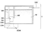
(インクタンクの全体構成)
図17は、本例のインクタンク2の分解斜視図である。インクタンク2は、内部にインク収納室180を備えた容器であり、その主体は、インク容器筐体110と蓋部材120とにより構成されている。インクタンク2の底部には、記録ヘッドにインクを供給するためのインク供給口130が形成され、また、インクタンク2の天井部には大気連通口110Aが形成されている。インクタンク2において、インク収納室180内を負圧に保つ必要がある場合には、負圧発生機構(不図示)を設けてもよい。
(Overall configuration of ink tank)
FIG. 17 is an exploded perspective view of the
インク容器筐体110は、例えばポリプロピレンにより形成されており、その内部にはインクを攪拌するための撹拌部材としての揺動部材300が収容され、そしてインク容器筐体110の開口部は蓋部材120によって封じられている。インク容器筐体110の内壁には、揺動部材300を支持するための突起部140が設けられ、インク供給口130にはメニスカス形成部材131が備えられている。メニスカス形成部材131は、ポリプロピレンの繊維材料から形成されて毛細管力を有する毛管部材、あるいは、毛管部材とフィルター部材とを組み合わせた吸収体である。フィルター部材の透過寸法は15〜30μm程度、材質はステンレス材料やポリプロピレンなどである。メニスカス形成部材131とインク容器筐体110の内部はインク流路によって連通されており、インク容器筐体110内のインク収納室180から記録ヘッドにインクが供給できるようになっている。メニスカス形成部材131内にはインクによるメニスカスが形成され、これにより、外部からの気泡がインク容器筐体110内に侵入しないようになっている。メニスカス形成部材131は、押え部材32によって外側から押されてタンクに保持されている。インク収納室180の天井部には大気連通口110Aが設けられており、記録ヘッドへの供給によってインク収納室180内のインクが消費されるにしたがって、インク収納室180内のインクの液面が下がるように構成されている。
The
(攪拌機構の構成)
図18は、揺動部材300の設置状態を説明するための斜視図、図19は、その揺動部材300の拡大斜視図である。
(Configuration of stirring mechanism)
FIG. 18 is a perspective view for explaining the installation state of the
揺動部材300の支持部301の両側は、インク容器筐体110の内壁に形成された突起部140に引っ掛かり、これにより揺動部材300が支持される。突起部140は、揺動部材300が揺動する際の支点となる。揺動部材300には、インク容器筐体110の重力方向の下側に位置する下側開口部302と、その上側に位置する上側開口部303と、が形成され、それらの開口部302,303の間に中空部304が形成されている。上側開口部303は、上下方向に延在する中空部304に対して鉛直方向斜めに開口している。このように揺動部材300は、内部が中空の中空部304となるように立体的に成形されている。
Both sides of the
本例の揺動部材300は、その下側開口部302の近辺に設けられた支持部301によって、突起部140に支持されている。そのため、図20(c)のように揺動部材300が揺動した際には、下側開口部302よりも上側開口部303の変位量が大きくなる。また、揺動部材300は、ステンレス材料によって形成されている。但し、揺動部材300の形成材料はこれに限られたものでなく、インク収納室180内に収容されたインクよりも比重が大きい材料であればよい。揺動部材300は、インク収納室180内にインクが充填された時に、開口部302,303および中空部304がインクに没する構成となっている。
The
(攪拌機構の動作および作用)
図20(a)から(c)は、第2の実施形態における揺動部材300の動作を説明するためのインクカートリッジ2の側断面図であり、図17のXX−XX線に沿う断面図である。
(Operation and action of stirring mechanism)
20A to 20C are side sectional views of the
図20(a)は、揺動部材300の第1の状態を示す。キャリッジM4001は記録媒体の記録幅の範囲において主走査方向(矢印X方向)往復移動するため、その移動方向が反転する際には、減速、停止、および反対方向への加速が行なわれる。その際、インクカートリッジ2には慣性力が働く。その慣性力が矢印X1方向に働く場合、つまりキャリッジM4001の移動方向が矢印X1方向からX2方向に反転する場合、揺動部材300は、図20(a)のように、支持部301を支点として矢印E1方向に回転する。このとき上側開口部303側は、突起部140が設けられているインク容器筐体110の内壁に接触する方向に変位する。ここでは、このように慣性力がX1方向に働いている状態を第1の状態としている。キャリッジM4001の移動方向が矢印X1方向からX2方向に反転した後、キャリッジM4001が矢印X2方向の等速移動するときには、慣性力は働かなくなり、揺動部材300は第1の状態のままに保たれる。
FIG. 20A shows a first state of the
図20(b)は、揺動部材300の第2の状態を示す。第2の状態は、第1の状態とは逆に、慣性力がX2方向に働く場合、つまりキャリッジM4001の移動方向が矢印X2方向からX1方向に反転する場合であり、揺動部材300は、図20(b)のように、支持部301を支点として矢印E2方向に回転する。このとき上側開口部303側は、蓋部材120に接触する方向に変位する。ここでは、このように慣性力がX2方向に働いている状態を第2の状態としている。キャリッジM4001の移動方向が矢印X2方向からX1方向に反転した後、キャリッジM4001が矢印X1方向の等速移動するときには、慣性力は働かなくなり、揺動部材300は第2の状態のままに保たれる。
FIG. 20B shows a second state of the
記録動作もしくはインクを撹拌する動作に伴って、キャリッジM4001が往復移動を繰り返すため、揺動部材300は、繰り返し図20(a),(b)の第1および第2の状態となって、インク収納室180内のインクを攪拌する。
Since the carriage M4001 repeats reciprocating movement in accordance with the recording operation or the ink agitating operation, the swinging
図20(c)は、揺動部材300が揺動するときの開口部302,303の変位方向、変位量、およびインクの流れを示す。
FIG. 20C shows the displacement direction, displacement amount, and ink flow of the
上述したように、揺動部材300の揺動に伴う上側開口部303の変位量X(303)は、下側開口部302の変位量X(302)よりも大きい。上側開口部303の少なくとも一部、下側開口部302、および中空部304が共にインクに没していれば、中空部304を通して、下側開口部302から上側開口部303に向かうインクの流れF1,F2,F3が生じる。このインクの流れを利用して、インク収納室180内のインクを攪拌することができる。
As described above, the displacement amount X (303) of the
本実施形態において、上側開口部303は、上下方向に延在する中空部304に対して鉛直方向斜めに開口する形状となっている。揺動部材300は、図21(a)のように、その上側開口部303の全てがインク収納室180内のインク90に没している必要はない。図21(b)および(c)のように、少なくとも上側開口部303の一部がインク90に没していれば、前述したような攪拌効果を発揮することができる。このことは、インク90の消費に伴ってインク収納室180内のインク90の液面が下がる構成のインク容器筐体10において、有用である。
In the present embodiment, the
また、揺動部材300の上側開口部303は、図22のように、揺動部材300の揺動方向に対面した面に、斜めに開口させてもよい。
Further, the
(第3の実施形態)
次に、本発明の第3の実施形態について説明する。
(Third embodiment)
Next, a third embodiment of the present invention will be described.
本実施形態におけるインクジェット記録装置M1001は、図23に示すように、シャフトM4002に沿って主走査方向(矢印X方向)に往復移動可能なキャリッジM4001に、記録ヘッドカートリッジH1002が着脱自在に搭載される。記録ヘッドカートリッジH1002は、サブタンク(液体収納容器)3と記録ヘッドH1000とを一体的に結合した構成となっている。図24のように、サブタンク3内には、前述した第2の実施形態のインクタンク1と同様に、揺動部材300が備えられている。サブタンク3内のインク90は、フィルター1303およびインク流路1304を通して、記録ヘッドH1000を構成する記録チップに供給され、その記録ヘッドH1000の吐出口から吐出される。
In the ink jet recording apparatus M1001 in this embodiment, as shown in FIG. 23, a recording head cartridge H1002 is detachably mounted on a carriage M4001 that can reciprocate in the main scanning direction (arrow X direction) along a shaft M4002. . The recording head cartridge H1002 has a configuration in which a sub tank (liquid storage container) 3 and a recording head H1000 are integrally coupled. As shown in FIG. 24, a
サブタンク3と、キャリッジM4001の外に設置されるメインタンク1311と、の間には、チューブ1301が接続されている。メインタンク1311にはインク90が収納されており、そのインク90は、ポンプ1302によってサブタンク3へ供給される。したがって、メインタンク1311内のインク90は、一旦、サブタンク3に入ってから、記録ヘッドH1000に供給されることになる。
A
画像の記録に際しては、前述した実施形態のシリアルスキャンタイプの記録装置と同様に、記録ヘッドH1000がキャリッジM4001と共に主走査方向に移動しつつインクを吐出する動作と、記録媒体を副走査方向に搬送する動作と、繰り返す。 When recording an image, the recording head H1000 discharges ink while moving in the main scanning direction together with the carriage M4001, and transports the recording medium in the sub-scanning direction, as in the serial scan type recording apparatus of the above-described embodiment. And repeat.
サブタンク3内のインク90は、前述した実施形態と同様に、記録装置の非使用時間が長期間続いた場合には、顔料インク中の顔料粒子がサブタンク3の下層部に沈降しやすくなる。前述した第2の実施形態と同様に、サブタンク3の内壁に揺動部材300が支持されているため、キャリッジM4001の往復移動(図24中紙面の表裏方向)に伴う慣性力によって、揺動部材300を揺動させることができる。この結果、前述した第2の実施形態と同様に、揺動部材の中空部にインク流を発生させて、サブタンク3内のインク90をまんべんなく攪拌することができる。
In the
本実施形態においても、上側開口部303の少なくとも一部がインク90に没していれば、攪拌効果を発揮することができる。このことは、本例のようにインク90の消費に伴ってインクタンク内のインク90の液面が下がるサブタンク3の構成において、有用である。
Also in this embodiment, if at least a part of the
(第4の実施形態)
次に、本発明の第4の実施形態について説明する。本実施形態における液体収納容器は、前述した図1から図3の記録装置に搭載可能なインクタンクとしての適用例である。
(Fourth embodiment)
Next, a fourth embodiment of the present invention will be described. The liquid container in the present embodiment is an application example as an ink tank that can be mounted in the recording apparatus of FIGS. 1 to 3 described above.
(インクタンク全体の構成)
図25は、インクタンク4の外観斜視図である。インクタンク4は、内部にインク収納室を備えた容器であり、主に、インク容器筐体401と蓋部材402から構成されている。インクタンク4の底部には、記録ヘッドH1000にインクを供給するためのインク供給口403が備えられている。
(Configuration of the entire ink tank)
FIG. 25 is an external perspective view of the
図26は、インクタンク4の分解斜視図である。インクタンク4のインク容器筐体401は、例えばポリプロピレンで形成されており、その内部には、インクを攪拌するための揺動部材500が収容される。インク容器筐体401の開口部は、蓋部材402によって封じられている。インク容器筐体401の内部は仕切壁413によって2つの空間に仕切られており、その仕切壁413の下側には、それら2つの空間を連通する連通部414が形成されている。この2つの空間の内、一方の空間は、インクが収容されるインク収納室411であり、連通部414を除いて密閉されている。また、他方の空間は負圧発生室412である。負圧発生室412に面する蓋部材402の部分には、インク消費に伴って大気を導入するための大気連通口417が形成されている。また、負圧発生室412に面するインク容器筐体401の部分には、記録ヘッドH1000にインクを供給するための供給口403が形成されている。供給口403には、インクを保持するためのメニスカス形成部材404が備えられている。メニスカス形成部材404内にはインクによるメニスカスが形成され、外部からの気泡がインク容器筐体401内に侵入しないようになっている。
FIG. 26 is an exploded perspective view of the
負圧発生室412内には、ポリプロピレンの繊維材料から形成されて毛管力を有する第1および第2の2つの負圧発生部材415および416が収納されている。負圧発生室内412内において、これらの負圧発生部材415および416は互いに圧接されて収納されている。負圧発生部材415および416は、種々の多孔質または繊維部材を含むことによってインクを吸収可能な吸収体であってもよい。第1の負圧発生部材415の毛管力をP1、第2の負圧発生部材416の毛管力をP2、メニスカス形成部材404の毛管力をP3とすると、これらの毛管力はP1<P2<P3の関係にある。
In the negative
このような構成において、負圧発生室412内のインクが記録ヘッドによって消費されると、大気連通口417から負圧発生室412に空気が導入され、その空気が連通部414を通してインク収納室411に入る。このようなインク収納室411へ空気の導入に代わって、連通部414を通して、インク収納室411から負圧発生室412内の負圧発生部材415、416にインクが充填される。このように、連通部414を通して、空気とインクが気液交換される。
In such a configuration, when ink in the negative
(攪拌機構の構成)
図27は、揺動部材500の設置状態を説明するための斜視図、図28は、その揺動部材500の拡大斜視図である。
(Configuration of stirring mechanism)
FIG. 27 is a perspective view for explaining an installation state of the
揺動部材500は、インク容器筐体401の重力方向の下側に位置する下側開口部502と、その上側に位置する上側開口部503と、が形成されている。それらの開口部502,503の間には、断面楕円形の筒状となるように中空部504が立体的に形成されている。また、下側開口部502近傍において、楕円形の長軸に当たる位置の2カ所には、凹形状の支持部501が設けられている。
The
本例における揺動部材500はステンレス材料によって形成され、その内側の中空部504には、インク中の泡が溜まらないように、例えば、サンドブラスト等の親水化処理が施されている。揺動部材500の形成材料は、これに限られたものではなく、またインク収納室411内に収容されたインクよりも比重が大きい材料が望ましい。また、中空部504の形状は楕円形に限らず、円形や角形であっても構わない。また、支持部501の形状は、凹形状であっても揺動部材500を貫通している形状であってもよく、さらに、支持部501の位置は、開口部502近傍における楕円形の長軸に当たる位置でなくても構わない。
The
図27に示すように、インク収納室411の内壁には固定部材408が設けられ、その固定部材408には突起部409が設けられている。突起部409と、揺動部材500の支持部501と、が嵌合することにより、支持部501は、揺動部材500が揺動する際の支点となる。揺動部材500は、支持部501を支点として揺動自在となる。本例の揺動部材500は、その下側開口部502の近辺の支持部501が支持されるため、揺動部材500が揺動した際には、上側開口部503の変位量が下側開口部502よりも大きくなり、その移動速度も速くなる。
As shown in FIG. 27, a fixing
(インクの充填方法)
インクをインクタンクに充填する方法について説明する。
(Ink filling method)
A method for filling the ink tank with ink will be described.
まずは、インクが揺動部材500に接する位置まで、インク収容室411内にインクを注入する。インクが揺動部材500に接した後は、インクをゆっくり注入し、親水化処理された揺動部材500の内壁に沿うような中空部504内へのインクの充填を先行させる。その後に、インク収容室411の壁面に沿うようなインク収容室411内へのインクの充填を行なう。インクの充填方法は、このような充填方法に限定されない。例えば、始めに、揺動部材500の下側開口部502をフィルムで塞ぎ、その中空部504内にインクを充填してから、上側開口部503をフィルムで塞ぐ。その後に、インクが充填された揺動部材500が位置するインク収容室411内に、インクを注入してから、下側開口部502のフィルムと上側開口部503のフィルムを破ることによって、インク収納室411内の全体にインクを充填させてもよい。インク収納室411内にインクが充填されると、揺動部材500の開口部502,503および中空部504はインクに没する。
First, ink is injected into the
このように、揺動部材500の中空部504内へのインクの充填と、インク収納室411内へのインクの充填と、を分けて行なうことにより、中空部504内に泡が溜まらないようにインクを充填することができる。
As described above, the ink filling into the
(撹拌機構の動作および作用)
図29(a)から(d)は、図2におけるキャリッジの動作を説明するための記録装置の要部の概略構成図である。図30(a)から(h)は、本例における揺動部材500の動作、および揺動部材500の中空部504内に生じるインク流の説明図であり、インクタンクの底部に沈降した濃い顔料成分のインクが撹拌される様子を表している。図30(a)から(h)は、図25のXXX−XXX線に沿う断面図に相当する。
(Operation and action of stirring mechanism)
FIGS. 29A to 29D are schematic configuration diagrams of the main part of the recording apparatus for explaining the operation of the carriage in FIG. FIGS. 30A to 30H are explanatory diagrams of the operation of the
まず、図29(a)から(d)を用いて、液体収容器としてのインクタンク4を装着したキャリッジM4001の動作について説明する。
First, the operation of the carriage M4001 equipped with the
キャリッジM4001は、図29(a)のようなホームポジションの位置から、記録装置M1000のシャーシに設置されたキャリッジシャフトM3020に沿って矢印X2方向に移動する(図29(b)参照)。そして、記録媒体の記録幅、もしくは、揺動部材500を動作させるために必要な距離だけ、キャリッジM4001を移動させて、それを図29(c)のように位置させる。そして、その位置からキャリッジM4001の移動方向を反転させて、それを矢印X1方向に移動させる(図29(d)参照)。そして、図29(a)の位置から、再び、キャリッジM4001の移動方向を反転させ、その後、その矢印X方向の往復移動を記録に必要な回数だけ反復する。キャリッジM4001は、その移動方向が反転する際に、減速、停止、および反対方向への加速が行なわれる。このように本例においては、記録のためのキャリッジM4001の往復移動に先立って、図29(b)から(d)のように、少なくとも1回はキャリッジM4001を往復移動させる。これにより、後述するように、記録動作に先立ってインクを攪拌することができる。
The carriage M4001 moves from the home position as shown in FIG. 29A in the direction of the arrow X2 along the carriage shaft M3020 installed in the chassis of the recording apparatus M1000 (see FIG. 29B). Then, the carriage M4001 is moved by a recording width of the recording medium or a distance necessary to operate the swinging
次に、図30(a)から(h)を用いて、キャリッジM4001の往復移動に伴うインクタンク4内の揺動部材500の動作について説明する。これらの図に示すインク収容室411は、その内部がインクで満たされている状態にある。
Next, the operation of the
図30(a)は、キャリッジM4001が図29(a)のようにホームポジションに静置され、インク収納室411内の揺動部材500は、その上側開口部503側がインク収納室411の内壁に接して静置している状態を示す。この状態は、キャリッジM4001が図29(a)の位置から動き出してから、図29(b)のようにX2方向に等速移動するときまで保たれたままである。
30A, the carriage M4001 is stationary at the home position as shown in FIG. 29A, and the
図30(b)から(e)は、キャリッジM4001が図29(c)の位置に到達してから、その移動方向がX2方向からX1方向に反転した時、もしくは図29(d)のように、キャリッジM4001が移動方向の反転後にX1方向に移動している時の状態を示す。キャリッジM4001の移動方向が反転する際、インクタンク4には慣性力が働く。その慣性力が矢印X2方向に働く場合、つまりキャリッジM4001の移動方向が矢印X2方向からX1方向に反転する場合、揺動部材500は、図30(b)から(e)に示す順に、支持部501を支点として矢印S2方向に揺動する。そして、図30(e)に示すように、揺動部材500の上側開口部503側がインク収納室411の反対側の内壁(図30(a)において接する内壁とは反対側の内壁)に接することにより、その揺動部材500のS2方向への揺動が停止する。揺動部材500は、キャリッジM4001が図29(c)の位置から動き出してから、図29(d)のようにX2方向に等速移動するまでは、図30(e)に示す状態に保たれたままである。
30B to 30E, when the carriage M4001 reaches the position of FIG. 29C and the movement direction is reversed from the X2 direction to the X1 direction, or as shown in FIG. 29D. The state when the carriage M4001 is moving in the X1 direction after reversing the moving direction is shown. When the moving direction of the carriage M4001 is reversed, an inertial force acts on the
図30(f),(g)は、キャリッジM4001がX1方向に移動して図29(a)の位置に到達してからX2方向に反転した時、もしくは、図29(b)に示すように、キャリッジM4001の移動方向が反転してからX2方向に移動している時の状態を示す。キャリッジM4001の移動方向が反転する時に生じる慣性力が矢印X1方向に働く場合、揺動部材500は、図30(f),(g)に示す順に、支持部501を支点として矢印S1方向に揺動する。その後、キャリッジM4001が再びX1方向に移動することにより、図30(h)に示すように、揺動部材500がS2方向に揺動する。
30F and 30G show the case where the carriage M4001 moves in the X1 direction and reaches the position in FIG. 29A and then reverses in the X2 direction, or as shown in FIG. 29B. The state when the carriage M4001 moves in the X2 direction after the movement direction is reversed is shown. When the inertia force generated when the moving direction of the carriage M4001 is reversed acts in the arrow X1 direction, the
キャリッジM4001が往復移動を繰り返す間、揺動部材500は、以上のような往復移動を繰り返す。
While the carriage M4001 repeats reciprocating movement, the swinging
次に、図30(a)から(h)を用い、揺動部材500の往復移動に伴って揺動部材500の中空部504内に生じるインク流、およびインクが撹拌される様子について説明する。
Next, with reference to FIGS. 30A to 30H, the ink flow generated in the
揺動部材500がS2方向に揺動し始めると、その揺動部材500が揺動したことにより生じる遠心力によって、図30(b)に示すように、中空部504内に存在するインクには、上側開口部503から流出する流れT2が生じる。それと同時に、下側開口部502近傍のインクタンク底部に存在しているインクには、中空部504に流入する流れT1が生じる。揺動部材500の揺動が継続されると、中空部504内のインクに作用する遠心力により、そのインクは、図30(b)から(d)中のように、中空部504内を流れて上側開口部503から流出する。
When the swinging
図30(e)のように、揺動部材500のS2方向への揺動が停止すると、中空部504内のインクには、揺動部材500の揺動の停止により生じる慣性力が作用し、中空部504内のインクの流れはさらに加速される。中空部504を経由したインクは、上側開口部503から流出された後、図30(f),(g)に示すような流れT3となって、顔料成分の薄いインク中に拡散される。また、インク収納室411のインクは、その内壁によって跳ね返るインクの流れT4によってさらに撹拌される。
As shown in FIG. 30E, when the swinging of the swinging
上側開口部503から流出された顔料成分の濃いインクは、T2、T3、T4の流れおよび重力により、揺動部材500が設置されている高さにまで降りてくる。そして図30(h)に示すように、揺動部材100の揺動に伴って、その外壁とインク収納室411の内壁との相対的な近接および離間変位によって、それらの間に機械的な流れT5が生じる。その流れT5によって、インク収納室411内のインクはさらに撹拌される。
The dark pigment component ink that has flowed out of the
以上のような動作を1回もしくは複数回実施することにより、インク収納室411内のインクは、T1からT5の流れにより下層部から上層部にまで持ち上げられて撹拌される。その結果、インク収納室411の上層部のインクを含めて、インク収納室411内全体をまんべんなく撹拌することができる。
By performing the above-described operation once or a plurality of times, the ink in the
揺動部材500の揺動は連続的に実施することが望ましく、その連続的な揺動により、インク収納室411内の上部に向かってインクを巻き上げるための推進力を高めることができる。つまり、揺動部材500の中空部504内のインクに流れT2を生じさせるポンピング作用を高めることができる。
The swinging of the swinging
また本例では、揺動部材500の揺動方向を反転させながら撹拌を行った。しかし、その揺動方向は必ずしも反転する必要は無い。慣性力によって、インク収納室の底部に位置する顔料粒子を揺動部材の中空部を経由して容器上部へ巻き上げるための充分な推進力が加えられればよく、揺動部材の一方向の揺動の後、その揺動部材が停止しても構わない。また、インク収容室411内のインクが減少して液面が下がっても、揺動部材500の中空部504がインクに没している限り、上述したようなインクの撹拌効果を得ることができる。
In this example, stirring was performed while inverting the swing direction of the
また、揺動部材500が図30(a),(f),(h)のように垂直に立っている状態から、図30(a),(e),(g)のように倒れきるまでの揺動の角度は、キャリッジの移動条件や揺動部材500の形態などを考慮して設定する必要がある。その揺動の角度が大きくて、例えば90度に近かった場合には、揺動部材500は、倒れきったまま揺動できなくなるおそれがある。したがって、キャリッジおよびインクタンク4の往復移動により、揺動部材500が往復移動できるように、揺動部材500の揺動の角度も考慮する必要がある。揺動部材を揺動させるためには、記録媒体への記録動作に伴うキャリッジの動きを利用してもよく、または、記録動作とは別に、インクタンク内のインクを撹拌するための攪拌動作に伴うキャリッジの動きを利用してもよい。記録装置は、そのような攪拌動作を実施するための撹拌モードを備えてもよい。この場合、記録ヘッドからのインクの吐出が停止した時間を記録装置側にてカウントし、そのカウントした時間がある一定時間を超えた場合に、記録装置が撹拌モードとなるようにしてもよい。その撹拌モードにおいては、インクタンクを搭載したキャリッジがX方向に移動される。キャリッジの移動幅や移動速度は、そのカウントした時間に応じて任意に設定することができる。また、記録装置による記録前など特定のタイミングを設定し、そのタイミングにて撹拌モードになっても構わない。
Also, from the state where the swinging
(第5の実施形態)
次に、本発明の第5の実施形態について説明する。本実施形態における液体収納容器は、前述した図1から図3の記録装置に搭載可能なインクタンクとしての適用例である。
(Fifth embodiment)
Next, a fifth embodiment of the present invention will be described. The liquid container in the present embodiment is an application example as an ink tank that can be mounted in the recording apparatus of FIGS. 1 to 3 described above.
(インクタンク全体の構成)
図31は、本実施形態におけるインクタンク6の分解斜視図である。図32は、図31における揺動部材の設置状態を説明するための要部の斜視図である。インク容器筐体601は、例えばポリプロピレンで形成されており、その開口部は、蓋部材602によって封じられる。インク供給口610を形成するインク容器筐体601の部位には、押え部材605によって、メニスカス形成部材604が外側から押されて止められている。
(Configuration of the entire ink tank)
FIG. 31 is an exploded perspective view of the
メニスカス形成部材604と、インク容器筐体601の内部および押さえ部材605の内部と、の間は、インク流路によって連通されている。これにより、インク容器筐体601内のインク収納室611から、記録ヘッドH1000(図3参照)にインクが供給できるようになっている。メニスカス形成部材604内にインクによるメニスカスが形成されることにより、外部からの気泡がインク収納室611内に侵入しないようになっている。
The
蓋部材602には、インク収納室611内に大気を流入させるための大気連通口606が形成されており、インク収納室611は、この大気連通口606以外の部分では外気と遮断されている。細管607は中空であり、その一端は大気連通口606に連通され、その他端は、インク収納室611内の重力方向下側の底部近傍においてインク収納室611内に開口する。このような構成により、インク収納室611内のインクの消費に伴って、細管607の他端からインク収納室611内に空気が流入する。このとき、インクの消費に伴うインク収納室611の減圧と、細管607内のインクのメニスカス力と、によって、インク収納室611内が負圧状態になる。
The
本例における揺動部材500は、下側開口部502、上側開口部503、および円筒形の中空部504が形成されている。下側開口部502の近傍の2箇所には、凹形状の支持部501が設けられている。前述した第4の実施形態と同様に、この支持部501が、インク収納室611の内壁に設けられた固定部材608の突起部609に嵌合することにより、図32に示すように揺動可能に支持される。支持部501は、揺動部材500が揺動する際の支点となる。
In the
(実験結果)
次に、本実施形態の効果を検証するために、本発明者らが実験した結果について説明する。
(Experimental result)
Next, in order to verify the effect of this embodiment, the results of experiments conducted by the inventors will be described.
本実験において用いたインクタンクにおいて、そのインク収納室は、揺動部材の揺動方向の内寸が30mm、揺動方向と直交する方向の内寸が90mm、高さ方向の内寸が60mmである。揺動部材は、厚さ0.5mmのステンレス材料(比重約8.0)を円筒状に形成したものであり、その内径は10mm、高さが20mmである。インク収納室内はインク(比重約1.0)で満たされており、そのインクの下層部は色材が沈降した状態であった。 In the ink tank used in this experiment, the ink storage chamber has an inner dimension in the swing direction of the swing member of 30 mm, an inner dimension in the direction orthogonal to the swing direction of 90 mm, and an inner dimension in the height direction of 60 mm. is there. The swing member is made of a stainless material (specific gravity of about 8.0) having a thickness of 0.5 mm in a cylindrical shape, and has an inner diameter of 10 mm and a height of 20 mm. The ink storage chamber was filled with ink (specific gravity of about 1.0), and the color material had settled in the lower layer portion of the ink.
このようなインクタンクをインクジェット記録装置のキャリッジに設置し、そのキャリッジを移動距離2インチ、移動速度36インチ/秒の速度で往復移動させた。その結果、前述した各実施形態と同様に、揺動部材が揺動することにより、インク収納室の底部に沈降していた色材は、揺動部材の中空部に案内されて、インクの下層部から上層部に向けて流れた。そして、キャリッジを15往復させて、その慣性力により揺動部材を15往復させることにより、インク収納室内のインク全体の色材が撹拌されることが分かった。 Such an ink tank was installed on the carriage of the ink jet recording apparatus, and the carriage was reciprocated at a moving distance of 2 inches and a moving speed of 36 inches / second. As a result, as in the above-described embodiments, when the swinging member swings, the color material that has settled at the bottom of the ink storage chamber is guided to the hollow portion of the swinging member, and the lower layer of the ink Flowed from the upper part to the upper part. Then, it was found that the color material of the entire ink in the ink storage chamber is agitated by reciprocating the carriage 15 times and reciprocating the swing member 15 times by the inertial force.
このように本実施形態においても、揺動部材の揺動により、インク収納室のインクの下層部から上層部に向かってインクの流れを生じさせ、そのインクの流れにより、濃度の濃いインクと薄いインクとを対流させて攪拌することができる。つまり、揺動部材500を動作させることにより、顔料成分の濃いインクを下層部から上層部にまで持ち上げて、インク収納室611全体のインクをまんべんなく効率的に撹拌することができる。この結果、カートリッジ形態のインクタンク(インクカートリッジ)の使用初期と使用後期において、記録画像に濃度差が生じることを防止し、また、複数のカラーインクを用いた場合におけるカラーバランスの崩れを防止することができる。
As described above, also in the present embodiment, the swing of the swing member causes an ink flow from the lower layer portion to the upper layer portion of the ink in the ink storage chamber, and the ink flow causes the darker ink to be thinner. The ink can be convected and stirred. In other words, by operating the
ところで、インク容器筐体601のインク供給口610近傍は、その下部にメニスカス形成部材604を有することもあって、比較的複雑な形状となりやすい。そのため、インク収納室611内のインク供給口610近傍に位置するインクは、インク収納室611内の他の部位に位置するインクよりも撹拌され難い傾向がある。したがって、揺動部材500は、図32に示すようにインク供給口610に対向する位置に設置することが望ましい。
By the way, the vicinity of the
(攪拌機構の構成の変形例)
図33は、インクの攪拌機構の変形例を説明するための分解斜視図である。図34は、図33における揺動部材の設置状態を説明するための要部の斜視図である。図35は、図33におけるインク容器筐体の横断面図である。
(Modification of the configuration of the stirring mechanism)
FIG. 33 is an exploded perspective view for explaining a modification of the ink stirring mechanism. FIG. 34 is a perspective view of a main part for explaining the installation state of the swinging member in FIG. 35 is a cross-sectional view of the ink container housing in FIG.
本例の揺動部材500は、図35に示すように、断面が楕円形状の中空部504の2箇所に穴を貫通されており、その穴によって支持部501が形成されている。これらの支持部501には、その内径より小さい外径を有する支持軸515が通され、その後、その支持軸515の2箇所が互いに異なる方向に折り曲げられることによって、屈曲部516が形成される。揺動部材500を貫通した状態の支持軸515の両端部は、インク容器筐体601の内部に設けられたガイド620を通して、インク容器筐体601の底部近辺にまで誘導される。そして図34のように、支持軸515の両端部はガイド620の底部(下端部)にて支持される。支持軸515の両端部は、係合手段などによって、ガイド620の底部(下端部)に積極的に固定してもよい。
As shown in FIG. 35, the
揺動部材500は、支持部501および支持軸515を支点として揺動することにより、前述した揺動部材500と同様に、インク収納室611内のインクを下層部から上層部にまで持ち上げて効率よく攪拌することができる。
The
(第6の実施例)
図36は、本発明の第6の実施形態におけるインクタンク1の外観斜視図である。先述した実施形態と共通する部分については、同じ番号で示して説明を省略する。図37は、そのインクタンク1の分解斜視図である。
(Sixth embodiment)
FIG. 36 is an external perspective view of the
(攪拌機構の構成)
図38は、揺動部材100の設置状態を説明するための斜視図である。揺動部材100の支持部101の両側は、インク容器筐体10の内壁に形成された突起部40に引っ掛けられ、これにより揺動部材100は、ばね部材50と接触しないように支持される。突起部40は、揺動部材100が回動する際の支点となる。揺動部材100は、ステンレス材料によって形成されている。突起部40の頭部は、揺動部材100の支持部101が外れないように大径に形成されている。突起部40は、揺動部材100の回動支点となると共に、その突起部40の軸線方向における揺動部材100のスライドをも許容する。揺動部材100には、インク容器筐体10の重力方向の下側に位置する下側開口部102と、その上側に位置する上側開口部103と、が形成され、それらの開口部102,103の間に中空部104が形成される。このように揺動部材100は、内部が中空部104となるように立体的に成形されている。
(Configuration of stirring mechanism)
FIG. 38 is a perspective view for explaining an installed state of the
このように本例の揺動部材100は、上側開口部103の近辺に設けられた支持部101が突起部40に支持される。そのため、揺動部材100が回動した際には、上側開口部103よりも下側開口部102の変位量が大きくなる。
As described above, in the
本例のインクタンク4においては、揺動部材100を動作させることにより、後述する第7の実施形態と同様に、中空部104を通して、顔料成分の薄いインクが上層部から下層部に向かって流れる。さらに、揺動部材100の外壁とインク収納室80の内壁との近接および離間変位によって、インクの流れが生じる。これらのインクの流れの組み合わせにより、インク収納室80内のインク全体を撹拌することができる。
In the
(第7の実施形態)
図39は、本発明の第7の実施形態におけるインクタンク4の分解斜視図である。本例におけるインクタンク4には、前述した第4の実施形態におけるインクタンク4と同様に、インクを直接的に収容するインク収納室411と、負圧発生部材を収容する負圧発生室412と、が形成されている。インク収納室411の内部には、インクを攪拌するための揺動部材500が収容されている。図40は、揺動部材500の設置状態を説明するための斜視図、図41は、その揺動部材500の拡大斜視図である。
(Seventh embodiment)
FIG. 39 is an exploded perspective view of the
本例の揺動部材500は、インクタンク4の重力方向の下側に位置する下側開口部502と、その上側に位置する上側開口部503と、が形成されている。それらの開口部の間には、断面が楕円形の中空部504が形成されている。揺動部材500は、インク収納室411内にインクが充填されることにより、その開口部502,503および中空部504がインクに没するようになっている。
The
揺動部材500における上側開口部503の近傍において、楕円形の長軸に当たる位置の2箇所には、凹状の支持部501が設けられている。支持部501の形状は、揺動部材500を貫通する穴形状であってもよく、また、その位置は、本例のように楕円系の長軸に当たる位置でなくても構わない。
In the vicinity of the
蓋部材402には、インク収納室411に向けて延在する固定部材408が設けられている。図40のように、固定部材408の下端部に設けられた突起部409が揺動部材500の支持部501に嵌合することにより、揺動部材500が揺動自在に支持される。突起部409は、揺動部材500が回動する際の支点となる。本例においては、揺動部材500の上側開口部503の近辺が支持部501に支持されるため、第6の実施形態と同様に、揺動部材500が回動した際には、上側開口部503よりも下側開口部502の変位量が大きくなる。
The
次に、図29(a)から(d)のような記録装置のキャリッジM4001に本例のインクタンク4を搭載して、そのキャリッジを往復移動させたときの揺動部材400の動作を図42(a)から(e)を用いて説明する。
Next, the operation of the swing member 400 when the
図42(a)は、キャリッジM4001が図29(a)に示すホームポジションに静置されて、インク収納室411内の揺動部材500が支持部501を支点として重力方向下方に垂れ下がる状態を示す。
FIG. 42A shows a state where the carriage M4001 is stationary at the home position shown in FIG. 29A and the swinging
キャリッジM4001が図29(a)の位置から、(b)のようにX2方向に動き出したとき、図42(b)に示すように、慣性力の働きにより揺動部材500が矢印S1方向に揺動する。そして、その慣性力がインクの抵抗や重力の作用により揺動部材500に働かなくなると、図42(c)に示すように、揺動部材500は重力によってS2方向に向かって揺動する。
When the carriage M4001 starts to move in the X2 direction as shown in FIG. 29B from the position shown in FIG. 29A, the swinging
そして、図29(c)の位置においてキャリッジの移動方向がX2方向からX1方向へ反転したときに、図42(d)に示すように、揺動部材500に矢印X2方向の慣性力が働いて、その揺動部材500が矢印S2方向に揺動する。そして揺動部材500は、図42(d)に示すようにインク収納室411の内壁に接した後、その接したときの反力および重力の作用によってS1方向に戻される。そのように揺動部材500がS1方向に戻されている間に、図29(a)の位置においてキャリッジM4001の移動方向がX2方向からX1方向へ反転すると、揺動部材500には、さらに矢印X1方向に慣性力が働く。その慣性力により、揺動部材500は、図42(e)に示すように矢印S1方向に揺動する。
When the carriage movement direction is reversed from the X2 direction to the X1 direction at the position shown in FIG. 29C, the inertial force in the arrow X2 direction is applied to the
このように、キャリッジM4001が図29(a)から(d)の移動を連続的に繰り返すことにより、揺動部材500は図42(d)、(e)の揺動を繰り返す。本例では、揺動部材が重力と反力によりS1方向に戻る間に、キャリッジが反転を繰り返すため、比較的小さい慣性力によって揺動部材を揺動させることができる。
As described above, the carriage M4001 continuously repeats the movement from FIG. 29A to FIG. 29D, whereby the
次に、図42(a)から(e)を用いて、インク収容室411の底部に沈降した顔料成分の濃いインクが撹拌される様子について説明する。
Next, with reference to FIGS. 42A to 42E, how the dark pigment component ink that has settled at the bottom of the
揺動部材500がS1方向に揺動し始めると、その回動により生じる遠心力によって、揺動部材500の中空部504内に存在するインクは、図42(b)中の矢印T2のように、下側開口部502から放出される。それと同時に、上側開口部503の近傍の顔料成分の薄いインクは、矢印T1のように中空部104内に流入する。
When the oscillating
そして、揺動部材500の揺動が繰り返されると、中空部504内のインクに作用する遠心力により、顔料成分の薄いインクは、図42(d)に示すように、上側開口部503から中空部504内に流入して、下側開口部502から矢印T2方向に放出される。また、図42(d),(e)のように、揺動部材500のS1方向およびS2方向の揺動が停止したときには、中空部504内のインクに慣性力が働いて、そのインクの流れがさらに加速される。
When the swinging of the swinging
顔料成分の薄いインクは、下側開口部502から放出された後、図42(d),(e)中の矢印T3のように顔料成分の濃いインク中に拡散される。また、インク収納室411の内壁からの跳ね返りにより生じる流れT4によって、顔料成分の濃いインクがさらに撹拌される。また、図42(b)から図42(e)に示すように、揺動部材500が揺動している間は、中空部504内に下向きのインクの流れが生じる。また、それと同時に、揺動部材500の外壁とインク収納室411の内壁との相対的な近接および離間変位によって、インクの流れT5が生じる。これらの流れによって、インク収納室411内のインクはさらに撹拌される。
After the ink having a thin pigment component is discharged from the
このように、揺動部材500を揺動させるための動作を1回もしくは複数回実施することにより、インク収納室411内のインクは、T1からT5のインクの流れにより、インク収納室411内のインク全体をまんべんなく撹拌することができる。すなわち、揺動部材の鉛直方向中央部よりも上側に揺動支点を位置させることにより、重力方向上方に位置する開口部から導入したインクを重力方向下方に位置する開口部から導出することができる。これにより、中空部を経由して、重力方向の上方から下方に向かってインクを案内して攪拌することができる。このような撹拌の効果は、揺動部材500の内径、周囲長、表面積、長さ、比重、移動速度、移動距離、およびインクの粘度や接触角等のパラメータにより差が生じる。しかしながら、このようなパラメータは、顔料成分の薄いインクが揺動部材の中空部を経由して下方に流れるために充分な推進力が得られるのであれば、どのように設定してもよい。タンク内のインクに作用する遠心力、および慣性力によって、このような推進力が発生するように、揺動部材500を揺動させることができればよい。
As described above, by performing the operation for swinging the
(第8の実施形態)
図43は、本発明の第8の実施形態におけるインクタンク6の分解斜視図である。図44は、図43における揺動部材500の設置状態を説明するための要部の斜視図である。
(Eighth embodiment)
FIG. 43 is an exploded perspective view of the
本例におけるインクタンク6には、前述した第5の実施形態におけるインクタンク6と同様に、インクを収容するインク収納室611が形成されている。また、本例における揺動部材500には、前述した第7の実施形態における揺動部材500と同様に、下側開口部502、上側開口部503、中空部504、および支持部501が形成されている。
In the
蓋部材602には、インク収納室611に向けて延在する固定部材608が設けられている。図44のように、固定部材608の下端部に設けられた突起部609が揺動部材500の支持部501に嵌合することにより、揺動部材500が揺動自在に支持される。突起部609は、揺動部材500が回動する際の支点となる。本例においては、揺動部材500の上側開口部503の近辺が支持部501に支持されるため、前述した第6および第7の実施形態と同様に、揺動部材500が回動した際には、上側開口部503よりも下側開口部502の変位量が大きくなる。
The
インク容器筐体601のインク供給口610近傍は、その下部にメニスカス形成部材604を有することもあって、比較的複雑な形状となりやすい。そのため、インク収納室611内のインク供給口610近傍に位置するインクは、インク収納室611内の他の部位に位置するインクよりも撹拌され難い傾向がある。したがって、揺動部材500は、図44に示すようにインク供給口610に対向する位置に設置することが望ましい。
The vicinity of the
本例のインクタンク6においても、第6および第7の実施形態と同様に、揺動部材500を動作させることにより、中空部504を経由して、顔料成分の薄いインクをインクタンク内のインクの下層部に吹き下ろすことができる。さらに、揺動部材500の外壁とインク収納室の内壁との近接および離間によって、インクの流れを生じさせることができる。このように揺動部材の内外に生じる2つの流れの組み合わせにより、インク収納室内部のインク全体を撹拌することができる。
Also in the
ところで、使用する顔料インク中の顔料の種類によっては、攪拌時のインクの流れによって、顔料がインク収納室の底部の角に溜まって凝集するおそれがある。このように顔料が凝集した場合に、インクの攪拌動作を行っても顔料が攪拌され難くなる。インク収納室の底部の角部に顔料を凝集させないためには、図45に示すように、少なくともインク収納室611の底部の角に、インク収納室611の内部に向かって傾斜する平面状や円弧面状の面部220を形成することが望ましい。
By the way, depending on the kind of pigment in the pigment ink to be used, there is a possibility that the pigment may accumulate and aggregate at the bottom corner of the ink storage chamber due to the flow of ink during stirring. In this way, when the pigments are aggregated, the pigments are not easily stirred even if the ink stirring operation is performed. In order to prevent the pigment from aggregating at the corners of the bottom of the ink storage chamber, as shown in FIG. 45, at least at the corner of the bottom of the
(第9の実施形態)
図46は、本発明の第9の実施形態におけるインクタンク4の分解斜視図である。本例におけるインクタンク4には、前述した第4および第7の実施形態におけるインクタンク4と同様に、インクを直接的に収容するインク収納室411と、負圧発生部材を収容する負圧発生室412と、が形成されている。インク収納室411の内部には、インクを攪拌するための揺動部材500が収容されている。図47は、揺動部材500の設置状態を説明するための斜視図、図48は、インク容器本体401の横断面図である。
(Ninth embodiment)
FIG. 46 is an exploded perspective view of the
本例の揺動部材500は、図48に示すように、断面が楕円形状の中空部504の2箇所に穴を貫通されており、その穴によって支持部501が形成されている。これらの支持部501には、その内径より小さい外径を有する支持軸116が通され、その後、その支持軸116の2箇所が互いに異なる方向に折り曲げられることによって、屈曲部111が形成される。揺動部材500を貫通した状態の支持軸116の両端部は、インク容器筐体401の内部に設けられたガイド117を通して、インク容器筐体401の底部近辺にまで誘導される。そして図47のように、支持軸116の両端部はガイド117の底部(下端部)にて支持される。支持軸116の両端部は、係合手段などによって、ガイド117の底部(下端部)に積極的に固定してもよい。
As shown in FIG. 48, the
本例のインクタンク4においても、第6から第8の実施形態と同様に、揺動部材500を動作させることにより、中空部504を経由して、顔料成分の薄いインクをインクタンク内のインクの下層部に吹き下ろすことができる。さらに、揺動部材500の外壁とインク収納室の内壁との近接および離間によって、インクの流れを生じさせることができる。このように揺動部材の内外に生じる2つの流れの組み合わせにより、インク収納室内部のインク全体を撹拌することができる。
Also in the
(第10の実施形態)
図49は、本発明の第10の実施形態を説明するための図であり、前述した図23のサブタンク3内に、図40と同様の揺動部材500を備えた構成となっている。
(Tenth embodiment)
FIG. 49 is a view for explaining the tenth embodiment of the present invention. In the
サブタンク3内のインク90は、フィルター1303およびインク流路1304を通して、記録ヘッドH1000を構成する記録チップに供給され、その記録ヘッドH1000の吐出口から吐出される。サブタンク3と、キャリッジM4001の外に設置されるメインタンク1311と、の間には、チューブ1301が接続されている。メインタンク1311にはインク90が収納されており、そのインク90は、ポンプ1302によってサブタンク3へ供給される。したがって、メインタンク1311内のインク90は、一旦、サブタンク3に入ってから、記録ヘッドH1000に供給される。
The
画像の記録に際しては、シリアルスキャンタイプの記録装置と同様に、記録ヘッドH1000がキャリッジM4001と共に主走査方向に移動しつつインクを吐出する動作と、記録媒体を副走査方向に搬送する動作と、を繰り返す。 When recording an image, as in the serial scan type recording apparatus, the recording head H1000 performs an operation of ejecting ink while moving in the main scanning direction together with the carriage M4001, and an operation of transporting the recording medium in the sub scanning direction. repeat.
サブタンク3の上部には下方に延在する突起部408が設けられており、前述した図40と同様に、その突起部408によって揺動部材500の上側部分が揺動自在に支持されている。したがって、キャリッジM4001の往復移動(X)に伴う慣性力によって、揺動部材500を揺動(回動)させることができる。
A
この結果、第6から第9の実施形態と同様に、揺動部材500を動作させることにより、中空部504を経由して、顔料成分の薄いインクをインクタンク内のインクの下層部に吹き下ろすことができる。さらに、揺動部材500の外壁とサブタンク3の内壁との近接および離間によって、インクの流れを生じさせることができる。このように揺動部材の内外に生じる2つの流れの組み合わせにより、サブタンク3内部のインク全体を撹拌することができる。
As a result, similarly to the sixth to ninth embodiments, by operating the
(他の実施形態)
本発明の液体収納容器は、その内部に備えた揺動部材の中空部に、液体を攪拌するための液体の流れを容器底部から上部に向かって、または容器上部から底部に向かって積極的に生じさせることができればよい。その液体の流れの方向は、液体の収納空間の形状、液体の種類などに応じて最適に設定することができる。また、その液体の流れは、少なくとも2つの開口部(第1開口部および第2開口部)と、その間の中空部を通して生じればよい。
(Other embodiments)
The liquid storage container according to the present invention positively moves the liquid flow for stirring the liquid from the bottom to the top of the container or from the top to the bottom of the container. It only needs to be generated. The direction of the liquid flow can be optimally set according to the shape of the liquid storage space, the type of liquid, and the like. Further, the liquid flow may be generated through at least two openings (first opening and second opening) and a hollow portion therebetween.
したがって、揺動部材における中空部および開口部の位置、形状、および数などは任意である。 Therefore, the position, shape, number, and the like of the hollow part and the opening part in the swing member are arbitrary.
また、揺動部材の中空部を通る液体の流れを生じさせるための流動手段の構成も任意であり、前述したように揺動部材の移動を伴う構成のみに特定されない。例えば、揺動部材を固定してもよい。この場合には、揺動部材を動かす代わりに、前述した図16の実施形態のようにインクタンクの外部からインクの流れZを導入し、その流れZによって、少なくとも揺動部材における2つの開口部付近の液体に圧力差を生じさせてもよい。また、揺動部材を移動可能とする場合、その移動形態は特に限定されず、特定の支点を中心として揺動可能(回動可能)に備える他、所定の軌跡に沿って往復移動可能に備えたり、あるいは液体収納容器の特定の面に沿って自由に移動する構成としてもよい。要は、揺動部材の移動を伴って、その中空部に、容器底部から上部へ向かう液体の流れ、あるいは容器上部から底部へ向かう液体の流れが生じればよい。 Further, the configuration of the flow means for generating the liquid flow through the hollow portion of the swing member is also arbitrary, and is not limited to only the configuration involving the movement of the swing member as described above. For example, the swing member may be fixed. In this case, instead of moving the swing member, an ink flow Z is introduced from the outside of the ink tank as in the above-described embodiment of FIG. 16, and at least two openings in the swing member are generated by the flow Z. A pressure difference may be generated in the nearby liquid. Further, when the swinging member is movable, the moving form is not particularly limited, and the swinging member is provided so as to be swingable (rotatable) around a specific fulcrum and to be capable of reciprocating along a predetermined locus. Or it is good also as a structure which moves freely along the specific surface of a liquid container. In short, it is only necessary that a liquid flow from the bottom of the container to the top or a liquid flow from the top to the bottom of the container is generated in the hollow portion with the movement of the swing member.
液体の流れを生じさせるための流動手段は、開口部と液体とを相対移動させたときに、ベルヌーイの定理により開口部付近に生じる液体の負圧を利用する他、液体の遠心力や慣性力などを利用することができる。すなわち、揺動部材の揺動に伴う中空部内の液体の遠心力を利用したり、揺動部材の移動停止時における中空部の内または外の液体の慣性力などを利用することができる。また、前述した図16の実施形態のようにインクの流れZを導入する他、外部から機械的な運動エネルギや磁気エネルギなどを導入し、それらを駆動力として揺動部材を移動させてもよい。 The flow means for generating the flow of the liquid uses the negative pressure of the liquid generated in the vicinity of the opening by Bernoulli's theorem when the opening and the liquid are moved relative to each other, as well as the centrifugal force and inertial force of the liquid. Etc. can be used. That is, it is possible to use the centrifugal force of the liquid in the hollow portion accompanying the swing of the swing member, or to use the inertial force of the liquid inside or outside the hollow portion when the swing member stops moving. Further, in addition to introducing the ink flow Z as in the embodiment of FIG. 16 described above, mechanical kinetic energy, magnetic energy, or the like may be introduced from the outside, and the swing member may be moved using these as driving forces. .
揺動部材の中空部内における液体の流れと、揺動部材の動きによって液体が機械的に攪拌されるときの液体の動きと、を組み合わせることにより、より効率よく液体を攪拌することができる。 By combining the flow of the liquid in the hollow portion of the rocking member and the movement of the liquid when the liquid is mechanically stirred by the movement of the rocking member, the liquid can be stirred more efficiently.
前述した実施形態においては、本発明における液体収納容器の適用例として、いわゆるシリアルスキャンタイプのインクジェット記録装置に搭載可能なインクタンクを示した。しかしながら、本発明はインクタンクのみに適応されるものではない。例えば、液体を案内する中空部を備えた揺動部材を有する液体収納容器を載置台に搭載し、その載置台を往復移動させることにより、揺動部材を揺動させて液体を撹拌する構成にも適用可能である。また、液体収納容器の移動は往復移動のみに限定されず、例えば、ある方向に移動した後、一旦停止してから再度同一方向に移動させることによっても、揺動部材を揺動させて液体を撹拌することが可能である。 In the embodiment described above, an ink tank that can be mounted on a so-called serial scan type ink jet recording apparatus has been shown as an application example of the liquid storage container in the present invention. However, the present invention is not only applicable to ink tanks. For example, a liquid storage container having a swinging member having a hollow portion for guiding liquid is mounted on a mounting table, and the mounting table is reciprocated to swing the swinging member to stir the liquid. Is also applicable. Further, the movement of the liquid container is not limited to reciprocal movement. For example, the liquid container can also be moved by moving it in a certain direction, then temporarily stopping and then moving again in the same direction, by swinging the swinging member to It is possible to stir.
1、2、3、4、6 液体収納容器
10、110、401、601 容器筐体
40、140 突起部(支持部)
80、90、180、411. インク収納室
100、300、500 攪拌部材
101、301、501 支持部(支持部)
102、112、302、502 下側開口部
103、113、303、503 上側開口部
104、114、304、504 中空部
1, 2, 3, 4, 6
80, 90, 180, 411.
102, 112, 302, 502
Claims (22)
前記撹拌部材は、前記支持部によって支持される被支持部を有し、前記撹拌部材の一端において液体を導入する第1開口部と、前記撹拌部材の他端において液体を導出する第2開口部と、を連通する中空部によって液体流路を形成することを特徴とする液体収納容器。 In a liquid storage container comprising a liquid storage unit, a stirring member for stirring the liquid stored in the liquid storage unit, and a support unit for supporting the stirring member,
The stirring member has a supported portion supported by the support portion , a first opening for introducing liquid at one end of the stirring member, and a second opening for guiding liquid at the other end of the stirring member. And a liquid channel is formed by a hollow portion that communicates with each other .
前記撹拌部材は、前記被支持部を支点として揺動することを特徴とする請求項1から12のいずれかに記載の液体収納容器。 The supported portion of the stirring member is located above the vertical central portion of the stirring member,
The stirring member container according to any one of claims 1 to 12, characterized by oscillating the supported portion as a fulcrum.
前記撹拌部材は、前記被支持部を支点として揺動することを特徴とする請求項1から12のいずれかに記載の液体収納容器。 The supported portion of the stirring member is located below the central portion in the vertical direction of the stirring member,
The stirring member container according to any one of claims 1 to 12, characterized by oscillating the supported portion as a fulcrum.
前記液体を用いて記録するための記録ヘッドと、
を備えたヘッドカートリッジであって、
前記撹拌部材は、前記支持部によって支持される被支持部と、液体を導入する第1開口部と、液体を導出する第2開口部と、前記第1開口部と第2開口部とを連通する液体流路を形成する中空部と、を備える
ことを特徴とするヘッドカートリッジ。 A liquid storage container comprising: a liquid storage unit; a stirring member for stirring the liquid stored in the liquid storage unit; and a support unit for supporting the stirring member;
A recording head for recording using the liquid;
A head cartridge comprising:
The stirring member communicates a supported portion supported by the support portion, a first opening for introducing a liquid, a second opening for deriving a liquid, and the first opening and the second opening. And a hollow part forming a liquid flow path.
前記インクタンクは、インク収納部と、前記インク収納部に収納されたインクを撹拌するための撹拌部材と、前記撹拌部材を支持する支持部と、を備え、
前記撹拌部材は、前記支持部によって支持される被支持部と、インクを導入する第1開口部と、インクを導出する第2開口部と、前記第1開口部と前記第2開口部とを連通するインク流路を形成する中空部と、を備えており、前記キャリッジの往復移動に伴って前記インクタンクの前記撹拌部材が動かされる
ことを特徴とするインクジェット記録装置。 In an ink jet recording apparatus comprising a carriage capable of mounting an ink tank capable of storing ink, and an ink jet recording head capable of discharging ink in the ink tank,
The ink tank includes an ink storage portion, a stirring member for stirring the ink stored in the ink storage portion, and a support portion that supports the stirring member,
The stirring member includes a supported portion supported by the support portion, a first opening for introducing ink, a second opening for deriving ink, the first opening, and the second opening. An ink jet recording apparatus, wherein the stirring member of the ink tank is moved in accordance with the reciprocating movement of the carriage.
前記撹拌部材は、前記支持部によって支持される被支持部と、前記液体を導入するための第1開口部と、該液体を導出するための第2開口部と、前記第1開口部と第2開口部とを連通する液体流路を形成する中空部と、を備え
前記第1開口部から前記液体を導入し、前記第2開口部から該液体を導出するように、前記撹拌部材を、前記被支持部を支点として揺動させる
ことを特徴とする液体収納容器の撹拌方法。 A stirring method for a liquid storage container comprising: a liquid storage unit; a stirring member for stirring the liquid stored in the liquid storage unit; and a support unit for supporting the stirring member,
The stirring member includes a supported portion supported by the support portion, a first opening for introducing the liquid, a second opening for leading the liquid, the first opening, A hollow portion that forms a liquid flow path that communicates with the two openings, and the stirring member is introduced so that the liquid is introduced from the first opening and the liquid is led out from the second opening. The liquid container is agitated by swinging around the supported portion as a fulcrum.
前記撹拌部材の揺動によって、前記液体収納部に収納された液体を、前記中空部を経由して重力方向の下方から上方に向かって案内して撹拌する
ことを特徴とする請求項20に記載の液体収納容器の攪拌方法。 The first opening is located below the liquid container in the gravitational direction, and the second opening is located above the gravitational direction;
By the swinging of the stirring member, wherein the liquid housed in the liquid housing part, in claim 20, characterized in that the stirring to guide the direction of gravity downwardly through the hollow portion upward Of stirring liquid storage container.
前記撹拌部材の揺動によって、前記液体収納部に収納された液体を、前記中空部を経由して重力方向の上方から下方に向かって案内して撹拌する
ことを特徴とする請求項20に記載の液体収納容器の攪拌方法。 The first opening is positioned above the liquid container in the direction of gravity, and the second opening is positioned below the direction of gravity;
By the swinging of the stirring member, wherein the liquid housed in the liquid housing part, in claim 20, characterized in that stirring is guided from above in the gravity direction through the hollow portion downward Of stirring liquid storage container.
Priority Applications (7)
| Application Number | Priority Date | Filing Date | Title |
|---|---|---|---|
| JP2007119912A JP4886586B2 (en) | 2006-05-09 | 2007-04-27 | Liquid storage container, head cartridge, inkjet recording apparatus, and liquid storage container stirring method |
| US11/797,381 US7775647B2 (en) | 2006-05-09 | 2007-05-03 | Liquid container, head cartridge, ink jet printing apparatus, and stirring method for liquid container |
| DE602007011146T DE602007011146D1 (en) | 2006-05-09 | 2007-05-08 | Liquid container and inkjet printer |
| CN2007101022614A CN101070013B (en) | 2006-05-09 | 2007-05-08 | Liquid container, head cartridge, ink jet printing apparatus, and stirring method for liquid container |
| AT07107717T ATE491577T1 (en) | 2006-05-09 | 2007-05-08 | LIQUID TANKS AND INKJET PRINTER |
| EP07107717A EP1854633B1 (en) | 2006-05-09 | 2007-05-08 | Liquid container and ink jet printing apparatus |
| US12/725,038 US7883193B2 (en) | 2006-05-09 | 2010-03-16 | Liquid container, head cartridge, ink jet printing apparatus, and stirring method for liquid container |
Applications Claiming Priority (3)
| Application Number | Priority Date | Filing Date | Title |
|---|---|---|---|
| JP2006130792 | 2006-05-09 | ||
| JP2006130792 | 2006-05-09 | ||
| JP2007119912A JP4886586B2 (en) | 2006-05-09 | 2007-04-27 | Liquid storage container, head cartridge, inkjet recording apparatus, and liquid storage container stirring method |
Publications (2)
| Publication Number | Publication Date |
|---|---|
| JP2007326360A JP2007326360A (en) | 2007-12-20 |
| JP4886586B2 true JP4886586B2 (en) | 2012-02-29 |
Family
ID=38293376
Family Applications (1)
| Application Number | Title | Priority Date | Filing Date |
|---|---|---|---|
| JP2007119912A Expired - Fee Related JP4886586B2 (en) | 2006-05-09 | 2007-04-27 | Liquid storage container, head cartridge, inkjet recording apparatus, and liquid storage container stirring method |
Country Status (6)
| Country | Link |
|---|---|
| US (2) | US7775647B2 (en) |
| EP (1) | EP1854633B1 (en) |
| JP (1) | JP4886586B2 (en) |
| CN (1) | CN101070013B (en) |
| AT (1) | ATE491577T1 (en) |
| DE (1) | DE602007011146D1 (en) |
Families Citing this family (23)
| Publication number | Priority date | Publication date | Assignee | Title |
|---|---|---|---|---|
| JP4203385B2 (en) * | 2003-09-11 | 2008-12-24 | 東芝テック株式会社 | Inkjet ink |
| JP4926538B2 (en) * | 2006-05-11 | 2012-05-09 | キヤノン株式会社 | Liquid storage container and recording apparatus |
| JP4164519B2 (en) * | 2006-06-16 | 2008-10-15 | キヤノン株式会社 | Inkjet recording device |
| JP2008273042A (en) * | 2007-04-27 | 2008-11-13 | Canon Inc | Liquid filling method, liquid storage container, and head cartridge |
| JP5157325B2 (en) * | 2007-08-31 | 2013-03-06 | ブラザー工業株式会社 | Ink container and method for manufacturing ink container |
| JP2009073091A (en) * | 2007-09-21 | 2009-04-09 | Canon Inc | Inkjet recorder and method for agitating ink |
| DE102008063717B4 (en) * | 2008-12-19 | 2010-09-02 | Kba-Metronic Aktiengesellschaft | Ink tank and cradle for it |
| JP2011194584A (en) * | 2010-03-17 | 2011-10-06 | Seiko Epson Corp | Liquid container and liquid ejecting apparatus |
| JP5768325B2 (en) * | 2010-04-13 | 2015-08-26 | セイコーエプソン株式会社 | Liquid container and liquid ejecting apparatus |
| US8985836B2 (en) * | 2010-05-12 | 2015-03-24 | Seiko Epson Corporation | Liquid stirring device |
| JP5495942B2 (en) | 2010-05-21 | 2014-05-21 | キヤノン株式会社 | Ink tank and printer |
| JP2012035471A (en) * | 2010-08-05 | 2012-02-23 | Seiko Epson Corp | Liquid droplet discharge device |
| JP5533589B2 (en) * | 2010-11-22 | 2014-06-25 | セイコーエプソン株式会社 | Fluid ejecting device and fluid stirring method thereof, and fluid storage device and fluid stirring method thereof |
| JP5838556B2 (en) | 2011-01-31 | 2016-01-06 | セイコーエプソン株式会社 | Liquid container to be mounted on liquid ejecting apparatus |
| JP5776196B2 (en) * | 2011-02-04 | 2015-09-09 | セイコーエプソン株式会社 | Liquid container to be mounted on liquid ejecting apparatus |
| JP5716430B2 (en) * | 2011-02-04 | 2015-05-13 | セイコーエプソン株式会社 | Liquid ejector |
| US8814334B2 (en) | 2012-01-23 | 2014-08-26 | Seiko Epson Corporation | Liquid accommodating container and liquid ejecting apparatus |
| JP6008102B2 (en) * | 2012-08-17 | 2016-10-19 | セイコーエプソン株式会社 | Liquid ejector |
| US9308737B1 (en) * | 2014-10-16 | 2016-04-12 | Funai Electric Co., Ltd. | Agitating member for ink cartridge |
| US9931853B2 (en) * | 2015-10-02 | 2018-04-03 | Oce-Technologies B.V. | Ink storage apparatus for a printing system |
| JP7073877B2 (en) * | 2018-04-17 | 2022-05-24 | セイコーエプソン株式会社 | Liquid container and liquid consuming device |
| CN109228680A (en) * | 2018-09-30 | 2019-01-18 | 于婉晴 | Printing consumables print cartridge |
| JP7467862B2 (en) * | 2019-09-30 | 2024-04-16 | セイコーエプソン株式会社 | Inkjet recording apparatus, inkjet recording method, and aqueous ink composition |
Family Cites Families (25)
| Publication number | Priority date | Publication date | Assignee | Title |
|---|---|---|---|---|
| BE487188A (en) | ||||
| JPS5656874A (en) * | 1979-10-17 | 1981-05-19 | Canon Inc | Ink jet recording device |
| CH660984A5 (en) | 1983-09-28 | 1987-06-30 | Ernst Hartmann | Method for stirring a vessel |
| US5640186A (en) * | 1992-03-18 | 1997-06-17 | Hewlett-Packard Company | Two material frame having dissimilar properties for thermal ink-jet cartridge |
| CA2093981C (en) | 1992-08-12 | 2001-03-20 | George T. Kaplinsky | Collapsible ink reservoir structure and printer ink cartridge |
| EP0749840B1 (en) * | 1995-06-19 | 2002-09-18 | Canon Kabushiki Kaisha | Printing apparatus and facsimile apparatus using same |
| JPH09254405A (en) * | 1996-03-22 | 1997-09-30 | Canon Inc | Recorder and facsimile using the recorder |
| GB2308076B (en) * | 1997-04-11 | 1998-04-22 | Tecexec Limited | A mixing apparatus |
| US6367906B1 (en) * | 1997-11-14 | 2002-04-09 | Canon Kabushiki Kaisha | Ink jet recording apparatus |
| US6464328B1 (en) * | 1998-12-22 | 2002-10-15 | Canon Kabushiki Kaisha | Ink jet recording apparatus |
| JP4282043B2 (en) | 1999-12-06 | 2009-06-17 | キヤノン株式会社 | Recording liquid supply passage, recording liquid storage container, recording liquid supply apparatus including these, and surface modification method thereof |
| US6749293B1 (en) * | 2001-06-13 | 2004-06-15 | Nu-Kote International, Inc. | Full liquid version of ink jet cassette for use with ink jet printer |
| DE60211443T2 (en) | 2001-10-05 | 2006-11-16 | Canon K.K. | Ink tank, liquid supply device and recording device |
| US6857774B2 (en) * | 2002-08-02 | 2005-02-22 | Five Star Technologies, Inc. | Devices for cavitational mixing and pumping and methods of using same |
| JP2004216761A (en) | 2003-01-16 | 2004-08-05 | Seiko Epson Corp | Ink tank and inkjet printer |
| US7055941B2 (en) * | 2003-02-14 | 2006-06-06 | Canon Kabushiki Kaisha | Liquid storage container, and liquid discharge recording apparatus using the container |
| JP2005066520A (en) | 2003-08-26 | 2005-03-17 | Seiko Epson Corp | Liquid container, liquid tank, liquid stirring device, and liquid ejecting device |
| JP4484664B2 (en) * | 2003-11-27 | 2010-06-16 | キヤノン株式会社 | Recording head cartridge |
| JP3840237B2 (en) * | 2004-06-02 | 2006-11-01 | キヤノン株式会社 | Liquid storage container and recording apparatus using the liquid storage container |
| JP2006044153A (en) | 2004-08-06 | 2006-02-16 | Seiko Epson Corp | Liquid container and liquid ejecting apparatus |
| JP2006123276A (en) * | 2004-10-27 | 2006-05-18 | Canon Inc | Liquid storing container and recording apparatus |
| JP5037855B2 (en) * | 2006-05-09 | 2012-10-03 | キヤノン株式会社 | Inkjet recording device |
| JP4926538B2 (en) * | 2006-05-11 | 2012-05-09 | キヤノン株式会社 | Liquid storage container and recording apparatus |
| JP4164519B2 (en) * | 2006-06-16 | 2008-10-15 | キヤノン株式会社 | Inkjet recording device |
| JP2007331308A (en) * | 2006-06-16 | 2007-12-27 | Canon Inc | Inkjet recorder and inkjet recording method |
-
2007
- 2007-04-27 JP JP2007119912A patent/JP4886586B2/en not_active Expired - Fee Related
- 2007-05-03 US US11/797,381 patent/US7775647B2/en not_active Expired - Fee Related
- 2007-05-08 DE DE602007011146T patent/DE602007011146D1/en active Active
- 2007-05-08 AT AT07107717T patent/ATE491577T1/en not_active IP Right Cessation
- 2007-05-08 CN CN2007101022614A patent/CN101070013B/en not_active Expired - Fee Related
- 2007-05-08 EP EP07107717A patent/EP1854633B1/en not_active Not-in-force
-
2010
- 2010-03-16 US US12/725,038 patent/US7883193B2/en not_active Expired - Fee Related
Also Published As
| Publication number | Publication date |
|---|---|
| DE602007011146D1 (en) | 2011-01-27 |
| CN101070013A (en) | 2007-11-14 |
| EP1854633A2 (en) | 2007-11-14 |
| EP1854633A3 (en) | 2008-10-22 |
| EP1854633B1 (en) | 2010-12-15 |
| US20100172204A1 (en) | 2010-07-08 |
| US20070263048A1 (en) | 2007-11-15 |
| US7883193B2 (en) | 2011-02-08 |
| ATE491577T1 (en) | 2011-01-15 |
| JP2007326360A (en) | 2007-12-20 |
| CN101070013B (en) | 2012-04-04 |
| US7775647B2 (en) | 2010-08-17 |
Similar Documents
| Publication | Publication Date | Title |
|---|---|---|
| JP4886586B2 (en) | Liquid storage container, head cartridge, inkjet recording apparatus, and liquid storage container stirring method | |
| US8469498B2 (en) | Ink tank | |
| JP4926538B2 (en) | Liquid storage container and recording apparatus | |
| JP4444934B2 (en) | Liquid storage container | |
| JP4934338B2 (en) | Liquid supply device | |
| JP4916190B2 (en) | Ink tank and printer | |
| JP2008273045A (en) | Liquid storage container, liquid stirring apparatus, and recording device | |
| JP2003311993A (en) | Ink jet recording device | |
| JP2006044153A (en) | Liquid container and liquid ejecting apparatus | |
| JP4561918B2 (en) | Inkjet recording device | |
| JP2008273043A (en) | Liquid storage container, head cartridge, and ink-jet recording device | |
| US7621627B2 (en) | Liquid container | |
| JP2008273041A (en) | Liquid storage container, head cartridge, and ink-jet recording device | |
| JP4235659B2 (en) | Liquid storage container | |
| JP2008273040A (en) | Liquid container | |
| JP2008273042A (en) | Liquid filling method, liquid storage container, and head cartridge | |
| JP2008273049A (en) | Liquid storage container, head cartridge, inkjet recording device, and stirring method of liquid storage container | |
| JP2008273046A (en) | Liquid container and inkjet recorder | |
| JP2011079187A (en) | Liquid ejector and liquid storage container | |
| JP2009292059A (en) | Stirrer, and liquid housing container | |
| JP2006035783A (en) | Liquid container, liquid ejecting apparatus, and liquid stirring apparatus | |
| JP2008273047A (en) | Liquid filling method, liquid storage container, head cartridge, and liquid stirring method | |
| JP5768325B2 (en) | Liquid container and liquid ejecting apparatus | |
| JP2006015536A (en) | Liquid container and liquid ejecting apparatus | |
| JP2008273048A (en) | Liquid storage container, head cartridge, inkjet recording device, and stirring method of liquid storage container |
Legal Events
| Date | Code | Title | Description |
|---|---|---|---|
| A621 | Written request for application examination |
Free format text: JAPANESE INTERMEDIATE CODE: A621 Effective date: 20100119 |
|
| RD02 | Notification of acceptance of power of attorney |
Free format text: JAPANESE INTERMEDIATE CODE: A7422 Effective date: 20101106 |
|
| A977 | Report on retrieval |
Free format text: JAPANESE INTERMEDIATE CODE: A971007 Effective date: 20110824 |
|
| A131 | Notification of reasons for refusal |
Free format text: JAPANESE INTERMEDIATE CODE: A131 Effective date: 20110826 |
|
| A521 | Request for written amendment filed |
Free format text: JAPANESE INTERMEDIATE CODE: A523 Effective date: 20111021 |
|
| TRDD | Decision of grant or rejection written | ||
| A01 | Written decision to grant a patent or to grant a registration (utility model) |
Free format text: JAPANESE INTERMEDIATE CODE: A01 Effective date: 20111111 |
|
| A01 | Written decision to grant a patent or to grant a registration (utility model) |
Free format text: JAPANESE INTERMEDIATE CODE: A01 |
|
| A61 | First payment of annual fees (during grant procedure) |
Free format text: JAPANESE INTERMEDIATE CODE: A61 Effective date: 20111209 |
|
| FPAY | Renewal fee payment (event date is renewal date of database) |
Free format text: PAYMENT UNTIL: 20141216 Year of fee payment: 3 |
|
| FPAY | Renewal fee payment (event date is renewal date of database) |
Free format text: PAYMENT UNTIL: 20141216 Year of fee payment: 3 |
|
| LAPS | Cancellation because of no payment of annual fees |