JP4857051B2 - Refrigerator equipment operation method and equipment comprising a refrigerator - Google Patents
Refrigerator equipment operation method and equipment comprising a refrigerator Download PDFInfo
- Publication number
- JP4857051B2 JP4857051B2 JP2006230007A JP2006230007A JP4857051B2 JP 4857051 B2 JP4857051 B2 JP 4857051B2 JP 2006230007 A JP2006230007 A JP 2006230007A JP 2006230007 A JP2006230007 A JP 2006230007A JP 4857051 B2 JP4857051 B2 JP 4857051B2
- Authority
- JP
- Japan
- Prior art keywords
- refrigerators
- refrigerator
- approximate expression
- approximate
- operating
- Prior art date
- Legal status (The legal status is an assumption and is not a legal conclusion. Google has not performed a legal analysis and makes no representation as to the accuracy of the status listed.)
- Active
Links
Images


Landscapes
- Air Conditioning Control Device (AREA)
Description
本発明は、冷凍機を有する設備、または、その設備を運転する技術に関する。 The present invention relates to equipment having a refrigerator or a technique for operating the equipment.
従来、冷凍機を用いた設備としては、冷凍冷蔵設備や空調設備などがある。これらの設
備中において冷凍機は、インバータ等電力変換装置から供給される電力によって駆動され
、該設備中の負荷部に対して水等の所定温度の流体を供給するようになっている。従って
、これら設備の省エネルギー化は、一般には、冷凍機の駆動電力の低減化によって図られ
る。
Conventionally, as a facility using a refrigerator, there are a freezer / refrigerator facility and an air conditioner. In these facilities, the refrigerator is driven by electric power supplied from a power converter such as an inverter, and supplies a fluid having a predetermined temperature such as water to a load section in the facility. Therefore, energy saving of these facilities is generally achieved by reducing the driving power of the refrigerator.
冷凍機の駆動電力の低減化に関する従来技術としては、例えば特開平9−145176
号公報(特許文献1)に記載された技術がある。該公報には、複数台の冷凍装置を用いる
システムにおいて、該システム全体のエネルギー消費効率を最大限に引き出すために、シ
ステム全体が部分負荷となった時、該システム全体のエネルギー消費効率を最大にするこ
とができるポイントを演算し、該最大ポイントで各冷凍装置を運転するとした技術が記載
されている。
For example, Japanese Patent Laid-Open No. 9-145176 discloses a conventional technique for reducing the driving power of a refrigerator.
There is a technique described in Japanese Patent Publication (Patent Document 1). In this publication, in a system using a plurality of refrigeration apparatuses, in order to maximize the energy consumption efficiency of the entire system, when the entire system becomes a partial load, the energy consumption efficiency of the entire system is maximized. The technique which calculates the point which can be performed and operates each refrigeration apparatus by this maximum point is described.
上述の従来技術の演算などでは、冷凍機の運転において、メーカーより提供される機器
特性などを元にしてモデル化することで演算できる。そして、台数制御では、各冷凍機へ
の負荷配分とその時の消費電力の合計から最適な省エネ運転パターンが求められる。機器
特性のモデルは、数式化された近似式で表されるが、装置単体で動作させたメーカー出荷
時の初期値であるため、導入先の設備環境や冷凍機を含めた設備の劣化などから必ずしも
機器特性と一致する結果になるとは限らない。このため実稼働の性能に近づけるため、お
よび精度向上には機器特性の近似式を補正する技術があり、メーカ提供の機器特性をベー
スにしている。
In the above-described conventional calculation, calculation can be performed by modeling based on device characteristics provided by the manufacturer in the operation of the refrigerator. In the number control, an optimum energy saving operation pattern is obtained from the load distribution to each refrigerator and the total power consumption at that time. The model of equipment characteristics is expressed by a mathematical approximation, but it is an initial value at the time of shipment from a manufacturer that is operated as a single unit.Therefore, from the installation environment of the installation destination, equipment deterioration including the refrigerator, etc. The result does not necessarily match the device characteristics. For this reason, there is a technique for correcting the approximate expression of the device characteristic in order to approximate the performance of actual operation and for improving the accuracy, and it is based on the device characteristic provided by the manufacturer.
また、冷凍機の容量制御においては、空調側で消費している負荷熱量に対して、複数台
の冷凍機が各々冷水の入口温度と出口温度を監視して一定の温度差を保つように運転制御
されている。
In the capacity control of the refrigerator, the multiple refrigerators are operated so as to maintain a constant temperature difference by monitoring the inlet and outlet temperatures of the cold water for the load heat consumed on the air conditioning side. It is controlled.
設備のモデル化を適用して省エネルギーを図る場合、冷凍機のモデル化では冷却水入口
温度毎の詳細な部分負荷特性の情報が必要になり、人手による分析等を経てシステムへの
組み込みとなる。冷凍機の部分負荷特性の詳細情報は容易に入手できるとは限らない。さ
らに冷凍機を更新すると再度モデル化が必要になる。
In order to save energy by applying equipment modeling, modeling of the refrigerator requires detailed partial load characteristic information for each cooling water inlet temperature, which is incorporated into the system through manual analysis and the like. Detailed information on the partial load characteristics of the refrigerator is not always readily available. Furthermore, if the refrigerator is updated, modeling becomes necessary again.
また、冷凍機特性の劣化や保守メンテ後の効率改善への対応にはモデルを補正する技術
があるが、モデル補正よりもモデル自体を再生成できる方が実態に則している。
In addition, there is a technique for correcting a model in order to cope with deterioration of refrigerator characteristics and improvement in efficiency after maintenance, but the reality is that the model itself can be regenerated rather than model correction.
以上のことから、実際の稼働実績の運転データより、機器の特性を表す近似式を生成し
て、定期的な見直し反映ができる機能が備えられれば効果的である。
From the above, it is effective if an approximate expression that represents the characteristics of the device is generated from the operation data of actual operation results and a function that can be regularly reviewed and reflected is provided.
また、複数の冷凍機を同時運転させた場合、空調側の負荷熱量をまかなうために冷凍機
が作る冷凍負荷は各冷凍機の定格容量に比例した配分となり、必ずしも最も省エネルギー
な負荷配分で運転されているとは限らない。
In addition, when multiple refrigerators are operated at the same time, the refrigeration load created by the refrigerator in order to cover the load heat amount on the air conditioning side is distributed in proportion to the rated capacity of each refrigerator, and is always operated with the most energy-saving load distribution. Not necessarily.
従って、本発明では、これらモデル化と冷凍負荷配分に伴う問題を課題する。 Therefore, the present invention has a problem with these modeling and refrigeration load distribution.
本発明では、上記課題を基づき、以下ようなものとする。
冷凍機の運転実績データを元に機器特性の近似式を自動生成してモデル化を行う。
In the present invention, based on the above problems, the following is assumed.
Based on the operation results data of the refrigerator, the approximate expression of the device characteristics is automatically generated and modeled.
ある期間の冷凍機の運転実績データから、冷却水入口温度毎にデータを抽出して、誤り
のある外れ値を棄却してから近似式を生成する。生成した各冷却水入口温度毎の近似式を
重ね合わせて見ると、階層をなした状態で表されるが、データ件数や運転状態によっては
不確かな近似式が生成される場合があるため、それら近似式を間引いて不採用にする。採
用した2次式の近似式は下に凸で頂点を含むため、1次式の近似式と結合して見直した2
次の近似式とする。もしくは2次式の近似式と接線とを結合して見直した2次の近似式とする。不採用の近似式は、採用された近似式を元に補正・補間を行う。自動
生成の結果は保存されて、履歴から容易に取り出して利用可能とする。
Data is extracted for each cooling water inlet temperature from the operation result data of the refrigerator for a certain period, and an approximate expression is generated after rejecting an erroneous outlier. When the approximate equations for each generated cooling water inlet temperature are overlaid, they are represented in a hierarchical state, but depending on the number of data and operating conditions, an uncertain approximate equation may be generated. Thinning out approximate formulas so that they are not adopted. Since the adopted approximate expression of the quadratic formula is convex downward and includes a vertex, it was reviewed in conjunction with the approximate expression of the
Use the following approximate expression. Alternatively, a quadratic approximate expression reviewed by combining a quadratic approximate expression and a tangent is used. Non-adopted approximate expressions are corrected and interpolated based on the adopted approximate expressions. The result of automatic generation is saved and can be easily extracted from the history and used.
また、冷凍負荷配分はラグランジュ未定定数法の計算により、冷凍機の運転台数と冷凍
機の組合せに応じた負荷配分を求める。
In addition, the refrigeration load distribution is calculated according to the Lagrange undetermined constant method, and the load distribution corresponding to the number of operating refrigerators and the combination of the refrigerators is obtained.
これらによれば、冷凍機の稼働実績データを元にしたモデル化の自動化により、新規適
用や実態に則した精度の高い省エネ計算ができる。また、過去のモデル化の結果を取り出
して、時系列に参照することで、機器特性の劣化状況が容易に参照可能となる
ラグランジュ未定定数法により最も省エネルギーな負荷配分を割り出すことができる。
According to these, by the automation of the modeling based on the operation result data of the refrigerator, the energy saving calculation with high accuracy according to the new application and the actual situation can be performed. Also, by extracting past modeling results and referencing them in time series, the most energy-saving load distribution can be determined by the Lagrange undetermined constant method, which makes it easy to refer to the degradation status of equipment characteristics.
本発明によれば、従来よりも、より省エネルギー化を図り、経済性を向上させた設備の
提供が可能となる。
According to the present invention, it is possible to provide a facility that is more energy-saving and has improved economic efficiency as compared with the prior art.
以下、本発明の実施例につき、図面を用いて説明する。 Embodiments of the present invention will be described below with reference to the drawings.
図1は、本発明の実施例としての冷凍用設備の構成図を示している。図1において、1
00は冷凍用設備、1は、複数の冷凍機R1、・・・、Rnを備えてなる冷凍機部、2は
、冷凍機部1の運転を制御する運転制御部、3は負荷部、4は冷水槽、5は調相器、6は
第1の温度・流量監視点、7は第2の温度監視点である。T1は、第1の温度・流量監視
点6における冷水の温度、Q1は、第1の温度・流量監視点6における冷水の送水量であ
る。冷凍機部1は、各冷凍機R1、・・・、Rnが、駆動用電動機(図示なし)により冷
媒を所定の流量・速度でそれぞれの冷凍機内を循環させるとともに、冷水槽4中の水を、
該冷凍機4との間で循環させながら該冷媒により冷却する。上記構成において、冷凍機部
1の各冷凍機R1、・・・、Rnはそれぞれ、運転制御部2により制御され、所定の条件
すなわち所定の冷凍容量、所定の駆動用電動機入力、所定の消費電力などの運転条件とさ
れる。該運転条件で運転された冷凍機部1の各冷凍機R1、・・・、Rnは、冷水槽4中
の高温槽側の水の一部を汲み上げ、該汲み上げた水を冷媒により冷凍容量に対応して冷却
し、再び冷水槽4中の冷温槽側に戻す。これが繰り返される。第1の温度・流量監視点6
では冷水の温度T1と送水量Q1が検出される。第2の温度監視点7では冷水の戻り温度
T2が検出される。第1の温度・流量監視点6における温度と送水量検出結果と第2の温
度監視点7における冷水の戻り温度の情報はともに、運転制御部2に入力される。
FIG. 1 shows a configuration diagram of a refrigeration facility as an embodiment of the present invention. In FIG.
00 is a refrigeration facility, 1 is a refrigerator unit comprising a plurality of refrigerators R 1 ,..., R n , 2 is an operation control unit that controls the operation of the
While being circulated between the
Then, the temperature T 1 of the cold water and the amount Q 1 of water are detected. The chilled water return temperature T 2 in the second
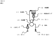
図2は、図1の設備中の冷凍機の詳細構成例図である。図2において、8は冷凍機内を
循環する冷水、9は一次ポンプ、10は冷凍機、11は冷凍機内を循環する冷却水、12
は冷却塔、13は冷却水ポンプ、14は冷却水入口温度監視点、15は冷水入口温度監視
点、16は冷水出口温度・冷水流量監視点である。冷水は一次ポンプにより冷水槽(図示
なし)より汲み上げられて冷凍機へ送られ、冷却されて冷水槽に戻される。
FIG. 2 is a detailed configuration diagram of the refrigerator in the facility of FIG. In FIG. 2, 8 is cold water circulating in the refrigerator, 9 is a primary pump, 10 is a refrigerator, 11 is cooling water circulating in the refrigerator, 12
Is a cooling tower, 13 is a cooling water pump, 14 is a cooling water inlet temperature monitoring point, 15 is a cold water inlet temperature monitoring point, and 16 is a cooling water outlet temperature / cooling water flow rate monitoring point. The cold water is drawn up from a cold water tank (not shown) by a primary pump, sent to a refrigerator, cooled, and returned to the cold water tank.
一方冷水を冷やす冷媒(図示なし)を冷却するための冷却水も冷凍機内を循環して、冷
却塔にて熱を屋外へ放出して、冷却水ポンプにより冷凍機へ戻す。これが繰り返される。
14の冷却水入口温度監視点では冷却水入口温度T11が検出される。15の冷水入口温
度監視点では冷水入口温度T12が検出される。16の冷水出口温度・冷水流量監視点で
は冷水出口温度T13と冷水流量Q11が検出される。14と15と16の検出される情
報は図1の運転制御部2に入力される。
On the other hand, the cooling water for cooling the refrigerant (not shown) for cooling the cold water also circulates in the refrigerator, releases heat to the outdoors in the cooling tower, and returns to the refrigerator by the cooling water pump. This is repeated.
The cooling water inlet temperature T11 is detected at 14 cooling water inlet temperature monitoring points. The cold water inlet temperature T12 is detected at 15 cold water inlet temperature monitoring points. The cold water outlet temperature T13 and the cold water flow rate Q11 are detected at the 16 cold water outlet temperature / cold water flow rate monitoring points. Information detected by 14, 15 and 16 is input to the
図3は、図2の冷凍機の部分負荷特性の実施例の図である。図3において、冷凍機の性
能を表す部分負荷特性は、横軸を冷凍容量、縦軸を消費電力としたグラフで、製造する冷
水温度(冷水出口温度)時に冷却水入口温度の違いによる特性を表したものである。この
ように冷凍機のモデル化においては、冷却水入口温度毎の特性が必要になる。
FIG. 3 is a diagram of an example of partial load characteristics of the refrigerator of FIG. In FIG. 3, the partial load characteristic representing the performance of the refrigerator is a graph with the refrigeration capacity on the horizontal axis and the power consumption on the vertical axis, and shows the characteristics due to the difference in the cooling water inlet temperature at the chilled water temperature to be manufactured (chilled water outlet temperature). It is a representation. Thus, in modeling the refrigerator, characteristics for each cooling water inlet temperature are required.
図4は、図2の冷凍機の稼働実績データから近似式を自動生成してモデル化する手順の
説明図である。
FIG. 4 is an explanatory diagram of a procedure for automatically generating an approximate expression from the operation result data of the refrigerator of FIG. 2 and modeling it.
図4において、
(1)冷凍機の稼働実績データから冷却水入口温度別にデータを抽出する。温度の最小単
位は0.1℃であるが、データ件数および効率的な処理を行うために例えば小数点以下は
四捨五入して1℃刻みのデータに丸めて抽出する。尚、処理実行時の条件設定によりデー
タ抽出の温度単位は可変にできる。(ステップS402)
(2)冷却水入口温度別に抽出した実績データには、計測誤差や運転開始直後のデータ等
に誤ったデータが含まれるため、それぞれについて外れ値を棄却して有効なデータに絞り
込む。(ステップS403)
(3)有効と判断した実績データから最小二乗法により2次関数の近似式と近似式の決定
係数を求める。近似式の算出にはハウスホルダー法を用いて実績データを行列で表して、
ハウスホルダー変換により上三角行列とした行列を解くことで2次関数の定数a、定数b
、定数cを求めるものである。決定係数は近似式が実績データにどの程度近似しているか
を0〜1の値で表したものとして算出する。(ステップS404)
(4)通常、冷凍機の特性は2次関数で表されて、かつ右上がりの曲線を示すのが一般的
である。
しかし、生成した近似式がこの冷凍機特性の実態に著しく適合しない結果であれば、生成
された近似式は有効とは言えないため、不採用として間引く処理を行う。(ステップS4
05)
(5)冷凍機は、例えば定格の冷凍容量の20%〜100%の範囲で動作する特性が示さ
れている場合、生成した近似式も同様なデータ範囲として適用することになる。しかし、
稼働時の実績データの範囲は限られるため、限られた範囲のデータから生成された2次関
数を適用すると右上がりとはならず、冷凍容量の範囲20%〜100%に頂点を含む下に
凸の近似になる。よって、1次関数の近似式も適用して、1次と2次の近似式を融合した
近似式を再生成する。もしくは2次関数の近似式において、実績データの下限部分を接点とした接線を適用して、2次関数とその接線とを結合した2次関数の近似式を再生成する方法のいずれかを適用する。(ステップS406)
(6)(4)により間引いた近似式を(5)の近似式を元にして再生する。
In FIG.
(1) Extract data for each cooling water inlet temperature from the operation data of the refrigerator. Although the minimum unit of temperature is 0.1 ° C., in order to perform the number of data and efficient processing, for example, the data after the decimal point is rounded off and rounded to 1 ° C. data and extracted. Note that the temperature unit for data extraction can be made variable by setting the conditions at the time of processing execution. (Step S402)
(2) Since the actual data extracted for each cooling water inlet temperature includes erroneous data in measurement errors, data immediately after the start of operation, etc., outliers are rejected and narrowed down to valid data. (Step S403)
(3) An approximate expression of a quadratic function and a determination coefficient of the approximate expression are obtained from the result data determined to be valid by the least square method. To calculate the approximate expression, use the Householder method to represent the actual data as a matrix,
Constant function a and constant b of the quadratic function by solving the upper triangular matrix by Householder transformation
The constant c is obtained. The determination coefficient is calculated as a value of 0 to 1 indicating how close the approximate expression is to the actual data. (Step S404)
(4) Usually, the characteristics of the refrigerator are generally expressed by a quadratic function and show a curve that rises to the right.
However, if the generated approximate expression does not remarkably match the actual condition of the refrigerator characteristics, the generated approximate expression cannot be said to be effective, and the thinning process is performed because it is not adopted. (Step S4
05)
(5) If the refrigerator operates, for example, when the characteristic of operating in the range of 20% to 100% of the rated refrigeration capacity is shown, the generated approximate expression is also applied as a similar data range. But,
Since the range of actual data at the time of operation is limited, applying a quadratic function generated from data in a limited range does not increase to the right, and the refrigeration capacity ranges from 20% to 100% including the peak. It becomes a convex approximation. Therefore, an approximate expression obtained by merging the primary and secondary approximate expressions is also regenerated by applying an approximate expression of a linear function. Or, in the approximate expression of the quadratic function, apply one of the methods to regenerate the approximate expression of the quadratic function that combines the quadratic function and its tangent by applying the tangent with the lower limit part of the actual data as the contact point To do. (Step S406)
(6) The approximate expression thinned out in (4) is reproduced based on the approximate expression in (5).
2つの近似式の間に間引いた近似式がある場合は、2つの近似式間に均等にデータをプ
ロットして、そのデータを元に2次の近似式を生成する。1つの近似式しか利用できない
場合は、その近似式の重心の消費電力をその冷凍機の定格消費電力で割った値(以下、%
kWと称する)と、再生する冷却水入口温度をパラメータとして得られるデータの重心の
%kWを比較して、その変化分だけ、元になる近似式を平行移動して再生する。
以上の処理により、1℃刻みの近似式が生成され、さらに冷凍機の省エネ計算に適用する
ために、0.1℃単位の近似式に細分する。(ステップS407)
(7)冷凍機の特性を示す近似式を自動生成してモデル化を完了した結果は、学習履歴と
して保存して、任意のタイミングで取り出しが可能とする。(ステップS408)
図5は、図4の実績データの棄却検定の手順の説明図である。
図5において、以下のような処理を行う。
(1)実績データの多くはアナログ値であるため、冷凍機が停止中であってもゼロを指し
示すとは限らない。よって、冷凍機停止中のデータを除外する。(ステップS502)
(2)冷凍機の仕様値の範囲チェックにより、能力以上の値となる外れ値等の誤ったデー
タを除外する。(ステップS503)
(3)実績データの%RT、%kWの平均から、それぞれの標準偏差σを算出して、2σ
を以上のばらつきのデータを除外して棄却する。ここで、%RTとは、冷凍機の製造熱量
をその冷凍機の定格冷凍容量で割った値とする。(ステップS504)
(4)(3)までの棄却にて残った実績データを元にして近似式を生成して、その近似式
の%kWの±10%以外のデータを除外する。さらに除外後の残った実績データより近似式を生成する。(ステップS505)
図6は、図4の生成した近似式から不適合な近似式を間引く手順の説明図である。
When there is an approximate expression thinned between two approximate expressions, data is evenly plotted between the two approximate expressions, and a second-order approximate expression is generated based on the data. When only one approximate expression can be used, the value obtained by dividing the power consumption at the center of gravity of the approximate expression by the rated power consumption of the refrigerator (hereinafter,%
(referred to as kW), the% kW of the center of gravity of the data obtained using the cooling water inlet temperature to be regenerated as a parameter is compared, and the original approximate expression is translated and regenerated by the change.
By the above processing, an approximate expression in increments of 1 ° C. is generated, and further subdivided into approximate expressions in units of 0.1 ° C. in order to apply to the energy saving calculation of the refrigerator. (Step S407)
(7) The result of automatically generating an approximate expression indicating the characteristics of the refrigerator and completing the modeling is saved as a learning history and can be taken out at an arbitrary timing. (Step S408)
FIG. 5 is an explanatory diagram of the procedure for rejecting the actual data shown in FIG.
In FIG. 5, the following processing is performed.
(1) Since most of the performance data is analog values, it does not always indicate zero even when the refrigerator is stopped. Therefore, data when the refrigerator is stopped is excluded. (Step S502)
(2) Exclude erroneous data such as outliers that exceed the capacity by checking the specification value range of the refrigerator. (Step S503)
(3) Calculate the respective standard deviations σ from the average of% RT and% kW of the actual data, and 2σ
Is rejected by excluding the above data of variation. Here,% RT is a value obtained by dividing the manufacturing heat quantity of a refrigerator by the rated refrigeration capacity of the refrigerator. (Step S504)
(4) An approximate expression is generated based on the actual data remaining after the rejection up to (3), and data other than ± 10% of% kW of the approximate expression is excluded. Further, an approximate expression is generated from the remaining record data after the exclusion. (Step S505)
FIG. 6 is an explanatory diagram of a procedure for thinning out an incompatible approximate expression from the generated approximate expression of FIG.
図6において、以下のような処理を行う。
(1)実績データのサンプル数が極端に少ない場合は、生成した近似式の信憑性に欠ける
ため、近似式を不採用として除外する。例えば最小件数100件とするが、計算開始時の
条件設定により可変となる。(ステップS602)
(2)生成した近似式の決定係数が0.5未満は、不採用として除外する。(ステップS
603)
(3)実績データが飛び石状になっている場合は、生成された近似式も信憑性に欠けるた
め、実績データの分布密度を算出して、飛び石のデータ分布の近似式は不採用として除外
する。(ステップS604)
(4)冷凍機の特性は一般的に右上がりの2次関数のため、実態に適合しないと判断でき
る近似式を不採用として除外する。具体的には、近似式の定数aがマイナスは、上に凸の
ため除外し、複数の近似式と交点を持つ近似式は除外し、冷凍容量の範囲に頂点を持ち冷
凍容量下限の%kW値が極端に大きな近似式は除外する。(ステップS605)
図7は、図4の1次と2次の近似式を結合する方法の一例を示す図である。
In FIG. 6, the following processing is performed.
(1) When the number of samples of the performance data is extremely small, since the credibility of the generated approximate expression is lacking, the approximate expression is excluded as not adopted. For example, although the minimum number is 100, it is variable depending on the condition setting at the start of calculation. (Step S602)
(2) If the determination coefficient of the generated approximate expression is less than 0.5, it is excluded as not adopted. (Step S
603)
(3) If the performance data has a stepping stone shape, the generated approximate expression is also not credible, so the distribution density of the performance data is calculated and the stepping stone data distribution approximation expression is excluded as not adopted. . (Step S604)
(4) Since the characteristic of the refrigerator is generally a quadratic function that rises to the right, an approximate expression that can be determined to be incompatible with the actual situation is excluded as not adopted. Specifically, when the constant a of the approximate expression is minus, it is excluded because it is convex upward, and the approximate expression having an intersection with a plurality of approximate expressions is excluded, and the refrigeration capacity range has an apex in the refrigeration capacity lower limit% kW Approximate expressions with extremely large values are excluded. (Step S605)
FIG. 7 is a diagram illustrating an example of a method of combining the first-order and second-order approximate expressions of FIG.
図7において、2次の近似式をそのまま適用すると、%RTが20%近辺は左上がりの
曲線となり、冷凍機の特性の実態とかけ離れるため、1次の近似式と結合して太字破線で
示す2次の近似式を再生成する。
In FIG. 7, when the second order approximate expression is applied as it is, the curve where% RT is about 20% rises to the left and differs from the actual characteristics of the refrigerator. Regenerate the quadratic approximation shown.
2次と1次の接点を求めて、接点を境にして2次の近似式のデータプロットと1次近似
式のデータプロットを使って再生成する。1次の近似式はそのまま使用せずに、接点から
%RTが20%の点にかけての直線を1次の近似式と補正して使用する。
Secondary contact points and primary contact points are obtained, and are regenerated using the data plot of the secondary approximate expression and the data plot of the primary approximate expression at the contact point. Instead of using the first order approximate expression as it is, a straight line from the contact point to the point where% RT is 20% is corrected and used as the first order approximate expression.
図8は、図4の間引いた近似式を補正・補間して再生成する方法一例を示す図である。 FIG. 8 is a diagram showing an example of a method for regenerating by correcting / interpolating the approximate expression thinned out in FIG.
図8において、太線の冷却水入口温度20℃と30℃の2つの近似式のみが間引かれて
残った例である。この2つの近似式の%RTを5等分した%kWの値を均等に補間した値
を算出して、この値から近似式を再生成して補間する。一方31℃と32℃は実績データ
の重心を求めて、その%kWの値と30℃の近似式の重心の%kWの値との変化分から3
0℃の近似式を補正して再生成する。
FIG. 8 shows an example in which only two approximate equations of thick line cooling
Regenerate by correcting the approximate expression at 0 ° C.
図9は、図4の実績データ棄却検定の一例を示す図である。 FIG. 9 is a diagram illustrating an example of the result data rejection test of FIG.
図9において、実績データのある冷却水入口温度のデータ分布の一例で、範囲チェック
、2σ、仮の近似式の上下方向のチェックから外れ値を棄却した結果である。
FIG. 9 shows an example of data distribution of cooling water inlet temperature with actual data, which is a result of rejecting an outlier from a range check, 2σ, and a vertical check of a temporary approximate expression.
図9では、大きな囲いの枠の中に更に囲いの枠がある。先ず、図5に示した手順に従い
、中の囲いの枠よりも外側で、大きな囲いの枠の内側にある実績データは、範囲チェック
により棄却される(図5のステップS503)。次に、中の囲いの枠内部の実績データの
標準偏差の2σから逸脱するデータを棄却される(図5のステップS504)。その結果
、図9の中の囲いの枠の頂点部の近傍にある2つの円内部の実績データが棄却されること
になる。その後、残った実績データから2次関数の近似式を生成して、近似式の上下方向
の実績データを棄却する(図5のステップS505)。
In FIG. 9, there is a further enclosure frame in the large enclosure frame. First, according to the procedure shown in FIG. 5, the actual data outside the inner enclosure and inside the larger enclosure is rejected by the range check (step S <b> 503 in FIG. 5). Next, data that deviates from 2σ of the standard deviation of the actual data inside the inner enclosure frame is rejected (step S504 in FIG. 5). As a result, the performance data inside the two circles in the vicinity of the apex of the enclosure frame in FIG. 9 is rejected. Thereafter, an approximate expression of a quadratic function is generated from the remaining record data, and the record data in the vertical direction of the approximate expression is rejected (step S505 in FIG. 5).
図10は、図4の近似式を間引いた一例を示す図である。 FIG. 10 is a diagram illustrating an example in which the approximate expression of FIG. 4 is thinned out.
図10において、冷却水入口温度別に生成した近似式を重ね合わせて表示した例から近
似式を間引いた結果の例を示す。
FIG. 10 shows an example of the result of thinning out the approximate expression from the example in which the approximate expression generated for each cooling water inlet temperature is superimposed and displayed.
図11は、図4の近似式を補正・補間した一例を示す図である。 FIG. 11 is a diagram illustrating an example in which the approximate expression of FIG. 4 is corrected and interpolated.
図11において、図10の間引かれた結果の3つの近似式から補正・補間して各冷却水
入口温度の近似式を再生成した結果である。
11 is a result of regenerating the approximate expression of each cooling water inlet temperature by correcting and interpolating from the three approximate expressions of the thinned result in FIG.
図12は、図1の冷凍負荷を配分するラグランジュ未定定数法適用の手順の説明図であ
る。
FIG. 12 is an explanatory diagram of a procedure of applying the Lagrange undetermined constant method for allocating the refrigeration load of FIG.
図12において、以下のような処理をする。
(1)空調側の負荷熱量は、図1の第1の温度・流量監視点6での冷水の温度T1と送水
量Q1および、第2の温度監視点7の冷水の戻り温度T2より、負荷熱量=温度差Δt×
送水量×3024より求められる。
(2)(1)の負荷熱量とその時に運転させる冷凍機のモデルを入力として、消費電力が
最小となる冷凍機への冷凍負荷の配分を算出する。
運転冷凍機の消費電力合計をモデルを元に表した目的関数と、負荷熱量の制約条件の2つ
の関係が成り立つ場合は、ラグランジュ未定定数λを含んだラグランジュ関数Lで表すこ
とができる。このラグランジュ関数Lを最小とした場合のxiとλを求めることにより、
省エネとなる冷凍機への負荷配分を決定できる。以下にその関係式(数1)、(数2)、
(数3)を示す。
In FIG. 12, the following processing is performed.
(1) The load heat amount on the air conditioning side is the cold water temperature T 1 and the water supply amount Q 1 at the first temperature / flow
It is calculated | required from the amount of water supply x3024.
(2) Using the load heat quantity of (1) and the model of the refrigerator operated at that time as input, distribution of the refrigeration load to the refrigerator having the minimum power consumption is calculated.
When the relationship between the objective function that represents the total power consumption of the operating refrigerator and the constraint condition of the load heat amount is established based on the model, it can be expressed by a Lagrangian function L including the Lagrange undetermined constant λ. By obtaining xi and λ when the Lagrangian function L is minimized,
It is possible to determine load distribution to refrigerators that save energy. The relational expressions (Equation 1), (Equation 2),
(Equation 3) is shown.
目的関数
総消費電力 F = Σ yi = Σ (ai xi2 + bi xi + ci) (数1)
i∈U i∈U
U :運転する冷凍機の集合
制約条件
需給バランス制約 D = Σ xi (数2)
i∈U
上下限制約 Li ≦ xi ≦ Ui
F :総消費電力
Xi :第i冷凍機の冷凍負荷の分担
D :負荷熱量
Ui :第i冷凍機の冷凍熱量の上限
Li :第i冷凍機の冷凍熱量の下限
λ :ラグランジュ乗数
ラグランジュ関数 L = Σ(ai xi2 + bi xi + ci)+ λ( D − Σ xi)(数3)
i∈U i∈U
Objective function Total power consumption F = Σ yi = Σ (ai xi 2 + bi xi + ci) (Equation 1)
i∈U i∈U
U: Set of operating refrigerators Constraints Supply / demand balance constraint D = Σ xi (Equation 2)
i∈U
Upper and lower limit constraints Li ≤ xi ≤ Ui
F: Total power consumption
Xi: Share of refrigeration load of i-th refrigerator
D: Load heat quantity
Ui: Upper limit of refrigeration heat quantity of i-th refrigerator
Li: Lower limit of refrigeration heat quantity of i-th refrigerator
λ: Lagrange multiplier Lagrange function L = Σ (ai xi 2 + bi xi + ci) + λ (D − Σ xi) (Equation 3)
i∈U i∈U
図13は、図4の2次の近似式と接線とを結合する方法の一例を示す図である。 FIG. 13 is a diagram illustrating an example of a method of combining the quadratic approximate expression of FIG. 4 and a tangent line.
図13において、図7の1次と2次の近似式を結合する方法の場合、実績データの傾向によっては、元にした1次の近似式が冷凍負荷%RTの20%付近の消費電力%kWが低めになる傾向がある。そのために実績データの下限値における2次の近似式のポイントを接点とした接線と、2次の近似式を結合して太字破線で示す2次の近似式を再生成する。
図7と図13のいずれかの方法は、処理実行前に選択可能とする。
In the case of the method of combining the primary and secondary approximate expressions of FIG. 7 in FIG. 13, the power consumption% in the vicinity of 20% of the refrigeration load% RT is determined based on the trend of the actual data. kW tends to be lower. For this purpose, a tangent line having the contact point at the point of the second order approximate expression in the lower limit of the actual data and the second order approximate expression are combined to regenerate a second order approximate expression indicated by a bold broken line.
Either of the methods in FIGS. 7 and 13 can be selected before the processing is executed.
1・・・冷凍機部、2・・・運転制御部、3・・・負荷部、4・・・冷水槽、5・・・調
相器、6・・・第1の温度・送水量監視点、7・・・第2の温度監視点、8・・・冷水、
9・・・一次ポンプ、10・・・冷凍機、11・・・冷却水、12・・・冷却塔、13・
・・冷却水ポンプ、14・・・冷却水入口温度監視点、15・・・冷水入口温度監視点、
16・・・冷水出口温度・冷水流量監視点、100・・・冷凍用設備。
DESCRIPTION OF
9 ... Primary pump, 10 ... Refrigerator, 11 ... Cooling water, 12 ... Cooling tower, 13.
..Cooling water pump, 14 ... cooling water inlet temperature monitoring point, 15 ... cold water inlet temperature monitoring point,
16 ... Cold water outlet temperature / cooling water flow rate monitoring point, 100 ... Refrigeration equipment.
Claims (3)
前記複数の冷凍機のそれぞれを運転させることにより、当該冷凍機の冷凍容量と消費電力との関係を示す稼動実績データを、当該冷凍機の冷媒を冷却するための冷却水の設定された温度毎に算出する稼動実績データ算出ステップと、
算出した前記稼動実績データに基づいて前記複数の冷凍機のそれぞれに対して、前記設定された温度毎の当該冷凍機の冷凍容量と消費電力との関係を示す近似式を生成する近似式生成ステップと、
前記複数の冷凍機に必要な冷凍容量に対して冷凍機の運転台数と運転する冷凍機の冷凍容量の配分を、前記複数の冷凍機のそれぞれの冷媒を冷却するための冷却水の温度から求められる負荷熱量の合計値と、前記近似式生成ステップにより生成した近似式と、を用いて総消費電力が最小となるように決定する決定ステップと、
該決定ステップにより決定した冷凍機の運転台数と運転する冷凍機の冷凍容量の配分に応じて前記複数の冷凍機を運転させるステップとを備え、
前記決定ステップでは、
前記近似式生成ステップにより生成した近似式のうち、当該近似式を生成するのに用いた稼動実績データのサンプル数が設定値以下の場合には、当該近似式を除外し、
該除外した近似式以外の近似式と、前記複数の冷凍機のそれぞれの冷媒を冷却するための冷却水の温度から求められる負荷熱量の合計値と、を用いて、前記複数の冷凍機に必要な冷凍容量に対して前記冷凍機の運転台数と運転する冷凍機の冷凍容量の配分を決定することを特徴とする複数の冷凍機の運転方法。 In the operation method of a plurality of refrigerators,
By operating each of the plurality of refrigerators, operation result data indicating the relationship between the refrigeration capacity of the refrigerator and the power consumption is obtained for each set temperature of cooling water for cooling the refrigerant of the refrigerator. and the operation performance data calculating step you calculated,
An approximate expression generating step for generating an approximate expression indicating the relationship between the refrigeration capacity and power consumption of the refrigerator for each set temperature for each of the plurality of refrigerators based on the calculated operation result data When,
The distribution of the number of chillers to be operated and the refrigeration capacity of the chillers to be operated with respect to the refrigeration capacity required for the plurality of chillers is obtained from the temperature of the cooling water for cooling the refrigerant of each of the chillers. A determination step of determining the total power consumption to be minimum using a total value of the load heat amount to be generated and the approximate expression generated by the approximate expression generation step;
Operating the plurality of refrigerators in accordance with the number of operating refrigerators determined in the determining step and the distribution of the refrigerating capacity of the operating refrigerators,
In the determination step,
Of the approximate formulas generated by the approximate formula generation step, if the number of samples of operation performance data used to generate the approximate formula is equal to or less than a set value, exclude the approximate formula,
Necessary for the plurality of refrigerators by using an approximate expression other than the excluded approximate expression and a total value of the load heat amount obtained from the temperature of the cooling water for cooling the refrigerant of each of the plurality of refrigerators. A method of operating a plurality of refrigerators, wherein the distribution of the number of refrigerators to be operated and the distribution of the refrigerator capacities of the refrigerators to be operated is determined with respect to an appropriate refrigerator capacity .
前記複数の冷凍機のそれぞれを運転させることにより、当該冷凍機の冷凍容量と消費電力との関係を示す稼動実績データを、当該冷凍機の冷媒を冷却するための冷却水の設定された温度毎に算出する稼動実績データ算出ステップと、
算出した前記稼動実績データに基づいて前記複数の冷凍機のそれぞれに対して、前記設定された温度毎の当該冷凍機の冷凍容量と消費電力との関係を示す近似式を生成する近似式生成ステップと、
前記複数の冷凍機に必要な冷凍容量に対して冷凍機の運転台数と運転する冷凍機の冷凍容量の配分を、前記複数の冷凍機のそれぞれの冷媒を冷却するための冷却水の温度から求められる負荷熱量の合計値と、前記近似式生成ステップにより生成した近似式と、を用いて総消費電力が最小となるように決定する決定ステップと、
該決定ステップにより決定した冷凍機の運転台数と運転する冷凍機の冷凍容量の配分に応じて前記複数の冷凍機を運転させるステップとを備え、
前記決定ステップでは、
前記近似式生成ステップにより生成した近似式のうち、当該近似式を生成するのに用いた稼動実績データの分布密度が設定値以下の場合には、当該近似式を除外し、
該除外した近似式以外の近似式と、前記複数の冷凍機のそれぞれの冷媒を冷却するための冷却水の温度から求められる熱負荷量の合計値と、を用いて、前記複数の冷凍機に必要な冷凍容量に対して前記冷凍機の運転台数と運転する冷凍機の冷凍容量の配分を決定することを特徴とする複数の冷凍機の運転方法。 In the operation method of a plurality of refrigerators,
By operating each of the plurality of refrigerators, operation result data indicating the relationship between the refrigeration capacity of the refrigerator and the power consumption is obtained for each set temperature of cooling water for cooling the refrigerant of the refrigerator. The operation result data calculation step to calculate
An approximate expression generating step for generating an approximate expression indicating the relationship between the refrigeration capacity and power consumption of the refrigerator for each set temperature for each of the plurality of refrigerators based on the calculated operation result data When,
The distribution of the number of chillers to be operated and the refrigeration capacity of the chillers to be operated with respect to the refrigeration capacity required for the plurality of chillers is obtained from the temperature of the cooling water for cooling the refrigerant of each of the chillers. A determination step of determining the total power consumption to be minimum using a total value of the load heat amount to be generated and the approximate expression generated by the approximate expression generation step;
Operating the plurality of refrigerators in accordance with the number of operating refrigerators determined in the determining step and the distribution of the refrigerating capacity of the operating refrigerators ,
In the determination step,
Of the approximate formulas generated by the approximate formula generation step, if the distribution density of the actual performance data used to generate the approximate formula is equal to or less than a set value, the approximate formula is excluded,
Using the approximate expression other than the excluded approximate expression and the total value of the heat load obtained from the temperature of the cooling water for cooling the refrigerant of each of the plurality of refrigerators, the plurality of refrigerators A method of operating a plurality of refrigerators , wherein the number of operating refrigerators and the distribution of the refrigerator capacity of the refrigerators to be operated are determined with respect to a required refrigerator capacity .
前記複数の冷凍機のそれぞれを運転させることにより、当該冷凍機の冷凍容量と消費電力との関係を示す稼動実績データを、当該冷凍機の冷媒を冷却するための冷却水の設定された温度毎に算出する稼動実績データ算出ステップと、
算出した前記稼動実績データに基づいて前記複数の冷凍機のそれぞれに対して、前記設定された温度毎の当該冷凍機の冷凍容量と消費電力との関係を示す近似式を生成する近似式生成ステップと、
前記複数の冷凍機に必要な冷凍容量に対して冷凍機の運転台数と運転する冷凍機の冷凍容量の配分を、前記複数の冷凍機のそれぞれの冷媒を冷却するための冷却水の温度から求められる負荷熱量の合計値と、前記近似式生成ステップにより生成した近似式と、を用いて総消費電力が最小となるように決定する決定ステップと、
該決定ステップにより決定した冷凍機の運転台数と運転する冷凍機の冷凍容量の配分に応じて前記複数の冷凍機を運転させるステップとを備え、
前記決定ステップでは、
前記近似式生成ステップにより生成した近似式のうち、他の近似式と設定回数以上の交点を有する近似式を除外し、
該除外した近似式以外の近似式と、前記複数の冷凍機のそれぞれの冷媒を冷却するための冷却水の温度から求められる負荷熱量の合計値と、を用いて、前記複数の冷凍機に必要な冷凍容量に対して前記冷凍機の運転台数と運転する冷凍機の冷凍容量の配分を決定することを特徴とする複数の冷凍機の運転方法。 In the operation method of a plurality of refrigerators,
By operating each of the plurality of refrigerators, operation result data indicating the relationship between the refrigeration capacity of the refrigerator and the power consumption is obtained for each set temperature of cooling water for cooling the refrigerant of the refrigerator. The operation result data calculation step to calculate
For each based on the operation result data issued calculated of the plurality of refrigerators, generates approximate expression for generating an approximate expression indicating the relationship between the power consumption refrigeration capacity of the refrigerator for each of the set temperature Steps,
The distribution of the number of chillers to be operated and the refrigeration capacity of the chillers to be operated with respect to the refrigeration capacity required for the plurality of chillers is obtained from the temperature of the cooling water for cooling the refrigerant of each of the chillers. A determination step of determining the total power consumption to be minimum using a total value of the load heat amount to be generated and the approximate expression generated by the approximate expression generation step;
Operating the plurality of refrigerators in accordance with the number of operating refrigerators determined in the determining step and the distribution of the refrigerating capacity of the operating refrigerators ,
In the determination step,
Of the approximate expressions generated by the approximate expression generating step, exclude approximate expressions having intersections with other approximate expressions or more than the set number of times,
Necessary for the plurality of refrigerators by using an approximate expression other than the excluded approximate expression and a total value of the load heat amount obtained from the temperature of the cooling water for cooling the refrigerant of each of the plurality of refrigerators. A method of operating a plurality of refrigerators, wherein the distribution of the number of refrigerators to be operated and the distribution of the refrigerator capacities of the refrigerators to be operated is determined with respect to an appropriate refrigerator capacity .
Priority Applications (1)
| Application Number | Priority Date | Filing Date | Title |
|---|---|---|---|
| JP2006230007A JP4857051B2 (en) | 2006-03-01 | 2006-08-28 | Refrigerator equipment operation method and equipment comprising a refrigerator |
Applications Claiming Priority (3)
| Application Number | Priority Date | Filing Date | Title |
|---|---|---|---|
| JP2006054288 | 2006-03-01 | ||
| JP2006054288 | 2006-03-01 | ||
| JP2006230007A JP4857051B2 (en) | 2006-03-01 | 2006-08-28 | Refrigerator equipment operation method and equipment comprising a refrigerator |
Publications (2)
| Publication Number | Publication Date |
|---|---|
| JP2007263546A JP2007263546A (en) | 2007-10-11 |
| JP4857051B2 true JP4857051B2 (en) | 2012-01-18 |
Family
ID=38636699
Family Applications (1)
| Application Number | Title | Priority Date | Filing Date |
|---|---|---|---|
| JP2006230007A Active JP4857051B2 (en) | 2006-03-01 | 2006-08-28 | Refrigerator equipment operation method and equipment comprising a refrigerator |
Country Status (1)
| Country | Link |
|---|---|
| JP (1) | JP4857051B2 (en) |
Families Citing this family (6)
| Publication number | Priority date | Publication date | Assignee | Title |
|---|---|---|---|---|
| JP2009216259A (en) * | 2008-03-07 | 2009-09-24 | Hitachi Industrial Equipment Systems Co Ltd | Operating method of refrigerator equipment and refrigerator equipment |
| JP5312286B2 (en) * | 2009-10-21 | 2013-10-09 | 三菱電機株式会社 | Air conditioner control device, refrigeration device control device |
| JP4980407B2 (en) | 2009-10-21 | 2012-07-18 | 三菱電機株式会社 | Air conditioner control device, refrigeration device control device |
| JP5473619B2 (en) * | 2010-01-12 | 2014-04-16 | 三菱電機株式会社 | Air conditioner control device |
| JP6270324B2 (en) * | 2013-03-12 | 2018-01-31 | サントリーホールディングス株式会社 | Heat pump operation method and heat supply system using the heat pump operation method |
| JP2020016992A (en) * | 2018-07-24 | 2020-01-30 | 株式会社日立製作所 | Characteristic model automatic generation system and characteristic model automatic generation method |
Family Cites Families (4)
| Publication number | Priority date | Publication date | Assignee | Title |
|---|---|---|---|---|
| JP3479861B2 (en) * | 1995-11-28 | 2003-12-15 | 株式会社日立製作所 | Operation control method for multiple refrigerators |
| JP2002271981A (en) * | 2001-03-14 | 2002-09-20 | Hitachi Ltd | Electricity unit price setting method and electric unit price provision service |
| JP4186450B2 (en) * | 2001-10-16 | 2008-11-26 | 株式会社日立製作所 | Air conditioning equipment operation system and air conditioning equipment design support system |
| JP4435533B2 (en) * | 2003-10-09 | 2010-03-17 | 高砂熱学工業株式会社 | Heat source system and control device |
-
2006
- 2006-08-28 JP JP2006230007A patent/JP4857051B2/en active Active
Also Published As
| Publication number | Publication date |
|---|---|
| JP2007263546A (en) | 2007-10-11 |
Similar Documents
| Publication | Publication Date | Title |
|---|---|---|
| US11973345B2 (en) | Building energy system with predictive control of battery and green energy resources | |
| CN110736227B (en) | Building management system with online configurable system identification | |
| US20220268471A1 (en) | Building equipment with predictive control | |
| EP3317597B1 (en) | System and the associated method for controlling a refrigeration or hvac system | |
| US20190032942A1 (en) | Central plant control system with computation reduction based on stranded node analysis | |
| US20220186962A1 (en) | Building equipment with predictive control and allocation of energy from multiple energy sources | |
| KR101754536B1 (en) | Method and apparatus for optimum control of refrigerator using building energy management system | |
| CN106066077A (en) | There is the HVAC controller that forecast cost optimizes | |
| CN107923645A (en) | Air conditioning operation analysis device and program | |
| US20180216842A1 (en) | Systems and methods for monitoring and controlling an energy plant | |
| WO2021082478A1 (en) | Energy consumption prediction method and device for air conditioning system | |
| US20240353160A1 (en) | Air conditioner and air conditioning system | |
| US20250244034A1 (en) | A system for controlling chilled water plant | |
| JP4857051B2 (en) | Refrigerator equipment operation method and equipment comprising a refrigerator | |
| JP2013087991A (en) | Heat source control device, air-conditioning system, heat source control program, and heat source control method | |
| Sanchez et al. | Modelling and mitigating lifetime impact of building demand responsive control of heating, ventilation and air-conditioning systems | |
| CN105987486A (en) | Heat demand estimation device and method, facility control device, method and system | |
| US11226600B2 (en) | Building control system with load curtailment optimization | |
| KR102090281B1 (en) | Cooling energy performance evaluation system in data center building and method of the same | |
| Satué et al. | Economic MPC Optimization of a cold production plant with energy storage | |
| KR20240054490A (en) | Ai based temperature detecting method for high energy efficiency of logistics center | |
| EP4465778A1 (en) | Accurate estimation of data center cooling capacity with a cooling topology service | |
| Zabala Urrutia et al. | Heuristic mathematical optimization of heat pumps in cascade to reduce energy consumption | |
| Zulkafli et al. | Optimal Planning of Multi-Compressors Refrigeration System for Maximising Efficiency with the Influence of Weather Condition | |
| CN121383351A (en) | A fault detection method, system, device and medium |
Legal Events
| Date | Code | Title | Description |
|---|---|---|---|
| A621 | Written request for application examination |
Free format text: JAPANESE INTERMEDIATE CODE: A621 Effective date: 20080901 |
|
| A521 | Written amendment |
Free format text: JAPANESE INTERMEDIATE CODE: A523 Effective date: 20080901 |
|
| A977 | Report on retrieval |
Free format text: JAPANESE INTERMEDIATE CODE: A971007 Effective date: 20100811 |
|
| A131 | Notification of reasons for refusal |
Free format text: JAPANESE INTERMEDIATE CODE: A131 Effective date: 20101124 |
|
| A521 | Written amendment |
Free format text: JAPANESE INTERMEDIATE CODE: A523 Effective date: 20110124 |
|
| A131 | Notification of reasons for refusal |
Free format text: JAPANESE INTERMEDIATE CODE: A131 Effective date: 20110517 |
|
| A521 | Written amendment |
Free format text: JAPANESE INTERMEDIATE CODE: A523 Effective date: 20110708 |
|
| TRDD | Decision of grant or rejection written | ||
| A01 | Written decision to grant a patent or to grant a registration (utility model) |
Free format text: JAPANESE INTERMEDIATE CODE: A01 Effective date: 20111004 |
|
| A01 | Written decision to grant a patent or to grant a registration (utility model) |
Free format text: JAPANESE INTERMEDIATE CODE: A01 |
|
| A61 | First payment of annual fees (during grant procedure) |
Free format text: JAPANESE INTERMEDIATE CODE: A61 Effective date: 20111031 |
|
| FPAY | Renewal fee payment (event date is renewal date of database) |
Free format text: PAYMENT UNTIL: 20141104 Year of fee payment: 3 |
|
| R150 | Certificate of patent or registration of utility model |
Ref document number: 4857051 Country of ref document: JP Free format text: JAPANESE INTERMEDIATE CODE: R150 Free format text: JAPANESE INTERMEDIATE CODE: R150 |