JP4852970B2 - Power supply system - Google Patents
Power supply system Download PDFInfo
- Publication number
- JP4852970B2 JP4852970B2 JP2005311087A JP2005311087A JP4852970B2 JP 4852970 B2 JP4852970 B2 JP 4852970B2 JP 2005311087 A JP2005311087 A JP 2005311087A JP 2005311087 A JP2005311087 A JP 2005311087A JP 4852970 B2 JP4852970 B2 JP 4852970B2
- Authority
- JP
- Japan
- Prior art keywords
- power
- core
- primary
- power supply
- cores
- Prior art date
- Legal status (The legal status is an assumption and is not a legal conclusion. Google has not performed a legal analysis and makes no representation as to the accuracy of the status listed.)
- Expired - Fee Related
Links
Images


Classifications
-
- H—ELECTRICITY
- H02—GENERATION; CONVERSION OR DISTRIBUTION OF ELECTRIC POWER
- H02J—CIRCUIT ARRANGEMENTS OR SYSTEMS FOR SUPPLYING OR DISTRIBUTING ELECTRIC POWER; SYSTEMS FOR STORING ELECTRIC ENERGY
- H02J50/00—Circuit arrangements or systems for wireless supply or distribution of electric power
- H02J50/40—Circuit arrangements or systems for wireless supply or distribution of electric power using two or more transmitting or receiving devices
- H02J50/402—Circuit arrangements or systems for wireless supply or distribution of electric power using two or more transmitting or receiving devices the two or more transmitting or the two or more receiving devices being integrated in the same unit, e.g. power mats with several coils or antennas with several sub-antennas
-
- H—ELECTRICITY
- H01—ELECTRIC ELEMENTS
- H01F—MAGNETS; INDUCTANCES; TRANSFORMERS; SELECTION OF MATERIALS FOR THEIR MAGNETIC PROPERTIES
- H01F38/00—Adaptations of transformers or inductances for specific applications or functions
- H01F38/14—Inductive couplings
-
- H—ELECTRICITY
- H02—GENERATION; CONVERSION OR DISTRIBUTION OF ELECTRIC POWER
- H02J—CIRCUIT ARRANGEMENTS OR SYSTEMS FOR SUPPLYING OR DISTRIBUTING ELECTRIC POWER; SYSTEMS FOR STORING ELECTRIC ENERGY
- H02J50/00—Circuit arrangements or systems for wireless supply or distribution of electric power
- H02J50/10—Circuit arrangements or systems for wireless supply or distribution of electric power using inductive coupling
- H02J50/12—Circuit arrangements or systems for wireless supply or distribution of electric power using inductive coupling of the resonant type
-
- H—ELECTRICITY
- H02—GENERATION; CONVERSION OR DISTRIBUTION OF ELECTRIC POWER
- H02J—CIRCUIT ARRANGEMENTS OR SYSTEMS FOR SUPPLYING OR DISTRIBUTING ELECTRIC POWER; SYSTEMS FOR STORING ELECTRIC ENERGY
- H02J7/00—Circuit arrangements for charging or depolarising batteries or for supplying loads from batteries
- H02J7/02—Circuit arrangements for charging or depolarising batteries or for supplying loads from batteries for charging batteries from AC mains by converters
-
- H—ELECTRICITY
- H01—ELECTRIC ELEMENTS
- H01F—MAGNETS; INDUCTANCES; TRANSFORMERS; SELECTION OF MATERIALS FOR THEIR MAGNETIC PROPERTIES
- H01F3/00—Cores, Yokes, or armatures
-
- H—ELECTRICITY
- H01—ELECTRIC ELEMENTS
- H01F—MAGNETS; INDUCTANCES; TRANSFORMERS; SELECTION OF MATERIALS FOR THEIR MAGNETIC PROPERTIES
- H01F30/00—Fixed transformers not covered by group H01F19/00
- H01F30/04—Fixed transformers not covered by group H01F19/00 having two or more secondary windings, each supplying a separate load, e.g. for radio set power supplies
-
- H—ELECTRICITY
- H02—GENERATION; CONVERSION OR DISTRIBUTION OF ELECTRIC POWER
- H02J—CIRCUIT ARRANGEMENTS OR SYSTEMS FOR SUPPLYING OR DISTRIBUTING ELECTRIC POWER; SYSTEMS FOR STORING ELECTRIC ENERGY
- H02J50/00—Circuit arrangements or systems for wireless supply or distribution of electric power
- H02J50/005—Mechanical details of housing or structure aiming to accommodate the power transfer means, e.g. mechanical integration of coils, antennas or transducers into emitting or receiving devices
-
- H—ELECTRICITY
- H02—GENERATION; CONVERSION OR DISTRIBUTION OF ELECTRIC POWER
- H02J—CIRCUIT ARRANGEMENTS OR SYSTEMS FOR SUPPLYING OR DISTRIBUTING ELECTRIC POWER; SYSTEMS FOR STORING ELECTRIC ENERGY
- H02J50/00—Circuit arrangements or systems for wireless supply or distribution of electric power
- H02J50/70—Circuit arrangements or systems for wireless supply or distribution of electric power involving the reduction of electric, magnetic or electromagnetic leakage fields
Landscapes
- Engineering & Computer Science (AREA)
- Power Engineering (AREA)
- Computer Networks & Wireless Communication (AREA)
- Charge And Discharge Circuits For Batteries Or The Like (AREA)
- Dry Shavers And Clippers (AREA)
- Coils Of Transformers For General Uses (AREA)
Description
本発明は、単一の電源アダプタから複数の負荷機器へ給電可能な給電システムに関し、特に電磁誘導による無接点の電力伝送で給電が行われるものに関する。 The present invention relates to a power supply system capable of supplying power to a plurality of load devices from a single power adapter, and particularly relates to a power supply system that performs power supply by contactless power transmission using electromagnetic induction.
上述のように単一の電源アダプタから複数の負荷機器へ給電可能な給電システムとしては、洗浄装置付き電気カミソリの例が挙げられる。図21は、その給電システムの構成を示す図である。RCC(リンギングチョークコンバータ)などから成る電源アダプタ1に対して、図21(a)で示すように電気カミソリ2が接続可能であり、また図21(b)で示すように洗浄装置3が接続可能となっている。そして、図21(b)で示すように、洗浄装置3に電気カミソリ2を搭載した状態で、該電気カミソリ2の刃先の洗浄が行われるだけでなく、該電気カミソリ2の充電も可能となっている。
As described above, an example of an electric razor with a cleaning device can be given as a power supply system that can supply power to a plurality of load devices from a single power adapter. FIG. 21 is a diagram illustrating a configuration of the power feeding system. An electric razor 2 can be connected to the
しかしながら、この場合、電源アダプタ1は、DCで、たとえば12Vを出力しているので、洗浄装置3内の洗浄用駆動回路4や洗浄装置3に搭載された電気カミソリ2への充電がそのまま線路の分岐で実現できているけれども、電源アダプタ1は、接触式の接点5によって前記洗浄装置3または電気カミソリ2に接続される必要がある。また、電源アダプタ1は、消費電力の大きい洗浄装置3に対応して、前記12Vの高電圧で電源供給するので、電気カミソリ2内には、2次電池6の充電に適した電圧に降圧する降圧電源7が必要になり、電気カミソリ2が大型化する。
However, in this case, since the
一方、洗面所などの水回りで使用されることの多い電気カミソリには、非接触(無接点)で給電したいという要望がある。図22に、従来の非接触給電を実現する給電システムの構成を示す。電源コード11を介して電源アダプタ12に入力された商用交流は、コンバータ13において直流に変換され、電圧共振型インバータ14において高周波交流に変換されて、該電源アダプタ12側の出力端子である1次コイル15から出力される。
On the other hand, electric razors that are often used around water, such as a washroom, have a desire to supply power without contact (contactless). FIG. 22 shows a configuration of a conventional power feeding system that realizes contactless power feeding. The commercial alternating current input to the
前記1次コイル15は、電気カミソリ16側の入力端子である2次コイル17と着脱可能に磁気結合しており、その2次コイル17に発生した交流電圧は、コンバータ回路18で直流電圧に変換された後、2次電池およびモータから成る負荷19へ給電される。前記コンバータ回路18は、AC−DCコンバータであり、前述の降圧電源7のDC−DCコンバータに比べて、小型である。
The
したがって、この図22で示す非接触の給電システムを、図21で示す洗浄装置3を含む複数の負荷機器が接続可能な給電システムに適用した場合、図23で示すようになる。電源アダプタ21は、電圧共振型インバータなどから成り、ACで、たとえば50kHz、30Vを、送電コイル24へ出力する。その送電コイル24に対して、図23(a)で示すように電気カミソリ22の受電コイル25が非接触で接続可能であり、また図23(b)で示すように洗浄装置23の受電コイル26が非接触で接続可能となっている。
Therefore, when the non-contact power supply system shown in FIG. 22 is applied to a power supply system to which a plurality of load devices including the cleaning device 3 shown in FIG. 21 can be connected, the result is as shown in FIG. The
そして、図23(b)で示すように、洗浄装置23内には、AC−DCコンバータ27が設けられており、このAC−DCコンバータ27によって、たとえばDC12Vが作成され、洗浄用駆動回路28に供給される。また、洗浄装置23に電気カミソリ22を搭載した状態で充電するために、該洗浄装置23には、電圧共振型インバータなどから成り、ACで、たとえば前記50kHz、30Vを出力するインバータ29および送電コイル30が設けられている。
As shown in FIG. 23B, an AC-
ここで、電磁誘導による並列給電の例は、たとえば特許文献1にも示されている。この従来技術は、複数の1次側コイルが並列にコンセントボディとして壁に埋込まれており、負荷に接続される2次側コイルをコンセントキャップとして前記コンセントボディに嵌込むことで、非接触で複数の負荷へ並列同時給電可能とした電磁コンセント装置である。したがって、電磁的な結合部分の構造が示されているにすぎない。
したがって、図23で示すような構成では、非接触での給電を実現するためには、洗浄装置23内に、新たなコンバータ27とインバータ29とが必要になり、大型化およびコストアップを招くことになる。
Therefore, in the configuration as shown in FIG. 23, a
本発明の目的は、単一の電源アダプタから複数の負荷機器へ非接触で給電するにあたって、負荷機器の構成を簡略化することができる給電システムを提供することである。 An object of the present invention is to provide a power supply system capable of simplifying the configuration of a load device when supplying power from a single power adapter to a plurality of load devices in a contactless manner.
本発明の給電システムは、電源アダプタから複数の負荷機器への給電を可能とする給電システムにおいて、前記電源アダプタは、高周波交流を、その出力端子となり、1次コアに巻回された1次コイルから出力し、前記負荷機器は、各負荷機器間で同時に前記1次コアと閉磁路を形成可能な2次コアをそれぞれ有し、その2次コアに巻回された2次コイルから給電出力を取出すにあたって、前記1次コアは、1次コイルが巻回される軸部の両端部から同一方向に延びる一対の突起を、相互に直交する方向に2組備え、前記2次コアは、同一方向に延びる一対の突起を備え、前記軸部の軸線方向から見て、1次コアに対して、L字状となるように2次コアを配置することで、2つの負荷機器に同時に給電可能とすることを特徴とする。 The power supply system of the present invention is a power supply system that enables power supply from a power adapter to a plurality of load devices, wherein the power adapter serves as an output terminal for high-frequency alternating current and is wound around a primary core. The load device has a secondary core capable of forming a closed magnetic circuit with the primary core at the same time between the load devices, and receives a power supply output from a secondary coil wound around the secondary core. In taking out , the primary core includes two pairs of protrusions extending in the same direction from both ends of the shaft around which the primary coil is wound, and the secondary core is in the same direction. A pair of protrusions extending in the direction of the axis, and by arranging the secondary core so as to be L-shaped with respect to the primary core when viewed from the axial direction of the shaft portion, power can be supplied to two load devices simultaneously. characterized in that it.
上記の構成によれば、単一の電源アダプタから複数の負荷機器へ、個別に給電を行うだけでなく、同時に給電可能とするにあたって、出力を高周波交流とし、出力端子としては、1次コアおよびそれに巻回された1次コイルとする。一方、負荷機器では、前記1次コアと閉磁路を形成可能な2次コアおよびその2次コアに巻回された2次コイルを設けることで、給電出力の取出しが可能となり、コイルの巻数比やコイルの鎖交磁束を調整することで、所望の出力電圧を得ることができる。こうして、単一の電源アダプタから複数の各負荷機器へ非接触で給電可能となる。そして本発明では、前記コアの形状を、各負荷機器間で同時に閉磁路を形成可能な形状に形成しておくことで、並列給電を可能とする。 According to the above configuration, in addition to supplying power individually to a plurality of load devices from a single power adapter, the output is a high-frequency alternating current, and the output terminal is a primary core and The primary coil wound around it. On the other hand, in the load device, by providing a secondary core capable of forming a closed magnetic circuit with the primary core and a secondary coil wound around the secondary core, it becomes possible to take out the power supply output, and the coil turns ratio Further, a desired output voltage can be obtained by adjusting the interlinkage magnetic flux of the coil. Thus, power can be supplied in a non-contact manner to a plurality of load devices from a single power adapter. And in this invention, parallel feeding can be performed by forming the shape of the core into a shape capable of simultaneously forming a closed magnetic path between the load devices.
したがって、複数の負荷機器へ非接触で給電するにあたって、単一の電源アダプタの出力端子に複数の負荷機器の入力端子を接続して並列給電が可能となり、或る負荷機器を介して他の負荷機器へ電力伝送する場合のようなコンバータやインバータなどの電力変換手段を設ける必要はなくなり、構成を簡略化することができる。 Therefore, when supplying power to a plurality of load devices in a non-contact manner, parallel power can be supplied by connecting the input terminals of a plurality of load devices to the output terminal of a single power adapter. It is not necessary to provide power conversion means such as a converter or an inverter as in the case of transmitting power to the device, and the configuration can be simplified.
また、1次コアに対して、L字状に2つの2次コアを配置することで、一方の負荷機器に他方の負荷機器が傾斜を有して配置される場合に、それぞれに内蔵される2次コアに対して、1次コアは密着することができる。 Also , by arranging two secondary cores in an L shape with respect to the primary core, when the other load device is arranged with an inclination on one load device, it is built into each. The primary core can be in close contact with the secondary core.
また、本発明の給電システムは、電源アダプタから複数の負荷機器への給電を可能とする給電システムにおいて、前記電源アダプタは、高周波交流を、その出力端子となり、1次コアに巻回された1次コイルから出力し、前記負荷機器は、各負荷機器間で同時に前記1次コアと閉磁路を形成可能な2次コアをそれぞれ有し、その2次コアに巻回された2次コイルから給電出力を取出すにあたって、前記1次コアはボビン状に形成され、前記2次コアはコ字状に形成され、前記2次コアのコ字の両端部が、前記1次コアのボビンのフランジにそれぞれ対向し、前記コ字状の2次コアは前記1次コアの周方向に複数配置されることで、対応する負荷機器に同時に給電可能となることを特徴とする。 Further, the feeding system of the present invention, in the power supply system capable of power supply from the power adapter to a plurality of load devices, wherein the power adapter, a high-frequency AC, becomes its output terminal, wound around a primary core Output from the primary coil, and the load device has a secondary core capable of forming a closed magnetic circuit with the primary core at the same time between the load devices, and the secondary coil wound around the secondary core. In taking out the power supply output, the primary core is formed in a bobbin shape, the secondary core is formed in a U-shape, and both ends of the U-shape of the secondary core are on the flange of the bobbin of the primary core. The plurality of U-shaped secondary cores that are opposed to each other are arranged in the circumferential direction of the primary core, so that power can be simultaneously supplied to the corresponding load device.
上記の構成によれば、複数の負荷機器へ非接触で給電するにあたって、単一の電源アダプタの出力端子に複数の負荷機器の入力端子を接続して並列給電が可能となり、或る負荷機器を介して他の負荷機器へ電力伝送する場合のようなコンバータやインバータなどの電力変換手段を設ける必要はなくなり、構成を簡略化することができる。 According to the above configuration, when power is supplied to a plurality of load devices in a contactless manner, the input terminals of the plurality of load devices can be connected to the output terminal of a single power adapter to perform parallel power feeding. Thus, there is no need to provide power conversion means such as a converter or an inverter as in the case of transmitting power to another load device, and the configuration can be simplified.
さらに、磁路を形成するために1次コアから2次コアに向けて延びる突起をボビンのフランジとすることで、2次コアはコ字状として1次コアの周囲に配置するだけで磁路が形成され、前記コ字の中央部に巻回される2次コイルの径などに応じた数だけ、2次コアを配置することができる。したがって、コンパクトな構造で、多くの負荷機器に同時に給電可能とすることができる。 Furthermore, by forming a protrusion extending from the primary core toward the secondary core as a flange of the bobbin in order to form the magnetic path, the secondary core is simply placed around the primary core in a U shape. The secondary cores can be arranged in a number corresponding to the diameter of the secondary coil wound around the central portion of the U-shape. Therefore, it is possible to supply power to many load devices simultaneously with a compact structure.
さらにまた、本発明の給電システムは、第1の負荷機器として電気カミソリを、第2の負荷機器として前記電気カミソリの洗浄機を備え、前記電気カミソリは、前記電源アダプタから直接給電可能であるとともに、洗浄機に搭載された状態で充電可能となることを特徴とする。 Furthermore, the power supply system of the present invention includes an electric razor as the first load device and the electric razor washer as the second load device, and the electric razor can be directly supplied with power from the power adapter. It is possible to charge the battery while it is mounted on the washing machine.
上記の構成によれば、前記のL字構造を用いることで、洗浄機と、それに搭載される電気カミソリとの間に前記1次コアを挟み込めばよく、電気カミソリシステムに前記のL字構造は好適である。 According to the above configuration, by using the aforementioned L-shaped structure, the washing machine and may be Hasamikome the primary core between the electric shaver mounted thereto, said L-shaped structure to an electric shaver system Is preferred.
本発明の給電システムは、以上のように、単一の電源アダプタから複数の負荷機器へ、個別に給電を行うだけでなく、同時に給電可能とするにあたって、出力を高周波交流とし、出力端子としては、1次コアおよびそれに巻回された1次コイルとする一方、負荷機器では、前記1次コアと閉磁路を形成可能な2次コアおよびその2次コアに巻回された2次コイルを設けることで給電出力の取出しを可能とし、さらに前記コアの形状を、各負荷機器間で同時に閉磁路を形成可能な形状に形成しておくことで、並列給電を可能とする。 As described above, the power supply system of the present invention not only individually supplies power to a plurality of load devices from a single power adapter, but also enables simultaneous power supply. While the primary core and the primary coil wound around the primary core are provided, the load device is provided with a secondary core capable of forming a closed magnetic circuit with the primary core and a secondary coil wound around the secondary core. In this way, it is possible to take out the power supply output, and further, parallel power feeding is enabled by forming the shape of the core so that a closed magnetic circuit can be formed simultaneously between the load devices.
それゆえ、複数の負荷機器へ非接触で給電するにあたって、単一の電源アダプタの出力端子に複数の負荷機器の入力端子を接続して並列給電が可能となり、或る負荷機器を介して他の負荷機器へ電力伝送する場合のようなコンバータやインバータなどの電力変換手段を設ける必要はなくなり、構成を簡略化することができる。 Therefore, when power is supplied to a plurality of load devices in a contactless manner, parallel power can be supplied by connecting the input terminals of the plurality of load devices to the output terminal of a single power adapter. There is no need to provide power conversion means such as a converter or an inverter as in the case of transmitting power to the load device, and the configuration can be simplified.
[実施の形態1]
図1および図2は、本発明の実施の第1の形態に係る給電システムの構成を示す図である。この給電システムは、洗浄装置付き電気カミソリシステムであり、単一の電源アダプタ31,31aに対して、図1(a)および図2(a)で示すように電気カミソリ32が接続可能であり、また図1(b)および図2(b)で示すように洗浄装置33が接続可能となっている。そして、図1(b)および図2(b)で示すように、洗浄装置33に電気カミソリ32を搭載した状態で、該電気カミソリ32の刃先の洗浄が行われるだけでなく、該電気カミソリ32の充電も可能となっている。
[Embodiment 1]
1 and 2 are diagrams showing a configuration of a power feeding system according to a first embodiment of the present invention. This power supply system is an electric razor system with a cleaning device, and an
電源アダプタ31,31aは、ダイオードブリッジおよび平滑コンデンサなどから成るコンバータ34に、電圧共振型インバータ35を備えて構成され、ACで、たとえば50kHz、30Vを、出力端子であり、トランスの1次コイルを構成する単一の給電プラグ36の送電コイル37へ出力する。その送電コイル37に対して、入力端子であり、トランスの2次コイルを構成する電気カミソリ32の受電コイル38が、図1(a)および図1(b)ならびに図2(a)および図2(b)で示すように非接触で接続可能であり、また図1(b)および図2(b)で示すように洗浄装置33の受電コイル39が非接触で接続可能となっている。
The
図1で示す電源アダプタ31は、コンバータ34と電圧共振型インバータ35とが一体で構成されており、該電源アダプタ31と電気カミソリ32や洗浄装置33との間の電線路40が比較的短い場合に好適であり、前記電線路40には高周波の電流が流れる。電源装置のインバータ35が共振型のインバータであると、高周波ノイズ成分の少ない、正弦波状や台形波状の電圧波形を発するので、長い延長距離を有する電線路40からの輻射ノイズの低減と、電磁誘導結合を行うコイル部でのわずかな漏れ磁界による輻射ノイズも低減できる。したがって、ノイズ対策部品も省略できる。
The
図2で示す電源アダプタ31aは、コンバータ34と電圧共振型インバータ35とを分離した構成であり、高周波の輻射を防止するために電線路40aが比較的長い場合に好適であり、前記電線路40aには、たとえばDC12Vの電流が流れる。
The
電気カミソリ32には、AC−DCコンバータから成り、前記受電コイル38で発生された交流から、負荷回路41に対応した、たとえばDC3Vを作成する降圧電源42に、2次電池およびモータなどから成る前記負荷回路41が搭載されている。また、洗浄装置33には、前記受電コイル39で発生された交流で付勢される洗浄用駆動回路43が搭載されている。
The
図3は、図1で示す給電システムの電気的構成を示すブロック図である。図1の構成に対応する部分には、同一の参照符号を付して示し、その説明を省略する。電源アダプタ31では、1次コイルとなる送電コイル37は磁性体から成る1次側コア47に巻回されている。電気カミソリ32では、2次コイルとなる受電コイル38は磁性体から成る2次側コア48に巻回されており、同様に前記洗浄装置33では、2次コイルとなる受電コイル39は磁性体から成る2次側コア49に巻回されており、こうして1次側コア47に対して、複数の2次側コア48,49が磁束を介して相互に並列に接続されて、電磁誘導による無接点電力伝送が行なわれる。
FIG. 3 is a block diagram showing an electrical configuration of the power feeding system shown in FIG. Parts corresponding to those in FIG. 1 are denoted by the same reference numerals, and the description thereof is omitted. In the
前記電気カミソリ32は、降圧電源42としてのコンバータ51に、モータなどの負荷回路52を備えるとともに、前記コンバータ51と並列のコンバータ53に、それによって駆動されるマイクロコンピュータなどの負荷回路54を備えて構成される。また、前記洗浄装置33は、コンバータ55に、洗浄水のポンプモータや乾燥用のファン、さらに乾燥用の誘導加熱回路などの負荷回路56を備えるとともに、前記コンバータ51と並列のコンバータ57に、それによって駆動されるマイクロコンピュータなどの負荷回路58を備えて構成される。
The
注目すべきは、本発明では、図1(b)および図2(b)で示すように、洗浄装置33に電気カミソリ32を搭載した状態で、電源アダプタ31,31aの送電コイル37が、受電コイル38,39の両方に近接し、並列給電が可能となっていることである。このため、洗浄装置33には、板状の給電プラグ36が嵌め込まれるスロット59aが形成されており、洗浄装置33内の受電コイル39は、非磁性のケーシング59b内で、前記スロット59aの裏面側に取付けられ、電気カミソリ32においても、受電コイル38は非磁性のケーシング59c内で、該電気カミソリ32が洗浄装置33に取付けられた状態で、前記給電プラグ36に臨むように取付けられる。
It should be noted that in the present invention, as shown in FIG. 1B and FIG. 2B, the
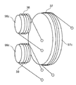
図4〜図9は、前記各コイル37〜39およびそれが巻回されるコア47〜49の構造を示す斜視図である。図4で示す構造では、1次側コア47aが、独立した複数の2次側のコア48a,49aとそれぞれ磁気回路を形成するために、1次側コア47aは同一方向に延びる一対の突起59,60を相反方向に2組備えたI字状に形成されており、これに対応して、2次側コア48a,49aは、同一方向に延びる一対の突起61,62を有するコの字状に形成され、それぞれの突起59,60;61,62が対向して磁気回路が形成される。前記突起59,60の断面積は突起61,62の断面積以上に形成され、高い磁気結合率を実現でき、伝送効率のよいシステムを実現できるようになっている。
4 to 9 are perspective views showing the structures of the
したがって、1次側の1つの出力端子コア47aを挟んで、両側に2次側の2つの負荷機器の入力端子コア48a,49aを配置した3段の積層構造となり、前記図1(b)および図2(b)で示すように、洗浄装置33と電気カミソリ32との間に給電プラグ36を挟み込めばよく、簡単かつコンパクトな構造で、2つの負荷機器に同時に電源供給を行うことができる。
Therefore, a three-stage laminated structure in which the
また、図5で示す構造では、2次側コア48b,49bが、3つの突起63,64を有するE字状に形成され、1次側コア47bも、前記E字型のコア48b,49bの突起63,64に対向して磁気回路を構成する複数の突起65,66を備えるコア形状を有する。このため、前記1次コイル37は、参照符号37a,37bで示す2つのコイルに分割されている。
Further, in the structure shown in FIG. 5, the
このように構成してもまた、1次側の1つの出力端子コア47bで2次側の2つの負荷機器の入力端子コア48b,49bと高い磁気結合率を実現できるとともに、3段の積層構造を実現することができる。
Even with this configuration, the single
さらにまた、図6で示す構造では、コア47c,48c,49cが、円柱または角柱状(図6では円柱)であり、各コイル37,38,39は、前記コア47c,48c,49cの外周面に巻回され、コア47c,48c,49cは一直線状に配列され、軸線方向の端面が相互に対向する。このように構成してもまた、1次側の1つの出力端子コア47cで2次側の2つの負荷機器の入力端子コア48c,49cと高い磁気結合率を実現できるとともに、3段の積層構造を実現することができる。
Furthermore, in the structure shown in FIG. 6, the
また、図7および図8で示す構造は、図5および図6で示す構造に類似しており、2次側の2つのコア48d,49dが、筒体67の一端を端板68で閉塞し、その端板68の中心に前記筒体67と同心の柱69を立設して成る、いわゆるポットコア形状であり、前記柱69にコイル38,39が巻回される。これに対応して、1次側のコア47dは、前記2次側のコア48d,49dを背中合わせに一体化した形状を有しており、柱69にコイル37が巻回される。したがって、筒体67および柱69の端面が対向することで、端板68を含めて磁気回路が形成される。コイル37,38,39が巻回される柱69は、筒体67で覆われているので、磁束の漏れが小さい。
The structure shown in FIGS. 7 and 8 is similar to the structure shown in FIGS. 5 and 6, and the two
このように構成してもまた、1次側の1つの出力端子コア47dで2次側の2つの負荷機器の入力端子コア48d,49dと高い磁気結合率を実現できるとともに、3段の積層構造を実現することができる。
Even with this configuration, the single
さらにまた、図9で示す構造では、1次側のコア47eは、長い円柱または角柱状(図9では円柱)であり、2次側の2つのコア48e,49eはリング状に形成され、その中心を前記コア47eの各端部が挿通する。2次側のコイル38,39は、コア48e,49eの外周面に巻回される。
Furthermore, in the structure shown in FIG. 9, the
このように構成してもまた、1次側の1つの出力端子コア47eで2次側の2つの負荷機器の入力端子コア48e,49eと高い磁気結合率を実現できるとともに、3段の積層構造を実現することができる。ただしこの構成では、ケーシング58,59には、1次側のコア47eが嵌り込む凹所が形成される。
Even with this configuration, the single
上述の図4〜図9で示すようなコアおよび巻線構造を用いることで、送電コイル37の両側に受電コイル38,39を近接配置した簡単かつコンパクトな3段の積層構造で、非接触の並列給電を可能とすることができる。これによって、洗浄装置33に電気カミソリ32を搭載した状態で電気カミソリ32に給電するにあたって、洗浄装置33にコンバータやインバータなどの電力変換手段を設ける必要はなくなり、構成を簡略化することもできる。
By using the core and winding structure as shown in FIG. 4 to FIG. 9 described above, a simple and compact three-stage laminated structure in which the power receiving coils 38 and 39 are arranged in close proximity on both sides of the
[実施の形態2]
図10は、本発明の実施の第2の形態に係る給電システムの構成を示す図である。この給電システムは、洗浄装置付き電気カミソリシステムであり、前述の図1および図2で示すシステムに類似し、対応する部分には同一の参照符号を付して示し、その説明を省略する。注目すべきは、本システムでは、図10(b)で示すように、洗浄装置73に電気カミソリ32が傾斜して配置されることに対応して、電源アダプタ71の給電プラグ76が楔型に形成されることである。なお、図2で示す電源アダプタ31aのように、コンバータ34と電圧共振型インバータ35との間が切離され、前記電線路40aによる直流送電となっていてもよい。
[Embodiment 2]
FIG. 10 is a diagram showing a configuration of a power feeding system according to the second embodiment of the present invention. This power supply system is an electric razor system with a cleaning device, and is similar to the system shown in FIG. 1 and FIG. 2 described above, and corresponding portions are denoted by the same reference numerals and description thereof is omitted. It should be noted that in this system, as shown in FIG. 10B, the
また、洗浄装置73には、前記洗浄用駆動回路43と並列に、電気カミソリ32の刃を誘導加熱で乾燥させる誘導加熱用コイル74が並列に接続されている。この誘導加熱用コイル74は、図示しないスイッチなどによって、前記洗浄用駆動回路43で駆動制御され、洗浄の終了した電気カミソリ32の刃を、前記AC50kHzの高周波で誘導加熱し、乾燥させる。
In addition, an
図11は、この給電プラグ76の送電コイル77および前記受電コイル38,39が巻回されるコア87a〜89aの構造を示す斜視図である。図11で示す構造では、1次側コア87aが、独立した2つの2次側のコア88a,89aとそれぞれ磁気回路を形成するために、1次側コア87aは同一方向に延びる一対の突起81,82を相互に直交する方向に2組備え、すなわち前記突起81,82は前記送電コイル77が巻回される軸部85の軸線方向から見てL字状に形成されており、これに対応して、2次側コア88a,89aは、前記図4で示す端子コア48a,49aと同様に、同一方向に延びる一対の突起83,84を有するコの字状に形成され、それぞれの突起81,82;83,84が対向して磁気回路が形成される。前記突起81,82の断面積は突起83,84の断面積以上に形成され、高い磁気結合率を実現でき、伝送効率のよいシステムを実現できるようになっている。
FIG. 11 is a perspective view showing the structure of the
したがって、1次側の1つの出力端子コア87aを挟んで、軸線方向から見てL字状に2次側の2つの負荷機器の入力端子コア88a,89aを配置したL字構造となり、前記図10(b)で示すように、洗浄装置73に電気カミソリ32が傾斜を有して配置される場合に、それぞれに内蔵される2次コア88a,89aに対して、1次コア87aは密着することができる。
Accordingly, an L-shaped structure is formed in which the
図12は、前記給電プラグ76の送電コイル77および前記受電コイル38,39が巻回される他のコア87b〜89bの構造を示す斜視図である。図11で示す構造において、2次側のコア88b,89bは、前述のコア88a,89aと同一である。注目すべきは、本実施の形態では、1次側コア87bはボビン状に形成され、前記2次側コア88a,89aのコ字の両端部の突起83,84が、前記1次側コア87bのボビンのフランジ87cにそれぞれ対向し、前記コ字状の2次側のコア88b,89bは前記1次側コア87bの周方向に複数配置されることで、対応する負荷機器に同時に給電可能となることである。
FIG. 12 is a perspective view showing a structure of
このように磁路を形成するために1次側コア87bから2次側コア88b,89bに向けて延びる突起をボビンのフランジとすることで、2次側コア88b,89bはコ字状として1次側コア87bの周囲に配置するだけで磁路が形成され、前記コ字の中央部に巻回される受電コイル38,39の径などに応じた数だけ、2次側コアを配置することができる(図12では、参照符号90bで示す2次側コアを含めて3つ)。
Thus, in order to form a magnetic path, the protrusion extending from the
上述の図11および図12で示すようなコアおよび巻線構造を用いることで、送電コイル37の両側に受電コイル38,39を近接配置した簡単かつコンパクトなL字構造で、傾斜を有して配置される2つの負荷機器に、非接触の並列給電を可能とすることができる。
By using the core and winding structure as shown in FIG. 11 and FIG. 12 described above, a simple and compact L-shaped structure in which the power receiving coils 38 and 39 are disposed close to both sides of the
[実施の形態3]
図13〜図15は、本発明の実施の第3の形態に係る給電システムにおける送電コイル37および受電コイル38,39が巻回されるコア97a〜99a;97b〜99b;97c〜99cの構造をそれぞれ示す斜視図である。各コア97a〜99a;97b〜99b;97c〜99cで注目すべきは、送電コイル37が巻回されるコア97a,97b,97cの一方側に、受電コイル38,39が巻回されるコア98a,98b,98c;99a,99b,99cが配置されることである。
[Embodiment 3]
FIGS. 13 to 15 show the structures of the
図13で示すコア97a,98a,99aでは、2次側コア98a,99aは、前述の図5で示す2次側コア48b,49bと同様にE字状のコアである、1次側コア97aは、それらを一方側に長手(縦)方向に配列した状態で対向するように、前記E字状のコアを2段長手方向に連結した構造となっている。このため、送電コイル37は、2つのコイル37a,37bに分離されている。1次側コア97aの対向部の断面積は、2次側コア98a,99aの対向部の断面積の総和と同等以上に形成されている。
In the
また、図14で示すコア97b,98b,99bでも、2次側コア98b,99bは、前述の2次側コア48b,49b;98a,99aと同様にE字状のコアであり、1次側コア97bが、それらを一方側に厚み(横)方向に配列した状態で対向するように、前記E字状のコアを2段厚み方向に連結した構造となっている。1次側コア97bの対向部の断面積は、2次側コア98b,99bの対向部の断面積の総和と同等以上に形成されている。
Also, in the
さらにまた、図15で示すコア97c,98c,99cでは、2次側コア98c,99cは、前述の図6で示す2次側コア48c,49cと同様に円柱または角柱(図15では円柱)状のコアであり、1次側からの磁束を2次側のコイル38,39に交錯させることで電力伝達を行う。ただし、1次側コア97cは、それらを一方側に並列(横)に配列した状態で対向するように、円盤状に形成されている。
Furthermore, in the
これら図13〜図15で示す構造を用いた場合、2つの負荷機器が並列配置される場合に好適に、電力伝送を行うことができる。 When these structures shown in FIGS. 13 to 15 are used, it is possible to perform power transmission suitably when two load devices are arranged in parallel.
[実施の形態4]
図16は、本発明の実施の第4の形態に係る給電システムにおける送電コイル37および受電コイル38,39が巻回されるコア107〜109の構造を示す斜視図である。注目すべきは、本実施の形態では、各コイル37〜39がそれぞれコ字状のコア107〜109に巻回され、そのコア107〜109が、コ字の上方または下方から見て、120°の等間隔に配置されることである。このように構成してもまた、1つの送電コイル37から2つの受電コイル38,39へ均等に電力伝達を行うことができる。
[Embodiment 4]
FIG. 16 is a perspective view showing a structure of
なお、本発明は、電源装置の高周波電線路に通電された高周波の電圧と同じ周波数の電圧が特定の電気機器の電線路に通電されていることを特徴とする給電システムであるが、電圧と電流との関係が、インピーダンスを介して関係づけられていることから、電源装置のインバータの出力が等価的に高周波電流源を構成する場合には、特定の電気機器の電線路には同じ周波数の電流が流れていることも本発明と同一の範疇であることはもちろんである。さらに、本発明は、複数の特定の電気機器に同時に並列給電を行えるシステムであるから、特定の電気機器の入力端子には高周波の交流電圧が生じるが、特定の電気機器の内部にて、この入力端子につながる電線路あるいは回路上には、通電を制御する電子スイッチあるいは機械スイッチ、変換回路等が含まれ、機器内部での給電制御の可能な構成が含まれることはもちろんである。 The present invention is a power supply system characterized in that a voltage having the same frequency as the high-frequency voltage supplied to the high-frequency electric line of the power supply device is supplied to the electric line of the specific electrical device. Since the relationship with the current is related via the impedance, when the output of the inverter of the power supply device equivalently constitutes a high-frequency current source, the electric wire of a specific electric device has the same frequency. It goes without saying that a current is flowing in the same category as the present invention. Furthermore, since the present invention is a system that can simultaneously supply power to a plurality of specific electrical devices at the same time, a high-frequency AC voltage is generated at the input terminal of the specific electrical device. The electric line or circuit connected to the input terminal includes an electronic switch or mechanical switch for controlling energization, a conversion circuit, and the like, and of course includes a configuration capable of controlling power feeding inside the device.
[実施の形態5]
図17および図18は、本発明の実施の第5の形態に係る給電システムの構成を示す図である。この給電システムも、洗浄装置付き電気カミソリシステムであり、前述の図1〜図3ならびに図10で示すシステムに類似し、対応する部分には同一の参照符号を付して示し、その説明を省略する。本実施の形態では、図19でも示すように、電源アダプタ101の給電プラグ106において、前記送電コイル37は電気カミソリ32用の1次側コア107に巻回されており、洗浄装置103,103’用に送電用の金属接点102が併用される。図17の洗浄装置103と、図18の洗浄装置103’とは、前記誘導加熱用コイル73が設けられているか否かが異なる。
[Embodiment 5]
17 and 18 are diagrams showing the configuration of the power feeding system according to the fifth embodiment of the present invention. This power supply system is also an electric razor system with a cleaning device, which is similar to the system shown in FIG. 1 to FIG. 3 and FIG. 10 described above, and corresponding parts are denoted by the same reference numerals and description thereof is omitted. To do. In the present embodiment, as shown in FIG. 19, in the
これに対応して、洗浄装置103,103’には、受電用の金属接点104が設けられている。前記金属接点102,104は、耐食性に優れた材料から成る。このようにAC50kHzの電線路40を用いることで、意匠面で金属接点が露出しない方が好ましい電気カミソリ32に非接触で給電を行い、消費電力が大きく、損失を抑制したい洗浄装置103,103’に、接触式で給電を行うようにしてもよい。また、接触式の給電は、安価である。
Correspondingly, the
[実施の形態6]
図20は、本発明の実施の第6の形態に係る給電システムの構成を示す図である。この給電システムも、洗浄装置付き電気カミソリシステムであり、前述の図10で示すシステムに類似し、対応する部分には同一の参照符号を付して示し、その説明を省略する。本実施の形態では、電気カミソリ112および洗浄装置113において、2次コイルとなる受電コイル118,119は、コア持たない構成となっている。したがって、リング状に巻回される受電コイル118,119内に、電源アダプタ111の給電プラグ116の送電コイル117が嵌込する。
[Embodiment 6]
FIG. 20 is a diagram showing a configuration of a power feeding system according to the sixth embodiment of the present invention. This power supply system is also an electric razor system with a cleaning device, which is similar to the system shown in FIG. 10 described above, and corresponding portions are denoted by the same reference numerals and description thereof is omitted. In the present embodiment, in the
31,31a,101,111 電源アダプタ
32,112 電気カミソリ
33,73,103,103’,113 洗浄装置
34 コンバータ
35 電圧共振型インバータ
36,76,116 給電プラグ
37,37a,37b,77,117 送電コイル
38,39,118,119 受電コイル
40,40a 電線路
41 負荷回路
42 降圧電源
47,47a,47b,47c,47d,47e 1次側コア
48,48a,48b,48c,48d,48e 2次側コア
49,49a,49b,49c,49d,49e 2次側コア
51,53,55,57 コンバータ
52,54,56,58 負荷回路
59a スロット
59b,59c ケーシング
59,60;61,62;63,64;65,66;81,82;83,84 突起
67 筒体
68 端板
69 柱
74 誘導加熱用コイル
87a,87b,97a,97b,97c,107 1次側コア
88a,88b,98a,98b,98c,108 2次側コア
89a,89b,99a,99b,99c,109 2次側コア
87c フランジ
90b 2次側コア
102,104 金属接点
31, 31a, 101, 111
Claims (3)
前記電源アダプタは、高周波交流を、その出力端子となり、1次コアに巻回された1次コイルから出力し、
前記負荷機器は、各負荷機器間で同時に前記1次コアと閉磁路を形成可能な2次コアをそれぞれ有し、その2次コアに巻回された2次コイルから給電出力を取出すにあたって、
前記1次コアは、1次コイルが巻回される軸部の両端部から同一方向に延びる一対の突起を、相互に直交する方向に2組備え、前記2次コアは、同一方向に延びる一対の突起を備え、前記軸部の軸線方向から見て、1次コアに対して、L字状となるように2次コアを配置することで、2つの負荷機器に同時に給電可能とすることを特徴とする給電システム。 In a power supply system that enables power supply from a power adapter to multiple load devices,
The power adapter outputs high-frequency alternating current from a primary coil wound around a primary core as its output terminal,
The load device has a secondary core capable of forming a closed magnetic circuit with the primary core at the same time between the load devices, and when taking out a power supply output from a secondary coil wound around the secondary core ,
The primary core includes two pairs of protrusions extending in the same direction from both ends of the shaft around which the primary coil is wound, and the secondary core is a pair extending in the same direction. By arranging the secondary core so as to be L-shaped with respect to the primary core when viewed from the axial direction of the shaft portion, power can be supplied to two load devices at the same time. Characteristic power supply system.
前記電源アダプタは、高周波交流を、その出力端子となり、1次コアに巻回された1次コイルから出力し、
前記負荷機器は、各負荷機器間で同時に前記1次コアと閉磁路を形成可能な2次コアをそれぞれ有し、その2次コアに巻回された2次コイルから給電出力を取出すにあたって、
前記1次コアはボビン状に形成され、前記2次コアはコ字状に形成され、前記2次コアのコ字の両端部が、前記1次コアのボビンのフランジにそれぞれ対向し、前記コ字状の2次コアは前記1次コアの周方向に複数配置されることで、対応する負荷機器に同時に給電可能となることを特徴とする給電システム。 In a power supply system that enables power supply from a power adapter to multiple load devices,
The power adapter outputs high-frequency alternating current from a primary coil wound around a primary core as its output terminal,
The load device has a secondary core capable of forming a closed magnetic circuit with the primary core at the same time between the load devices, and when taking out a power supply output from a secondary coil wound around the secondary core,
The primary core is formed in a bobbin shape, the secondary core is formed in a U shape, and both end portions of the U shape of the secondary core are respectively opposed to flanges of the bobbin of the primary core, by-shaped secondary cores are more arranged in the circumferential direction of the primary core, the sheet collector system that is characterized in that the power can be supplied to the corresponding load devices simultaneously.
Priority Applications (5)
| Application Number | Priority Date | Filing Date | Title |
|---|---|---|---|
| JP2005311087A JP4852970B2 (en) | 2005-10-26 | 2005-10-26 | Power supply system |
| EP06022179A EP1780862A3 (en) | 2005-10-26 | 2006-10-23 | Power supply system |
| US11/585,219 US7514818B2 (en) | 2005-10-26 | 2006-10-24 | Power supply system |
| CNU200620157110XU CN201001086Y (en) | 2005-10-26 | 2006-10-25 | Electricity supply system |
| CNA2006101365573A CN1960151A (en) | 2005-10-26 | 2006-10-25 | Power supply system |
Applications Claiming Priority (1)
| Application Number | Priority Date | Filing Date | Title |
|---|---|---|---|
| JP2005311087A JP4852970B2 (en) | 2005-10-26 | 2005-10-26 | Power supply system |
Publications (2)
| Publication Number | Publication Date |
|---|---|
| JP2007124754A JP2007124754A (en) | 2007-05-17 |
| JP4852970B2 true JP4852970B2 (en) | 2012-01-11 |
Family
ID=37680578
Family Applications (1)
| Application Number | Title | Priority Date | Filing Date |
|---|---|---|---|
| JP2005311087A Expired - Fee Related JP4852970B2 (en) | 2005-10-26 | 2005-10-26 | Power supply system |
Country Status (4)
| Country | Link |
|---|---|
| US (1) | US7514818B2 (en) |
| EP (1) | EP1780862A3 (en) |
| JP (1) | JP4852970B2 (en) |
| CN (2) | CN1960151A (en) |
Families Citing this family (116)
| Publication number | Priority date | Publication date | Assignee | Title |
|---|---|---|---|---|
| US7825543B2 (en) | 2005-07-12 | 2010-11-02 | Massachusetts Institute Of Technology | Wireless energy transfer |
| AU2006269374C1 (en) * | 2005-07-12 | 2010-03-25 | Massachusetts Institute Of Technology | Wireless non-radiative energy transfer |
| US8805530B2 (en) | 2007-06-01 | 2014-08-12 | Witricity Corporation | Power generation for implantable devices |
| US9421388B2 (en) | 2007-06-01 | 2016-08-23 | Witricity Corporation | Power generation for implantable devices |
| US7960867B2 (en) * | 2007-11-27 | 2011-06-14 | Extremely Ingenious Engineering | Methods and systems for wireless energy and data transmission |
| WO2009140506A1 (en) * | 2008-05-14 | 2009-11-19 | Massachusetts Institute Of Technology | Wireless energy transfer, including interference enhancement |
| US8928276B2 (en) | 2008-09-27 | 2015-01-06 | Witricity Corporation | Integrated repeaters for cell phone applications |
| US8324759B2 (en) | 2008-09-27 | 2012-12-04 | Witricity Corporation | Wireless energy transfer using magnetic materials to shape field and reduce loss |
| US8400017B2 (en) | 2008-09-27 | 2013-03-19 | Witricity Corporation | Wireless energy transfer for computer peripheral applications |
| KR101789904B1 (en) | 2008-09-27 | 2017-10-25 | 위트리시티 코포레이션 | Wireless energy transfer systems |
| US9601270B2 (en) | 2008-09-27 | 2017-03-21 | Witricity Corporation | Low AC resistance conductor designs |
| US8937408B2 (en) | 2008-09-27 | 2015-01-20 | Witricity Corporation | Wireless energy transfer for medical applications |
| US8901779B2 (en) | 2008-09-27 | 2014-12-02 | Witricity Corporation | Wireless energy transfer with resonator arrays for medical applications |
| US8692410B2 (en) | 2008-09-27 | 2014-04-08 | Witricity Corporation | Wireless energy transfer with frequency hopping |
| US9106203B2 (en) | 2008-09-27 | 2015-08-11 | Witricity Corporation | Secure wireless energy transfer in medical applications |
| US9601261B2 (en) | 2008-09-27 | 2017-03-21 | Witricity Corporation | Wireless energy transfer using repeater resonators |
| US8304935B2 (en) | 2008-09-27 | 2012-11-06 | Witricity Corporation | Wireless energy transfer using field shaping to reduce loss |
| US9544683B2 (en) | 2008-09-27 | 2017-01-10 | Witricity Corporation | Wirelessly powered audio devices |
| US9246336B2 (en) | 2008-09-27 | 2016-01-26 | Witricity Corporation | Resonator optimizations for wireless energy transfer |
| US8947186B2 (en) | 2008-09-27 | 2015-02-03 | Witricity Corporation | Wireless energy transfer resonator thermal management |
| US8471410B2 (en) | 2008-09-27 | 2013-06-25 | Witricity Corporation | Wireless energy transfer over distance using field shaping to improve the coupling factor |
| US8901778B2 (en) | 2008-09-27 | 2014-12-02 | Witricity Corporation | Wireless energy transfer with variable size resonators for implanted medical devices |
| US8669676B2 (en) | 2008-09-27 | 2014-03-11 | Witricity Corporation | Wireless energy transfer across variable distances using field shaping with magnetic materials to improve the coupling factor |
| US9184595B2 (en) | 2008-09-27 | 2015-11-10 | Witricity Corporation | Wireless energy transfer in lossy environments |
| US8552592B2 (en) | 2008-09-27 | 2013-10-08 | Witricity Corporation | Wireless energy transfer with feedback control for lighting applications |
| US9105959B2 (en) | 2008-09-27 | 2015-08-11 | Witricity Corporation | Resonator enclosure |
| US9065423B2 (en) | 2008-09-27 | 2015-06-23 | Witricity Corporation | Wireless energy distribution system |
| US8461720B2 (en) | 2008-09-27 | 2013-06-11 | Witricity Corporation | Wireless energy transfer using conducting surfaces to shape fields and reduce loss |
| US8629578B2 (en) | 2008-09-27 | 2014-01-14 | Witricity Corporation | Wireless energy transfer systems |
| US9318922B2 (en) | 2008-09-27 | 2016-04-19 | Witricity Corporation | Mechanically removable wireless power vehicle seat assembly |
| US9093853B2 (en) | 2008-09-27 | 2015-07-28 | Witricity Corporation | Flexible resonator attachment |
| US8963488B2 (en) | 2008-09-27 | 2015-02-24 | Witricity Corporation | Position insensitive wireless charging |
| US8686598B2 (en) | 2008-09-27 | 2014-04-01 | Witricity Corporation | Wireless energy transfer for supplying power and heat to a device |
| US8441154B2 (en) | 2008-09-27 | 2013-05-14 | Witricity Corporation | Multi-resonator wireless energy transfer for exterior lighting |
| US8933594B2 (en) | 2008-09-27 | 2015-01-13 | Witricity Corporation | Wireless energy transfer for vehicles |
| US8497601B2 (en) | 2008-09-27 | 2013-07-30 | Witricity Corporation | Wireless energy transfer converters |
| US9035499B2 (en) | 2008-09-27 | 2015-05-19 | Witricity Corporation | Wireless energy transfer for photovoltaic panels |
| US9601266B2 (en) | 2008-09-27 | 2017-03-21 | Witricity Corporation | Multiple connected resonators with a single electronic circuit |
| US8643326B2 (en) | 2008-09-27 | 2014-02-04 | Witricity Corporation | Tunable wireless energy transfer systems |
| US8461721B2 (en) * | 2008-09-27 | 2013-06-11 | Witricity Corporation | Wireless energy transfer using object positioning for low loss |
| US8772973B2 (en) | 2008-09-27 | 2014-07-08 | Witricity Corporation | Integrated resonator-shield structures |
| US8912687B2 (en) | 2008-09-27 | 2014-12-16 | Witricity Corporation | Secure wireless energy transfer for vehicle applications |
| US9744858B2 (en) | 2008-09-27 | 2017-08-29 | Witricity Corporation | System for wireless energy distribution in a vehicle |
| US8461722B2 (en) | 2008-09-27 | 2013-06-11 | Witricity Corporation | Wireless energy transfer using conducting surfaces to shape field and improve K |
| US8410636B2 (en) | 2008-09-27 | 2013-04-02 | Witricity Corporation | Low AC resistance conductor designs |
| US9515494B2 (en) | 2008-09-27 | 2016-12-06 | Witricity Corporation | Wireless power system including impedance matching network |
| US8569914B2 (en) | 2008-09-27 | 2013-10-29 | Witricity Corporation | Wireless energy transfer using object positioning for improved k |
| US8476788B2 (en) | 2008-09-27 | 2013-07-02 | Witricity Corporation | Wireless energy transfer with high-Q resonators using field shaping to improve K |
| US8957549B2 (en) | 2008-09-27 | 2015-02-17 | Witricity Corporation | Tunable wireless energy transfer for in-vehicle applications |
| US8723366B2 (en) | 2008-09-27 | 2014-05-13 | Witricity Corporation | Wireless energy transfer resonator enclosures |
| US8482158B2 (en) | 2008-09-27 | 2013-07-09 | Witricity Corporation | Wireless energy transfer using variable size resonators and system monitoring |
| US8487480B1 (en) * | 2008-09-27 | 2013-07-16 | Witricity Corporation | Wireless energy transfer resonator kit |
| US9577436B2 (en) | 2008-09-27 | 2017-02-21 | Witricity Corporation | Wireless energy transfer for implantable devices |
| US9160203B2 (en) | 2008-09-27 | 2015-10-13 | Witricity Corporation | Wireless powered television |
| US9396867B2 (en) | 2008-09-27 | 2016-07-19 | Witricity Corporation | Integrated resonator-shield structures |
| US8922066B2 (en) | 2008-09-27 | 2014-12-30 | Witricity Corporation | Wireless energy transfer with multi resonator arrays for vehicle applications |
| US8598743B2 (en) | 2008-09-27 | 2013-12-03 | Witricity Corporation | Resonator arrays for wireless energy transfer |
| US8587155B2 (en) | 2008-09-27 | 2013-11-19 | Witricity Corporation | Wireless energy transfer using repeater resonators |
| US8466583B2 (en) | 2008-09-27 | 2013-06-18 | Witricity Corporation | Tunable wireless energy transfer for outdoor lighting applications |
| US8587153B2 (en) | 2008-09-27 | 2013-11-19 | Witricity Corporation | Wireless energy transfer using high Q resonators for lighting applications |
| US8692412B2 (en) | 2008-09-27 | 2014-04-08 | Witricity Corporation | Temperature compensation in a wireless transfer system |
| US8907531B2 (en) | 2008-09-27 | 2014-12-09 | Witricity Corporation | Wireless energy transfer with variable size resonators for medical applications |
| US8946938B2 (en) | 2008-09-27 | 2015-02-03 | Witricity Corporation | Safety systems for wireless energy transfer in vehicle applications |
| EP2345100B1 (en) | 2008-10-01 | 2018-12-05 | Massachusetts Institute of Technology | Efficient near-field wireless energy transfer using adiabatic system variations |
| WO2010067927A1 (en) | 2008-12-12 | 2010-06-17 | Jung Chun-Kil | Contactless charging station equipped with a ptps core having a planar spiral core structure, contactless power receiving apparatus, and method for controlling same |
| EP2528194A4 (en) * | 2010-01-21 | 2017-08-30 | Sharp Kabushiki Kaisha | Contactless electricity-supplying device |
| EP2393181B1 (en) * | 2010-06-02 | 2019-09-04 | FRIWO Gerätebau GmbH | Circuit for a system for a contactless, inductive energy transfer |
| US9602168B2 (en) | 2010-08-31 | 2017-03-21 | Witricity Corporation | Communication in wireless energy transfer systems |
| US9948145B2 (en) | 2011-07-08 | 2018-04-17 | Witricity Corporation | Wireless power transfer for a seat-vest-helmet system |
| AU2012289855A1 (en) | 2011-08-04 | 2014-03-13 | Witricity Corporation | Tunable wireless power architectures |
| WO2013036947A2 (en) | 2011-09-09 | 2013-03-14 | Witricity Corporation | Foreign object detection in wireless energy transfer systems |
| US20130062966A1 (en) | 2011-09-12 | 2013-03-14 | Witricity Corporation | Reconfigurable control architectures and algorithms for electric vehicle wireless energy transfer systems |
| US9318257B2 (en) | 2011-10-18 | 2016-04-19 | Witricity Corporation | Wireless energy transfer for packaging |
| HK1200602A1 (en) | 2011-11-04 | 2015-08-07 | WiTricity公司 | Wireless energy transfer modeling tool |
| WO2013113017A1 (en) | 2012-01-26 | 2013-08-01 | Witricity Corporation | Wireless energy transfer with reduced fields |
| US20130328407A1 (en) * | 2012-06-08 | 2013-12-12 | Canon Kabushiki Kaisha | Wireless power transmission apparatus, wireless power transmission system, and wireless communication apparatus |
| US9105958B2 (en) | 2012-06-11 | 2015-08-11 | Live Longer, LLC | Pseudo-antenna and system and method for manufacture of the same |
| US9343922B2 (en) | 2012-06-27 | 2016-05-17 | Witricity Corporation | Wireless energy transfer for rechargeable batteries |
| US9287607B2 (en) | 2012-07-31 | 2016-03-15 | Witricity Corporation | Resonator fine tuning |
| US9595378B2 (en) | 2012-09-19 | 2017-03-14 | Witricity Corporation | Resonator enclosure |
| US9404954B2 (en) | 2012-10-19 | 2016-08-02 | Witricity Corporation | Foreign object detection in wireless energy transfer systems |
| US9449757B2 (en) | 2012-11-16 | 2016-09-20 | Witricity Corporation | Systems and methods for wireless power system with improved performance and/or ease of use |
| JP6010491B2 (en) * | 2013-03-15 | 2016-10-19 | 株式会社東芝 | Resonator and wireless power transmission device |
| US9857821B2 (en) | 2013-08-14 | 2018-01-02 | Witricity Corporation | Wireless power transfer frequency adjustment |
| US10277080B2 (en) | 2014-01-27 | 2019-04-30 | Cummins Inc. | Inductive harness coupling and communication for distributed architectures |
| US9780573B2 (en) | 2014-02-03 | 2017-10-03 | Witricity Corporation | Wirelessly charged battery system |
| WO2015123614A2 (en) | 2014-02-14 | 2015-08-20 | Witricity Corporation | Object detection for wireless energy transfer systems |
| JP6375386B2 (en) * | 2014-03-14 | 2018-08-15 | コーニンクレッカ フィリップス エヌ ヴェKoninklijke Philips N.V. | Electric shaver |
| US9892849B2 (en) | 2014-04-17 | 2018-02-13 | Witricity Corporation | Wireless power transfer systems with shield openings |
| US9842687B2 (en) | 2014-04-17 | 2017-12-12 | Witricity Corporation | Wireless power transfer systems with shaped magnetic components |
| US9837860B2 (en) | 2014-05-05 | 2017-12-05 | Witricity Corporation | Wireless power transmission systems for elevators |
| EP3140680B1 (en) | 2014-05-07 | 2021-04-21 | WiTricity Corporation | Foreign object detection in wireless energy transfer systems |
| WO2015196123A2 (en) | 2014-06-20 | 2015-12-23 | Witricity Corporation | Wireless power transfer systems for surfaces |
| US10574091B2 (en) | 2014-07-08 | 2020-02-25 | Witricity Corporation | Enclosures for high power wireless power transfer systems |
| WO2016007674A1 (en) | 2014-07-08 | 2016-01-14 | Witricity Corporation | Resonator balancing in wireless power transfer systems |
| US9843217B2 (en) | 2015-01-05 | 2017-12-12 | Witricity Corporation | Wireless energy transfer for wearables |
| US9912172B2 (en) * | 2015-01-14 | 2018-03-06 | Qualcomm Incorporated | Asymmetrically layered stacked coils and/or chamfered ferrite in wireless power transfer applications |
| CN107206916B (en) * | 2015-02-06 | 2021-04-06 | 柿子技术公司 | Movable power coupling and robot with movable power coupling |
| DE102015005921A1 (en) * | 2015-05-07 | 2016-11-10 | Samson Aktiengesellschaft | Controller without auxiliary power |
| CN105098897A (en) * | 2015-07-30 | 2015-11-25 | 京东方科技集团股份有限公司 | Wearable device and terminal |
| JP6714076B2 (en) * | 2015-09-03 | 2020-06-24 | コーニンクレッカ フィリップス エヌ ヴェKoninklijke Philips N.V. | Stackable connectors and devices for wireless transmission of power |
| US10248899B2 (en) | 2015-10-06 | 2019-04-02 | Witricity Corporation | RFID tag and transponder detection in wireless energy transfer systems |
| JP2018538517A (en) | 2015-10-14 | 2018-12-27 | ワイトリシティ コーポレーションWitricity Corporation | Phase and amplitude detection in wireless energy transfer systems |
| WO2017070227A1 (en) | 2015-10-19 | 2017-04-27 | Witricity Corporation | Foreign object detection in wireless energy transfer systems |
| EP3365958B1 (en) | 2015-10-22 | 2020-05-27 | WiTricity Corporation | Dynamic tuning in wireless energy transfer systems |
| US10075019B2 (en) | 2015-11-20 | 2018-09-11 | Witricity Corporation | Voltage source isolation in wireless power transfer systems |
| CN106887906B (en) * | 2015-12-16 | 2024-06-18 | 泰科电子(上海)有限公司 | Wireless power supply device and electrical equipment |
| US20170214269A1 (en) * | 2016-01-22 | 2017-07-27 | Boston Scientific Neuromodulation Corporation | Physically-Configurable External Charger for an Implantable Medical Device with Receptacle in Coil Housing for Electronics Module |
| CA3012325A1 (en) | 2016-02-02 | 2017-08-10 | Witricity Corporation | Controlling wireless power transfer systems |
| JP6888017B2 (en) | 2016-02-08 | 2021-06-16 | ワイトリシティ コーポレーションWitricity Corporation | PWM capacitor control |
| JP6635306B2 (en) * | 2016-09-21 | 2020-01-22 | 株式会社オートネットワーク技術研究所 | Magnetic core for reactors and reactors |
| JP2019009161A (en) * | 2017-06-21 | 2019-01-17 | トヨタ自動車株式会社 | Coil unit |
| EP3646434B1 (en) | 2017-06-29 | 2025-01-22 | Witricity Corporation | Protection and control of wireless power systems |
| US11049642B1 (en) * | 2017-09-26 | 2021-06-29 | Universal Lighting Technologies, Inc. | Dual magnetic component with three core portions |
| CN110308322B (en) * | 2019-06-29 | 2021-07-23 | 杭州涂鸦信息技术有限公司 | Method for calculating electric quantity of power adapter |
| US20250112488A1 (en) * | 2023-09-29 | 2025-04-03 | Apple Inc. | Ac power delivery for reduced corrosion |
Family Cites Families (16)
| Publication number | Priority date | Publication date | Assignee | Title |
|---|---|---|---|---|
| JP2832546B2 (en) | 1989-09-13 | 1998-12-09 | 三菱電機株式会社 | Electromagnetic outlet device |
| JPH0451505A (en) * | 1990-06-19 | 1992-02-20 | Ko Nanbu | Connector |
| JPH06189479A (en) * | 1992-12-15 | 1994-07-08 | Toyota Autom Loom Works Ltd | Electromagnetic power feeding apparatus |
| JPH06225482A (en) * | 1993-01-26 | 1994-08-12 | Matsushita Electric Works Ltd | Power feeding apparatus |
| US5680028A (en) * | 1994-06-30 | 1997-10-21 | Mceachern; Alexander | Charger for hand-held rechargeable electric apparatus with reduced magnetic field |
| US5889384A (en) * | 1997-02-20 | 1999-03-30 | Ericsson Inc. | Power transfer and voltage level conversion for a battery-powered electronic device |
| JPH10270273A (en) | 1997-03-25 | 1998-10-09 | Hitachi Cable Ltd | Dischargeable detachable power supply method |
| CN2304177Y (en) | 1997-08-08 | 1999-01-13 | 王月明 | Cross-flux voltage regulator |
| DE19921677A1 (en) * | 1999-05-18 | 2000-11-23 | Braun Gmbh | Additional device for a small electrical device and method for detecting an electrical and / or magnetic connection between the devices |
| AU4926600A (en) * | 1999-06-11 | 2001-01-02 | Abb Research Ltd | System for a machine with a plurality of proximity sensors and a proximity sensor and a primary winding used in such machine |
| JP2002043151A (en) * | 2000-07-25 | 2002-02-08 | Matsushita Electric Works Ltd | Non-contact charge transformer, and manufacturing method of rechargeable electrical apparatus |
| JP2002110437A (en) * | 2000-09-29 | 2002-04-12 | Toko Inc | Power supply |
| GB0026369D0 (en) * | 2000-10-27 | 2000-12-13 | Microlights Ltd | Improvements in and relating to an electrical lighting system |
| JP4092895B2 (en) * | 2001-08-28 | 2008-05-28 | 松下電工株式会社 | Contactless power supply equipment |
| DE10225005C1 (en) * | 2002-06-06 | 2003-12-04 | Wampfler Ag | Inductive energy transmission device for moving load with inductive coupling used for energy transfer between successive conductor path sections |
| GB2416248B (en) * | 2003-05-02 | 2007-02-21 | George Alan Limpkin | Apparatus for supplying energy to a load and a related system |
-
2005
- 2005-10-26 JP JP2005311087A patent/JP4852970B2/en not_active Expired - Fee Related
-
2006
- 2006-10-23 EP EP06022179A patent/EP1780862A3/en not_active Withdrawn
- 2006-10-24 US US11/585,219 patent/US7514818B2/en not_active Expired - Fee Related
- 2006-10-25 CN CNA2006101365573A patent/CN1960151A/en active Pending
- 2006-10-25 CN CNU200620157110XU patent/CN201001086Y/en not_active Expired - Fee Related
Also Published As
| Publication number | Publication date |
|---|---|
| US20070091519A1 (en) | 2007-04-26 |
| CN1960151A (en) | 2007-05-09 |
| EP1780862A3 (en) | 2009-04-01 |
| US7514818B2 (en) | 2009-04-07 |
| CN201001086Y (en) | 2008-01-02 |
| JP2007124754A (en) | 2007-05-17 |
| EP1780862A2 (en) | 2007-05-02 |
Similar Documents
| Publication | Publication Date | Title |
|---|---|---|
| JP4852970B2 (en) | Power supply system | |
| CN102144347B (en) | Induction electricity charger and charging method | |
| KR100888465B1 (en) | Inductive coupling system with capacitive parallel compensation of mutual magnetic inductance between primary and secondary windings, and combination of rechargeable electrical appliances and stand | |
| JP4258505B2 (en) | Power supply system | |
| CN107222031B (en) | Power supply device and wireless power transmission device | |
| JPH08280139A (en) | Management of heat using geometric arrangement of hybrid spiral/helical coil | |
| JP2002010535A (en) | Non-contact power transmission device | |
| JP2846090B2 (en) | Non-contact type transformer | |
| CN106505643A (en) | Noncontact power supply device | |
| JPH1198707A (en) | Contactless charging device | |
| WO2014115223A1 (en) | Contactless power transmission system | |
| JP6167413B2 (en) | Non-contact power transmission system | |
| JP5384195B2 (en) | Non-contact power supply device | |
| JP3330222B2 (en) | Non-contact power transmission device | |
| JPH07106170A (en) | Transformer for noncontact-type charger | |
| JP5984106B2 (en) | Non-contact power transmission device | |
| TW438952B (en) | Microwave oven | |
| JP7378084B2 (en) | Contactless power transfer system | |
| US10084351B2 (en) | Power feeding device | |
| WO2014115215A1 (en) | Noncontact charger | |
| JPS63253836A (en) | Power transmitter | |
| JP7422554B2 (en) | Contactless power transfer system | |
| JP2011066081A (en) | Transformer, switching device and converter | |
| JP2017184439A (en) | Wireless power transmission coil, wireless power supply system, wireless power reception system and wireless power transmission system |
Legal Events
| Date | Code | Title | Description |
|---|---|---|---|
| A621 | Written request for application examination |
Free format text: JAPANESE INTERMEDIATE CODE: A621 Effective date: 20070613 |
|
| A977 | Report on retrieval |
Free format text: JAPANESE INTERMEDIATE CODE: A971007 Effective date: 20100308 |
|
| A131 | Notification of reasons for refusal |
Free format text: JAPANESE INTERMEDIATE CODE: A131 Effective date: 20100413 |
|
| A521 | Request for written amendment filed |
Free format text: JAPANESE INTERMEDIATE CODE: A523 Effective date: 20100614 |
|
| A131 | Notification of reasons for refusal |
Free format text: JAPANESE INTERMEDIATE CODE: A131 Effective date: 20110329 |
|
| TRDD | Decision of grant or rejection written | ||
| A01 | Written decision to grant a patent or to grant a registration (utility model) |
Free format text: JAPANESE INTERMEDIATE CODE: A01 Effective date: 20110927 |
|
| A01 | Written decision to grant a patent or to grant a registration (utility model) |
Free format text: JAPANESE INTERMEDIATE CODE: A01 |
|
| A61 | First payment of annual fees (during grant procedure) |
Free format text: JAPANESE INTERMEDIATE CODE: A61 Effective date: 20111010 |
|
| FPAY | Renewal fee payment (event date is renewal date of database) |
Free format text: PAYMENT UNTIL: 20141104 Year of fee payment: 3 |
|
| R150 | Certificate of patent or registration of utility model |
Free format text: JAPANESE INTERMEDIATE CODE: R150 |
|
| LAPS | Cancellation because of no payment of annual fees |