JP4837279B2 - Epi-illumination microscope and fluorescent filter set - Google Patents
Epi-illumination microscope and fluorescent filter set Download PDFInfo
- Publication number
- JP4837279B2 JP4837279B2 JP2004355747A JP2004355747A JP4837279B2 JP 4837279 B2 JP4837279 B2 JP 4837279B2 JP 2004355747 A JP2004355747 A JP 2004355747A JP 2004355747 A JP2004355747 A JP 2004355747A JP 4837279 B2 JP4837279 B2 JP 4837279B2
- Authority
- JP
- Japan
- Prior art keywords
- light
- refractive index
- wavelength
- dichroic mirror
- mirror coat
- Prior art date
- Legal status (The legal status is an assumption and is not a legal conclusion. Google has not performed a legal analysis and makes no representation as to the accuracy of the status listed.)
- Expired - Lifetime
Links
- 238000005286 illumination Methods 0.000 title claims description 70
- 239000000463 material Substances 0.000 claims description 221
- 230000003287 optical effect Effects 0.000 claims description 169
- 239000012788 optical film Substances 0.000 claims description 113
- 239000010408 film Substances 0.000 claims description 99
- 230000005540 biological transmission Effects 0.000 claims description 72
- 230000005284 excitation Effects 0.000 claims description 62
- 238000010030 laminating Methods 0.000 claims description 8
- 239000011248 coating agent Substances 0.000 claims description 7
- 238000000576 coating method Methods 0.000 claims description 7
- 101000856234 Clostridium acetobutylicum (strain ATCC 824 / DSM 792 / JCM 1419 / LMG 5710 / VKM B-1787) Butyrate-acetoacetate CoA-transferase subunit A Proteins 0.000 claims 1
- 238000002834 transmittance Methods 0.000 description 80
- 239000000758 substrate Substances 0.000 description 48
- 239000011521 glass Substances 0.000 description 34
- 230000003595 spectral effect Effects 0.000 description 23
- 238000010521 absorption reaction Methods 0.000 description 22
- 238000000034 method Methods 0.000 description 10
- 238000000926 separation method Methods 0.000 description 9
- 238000001514 detection method Methods 0.000 description 8
- 238000013461 design Methods 0.000 description 6
- 238000003384 imaging method Methods 0.000 description 6
- 239000007850 fluorescent dye Substances 0.000 description 5
- 230000006872 improvement Effects 0.000 description 4
- 239000012528 membrane Substances 0.000 description 4
- 230000007423 decrease Effects 0.000 description 3
- 238000003475 lamination Methods 0.000 description 3
- 230000009467 reduction Effects 0.000 description 3
- 230000009471 action Effects 0.000 description 2
- 230000000694 effects Effects 0.000 description 2
- 231100000614 poison Toxicity 0.000 description 2
- 108090000623 proteins and genes Proteins 0.000 description 2
- 238000011160 research Methods 0.000 description 2
- 239000003440 toxic substance Substances 0.000 description 2
- VYZAMTAEIAYCRO-UHFFFAOYSA-N Chromium Chemical compound [Cr] VYZAMTAEIAYCRO-UHFFFAOYSA-N 0.000 description 1
- 102000006830 Luminescent Proteins Human genes 0.000 description 1
- 108010047357 Luminescent Proteins Proteins 0.000 description 1
- 230000002411 adverse Effects 0.000 description 1
- 238000013459 approach Methods 0.000 description 1
- 229910052785 arsenic Inorganic materials 0.000 description 1
- RQNWIZPPADIBDY-UHFFFAOYSA-N arsenic atom Chemical compound [As] RQNWIZPPADIBDY-UHFFFAOYSA-N 0.000 description 1
- 230000002238 attenuated effect Effects 0.000 description 1
- 229910052793 cadmium Inorganic materials 0.000 description 1
- BDOSMKKIYDKNTQ-UHFFFAOYSA-N cadmium atom Chemical compound [Cd] BDOSMKKIYDKNTQ-UHFFFAOYSA-N 0.000 description 1
- 229910052804 chromium Inorganic materials 0.000 description 1
- 239000011651 chromium Substances 0.000 description 1
- 230000000295 complement effect Effects 0.000 description 1
- 239000006185 dispersion Substances 0.000 description 1
- 230000007613 environmental effect Effects 0.000 description 1
- 238000002073 fluorescence micrograph Methods 0.000 description 1
- 230000001788 irregular Effects 0.000 description 1
- QSHDDOUJBYECFT-UHFFFAOYSA-N mercury Chemical compound [Hg] QSHDDOUJBYECFT-UHFFFAOYSA-N 0.000 description 1
- 229910052753 mercury Inorganic materials 0.000 description 1
- 238000012986 modification Methods 0.000 description 1
- 230000004048 modification Effects 0.000 description 1
- 239000005304 optical glass Substances 0.000 description 1
- 230000035699 permeability Effects 0.000 description 1
- 230000001766 physiological effect Effects 0.000 description 1
- 230000010287 polarization Effects 0.000 description 1
- 102000004169 proteins and genes Human genes 0.000 description 1
- 230000035945 sensitivity Effects 0.000 description 1
- 239000010409 thin film Substances 0.000 description 1
- -1 tissues Proteins 0.000 description 1
Images


Classifications
-
- G—PHYSICS
- G01—MEASURING; TESTING
- G01N—INVESTIGATING OR ANALYSING MATERIALS BY DETERMINING THEIR CHEMICAL OR PHYSICAL PROPERTIES
- G01N21/00—Investigating or analysing materials by the use of optical means, i.e. using sub-millimetre waves, infrared, visible or ultraviolet light
- G01N21/62—Systems in which the material investigated is excited whereby it emits light or causes a change in wavelength of the incident light
- G01N21/63—Systems in which the material investigated is excited whereby it emits light or causes a change in wavelength of the incident light optically excited
- G01N21/64—Fluorescence; Phosphorescence
- G01N21/645—Specially adapted constructive features of fluorimeters
- G01N21/6456—Spatial resolved fluorescence measurements; Imaging
- G01N21/6458—Fluorescence microscopy
-
- G—PHYSICS
- G01—MEASURING; TESTING
- G01N—INVESTIGATING OR ANALYSING MATERIALS BY DETERMINING THEIR CHEMICAL OR PHYSICAL PROPERTIES
- G01N21/00—Investigating or analysing materials by the use of optical means, i.e. using sub-millimetre waves, infrared, visible or ultraviolet light
- G01N21/62—Systems in which the material investigated is excited whereby it emits light or causes a change in wavelength of the incident light
- G01N21/63—Systems in which the material investigated is excited whereby it emits light or causes a change in wavelength of the incident light optically excited
- G01N21/64—Fluorescence; Phosphorescence
- G01N21/645—Specially adapted constructive features of fluorimeters
- G01N21/6456—Spatial resolved fluorescence measurements; Imaging
-
- G—PHYSICS
- G01—MEASURING; TESTING
- G01N—INVESTIGATING OR ANALYSING MATERIALS BY DETERMINING THEIR CHEMICAL OR PHYSICAL PROPERTIES
- G01N21/00—Investigating or analysing materials by the use of optical means, i.e. using sub-millimetre waves, infrared, visible or ultraviolet light
- G01N21/62—Systems in which the material investigated is excited whereby it emits light or causes a change in wavelength of the incident light
- G01N21/63—Systems in which the material investigated is excited whereby it emits light or causes a change in wavelength of the incident light optically excited
- G01N21/64—Fluorescence; Phosphorescence
- G01N21/6486—Measuring fluorescence of biological material, e.g. DNA, RNA, cells
-
- G—PHYSICS
- G02—OPTICS
- G02B—OPTICAL ELEMENTS, SYSTEMS OR APPARATUS
- G02B21/00—Microscopes
- G02B21/06—Means for illuminating specimens
- G02B21/08—Condensers
- G02B21/082—Condensers for incident illumination only
-
- G—PHYSICS
- G02—OPTICS
- G02B—OPTICAL ELEMENTS, SYSTEMS OR APPARATUS
- G02B21/00—Microscopes
- G02B21/16—Microscopes adapted for ultraviolet illumination ; Fluorescence microscopes
Landscapes
- Physics & Mathematics (AREA)
- Health & Medical Sciences (AREA)
- Analytical Chemistry (AREA)
- General Physics & Mathematics (AREA)
- Chemical & Material Sciences (AREA)
- Life Sciences & Earth Sciences (AREA)
- Biochemistry (AREA)
- Pathology (AREA)
- Immunology (AREA)
- General Health & Medical Sciences (AREA)
- Nuclear Medicine, Radiotherapy & Molecular Imaging (AREA)
- Optics & Photonics (AREA)
- Molecular Biology (AREA)
- Biomedical Technology (AREA)
- Engineering & Computer Science (AREA)
- Microscoopes, Condenser (AREA)
- Investigating, Analyzing Materials By Fluorescence Or Luminescence (AREA)
Description
本発明は、試料から放出される光を観察するために利用される落射顕微鏡に関する。 The present invention relates to an episcopic microscope used for observing light emitted from a sample.
一般に、蛍光観察用落射顕微鏡は、生物や医学分野において、生物組織細胞上に蛍光標識が施された蛋白質や組織や遺伝子などを検出するのに用いられている。特に近年は、微弱な蛍光しか発しない1分子レベルの極小な試料の研究や、固定された試料ではなく生きた試料を用いた研究が盛んに行なわれている。加えて、発光性の蛋白質を細胞内に発現することが可能になり、より生理的な活性が保たれた上での検出や解析が可能になってきた。この生きた試料を観察する場合、試料へのダメージを減らし、かつ、正確に試料を観察・解析をするため、少ない照射エネルギーで、かつ、観察系に入るノイズを極力減らし、試料から発生する蛍光を効率良く検出することが求められている。また、1分子レベルのような微弱蛍光の場合、観察系に入るノイズを極力抑えることによって初めて微弱蛍光の検出が可能になる。 In general, the epi-illumination microscope for fluorescence observation is used in the biological and medical fields to detect proteins, tissues, genes and the like that are fluorescently labeled on biological tissue cells. In particular, in recent years, research on extremely small samples of a single molecule level that emits only faint fluorescence and research using living samples rather than fixed samples have been actively conducted. In addition, luminescent proteins can be expressed in cells, and detection and analysis can be performed while maintaining more physiological activity. When observing this living sample, in order to reduce the damage to the sample and to accurately observe and analyze the sample, the fluorescence generated from the sample is reduced with less irradiation energy and the noise entering the observation system as much as possible. Is required to be detected efficiently. In addition, in the case of weak fluorescence such as a single molecule level, it becomes possible to detect weak fluorescence only by suppressing noise entering the observation system as much as possible.
このノイズの発生源の一つとして、一般に蛍光フィルターセットがある。図21は、蛍光フィルターセットを備えた従来の顕微鏡の構成を示している。蛍光フィルターセット500は、図21に示されるように、励起フィルター510と光分割器520と吸収フィルター530の三つの光学素子から構成されている。励起フィルター510は、対物レンズ30と結像レンズ50と検出装置60を含む観察光学系の光軸の軸外に設けられた光源10からの光のうちの所定の波長の光だけを選択する。光分割器520は、励起フィルター510によって選択された波長の光を反射して試料40を落射照明するとともに、試料40から発生する蛍光を透過して検出装置60に導く。光分割器520は、平板状の透明基板を備えており、透明基板は、おもて面にダイクロイックミラーコートが施され、うら面に反射防止膜が施されている。光分割器520は、観察光軸に対して45度の傾きで配置される。吸収フィルター530は、光分割器520を透過した蛍光を選択的に透過し、励起フィルター510で選択された波長の光をカットする。蛍光フィルターセット500は、一般的に、蛍光色素の波長毎に用意される。
One of the sources of this noise is generally a fluorescent filter set. FIG. 21 shows a configuration of a conventional microscope provided with a fluorescent filter set. As shown in FIG. 21, the
これらの光学素子(励起フィルター510と光分割器520と吸収フィルター530)は、一般的に、平行平面板に干渉膜を施した干渉フィルターで構成される。干渉膜の干渉条件は、最大透過波長をλ、誘電体の光学的な長さをt、境界における屈折角をφとすると、2t・cosφ=mλで表される。
These optical elements (
ここで、次数mを一定とし、干渉条件を一定とすると、波長λはcosφに比例する。φは屈折角であるが、スネルの法則によって、入射角と共役な関係にあり、両者は同等と考えられる。従って、上式から、入射角が大きくなればなるほど、cosφが減少し、同時に波長λも減少し、最大透過率部分は、徐々に短波長側にシフトしていく。このため、垂直入射から斜入射に変わって、干渉膜に対する入射角が大きくなるにつれて、透過帯域と反射帯域は徐々に短波長側にシフトしていく。 Here, if the order m is constant and the interference condition is constant, the wavelength λ is proportional to cos φ. Although φ is a refraction angle, it has a conjugate relationship with the incident angle according to Snell's law, and both are considered to be equivalent. Accordingly, from the above equation, as the incident angle increases, cos φ decreases, and at the same time, the wavelength λ also decreases, and the maximum transmittance portion gradually shifts to the short wavelength side. For this reason, the transmission band and the reflection band are gradually shifted to the short wavelength side as the incident angle with respect to the interference film is increased from the normal incidence to the oblique incidence.
蛍光フィルターセットの場合、通常、励起フィルターと吸収フィルターは垂直入射に対して最適に設計され、光分割器は45度入射に対して最適に設計されている。入射角が設計値から異なる場合、設計値の入射角では反射される波長の光が透過し、設計値の入射角では透過する波長の光が反射されてしまう。 In the case of a fluorescent filter set, the excitation filter and the absorption filter are usually optimally designed for normal incidence, and the light splitter is optimally designed for 45 degree incidence. When the incident angle is different from the design value, light having a reflected wavelength is transmitted at the incident angle of the design value, and light having a transmitted wavelength is reflected at the incident angle of the design value.
光分割器は、効率良い蛍光観察を行なうために、望ましくは、励起フィルター(第一選択部材)の透過波長帯域の光を完全に反射し、吸収フィルター(第二選択部材)の透過波長帯域の光を完全に透過するとよい。しかし、蛍光色素の励起波長のピークと発光波長のピークは10〜20nmまで近接しているものが多いため、一般的に、励起フィルター(第一選択部材)と吸収フィルター(第二選択部材)の透過帯域は重ならない範囲でできるだけ近づけられる。しかし、光分割器は、光軸に対して45度に配置された場合、PSの偏光で分離するため、励起フィルター(第一選択部材)と吸収フィルター(第二選択部材)の透過帯域ほど、透過波長帯域と反射波長帯域を近づけることは薄膜設計上限界がある。 In order to perform efficient fluorescence observation, the light splitter desirably reflects light in the transmission wavelength band of the excitation filter (first selection member) completely, and transmits light in the transmission wavelength band of the absorption filter (second selection member). It is good to transmit light completely. However, since the excitation wavelength peak and emission wavelength peak of fluorescent dyes are often close to 10 to 20 nm, in general, the excitation filter (first selection member) and the absorption filter (second selection member) The transmission bands can be made as close as possible without overlapping. However, when the optical splitter is arranged at 45 degrees with respect to the optical axis, it is separated by the polarization of PS, so that the transmission band of the excitation filter (first selection member) and the absorption filter (second selection member) There is a limit in thin film design to make the transmission wavelength band and the reflection wavelength band closer.
また、蛍光色素の励起波長の帯域が広帯域な場合、励起フィルター(第一選択部材)の透過波長帯域も広くしたい場合がある。しかし、従来の光分割器は、透明基板の片面に励起フィルター(第一選択部材)を透過した光を主に反射するための積層部分のみをもつダイクロイックミラーコートが施された構成であり、膜構成の変更だけで反射帯域の広域化には限界がある。 In addition, when the excitation wavelength band of the fluorescent dye is wide, it may be desired to widen the transmission wavelength band of the excitation filter (first selection member). However, the conventional optical splitter has a configuration in which a dichroic mirror coat having only a laminated portion for mainly reflecting light transmitted through an excitation filter (first selection member) is applied to one side of a transparent substrate. There is a limit to widening the reflection band only by changing the configuration.
これら二つの要因によって、ある波長帯域に関しては、励起光が光分割器を透過するのを不所望ながら容認している。このため、光分割器で反射されずに透過した光が、蛍光フィルターセットの側壁面に入射し、側壁面で散乱し、垂直入射から外れた角度で吸収フィルターに光線が入射した場合、垂直入射の場合よりも短波長側の光まで吸収フィルターを透過して、ノイズの原因となる。また、蛍光フィルターセットの側壁面に入射した光が自家蛍光を発し、吸収フィルター側に放出された自家蛍光も吸収フィルターを透過してしまう。 These two factors undesirably allow the excitation light to pass through the optical splitter for a certain wavelength band. For this reason, if the light transmitted without being reflected by the light splitter enters the side wall surface of the fluorescent filter set, scatters on the side wall surface, and the light beam enters the absorption filter at an angle deviating from the normal incidence, the vertical incidence In this case, light having a shorter wavelength than that in the case is transmitted through the absorption filter and causes noise. Moreover, the light incident on the side wall surface of the fluorescent filter set emits autofluorescence, and the autofluorescence emitted to the absorption filter side also passes through the absorption filter.
これ以外にも、光源からの強く広帯域な光が励起フィルターに照射されたときに発生される散乱光や自家蛍光がある。これら散乱光や自家蛍光の一部が光分割器や吸収フィルター方向に放出されるが、これらの光の光分割器への入射角は設計値である45度入射から垂直入射に近づき、吸収フィルターヘの入射角は設計値である垂直入射から斜入射になってしまう。すなわち、光分割器の反射帯域は長波長側にシフトし、吸収フィルターの透過帯域は短波長側にシフトしてしまう。その結果、吸収フィルターの短波長側にシフトした透過帯域で、かつ、光分割器の長波長側にシフトした反射帯域以外の散乱光や自家蛍光は、光分割器や吸収フィルターを透過し、ノイズの原因となる。 In addition to this, there are scattered light and autofluorescence generated when the excitation filter is irradiated with strong broadband light from the light source. Some of these scattered light and autofluorescence are emitted in the direction of the light splitter and absorption filter, but the incident angle of these lights to the light splitter approaches the normal incidence from the 45 degree incidence which is the design value, and the absorption filter The angle of incidence of the light is changed from the normal incidence, which is the design value, to the oblique incidence. That is, the reflection band of the optical splitter shifts to the long wavelength side, and the transmission band of the absorption filter shifts to the short wavelength side. As a result, scattered light and autofluorescence other than the transmission band shifted to the short wavelength side of the absorption filter and the reflection band shifted to the long wavelength side of the optical splitter are transmitted through the optical splitter and absorption filter, resulting in noise. Cause.
このような不具合を解決するため、いくつかの技術が提案されている。 In order to solve such a problem, several techniques have been proposed.
実開平7-14412号公報は、励起フィルターで選択され、光分割器で反射されずに透過した光を、蛍光フィルターセットの側壁面を鋸歯状や山形状等に加工することによって、側壁での反射時に減衰させる技術を開示している。 Japanese Utility Model Laid-Open No. 7-14412 discloses a method in which light selected by an excitation filter and transmitted without being reflected by an optical splitter is processed into a sawtooth shape or a mountain shape on the side wall surface of a fluorescent filter set. A technique for attenuating at the time of reflection is disclosed.
また、特開2001−221953号公報は、励起フィルターで選択され、光分割器で反射されずに透過した光を、蛍光フィルターセットの側壁に開口部を設け、その後方にノイズ除去装置を設けることによって、観察系へのノイズ光の進入を防ぐ技術を開示している。 Japanese Patent Laid-Open No. 2001-221953 provides an opening on the side wall of a fluorescent filter set for light that is selected by an excitation filter and transmitted without being reflected by a light splitter, and a noise removing device is provided behind the opening. Discloses a technique for preventing noise light from entering the observation system.
さらに、特開2000−75207号公報は、励起フィルターの代わりに、反射鏡と45度入射バンドパス励起フィルターと光トラップ装置を組み合わせることによって、光分割器への入射を励起波長だけに制限し、ノイズの低減させる技術を開示している。
実開平7-14412号公報に開示された技術は、光分割器を透過した励起光がフィルターカセットの側壁で散乱させて減衰させることによって、観察系に向かう光を減少させるが、除去には至らない。 In the technique disclosed in Japanese Utility Model Publication No. 7-14412, the excitation light transmitted through the optical splitter is scattered and attenuated by the side wall of the filter cassette, thereby reducing the light directed to the observation system, but it has not been removed. Absent.
特開2001−221953号公報に開示された技術は、光分割器を透過した励起光を除去するが、励起フィルターによって散乱され、光分割器や吸収フィルターを透過して、観察系に向かう光については考慮していない。さらに、この技術は、フィルターカセットの後方にノイズ除去装置を設ける必要があるため、装置の肥大化を招いてしまう。 The technique disclosed in Japanese Patent Laid-Open No. 2001-221953 removes the excitation light that has passed through the optical divider, but is scattered by the excitation filter, passes through the optical divider or absorption filter, and travels toward the observation system. Is not considered. Furthermore, since this technique requires a noise removing device to be provided behind the filter cassette, the device is enlarged.
特開2000−75207号公報に開示された技術は、45度入射型の励起フィルターを用いているが、干渉膜を傾けると、P偏光とS偏光に対する反射帯域が異なってしまう。このため、透過帯域と反射帯域を近接させることは困難であり、蛍光色素の励起波長と発光波長が近い場合、効率の良い蛍光観察は困難である。さらに、励起波長の光だけが完全に光分割器に入射しても、光分割器で透過してしまう成分があることには変わりなく、これによるノイズの低減は望めない。また、励起フィルターが三つの部位から構成されるため、装置の肥大化を招いてしまう。 The technique disclosed in Japanese Patent Laid-Open No. 2000-75207 uses a 45-degree incident type excitation filter, but when the interference film is tilted, the reflection bands for P-polarized light and S-polarized light are different. For this reason, it is difficult to make the transmission band and the reflection band close to each other, and when the excitation wavelength and emission wavelength of the fluorescent dye are close, efficient fluorescence observation is difficult. Furthermore, even if only the light having the excitation wavelength is completely incident on the optical splitter, there is still a component that is transmitted by the optical splitter, and noise reduction due to this cannot be expected. Moreover, since an excitation filter is comprised from three site | parts, the enlargement of an apparatus will be caused.
結局、前述の技術はいずれも、蛍光フィルターセットによるノイズの発生を良好に抑えることが難しい。 After all, it is difficult to satisfactorily suppress the generation of noise due to the fluorescent filter set in any of the aforementioned techniques.
本発明は、このような実状を考慮して成されたものであり、その目的は、蛍光フィルターセットによるノイズの発生が良好に抑えることである。 The present invention has been made in consideration of such a situation, and an object thereof is to satisfactorily suppress the generation of noise by the fluorescent filter set.
本発明は、ひとつには、落射顕微鏡に向けられている。本発明の落射顕微鏡は、試料を照明するための光を発する光源と、前記光源からの光を選択的に透過する第一波長選択部材と、前記第一波長選択部材からの光を反射して試料を落射照明するとともに、試料から発せられる光を透過する光分割器と、前記光分割器を透過した光を選択的に透過する第二波長選択部材とを備えており、前記光分割器は、透明体と、その透明体に施されたダイクロイックミラーコートとからなり、前記ダイクロイックミラーコートは前記第一波長選択部材によって選択された波長の光を効率良く反射する第一ダイクロイックミラーコートと、前記第一波長選択部材よって選択された光よりも短波長側の光または同じ帯域の光またはこれらの組み合わせの光を反射する前記第一ダイクロイックミラーコートと反射帯域が部分的に重なっている第二ダイクロイックミラーコートとを備えている。 The present invention is directed, in part, to an episcopic microscope. Epi microscope of the present invention includes: a light source emitting light for illuminating the sample, a first wavelength selection member for selectively transmitting light from said light source, and reflected light from the first wavelength selection member samples as well as incident illumination, a beam splitter which transmits light emitted from the sample, and a second wavelength selection member for selectively transmitting light transmitted through the optical splitter, the optical splitter , and the transparent body consists its decorated with transparent body dichroic mirror coat, the dichroic mirror coat a first dichroic mirror coat which reflects efficiently the light of the wavelength selected by the first wavelength selection member, said the first dichroic mirror coated with a reflection band than light selected by the first wavelength selection member to reflect light or light of a combination of these light or the same band on the short wavelength side And a second dichroic mirror coat partially overlap.
本発明は、ひとつには、蛍光フィルターセットに向けられている。本発明の蛍光フィルターセットは、励起光を選択的に透過する第一波長選択部材と、前記第一波長選択部材からの励起光を反射して試料を落射照明するとともに、試料から発せられる蛍光を透過する光分割器と、前記光分割器を透過した蛍光を選択的に透過する第二波長選択部材とを備えており、前記光分割器は、透明体と、その透明体に施されたダイクロイックミラーコートとからなり、前記ダイクロイックミラーコートは前記第一波長選択部材によって選択された波長の光を効率良く反射する第一ダイクロイックミラーコートと、前記第一波長選択部材よって選択された光よりも短波長側の光または同じ帯域の光またはこれらの組み合わせの光を反射する前記第一ダイクロイックミラーコートと反射帯域が部分的に重なっている第二ダイクロイックミラーコートとを備えている。 The present invention is directed, in part, to a fluorescent filter set. Fluorescence filter set of the present invention, a first wavelength selection member which selectively transmits excitation light, as well as incident illumination reflected to the sample with excitation light from the first wavelength selection member, the fluorescence emitted from the specimen an optical splitter which transmits, and a second wavelength selection member that selectively transmits fluorescence transmitted through the optical splitter, the optical splitter, and the transparent body, has been subjected to the transparent body dichroic consists of a mirror coating, the dichroic mirror coat a first dichroic mirror coat which reflects efficiently the light of the wavelength selected by the first wavelength selection member, wherein the first wavelength selecting member by and selected short than the light second die reflection band and the first dichroic mirror coat that reflects light or light of a combination of these light or the same band of wavelengths overlap partially And a Roy click mirror coat.
本発明の落射顕微鏡によれば、第一波長選択部材によって選択された波長の光と第一波長選択部材から放出された自家蛍光と第一波長選択部材で散乱された光とを光分割器によって良好に反射することができる。これによって、ノイズの発生が抑えられる。 According to the incident light microscope of the present invention, the light of the wavelength selected by the first wavelength selection member, the autofluorescence emitted from the first wavelength selection member, and the light scattered by the first wavelength selection member are separated by the light splitter. It can reflect well. As a result, the generation of noise can be suppressed.
以下、図面を参照しながら本発明の実施形態について説明する。 Hereinafter, embodiments of the present invention will be described with reference to the drawings.
[第一実施形態]
本実施形態は正立型の顕微鏡に向けられている。図1は、本発明の第一実施形態による顕微鏡の構成を示している。図1に示されるように、顕微鏡は、光源10と、照明光学系20と、蛍光フィルターセット100と、対物レンズ30と、結像レンズ50と、検出装置60とを備えている。
[First embodiment]
This embodiment is directed to an upright microscope. FIG. 1 shows a configuration of a microscope according to the first embodiment of the present invention. As shown in FIG. 1, the microscope includes a
対物レンズ30と結像レンズ50と検出装置60は、試料40を観察する観察光学系を構成している。光源10は、観察光学系の光軸の外に配置されている。光源10は、これに限定されないが、例えば水銀ランプで構成される。
The
蛍光フィルターセット100は、第一波長選択部材110と、光分割器120と、第二波長選択部材130とを備えている。第一波長選択部材110は励起フィルターとして機能し、第二波長選択部材130は吸収フィルターとして機能する。
The fluorescent filter set 100 includes a first
第一波長選択部材110は所定の波長特性を有する第一光学フィルター112を備えており、第一光学フィルター112は所定の波長帯域の光だけを選択的に透過する。第二波長選択部材130は、所定の波長特性を有する第二光学フィルター132を備えており、第二光学フィルター132は所定の波長帯域の光だけを選択的に透過する。
The first
光分割器120は、平板状透明基板122を備えており、平板状透明基板122は両面にダイクロイックミラーコート124と126が施されている。つまり、光分割器120は、第一面(おもて面)と第二面(うら面)とを持つ透明体である平板状透明基板122と、平板状透明基板122のおもて面に施された第一ダイクロイックミラーコート124と、平板状透明基板122のうら面に施された第二ダイクロイックミラーコート126とを備えている。
The
光分割器120は、照明光学系20の光軸に対して45度の角度をなすように配置されている。平板状透明基板122のおもて面は、第一波長選択部材110と試料40の側に面し、平板状透明基板122のうら面は、第二波長選択部材130の側に面している。
The
光源10から発せられる光は、紫外線域から近赤外線域まで光を含んでいる。光源10からの光は、照明光学系20を通り、第一波長選択部材110に入射する。第一波長選択部材110に入射した光は、第一光学フィルター112によって選択される所定の波長帯域の光だけが第一波長選択部材110を透過する。第一波長選択部材110を透過した光すなわち励起光は、光分割器120に入射する。光分割器120に入射した励起光は、対物レンズ30に向けて反射される。光分割器120によって反射された励起光は、対物レンズ30を介して、試料40に照射される。
The light emitted from the
励起光が照射された試料40は蛍光を発する。また、励起光の一部は試料40で反射される。試料40から発生した蛍光の一部と試料40で反射された励起光の一部は対物レンズ30に入射する。つまり、対物レンズ30で収集される試料40からの光は、試料40から発生した蛍光と試料40で反射された励起光とを含んでいる。
The
試料40からの蛍光と励起光は、対物レンズ30を透過して光分割器120に入射する。光分割器120に入射した光のうち、蛍光は光分割器120を透過するが、ほとんどの励起光は光分割器120で反射される。光分割器120を透過した蛍光は第二波長選択部材130に入射する。第二波長選択部材130に入射した光は、第二光学フィルター132によって選択される蛍光だけを透過する。第二光学フィルター132を透過した蛍光は、結像レンズ50によって検出装置60の所定位置に結像されて試料40の蛍光像を形成する。蛍光像の結像位置の近くに接眼レンズを配置すれば、目視によって蛍光像の観察ができる。蛍光像は、非常に暗いため、通常は、冷却CCD等の電子撮像素子、特に高感度の撮像素子を配置して撮像される。
The fluorescence and excitation light from the
次に、本実施形態の顕微鏡で用いられる光分割器120について説明を加える。
Next, the
光分割器120は、前述したように、平板状透明基板122と、平板状透明基板122のおもて面に施された第一ダイクロイックミラーコート124と、平板状透明基板122のうら面に施された第二ダイクロイックミラーコート126とで構成されている。図2は、本発明の第一実施形態における、第一波長選択部材110の透過率特性Td1と、平板状透明基板122のおもて面に施された第一ダイクロイックミラーコート124の透過率特性Ta1と、平板状透明基板122のうら面に施された第二ダイクロイックミラーコート126の透過率特性Tb1、第二波長選択部材130の透過率特性Tf1とを示している。
As described above, the
図2に示されるように、第一波長選択部材110の透過率特性Td1の透過帯域は、第一ダイクロイックミラーコート124の透過率特性Ta1の反射帯域の中に位置している。また、第二ダイクロイックミラーコート126の透過率特性Tb1の反射帯域は、第一ダイクロイックミラーコート124の透過率特性Ta1の反射帯域よりも短波長側に位置している。さらに、第一ダイクロイックミラーコート124の透過率特性Ta1の反射帯域と第二ダイクロイックミラーコート126の透過率特性Tb1の反射帯域は部分的に重なっている。その結果、光分割器120の全体の反射帯域は短波長側に広帯域化されている。
As shown in FIG. 2, the transmission band of the transmittance characteristic Td1 of the first
図2から分かるように、第一ダイクロイックミラーコート124は、第一波長選択部材110を透過した励起光を反射する。第二ダイクロイックミラーコート126は、第一ダイクロイックミラーコート124の反射帯域に対して短波長側の光と、第一波長選択部材110を透過した励起光で、第一ダイクロイックミラーコート124で反射できなかった光を反射する。さらに、第一ダイクロイックミラーコート124と第二ダイクロイックミラーコート126は、試料から発せられる蛍光を透過する。
As can be seen from FIG. 2, the first
図3は、第一波長選択部材110での散乱によって光分割器120と第二波長選択部材130に向かう光が発生する様子を示している。図4は、第一波長選択部材110の透過率特性Td1と、本実施形態の光分割器120の45度入射に対する透過率特性Tc1と、本実施形態の光分割器120の0度入射(垂直入射)に対する透過率特性Tc2とを示している。図5は、第一波長選択部材110の透過率特性と、従来の光分割器の45度入射に対する透過率特性と、従来の光分割器の0度入射(垂直入射)に対する透過率特性とを示している。
FIG. 3 shows how light traveling toward the
図3に示されるように、第一波長選択部材110での散乱によって発生した第二波長選択部材130に向かう光は、光分割器120に対して垂直入射に近くなる。
As shown in FIG. 3, the light traveling toward the second
従来の光分割器は、平板状透明基板のおもて面だけにダイクロイックミラーコートが施されており、一つのダイクロイックミラーコートによって反射帯域を確保している。このため、図5に示されるように、前記従来の光分割器における反射帯域が、45度入射に対する透過率特性Te1において第一波長選択部材110の透過帯域を内側に含むことから、前記従来の光分割器は第一波長選択部材110を透過した光すなわち励起光を反射する。しかし、0度入射(垂直入射)に対する透過率特性Te2においては、その反射帯域が第一波長選択部材110の透過帯域から外れてしまうことから、前記従来の光分割器は第一波長選択部材110での散乱によって発生した第二波長選択部材130に向かう光を透過してしまう。従って、従来の光分割器を使用した場合には、第一波長選択部材110での散乱によって発生した第二波長選択部材130に向かう光は、従来の光分割器によって反射されず、第二波長選択部材130まで到達する。
In the conventional light splitter, a dichroic mirror coat is applied only to the front surface of a flat transparent substrate, and a reflection band is secured by one dichroic mirror coat. For this reason, as shown in FIG. 5, the reflection band in the conventional optical splitter includes the transmission band of the first
これに対して、本実施形態の光分割器120では、前述したように反射帯域が短波長側に広帯域化されているため、図4に示されるように、45度入射に対する透過率特性Tc1のみでなく、0度入射に対する透過率特性Tc2においても、反射帯域は、第一波長選択部材110の透過帯域を内側に含む。従って、第一波長選択部材110での散乱によって発生した第二波長選択部材130に向かう光は、本実施形態の光分割器120によって反射され、第二波長選択部材130まで到達することができない。
On the other hand, in the
前記従来の光分割器を利用した例のように、第一波長選択部材110で散乱した光が、光分割器を透過して前記第二波長選択部材130まで到達すると、この光は前記第二波長選択部材に対して斜めに入射するために、前記第二波長選択部材を透過してしまう。これは第二波長選択部材130の透過率特性Tf1が、斜めに入射する光に対して短波長側にシフトして、第一波長選択部材110によって選択された波長の光を通すためである。
When the light scattered by the first
すなわち、本実施形態における光分割器120を使用することによって、第一波長選択部材110で散乱した光が、第二波長選択部材130まで到達することを防ぐことができて、結果として蛍光観察時のノイズ低減という効果を得ることができる。
That is, by using the
第一ダイクロイックミラーコート124は、好ましくは、屈折率が2.0以上の高屈折率材料と、屈折率が1.5以下の低屈折率材料とを20層以上積層して作られる。好ましいと考えられる一例では、第一波長選択部材110によって選択された光の中心波長λに対して、高屈折率材料の平均的な光学膜厚は約3×λ/4であり、低屈折率材料の平均的な光学膜厚は約λ/4である。その場合、第一ダイクロイックミラーコート124は、波長λの付近に反射帯域を有し、反射帯域よりも長波長側に透過帯域を有する。すなわち、第一ダイクロイックミラーコート124は、第一波長選択部材110によって選択された波長λの光を効率良く反射する積層を含む。これに該当する第一ダイクロイックミラーコート124として、表1のAにある膜構成を持つダイクロイックミラーコートが例示できる。このダイクロイックミラーコートの膜構成における高屈折率材料の平均的な光学膜厚は、λを475nmとしたとき、3.15×λ/4であり、低屈折率材料の平均的な光学膜厚は1.06×λ/4である。すなわち、高屈折率材料の平均的な光学膜厚はおおよそ3×λ/4となっていて、低屈折率材料の平均的な光学膜厚はおおよそλ/4となっている。この例における好ましい平均的な光学膜厚の範囲は、λの選択によって変わるが、高屈折率材料の平均的な膜厚がλ/4に対して2.9〜3.4倍の範囲にあり、低屈折率材料の平均的な膜厚がλ/4に対して0.9〜1.2倍の範囲にあるときである。また、表1のAの膜構成を持つ第一ダイクロイックミラーコートの分光透過率特性を図6に示す。
The first

別の好ましいと考えられる例では、高屈折率材料の平均的な光学膜厚は約λ/4であり、低屈折率材料の平均的な光学膜厚は約3×λ/4である。その場合、第一ダイクロイックミラーコート124は、波長λの付近に反射帯域を有し、反射帯域よりも長波長側に透過帯域を有する。すなわち、第一ダイクロイックミラーコート124は、第一波長選択部材110によって選択された波長λの光を効率良く反射する積層を含む。これに該当する第一ダイクロイックミラーコート124として、表1のBにある膜構成を持つダイクロイックミラーコートが例示できる。このダイクロイックミラーコートの膜構成における高屈折率材料の平均的な光学膜厚は、λを475nmとしたとき、1.11×λ/4であり、低屈折率材料の平均的な光学膜厚は3.12×λ/4である。すなわち、高屈折率材料の平均的な光学膜厚はおおよそλ/4となっていて、低屈折率材料の平均的な光学膜厚はおおよそ3×λ/4となっている。この例における好ましい平均的な光学膜厚の範囲は、λの選択によって変わるが、高屈折率材料の平均的な膜厚がλ/4に対して0.9〜1.2倍の範囲にあり、低屈折率材料の平均的な膜厚がλ/4に対して2.9〜3.4倍の範囲にあるときである。また、表1のBの膜構成を持つ第一ダイクロイックミラーコートの分光透過率特性を図7に示す。
In another preferred example, the average optical film thickness of the high refractive index material is about λ / 4, and the average optical film thickness of the low refractive index material is about 3 × λ / 4. In this case, the first
このような第一ダイクロイックミラーコート124によれば、光分割器120が光軸に対して45度に配置された場合に生じるPS偏光の分離を小さくできる。このため、光分割器120は、第一波長選択部材110によって選択される波長帯域の光を効率良く反射し、第二波長選択部材130によって選択される波長帯域の光を効率良く透過することができる。
According to such a first
さらに別の例では、高屈折率材料の平均的な光学膜厚は約3×λ/4であり、低屈折率材料の平均的な光学膜厚は約3×λ/4である。その場合、第一ダイクロイックミラーコート124は、波長λの付近に反射帯域を有し、反射帯域よりも長波長側に生じる透過帯域を有する。すなわち、第一ダイクロイックミラーコート124は、第一波長選択部材110によって選択された波長λの光を効率良く反射する積層を含む。これに該当する第一ダイクロイックミラーコート124として、表1のCにある膜構成を持つダイクロイックミラーコートが例示できる。このダイクロイックミラーコートの膜構成における高屈折率材料の平均的な光学膜厚は、λを483nmとしたとき、3.18×λ/4であり、低屈折率材料の平均的な光学膜厚は3.14×λ/4である。すなわち、高屈折率材料の平均的な光学膜厚はおおよそ3×λ/4となっていて、低屈折率材料の平均的な光学膜厚はおおよそ3×λ/4となっている。この例における好ましい平均的な光学膜厚の範囲は、λの選択によって変わるが、高屈折率材料の平均的な膜厚がλ/4に対して2.9〜3.4倍の範囲にあり、低屈折率材料の平均的な膜厚がλ/4に対して2.9〜3.4倍の範囲にあるときである。また、表1のCの膜構成を持つ第一ダイクロイックミラーコートの分光透過率特性を図8に示す。
In yet another example, the average optical film thickness of the high refractive index material is about 3 × λ / 4, and the average optical film thickness of the low refractive index material is about 3 × λ / 4. In that case, the first
このような第一ダイクロイックミラーコート124によれば、光分割器が光軸に対して45度に配置された場合に生じるPS偏光の分離を、前述の二例よりも小さくすることができる。
According to such a first
光分割器120は、平板状透明基板122のおもて面に施された第一ダイクロイックミラーコート124と平板状透明基板122のうら面に施された第二ダイクロイックミラーコート126の二つのダイクロイックミラーコートによって反射帯域を確保できる。このため、光分割器120の反射帯域を広域化することが可能である。これによって、第一波長選択部材110に透過帯域が広い透過率特性を持つものを適用することが可能になる(例えば図9に示す場合)。光分割器120は、試料40から発生する蛍光を効率良く透過しながらも、光分割器120を透過する励起光の光量をほとんどなくすことができるため、前述した作用によってノイズの発生を減らすことができる。また、第一波長選択部材110に超広帯域の透過率特性を持つものが適用された場合にも対応が可能である。
The
第二ダイクロイックミラーコート126は、好ましくは、屈折率が2.0以上の高屈折率材料と、屈折率が1.5以下の低屈折率材料とを20層以上積層して作られる。好ましいと考えられる一例では、第一波長選択部材110によって選択された光の中心波長λに対して、高屈折率材料の平均的な光学膜厚は約λ/4であり、低屈折率材料の平均的な光学膜厚は約λ/4である。その場合、第二ダイクロイックミラーコート126は、波長λの付近に反射帯域を有し、反射帯域よりも長波長側に透過帯域を有する。すなわち、第二ダイクロイックミラーコート126は、第一波長選択部材110よって選択された光よりも短波長側の光または長波長側の光または同じ帯域の光またはこれらの組み合わせの光を反射する積層を備えている。これに該当する第二ダイクロイックミラーコート126として、表1のDにある膜構成を持つダイクロイックミラーコートが例示できる。このダイクロイックミラーコートの膜構成における高屈折率材料の平均的な光学膜厚は、λを475nmとしたとき、0.93×λ/4であり、低屈折率材料の平均的な光学膜厚は0.96×λ/4である。すなわち、高屈折率材料の平均的な光学膜厚はおおよそλ/4となっていて、低屈折率材料の平均的な光学膜厚はおおよそλ/4となっている。この例における好ましい平均的な光学膜厚の範囲は、λの選択によって変わるが、高屈折率材料の平均的な膜厚がλ/4に対して0.8〜1.1倍の範囲にあり、低屈折率材料の平均的な膜厚がλ/4に対して0.8〜1.1倍の範囲にあるときである。また、表1のDの膜構成を持つ第二ダイクロイックミラーコートの分光透過率特性を図10に示す。
The second
加えて、第一ダイクロイックミラーコート124と第二ダイクロイックミラーコート126を具備する光分割器120の分校透過率特性を図11、図12、図13に示す。図11は、第一ダイクロイックミラーコート124として高屈折率材料の平均的な光学膜厚はおおよそλ/4となっていて、低屈折率材料の平均的な光学膜厚はおおよそ3×λ/4となっている表1のAが施され、第二ダイクロイックミラーコート126として高屈折率材料の平均的な光学膜厚はおおよそλ/4となっていて、低屈折率材料の平均的な光学膜厚はおおよそλ/4となっている表1のDが施された例である。また、図12は、第一ダイクロイックミラーコート124として高屈折率材料の平均的な光学膜厚はおおよそ3×λ/4となっていて、低屈折率材料の平均的な光学膜厚はおおよそλ/4となっている表1のBが施され、第二ダイクロイックミラーコート126として高屈折率材料の平均的な光学膜厚はおおよそλ/4となっていて、低屈折率材料の平均的な光学膜厚はおおよそλ/4となっている表1のDが施された例、図13は、第一ダイクロイックミラーコート124として高屈折率材料の平均的な光学膜厚はおおよそ3×λ/4となっていて、低屈折率材料の平均的な光学膜厚はおおよそ3×λ/4となっている表1のCが施され、第二ダイクロイックミラーコート126として高屈折率材料の平均的な光学膜厚はおおよそλ/4となっていて、低屈折率材料の平均的な光学膜厚はおおよそλ/4となっている表1のDが施された例である。これらどの例においても、0度入射において波長λ(375nm付近)をもつ光を透過しない。
In addition, the branching transmittance characteristics of the
第二波長選択部材130には、斜めに入射する光によるノイズを低減するために、第一波長選択部材110で選択された波長の光を良好に吸収する色ガラスを基板に用いた光学素子が適用される場合が多い。しかし、本実施形態では、光分割器120は、第一波長選択部材110での散乱によって発生した第二波長選択部材130に向かう光をも良好に遮断するため、第二波長選択部材130に、斜めに入射する光を良好に吸収する色ガラスを基板に用いた光学素子を適用する必要がなくなる。
The second
色ガラスは、分光特性の角度依存性がないため、長波長側透過・短波長側吸収タイプやバンドパス・タイプの色ガラス単独で吸収フィルターを構成したり、色ガラスに干渉膜を施すことによって励起フィルターを構成したりすることが可能である。 Since colored glass has no angular dependence of spectral characteristics, it is possible to construct an absorption filter with a long wavelength side transmission / short wavelength side absorption type or bandpass type color glass alone, or by applying an interference film to the color glass. An excitation filter can be configured.
しかし、色ガラス単独で吸収フィルターを構成した場合、色ガラスの分光特性のバラツキが大きく、色ガラスの吸収帯域と透過帯域とが近接していないため、一番観察効率のよい蛍光の励起波長と発光波長ピークから外れた波長で、蛍光色素を励起し、そこから発光される蛍光を観察しなければならず、効率良い蛍光観察を行なえない。 However, when an absorption filter is composed of colored glass alone, the dispersion of spectral characteristics of the colored glass is large, and the absorption band and transmission band of the colored glass are not close to each other. The fluorescent dye must be excited at a wavelength that deviates from the emission wavelength peak, and the fluorescence emitted therefrom must be observed, and efficient fluorescence observation cannot be performed.
また、色ガラスに干渉膜を施した場合は、斜入射にも強くなり、垂直入射の場合は、干渉膜の特性によって、蛍光の発光波長のピークを捉えやすくなる。しかし、色ガラス自体、一般的な光学ガラスに比べて自家蛍光を発しやすいので、ノイズの原因になりやすい。 In addition, when the interference film is applied to the colored glass, it is strong against oblique incidence, and in the case of normal incidence, it becomes easy to catch the peak of the fluorescence emission wavelength due to the characteristics of the interference film. However, since colored glass itself tends to emit autofluorescence compared to general optical glass, it tends to cause noise.
さらに、近年、環境対策のため、ガラスも砒素、鉛、クロム、カドミウム等の有毒物質なしで構成されたエコガラスと呼ばれるガラスに切り換えが促進されている。しかし、色ガラスは、有毒物質なしで構成することは難しい。このため、色ガラスを用いる限り、顕微鏡のガラス部材を、地球環境に優しいエコガラスだけで構成することは無理である。 Furthermore, in recent years, as an environmental measure, switching to glass called eco-glass configured without toxic substances such as arsenic, lead, chromium, and cadmium has been promoted. However, colored glass is difficult to construct without toxic substances. For this reason, as long as colored glass is used, it is impossible to construct the glass member of the microscope with only eco-friendly glass.
本実施形態では、第二波長選択部材130に、色ガラスを用いた光学素子を適用する必要がない。その結果、効率良い蛍光観察を少ないノイズで行なうことが可能になる。さらには、第二波長選択部材130に、エコガラスを基板に用いた光学素子を適用することが可能である。その結果、顕微鏡のガラス部材を、地球環境に優しいエコガラスだけで構成することが可能になる。
In the present embodiment, it is not necessary to apply an optical element using colored glass to the second
第一ダイクロイックミラーコート124と第二ダイクロイックミラーコート126は、通常、干渉膜によって構成される。第一ダイクロイックミラーコート124と第二ダイクロイックミラーコート126の膜厚は、好ましくは、膜厚の比(第一ダイクロイックミラーコート124の物理膜厚/第二ダイクロイックミラーコート126の物理膜厚)が1/3よりも大きく、3よりも小さいとよい。つまり、第一ダイクロイックミラーコート124と第二ダイクロイックミラーコート126は膜厚の寸法が互いに近いとよい。
The first
従来の光分割器は、平板状透明基板のおもて面にダイクロイックミラーコートが施され、うら面に反射防止膜が施されている。通常、ダイクロイックミラーコートの層数は20層以上あり、反射防止膜の層数は1〜9層である。このように両者の膜厚の差が大きいため、膜の応力の差が大きい。その結果、平板状透明基板が反ってしまうことがある。平板状透明基板の反りは、照明性能や観察性能に悪影響を与える。 In the conventional optical splitter, a dichroic mirror coat is applied to the front surface of the flat transparent substrate, and an antireflection film is applied to the back surface. Usually, the dichroic mirror coat has 20 or more layers, and the antireflection film has 1 to 9 layers. Thus, since the difference in film thickness between the two is large, the difference in film stress is large. As a result, the flat transparent substrate may be warped. The warpage of the flat transparent substrate adversely affects illumination performance and observation performance.
これに対して、本実施形態の光分割器120では、平板状透明基板122のおもて面に施された第一ダイクロイックミラーコート124の膜厚と、平板状透明基板122のうら面に施された第二ダイクロイックミラーコート126の膜厚との差が比較的小さい。このため、第一ダイクロイックミラーコート124を構成する干渉膜による応力と第二ダイクロイックミラーコート126を構成する干渉膜による応力とをほぼ相殺される。これによって、透明体である平板状透明基板122の反りの発生が抑えられる。これは、照明性能と観察性能の向上につながる。
On the other hand, in the
[第二実施形態]
本発明の第二実施形態による落者顕微鏡の全体の構成は、第一実施形態と実質上同じであり、従って図1に示す通りである。しかし、本実施形態の光分割器120は、平板状透明基板122のおもて面にダイクロイックミラーコート124が施され、うら面には反射防止膜126が施されている点が、第一実施形態のそれと相違している。
[Second Embodiment]
The overall configuration of the fallen microscope according to the second embodiment of the present invention is substantially the same as that of the first embodiment, and is thus as shown in FIG. However, the
おもて面のダイクロイックミラーコートは、第一実施形態におけるダイクロイックミラーコートと同様に、好ましくは屈折率が2.0以上の高屈折率材料と、屈折率が1.5以下の低屈折率材料を積層して作られるが、その中に、第一波長選択部材110によって選択された波長の光を効率良く反射する積層と、第一波長選択部材によって選択された光よりも短波長側の光を反射する積層を備え、結果としておもて面のダイクロイックミラーコート124のみで第一実施形態における光分割器と同等の透過率特性を実現している。
Like the dichroic mirror coat in the first embodiment, the front surface dichroic mirror coat is preferably a high refractive index material having a refractive index of 2.0 or more and a low refractive index material having a refractive index of 1.5 or less. In which the light of the wavelength selected by the first
うら面の反射防止膜は、うら面において生じる光の反射を抑制する目的で施された反射防止膜である。 The antireflection film on the back surface is an antireflection film applied for the purpose of suppressing reflection of light generated on the back surface.
すなわち、本実施形態の光分割器は、第一実施形態とは異なり両面にダイクロイックミラーコートを備えるものではなく、従来の光分割器と同様におもて面に施されたダイクロイックミラーコートのみで光分割をおこなうものである。ただし、従来の光分割器では第一波長選択部材によって選択された波長の光を反射する積層しか備えないのに対して、本実施形態の光分割器では第一波長選択部材によって選択された波長の光を効率良く反射する積層と第一波長選択部材によって選択された光よりも短波長側の光を反射する積層を、おもて面のダイクロイックミラーコートに備えることで広帯域な反射帯域を持つ光分割器を実現しており、この点が従来の光分割器とは異なる。 In other words, unlike the first embodiment, the optical divider of this embodiment does not have a dichroic mirror coat on both sides, but only a dichroic mirror coat applied to the front surface in the same manner as a conventional optical divider. It performs light splitting. However, the conventional optical splitter includes only a layer that reflects the light of the wavelength selected by the first wavelength selection member, whereas the optical splitter of the present embodiment has the wavelength selected by the first wavelength selection member. The dichroic mirror coat on the front surface has a wide reflection band by providing a laminate that efficiently reflects the light of the first layer and a layer that reflects light shorter than the light selected by the first wavelength selection member. An optical splitter is realized, which is different from a conventional optical splitter.
本実施形態では、光分割器120の透明体は平板状透明基板で構成されているが、図14に示すような接合プリズムの接合面に本実施形態に相当するダイクロイックミラーコート128を施す形で構成されてもよい。
In the present embodiment, the transparent body of the
本実施形態における光分割器120は、前述したように、平板状透明基板122のおもて面にダイクロイックミラーコート124が施され、うら面には反射防止膜126が施されており、おもて面のダイクロイックミラーコート124には、第一波長選択部材110によって選択された波長の光を効率良く反射する積層と、第一波長選択部材によって選択された光よりも短波長側の光を反射する積層を備えている。本実施形態の光分割器の透過率特性は、第一実施形態の説明で用いた図4と同等であり、反射帯域が短波長側に広帯域化されているため、45度入射に対する透過率特性Tc1のみでなく、0度入射に対する透過率特性Tc2においても、反射帯域は第一波長選択部材110の透過帯域を内側に含む。従って、第一波長選択部材110での散乱によって発生した第二波長選択部材130に向かう光は、本実施形態の光分割器120によって反射され、第二波長選択部材130まで到達することができない。
As described above, the
すなわち、本実施形態における光分割器120を使用することによって、第一波長選択部材110で散乱した光が、第二波長選択部材130まで到達することを防ぐことができて、結果として蛍光観察時のノイズ低減という効果を得ることができる。
That is, by using the
本実施形態のダイクロイックミラーコート124は、既に述べたように、好ましくは屈折率が2.0以上の高屈折率材料と、屈折率が1.5以下の低屈折率材料の積層により作られる。好ましい例では、第一波長選択部材110によって選択された波長の光を効率良く反射する14層以上の積層と、第一波長選択部材によって選択された光よりも短波長側の光を反射する14層以上の積層を備える。本実施形態に相当するダイクロイックミラーコート124において好ましいと考えられる一例では、第一波長選択部材によって選択された光の中心波長λに対して、高屈折率材料の平均的な光学膜厚が約3×λ/4、低屈折率材料の平均的な光学膜厚が約λ/4であるλを効率良く反射する積層と、高屈折率材料の平均的な光学膜厚が約λ/4、低屈折率材料の平均的な光学膜厚が約λ/4である第一波長選択部材によって選択された光よりも短波長側の光を反射する積層を備える。その場合、ダイクロイックミラーコート124は、波長λ付近の反射帯とそれよりも短波長側に広帯域化した反射帯域を有し、反射帯域よりも長波長側に透過帯域を有する。これに該当するダイクロイックミラーコート124として、表2と表3のaにある膜構成を持つダイクロイックミラーコートおよび表2と表3のbにある膜構成を持つダイクロイックミラーコートが例示できる。表2と表3のaのダイクロイックミラーコートの膜構成において、第一波長選択部材によって選択された光の中心波長λを効率良く反射する積層は23〜40層がこれに相当し、λを475nmとしたときにその高屈折率材料の平均的な光学膜厚は約3.15×λ/4、低屈折率材料の平均的な光学膜厚は約1.12×λ/4である。また、第一波長選択部材によって選択された光の中心波長λよりも短波長側の光を反射する積層は5〜20層がこれに相当し、上記同様にλを475nmとしたときにその高屈折率材料の平均的な光学膜厚は約0.93×λ/4、低屈折率材料の平均的な光学膜厚は0.94×λ/4である。同様に、表2と表3のbのダイクロイックミラーコートの膜構成においては、第一波長選択部材によって選択された光の中心波長λを効率良く反射する積層は45〜58層がこれに相当し、λを580nmとしたときにその高屈折率材料の平均的な光学膜厚は約3.16×λ/4、低屈折率材料の平均的な光学膜厚は約1.16×λ/4である。また、第一波長選択部材によって選択された光の中心波長λよりも短波長側の光を反射する積層は23〜40層がこれに相当し、上記同様にλを580nmとしたときにその高屈折率材料の平均的な光学膜厚は約0.94×λ/4、低屈折率材料の平均的な光学膜厚は0.95×λ/4である。
As described above, the
すなわち、表2と表3のaおよびbのダイクロイックミラーにおいては、高屈折率材料の平均的な光学膜厚が約3×λ/4、低屈折率材料の平均的な光学膜厚が約λ/4であるλを効率良く反射する積層と、高屈折率材料の平均的な光学膜厚が約λ/4、低屈折率材料の平均的な光学膜厚が約λ/4である第一波長選択部材によって選択された光よりも短波長側の光を反射する積層を備えている。これらの例における好ましい平均的な光学膜厚の範囲はλの選択によって変わるが、第一波長選択部材によって選択された光の中心波長λを効率良く反射する積層では、高屈折率材料の平均的な光学膜厚がλ/4に対して2.9〜3.4倍の範囲にあり、低屈折率材料の平均的な膜厚がλ/4に対して0.9〜1.2倍の範囲にあるときである。また、第一波長選択部材によって選択された光よりも短波長側の光を反射する積層では、高屈折率材料の平均的な光学膜厚がλ/4に対して0.8〜1.1倍の範囲にあり、低屈折率材料の平均的な膜厚がλ/4に対して0.8〜1.1倍の範囲にあるときである。 That is, in the dichroic mirrors a and b in Tables 2 and 3, the average optical film thickness of the high refractive index material is about 3 × λ / 4, and the average optical film thickness of the low refractive index material is about λ. / 4, which efficiently reflects λ, and the average optical film thickness of the high refractive index material is about λ / 4, and the average optical film thickness of the low refractive index material is about λ / 4. A stack that reflects light having a shorter wavelength than the light selected by the wavelength selection member is provided. The preferred average optical film thickness range in these examples varies depending on the choice of λ, but in a laminate that efficiently reflects the central wavelength λ of the light selected by the first wavelength selection member, the average of the high refractive index material The optical film thickness is in the range of 2.9 to 3.4 times with respect to λ / 4, and the average film thickness of the low refractive index material is 0.9 to 1.2 times with respect to λ / 4. When it is in range. Moreover, in the lamination | stacking which reflects the light of the short wavelength side rather than the light selected by the 1st wavelength selection member, the average optical film thickness of high refractive index material is 0.8-1.1 with respect to (lambda) / 4. This is when the average film thickness of the low refractive index material is in the range of 0.8 to 1.1 times with respect to λ / 4.
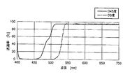
ちなみに、表2と表3のaのダイクロイックミラーコートの分光透過率特性を図15に示し、表2と表3のbのダイクロイックミラーコートの分光透過率特性を図16に示す。これら図15と図16から明らかなように、どちらの例においても、第一波長選択部材によって選択された光の中心波長λを、0度入射において透過しない。 Incidentally, the spectral transmittance characteristics of the dichroic mirror coats a in Tables 2 and 3 are shown in FIG. 15, and the spectral transmittance characteristics of the dichroic mirror coats b in Tables 2 and 3 are shown in FIG. As is apparent from FIGS. 15 and 16, in both examples, the central wavelength λ of the light selected by the first wavelength selection member is not transmitted at 0 degree incidence.
本実施形態に相当するダイクロイックミラーコート124において好ましいと考えられる別の一例では、第一波長選択部材によって選択された光の中心波長λに対して、高屈折率材料の平均的な光学膜厚が約λ/4、低屈折率材料の平均的な光学膜厚が約3×λ/4であるλを効率良く反射する積層と、高屈折率材料の平均的な光学膜厚が約λ/4、低屈折率材料の平均的な光学膜厚が約λ/4である第一波長選択部材によって選択された光よりも短波長側の光を反射する積層を備える。その場合、ダイクロイックミラーコート124は、波長λ付近の反射帯とそれよりも短波長側に広帯域化した反射帯域を有し、反射帯域よりも長波長側に透過帯域を有する。これに該当するダイクロイックミラーコート124として、表2と表3のcにある膜構成を持つダイクロイックミラーコートが例示できる。表2と表3のcのダイクロイックミラーコートの膜構成において、第一波長選択部材によって選択された光の中心波長λを効率良く反射する積層は22〜39層がこれに相当し、λを490nmとしたときにその高屈折率材料の平均的な光学膜厚は約1.17×λ/4、低屈折率材料の平均的な光学膜厚は約3.21×λ/4である。また、第一波長選択部材によって選択された光の中心波長λよりも短波長側の光を反射する積層は4〜17層がこれに相当し、上記同様にλを490nmとしたときにその高屈折率材料の平均的な光学膜厚は約0.96×λ/4、低屈折率材料の平均的な光学膜厚は0.95×λ/4である。
In another example considered to be preferable in the
すなわち、表2と表3のcのダイクロイックミラーにおいては、高屈折率材料の平均的な光学膜厚が約λ/4、低屈折率材料の平均的な光学膜厚が約3×λ/4であるλを効率良く反射する積層と、高屈折率材料の平均的な光学膜厚が約λ/4、低屈折率材料の平均的な光学膜厚が約λ/4である第一波長選択部材によって選択された光よりも短波長側の光を反射する積層を備えている。これらの例における好ましい平均的な光学膜厚の範囲はλの選択によって変わるが、第一波長選択部材によって選択された光の中心波長λを効率良く反射する積層では、高屈折率材料の平均的な光学膜厚がλ/4に対して0.9〜1.2倍の範囲にあり、低屈折率材料の平均的な膜厚がλ/4に対して2.9〜3.4倍の範囲にあるときである。また、第一波長選択部材によって選択された光よりも短波長側の光を反射する積層では、高屈折率材料の平均的な光学膜厚がλ/4に対して0.8〜1.1倍の範囲にあり、低屈折率材料の平均的な膜厚がλ/4に対して0.8〜1.1倍の範囲にあるときである。 That is, in the dichroic mirrors of Table 2 and Table 3c, the average optical film thickness of the high refractive index material is about λ / 4, and the average optical film thickness of the low refractive index material is about 3 × λ / 4. And a first wavelength selection in which the average optical film thickness of the high refractive index material is about λ / 4 and the average optical film thickness of the low refractive index material is about λ / 4. A stack that reflects light shorter than the light selected by the member is provided. The preferred average optical film thickness range in these examples varies depending on the choice of λ, but in a laminate that efficiently reflects the central wavelength λ of the light selected by the first wavelength selection member, the average of the high refractive index material The optical film thickness is in the range of 0.9 to 1.2 times with respect to λ / 4, and the average film thickness of the low refractive index material is 2.9 to 3.4 times with respect to λ / 4. When it is in range. Moreover, in the lamination | stacking which reflects the light of the short wavelength side rather than the light selected by the 1st wavelength selection member, the average optical film thickness of high refractive index material is 0.8-1.1 with respect to (lambda) / 4. This is when the average film thickness of the low refractive index material is in the range of 0.8 to 1.1 times with respect to λ / 4.
ちなみに、表2と表3のcのダイクロイックミラーコートの分光透過率特性を図17に示す。この図17から明らかなように、第一波長選択部材によって選択された光の中心波長λを、0度入射において透過しない。 Incidentally, the spectral transmittance characteristics of the dichroic mirror coats c in Tables 2 and 3 are shown in FIG. As is apparent from FIG. 17, the center wavelength λ of the light selected by the first wavelength selection member is not transmitted at 0 degree incidence.
さらに別の例では、第一波長選択部材によって選択された光の中心波長λに対して、高屈折率材料の平均的な光学膜厚が約3×λ/4、低屈折率材料の平均的な光学膜厚が約3×λ/4であるλを効率良く反射する積層と、高屈折率材料の平均的な光学膜厚が約λ/4、低屈折率材料の平均的な光学膜厚が約λ/4である第一波長選択部材によって選択された光よりも短波長側の光を反射する積層を備える。その場合、ダイクロイックミラーコート124は、波長λ付近の反射帯とそれよりも短波長側に広帯域化した反射帯域を有し、反射帯域よりも長波長側に透過帯域を有する。これに該当するダイクロイックミラーコート124として、表2と表3のdにある膜構成を持つダイクロイックミラーコートが例示できる。表2と表3のdのダイクロイックミラーコートの膜構成において、第一波長選択部材によって選択された光の中心波長λを効率良く反射する積層は29〜48層がこれに相当し、λを515nmとしたときにその高屈折率材料の平均的な光学膜厚は約3.30×λ/4、低屈折率材料の平均的な光学膜厚は約3.28×λ/4である。また、第一波長選択部材によって選択された光の中心波長λよりも短波長側の光を反射する積層は5〜24層がこれに相当し、上記同様にλを515nmとしたときにその高屈折率材料の平均的な光学膜厚は約0.95×λ/4、低屈折率材料の平均的な光学膜厚は0.96×λ/4である。
In yet another example, the average optical film thickness of the high refractive index material is about 3 × λ / 4 with respect to the center wavelength λ of the light selected by the first wavelength selection member, and the average of the low refractive index material is A laminate that efficiently reflects λ with an optical thickness of about 3 × λ / 4, an average optical thickness of a high refractive index material is about λ / 4, and an average optical thickness of a low refractive index material A stack that reflects light having a wavelength shorter than that of light selected by the first wavelength selection member that is approximately λ / 4. In that case, the
すなわち、表2と表3のdのダイクロイックミラーにおいては、高屈折率材料の平均的な光学膜厚が約3×λ/4、低屈折率材料の平均的な光学膜厚が約3×λ/4であるλを効率良く反射する積層と、高屈折率材料の平均的な光学膜厚が約λ/4、低屈折率材料の平均的な光学膜厚が約λ/4である第一波長選択部材によって選択された光よりも短波長側の光を反射する積層を備えている。これらの例における好ましい平均的な光学膜厚の範囲はλの選択によって変わるが、第一波長選択部材によって選択された光の中心波長λを効率良く反射する積層では、高屈折率材料の平均的な光学膜厚がλ/4に対して2.9〜3.4倍の範囲にあり、低屈折率材料の平均的な膜厚がλ/4に対して2.9〜3.4倍の範囲にあるときである。また、第一波長選択部材によって選択された光よりも短波長側の光を反射する積層では、高屈折率材料の平均的な光学膜厚がλ/4に対して0.8〜1.1倍の範囲にあり、低屈折率材料の平均的な膜厚がλ/4に対して0.8〜1.1倍の範囲にあるときである。 That is, in the dichroic mirror of d in Tables 2 and 3, the average optical film thickness of the high refractive index material is about 3 × λ / 4, and the average optical film thickness of the low refractive index material is about 3 × λ. / 4, which efficiently reflects λ, and the average optical film thickness of the high refractive index material is about λ / 4, and the average optical film thickness of the low refractive index material is about λ / 4. A stack that reflects light having a shorter wavelength than the light selected by the wavelength selection member is provided. The preferred average optical film thickness range in these examples varies depending on the choice of λ, but in a laminate that efficiently reflects the central wavelength λ of the light selected by the first wavelength selection member, the average of the high refractive index material The optical film thickness is in the range of 2.9 to 3.4 times λ / 4, and the average film thickness of the low refractive index material is 2.9 to 3.4 times λ / 4. When it is in range. Moreover, in the lamination | stacking which reflects the light of the short wavelength side rather than the light selected by the 1st wavelength selection member, the average optical film thickness of high refractive index material is 0.8-1.1 with respect to (lambda) / 4. This is when the average film thickness of the low refractive index material is in the range of 0.8 to 1.1 times with respect to λ / 4.
ちなみに、表2と表3のdのダイクロイックミラーコートの分光透過率特性を図18に示す。この図18から明らかなように、第一波長選択部材によって選択された光の中心波長λを、0度入射において透過しない。 Incidentally, the spectral transmittance characteristics of the dichroic mirror coats d in Tables 2 and 3 are shown in FIG. As is apparent from FIG. 18, the center wavelength λ of the light selected by the first wavelength selection member is not transmitted at 0 degree incidence.
この例のようなダイクロイックミラーコート124によれば、光分割器が光軸に対して45°に配置された場合に生じるPS偏光の分離を、前述の三例(表2と表3のa,b,c)よりも小さくすることができる。
According to the
光分割器120は、平板状透明基板122のおもて面に施されたダイクロイックミラーコート124が、複数の積層部分を持つことによって反射帯域を確保できる。このため、光分割器120の反射帯域を広域化することが可能である。これによって、第一波長選択部材110に透過帯域が広い透過率特性を持つものを適用することが可能となる(例えば図15に示す場合)。光分割器120は、資料40から発生する蛍光を効率良く透過しながらも、光分割器120を透過する励起光の光量をほとんどなくすことができるため、前述した作用によってノイズの発生を減らすことができる。また、第一波長選択部材110に超広帯域の透過率特性を持つものが適用された場合でも対応が可能である。
The
第二波長選択部材130には、斜めに入射する光によるノイズを低減するために、第一波長選択部材で選択された波長の光を良好に吸収する色ガラスを基板に用いた光学素子が適用される場合が多い。しかし、本実施形態では、光分割器120は、第一波長選択部材110での散乱によって発生した第二波長選択部材130に向かう光をも良好に遮断するため、第二波長選択部材130に、斜めに入射する光を良好に吸収する色ガラスを基板に用いた光学素子を適用する必要がなくなる。
For the second
[第三実施形態]
本発明の第三実施形態による落射顕微鏡の全体の構成は、第一実施形態と実質上同じであり、従って図1に示す通りである。しかし、本実施形態は、光分割器120の第一ダイクロイックミラーコート124と第二ダイクロイックミラーコート126の分光特性が第一実施形態のそれと相違している。本実施形態では、第一ダイクロイックミラーコート124と第二ダイクロイックミラーコート126は、ほぼ同じ帯域を反射し、ほぼ同じ帯域を透過する分光特性を有している。
[Third embodiment]
The overall configuration of the epi-illumination microscope according to the third embodiment of the present invention is substantially the same as that of the first embodiment, and is thus as shown in FIG. However, the present embodiment is different from that of the first embodiment in the spectral characteristics of the first
つまり、第二ダイクロイックミラーコート126は、第一ダイクロイックミラーコート124の反射帯域とほぼ同じ波長帯域の光を反射する。さらに、第一ダイクロイックミラーコート124と第二ダイクロイックミラーコート126は、試料から発せられる蛍光を透過する。
That is, the second
本実施形態の光分割器120では、励起光の透過率は、片面だけにダイクロイックミラーコートが施されている従来の光分割器に比べて二乗で下げられる。その結果、本実施形態の光分割器120は、第一波長選択部材110が狭帯域な場合、励起光をほぼ完全に反射して、透過を抑えることができる。
In the
この結果、蛍光フィルターカセット側面壁での乱反射によるノイズ発生を抑えることができる。 As a result, the generation of noise due to irregular reflection on the side wall of the fluorescent filter cassette can be suppressed.
第一ダイクロイックミラーコート124は、好ましくは、第一実施形態と同様に、屈折率が2.0以上の高屈折率材料と、屈折率が1.5以下の低屈折率材料とを20層以上積層して作られる。その詳細は、第一実施形態において述べた通りである。
The first
さらに、第二ダイクロイックミラーコート126は、好ましくは、屈折率が2.0以上の高屈折率材料と、屈折率が1.5以下の低屈折率材料とを20層以上積層して作られる。一例では、高屈折率材料は平均的な光学膜厚が約λ/4であり、低屈折率材料は平均的な光学膜厚が約λ/4である。その場合、第二ダイクロイックミラーコート126は、波長λの付近に反射帯域を有し、反射帯域よりも長波長に透過帯域を有する。
Further, the second
このような第二ダイクロイックミラーコート126は、第一ダイクロイックミラーコート124の反射帯域を良好に補完することが可能である。
Such a second
本実施形態では、光分割器120は、第一波長選択部材110での散乱によって発生した第二波長選択部材130に向かう光をも良好に遮断するため、第二波長選択部材130に、斜めに入射する光を良好に吸収する色ガラスを基板に用いた光学素子を適用する必要がなくなる。その結果、効率良い蛍光観察を少ないノイズで行なうことが可能になる。さらには、第二波長選択部材130に、エコガラスを基板に用いた光学素子を適用することが可能である。その結果、顕微鏡のガラス部材を、地球環境に優しいエコガラスだけで構成することが可能になる。
In the present embodiment, the
本実施形態においても、第一ダイクロイックミラーコート124と第二ダイクロイックミラーコート126の膜厚は、好ましくは、膜厚の比(第一ダイクロイックミラーコート124の物理膜厚/第二ダイクロイックミラーコート126の物理膜厚)が1/3よりも大きく、3よりも小さいとよい。これによって、第一ダイクロイックミラーコート124を構成する干渉膜による応力と第二ダイクロイックミラーコート126を構成する干渉膜による応力とをほぼ相殺されるため、透明体である平板状透明基板122の反りの発生が抑えられる。これは、照明性能と観察性能の向上につながる。
Also in this embodiment, the film thickness of the first
[第一参考例]
第一参考例による落射顕微鏡の全体の構成は、第一実施形態と実質上同じであり、従って図1に示す通りである。しかし、本参考例は、光分割器120の第一ダイクロイックミラーコート124と第二ダイクロイックミラーコート126の分光特性が第一実施形態のそれと相違している。
[ First Reference Example ]
The overall configuration of the epi-illumination microscope according to the first reference example is substantially the same as that of the first embodiment, and is thus as shown in FIG. However, in this reference example , the spectral characteristics of the first
図19は、第一参考例における、第一波長選択部材110の透過率特性Td2と、平板状透明基板122のおもて面に施された第一ダイクロイックミラーコート124の透過率特性Ta2と、平板状透明基板122のうら面に施された第二ダイクロイックミラーコート126の透過率特性Tb2とを示している。
FIG. 19 shows the transmittance characteristic Td2 of the first
図19に示されるように、第一波長選択部材110の透過率特性Td2の短波長側の透過帯域は、第一ダイクロイックミラーコート124の透過率特性Ta2の反射帯域の中に位置している。また、第二ダイクロイックミラーコート126の透過率特性Tb2の反射帯域は、第一ダイクロイックミラーコート124の透過率特性Ta2の反射帯域よりも長波長側に位置している。第一ダイクロイックミラーコート124の透過率特性Ta2の反射帯域と第二ダイクロイックミラーコート126の透過率特性Tb2の反射帯域は重なることなく離れている。図19のTf3は第二波長選択部材130の透過率特性を示している。
As shown in FIG. 19, the transmission band on the short wavelength side of the transmission characteristic Td2 of the first
図19から分かるように、第一ダイクロイックミラーコート124は、第一波長選択部材110を透過した励起光を反射する。第二ダイクロイックミラーコート126は、第一ダイクロイックミラーコート124の反射帯域に対して長波長側の光を反射する。さらに、第一ダイクロイックミラーコート124と第二ダイクロイックミラーコート126は、試料から発せられる蛍光を透過する。
As can be seen from FIG. 19, the first
本参考例では、光分割器120は、励起光の波長帯域のほかに、それより長波長側にも反射帯域を有している。このため、第一波長選択部材110で発生するある帯域の自家蛍光をカットすることができる。その結果、例えば、第一波長選択部材110での赤の自家蛍光による影響が大きい場合は、赤の波長の光を反射するダイクロイックミラーコートを第二ダイクロイックミラーコート126に適用することによって、また、例えば、TVカメラの近赤外域の感度が強く、近赤外域の自家蛍光をカットしたい場合は、近赤外域を反射するダイクロイックミラーコートを第二ダイクロイックミラーコート126に適用することによって、ノイズを抑えることができる。
In this reference example , the
第一ダイクロイックミラーコート124は、好ましくは、第一実施形態と同様に、屈折率が2.0以上の高屈折率材料と、屈折率が1.5以下の低屈折率材料とを20層以上積層して作られる。その詳細は、第一実施形態において述べた通りである。
The first
本参考例では、光分割器120は、第一波長選択部材110での散乱によって発生した第二波長選択部材130に向かう光をも良好に遮断するため、第二波長選択部材130に、斜めに入射する光を良好に吸収する色ガラスを基板に用いた光学素子を適用する必要がなくなる。その結果、効率良い蛍光観察を少ないノイズで行なうことが可能になる。さらには、第二波長選択部材130に、エコガラスを基板に用いた光学素子を適用することが可能である。その結果、顕微鏡のガラス部材を、地球環境に優しいエコガラスだけで構成することが可能になる。
In the present reference example , the
本参考例においても、第一ダイクロイックミラーコート124と第二ダイクロイックミラーコート126の膜厚は、好ましくは、膜厚の比(第一ダイクロイックミラーコート124の物理膜厚/第二ダイクロイックミラーコート126の物理膜厚)が1/3よりも大きく、3よりも小さいとよい。これによって、第一ダイクロイックミラーコート124を構成する干渉膜による応力と第二ダイクロイックミラーコート126を構成する干渉膜による応力とをほぼ相殺されるため、透明体である平板状透明基板122の反りの発生が抑えられる。これは、照明性能と観察性能の向上につながる。
Also in this reference example , the film thickness of the first
[第二参考例]
第二参考例による落射顕微鏡の全体の構成は、第一実施形態と実質上同じであり、従って図1に示す通りである。しかし、本参考例は、光分割器120の第一ダイクロイックミラーコート124と第二ダイクロイックミラーコート126の分光特性が第一実施形態のそれと相違している。本参考例では、第一波長選択部材110と第二波長選択部材130で選択される光の波長が2つあり、光分割器120もこれに対応するコートが施されている。
[ Second Reference Example ]
The overall configuration of the epi-illumination microscope according to the second reference example is substantially the same as that of the first embodiment, and is thus as shown in FIG. However, in this reference example , the spectral characteristics of the first
図20は、第二参考例における、第一波長選択部材110の透過率特性Td3と、平板状透明基板122のおもて面に施された第一ダイクロイックミラーコート124の透過率特性Ta3と、平板状透明基板122のうら面に施された第二ダイクロイックミラーコート126の透過率特性Tb3と、第二波長選択部材130の透過率特性Tf3とを示している。
FIG. 20 shows the transmittance characteristic Td3 of the first
図20に示されるように、第一波長選択部材110の透過率特性Td3は、二つの透過帯域を有している。第一波長選択部材110の透過率特性Td3の短波長側の透過帯域は、第一ダイクロイックミラーコート124の透過率特性Ta3の反射帯域の中に位置している。第二ダイクロイックミラーコート126の透過率特性Tb3の反射帯域は、第一ダイクロイックミラーコート124の透過率特性Ta3の反射帯域よりも長波長側に位置している。第一ダイクロイックミラーコート124の透過率特性Ta3の反射帯域と第二ダイクロイックミラーコート126の透過率特性Tb3の反射帯域は重なることなく離れている。第一波長選択部材110の透過率特性Td3の長い波長側の透過帯域は、第二ダイクロイックミラーコート126の透過率特性Tb3の反射帯域の中に位置している。
As shown in FIG. 20, the transmittance characteristic Td3 of the first
図20から分かるように、第一ダイクロイックミラーコート124は、第一波長選択部材110を透過した短波長側の励起光を反射する。第二ダイクロイックミラーコート126は、第一波長選択部材110を透過した長波長側の励起光を反射する。また、第一ダイクロイックミラーコート124と第二ダイクロイックミラーコート126は、第一波長選択部材110を透過した二つの波長の励起光の照射によって試料から発せられる二つの波長の蛍光を透過する。さらに、第二波長選択部材130は、二つの波長の励起光の照射によって試料から発せられる二つの波長の蛍光だけを選択的に透過し、結像レンズ50によって、検出装置60の所定位置に結像され試料40に蛍光像を形成する。
As can be seen from FIG. 20, the first
この結果、二つの波長の蛍光を同時に観察することが可能になる。 As a result, two wavelengths of fluorescence can be observed simultaneously.
従来の二波長励起の蛍光フィルターセットでは、光分割器のおもて面に、二つの反射帯域を持つダイクロイックミラーコートが施される。このようなダイクロイックミラーコートは、一つの反射帯域だけを持つダイクロイックミラーコートに比べて、反射率が低い。このため、二波長励起では、一波長励起に比べて、ノイズが発生しやすい。 In a conventional two-wavelength excitation fluorescent filter set, a dichroic mirror coat having two reflection bands is applied to the front surface of an optical splitter. Such a dichroic mirror coat has a lower reflectance than a dichroic mirror coat having only one reflection band. For this reason, noise is more likely to occur in the two-wavelength excitation than in the one-wavelength excitation.
本参考例では、第一ダイクロイックミラーコート124と第二ダイクロイックミラーコート126は、それぞれ、一つの反射帯域だけを有している。このため、本参考例の光分割器120は、反射率の低下を伴うことなく、二波長励起に対応している。その結果、ノイズの発生が低減される。
In this reference example , the first
本参考例では、二波長を選択する例で述べたが、三波長以上の複数の波長の蛍光を同時に観察することも可能である。 In this reference example , the example of selecting two wavelengths has been described, but it is also possible to simultaneously observe fluorescence of a plurality of wavelengths of three or more wavelengths.
第一ダイクロイックミラーコート124は、好ましくは、第一実施形態と同様に、屈折率が2.0以上の高屈折率材料と、屈折率が1.5以下の低屈折率材料とを20層以上積層して作られる。その詳細は、第一実施形態において述べた通りである。
The first
本参考例では、光分割器120は、第一波長選択部材110での散乱によって発生した第二波長選択部材130に向かう光をも良好に遮断するため、第二波長選択部材130に、斜めに入射する光を良好に吸収する色ガラスを基板に用いた光学素子を適用する必要がなくなる。その結果、効率良い蛍光観察を少ないノイズで行なうことが可能になる。さらには、第二波長選択部材130に、エコガラスを基板に用いた光学素子を適用することが可能である。その結果、顕微鏡のガラス部材を、地球環境に優しいエコガラスだけで構成することが可能になる。
In the present reference example , the
本参考例においても、第一ダイクロイックミラーコート124と第二ダイクロイックミラーコート126の膜厚は、好ましくは、膜厚の比(第一ダイクロイックミラーコート124の物理膜厚/第二ダイクロイックミラーコート126の物理膜厚)が1/3よりも大きく、3よりも小さいとよい。これによって、第一ダイクロイックミラーコート124を構成する干渉膜による応力と第二ダイクロイックミラーコート126を構成する干渉膜による応力とをほぼ相殺されるため、透明体である平板状透明基板122の反りの発生が抑えられる。これは、照明性能と観察性能の向上につながる。
Also in this reference example , the film thickness of the first
これまで、図面を参照しながら本発明の実施形態を述べたが、本発明は、これらの実施形態に限定されるものではなく、その要旨を逸脱しない範囲において様々な変形や変更が施されてもよい。 The embodiments of the present invention have been described above with reference to the drawings. However, the present invention is not limited to these embodiments, and various modifications and changes can be made without departing from the scope of the present invention. Also good.
以上で述べた本発明の各実施形態の落射顕微鏡は、正立型の顕微鏡を基本としているが、前記各実施形態に用いられている本発明の技術手段は、そのまま倒立型の顕微鏡にも用いることができる。 The epi-illumination microscope of each embodiment of the present invention described above is based on an upright microscope, but the technical means of the present invention used in each of the above-described embodiments is also used as it is for an inverted microscope. be able to.
また、光源としてはレーザー光源のような単色光源を一つまたは複数もちいてもよい。この場合は、光源側で励起波長が選択されるため、第一波長選択部材が不要になる。 As the light source, one or more monochromatic light sources such as laser light sources may be used. In this case, since the excitation wavelength is selected on the light source side, the first wavelength selection member becomes unnecessary.
本発明は、ひとつには、落射顕微鏡に向けられており、以下の各項に列記する落射顕微鏡を含んでいる。 The present invention is directed, in part, to an epi-illumination microscope and includes epi-illumination microscopes listed in the following sections.
1. 本発明の落射顕微鏡は、試料を照明するための光を発する光源と、光源からの光を選択的に透過する第一波長選択部材と、第一波長選択部材からの光を反射して試料を落射照明するとともに、試料から発せられる光を透過する光分割器と、光分割器を透過した光を選択的に透過する第二波長選択部材とを備えており、光分割器は、透明体と、その透明体に施されたダイクロイックミラーコートとからなり、ダイクロイックミラーコートは第一波長選択部材によって選択された波長の光を効率良く反射する積層と、第一波長選択部材よって選択された光よりも短波長側の光または長波長側の光または同じ帯域の光またはこれらの組み合わせの光を反射する積層とを備えている。 1. The epi-illumination microscope of the present invention includes a light source that emits light for illuminating a sample, a first wavelength selection member that selectively transmits light from the light source, and a sample that reflects light from the first wavelength selection member. An epi-illuminator and an optical splitter that transmits light emitted from the sample, and a second wavelength selection member that selectively transmits the light transmitted through the optical splitter. The dichroic mirror coat is applied to the transparent body, and the dichroic mirror coat is composed of a laminate that efficiently reflects light having a wavelength selected by the first wavelength selection member, and light selected by the first wavelength selection member. And a laminated layer that reflects light on a short wavelength side, light on a long wavelength side, light in the same band, or light of a combination thereof.
2. 本発明の別の落射顕微鏡は、第1項に記載の落射顕微鏡において、光分割器における透明体は第一面と第二面を持ち、透明体に施されたダイクロイックミラーコートは、第一面に施された第一ダイクロイックミラーコートと、第二面に施された第二ダイクロイックミラーコートとを備えている。 2. Another incident light microscope of the present invention is the incident light microscope according to item 1, wherein the transparent body in the optical splitter has a first surface and a second surface, and the dichroic mirror coat applied to the transparent body is the first surface. The first dichroic mirror coat applied to the second surface and the second dichroic mirror coat applied to the second surface.
第1項と第2項の落射顕微鏡によれば、第一波長選択部材によって選択された波長の光と第一波長選択部材から放出された自家蛍光と第一波長選択部材で散乱された光を光分割器によって良好に反射することができる。 According to the epi-illumination microscopes of the first and second terms, the light of the wavelength selected by the first wavelength selection member, the autofluorescence emitted from the first wavelength selection member, and the light scattered by the first wavelength selection member It can be reflected well by the light splitter.
3. 本発明の別の落射顕微鏡は、第2項に記載の落射顕微鏡において、第一ダイクロイックミラーコートは、第一波長選択部材によって選択された波長の光を反射して試料を落射照明するとともに、前記試料から発せられる光を透過する。
3. Another epi-illumination microscope of the present invention is the epi-illumination microscope according to
第3項の落射顕微鏡によれば、第一波長選択部材によって選択された波長の光を第一ダイクロイックミラーコートによって観察光軸から外れることなく試料に照射することができる。 According to the epi-illumination microscope of the third item, it is possible to irradiate the sample with light having a wavelength selected by the first wavelength selection member without deviating from the observation optical axis by the first dichroic mirror coat.
4. 本発明の別の落射顕微鏡は、第3項に記載の落射顕微鏡において、第一ダイクロイックミラーコートは、屈折率が2.0以上の高屈折率材料と、屈折率が1.5以下の低屈折率材料とを20層以上積層して作られており、第一波長選択部材によって選択された光の中心波長λに対して、高屈折率材料の平均的な光学膜厚は約3×λ/4であり、低屈折率材料の平均的な光学膜厚は約λ/4であり、第一ダイクロイックミラーコートは、波長λの付近に前記第一波長選択部材からの光を反射する反射帯域を有し、反射帯域よりも長波長側に前記試料から発せられた光を透過する透過帯域を有している。
4). Another incident light microscope of the present invention is the incident light microscope according to
5. 本発明の別の落射顕微鏡は、第3項に記載の落射顕微鏡において、第一ダイクロイックミラーコートは、屈折率が2.0以上の高屈折率材料と、屈折率が1.5以下の低屈折率材料とを20層以上積層して作られており、第一波長選択部材によって選択された光の中心波長λに対して、高屈折率材料の平均的な光学膜厚は約λ/4であり、低屈折率材料の平均的な光学膜厚は約3×λ/4であり、第一ダイクロイックミラーコートは、波長λの付近に前記第一波長選択部材からの光を反射する反射帯域を有し、反射帯域よりも長波長側に前記試料から発せられた光を透過する透過帯域を有している。
5. Another incident light microscope of the present invention is the incident light microscope according to
6. 本発明の別の落射顕微鏡は、第3項に記載の落射顕微鏡において、第一ダイクロイックミラーコートは、屈折率が2.0以上の高屈折率材料と、屈折率が1.5以下の低屈折率材料とを20層以上積層して作られており、第一波長選択部材によって選択された光の中心波長λに対して、高屈折率材料の平均的な光学膜厚は約3×λ/4であり、低屈折率材料の平均的な光学膜厚は約3×λ/4であり、第一ダイクロイックミラーコートは、波長λの付近に前記第一波長選択部材からの光を反射する反射帯域を有し、反射帯域よりも長波長側に前記試料から発せられた光を透過する透過帯域を有している。
6). Another incident light microscope of the present invention is the incident light microscope according to
第4項と第5項と第6項の落射顕微鏡によれば、光分割器が光軸に対して45度に配置された場合に生じるPS偏光の分離を小さくできる。このため、光分割器は、第一波長選択部材によって選択される波長帯域の光を効率良く反射し、第二波長選択部材によって選択される波長帯域の光を効率良く透過することができる。特に第6項の落射顕微鏡は、光分割器が光軸に対して45度に配置された場合に生じるPS偏光の分離を、第4項と第5項の落射顕微鏡よりも小さくすることができる。 According to the epi-illumination microscopes of the fourth, fifth and sixth terms, it is possible to reduce the separation of PS polarized light that occurs when the optical splitter is arranged at 45 degrees with respect to the optical axis. For this reason, the optical splitter can efficiently reflect the light in the wavelength band selected by the first wavelength selection member and efficiently transmit the light in the wavelength band selected by the second wavelength selection member. In particular, the epi-illumination microscope of the sixth term can make the separation of PS polarized light generated when the optical splitter is arranged at 45 degrees with respect to the optical axis, smaller than the epi-illumination microscope of the fourth and fifth terms. .
7. 本発明の別の落射顕微鏡は、第3項に記載の落射顕微鏡において、第二ダイクロイックミラーコートは、第一ダイクロイックミラーコートの反射帯域に対して、短波長側の光または長波長側の光または同じ帯域の光またはこれらの組み合わせの光を反射するとともに、試料から発せられる光を透過する。
7). Another incident light microscope of the present invention is the incident light microscope according to
第7項の落射顕微鏡によれば、光分割器の反射帯域を広げたり、複数の波長の光で落射照明したり、特定の波長帯域に対する光分割器の反射率を上げたりすることができる。 According to the epi-illumination microscope of the seventh item, it is possible to widen the reflection band of the optical divider, to carry out epi-illumination with light of a plurality of wavelengths, or to increase the reflectance of the optical divider for a specific wavelength band.
8. 本発明の別の落射顕微鏡は、第7項に記載の落射顕微鏡において、第二ダイクロイックミラーコートは、屈折率が2.0以上の高屈折率材料と、屈折率が1.5以下の低屈折率材料とを20層以上積層して作られており、短波長側の光λまたは長波長側の光λまたは同じ帯域の光λまたはこれらの組み合わせの光の中心波長λに対して、高屈折率材料は平均的な光学膜厚が約λ/4であり、低屈折率材料は平均的な光学膜厚が約λ/4であり、第二ダイクロイックミラーコートは、波長λの付近に反射帯域を有し、反射帯域よりも長波長に透過帯域を有している。 8). Another incident light microscope according to the present invention is the incident light microscope according to item 7, wherein the second dichroic mirror coat includes a high refractive index material having a refractive index of 2.0 or more and a low refractive index having a refractive index of 1.5 or less. 20 or more layers of the refractive index material, and is highly refracted with respect to the center wavelength λ of the light λ on the short wavelength side, the light λ on the long wavelength side, the light λ in the same band, or a combination thereof. The refractive index material has an average optical film thickness of about λ / 4, the low refractive index material has an average optical film thickness of about λ / 4, and the second dichroic mirror coat has a reflection band near the wavelength λ. And has a transmission band at a wavelength longer than the reflection band.
第8項の落射顕微鏡によれば、より広い波長帯域の光で落射照明することができる。
According to the epi-illumination microscope of
9. 本発明の別の落射顕微鏡は、第8項に記載の落射顕微鏡において、第一ダイクロイックミラーコートは、屈折率が2.0以上の高屈折率材料と、屈折率が1.5以下の低屈折率材料とを20層以上積層して作られており、第一波長選択部材によって選択された光の中心波長λに対して、高屈折率材料の平均的な光学膜厚は約3×λ/4であり、低屈折率材料の平均的な光学膜厚は約λ/4であり、第一ダイクロイックミラーコートは、波長λの付近に反射帯域を有し、反射帯域よりも長波長側に透過帯域を有している。
9. Another incident light microscope according to the present invention is the incident light microscope according to
10. 本発明の別の落射顕微鏡は、第8項に記載の落射顕微鏡において、第一ダイクロイックミラーコートは、屈折率が2.0以上の高屈折率材料と、屈折率が1.5以下の低屈折率材料とを20層以上積層して作られており、第一波長選択部材によって選択された光の中心波長λに対して、高屈折率材料の平均的な光学膜厚は約λ/4であり、低屈折率材料の平均的な光学膜厚は約3×λ/4であり、第一ダイクロイックミラーコートは、波長λの付近に反射帯域を有し、反射帯域よりも長波長側に透過帯域を有している。
10. Another incident light microscope according to the present invention is the incident light microscope according to
11. 本発明の別の落射顕微鏡は、第8項に記載の落射顕微鏡において、第一ダイクロイックミラーコートは、屈折率が2.0以上の高屈折率材料と、屈折率が1.5以下の低屈折率材料とを20層以上積層して作られており、第一波長選択部材によって選択された光の中心波長λに対して、高屈折率材料の平均的な光学膜厚は約3×λ/4であり、低屈折率材料の平均的な光学膜厚は約3×λ/4であり、第一ダイクロイックミラーコートは、波長λの付近に反射帯域を有し、反射帯域よりも長波長側に生じる透過帯域を有している。
11. Another incident light microscope according to the present invention is the incident light microscope according to
第9項と第10項と第11項の落射顕微鏡によれば、第一ダイクロイックミラーコートによって、光分割器が光軸に対して45度に配置された場合に生じるPS偏光の分離を小くできる。さらに、第二ダイクロイックミラーコートによって第一ダイクロイックミラーコートの反射帯域を補完することができる。これによって、第一波長選択部材から放出された自家蛍光や第一波長選択部材で散乱された光を効率良く反射することができる。 According to the epi-illumination microscopes of the ninth, tenth and eleventh terms, the first dichroic mirror coat reduces the separation of PS polarized light which occurs when the optical splitter is arranged at 45 degrees with respect to the optical axis. it can. Furthermore, the reflection band of the first dichroic mirror coat can be supplemented by the second dichroic mirror coat. Thereby, the autofluorescence emitted from the first wavelength selection member and the light scattered by the first wavelength selection member can be efficiently reflected.
12. 本発明の別の落射顕微鏡は、第1項または第2項に記載の落射顕微鏡において、第一波長選択部材は、光源からの光線のうちの複数の波長の光を選択的に透過し、光分割器は、第一波長選択部材を透過した光を反射するとともに、試料から発せられる複数の波長の光を透過し、第二波長選択部材は、光分割器を透過した光のうちの所定の複数の波長の光を選択的に透過する。
12 Another epi-illumination microscope of the present invention is the epi-illumination microscope according to
第12項の落射顕微鏡によれば、第一波長選択部材によって選択された複数の波長の光で試料を落射照明することができる。 According to the epi-illumination microscope of the twelfth aspect, the sample can be epi-illuminated with light of a plurality of wavelengths selected by the first wavelength selection member.
13. 本発明の別の落射顕微鏡は、第12項に記載の落射顕微鏡において、第一ダイクロイックミラーコートは、第一波長選択部材によって選択された複数の波長の光のうち、少なくとも一つの波長の光を反射して試料を落射照明する。 13. Another epi-illumination microscope of the present invention is the epi-illumination microscope according to item 12, wherein the first dichroic mirror coat emits light having at least one wavelength among light having a plurality of wavelengths selected by the first wavelength selection member. Reflect and illuminate the sample.
第13項の落射顕微鏡によれば、第一波長選択部材によって選択された複数の波長の光のうちの少なくとも一つの波長の光で試料を落射照明することができる。 According to the epi-illumination microscope of the thirteenth aspect, the sample can be epi-illuminated with light of at least one of the light of a plurality of wavelengths selected by the first wavelength selection member.
14. 本発明の別の落射顕微鏡は、第13項に記載の落射顕微鏡において、第二ダイクロイックミラーコートは、第一波長選択部材によって選択された複数の波長の光のうち、第一ダイクロイックミラーコートによって反射されない波長の光を反射して試料を落射照明する。 14 Another incident light microscope of the present invention is the incident light microscope according to item 13, wherein the second dichroic mirror coat is reflected by the first dichroic mirror coat among the light having a plurality of wavelengths selected by the first wavelength selecting member. Reflect the light of the wavelength that is not reflected and illuminate the sample.
第14項の落射顕微鏡によれば、第一波長選択部材によって選択された複数の波長の光で試料を落射照明することができる。 According to the epi-illumination microscope of the fourteenth aspect, the sample can be epi-illuminated with light of a plurality of wavelengths selected by the first wavelength selection member.
15. 本発明の別の落射顕微鏡は、第1項〜第14項に記載の落射顕微鏡において、第一ダイクロイックミラーコートと第二ダイクロイックミラーコートの膜厚の比(第一ダイクロイックミラーコートの物理膜厚/第二ダイクロイックミラーコートの物理膜厚)が1/3よりも大きく、3よりも小さい。 15. Another epi-illumination microscope of the present invention is the epi-illumination microscope according to any one of items 1 to 14, wherein the ratio of the film thickness of the first dichroic mirror coat to the second dichroic mirror coat (physical film thickness of the first dichroic mirror coat / The physical film thickness of the second dichroic mirror coat) is larger than 1/3 and smaller than 3.
第15項の落射顕微鏡によれば、第一ダイクロイックミラーコートを構成する干渉膜による応力と第二ダイクロイックミラーコートを構成する干渉膜による応力とをほぼ相殺させることができる。これによって、光分割器の透明体の変形が抑えられる。 According to the epi-illumination microscope of the fifteenth term, the stress caused by the interference film constituting the first dichroic mirror coat and the stress caused by the interference film constituting the second dichroic mirror coat can be substantially offset. Thereby, deformation of the transparent body of the light splitter is suppressed.
本発明は、ひとつには、蛍光フィルターセットに向けられており、以下の各項に列記する蛍光フィルターセットを含んでいる。 One aspect of the present invention is directed to a fluorescent filter set, and includes the fluorescent filter set listed in the following sections.
16. 本発明の蛍光フィルターセットは、励起光を選択的に透過する第一波長選択部材と、第一波長選択部材からの励起光を反射して試料を落射照明するとともに、試料から発せられる蛍光を透過する光分割器と、光分割器を透過した蛍光を選択的に透過する第二波長選択部材とを備えており、光分割器は、透明体と、その透明体に施されたダイクロイックミラーコートとからなり、ダイクロイックミラーコートは第一波長選択部材によって選択された波長の光を効率良く反射する積層と、第一波長選択部材よって選択された光よりも短波長側の光または長波長側の光または同じ帯域の光またはこれらの組み合わせの光を反射する積層とを備えている。 16. The fluorescent filter set of the present invention includes a first wavelength selection member that selectively transmits excitation light, and reflects the excitation light from the first wavelength selection member to illuminate the sample and transmits fluorescence emitted from the sample. And a second wavelength selection member that selectively transmits the fluorescence transmitted through the light splitter. The light splitter includes a transparent body and a dichroic mirror coat applied to the transparent body. The dichroic mirror coat comprises a laminate that efficiently reflects light having a wavelength selected by the first wavelength selection member, and light having a shorter wavelength or longer wavelength than the light selected by the first wavelength selection member. Alternatively, a stack that reflects light in the same band or a combination thereof is provided.
17. 本発明の別の落射顕微鏡は、第1項に記載の落射顕微鏡において、光分割器における透明体は第一面と第二面を持ち、透明体に施されたダイクロイックミラーコートは、第一面に施された第一ダイクロイックミラーコートと、第二面に施された第二ダイクロイックミラーコートとを備えている。 17. Another incident light microscope of the present invention is the incident light microscope according to item 1, wherein the transparent body in the optical splitter has a first surface and a second surface, and the dichroic mirror coat applied to the transparent body is the first surface. The first dichroic mirror coat applied to the second surface and the second dichroic mirror coat applied to the second surface.
第16項と第17項の蛍光フィルターセットによれば、第一波長選択部材によって選択された波長の光と第一波長選択部材から放出された自家蛍光と第一波長選択部材で散乱された光を光分割器によって良好に反射することができる。 According to the fluorescent filter set of the sixteenth and seventeenth items, light having a wavelength selected by the first wavelength selection member, autofluorescence emitted from the first wavelength selection member, and light scattered by the first wavelength selection member Can be satisfactorily reflected by the light splitter.
18. 本発明の別の蛍光フィルターセットは、第17項に記載の蛍光フィルターセットにおいて、第一ダイクロイックミラーコートは、第一波長選択部材によって選択された波長の光を反射して試料を落射照明する。 18. Another fluorescent filter set according to the present invention is the fluorescent filter set according to item 17, wherein the first dichroic mirror coat reflects the light of the wavelength selected by the first wavelength selection member to illuminate the sample by epi-illumination.
第18項の蛍光フィルターセットによれば、第一波長選択部材によって選択された波長の光を第一ダイクロイックミラーコートによって観察光軸から外れることなく試料に照射することができる。 According to the fluorescent filter set of Item 18, the sample can be irradiated with the light having the wavelength selected by the first wavelength selection member without deviating from the observation optical axis by the first dichroic mirror coat.
19. 本発明の別の蛍光フィルターセットは、第18項に記載の蛍光フィルターセットにおいて、第一ダイクロイックミラーコートは、屈折率が2.0以上の高屈折率材料と、屈折率が1.5以下の低屈折率材料とを20層以上積層して作られており、第一波長選択部材によって選択された光の中心波長λに対して、高屈折率材料の平均的な光学膜厚は約3×λ/4であり、低屈折率材料の平均的な光学膜厚は約λ/4であり、第一ダイクロイックミラーコートは、波長λの付近に前記第一波長選択部材からの光を反射する反射帯域を有し、反射帯域よりも長波長側に前記試料から発せられた光を透過する透過帯域を有している。 19. Another fluorescent filter set of the present invention is the fluorescent filter set according to item 18, wherein the first dichroic mirror coat includes a high refractive index material having a refractive index of 2.0 or more and a refractive index of 1.5 or less. 20 or more layers of low refractive index materials are laminated, and the average optical film thickness of the high refractive index material is about 3 × with respect to the center wavelength λ of the light selected by the first wavelength selection member. λ / 4, the average optical film thickness of the low refractive index material is about λ / 4, and the first dichroic mirror coat reflects light from the first wavelength selection member in the vicinity of the wavelength λ. It has a transmission band that transmits light emitted from the sample on the longer wavelength side than the reflection band.
20. 本発明の別の蛍光フィルターセットは、第18項に記載の蛍光フィルターセットにおいて、第一ダイクロイックミラーコートは、屈折率が2.0以上の高屈折率材料と、屈折率が1.5以下の低屈折率材料とを20層以上積層して作られており、第一波長選択部材によって選択された光の中心波長λに対して、高屈折率材料の平均的な光学膜厚は約λ/4であり、低屈折率材料の平均的な光学膜厚は約3×λ/4であり、第一ダイクロイックミラーコートは、波長λの付近に前記第一波長選択部材からの光を反射する反射帯域を有し、反射帯域よりも長波長側に前記試料から発せられた光を透過する透過帯域を有している。 20. Another fluorescent filter set of the present invention is the fluorescent filter set according to item 18, wherein the first dichroic mirror coat includes a high refractive index material having a refractive index of 2.0 or more and a refractive index of 1.5 or less. 20 or more layers of the low refractive index material are laminated, and the average optical film thickness of the high refractive index material is about λ / with respect to the center wavelength λ of the light selected by the first wavelength selection member. 4, the average optical film thickness of the low refractive index material is about 3 × λ / 4, and the first dichroic mirror coat reflects light from the first wavelength selection member in the vicinity of the wavelength λ. It has a transmission band that transmits light emitted from the sample on the longer wavelength side than the reflection band.
21. 本発明の別の蛍光フィルターセットは、第18項に記載の蛍光フィルターセットにおいて、第一ダイクロイックミラーコートは、屈折率が2.0以上の高屈折率材料と、屈折率が1.5以下の低屈折率材料とを20層以上積層して作られており、第一波長選択部材によって選択された光の中心波長λに対して、高屈折率材料の平均的な光学膜厚は約3×λ/4であり、低屈折率材料の平均的な光学膜厚は約3×λ/4であり、第一ダイクロイックミラーコートは、波長λの付近に前記第一波長選択部材からの光を反射する反射帯域を有し、反射帯域よりも長波長側に前記試料から発せられた光を透過する透過帯域を有している。 21. Another fluorescent filter set of the present invention is the fluorescent filter set according to item 18, wherein the first dichroic mirror coat includes a high refractive index material having a refractive index of 2.0 or more and a refractive index of 1.5 or less. 20 or more layers of low refractive index materials are laminated, and the average optical film thickness of the high refractive index material is about 3 × with respect to the center wavelength λ of the light selected by the first wavelength selection member. λ / 4, the average optical film thickness of the low refractive index material is about 3 × λ / 4, and the first dichroic mirror coat reflects light from the first wavelength selection member in the vicinity of the wavelength λ. And has a transmission band that transmits light emitted from the sample on a longer wavelength side than the reflection band.
第19項と第20項と第21項の蛍光フィルターセットによれば、光分割器が光軸に対して45度に配置された場合に生じるPS偏光の分離を小さくできる。このため、光分割器は、第一波長選択部材によって選択される波長帯域の光を効率良く反射し、第二波長選択部材によって選択される波長帯域の光を効率良く透過することができる。特に第21項の蛍光フィルターセットは、光分割器が光軸に対して45度に配置された場合に生じるPS偏光の分離を、第19項と第20項の蛍光フィルターセットよりも小さくすることができる。
According to the fluorescent filter set of the 19th term, the 20th term and the 21st term, it is possible to reduce the separation of PS polarized light which occurs when the light splitter is arranged at 45 degrees with respect to the optical axis. For this reason, the optical splitter can efficiently reflect the light in the wavelength band selected by the first wavelength selection member and efficiently transmit the light in the wavelength band selected by the second wavelength selection member. In particular, in the fluorescent filter set of item 21, the PS polarized light separation that occurs when the light splitter is arranged at 45 degrees with respect to the optical axis should be smaller than the fluorescent filter set of
22. 本発明の別の蛍光フィルターセットは、第18項に記載の蛍光フィルターセットにおいて、第二ダイクロイックミラーコートは、第一ダイクロイックミラーコートの反射帯域に対して、短波長側の光または長波長側の光または同じ帯域の光またはこれらの組み合わせの光を反射するとともに、試料から発せられる光を透過する。 22. Another fluorescent filter set according to the present invention is the fluorescent filter set according to item 18, wherein the second dichroic mirror coat has a short wavelength side light or a long wavelength side relative to the reflection band of the first dichroic mirror coat. Reflects light, light in the same band, or a combination thereof, and transmits light emitted from the sample.
第22項の蛍光フィルターセットによれば、光分割器の反射帯域を広げたり、複数の波長の光で落射照明したり、特定の波長帯域に対する光分割器の反射率を上げたりすることができる。 According to the fluorescent filter set of the twenty-second item, it is possible to widen the reflection band of the optical divider, to perform epi-illumination with light of a plurality of wavelengths, or to increase the reflectance of the optical divider for a specific wavelength band. .
23. 本発明の別の蛍光フィルターセットは、第22項に記載の蛍光フィルターセットにおいて、第二ダイクロイックミラーコートは、屈折率が2.0以上の高屈折率材料と、屈折率が1.5以下の低屈折率材料とを20層以上積層して作られており、短波長側の光λまたは長波長側の光λまたは同じ帯域の光λまたはこれらの組み合わせの光の中心波長λに対して、高屈折率材料は平均的な光学膜厚が約λ/4であり、低屈折率材料は平均的な光学膜厚が約λ/4であり、第二ダイクロイックミラーコートは、波長λの付近に反射帯域を有し、反射帯域よりも長波長に透過帯域を有している。 23. Another fluorescent filter set according to the present invention is the fluorescent filter set according to item 22, wherein the second dichroic mirror coat includes a high refractive index material having a refractive index of 2.0 or more and a refractive index of 1.5 or less. It is made by laminating 20 or more layers with a low refractive index material, and with respect to the center wavelength λ of the light λ on the short wavelength side, the light λ on the long wavelength side, the light λ in the same band, or the combination of these, The high refractive index material has an average optical film thickness of about λ / 4, the low refractive index material has an average optical film thickness of about λ / 4, and the second dichroic mirror coat is in the vicinity of the wavelength λ. It has a reflection band and a transmission band at a longer wavelength than the reflection band.
第23項の蛍光フィルターセットによれば、より広い波長帯域の光で落射照明することができる。
According to the fluorescent filter set of
24. 本発明の別の蛍光フィルターセットは、第23項に記載の蛍光フィルターセットにおいて、第一ダイクロイックミラーコートは、屈折率が2.0以上の高屈折率材料と、屈折率が1.5以下の低屈折率材料とを20層以上積層して作られており、第一波長選択部材によって選択された光の中心波長λに対して、高屈折率材料の平均的な光学膜厚は約3×λ/4であり、低屈折率材料の平均的な光学膜厚は約λ/4であり、第一ダイクロイックミラーコートは、波長λの付近に反射帯域を有し、反射帯域よりも長波長側に透過帯域を有している。
24. Another fluorescent filter set of the present invention is the fluorescent filter set according to
25. 本発明の別の蛍光フィルターセットは、第23項に記載の蛍光フィルターセットにおいて、第一ダイクロイックミラーコートは、屈折率が2.0以上の高屈折率材料と、屈折率が1.5以下の低屈折率材料とを20層以上積層して作られており、第一波長選択部材によって選択された光の中心波長λに対して、高屈折率材料の平均的な光学膜厚は約λ/4であり、低屈折率材料の平均的な光学膜厚は約3×λ/4であり、第一ダイクロイックミラーコートは、波長λの付近に反射帯域を有し、反射帯域よりも長波長側に透過帯域を有している。
25. Another fluorescent filter set of the present invention is the fluorescent filter set according to
26. 本発明の別の蛍光フィルターセットは、第23項に記載の蛍光フィルターセットにおいて、第一ダイクロイックミラーコートは、屈折率が2.0以上の高屈折率材料と、屈折率が1.5以下の低屈折率材料とを20層以上積層して作られており、第一波長選択部材によって選択された光の中心波長λに対して、高屈折率材料の平均的な光学膜厚は約3×λ/4であり、低屈折率材料の平均的な光学膜厚は約3×λ/4であり、第一ダイクロイックミラーコートは、波長λの付近に反射帯域を有し、反射帯域よりも長波長側に生じる透過帯域を有している。
26. Another fluorescent filter set of the present invention is the fluorescent filter set according to
第24項と第25項と第26項の蛍光フィルターセットによれば、第一ダイクロイックミラーコートによって、光分割器が光軸に対して45度に配置された場合に生じるPS偏光の分離を小くできる。さらに、第二ダイクロイックミラーコートによって第一ダイクロイックミラーコートの反射帯域を補完することができる。これによって、第一波長選択部材から放出された自家蛍光や第一波長選択部材で散乱された光を効率良く反射することができる。 According to the fluorescent filter set of Item 24, Item 25, and Item 26, the first dichroic mirror coat reduces the separation of PS polarized light that occurs when the optical splitter is arranged at 45 degrees with respect to the optical axis. I can. Furthermore, the reflection band of the first dichroic mirror coat can be supplemented by the second dichroic mirror coat. Thereby, the autofluorescence emitted from the first wavelength selection member and the light scattered by the first wavelength selection member can be efficiently reflected.
27. 本発明の別の蛍光フィルターセットは、第16項または第17項に記載の蛍光フィルターセットにおいて、第一波長選択部材は、光源からの光線のうちの複数の波長の光を選択的に透過し、光分割器は、第一波長選択部材を透過した光を反射するとともに、試料から発せられる複数の波長の光を透過し、第二波長選択部材は、光分割器を透過した光のうちの所定の複数の波長の光を選択的に透過する。 27. Another fluorescent filter set according to the present invention is the fluorescent filter set according to item 16 or 17, wherein the first wavelength selection member selectively transmits light having a plurality of wavelengths among light beams from the light source. The light splitter reflects light transmitted through the first wavelength selection member and transmits light of a plurality of wavelengths emitted from the sample, and the second wavelength selection member includes light out of the light transmitted through the light splitter. It selectively transmits light of a plurality of predetermined wavelengths.
第27項の蛍光フィルターセットによれば、第一波長選択部材によって選択された複数の波長の光で試料を落射照明することができる。 According to the fluorescent filter set of the twenty-seventh item, the sample can be incidentally illuminated with light of a plurality of wavelengths selected by the first wavelength selection member.
28. 本発明の別の蛍光フィルターセットは、第27項に記載の蛍光フィルターセットにおいて、第一ダイクロイックミラーコートは、第一波長選択部材によって選択された複数の波長の光のうち、少なくとも一つの波長の光を反射して試料を落射照明する。 28. Another fluorescent filter set according to the present invention is the fluorescent filter set according to item 27, wherein the first dichroic mirror coat has at least one wavelength of light of a plurality of wavelengths selected by the first wavelength selection member. Reflect the light and illuminate the sample.
第28項の蛍光フィルターセットによれば、第一波長選択部材によって選択された複数の波長の光のうちの少なくとも一つの波長の光で試料を落射照明することができる。 According to the fluorescence filter set of the twenty-eighth aspect, the sample can be incidentally illuminated with light of at least one wavelength among the light of a plurality of wavelengths selected by the first wavelength selection member.
29. 本発明の別の蛍光フィルターセットは、第28項に記載の蛍光フィルターセットにおいて、第二ダイクロイックミラーコートは、第一波長選択部材によって選択された複数の波長の光のうち、第一ダイクロイックミラーコートによって反射されない波長の光を反射して試料を落射照明する。 29. Another fluorescent filter set according to the present invention is the fluorescent filter set according to item 28, wherein the second dichroic mirror coat is a first dichroic mirror coat among the lights having a plurality of wavelengths selected by the first wavelength selection member. The sample is reflected by reflecting light having a wavelength that is not reflected by.
第29項の蛍光フィルターセットによれば、第一波長選択部材によって選択された複数の波長の光で試料を落射照明することができる。 According to the fluorescence filter set of item 29, the sample can be incidentally illuminated with light of a plurality of wavelengths selected by the first wavelength selection member.
30. 本発明の別の蛍光フィルターセットは、第16項〜第29項に記載の蛍光フィルターセットにおいて、第一ダイクロイックミラーコートと第二ダイクロイックミラーコートの膜厚の比(第一ダイクロイックミラーコートの物理膜厚/第二ダイクロイックミラーコートの物理膜厚)が1/3よりも大きく、3よりも小さい。 30. Another fluorescent filter set of the present invention is the fluorescent filter set according to any one of Items 16 to 29, wherein the ratio of the film thickness of the first dichroic mirror coat to the second dichroic mirror coat (physical film of the first dichroic mirror coat) (Thickness / physical film thickness of the second dichroic mirror coat) is larger than 1/3 and smaller than 3.
第30項の蛍光フィルターセットによれば、第一ダイクロイックミラーコートを構成する干渉膜による応力と第二ダイクロイックミラーコートを構成する干渉膜による応力とをほぼ相殺させることができる。これによって、光分割器の透明体の変形が抑えられる。
According to the fluorescent filter set of
10…光源、20…照明光学系、30…対物レンズ、40…試料、50…結像レンズ、60…検出装置、100…蛍光フィルターセット、110…第一波長選択部材、112…第一光学フィルター、120…光分割器、122…平板状透明基板、124…第一ダイクロイックミラーコート、126…第二ダイクロイックミラーコート、128…ダイクロイックミラーコート、130…第二波長選択部材、132…第二光学フィルター。
DESCRIPTION OF
Claims (30)
前記光源からの光を選択的に透過する第一波長選択部材と、
前記第一波長選択部材からの光を反射して試料を落射照明するとともに、試料から発せられる光を透過する光分割器と、
前記光分割器を透過した光を選択的に透過する第二波長選択部材とを備えており、
前記光分割器は、透明体と、その透明体に施されたダイクロイックミラーコートとからなり、前記ダイクロイックミラーコートは前記第一波長選択部材によって選択された波長の光を効率良く反射する第一ダイクロイックミラーコートと、前記第一波長選択部材よって選択された光よりも短波長側の光または同じ帯域の光またはこれらの組み合わせの光を反射する前記第一ダイクロイックミラーコートと反射帯域が部分的に重なっている第二ダイクロイックミラーコートとを備えていることを特徴とする落射顕微鏡。 A light source that emits light to illuminate the sample;
A first wavelength selection member that selectively transmits light from the light source;
As well as incident illumination of the sample by reflecting light from the first wavelength selection member, a beam splitter which transmits light emitted from the sample,
A second wavelength selection member that selectively transmits light transmitted through the light splitter,
The optical splitter has a transparent body, made its transparent body is subjected dichroic mirror coating, the dichroic mirror coat first dichroic reflecting efficiently the light of a wavelength selected by the first wavelength selection member a mirror coating, wherein the first dichroic mirror coated with reflective band than the first wavelength selecting member by being selected by the light reflecting light of the light, or a combination of these light or the same band on the short wavelength side partially overlap An epi-illumination microscope comprising a second dichroic mirror coat .
前記第一波長選択部材からの励起光を反射して試料を落射照明するとともに、試料から発せられる蛍光を透過する光分割器と、
前記光分割器を透過した蛍光を選択的に透過する第二波長選択部材とを備えており、
前記光分割器は、透明体と、その透明体に施されたダイクロイックミラーコートとからなり、前記ダイクロイックミラーコートは前記第一波長選択部材によって選択された波長の光を効率良く反射する第一ダイクロイックミラーコートと、第一波長選択部材よって選択された光よりも短波長側の光または同じ帯域の光またはこれらの組み合わせの光を反射する前記第一ダイクロイックミラーコートと反射帯域が部分的に重なっている第二ダイクロイックミラーコートとを備えていることを特徴とする蛍光フィルターセット。 A first wavelength selection member that selectively transmits excitation light;
A light splitter that reflects the excitation light from the first wavelength selection member and illuminates the sample incidentally, and transmits fluorescence emitted from the sample;
A second wavelength selection member that selectively transmits fluorescence transmitted through the light splitter,
The optical splitter has a transparent body, made its transparent body is subjected dichroic mirror coating, the dichroic mirror coat first dichroic reflecting efficiently the light of a wavelength selected by the first wavelength selection member a mirror coating, the first dichroic mirror coated with a reflection band than light selected by the first wavelength selection member to reflect light or light of a combination of these light or the same band on the short wavelength side partially overlap second dichroic fluorescence filter set, characterized in that it comprises a dichroic mirror coat are.
Priority Applications (2)
| Application Number | Priority Date | Filing Date | Title |
|---|---|---|---|
| JP2004355747A JP4837279B2 (en) | 2004-04-05 | 2004-12-08 | Epi-illumination microscope and fluorescent filter set |
| US11/097,351 US7285787B2 (en) | 2004-04-05 | 2005-04-04 | Epi-illumination microscope and fluorescence filter set |
Applications Claiming Priority (3)
| Application Number | Priority Date | Filing Date | Title |
|---|---|---|---|
| JP2004111356 | 2004-04-05 | ||
| JP2004111356 | 2004-04-05 | ||
| JP2004355747A JP4837279B2 (en) | 2004-04-05 | 2004-12-08 | Epi-illumination microscope and fluorescent filter set |
Publications (2)
| Publication Number | Publication Date |
|---|---|
| JP2005321753A JP2005321753A (en) | 2005-11-17 |
| JP4837279B2 true JP4837279B2 (en) | 2011-12-14 |
Family
ID=35095928
Family Applications (1)
| Application Number | Title | Priority Date | Filing Date |
|---|---|---|---|
| JP2004355747A Expired - Lifetime JP4837279B2 (en) | 2004-04-05 | 2004-12-08 | Epi-illumination microscope and fluorescent filter set |
Country Status (2)
| Country | Link |
|---|---|
| US (1) | US7285787B2 (en) |
| JP (1) | JP4837279B2 (en) |
Families Citing this family (15)
| Publication number | Priority date | Publication date | Assignee | Title |
|---|---|---|---|---|
| US20090080194A1 (en) * | 2006-02-15 | 2009-03-26 | Li-Cor, Inc. | Fluorescence filtering system and method for molecular imaging |
| JP5021254B2 (en) * | 2006-09-06 | 2012-09-05 | オリンパス株式会社 | Control method of microscope apparatus, microscope apparatus |
| GB0715168D0 (en) * | 2007-08-03 | 2007-09-12 | Enigma Diagnostics Ltd | Illumination apparatus for use in fluorescence-based detection |
| JP2009122203A (en) * | 2007-11-12 | 2009-06-04 | Shimadzu Corp | Optical filter, filter set for fluorescence analysis and fluorescence measuring device using this optical filter |
| DE102008035770A1 (en) * | 2008-07-31 | 2010-02-18 | Eads Deutschland Gmbh | Optical particle detector and detection method |
| WO2010032306A1 (en) * | 2008-09-18 | 2010-03-25 | 株式会社島津製作所 | Fluorescent image detector and method for detecting fluorescent image |
| US9375172B2 (en) | 2011-11-07 | 2016-06-28 | Corning Incorporated | Apparatus for substance detection |
| WO2013070485A1 (en) * | 2011-11-07 | 2013-05-16 | Corning Incorporated | Apparatus for substance detection |
| JP6237626B2 (en) * | 2012-07-19 | 2017-11-29 | 株式会社ニコン | Optical apparatus and imaging apparatus |
| WO2015087824A1 (en) * | 2013-12-09 | 2015-06-18 | 株式会社ニコン | Optical apparatus, measuring apparatus, measuring method, screening apparatus, and screening method |
| JP6457186B2 (en) * | 2014-03-27 | 2019-01-23 | オリンパス株式会社 | Fluorescent cube and optical microscope |
| US9541750B2 (en) | 2014-06-23 | 2017-01-10 | Li-Cor, Inc. | Telecentric, wide-field fluorescence scanning systems and methods |
| JP2018529125A (en) * | 2015-09-02 | 2018-10-04 | インスコピックス, インコーポレイテッド | System and method for color imaging |
| JP2018533768A (en) | 2015-11-05 | 2018-11-15 | インスコピックス, インコーポレイテッド | System and method for optogenetics imaging |
| US9645291B1 (en) | 2016-04-18 | 2017-05-09 | Ii-Vi Incorporated | Voltage-tunable optical filters for instrumentation applications |
Family Cites Families (28)
| Publication number | Priority date | Publication date | Assignee | Title |
|---|---|---|---|---|
| JPS523585B2 (en) * | 1972-07-23 | 1977-01-28 | ||
| CH556548A (en) * | 1972-09-19 | 1974-11-29 | Balzers Patent Beteilig Ag | LOW-LOSS, HIGHLY REFLECTIVE MULTI-LAYER SYSTEM BUILT UP FROM ALTERNATING HIGH-REFLECTIVE AND LOW-REFLECTIVE OXIDE LAYERS. |
| JPS53125045A (en) * | 1977-04-08 | 1978-11-01 | Ricoh Co Ltd | Multilaer film reflecting mirror |
| JPS547359A (en) * | 1977-06-17 | 1979-01-20 | Canon Inc | Dichroic film having suitable half-width |
| JPS54110855A (en) * | 1978-02-17 | 1979-08-30 | Canon Inc | Dichroic film |
| US4709144A (en) * | 1986-04-02 | 1987-11-24 | Hewlett-Packard Company | Color imager utilizing novel trichromatic beamsplitter and photosensor |
| JP2637432B2 (en) * | 1987-06-30 | 1997-08-06 | ホ−ヤ株式会社 | Laser light reflection filter lens |
| US5072382A (en) * | 1989-10-02 | 1991-12-10 | Kamentsky Louis A | Methods and apparatus for measuring multiple optical properties of biological specimens |
| US5296961A (en) * | 1991-04-23 | 1994-03-22 | Coherent, Inc. | Dichroic optical filter |
| US5371624A (en) * | 1991-11-29 | 1994-12-06 | Olympus Optical Co., Ltd. | Reflected fluorescence microscope |
| JP3222546B2 (en) * | 1992-06-04 | 2001-10-29 | 旭光学工業株式会社 | Multilayer reflector of ultraviolet irradiation device and ultraviolet irradiation device |
| US5339198A (en) * | 1992-10-16 | 1994-08-16 | The Dow Chemical Company | All-polymeric cold mirror |
| JPH07209516A (en) * | 1994-01-21 | 1995-08-11 | Nippon Electric Glass Co Ltd | Optical multilayer film filter |
| JPH08254612A (en) * | 1995-03-15 | 1996-10-01 | Canon Inc | Multilayer film optical component and manufacture thereof |
| JP3526489B2 (en) * | 1995-05-25 | 2004-05-17 | オリンパス株式会社 | Epi-fluorescence microscope |
| JPH08320412A (en) * | 1995-05-26 | 1996-12-03 | Nikon Corp | Reflection type range filter |
| JPH0996720A (en) * | 1995-09-29 | 1997-04-08 | Omron Corp | Optical device |
| JP3699761B2 (en) * | 1995-12-26 | 2005-09-28 | オリンパス株式会社 | Epifluorescence microscope |
| JP2000098244A (en) * | 1998-09-24 | 2000-04-07 | Olympus Optical Co Ltd | Fluorescent microscope |
| DE19858206C2 (en) * | 1998-12-17 | 2001-10-11 | Leica Microsystems | Method for adapting excitation intensities in a multiband fluorescence microscope and multiband fluorescence microscope for carrying out the method |
| DE19903486C2 (en) * | 1999-01-29 | 2003-03-06 | Leica Microsystems | Method and device for the optical examination of structured surfaces of objects |
| JP3065081B1 (en) * | 1999-09-08 | 2000-07-12 | セイコーエプソン株式会社 | Projection display device |
| US7105795B2 (en) * | 2001-07-06 | 2006-09-12 | Palantyr Research, Llc | Imaging system, methodology, and applications employing reciprocal space optical design |
| WO2003019161A1 (en) * | 2001-08-23 | 2003-03-06 | D.N.R. - Imaging Systems Ltd. | Optical system and method for inspecting fluorescently labeled biological specimens |
| US6750457B2 (en) * | 2001-08-29 | 2004-06-15 | Becton Dickinson And Company | System for high throughput analysis |
| JP2004012702A (en) * | 2002-06-05 | 2004-01-15 | Nikon Corp | Vertical illuminator for fluorescent observation and fluorescent microscope provided therewith |
| US6906859B2 (en) * | 2002-06-05 | 2005-06-14 | Nikon Corporation | Epi-illumination apparatus for fluorescent observation and fluorescence microscope having the same |
| JP4488299B2 (en) * | 2004-07-22 | 2010-06-23 | オリンパス株式会社 | Dichroic mirror, fluorescent filter set and microscope apparatus |
-
2004
- 2004-12-08 JP JP2004355747A patent/JP4837279B2/en not_active Expired - Lifetime
-
2005
- 2005-04-04 US US11/097,351 patent/US7285787B2/en active Active
Also Published As
| Publication number | Publication date |
|---|---|
| US20050231715A1 (en) | 2005-10-20 |
| JP2005321753A (en) | 2005-11-17 |
| US7285787B2 (en) | 2007-10-23 |
Similar Documents
| Publication | Publication Date | Title |
|---|---|---|
| JP4837279B2 (en) | Epi-illumination microscope and fluorescent filter set | |
| US5710663A (en) | Reflecting fluorescence microscope | |
| EP2769260B1 (en) | Device for splitting light into components having different wavelength ranges and methods of use | |
| JP4198086B2 (en) | Fluorescence observation equipment | |
| US7773302B2 (en) | Low cost filter for fluorescence systems | |
| JP2003021788A (en) | Optical device | |
| US7126751B2 (en) | Anti-reflection film and microscope having optical element with the same anti-reflection film applied thereto | |
| KR101089292B1 (en) | Biomedical Reflex / Fluorescent Compounds Conformal Laser Scanning Microscope | |
| AU2335199A (en) | Video imaging of superficial biological tissue layers using polarized light | |
| US8933417B2 (en) | Combined lens and reflector, and an optical apparatus using the same | |
| JP4718088B2 (en) | Spectroscopic probe | |
| WO2022247946A1 (en) | Multi-fluorescent image acquisition system and method, and application | |
| JP2009160257A (en) | Endoscope objective optical system and endoscope system using the same | |
| EP2076742A1 (en) | Filter arrangement for raman spectroscopy system | |
| JP4488299B2 (en) | Dichroic mirror, fluorescent filter set and microscope apparatus | |
| JPH09292572A (en) | Vertical illumination type fluorescence microscope | |
| JP4786154B2 (en) | Microscope provided with optical element provided with antireflection film | |
| JP2000347106A (en) | Microscope with at least one beam separator | |
| US20050103973A1 (en) | Fluorescence observation apparatus | |
| JP2009019961A (en) | Fluorescence detecting system | |
| CN106662738A (en) | Optical element | |
| JP2007298310A (en) | Optical device | |
| US20080030858A1 (en) | Optical filter and optical apparatus | |
| JPH1176146A (en) | Optical device | |
| JP6457186B2 (en) | Fluorescent cube and optical microscope |
Legal Events
| Date | Code | Title | Description |
|---|---|---|---|
| A621 | Written request for application examination |
Free format text: JAPANESE INTERMEDIATE CODE: A621 Effective date: 20071206 |
|
| A977 | Report on retrieval |
Free format text: JAPANESE INTERMEDIATE CODE: A971007 Effective date: 20110221 |
|
| A131 | Notification of reasons for refusal |
Free format text: JAPANESE INTERMEDIATE CODE: A131 Effective date: 20110308 |
|
| A521 | Request for written amendment filed |
Free format text: JAPANESE INTERMEDIATE CODE: A523 Effective date: 20110509 |
|
| TRDD | Decision of grant or rejection written | ||
| A01 | Written decision to grant a patent or to grant a registration (utility model) |
Free format text: JAPANESE INTERMEDIATE CODE: A01 Effective date: 20110906 |
|
| A01 | Written decision to grant a patent or to grant a registration (utility model) |
Free format text: JAPANESE INTERMEDIATE CODE: A01 |
|
| A61 | First payment of annual fees (during grant procedure) |
Free format text: JAPANESE INTERMEDIATE CODE: A61 Effective date: 20110928 |
|
| FPAY | Renewal fee payment (event date is renewal date of database) |
Free format text: PAYMENT UNTIL: 20141007 Year of fee payment: 3 |
|
| R151 | Written notification of patent or utility model registration |
Ref document number: 4837279 Country of ref document: JP Free format text: JAPANESE INTERMEDIATE CODE: R151 |
|
| FPAY | Renewal fee payment (event date is renewal date of database) |
Free format text: PAYMENT UNTIL: 20141007 Year of fee payment: 3 |
|
| S531 | Written request for registration of change of domicile |
Free format text: JAPANESE INTERMEDIATE CODE: R313531 |
|
| R350 | Written notification of registration of transfer |
Free format text: JAPANESE INTERMEDIATE CODE: R350 |
|
| R250 | Receipt of annual fees |
Free format text: JAPANESE INTERMEDIATE CODE: R250 |
|
| R250 | Receipt of annual fees |
Free format text: JAPANESE INTERMEDIATE CODE: R250 |
|
| R250 | Receipt of annual fees |
Free format text: JAPANESE INTERMEDIATE CODE: R250 |
|
| R250 | Receipt of annual fees |
Free format text: JAPANESE INTERMEDIATE CODE: R250 |
|
| R250 | Receipt of annual fees |
Free format text: JAPANESE INTERMEDIATE CODE: R250 |
|
| S111 | Request for change of ownership or part of ownership |
Free format text: JAPANESE INTERMEDIATE CODE: R313111 |
|
| R371 | Transfer withdrawn |
Free format text: JAPANESE INTERMEDIATE CODE: R371 |
|
| S111 | Request for change of ownership or part of ownership |
Free format text: JAPANESE INTERMEDIATE CODE: R313111 |
|
| R371 | Transfer withdrawn |
Free format text: JAPANESE INTERMEDIATE CODE: R371 |
|
| S111 | Request for change of ownership or part of ownership |
Free format text: JAPANESE INTERMEDIATE CODE: R313111 |
|
| R350 | Written notification of registration of transfer |
Free format text: JAPANESE INTERMEDIATE CODE: R350 |
|
| R250 | Receipt of annual fees |
Free format text: JAPANESE INTERMEDIATE CODE: R250 |