JP4823907B2 - Gunpowder storage gas inflator - Google Patents
Gunpowder storage gas inflator Download PDFInfo
- Publication number
- JP4823907B2 JP4823907B2 JP2006527106A JP2006527106A JP4823907B2 JP 4823907 B2 JP4823907 B2 JP 4823907B2 JP 2006527106 A JP2006527106 A JP 2006527106A JP 2006527106 A JP2006527106 A JP 2006527106A JP 4823907 B2 JP4823907 B2 JP 4823907B2
- Authority
- JP
- Japan
- Prior art keywords
- gas
- housing
- pressure vessel
- inflator
- generant
- Prior art date
- Legal status (The legal status is an assumption and is not a legal conclusion. Google has not performed a legal analysis and makes no representation as to the accuracy of the status listed.)
- Expired - Fee Related
Links
- 238000003860 storage Methods 0.000 title description 5
- 239000003721 gunpowder Substances 0.000 title description 3
- 239000007789 gas Substances 0.000 claims description 200
- 238000002485 combustion reaction Methods 0.000 claims description 34
- 239000012530 fluid Substances 0.000 claims description 33
- 238000004891 communication Methods 0.000 claims description 26
- 239000003795 chemical substances by application Substances 0.000 claims description 23
- 239000000203 mixture Substances 0.000 claims description 22
- 229910052751 metal Inorganic materials 0.000 claims description 18
- 239000002184 metal Substances 0.000 claims description 18
- 229920001296 polysiloxane Polymers 0.000 claims description 14
- 239000007800 oxidant agent Substances 0.000 claims description 10
- 239000000446 fuel Substances 0.000 claims description 7
- VLTRZXGMWDSKGL-UHFFFAOYSA-N perchloric acid Chemical class OCl(=O)(=O)=O VLTRZXGMWDSKGL-UHFFFAOYSA-N 0.000 claims description 5
- 238000007789 sealing Methods 0.000 claims description 5
- 238000001914 filtration Methods 0.000 claims description 3
- 229910052755 nonmetal Inorganic materials 0.000 claims description 3
- QVGXLLKOCUKJST-UHFFFAOYSA-N atomic oxygen Chemical compound [O] QVGXLLKOCUKJST-UHFFFAOYSA-N 0.000 claims description 2
- 229910052760 oxygen Inorganic materials 0.000 claims description 2
- 239000001301 oxygen Substances 0.000 claims description 2
- 239000003380 propellant Substances 0.000 description 10
- 238000000034 method Methods 0.000 description 9
- 239000002360 explosive Substances 0.000 description 7
- 230000004913 activation Effects 0.000 description 6
- 239000002826 coolant Substances 0.000 description 6
- 238000001125 extrusion Methods 0.000 description 5
- 229910052710 silicon Inorganic materials 0.000 description 5
- 239000010703 silicon Substances 0.000 description 5
- 229910000975 Carbon steel Inorganic materials 0.000 description 4
- 239000010962 carbon steel Substances 0.000 description 4
- 238000004512 die casting Methods 0.000 description 4
- 239000000463 material Substances 0.000 description 4
- 230000001590 oxidative effect Effects 0.000 description 4
- 229920000642 polymer Polymers 0.000 description 4
- 239000010935 stainless steel Substances 0.000 description 4
- 229910001220 stainless steel Inorganic materials 0.000 description 4
- BVKZGUZCCUSVTD-UHFFFAOYSA-M Bicarbonate Chemical class OC([O-])=O BVKZGUZCCUSVTD-UHFFFAOYSA-M 0.000 description 3
- 239000000567 combustion gas Substances 0.000 description 3
- 238000004519 manufacturing process Methods 0.000 description 3
- 125000000962 organic group Chemical group 0.000 description 3
- 239000007787 solid Substances 0.000 description 3
- 230000002459 sustained effect Effects 0.000 description 3
- PAWQVTBBRAZDMG-UHFFFAOYSA-N 2-(3-bromo-2-fluorophenyl)acetic acid Chemical compound OC(=O)CC1=CC=CC(Br)=C1F PAWQVTBBRAZDMG-UHFFFAOYSA-N 0.000 description 2
- VTYYLEPIZMXCLO-UHFFFAOYSA-L Calcium carbonate Chemical compound [Ca+2].[O-]C([O-])=O VTYYLEPIZMXCLO-UHFFFAOYSA-L 0.000 description 2
- BVKZGUZCCUSVTD-UHFFFAOYSA-L Carbonate Chemical compound [O-]C([O-])=O BVKZGUZCCUSVTD-UHFFFAOYSA-L 0.000 description 2
- 229910052783 alkali metal Inorganic materials 0.000 description 2
- 150000001340 alkali metals Chemical class 0.000 description 2
- 229910052784 alkaline earth metal Inorganic materials 0.000 description 2
- 150000001342 alkaline earth metals Chemical class 0.000 description 2
- 150000004649 carbonic acid derivatives Chemical class 0.000 description 2
- 238000010586 diagram Methods 0.000 description 2
- KPUWHANPEXNPJT-UHFFFAOYSA-N disiloxane Chemical class [SiH3]O[SiH3] KPUWHANPEXNPJT-UHFFFAOYSA-N 0.000 description 2
- 125000000524 functional group Chemical group 0.000 description 2
- 238000010438 heat treatment Methods 0.000 description 2
- 229910000000 metal hydroxide Inorganic materials 0.000 description 2
- 150000004692 metal hydroxides Chemical class 0.000 description 2
- 125000005375 organosiloxane group Chemical group 0.000 description 2
- 150000003891 oxalate salts Chemical class 0.000 description 2
- 125000004430 oxygen atom Chemical group O* 0.000 description 2
- BWHMMNNQKKPAPP-UHFFFAOYSA-L potassium carbonate Chemical compound [K+].[K+].[O-]C([O-])=O BWHMMNNQKKPAPP-UHFFFAOYSA-L 0.000 description 2
- FGIUAXJPYTZDNR-UHFFFAOYSA-N potassium nitrate Chemical compound [K+].[O-][N+]([O-])=O FGIUAXJPYTZDNR-UHFFFAOYSA-N 0.000 description 2
- DHEQXMRUPNDRPG-UHFFFAOYSA-N strontium nitrate Chemical compound [Sr+2].[O-][N+]([O-])=O.[O-][N+]([O-])=O DHEQXMRUPNDRPG-UHFFFAOYSA-N 0.000 description 2
- 229910052723 transition metal Inorganic materials 0.000 description 2
- 150000003624 transition metals Chemical class 0.000 description 2
- GDDNTTHUKVNJRA-UHFFFAOYSA-N 3-bromo-3,3-difluoroprop-1-ene Chemical compound FC(F)(Br)C=C GDDNTTHUKVNJRA-UHFFFAOYSA-N 0.000 description 1
- 229920000049 Carbon (fiber) Polymers 0.000 description 1
- XTEGARKTQYYJKE-UHFFFAOYSA-M Chlorate Chemical class [O-]Cl(=O)=O XTEGARKTQYYJKE-UHFFFAOYSA-M 0.000 description 1
- MUBZPKHOEPUJKR-UHFFFAOYSA-N Oxalic acid Chemical compound OC(=O)C(O)=O MUBZPKHOEPUJKR-UHFFFAOYSA-N 0.000 description 1
- 230000004888 barrier function Effects 0.000 description 1
- 239000002585 base Substances 0.000 description 1
- 230000008901 benefit Effects 0.000 description 1
- 229910000019 calcium carbonate Inorganic materials 0.000 description 1
- 239000004917 carbon fiber Substances 0.000 description 1
- 239000011248 coating agent Substances 0.000 description 1
- 238000000576 coating method Methods 0.000 description 1
- 238000002788 crimping Methods 0.000 description 1
- 230000001934 delay Effects 0.000 description 1
- 238000009792 diffusion process Methods 0.000 description 1
- AXZAYXJCENRGIM-UHFFFAOYSA-J dipotassium;tetrabromoplatinum(2-) Chemical compound [K+].[K+].[Br-].[Br-].[Br-].[Br-].[Pt+2] AXZAYXJCENRGIM-UHFFFAOYSA-J 0.000 description 1
- 238000007580 dry-mixing Methods 0.000 description 1
- 239000004744 fabric Substances 0.000 description 1
- 238000011049 filling Methods 0.000 description 1
- 239000011888 foil Substances 0.000 description 1
- 239000008187 granular material Substances 0.000 description 1
- 150000004679 hydroxides Chemical class 0.000 description 1
- BDAGIHXWWSANSR-NJFSPNSNSA-N hydroxyformaldehyde Chemical compound O[14CH]=O BDAGIHXWWSANSR-NJFSPNSNSA-N 0.000 description 1
- 239000004615 ingredient Substances 0.000 description 1
- MHCFAGZWMAWTNR-UHFFFAOYSA-M lithium perchlorate Chemical compound [Li+].[O-]Cl(=O)(=O)=O MHCFAGZWMAWTNR-UHFFFAOYSA-M 0.000 description 1
- 229910001486 lithium perchlorate Inorganic materials 0.000 description 1
- ZLNQQNXFFQJAID-UHFFFAOYSA-L magnesium carbonate Chemical compound [Mg+2].[O-]C([O-])=O ZLNQQNXFFQJAID-UHFFFAOYSA-L 0.000 description 1
- 239000001095 magnesium carbonate Substances 0.000 description 1
- 229910000021 magnesium carbonate Inorganic materials 0.000 description 1
- VTHJTEIRLNZDEV-UHFFFAOYSA-L magnesium dihydroxide Chemical compound [OH-].[OH-].[Mg+2] VTHJTEIRLNZDEV-UHFFFAOYSA-L 0.000 description 1
- 239000000347 magnesium hydroxide Substances 0.000 description 1
- 229910001862 magnesium hydroxide Inorganic materials 0.000 description 1
- VNWKTOKETHGBQD-UHFFFAOYSA-N methane Chemical compound C VNWKTOKETHGBQD-UHFFFAOYSA-N 0.000 description 1
- 125000000956 methoxy group Chemical group [H]C([H])([H])O* 0.000 description 1
- 125000002496 methyl group Chemical group [H]C([H])([H])* 0.000 description 1
- 238000002156 mixing Methods 0.000 description 1
- 238000012986 modification Methods 0.000 description 1
- 230000004048 modification Effects 0.000 description 1
- 150000002823 nitrates Chemical class 0.000 description 1
- 150000002826 nitrites Chemical class 0.000 description 1
- 229910052757 nitrogen Inorganic materials 0.000 description 1
- -1 oxides Chemical class 0.000 description 1
- 239000013618 particulate matter Substances 0.000 description 1
- VLTRZXGMWDSKGL-UHFFFAOYSA-M perchlorate Inorganic materials [O-]Cl(=O)(=O)=O VLTRZXGMWDSKGL-UHFFFAOYSA-M 0.000 description 1
- 239000011148 porous material Substances 0.000 description 1
- 229910000027 potassium carbonate Inorganic materials 0.000 description 1
- 235000010333 potassium nitrate Nutrition 0.000 description 1
- 239000004323 potassium nitrate Substances 0.000 description 1
- 229910001487 potassium perchlorate Inorganic materials 0.000 description 1
- 125000002924 primary amino group Chemical group [H]N([H])* 0.000 description 1
- 230000001737 promoting effect Effects 0.000 description 1
- 230000002787 reinforcement Effects 0.000 description 1
- 230000000630 rising effect Effects 0.000 description 1
- 150000003839 salts Chemical class 0.000 description 1
- 230000035939 shock Effects 0.000 description 1
- 229920005573 silicon-containing polymer Polymers 0.000 description 1
- 229910000018 strontium carbonate Inorganic materials 0.000 description 1
- KQAGKTURZUKUCH-UHFFFAOYSA-L strontium oxalate Chemical compound [Sr+2].[O-]C(=O)C([O-])=O KQAGKTURZUKUCH-UHFFFAOYSA-L 0.000 description 1
- 238000003466 welding Methods 0.000 description 1
- 238000004804 winding Methods 0.000 description 1
Images


Classifications
-
- B—PERFORMING OPERATIONS; TRANSPORTING
- B60—VEHICLES IN GENERAL
- B60R—VEHICLES, VEHICLE FITTINGS, OR VEHICLE PARTS, NOT OTHERWISE PROVIDED FOR
- B60R21/00—Arrangements or fittings on vehicles for protecting or preventing injuries to occupants or pedestrians in case of accidents or other traffic risks
- B60R21/02—Occupant safety arrangements or fittings, e.g. crash pads
- B60R21/16—Inflatable occupant restraints or confinements designed to inflate upon impact or impending impact, e.g. air bags
- B60R21/26—Inflatable occupant restraints or confinements designed to inflate upon impact or impending impact, e.g. air bags characterised by the inflation fluid source or means to control inflation fluid flow
- B60R21/268—Inflatable occupant restraints or confinements designed to inflate upon impact or impending impact, e.g. air bags characterised by the inflation fluid source or means to control inflation fluid flow using instantaneous release of stored pressurised gas
- B60R21/272—Inflatable occupant restraints or confinements designed to inflate upon impact or impending impact, e.g. air bags characterised by the inflation fluid source or means to control inflation fluid flow using instantaneous release of stored pressurised gas with means for increasing the pressure of the gas just before or during liberation, e.g. hybrid inflators
-
- F—MECHANICAL ENGINEERING; LIGHTING; HEATING; WEAPONS; BLASTING
- F42—AMMUNITION; BLASTING
- F42B—EXPLOSIVE CHARGES, e.g. FOR BLASTING, FIREWORKS, AMMUNITION
- F42B3/00—Blasting cartridges, i.e. case and explosive
- F42B3/04—Blasting cartridges, i.e. case and explosive for producing gas under pressure
- F42B3/045—Hybrid systems with previously pressurised gas using blasting to increase the pressure, e.g. causing the gas to be released from its sealed container
-
- B—PERFORMING OPERATIONS; TRANSPORTING
- B60—VEHICLES IN GENERAL
- B60R—VEHICLES, VEHICLE FITTINGS, OR VEHICLE PARTS, NOT OTHERWISE PROVIDED FOR
- B60R21/00—Arrangements or fittings on vehicles for protecting or preventing injuries to occupants or pedestrians in case of accidents or other traffic risks
- B60R21/02—Occupant safety arrangements or fittings, e.g. crash pads
- B60R21/16—Inflatable occupant restraints or confinements designed to inflate upon impact or impending impact, e.g. air bags
- B60R21/26—Inflatable occupant restraints or confinements designed to inflate upon impact or impending impact, e.g. air bags characterised by the inflation fluid source or means to control inflation fluid flow
- B60R2021/26029—Ignitors
- B60R2021/26041—Ignitors of elongated shape
Landscapes
- Engineering & Computer Science (AREA)
- Physics & Mathematics (AREA)
- Fluid Mechanics (AREA)
- Mechanical Engineering (AREA)
- General Engineering & Computer Science (AREA)
- Air Bags (AREA)
- Feeding, Discharge, Calcimining, Fusing, And Gas-Generation Devices (AREA)
Description
関連出願の参照
本出願は、2004年9月17日付で出願された仮出願第60/503,577号の利益を主張する。
REFERENCE TO RELATED APPLICATIONS This application claims the benefit of provisional application No. 60 / 503,577, filed September 17, 2004.
発明の背景
本発明はガス発生器に関し、そしてより具体的には、エアバッグなどの膨張式車両乗員拘束デバイスを膨張させるための貯蔵ガスを含む、火薬式(pyrotechnic)ガス発生器に関する。
BACKGROUND OF THE INVENTION This invention relates to gas generators, and more particularly to pyrotechnic gas generators that contain a storage gas for inflating an inflatable vehicle occupant restraint device such as an air bag.
貯蔵ガス(または「ハイブリッド」)インフレータを内蔵するガス発生器システムを用いて、膨張式車両乗員拘束デバイス、例えばエアバッグなどを膨張させ、衝突時に車両の乗員を拘束し保護することが知られている。典型的には、かかるインフレータは、高圧下の膨張ガスを貯蔵するための第1チャンバーを規定する容器を含む。該容器はまた、膨張流体がそこを流れて保護デバイスを膨張させるための開口部を有する。第1破裂可能クロージャは、容器内の開口部にわたって延びており、開口部を通る流体の流れを遮蔽する。第2チャンバーは、容器内に、または第2チャンバーと第1チャンバーの間の流体連通を可能とする様式で、形成される。第2チャンバーはある量のガス発生剤材料を含む。流路が設けられて、第1チャンバーと第2チャンバーの間の流体連通を可能にする。第2破裂可能クロージャはこの流路を遮蔽して、第1チャンバーと第2チャンバーの間の流体連通を制限する。衝突センサーアルゴリズムからの信号を受信すると、第2チャンバー内のガス発生剤が点火され、燃焼生成物を生成し、これが第2チャンバーの圧力を既定のレベルまで増加させる。これにより第2クロージャが破裂し、これによって流路が開かれ、燃焼生成物が第1チャンバーへ流れ込み、第1チャンバーに貯蔵された膨張流体の加熱に影響を及ぼす。これにより第1チャンバーの圧力が増加し、第1クロージャを破裂せしめ、膨張流体が車両乗員保護システムの膨張式要素(例えばエアバッグ)を膨張させることを可能にする。 Known to inflate inflatable vehicle occupant restraint devices, such as airbags, to restrain and protect vehicle occupants in the event of a collision using a gas generator system that incorporates a stored gas (or “hybrid”) inflator Yes. Typically, such inflators include a container that defines a first chamber for storing inflation gas under high pressure. The container also has an opening through which inflation fluid flows to inflate the protection device. The first rupturable closure extends across the opening in the container and shields fluid flow through the opening. The second chamber is formed in the container or in a manner that allows fluid communication between the second chamber and the first chamber. The second chamber contains a quantity of gas generant material. A flow path is provided to allow fluid communication between the first chamber and the second chamber. A second rupturable closure shields this flow path and restricts fluid communication between the first chamber and the second chamber. Upon receipt of a signal from the collision sensor algorithm, the gas generant in the second chamber is ignited to produce combustion products, which increase the second chamber pressure to a predetermined level. This ruptures the second closure, thereby opening the flow path and causing combustion products to flow into the first chamber, affecting the heating of the expansion fluid stored in the first chamber. This increases the pressure in the first chamber, ruptures the first closure, and allows the inflation fluid to inflate an inflatable element (eg, an airbag) of the vehicle occupant protection system.
上記の従来のハイブリッドインフレータのデザインには幾つかの関心が存在する。事象の順序、すなわち、ガス発生剤の点火、第2チャンバーでの圧力増加、流路を開くための第2クロージャの破裂、燃焼生成物の第1チャンバーへの伝播、第1チャンバーに貯蔵された膨張流体の加熱、膨張流体圧力の増加、およびエアバッグを膨張させるのに必要な第1クロージャの破裂が、エアバッグの膨張における不要な遅延を引き起こす。さらに、第1および第2チャンバーは、ガス発生剤が点火されて第2クロージャが破裂しない限り、一般的には流体連通していない。従って、ガス発生剤は、第1チャンバーに貯蔵された膨張ガスによって生成される高圧に暴露されない。そのため、火薬式ガス発生剤チャンバーは、一般に、その中のガス発生剤の持続的燃焼に先立って加圧されなければならない。これは一般にブースター組成物の使用を伴い、該ブースター組成物は、関連する点火装置によりまず点火されて、これによってガス発生剤チャンバー内の圧力が上昇し、火薬ガス発生剤の持続的燃焼を促進する。上記の従来のハイブリッドインフレータデザインのその他の欠点は、2つの個別の高圧チャンバーが必要となることであり、1つのチャンバーは一般には火薬ガス発生剤を収納し、他のチャンバーは加圧ガスを収納する。この型のデザインは製造の複雑さとインフレータのコストを増加させる。 There are several concerns with the above-described conventional hybrid inflator design. Sequence of events: ignition of gas generant, pressure increase in second chamber, burst of second closure to open flow path, propagation of combustion products to first chamber, stored in first chamber Heating the inflation fluid, increasing inflation fluid pressure, and rupturing the first closure necessary to inflate the airbag cause unnecessary delays in inflation of the airbag. Further, the first and second chambers are generally not in fluid communication unless the gas generant is ignited and the second closure ruptures. Thus, the gas generant is not exposed to the high pressure generated by the expanding gas stored in the first chamber. For this reason, the explosive gas generant chamber must generally be pressurized prior to sustained combustion of the gas generant therein. This generally involves the use of a booster composition, which is first ignited by an associated igniter, thereby increasing the pressure in the gas generant chamber and promoting sustained combustion of the explosive gas generant. To do. Another drawback of the conventional hybrid inflator design described above is that two separate high pressure chambers are required, one chamber typically containing the explosive gas generant and the other chamber containing the pressurized gas. To do. This type of design increases manufacturing complexity and inflator costs.
発明の概要
膨張式車両乗員保護システムで用いるためのインフレータが提供される。インフレータは、その中に開口部を有する圧力容器と、圧力容器の開口部を密封するように配置された破裂可能な流体密封シール、および圧力容器に貯蔵されたある量の実質的に非反応性の加圧ガスを含む。点火装置は圧力容器に固定され、作動されると、圧力容器の内部と流体連通する。有孔のガス発生剤用筐体が圧力容器の内部に配置され、圧力容器の中心軸に沿って、点火装置から反対の端へと延びている。
SUMMARY OF THE INVENTION An inflator is provided for use in an inflatable vehicle occupant protection system. The inflator has a pressure vessel having an opening therein, a rupturable fluid-tight seal arranged to seal the opening of the pressure vessel, and an amount of substantially non-reactive stored in the pressure vessel Of pressurized gas. The ignition device is fixed to the pressure vessel and, when activated, is in fluid communication with the interior of the pressure vessel. A perforated gas generant housing is disposed within the pressure vessel and extends from the ignition device to the opposite end along the central axis of the pressure vessel.
この筐体は内部空洞を規定しており、圧力容器と実質的に同一の広がりを有する。さらに筐体は、第1端および第2端を有し、ここで各々の端は圧力容器の対応する端に固定されている。筐体を圧力容器の各端に固定することにより、有孔筐体内のみでなく、圧力容器全般にも、実質的により強い構造が提供される。筐体の第1端は、点火装置と内部空洞の間の流体連通を可能とするように配置される。筐体の第2端は、シールに隣接する。 The housing defines an internal cavity and is substantially coextensive with the pressure vessel. The housing further has a first end and a second end, wherein each end is fixed to a corresponding end of the pressure vessel. By fixing the housing to each end of the pressure vessel, a substantially stronger structure is provided not only in the perforated housing but also in the entire pressure vessel. The first end of the housing is arranged to allow fluid communication between the ignition device and the internal cavity. The second end of the housing is adjacent to the seal.
有孔筐体は、その長さに沿って均等な間隔をおいて複数の開口を有し、加圧ガスと内部空洞との間の流体の均一的連通を可能としているのが好ましいが、必ずしもその必要はない。ガス発生剤ベッドは筐体の内部空洞に収納され、筐体の長さに沿って延びている。好ましい態様において、ガス発生剤は、燃料としてのシリコーンと、金属および非金属の過塩素酸塩からなる群から選択される酸化剤とを含むことができる。所望により、ガス発生剤はまた、アルカリ金属、アルカリ土類金属、および遷移金属の炭酸塩、重炭酸塩、シュウ酸塩、および水酸化物からなる群から選択される冷却剤を含むことができる。燃料としてシリコーンを組み込んだガス発生剤組成物は一般に、有孔筐体の長さにわたって全体的な燃焼の伝播を改善することがわかっている。 The perforated housing preferably has a plurality of openings at equal intervals along its length to allow uniform communication of fluid between the pressurized gas and the internal cavity, but not necessarily no need to do that. The gas generant bed is housed in the internal cavity of the housing and extends along the length of the housing. In a preferred embodiment, the gas generant may include silicone as a fuel and an oxidant selected from the group consisting of metallic and non-metallic perchlorates. Optionally, the gas generant can also include a coolant selected from the group consisting of carbonates, bicarbonates, oxalates, and hydroxides of alkali metals, alkaline earth metals, and transition metals. . Gas generant compositions incorporating silicone as a fuel have generally been found to improve overall combustion propagation over the length of the perforated housing.
さらに提供されるのは、インフレータを製造するための方法である。該方法は、第1端および第2端を有し、第2端に開口部を有する圧力容器を設けるステップ;第1端においてガス発生剤組成物に点火するための点火装置を設けるステップ;圧力容器の開口部を密封するための、破裂可能な流体密封シールを設けるステップ;内部空洞を規定し、第1端および第2端を有し、圧力容器と実質的に同一の広がりを有する、有孔のガス発生剤用筐体を設けるステップ;該筐体は好ましくは、実質的に均等な間隔でその長さに沿って配置される複数の開口を有して形成されることができ、加圧ガスと内部空洞との間の流体連通を可能とするステップ;ある量の固体のガス発生剤組成物を設けるステップ;点火装置を圧力容器に固定して、点火装置を、圧力容器内部および圧力容器外部と動作可能に連通させるステップ;ある量のガス発生剤組成物を、筐体の内部空洞に筐体の長さに沿って配置するステップ;ガス発生剤用筐体を、圧力容器の内部に圧力容器の中心軸に沿って延びるように配置するステップ;筐体の第1端を、点火装置と筐体の内部空洞との間の流体連通を可能にする位置に固定するステップ;筐体の第2端を、シールに隣接する位置に固定するステップ;圧力容器に、ある量の高圧で実質的に非反応性ガスを充填するステップ;および、圧力容器を密閉し、それによって、筐体の開口が、筐体の内部空洞内のガス発生剤と、筐体の外部の加圧ガスとの間の流体連通を可能とするステップを含む。従って、上記の方法により、車両の正常動作中、圧力容器内だけでなく、ガス発生剤用筐体内も高圧環境下にあり、これにより、例えば2チャンバー式ハイブリッドインフレータと比較して、固体ガス発生剤の、比較的加速された点火と燃焼が達成される。 Further provided is a method for manufacturing an inflator. The method includes providing a pressure vessel having a first end and a second end and having an opening at the second end; providing an ignition device for igniting the gas generant composition at the first end; Providing a rupturable fluid tight seal for sealing the opening of the container; defining an internal cavity, having a first end and a second end, having substantially the same extent as the pressure container; Providing a housing for the gas generant of the pores; the housing can preferably be formed with a plurality of openings arranged along its length at substantially equal intervals; Allowing fluid communication between the pressurized gas and the internal cavity; providing a quantity of a solid gas generant composition; securing the igniter to the pressure vessel; Steps in operative communication with the outside of the container Placing an amount of gas generant composition in the interior cavity of the housing along the length of the housing; placing the gas generant housing inside the pressure vessel along the central axis of the pressure vessel; Positioning to extend; securing the first end of the housing in a position that allows fluid communication between the igniter and the internal cavity of the housing; and adjoining the seal to the second end of the housing Filling the pressure vessel with a volume of substantially non-reactive gas at a high pressure; and sealing the pressure vessel so that the opening of the housing is an internal cavity of the housing Allowing fluid communication between the gas generating agent within and the pressurized gas external to the housing. Therefore, according to the above method, during normal operation of the vehicle, not only the inside of the pressure vessel but also the inside of the housing for the gas generating agent is in a high-pressure environment. A relatively accelerated ignition and combustion of the agent is achieved.
さらに提供されるのは、以下を含むガス発生システムである:ガスを発生するためのガス発生器;ガス発生器内の圧力容器;圧力容器内の、実質的に非反応性の加圧ガス;加圧ガスを放出するための、圧力容器に形成された少なくとも1つの出口オリフィス;圧力容器のオリフィスを密封するための破裂可能なシール;ガス発生器内の圧力容器の第1端および第2端に固定されたガス発生剤用筐体;およびガス発生剤用筐体内の、燃焼により、加圧ガスと流体連通する熱い燃焼生成物を生成するガス発生剤。ガス発生システムは例えば異なって定義することもでき、例えば車両乗員保護システムであって、これは当分野において既知の方法で製造された車両乗員保護システムとすることもできる。従って、車両乗員保護システムは、エアバッグ、本発明に従ったハイブリッドガス発生器、その作動のためにガス発生器と電子通信する衝突センサーを含み、これらは全て当分野において既知の方法で製造される。 Further provided is a gas generation system that includes: a gas generator for generating gas; a pressure vessel in the gas generator; a substantially non-reactive pressurized gas in the pressure vessel; At least one outlet orifice formed in the pressure vessel for releasing pressurized gas; a rupturable seal for sealing the orifice of the pressure vessel; first and second ends of the pressure vessel in the gas generator And a gas generant that generates hot combustion products in fluid communication with the pressurized gas upon combustion within the gas generant housing. The gas generation system can for example be defined differently, for example a vehicle occupant protection system, which can be a vehicle occupant protection system manufactured in a manner known in the art. Accordingly, the vehicle occupant protection system includes an airbag, a hybrid gas generator according to the present invention, and a collision sensor in electronic communication with the gas generator for its operation, all manufactured in a manner known in the art. The
発明の詳細な説明
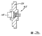
図1は、本発明に従う貯蔵ガスインフレータ10の1つの態様を示す。インフレータ10は、第1端62と第2端64を有する圧力容器12を含む。図1および図4を参照すると、第1の態様は、実質的に円筒形の金属インフレータボディを有する細長い容器12を含む。しかし、代替的なインフレータボディの種類およびデザインも、本発明の範囲から逸脱することなく使用可能であることが理解されるべきである。容器12は、長さ方向の中心軸Aおよび容器12の一端に形成された開口部60を有する。圧力容器は、打抜き、押し出し、ダイカスト、または他の金属成形により製造でき、例えば炭素鋼またはステンレス鋼から製造できる。
DETAILED DESCRIPTION OF THE INVENTION FIG. 1 illustrates one embodiment of a
点火装置18は、圧力容器12に、点火装置18が圧力容器12の内部と点火可能または動作可能に連通するように固定される。示された態様においては、点火装置キャップアセンブリー16(図3にも表示)は、点火装置18およびキャップ20を含む。点火装置キャップアセンブリー16は、中心軸Aに沿って配置され、圧力容器12に設けられた開口部を密封する。点火装置18は、当分野に既知の方法で形成することができる。例示の点火装置構成物は米国特許第6,009,809号に記載されており、本明細書に参照として組み込まれる。キャップ20は、打抜き、押し出し、ダイカスト、または他の金属成形により製造することができ、そして例えば炭素鋼またはステンレス鋼から製造できる。キャップ20は、キャップ20と容器12とのガス密封シールを保証するのに十分な方法で、溶接および/または圧接またはその他で圧力容器20に固定してもよい。
The
図1を再度参照すると、有孔のガス発生剤用筐体22は、ガス発生剤組成物14を閉じ込めるため、およびガス発生剤組成物14の圧力容器12の長さにわたる比較的迅速な伝播を促進するために、設けられる。図5は、図1に示されるガス発生剤用筐体22の詳細な図である。筐体22は、第1端68と第2端70を規定する、細長い、実質的に円筒形のボディ23および、その中にガス発生剤14を収納するための内部空洞を有する。筐体22はまた複数の開口24を含み、これらは、必ずしもその必要はないがその長さに沿って実質的に均等間隔で配置されるのが好ましく、これによって容器12に貯蔵された加圧ガスと、筐体の内部空洞との間の均等な流体連通を可能にする。開口24は、図1および図5に示されるものとはその数またはデザインが異なってもよい。ガス発生剤チューブ22は、例えば、金属薄板からロール成形により形成され、次に孔をあけることができる。
Referring again to FIG. 1, the perforated gas
筐体22は、容器12内に配置され、圧力容器の中心軸Aに沿って延びる。第1端68は、点火装置18と筐体22の内部空洞との間の流体連通を可能とするように配置される。下記の破裂可能シール30は、第2端70に隣接して固定され、これによって、容器開口部60においてガス密封シールを形成する。
The
図1を再度参照すると、ある量のガス発生剤組成物14は、ガス発生剤用筐体22の内部空洞内に配置される。ガス発生剤14は、開いたまたは有孔の筐体22内に入れられ、圧力容器12内の加圧ガスと定常的に流体連通する。図1に示す態様においては、ガス発生剤14は、第1端14aと第2端14bとを有する細長いストランドとして形成される。ストランド14は、筐体22および圧力容器12の長さに沿って縦長に延びる。ストランド14の第1端14aは、筐体22の第1端68に配置され、それによって、点火装置18と動作可能に連通する。ストランドの第2端14bは、シール30に隣接して配置され、それによって、圧力容器12の内部の長さにわたるガス発生を促進する。図1に示す態様においては、推進剤ストランド14の連続する外表面領域は、推進剤ストランド14の長さにわたる比較的迅速な燃焼の伝播を促進する。
Referring again to FIG. 1, an amount of the
好適なガス発生剤組成物は、例えば、本出願人の同時係属中の米国特許出願第09/664,130号に開示されており、この出願は本明細書に参照として組み込まれる。他の好適なガス発生剤には、限定はされないが、米国特許第5,035,757号、第6,210,505号、第5,872,329号が含まれ、これらも本明細書に参照としてその全体が組み込まれる。一般に、任意の既知の火薬ガス発生剤が、任意の形態において、車両乗員保護システム内での利用が認識されており、例えば圧力容器12内で用いることができる。
Suitable gas generant compositions are disclosed, for example, in Applicant's co-pending US patent application Ser. No. 09 / 664,130, which is hereby incorporated by reference. Other suitable gas generants include, but are not limited to, US Pat. Nos. 5,035,757, 6,210,505, 5,872,329, which are also incorporated herein by reference in their entirety. In general, any known explosive gas generant is recognized for use in a vehicle occupant protection system in any form and can be used, for example, in the
固体ガス発生剤は圧力容器12内に収納されるため、そして高圧ガスと連続的に流体接触または連通しているため、最適燃焼状態はガス発生剤の点火により直ちに利用可能となる。これらの条件のもとで、周囲圧力において効率的に燃焼する固体ガス発生剤は、圧力容器内の比較的高い圧力においてもより高い燃焼速度(burn rate)を示す。このため、これらのガス発生剤は、本発明に所望される迅速なガス発生剤燃焼速度を達成するために特に好適である。
換言すると、シリコーンを燃料として用いるガス発生剤の群は、本発明で用いるのに特に好適であると考えられている。これらのガス発生剤はさらに、金属および非金属過塩素酸塩、例えば、過塩素酸カリウム、過塩素酸リチウム、過塩素酸アンモニウムを含む群から選択される酸化剤を含む。所望の場合は、これらのガス発生剤は、金属炭酸塩、金属重炭酸塩、金属シュウ酸塩、および金属水酸化物を含む群から選択される冷却剤をさらに含んでもよい。
Because the solid gas generant is housed in the
In other words, the group of gas generants that use silicone as a fuel is considered particularly suitable for use in the present invention. These gas generants further comprise an oxidizing agent selected from the group comprising metallic and non-metallic perchlorates such as potassium perchlorate, lithium perchlorate, ammonium perchlorate. If desired, these gas generants may further comprise a coolant selected from the group comprising metal carbonates, metal bicarbonates, metal oxalates, and metal hydroxides.
本発明のさらに他の側面において、燃料として少なくとも1つのシリコーンポリマー(有機シロキサンポリマー)、および少なくとも1つの酸化剤を含む組成物は、周囲圧力および周囲圧力において許容可能な燃焼温度で燃焼する。所望により、これらの組成物は、金属塩および/または塩基を含む少なくとも1種の冷却剤成分を含むことができる。これらの組成物は周囲圧力において燃焼を持続する性質を有するため、圧力容器12内の高圧ガスの高圧力環境で用いられる場合、これらの点火性および燃焼性は増強される。従って、このガス発生剤の組成物の燃焼もまた、既知の、例えば複数または二重チャンバーハイブリッドインフレータと比べて、比較的迅速な燃焼反応に貢献する。
In yet another aspect of the invention, a composition comprising at least one silicone polymer (organosiloxane polymer) as a fuel and at least one oxidant burns at ambient pressure and an acceptable combustion temperature at ambient pressure. If desired, these compositions can include at least one coolant component including a metal salt and / or a base. Since these compositions have the property of sustaining combustion at ambient pressure, their ignitability and flammability are enhanced when used in a high pressure environment of high pressure gas in the
シリコーンは、交互のシリコンおよび酸素原子であって種々の有機基(または官能基)がシリコンに付着したものからなる構造に基づく、多数のシロキサンポリマーの群の任意のものとして定義される。この基にはメチル、メトキシおよびアミノを含む基が含まれるが、これらに限定はされない。
本明細書中の用語「シリコーン」は、一般的な意味として理解される。Hawleyは、シリコーン(有機シロキサン)を、交互のシリコンおよび酸素原子であって種々の有機基(または官能基)がシリコンに付着したものからなる構造に基づくシロキサンポリマーの多数の群の任意のものとして記述している:

The term “silicone” herein is understood in a general sense. Hawley describes silicone (organosiloxane) as any of a number of groups of siloxane polymers based on a structure consisting of alternating silicon and oxygen atoms with various organic groups (or functional groups) attached to the silicon. Describes:
または、シリコーンは式2に示されるように、より一般的に表すこともできる:
式中「n」は複数の重合基またはカッコ内に与えられる分子の一部を示し、シリコンに付着した有機基を含む。
シリコーンの例は、米国特許第5,589,662号、第5,610,444号および第5,700,532号、および、Technology of polymer compounds and energetic materials, Fraunhofer-Institut fur Chemische Technologie (ICT), 1990に記載されたものを含み、各参照文献および資料は本明細書に参照として組み込まれる。
In the formula, “n” represents a plurality of polymer groups or a part of a molecule given in parentheses and includes an organic group attached to silicon.
Examples of silicones include those described in U.S. Pat. Documents and materials are incorporated herein by reference.
本発明の好ましいガス発生剤組成物は、好ましくはシリコーンを燃料として含む。シリコーン燃料成分は、ガス発生剤組成物の重量の約10〜25%で提供される。金属および非金属過塩素酸塩を含む群から選択される1種または2種以上の一次酸化剤が提供される。所望により、二次酸化剤は、これらに限定されないが、相安定化硝酸アンモニウム、硝酸アンモニウム、硝酸カリウム、および硝酸ストロンチウムを含む。換言すれば、二次酸化剤は金属および非金属の塩素酸塩、酸化物、硝酸塩および亜硝酸塩を含む群、または他の既知の酸化剤から選択することができる。全酸化剤成分は、ガス発生剤組成物重量の約30〜85%で提供される。 A preferred gas generant composition of the present invention preferably comprises silicone as a fuel. The silicone fuel component is provided at about 10-25% of the weight of the gas generant composition. One or more primary oxidants selected from the group comprising metal and non-metal perchlorates are provided. Optionally, secondary oxidants include, but are not limited to, phase-stabilized ammonium nitrate, ammonium nitrate, potassium nitrate, and strontium nitrate. In other words, the secondary oxidant can be selected from the group comprising metal and non-metal chlorates, oxides, nitrates and nitrites, or other known oxidants. The total oxidizer component is provided at about 30-85% of the gas generant composition weight.
所望により、冷却剤は、金属炭酸塩、金属シュウ酸塩、金属重炭酸塩、および金属水酸化物を含む群から選択され、ガス発生剤組成物重量の約1〜30%で提供される。「金属」は、アルカリ金属、アルカリ土類金属、および遷移金属として定義される。冷却剤の例は、これらに限定されないが、炭酸ストロンチウム、炭酸マグネシウム、炭酸カルシウム、炭酸カリウム、シュウ酸ストロンチウム、および水酸化マグネシウムを含む。
一般に、成分を加える順序は、それらが均一に混合される限り重要ではない。他の既知の湿式および乾式混合法も用いることができる。混合が完了すると、ガス発生剤成分は、細長い突き出し形態、球粒、板状、または顆粒などの特定の形に押し出しまたは成形される。
Optionally, the coolant is selected from the group comprising metal carbonate, metal oxalate, metal bicarbonate, and metal hydroxide and is provided at about 1-30% of the gas generant composition weight. “Metal” is defined as alkali metal, alkaline earth metal, and transition metal. Examples of coolants include, but are not limited to, strontium carbonate, magnesium carbonate, calcium carbonate, potassium carbonate, strontium oxalate, and magnesium hydroxide.
In general, the order in which the ingredients are added is not critical as long as they are mixed uniformly. Other known wet and dry mixing methods can also be used. When mixing is complete, the gas generant component is extruded or molded into a specific shape, such as an elongated extrusion form, a sphere, plate, or granule.
表1に、本発明に用いるのに特に好適なガス発生剤組成物を例示する。この表に示されるように、シリコーンおよび過塩素酸塩酸化剤からなる組成物は、1インチ/秒以上の、迅速で持続する燃焼速度(3000psi)を有する。これらの燃焼特性は、燃焼速度が約0.4インチ/秒以上である周囲圧力において観察された。それにも拘わらず、燃焼温度は比較的高い。例2および例3を参照されたい。しかし、金属炭酸塩などの冷却剤が加えられる場合は、場合によっては温度は大幅に低下する。例えば例17、21および24を参照されたい。 Table 1 illustrates gas generator compositions that are particularly suitable for use in the present invention. As shown in this table, the composition consisting of silicone and perchlorate oxidant has a rapid and sustained burning rate (3000 psi) of 1 inch / second or more. These combustion characteristics were observed at ambient pressures where the burning rate was about 0.4 inches / second or higher. Nevertheless, the combustion temperature is relatively high. See Example 2 and Example 3. However, when a coolant such as metal carbonate is added, in some cases the temperature drops significantly. See, for example, Examples 17, 21, and 24.
表1
(表1つづき)
(表1つづき)
ある量の比較的不活性の加圧ガスを、圧力容器12内に貯蔵する。本明細書において、用語「実質的に不活性」とは、圧力容器12に貯蔵された加圧ガスが、不完全な燃焼システムの場合には燃焼反応を維持できないことを意味すると理解される。例えば、加圧ガスは実質的に酸素を含まず、1種類の実質的に不活性な成分(例えばN2)、または2種または3種以上のかかる成分、例えばN2およびHe2から形成される混合物を含むことができる。特定の態様において、加圧ガスは、約95%のN2および約5%のHe2を含む。種々の他のガスおよびガス混合物、または割合を、本発明の範囲から逸脱することなく用いることができる。
A quantity of relatively inert pressurized gas is stored in the
圧力容器12に貯蔵される加圧ガスの量および、容器12に配置されるガス発生剤14の量は、起動時のインフレータ10の既定の性能特性を達成するために変えることができる。表2は、ガス発生剤14の貯蔵加圧ガスに対する割合の範囲の例を示す。
表2に示された値は例であり、限定するものとして解釈されるべきでないことが理解されるべきである。貯蔵ガスに対するガス発生剤の他の割合も、既定のデザインおよび性能目的を達成するために用いることができる。例えば、より小さなエアバッグまたはエアベルトの膨張には、大きいエアバッグと比べて比較的少量の膨張ガスが必要となる。この場合、用いるガス発生剤の質量は対応して低減することができる。同様に、比較的多量の膨張ガスが所望される場合は、用いるガス発生剤の質量は、対応して増加することができる。代替的に、貯蔵ガスとガス発生剤の両方の量を、所望量の膨張ガスを生成するために調節することができる。 It should be understood that the values shown in Table 2 are examples and should not be construed as limiting. Other ratios of gas generant to stored gas can also be used to achieve the predetermined design and performance objectives. For example, inflating a smaller airbag or airbag requires a relatively small amount of inflation gas compared to a larger airbag. In this case, the mass of the gas generating agent used can be correspondingly reduced. Similarly, if a relatively large amount of inflation gas is desired, the mass of gas generant used can be correspondingly increased. Alternatively, the amount of both stored gas and gas generant can be adjusted to produce the desired amount of inflation gas.
フィルターをインフレータデザイン中に組み込んで、ガス発生剤14の燃焼によって生成されたガスからの粒子状物質をフィルタリングすることができる。一般に、フィルターは、ガス発生剤14と圧力容器12に貯蔵された加圧ガスとの間に配置される。1つの態様において(示されず)、フィルターは筐体22の内部空洞に、ガス発生剤14と開口24の間に配置される。他の態様において、フィルター74は、筐体22の外部に、開口24と加圧ガスの間に配置される。この態様において、フィルター74は、筐体22から間隔をおいて配置するか、またはフィルターは筐体22の外表面上に配置して、筐体22から開口24を介して排出される燃焼ガスの流れを受け入れることができる。
A filter can be incorporated into the inflator design to filter particulate matter from the gas produced by the combustion of the
フィルター74は、ガス発生剤燃焼生成物をフィルタリングするために当分野に知られている、種々の材料の1つから形成することができる(例えば、炭素繊維メッシュまたはシート)。または、フィルター74は、任意の既知の供給業者、例えばWayne Wire Cloth Products, Inc.(Bloomfield Hills, Michigan)などから入手することができる。フィルターシートは、ガス発生剤用筐体22の外壁の内部を覆うよう配置および固定することができる。筐体の外表面に適用する場合は、フィルターシートは外表面に、ガス発生剤の燃焼により筐体22内に生成された内部圧力においても開口24の被覆を維持するのに十分な様式で、固定すべきである。例えば、フィルターシートは筐体22に、筐体を被覆するフィルターシートの周りにワイヤーを巻きつけることにより、または、フィルターシートを筐体の周りにクランプで締め付けることにより、固定することができる。
The
図1および図2を参照すると、キャップ15は圧力容器12の開口部60を覆うように配置する。キャップ15は、内部チャンバー71を規定し、その中に形成され、周縁部に均等間隔で配置された複数のオリフィス72を有し、内部チャンバー71とキャップの外部との間の流体連通を可能とし、圧力容器からキャップ内部チャンバーに受け入れられたガスの、多方向への拡散を可能とする。キャップ15は、打抜き、押し出し、ダイカスト、または他の金属成形により製造することができ、そして例えば炭素鋼またはステンレス鋼から製造できる。
1 and 2, the
バーストディスク(burst disk)30の形状の破裂可能な流体密封シールは、圧力容器開口部60を密封するよう配置されて、圧力容器12内の加圧ガスを維持する。バーストディスク30は、キャップ15に、ガス発生剤第2端14bに隣接して固定され、これによって通常動作状態中に、チャンバー71に流体が流れる込むのを防ぐ。ディスク30は加圧ガスとキャップ15の内部チャンバー71の間の流体密封バリアを形成する。図6は、本発明で用いるのに好適な流体密封シールの例の詳細図を示す。種々のディスク、ホイル、フィルム等を、容器12内に密封するガスの圧力に応じて、およびインフレータ10の所望の性能特性に応じて、バーストディスク30を形成するために用いることができる。例えば、比較的容易に破壊される材料から、および/または構造を有して、製造されたディスクを用いることができる。さらに、ガス発生剤筐体22の第2端70はディスク30に隣接しているため、ディスクはある程度の構造支持体および位置的安定性を、筐体22の端70に対して提供する。
A rupturable fluid tight seal in the form of a
図1および図5を参照すると、筐体22に結合したカップ25は、点火装置18を囲んでよく、カップ25の流体密封内部を規定し、ガス発生器の起動によりガス発生剤14と点火装置18の両方と流体連通する。図5は、筐体22に結合したカップ25のより詳細な図を示す。カップ25は、ガス発生剤の第1端14aに隣接して配置される。点火装置18の起動の間、カップ25は存在する中間のガス圧力に対応することができ、推進剤ストランド14の点火を促進する。ある量のブースター推進剤(示されず)は、カップの内部に配置することができ、当分野で知られた様式で、ガス発生剤14の燃焼を促進する。図1および図5に見られるように、カップ25は、ガス発生剤用筐体22に隣接して配置され固定された一方の端が細くなっている。この先細形状により、点火装置18の起動時に、点火装置18からガス発生剤へと、燃焼生成物の流れを導くように機能する。カップ25は、ガス発生剤用筐体22と一体化して形成することができる。カップ25は、打抜き、押し出し、ダイカスト、または他の金属成形により製造することができ、そして例えば炭素鋼またはステンレス鋼から製造できる。
Referring to FIGS. 1 and 5, a
圧力容器12は、当分野に知られた幾つかの方法の任意の1つを用いて加圧および密封することができる。容器12を加圧および密封する1つの例示の方法は、米国特許第6,488,310号に記載されており、これは本明細書に参照として組み込まれる。この方法を用いて、圧力容器12は、圧力容器の1端に形成された突起(示されず)に形成された小さな孔から充填する。次に孔は、シールピンまたは他の好適な方法により閉じる。
衝突事象の際には、衝突センサー(示されず)からの信号が点火装置18に伝達され、これによって点火装置18を起動し、推進剤14に点火する。カップ25は、点火装置18からの燃焼生成物の流れを、筐体22の第1端68のガス発生剤ストランド14へと導く。推進剤14の点火により、筐体22の内部に比較的迅速に燃焼ガスが生成される。推進剤ストランド14の燃焼が、第1端14aから第2端14bへと進むにつれて、ガスは、筐体22の開口24を通って、圧力容器12の内部へと排出される。
The
In the event of a collision event, a signal from a collision sensor (not shown) is transmitted to the
好ましい態様の他の側面において、ガス発生剤14の燃焼によって生成される火炎の前部が、推進剤第1端14aから推進剤第2端14bへと迅速に伝播するにつれて、点火装置18とシール30の間の加圧ガスは、容器12の長さに沿って熱い燃焼生成物に暴露され、ガス発生剤用筐体22と容器12が実質的に長さ方向に同じ広がりを有するため、実質的に均一に熱せられる。従って、圧力容器12の全体でガスが均一に熱せられることにより、比較的迅速な圧力形成がなされ、エアバッグなど関連するデバイスの迅速な起動がもたらされる。燃焼ガスからの圧力の増加は、容器12の圧力下で既に貯蔵され熱せられたガスの上昇圧力と組み合わさって、バーストディスク30の破壊を引き起こす。貯蔵された膨張ガスは、次に容器12からキャップ15の内部チャンバー71へ流れ出し、少なくとも1つのガス出口オリフィス72から流れ出て、関連する車両エアバッグを膨張させる。
In another aspect of the preferred embodiment, the
火薬ガス発生剤が高圧ガスの圧力容器内に収納され、高圧ガスと連続的に流体接触または連通しているため、該ガス発生剤が点火時に遅延なしで即座に燃焼することに対する、最適条件が存在する。従って、そうでない場合に通常起こるより比較的速い、ガス発生剤14の燃焼速度(burning rate)が得られる。推進剤の高い燃焼速度および温度は一般に、衝撃波と貯蔵ガス圧力の迅速な増加を引き起こし、バーストディスク30を破壊する。従って、インフレータ10の点火/起動から、ガスが放出されてエアバッグの膨張に利用可能となるまでに必要な時間が最小化される。また、ガス発生剤が圧力容器内に配置され、比較的高い貯蔵膨張ガスの圧力に暴露されているため、より高い圧力でより効率的に燃焼する火薬ガス発生剤の使用が可能となる。さらに、本発明は、火薬ガス発生剤のための、分離された密封式燃焼チャンバーの必要性を取り除く。これにより、製造の複雑さおよびインフレータのコストを低減する。さらに、前述したように、ガス発生剤を貯蔵膨張ガスチャンバーに配置して、ガス発生剤を高い膨張ガス圧力に暴露することで、車両乗員保護システムの膨張式部品を膨張するのに必要な時間を最小化することができる。
Since the explosive gas generant is housed in a high pressure gas pressure vessel and is in continuous fluid contact or communication with the high pressure gas, the optimum condition for the gas generant to burn immediately without delay upon ignition is Exists. Accordingly, a burning rate of the
図7は、筐体の第2端がシールに隣接した支持部材38に固定されている、本発明の代替的な態様を示す。
図8は、ガス発生システムが、エアバッグ40および点火装置18と電子的に通信する衝突センサーパッケージ42を含む車両乗員保護システムである、本発明のガス発生システムの例の模式図である。
FIG. 7 illustrates an alternative embodiment of the present invention where the housing second end is secured to a support member 38 adjacent to the seal.
FIG. 8 is a schematic diagram of an example of the gas generation system of the present invention, where the gas generation system is a vehicle occupant protection system that includes a crash sensor package 42 that is in electronic communication with the
要約すると、本発明は以下を特徴とする:第1端62および第2端64を含む密封圧力容器12を含むガス発生システム30であって、圧力容器12は既定圧力52の加圧ガス50を含み;圧力容器12内に収納された有孔筐体22も、既定圧力52で加圧されており、筐体22の密封されていない孔を与えられ、ここで筐体は、例えばエアバッグインフレータにおいて用いるのに好適なガス発生剤48を収納しており;有孔筐体22は、第1端62に隣接して固定された第3端68と、第2端64に隣接して固定された第4端70とを含み、これによって圧力容器12および筐体22の長さにわたって構造的補強を提供し;点火装置アセンブリ16は、第1端62に固定され、ガス発生器システムの起動時にガス発生剤48と動作可能に連通し;所望により、筐体22は、図に示されるように点火装置アセンブリ16に固定され、これによって筐体22の第3端68を圧力容器12の第1端62に固定しており;そして少なくとも1つのガス出口オリフィス46が、密封圧力容器に形成されており、点火装置18の起動時に、密封圧力容器12が開かれてガス出口オリフィス46を通ってガスが放出される。
In summary, the present invention is characterized by the following: a
前記議論は本発明を限定すると解釈されるべきでなく、そして開示された態様に対して多くの変更が、添付の特許請求の範囲に定義された本発明の範囲から逸脱することなく可能であることが、理解されるべきである。上記記載は従って、本発明の範囲を限定することは意図しない。 The foregoing discussion should not be construed as limiting the invention, and many modifications to the disclosed embodiments are possible without departing from the scope of the invention as defined in the appended claims. It should be understood. The above description is therefore not intended to limit the scope of the invention.
Claims (12)
第1端(62)および第2端(64)、およびその中の開口部(60)を有する、圧力容器(12);
前記圧力容器(12)の開口部(60)を密封するように配置された、破裂可能なシール(30);
前記圧力容器(12)に貯蔵された、ある量の非反応性の加圧ガス;
前記圧力容器(12)に固定され、圧力容器(12)の内部と流体連通する、点火装置(18);
前記圧力容器(12)の内部に配置された有孔のガス発生剤用筐体(22)であって、前記筐体(22)は、ある長さ、第3端(68)、第4端(70)を有し、そして内部空洞を規定しており、第3端(68)は、前記点火装置(18)と前記内部空洞との間の流体連通を可能にするように配置され、第4端(70)は前記シール(30)と隣接しており、前記有孔筐体(22)は、その長さに沿って均等な間隔をおいて複数の開口(24)を有し、前記加圧ガスと前記内部空洞との間の流体連通を可能にしている、前記筐体(22);および
前記内部空洞内に収納され、前記筐体(22)の長さ方向に沿って延びている、ある量のガス発生剤組成物(48);
を含む、前記インフレータ(10)。An inflator (10) for use in an inflatable vehicle occupant protection system comprising:
A pressure vessel (12) having a first end (62) and a second end (64) , and an opening (60) therein;
A rupturable seal (30) arranged to seal the opening (60 ) of the pressure vessel (12 ) ;
A quantity of non- reactive pressurized gas stored in the pressure vessel (12) ;
Secured to said pressure vessel (12), in fluid communication with the interior of the pressure vessel (12), an ignition device (18);
A perforated gas generating agent casing (22) disposed inside the pressure vessel (12), the casing (22) having a certain length, a third end (68) , a fourth end (70) and defining an internal cavity, the third end (68) is arranged to allow fluid communication between the ignition device (18) and the internal cavity, The four ends (70) are adjacent to the seal (30), and the perforated housing (22) has a plurality of openings (24) at equal intervals along its length, Housing (22) allowing fluid communication between a pressurized gas and the internal cavity; and housed within the internal cavity and extending along a length of the housing (22) An amount of gas generant composition (48) ;
Said inflator (10) .
ガスを発生するためのガス発生器;
前記ガス発生器内の圧力容器(12);
前記圧力容器(12)内の、非反応性の加圧ガス;
前記加圧ガスを流出させるための、前記圧力容器(12)に形成されたオリフィス;
前記圧力容器(12)のオリフィスを密封するための破裂可能なシール(30);
前記ガス発生器内の、前記シール(30)に隣接したガス発生剤用筐体(22)、ここで該筐体(22)は、その長さに沿って均等な間隔をおいて複数の開口(24)を有する;および
前記ガス発生剤用筐体(22)内のガス発生剤(48)であって、燃焼して、前記加圧ガスと連通する燃焼生成物を生成する、前記ガス発生剤(48);
を含む、前記ガス発生システム。A gas generation system,
Gas generator for generating gas;
A pressure vessel (12) in the gas generator;
A non- reactive pressurized gas in the pressure vessel (12) ;
An orifice formed in the pressure vessel (12) for allowing the pressurized gas to flow;
A rupturable seal (30) for sealing the orifice of the pressure vessel (12 ) ;
A gas generant housing (22) in the gas generator adjacent to the seal (30) , wherein the housing (22) has a plurality of openings at equal intervals along its length. And (24) a gas generating agent (48) in the gas generating agent casing (22) , wherein the gas generating generates a combustion product in communication with the pressurized gas. Agent (48) ;
The gas generation system comprising:
Applications Claiming Priority (3)
| Application Number | Priority Date | Filing Date | Title |
|---|---|---|---|
| US50357703P | 2003-09-17 | 2003-09-17 | |
| US60/503,577 | 2003-09-17 | ||
| PCT/US2004/030722 WO2005028252A2 (en) | 2003-09-17 | 2004-09-17 | Pyrotechnic stored gas inflator |
Publications (3)
| Publication Number | Publication Date |
|---|---|
| JP2007513818A JP2007513818A (en) | 2007-05-31 |
| JP2007513818A5 JP2007513818A5 (en) | 2007-11-08 |
| JP4823907B2 true JP4823907B2 (en) | 2011-11-24 |
Family
ID=34375369
Family Applications (1)
| Application Number | Title | Priority Date | Filing Date |
|---|---|---|---|
| JP2006527106A Expired - Fee Related JP4823907B2 (en) | 2003-09-17 | 2004-09-17 | Gunpowder storage gas inflator |
Country Status (4)
| Country | Link |
|---|---|
| US (1) | US7431335B2 (en) |
| EP (1) | EP1667873A2 (en) |
| JP (1) | JP4823907B2 (en) |
| WO (1) | WO2005028252A2 (en) |
Families Citing this family (41)
| Publication number | Priority date | Publication date | Assignee | Title |
|---|---|---|---|---|
| US7094296B1 (en) * | 1999-09-16 | 2006-08-22 | Automotive Systems Laboratory, Inc. | Gas generants containing silicone fuels |
| US7306856B2 (en) * | 2000-07-17 | 2007-12-11 | Fujifilm Corporation | Light-emitting element and iridium complex |
| JP4280161B2 (en) * | 2003-12-22 | 2009-06-17 | ダイセル化学工業株式会社 | Gas generator for airbag |
| US20050230950A1 (en) * | 2004-04-20 | 2005-10-20 | Trw-Vehicle Safety Systems Inc. | Inflator with stamped end cap |
| US7654565B2 (en) * | 2005-06-02 | 2010-02-02 | Automotive Systems Laboratory, Inc. | Gas generating system |
| US8496266B2 (en) * | 2005-06-02 | 2013-07-30 | Tk Holdings, Inc. | Gas generating system |
| US20110057429A1 (en) * | 2005-07-29 | 2011-03-10 | Hordos Deborah L | Gas generating system and composition |
| US8376400B2 (en) * | 2006-04-21 | 2013-02-19 | Tk Holdings, Inc. | Gas generating system |
| JP2008037415A (en) * | 2006-06-19 | 2008-02-21 | Tk Holdings Inc | Gas generating system |
| US20080197612A1 (en) * | 2007-02-15 | 2008-08-21 | Kirchen James T | Dispersing tube |
| US20090114109A1 (en) * | 2007-11-01 | 2009-05-07 | Arc Automotive Inc. | Stamped and molded igniter body for airbag inflators |
| DE102007053101B4 (en) * | 2007-11-07 | 2024-05-16 | Zf Automotive Germany Gmbh | Gas generator and assembly with a gas generator |
| US7878535B2 (en) * | 2008-04-29 | 2011-02-01 | Arc Automotive, Inc. | Airbag inflator with adaptive valve |
| US7959185B2 (en) * | 2008-10-01 | 2011-06-14 | Autoliv Development Ab | Inflator bottle for combustible gas mixture |
| CN101970265B (en) † | 2009-05-11 | 2013-01-02 | 高田-彼得里公开股份有限公司 | Gas generator and method for inflating an airbag and airbag module |
| JP5436036B2 (en) * | 2009-05-12 | 2014-03-05 | 株式会社ダイセル | Gas generator |
| US8839871B2 (en) * | 2010-01-15 | 2014-09-23 | Halliburton Energy Services, Inc. | Well tools operable via thermal expansion resulting from reactive materials |
| JP5399935B2 (en) * | 2010-02-03 | 2014-01-29 | 株式会社ダイセル | Gas generator |
| US9321426B1 (en) | 2010-04-28 | 2016-04-26 | Tk Holdings, Inc. | Container for gas generant |
| US8474533B2 (en) | 2010-12-07 | 2013-07-02 | Halliburton Energy Services, Inc. | Gas generator for pressurizing downhole samples |
| US9010442B2 (en) | 2011-08-29 | 2015-04-21 | Halliburton Energy Services, Inc. | Method of completing a multi-zone fracture stimulation treatment of a wellbore |
| US9151138B2 (en) | 2011-08-29 | 2015-10-06 | Halliburton Energy Services, Inc. | Injection of fluid into selected ones of multiple zones with well tools selectively responsive to magnetic patterns |
| US9506324B2 (en) | 2012-04-05 | 2016-11-29 | Halliburton Energy Services, Inc. | Well tools selectively responsive to magnetic patterns |
| US9169705B2 (en) | 2012-10-25 | 2015-10-27 | Halliburton Energy Services, Inc. | Pressure relief-assisted packer |
| US9587486B2 (en) | 2013-02-28 | 2017-03-07 | Halliburton Energy Services, Inc. | Method and apparatus for magnetic pulse signature actuation |
| US9562429B2 (en) | 2013-03-12 | 2017-02-07 | Halliburton Energy Services, Inc. | Wellbore servicing tools, systems and methods utilizing near-field communication |
| US9284817B2 (en) | 2013-03-14 | 2016-03-15 | Halliburton Energy Services, Inc. | Dual magnetic sensor actuation assembly |
| US9752414B2 (en) | 2013-05-31 | 2017-09-05 | Halliburton Energy Services, Inc. | Wellbore servicing tools, systems and methods utilizing downhole wireless switches |
| US20150075770A1 (en) | 2013-05-31 | 2015-03-19 | Michael Linley Fripp | Wireless activation of wellbore tools |
| US9482072B2 (en) | 2013-07-23 | 2016-11-01 | Halliburton Energy Services, Inc. | Selective electrical activation of downhole tools |
| US9739120B2 (en) | 2013-07-23 | 2017-08-22 | Halliburton Energy Services, Inc. | Electrical power storage for downhole tools |
| CA2939043C (en) | 2014-03-24 | 2018-12-11 | Halliburton Energy Services, Inc. | Well tools having magnetic shielding for magnetic sensor |
| US9890604B2 (en) * | 2014-04-04 | 2018-02-13 | Owen Oil Tools Lp | Devices and related methods for actuating wellbore tools with a pressurized gas |
| JP6351439B2 (en) * | 2014-08-27 | 2018-07-04 | 日本化薬株式会社 | Gas generator |
| AU2014412711B2 (en) | 2014-11-25 | 2018-05-31 | Halliburton Energy Services, Inc. | Wireless activation of wellbore tools |
| JP6454143B2 (en) * | 2014-12-03 | 2019-01-16 | 株式会社ダイセル | Gas generator |
| US10054265B2 (en) * | 2016-11-29 | 2018-08-21 | Goodrich Corporation | System and method for a heated gas cylinder assembly |
| USD851763S1 (en) | 2016-12-29 | 2019-06-18 | Mathews Outdoor Products LLC | Fire starter lance |
| CN109915034B (en) * | 2017-12-13 | 2024-04-26 | 株洲飞马橡胶实业有限公司 | Offshore drilling rod device with rubber air spring capable of being continuously used |
| FR3139074A1 (en) * | 2022-08-25 | 2024-03-01 | Livbag Sas | Gas generator comprising propellant under pressure |
| FR3139073A1 (en) * | 2022-08-25 | 2024-03-01 | Livbag Sas | Gas generator with propellant stored under pressure |
Citations (8)
| Publication number | Priority date | Publication date | Assignee | Title |
|---|---|---|---|---|
| US3721456A (en) * | 1971-04-23 | 1973-03-20 | Gen Motors Corp | Multiple stage inflater |
| JPH05278554A (en) * | 1991-09-18 | 1993-10-26 | Trw Vehicle Safety Syst Inc | Vehicle occupant restraint |
| JPH0640304A (en) * | 1992-03-04 | 1994-02-15 | Imperial Chem Ind Plc <Ici> | Compound inflator |
| JPH08282427A (en) * | 1994-10-25 | 1996-10-29 | Oea Inc | Compact hybrid inflator |
| JPH11245760A (en) * | 1997-12-23 | 1999-09-14 | Trw Vehicle Safety Syst Inc | Inflator structure |
| JP2001191888A (en) * | 1999-06-18 | 2001-07-17 | Daicel Chem Ind Ltd | Retainer for gas generator |
| JP2001191889A (en) * | 1999-06-18 | 2001-07-17 | Daicel Chem Ind Ltd | Multi-stage inflatable hybrid inflator |
| JP2003081050A (en) * | 2001-09-12 | 2003-03-19 | Livbag Snc | Hybrid gas generator |
Family Cites Families (23)
| Publication number | Priority date | Publication date | Assignee | Title |
|---|---|---|---|---|
| US230882A (en) * | 1880-08-10 | Alexakdeb mackey | ||
| US3930666A (en) * | 1974-05-01 | 1976-01-06 | Specialty Products Development Corporation | Hybrid gas system for automobile passenger restraint system |
| US5109772A (en) * | 1991-01-22 | 1992-05-05 | Morton International, Inc. | Flash ignition system |
| US5351989A (en) * | 1992-11-30 | 1994-10-04 | Trw Vehicle Safety Systems Inc. | Inflator assembly |
| GB2277984B (en) * | 1993-05-12 | 1996-06-12 | Autoliv Dev | Improvements in or relating to a gas generator |
| US5364127A (en) * | 1993-06-11 | 1994-11-15 | Trw Inc. | Inflator assembly |
| US5516147A (en) * | 1994-10-12 | 1996-05-14 | Morton International, Inc. | Stamped metal toroidal hybrid gas generator with sliding piston |
| US5593180A (en) * | 1995-04-24 | 1997-01-14 | Trw Inc. | Dual chamber inflator for side impact air bag |
| US5655790A (en) * | 1995-06-06 | 1997-08-12 | Trw Vehicle Safety Systems Inc. | Air bag inflator |
| US6155600A (en) * | 1996-01-25 | 2000-12-05 | Reynolds; George L. | Safety air bag inflation device |
| US5868424A (en) * | 1996-03-06 | 1999-02-09 | Oea, Inc. | Substantially smoke-free and particulate-free inflator for inflatable safety restraint system |
| US5907120A (en) * | 1996-06-17 | 1999-05-25 | Hi Shear Technology Corporation | Inflator for vehicle air bags |
| US5762368A (en) * | 1996-06-20 | 1998-06-09 | Trw Vehicle Safety Systems Inc. | Initiator for air bag inflator |
| DE19653783A1 (en) * | 1996-12-21 | 1998-06-25 | Dynamit Nobel Ag | Hybrid gas generator for an airbag |
| US6368431B2 (en) * | 1997-11-12 | 2002-04-09 | Trw Inc. | Air bag inflator |
| US6007097A (en) * | 1998-06-09 | 1999-12-28 | Autoliv Asp, Inc. | Flammable gas initiated pyrotechnic inflator |
| US6296274B1 (en) * | 2000-02-11 | 2001-10-02 | Trw Inc. | Apparatus for inflating a side curtain |
| US6488310B1 (en) * | 2000-03-28 | 2002-12-03 | Daicel Chemical Industries, Ltd. | Hybrid inflator |
| WO2001083274A1 (en) * | 2000-05-02 | 2001-11-08 | Automotive Systems Laboratory, Inc. | Inflator |
| US20020073873A1 (en) * | 2000-12-15 | 2002-06-20 | Ulrich Bley | Gas generator for low-slag gas cartridges for motor vehicle safety |
| US6874814B2 (en) | 2002-06-13 | 2005-04-05 | Key Safety Systems, Inc. | Multiple stage inflator |
| US6976704B2 (en) * | 2003-01-30 | 2005-12-20 | Autoliv Asp, Inc. | Adaptive output airbag inflation device |
| US7192055B2 (en) * | 2003-11-13 | 2007-03-20 | Automotive Systems Laboratory, Inc. | Pyrotechnic linear inflator |
-
2004
- 2004-09-17 JP JP2006527106A patent/JP4823907B2/en not_active Expired - Fee Related
- 2004-09-17 WO PCT/US2004/030722 patent/WO2005028252A2/en not_active Ceased
- 2004-09-17 US US10/943,458 patent/US7431335B2/en not_active Expired - Fee Related
- 2004-09-17 EP EP04784562A patent/EP1667873A2/en not_active Withdrawn
Patent Citations (8)
| Publication number | Priority date | Publication date | Assignee | Title |
|---|---|---|---|---|
| US3721456A (en) * | 1971-04-23 | 1973-03-20 | Gen Motors Corp | Multiple stage inflater |
| JPH05278554A (en) * | 1991-09-18 | 1993-10-26 | Trw Vehicle Safety Syst Inc | Vehicle occupant restraint |
| JPH0640304A (en) * | 1992-03-04 | 1994-02-15 | Imperial Chem Ind Plc <Ici> | Compound inflator |
| JPH08282427A (en) * | 1994-10-25 | 1996-10-29 | Oea Inc | Compact hybrid inflator |
| JPH11245760A (en) * | 1997-12-23 | 1999-09-14 | Trw Vehicle Safety Syst Inc | Inflator structure |
| JP2001191888A (en) * | 1999-06-18 | 2001-07-17 | Daicel Chem Ind Ltd | Retainer for gas generator |
| JP2001191889A (en) * | 1999-06-18 | 2001-07-17 | Daicel Chem Ind Ltd | Multi-stage inflatable hybrid inflator |
| JP2003081050A (en) * | 2001-09-12 | 2003-03-19 | Livbag Snc | Hybrid gas generator |
Also Published As
| Publication number | Publication date |
|---|---|
| WO2005028252A3 (en) | 2008-10-30 |
| US20050110253A1 (en) | 2005-05-26 |
| EP1667873A2 (en) | 2006-06-14 |
| WO2005028252A2 (en) | 2005-03-31 |
| US7431335B2 (en) | 2008-10-07 |
| JP2007513818A (en) | 2007-05-31 |
Similar Documents
| Publication | Publication Date | Title |
|---|---|---|
| JP4823907B2 (en) | Gunpowder storage gas inflator | |
| EP1658204B1 (en) | Pyrotechnique side impact inflator | |
| JP3817233B2 (en) | Low-strength two-stage hybrid inflator | |
| JP2609404B2 (en) | Igniters and expanders | |
| US8419057B2 (en) | Gas generating system | |
| JP4167284B2 (en) | Multistage inflator | |
| JP2007523786A (en) | Gunpowder type linear inflator | |
| JP2007521999A (en) | Linear peroxide inflator | |
| JP3075466B2 (en) | Burning speed controller | |
| WO2001034516A2 (en) | Gas generation system | |
| WO2001025058A1 (en) | Hybrid inflator | |
| US6607214B2 (en) | Gas generation via indirect ignition | |
| JP5426062B2 (en) | Foam ignition materials used in automotive airbag inflator devices | |
| JP3218213B2 (en) | Gas generator for airbag and airbag device | |
| WO2006030967A1 (en) | Gas producer | |
| US20140305330A1 (en) | Gas Generating System | |
| WO2000002749A2 (en) | Heat source for airbag inflation gas generation via a dissociating material | |
| JP4994787B2 (en) | Gas generator | |
| WO2002062629A1 (en) | Gas generator | |
| JP2006168669A (en) | Gas generator for airbag | |
| JP2001219811A (en) | Gas generator for air bag and air bag device |
Legal Events
| Date | Code | Title | Description |
|---|---|---|---|
| A521 | Request for written amendment filed |
Free format text: JAPANESE INTERMEDIATE CODE: A523 Effective date: 20070918 |
|
| A621 | Written request for application examination |
Free format text: JAPANESE INTERMEDIATE CODE: A621 Effective date: 20070918 |
|
| A131 | Notification of reasons for refusal |
Free format text: JAPANESE INTERMEDIATE CODE: A131 Effective date: 20100427 |
|
| A601 | Written request for extension of time |
Free format text: JAPANESE INTERMEDIATE CODE: A601 Effective date: 20100727 |
|
| A602 | Written permission of extension of time |
Free format text: JAPANESE INTERMEDIATE CODE: A602 Effective date: 20100803 |
|
| A521 | Request for written amendment filed |
Free format text: JAPANESE INTERMEDIATE CODE: A523 Effective date: 20100827 |
|
| A131 | Notification of reasons for refusal |
Free format text: JAPANESE INTERMEDIATE CODE: A131 Effective date: 20101214 |
|
| A601 | Written request for extension of time |
Free format text: JAPANESE INTERMEDIATE CODE: A601 Effective date: 20110314 |
|
| A602 | Written permission of extension of time |
Free format text: JAPANESE INTERMEDIATE CODE: A602 Effective date: 20110322 |
|
| A601 | Written request for extension of time |
Free format text: JAPANESE INTERMEDIATE CODE: A601 Effective date: 20110414 |
|
| A602 | Written permission of extension of time |
Free format text: JAPANESE INTERMEDIATE CODE: A602 Effective date: 20110421 |
|
| A601 | Written request for extension of time |
Free format text: JAPANESE INTERMEDIATE CODE: A601 Effective date: 20110516 |
|
| A602 | Written permission of extension of time |
Free format text: JAPANESE INTERMEDIATE CODE: A602 Effective date: 20110523 |
|
| A521 | Request for written amendment filed |
Free format text: JAPANESE INTERMEDIATE CODE: A523 Effective date: 20110613 |
|
| TRDD | Decision of grant or rejection written | ||
| A01 | Written decision to grant a patent or to grant a registration (utility model) |
Free format text: JAPANESE INTERMEDIATE CODE: A01 Effective date: 20110809 |
|
| A01 | Written decision to grant a patent or to grant a registration (utility model) |
Free format text: JAPANESE INTERMEDIATE CODE: A01 |
|
| A61 | First payment of annual fees (during grant procedure) |
Free format text: JAPANESE INTERMEDIATE CODE: A61 Effective date: 20110907 |
|
| R150 | Certificate of patent or registration of utility model |
Free format text: JAPANESE INTERMEDIATE CODE: R150 |
|
| FPAY | Renewal fee payment (event date is renewal date of database) |
Free format text: PAYMENT UNTIL: 20140916 Year of fee payment: 3 |
|
| LAPS | Cancellation because of no payment of annual fees |