JP4802952B2 - X-ray equipment - Google Patents
X-ray equipment Download PDFInfo
- Publication number
- JP4802952B2 JP4802952B2 JP2006246953A JP2006246953A JP4802952B2 JP 4802952 B2 JP4802952 B2 JP 4802952B2 JP 2006246953 A JP2006246953 A JP 2006246953A JP 2006246953 A JP2006246953 A JP 2006246953A JP 4802952 B2 JP4802952 B2 JP 4802952B2
- Authority
- JP
- Japan
- Prior art keywords
- ray
- ray tube
- support arm
- fixing
- arm
- Prior art date
- Legal status (The legal status is an assumption and is not a legal conclusion. Google has not performed a legal analysis and makes no representation as to the accuracy of the status listed.)
- Expired - Fee Related
Links
- 238000003384 imaging method Methods 0.000 claims description 42
- 238000001514 detection method Methods 0.000 claims description 27
- 238000007689 inspection Methods 0.000 claims description 2
- 238000002594 fluoroscopy Methods 0.000 description 8
- 230000006835 compression Effects 0.000 description 6
- 238000007906 compression Methods 0.000 description 6
- 238000010586 diagram Methods 0.000 description 2
- 238000006073 displacement reaction Methods 0.000 description 2
- 230000000694 effects Effects 0.000 description 2
- 230000001678 irradiating effect Effects 0.000 description 1
- 238000002601 radiography Methods 0.000 description 1
Images


Landscapes
- Apparatus For Radiation Diagnosis (AREA)
Description
この発明は、支柱に昇降可能にキャリッジを設けるとともに、そのキャリッジに水平方向の軸心周りで回転可能に支持アームを設け、支持アームの長手方向の一端側に、被検者にX線を照射するX線管を設けるとともに、他端側に、X線管から照射されて被検者を透過したX線を受光するX線検出器を設けたX線撮影装置に関する。 In this invention, the carriage is provided with a carriage that can be moved up and down, a support arm is provided on the carriage so as to be rotatable around a horizontal axis, and the subject is irradiated with X-rays at one end in the longitudinal direction of the support arm. The present invention relates to an X-ray imaging apparatus in which an X-ray tube is provided and an X-ray detector that receives X-rays irradiated from the X-ray tube and transmitted through a subject is provided on the other end side.
この種のX線撮影装置では、X線管とX線検出器との距離を1.8〜2.0mにする胸部撮影等の遠距離撮影と、X線管とX線検出器との距離を1.0〜1.2m程度にして天板上の被検者に対して上下方向でX線管からのX線を照射するX線透視撮影とを行う場合がある。 In this type of X-ray imaging apparatus, long-distance imaging such as chest imaging in which the distance between the X-ray tube and the X-ray detector is 1.8 to 2.0 m, and the distance between the X-ray tube and the X-ray detector. In some cases, X-ray fluoroscopy is performed by irradiating the subject on the top board with X-rays from the X-ray tube in the vertical direction.
このような遠距離撮影と天板上の被検者に対するX線透視撮影の両方を、X線検出器を兼用して行うものとして、従来、次のようなものが知られている。
基台の主支柱の保持部に天板が保持され、その天板の下部に、天板に対して平行移動可能にX線像検出部が設けられている。別途、天板に対して平行移動可能に支柱が設けられ、その支柱に第1のX線管装置が固定保持されている。
天井走行部には第2のX線管装置が懸垂されている。
Conventionally, the following has been known as performing both such long-distance imaging and X-ray fluoroscopic imaging of a subject on a top board also using an X-ray detector.
A top plate is held by the holding portion of the main column of the base, and an X-ray image detection unit is provided below the top plate so as to be movable in parallel with the top plate. Separately, a support column is provided so as to be movable parallel to the top plate, and the first X-ray tube device is fixedly held on the support column.
A second X-ray tube device is suspended from the ceiling traveling unit.
上記構成により、第1のX線管装置を用いて天板上の被検者に対するX線透視撮影を行うときは、第1のX線管装置を天板の上方側に位置させるとともに、X線像検出部を天板の下方側に位置させ、第1のX線管装置とX線像検出部とを被検者の頭足方向に移動させるようにする。
一方、胸部撮影等のような遠距離撮影を行うときは、支柱を被検者の頭側または足側に退避させ、第2のX線管装置を、胸部に対する透視または撮影を行う位置に移動させるとともに、X線像検出部を第2のX線管装置に対向する透視または撮影する位置に移動させ、第2のX線管装置とX線像検出部とを組み合わせて透視または撮影を行うようになっている(特許文献1参照)。
On the other hand, when performing long-distance imaging such as chest imaging, the column is retracted to the subject's head side or foot side, and the second X-ray tube device is moved to a position where fluoroscopy or imaging is performed on the chest At the same time, the X-ray image detection unit is moved to a fluoroscopic or radiographic position facing the second X-ray tube device, and the second X-ray tube device and the X-ray image detection unit are combined to perform fluoroscopy or radiography. (See Patent Document 1).
ところが、上述従来例の場合、X線像検出部は兼用しているものの、X線管装置としては、第1および第2のX線管装置とそれぞれ専用のものを必要とする不都合があった。
そこで、X線管およびX線検出器のいずれをも兼用できるように構成するものとして、次のようなものが考えられている。
すなわち、図8の別の従来例の全体側面図に示すように、支柱01に昇降可能にキャリッジ02が設けられるとともに、キャリッジ02に水平方向の軸心周りで回転可能に支持アーム03が設けられている。
However, in the case of the above-described conventional example, although the X-ray image detection unit is also used, the X-ray tube device has a disadvantage that a dedicated device for each of the first and second X-ray tube devices is required. .
Then, the following is considered as a structure which can use both an X-ray tube and an X-ray detector.
That is, as shown in an overall side view of another conventional example of FIG. 8, a
支持アーム03に、被検者にX線を照射するX線管04と、X線管04から照射されて被検者を透過したX線を受光するX線検出器05それぞれが長手方向に移動可能に設けられている。支持アーム03の両端それぞれにスプロケット06が設けられるとともに、両スプロケット06にチェーン07が巻回され、チェーン07の下側部分に、X線管04を保持したX線管保持部材08が連結されるとともに、チェーン07の上側部分に、X線検出器05を保持したX線検出器保持部材09が連結されている。
また、支柱01を間にして、X線管04側とX線検出器05側とが重量的にバランスするように構成されている。
An
In addition, the
上記構成により、手動によって、X線管04側またはX線検出器05側の少なくともいずれか一方を支持アーム03に沿って移動させるに伴い、支柱01に対して、相反する方向に移動し、重量バランスを維持しながら、X線管04とX線検出器05との距離を変更し、遠距離撮影と天板上の被検者に対するX線透視撮影の両方を行うことができるようになっている。
According to the above configuration, when at least one of the
しかしながら、上述別の従来例の場合、次のような課題があった。
X線管とX線検出器とを移動させるために、スプロケットやチェーンが必要な上に、X線管およびX線検出器の両方を重量的にバランスしながら移動させるために構成が複雑化するとともに高価になる不都合があった。
However, another conventional example described above has the following problems.
In order to move the X-ray tube and the X-ray detector, a sprocket and a chain are required, and the configuration is complicated because both the X-ray tube and the X-ray detector are moved while being balanced in weight. In addition, there was an inconvenience of becoming expensive.
この発明は、上述のような事情に鑑みてなされたものであって、使用実態に着目して、簡単な構成で、かつ、安全に遠距離撮影と天板上の被検者に対するX線透視撮影の両方を行うことができるようにすることを目的とする。 The present invention has been made in view of the circumstances as described above, and pays attention to the actual situation of use, and has a simple configuration and can safely perform long-distance imaging and X-ray fluoroscopy for the subject on the top plate. The purpose is to be able to perform both shootings.
請求項1に係る発明は、上述のような目的を達成するために、次のような構成をとる。
すなわち、支柱に昇降可能にキャリッジを設けるとともに、前記キャリッジに水平方向の軸心周りで回転可能に支持アームを設け、前記支持アームの長手方向の一端側に、被検者にX線を照射するX線管を設けるとともに、他端側に、前記X線管から照射されて被検者を透過したX線を受光するX線検出器を設けたX線撮影装置において、
前記X線管のみを、そのX線照射方向に前記X線検出器に対して遠近変位可能に設け、前記支持アームを前記キャリッジに固定するアーム固定手段と、前記X線管が前記X線検出器に所定距離まで接近したことを検出する接近状態検出手段と、前記接近状態検出手段が所定距離までの接近を検出したことに応答して前記アーム固定手段の固定の解除を許容するアーム固定解除許容手段と、前記X線管が前記X線検出器に所定距離まで接近した状態で前記X線管を前記支持アームに固定するX線管固定手段と、前記支持アームが水平姿勢にあることを検出する水平検出手段と、前記水平検出手段が水平姿勢を検出したことに応答して前記X線管固定手段の固定の解除を許容するX線管固定解除許容手段とを備え、かつ、前記X線管が前記X線検出器に所定距離まで接近した状態で、前記支持アームの回転軸心を中心として前記X線管側と前記X線検出器側との重量がバランスするように構成してあることを特徴としている。
The invention according to claim 1 has the following configuration in order to achieve the above-described object.
That is, a carriage is provided on the column so as to be movable up and down, and a support arm is provided on the carriage so as to be rotatable around a horizontal axis, and X-rays are irradiated to the subject on one end side in the longitudinal direction of the support arm. In an X-ray imaging apparatus provided with an X-ray tube and provided with an X-ray detector on the other end side for receiving X-rays irradiated from the X-ray tube and transmitted through the subject,
Only the X-ray tube is provided to be displaceable in the X-ray irradiation direction with respect to the X-ray detector, and arm fixing means for fixing the support arm to the carriage, and the X-ray tube detects the X-ray. An approach state detecting means for detecting that the device has approached a predetermined distance, and an arm fixing release for permitting the unlocking of the arm fixing means in response to the approach state detecting means detecting an approach to the predetermined distance Permitting means , X-ray tube fixing means for fixing the X-ray tube to the support arm with the X-ray tube approaching the X-ray detector to a predetermined distance, and the support arm in a horizontal posture. Horizontal detection means for detecting, and X-ray tube fixing release permitting means for allowing the X-ray tube fixing means to be released in response to the horizontal detection means detecting a horizontal posture ; and X-ray inspection Vessel in a state of close to a predetermined distance, is characterized in that the weight of said X-ray tube side around the rotation axis and the X-ray detector side of the support arm is arranged to balance.
(作用・効果)
請求項1に係る発明のX線撮影装置の構成によれば、胸部撮影等のような遠距離撮影は、X線管からの照射方向を水平方向にした状態で行うものであり、一方、天板上の被検者に対するX線透視撮影は、X線管からの照射方向を鉛直方向や斜め方向などに調整しながら行うことに着目し、支持アームを水平姿勢にしてX線管とX線検出器との距離を離すときには、アーム固定手段により支持アームをキャリッジに固定した安定した状態でX線管のみをX線検出器に対して遠近変位させることができる。そして、X線管がX線検出器に所定距離まで接近した状態で、支持アームの回転軸心を中心としてX線管側とX線検出器側との重量がバランスする位置で、支持アームの固定を解除し、楽に支持アームを回転させ、X線管からの照射方向を鉛直方向や斜め方向など所望の方向に調整し、天板上の被検者に対するX線透視撮影を行うことができる。また、支持アームを水平姿勢にした状態でのみ、支持アームをキャリッジに固定した状態で、X線管をX線検出器に対して遠近変位させることができる。
(Action / Effect)
According to the configuration of the X-ray imaging apparatus of the first aspect of the invention, long-distance imaging such as chest imaging is performed in a state where the irradiation direction from the X-ray tube is in the horizontal direction. Focusing on X-ray fluoroscopy for the subject on the plate while adjusting the irradiation direction from the X-ray tube in the vertical direction or the oblique direction, the X-ray tube and the X-ray are set with the support arm in a horizontal posture. When the distance from the detector is increased, only the X-ray tube can be displaced relative to the X-ray detector in a stable state in which the support arm is fixed to the carriage by the arm fixing means. Then, with the X-ray tube approaching the X-ray detector to a predetermined distance, the weight of the X-ray tube side and the X-ray detector side is balanced around the rotation axis of the support arm. The fixation can be released, the support arm can be easily rotated, the irradiation direction from the X-ray tube can be adjusted to a desired direction such as a vertical direction or an oblique direction, and X-ray fluoroscopic imaging of the subject on the top can be performed. . In addition, the X-ray tube can be displaced relative to the X-ray detector with the support arm fixed to the carriage only when the support arm is in a horizontal posture.
したがって、使用実態に着目して、スプロケットやチェ−ンなどを使用することなく、簡単な構成で、遠距離撮影と天板上の被検者に対するX線透視撮影の両方を行うことができる。しかも、X線管をX線検出器に対して遠近変位するときに支持アームが不測に回転することを回避でき、遠距離撮影を安全に行うことができる。また、支持アームを回転するときに、不測にX線管がX線検出器に対して遠近変位することを回避でき、安全に支持アームおよびX線管を手動で変位操作しながら遠距離撮影と天板上の被検者に対するX線透視撮影の両方を行うことができる。 Therefore, paying attention to the actual condition of use, it is possible to perform both long-distance imaging and X-ray fluoroscopic imaging of the subject on the top board with a simple configuration without using sprockets or chains. In addition, the support arm can be prevented from rotating unexpectedly when the X-ray tube is displaced from the X-ray detector, and long-distance imaging can be performed safely. In addition, when the support arm is rotated, it is possible to avoid unexpected displacement of the X-ray tube relative to the X-ray detector, and it is possible to perform long-distance imaging while safely displacing the support arm and the X-ray tube manually. Both X-ray fluoroscopic imaging of the subject on the top board can be performed.
また、請求項2に係る発明は、
請求項1に記載のX線撮影装置において、
前記アーム固定解除許容手段が固定の解除を許容した状態で操作することにより、前記アーム固定手段の固定を解除する回転操作スイッチと、前記X線管固定解除許容手段が固定の解除を許容した状態で操作することにより、前記X線管固定手段の固定を解除するX線管移動操作スイッチとを備えて構成する。
The invention according to
The X-ray imaging apparatus according to claim 1,
Rotation operation switch for releasing the fixation of the arm fixing means by operating in a state where the arm fixing release allowing means permits the release of the fixing, and the X-ray tube fixing release allowing means allowing the release of the fixation And an X-ray tube moving operation switch for releasing the fixation of the X-ray tube fixing means.
(作用・効果)
請求項2に係る発明のX線撮影装置の構成によれば、アーム固定解除許容手段が固定の解除を許容した状態で回転操作スイッチを操作することにより、アーム固定手段の固定を解除することができる。また、X線管固定解除許容手段が固定の解除を許容した状態でX線管移動操作スイッチを操作することにより、X線管固定手段の固定を解除することができる。
(Action / Effect)
According to the configuration of the X-ray imaging apparatus of the invention according to
請求項1に係る発明のX線撮影装置の構成によれば、胸部撮影等のような遠距離撮影は、X線管からの照射方向を水平方向にした状態で行うものであり、一方、天板上の被検者に対するX線透視撮影は、X線管からの照射方向を鉛直方向や斜め方向などに調整しながら行うことに着目し、支持アームを水平姿勢にしてX線管とX線検出器との距離を離すときには、アーム固定手段により支持アームをキャリッジに固定した安定した状態でX線管のみをX線検出器に対して遠近変位させることができる。そして、X線管がX線検出器に所定距離まで接近した状態で、支持アームの回転軸心を中心としてX線管側とX線検出器側との重量がバランスする位置で、支持アームの固定を解除し、楽に支持アームを回転させ、X線管からの照射方向を鉛直方向や斜め方向など所望の方向に調整し、天板上の被検者に対するX線透視撮影を行うことができる。また、支持アームを水平姿勢にした状態でのみ、支持アームをキャリッジに固定した状態で、X線管をX線検出器に対して遠近変位させることができる。 According to the configuration of the X-ray imaging apparatus of the first aspect of the invention, long-distance imaging such as chest imaging is performed in a state where the irradiation direction from the X-ray tube is in the horizontal direction. Focusing on X-ray fluoroscopy for the subject on the plate while adjusting the irradiation direction from the X-ray tube in the vertical direction or the oblique direction, the X-ray tube and the X-ray are set with the support arm in a horizontal posture. When the distance from the detector is increased, only the X-ray tube can be displaced relative to the X-ray detector in a stable state in which the support arm is fixed to the carriage by the arm fixing means. Then, with the X-ray tube approaching the X-ray detector to a predetermined distance, the weight of the X-ray tube side and the X-ray detector side is balanced around the rotation axis of the support arm. The fixation can be released, the support arm can be easily rotated, the irradiation direction from the X-ray tube can be adjusted to a desired direction such as a vertical direction or an oblique direction, and X-ray fluoroscopic imaging of the subject on the top can be performed. . In addition, the X-ray tube can be displaced relative to the X-ray detector with the support arm fixed to the carriage only when the support arm is in a horizontal posture.
したがって、使用実態に着目して、スプロケットやチェ−ンなどを使用することなく、簡単な構成で、遠距離撮影と天板上の被検者に対するX線透視撮影の両方を行うことができる。しかも、X線管をX線検出器に対して遠近変位するときに支持アームが不測に回転することを回避でき、遠距離撮影を安全に行うことができる。また、支持アームを回転するときに、不測にX線管がX線検出器に対して遠近変位することを回避でき、安全に支持アームおよびX線管を手動で変位操作しながら遠距離撮影と天板上の被検者に対するX線透視撮影の両方を行うことができる。
Therefore, paying attention to the actual condition of use, it is possible to perform both long-distance imaging and X-ray fluoroscopic imaging of the subject on the top board with a simple configuration without using sprockets or chains. In addition, the support arm can be prevented from rotating unexpectedly when the X-ray tube is displaced from the X-ray detector, and long-distance imaging can be performed safely. In addition, when the support arm is rotated, it is possible to avoid unexpected displacement of the X-ray tube relative to the X-ray detector, and it is possible to perform long-distance imaging while safely displacing the support arm and the X-ray tube manually. Both X-ray fluoroscopic imaging of the subject on the top board can be performed.
次に、この発明の実施例について、図面に基づいて詳細に説明する。 Next, embodiments of the present invention will be described in detail with reference to the drawings.
図1は、この発明に係るX線撮影装置の実施例1の全体正面図、図2は全体平面図であり、支柱1に昇降可能にキャリッジ2が設けられるとともに、キャリッジ2に水平方向の軸心周りで回転可能に支持アーム3が設けられている。
FIG. 1 is an overall front view of Embodiment 1 of an X-ray imaging apparatus according to the present invention, and FIG. 2 is an overall plan view. A
支持アーム3の長手方向の一端側に、被検者にX線を照射するX線管4が設けられるとともに、他端側に、X線管4から照射されて被検者を透過したX線を受光するX線検出器5が固定されている。
An
図3のX線管の移動構成の要部の拡大平面図に示すように、支持アーム3の回転軸心よりX線検出器5とは反対側部分に、その長手方向に平行に直線状のガイドレール6が設けられ、そのガイドレール6に、X線管4を保持したX線管保持部材7に取り付けた一対のリニアガイド8が設けられ、そのリニアガイド8がガイドレール6に摺動移動可能に設けられ、手動操作によってX線管4をX線検出器5に対して遠近変位できるように構成されている。
As shown in the enlarged plan view of the main part of the moving configuration of the X-ray tube in FIG. 3, a linear shape parallel to the longitudinal direction of the
ガイドレール6のX線検出器5側の所定箇所に、X線管4がX線検出器5に所定距離まで接近したことを検出する接近状態検出手段としての接近検出用リミットスイッチ9が設けられている。
X線管保持部材7の所定箇所に、通常時にガイドレール6に作用し、かつ、通電によって非作用状態にするX線管用電磁ブレーキ10が付設されている。
An approach detection limit switch 9 is provided at a predetermined position on the
An X-ray tube
また、ガイドレール6の所定箇所(後述する重量的にバランスする位置)に、位置決め用のピン孔(図示せず)が設けられ、X線管保持部材7に、ピン孔に嵌入する位置決めピン11が設けられるとともに、その位置決めピン11に圧縮コイルスプリング12が付設され、通常時において、X線管4がX線検出器5に所定距離まで接近した状態でX線管4を支持アーム3に固定するようにX線管固定手段が構成されている。
位置決めピン11にX線管移動用ソレノイド13が連動連結され、通電によって、位置決めピン11を圧縮コイルスプリング12の付勢力に抗して抜き出し、X線管4の固定を解除できるように構成されている。
Further, a positioning pin hole (not shown) is provided at a predetermined position (a weight balancing position described later) of the guide rail 6, and the
An X-ray
図4の支持アームの回転構成の要部の拡大平面図、および、図5の支持アームの回転構成の要部の一部省略正面図に示すように、キャリッジ2の所定箇所に、支持アーム3が水平姿勢にあることを検出する水平検出手段としての水平検出用リミットスイッチ14が設けられ、一方、支持アーム3の回転軸心箇所に一体的に円形のブレーキ板15が取り付けられるとともに、支持アーム3が水平姿勢のときに、水平検出用リミットスイッチ14に作用するように、ブレーキ板15に突起16が設けられている。
また、キャリッジ2に、通常時にブレーキ板15に作用し、かつ、通電によって非作用状態にする支持アーム用電磁ブレーキ17が付設されている。
As shown in the enlarged plan view of the main part of the rotation structure of the support arm in FIG. 4 and the partially omitted front view of the main part of the rotation structure of the support arm in FIG. Is provided with a horizontal
The
また、支持アーム3が水平姿勢となる2箇所と鉛直姿勢となる2箇所それぞれに対応させて、ブレーキ板15の所定箇所に、固定用の切欠18が設けられ、キャリッジ2に、切欠18に嵌入する固定用ピン19が設けられるとともに、その固定用ピン19に圧縮コイルスプリング20が付設され、通常時において、支持アーム3をキャリッジ2に水平姿勢および鉛直姿勢それぞれで固定できるようにアーム固定手段が構成されている。
固定用ピン19にアーム回転用ソレノイド21が連動連結され、通電によって、固定用ピン19を圧縮コイルスプリング20の付勢力に抗して抜き出し、支持アーム3の固定を解除できるように構成されている。
Further, a fixing
An
図6の回路図に示すように、接近検出用リミットスイッチ9に直列に回転操作スイッチ22が接続されるとともに、それらに支持アーム用電磁ブレーキ17とアーム回転用ソレノイド21とが互いに並列になる状態で直列接続されている。
この構成により、X線管4がX線検出器5に所定距離まで接近したことを接近検出用リミットスイッチ9が検出して、その接近検出用リミットスイッチ9が閉じるに伴い、回転操作スイッチ22を閉じ操作することにより、アーム回転用ソレノイド21を励磁して固定用ピン19を抜くとともに支持アーム用電磁ブレーキ17を非作用状態にするようになっている。すなわち、X線管4がX線検出器5に所定距離まで接近したことを検出したことに応答して、支持アーム3のキャリッジ2への固定の解除を許容するようにアーム固定解除許容手段が構成されている。このため、支持アーム用電磁ブレーキ17を非作用状態にして、支持アーム3を水平姿勢と鉛直姿勢などとにわたって手動によって回転操作し、回転操作スイッチ22を開き操作することにより、支持アーム用電磁ブレーキ17を作用状態にして、所定の位置で固定維持することができる。
As shown in the circuit diagram of FIG. 6, a
With this configuration, when the approach detection limit switch 9 detects that the
X線管4およびX線検出器5の取付構成として、X線管4がX線検出器5に所定距離まで接近した状態で、支持アーム3の回転軸心を中心としてX線管4側とX線検出器5側との重量がバランスするように構成されている。これにより、上述した支持アーム3の手動による回転操作を、重量的にバランスした状態で楽に行うことができる。
As an attachment configuration of the
また、水平検出用リミットスイッチ14に直列にX線管移動操作スイッチ23が接続されるとともに、それらにX線管用電磁ブレーキ10とX線管移動用ソレノイド13とが互いに並列になる状態で直列接続されている。
この構成により、支持アーム3が水平姿勢にあることを水平検出用リミットスイッチ14が検出して、その水平検出用リミットスイッチ14が閉じるに伴い、X線管移動操作スイッチ23を閉じ操作することにより、X線管移動用ソレノイド13を励磁して位置決めピン11を抜くとともにX線管用電磁ブレーキ10を非作用状態にするようになっている。すなわち、支持アーム3が水平姿勢にあることを検出したことに応答して、X線管4の支持アーム3への固定の解除を許容するようにX線管固定解除許容手段が構成されている。このため、X線管用電磁ブレーキ10を非作用状態にして、手動操作によってX線管4をX線検出器5に対して遠近変位させ、X線管移動操作スイッチ23を開き操作することにより、X線管用電磁ブレーキ10を作用状態にして、所定の位置で固定維持することができる。
In addition, an X-ray tube moving
With this configuration, the horizontal
以上の構成により、支持アーム3を水平姿勢にして、キャリッジ2に支持アーム3を固定した状態で、X線管4を支持アーム3の長手方向の一端側まで移動させ、胸部撮影等のような遠距離撮影を行うことができる。
また、X線管4を支持アーム3の回転軸心側に移動させ、支持アーム3のキャリッジ2への固定を解除した状態で支持アーム3を回転させ、天板上の被検者に対するX線透視撮影を行うことができる。
With the above configuration, the
Further, the
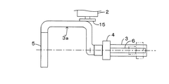
図7は、この発明に係るX線撮影装置の実施例2の要部の平面図であり、実施例1と異なるところは次の通りである。
支持アーム3の回転軸心からX線検出器5の取り付け箇所までの部分が凹状に入りこんだ形状の凹状部3aに構成され、天板上の被検者に対するX線透視撮影を行うときに、天板および被検者を凹状部3a内に位置させることができるようになっている。他の構成は実施例1と同じであり、同一図番を付してその説明は省略する。
FIG. 7 is a plan view of the main part of the X-ray imaging apparatus according to the second embodiment of the present invention. The differences from the first embodiment are as follows.
The portion from the rotation axis of the
上記実施例では、アーム固定解除許容手段を、電気回路構成によって、接近検出用リミットスイッチ9の閉じ状態でアーム回転用ソレノイド21を励磁可能な状態にするように構成しているが、例えば、X線管4がX線検出器5に所定距離まで接近したことを赤外線センサや静電容量センサなどの非接触式センサにより検出して接近信号を出力するように構成し、その非接触式センサにコントローラを接続するとともに、コントローラにアーム回転用ソレノイド21を接続し、非接触式センサからの接近信号に応答してアーム回転用ソレノイド21を励磁可能な状態にするように構成するものでも良い。
In the above-described embodiment, the arm fixing release permission means is configured so that the
また、上記実施例では、X線管固定解除許容手段を、電気回路構成によって、水平検出用リミットスイッチ14の閉じ状態でX線管移動用ソレノイド13を励磁可能な状態にするように構成しているが、例えば、支持アーム3が水平姿勢にあることを赤外線センサや静電容量センサなどの非接触式センサにより検出して接近信号を出力するように構成し、その非接触式センサにコントローラを接続するとともに、コントローラにX線管移動用ソレノイド13を接続し、非接触式センサからの接近信号に応答してX線管移動用ソレノイド13を励磁可能な状態にするように構成するものでも良い。
Further, in the above embodiment, the X-ray tube fixing release permission means is configured so that the X-ray
1…支柱
2…キャリッジ
3…支持アーム
4…X線管
5…X線検出器
9…接近検出用リミットスイッチ(接近状態検出手段)
11…位置決めピン(X線管固定手段)
12…圧縮コイルスプリング(X線管固定手段)
13…X線管移動用ソレノイド(X線管固定解除許容手段)
14…水平検出用リミットスイッチ(水平検出手段)
18…切欠(アーム固定手段)
19…固定用ピン(アーム固定手段)
20…圧縮コイルスプリング(アーム固定手段)
21…アーム回転用ソレノイド(アーム固定解除許容手段)
DESCRIPTION OF SYMBOLS 1 ...
11 ... Positioning pin (X-ray tube fixing means)
12 ... Compression coil spring (X-ray tube fixing means)
13 ... Solenoid for moving X-ray tube (X-ray tube fixing release permitting means)
14 ... Limit switch for horizontal detection (horizontal detection means)
18 ... Notch (arm fixing means)
19: Pin for fixing (arm fixing means)
20: Compression coil spring (arm fixing means)
21. Solenoid for arm rotation (arm fixing release permission means)
Claims (2)
前記X線管のみを、そのX線照射方向に前記X線検出器に対して遠近変位可能に設け、前記支持アームを前記キャリッジに固定するアーム固定手段と、前記X線管が前記X線検出器に所定距離まで接近したことを検出する接近状態検出手段と、前記接近状態検出手段が所定距離までの接近を検出したことに応答して前記アーム固定手段の固定の解除を許容するアーム固定解除許容手段と、前記X線管が前記X線検出器に所定距離まで接近した状態で前記X線管を前記支持アームに固定するX線管固定手段と、前記支持アームが水平姿勢にあることを検出する水平検出手段と、前記水平検出手段が水平姿勢を検出したことに応答して前記X線管固定手段の固定の解除を許容するX線管固定解除許容手段とを備え、かつ、前記X線管が前記X線検出器に所定距離まで接近した状態で、前記支持アームの回転軸心を中心として前記X線管側と前記X線検出器側との重量がバランスするように構成してあることを特徴とするX線撮影装置。 An X-ray that irradiates the subject with X-rays on one end side in the longitudinal direction of the support arm is provided with a carriage that can be moved up and down on the support column, and a support arm that is rotatable about a horizontal axis. In the X-ray imaging apparatus provided with an X-ray detector for receiving X-rays irradiated from the X-ray tube and transmitted through the subject on the other end side while providing a tube,
Only the X-ray tube is provided to be displaceable in the X-ray irradiation direction with respect to the X-ray detector, and arm fixing means for fixing the support arm to the carriage, and the X-ray tube detects the X-ray. An approach state detecting means for detecting that the device has approached a predetermined distance, and an arm fixing release for permitting the unlocking of the arm fixing means in response to the approach state detecting means detecting an approach to the predetermined distance Permitting means , X-ray tube fixing means for fixing the X-ray tube to the support arm with the X-ray tube approaching the X-ray detector to a predetermined distance, and the support arm in a horizontal posture. Horizontal detection means for detecting, and X-ray tube fixing release permitting means for allowing the X-ray tube fixing means to be released in response to the horizontal detection means detecting a horizontal posture ; and X-ray inspection The X-ray tube side and the X-ray detector side are configured so that the weights of the X-ray tube side and the X-ray detector side are balanced around the rotation axis of the support arm in a state where the X-ray tube is close to a predetermined distance. X-ray equipment.
前記アーム固定解除許容手段が固定の解除を許容した状態で操作することにより、前記アーム固定手段の固定を解除する回転操作スイッチと、前記X線管固定解除許容手段が固定の解除を許容した状態で操作することにより、前記X線管固定手段の固定を解除するX線管移動操作スイッチとを備えているX線撮影装置。Rotation operation switch for releasing the fixation of the arm fixing means by operating in a state where the arm fixing release allowing means permits the release of the fixing, and the X-ray tube fixing release allowing means allowing the release of the fixation An X-ray imaging apparatus comprising: an X-ray tube moving operation switch for releasing the fixation of the X-ray tube fixing means by operating in step (1).
Priority Applications (1)
| Application Number | Priority Date | Filing Date | Title |
|---|---|---|---|
| JP2006246953A JP4802952B2 (en) | 2006-09-12 | 2006-09-12 | X-ray equipment |
Applications Claiming Priority (1)
| Application Number | Priority Date | Filing Date | Title |
|---|---|---|---|
| JP2006246953A JP4802952B2 (en) | 2006-09-12 | 2006-09-12 | X-ray equipment |
Publications (2)
| Publication Number | Publication Date |
|---|---|
| JP2008067770A JP2008067770A (en) | 2008-03-27 |
| JP4802952B2 true JP4802952B2 (en) | 2011-10-26 |
Family
ID=39289913
Family Applications (1)
| Application Number | Title | Priority Date | Filing Date |
|---|---|---|---|
| JP2006246953A Expired - Fee Related JP4802952B2 (en) | 2006-09-12 | 2006-09-12 | X-ray equipment |
Country Status (1)
| Country | Link |
|---|---|
| JP (1) | JP4802952B2 (en) |
Families Citing this family (4)
| Publication number | Priority date | Publication date | Assignee | Title |
|---|---|---|---|---|
| JP2010082319A (en) * | 2008-10-01 | 2010-04-15 | Toshiba Corp | X-ray apparatus and bed device |
| CN101856235A (en) * | 2010-06-30 | 2010-10-13 | 深圳市蓝韵实业有限公司 | Rotating arm of economical X-ray photography system |
| WO2014192111A1 (en) * | 2013-05-30 | 2014-12-04 | 株式会社島津製作所 | X-ray image capturing device |
| US9848842B2 (en) | 2014-09-26 | 2017-12-26 | Koninklijke Philips N.V. | Latching mechanism for X-ray tube assembly and X-ray imaging system |
Family Cites Families (12)
| Publication number | Priority date | Publication date | Assignee | Title |
|---|---|---|---|---|
| JPS6241642A (en) * | 1985-08-15 | 1987-02-23 | 株式会社 日立メデイコ | Top plate falling/erecting control circuit |
| JPH0725794Y2 (en) * | 1989-03-29 | 1995-06-07 | 株式会社島津製作所 | Quick-shooting equipment |
| SE9902181D0 (en) * | 1999-06-10 | 1999-06-10 | Siemens Elema Ab | Radiographic Equipment |
| JP2001057971A (en) * | 1999-08-23 | 2001-03-06 | Shimadzu Corp | X-ray fluoroscopic photographing table |
| US6851851B2 (en) * | 1999-10-06 | 2005-02-08 | Hologic, Inc. | Digital flat panel x-ray receptor positioning in diagnostic radiology |
| JP2002017712A (en) * | 2000-07-07 | 2002-01-22 | Shimadzu Corp | X-rays equipment |
| JP4678999B2 (en) * | 2001-07-27 | 2011-04-27 | 株式会社東芝 | X-ray diagnostic equipment |
| JP2003199743A (en) * | 2002-01-09 | 2003-07-15 | Shimadzu Corp | X-ray equipment |
| JP2004065807A (en) * | 2002-08-09 | 2004-03-04 | Hitachi Medical Corp | Roentgenography system |
| JP2004147946A (en) * | 2002-10-31 | 2004-05-27 | Shimadzu Corp | Roentgenography apparatus |
| WO2005065546A1 (en) * | 2004-01-06 | 2005-07-21 | Hitachi Medical Corporation | Radiographic apparatus |
| JP4635499B2 (en) * | 2004-07-21 | 2011-02-23 | 株式会社島津製作所 | Medical diagnostic equipment |
-
2006
- 2006-09-12 JP JP2006246953A patent/JP4802952B2/en not_active Expired - Fee Related
Also Published As
| Publication number | Publication date |
|---|---|
| JP2008067770A (en) | 2008-03-27 |
Similar Documents
| Publication | Publication Date | Title |
|---|---|---|
| JP4802952B2 (en) | X-ray equipment | |
| US9668708B2 (en) | X-ray imaging device | |
| WO2013049249A1 (en) | Digital radiography mechanical positioning system | |
| JP2014073321A (en) | Mobile x-ray imaging apparatus | |
| JP2019213583A (en) | Proximity operation x-ray fluoroscopic imaging apparatus | |
| JP6251725B2 (en) | Mobile X-ray device | |
| WO2019064670A1 (en) | Radiation photographing apparatus | |
| JP2015192853A (en) | Radiation generation apparatus | |
| JP2014195590A (en) | Radiation generating apparatus, radiographing apparatus, computer program and storage medium | |
| EP2609859B1 (en) | Radiological apparatus | |
| JP5511142B2 (en) | X-ray equipment | |
| WO2012070143A1 (en) | X-ray examination apparatus | |
| US10881361B2 (en) | Radiographic imaging apparatus | |
| EP1816963B1 (en) | Drive unit for x-ray system | |
| JP6107134B2 (en) | X-ray fluoroscope | |
| JP7110992B2 (en) | X-ray equipment | |
| JP6806271B2 (en) | X-ray equipment | |
| JP2008113702A (en) | Radiography equipment | |
| JP5316801B2 (en) | X-ray equipment | |
| JP2006075265A (en) | Manual holder for overhead travelling suspended x-ray tube | |
| CN114080185A (en) | CT imaging equipment | |
| CN111374685B (en) | X-ray photographic apparatus | |
| JP3199839U (en) | Standing radiation imaging table and standing radiation imaging apparatus | |
| JP4702036B2 (en) | X-ray diagnostic equipment | |
| JP6056626B2 (en) | X-ray fluoroscopic equipment |
Legal Events
| Date | Code | Title | Description |
|---|---|---|---|
| A621 | Written request for application examination |
Free format text: JAPANESE INTERMEDIATE CODE: A621 Effective date: 20081114 |
|
| A131 | Notification of reasons for refusal |
Free format text: JAPANESE INTERMEDIATE CODE: A131 Effective date: 20101214 |
|
| A977 | Report on retrieval |
Free format text: JAPANESE INTERMEDIATE CODE: A971007 Effective date: 20101216 |
|
| A521 | Request for written amendment filed |
Free format text: JAPANESE INTERMEDIATE CODE: A523 Effective date: 20110210 |
|
| TRDD | Decision of grant or rejection written | ||
| A01 | Written decision to grant a patent or to grant a registration (utility model) |
Free format text: JAPANESE INTERMEDIATE CODE: A01 Effective date: 20110712 |
|
| A01 | Written decision to grant a patent or to grant a registration (utility model) |
Free format text: JAPANESE INTERMEDIATE CODE: A01 |
|
| A61 | First payment of annual fees (during grant procedure) |
Free format text: JAPANESE INTERMEDIATE CODE: A61 Effective date: 20110725 |
|
| R151 | Written notification of patent or utility model registration |
Ref document number: 4802952 Country of ref document: JP Free format text: JAPANESE INTERMEDIATE CODE: R151 |
|
| FPAY | Renewal fee payment (event date is renewal date of database) |
Free format text: PAYMENT UNTIL: 20140819 Year of fee payment: 3 |
|
| LAPS | Cancellation because of no payment of annual fees |