JP4789773B2 - Game machine - Google Patents
Game machine Download PDFInfo
- Publication number
- JP4789773B2 JP4789773B2 JP2006285023A JP2006285023A JP4789773B2 JP 4789773 B2 JP4789773 B2 JP 4789773B2 JP 2006285023 A JP2006285023 A JP 2006285023A JP 2006285023 A JP2006285023 A JP 2006285023A JP 4789773 B2 JP4789773 B2 JP 4789773B2
- Authority
- JP
- Japan
- Prior art keywords
- display
- variable display
- effect
- command
- special
- Prior art date
- Legal status (The legal status is an assumption and is not a legal conclusion. Google has not performed a legal analysis and makes no representation as to the accuracy of the status listed.)
- Expired - Fee Related
Links
- 230000000694 effects Effects 0.000 claims description 1049
- 238000004519 manufacturing process Methods 0.000 claims description 121
- 230000005540 biological transmission Effects 0.000 claims description 35
- 238000013500 data storage Methods 0.000 claims description 33
- 238000009795 derivation Methods 0.000 claims description 3
- 238000000034 method Methods 0.000 description 428
- 230000008569 process Effects 0.000 description 421
- 239000000872 buffer Substances 0.000 description 198
- 238000011161 development Methods 0.000 description 133
- 230000018109 developmental process Effects 0.000 description 133
- 230000015654 memory Effects 0.000 description 82
- 238000012545 processing Methods 0.000 description 67
- 238000013461 design Methods 0.000 description 45
- 230000004044 response Effects 0.000 description 41
- 230000009467 reduction Effects 0.000 description 33
- 238000003860 storage Methods 0.000 description 30
- 230000008859 change Effects 0.000 description 22
- 230000001276 controlling effect Effects 0.000 description 22
- 238000005034 decoration Methods 0.000 description 20
- 238000001514 detection method Methods 0.000 description 16
- 238000010586 diagram Methods 0.000 description 16
- 230000006870 function Effects 0.000 description 9
- 230000009471 action Effects 0.000 description 8
- 238000004904 shortening Methods 0.000 description 8
- 238000004891 communication Methods 0.000 description 5
- 239000000284 extract Substances 0.000 description 5
- 238000006243 chemical reaction Methods 0.000 description 4
- 239000000758 substrate Substances 0.000 description 4
- 102100024233 High affinity cAMP-specific 3',5'-cyclic phosphodiesterase 7A Human genes 0.000 description 3
- 101001117267 Homo sapiens High affinity cAMP-specific 3',5'-cyclic phosphodiesterase 7A Proteins 0.000 description 3
- 230000005856 abnormality Effects 0.000 description 3
- 238000003825 pressing Methods 0.000 description 3
- 230000001105 regulatory effect Effects 0.000 description 3
- 238000009877 rendering Methods 0.000 description 3
- 241001465754 Metazoa Species 0.000 description 2
- 238000004458 analytical method Methods 0.000 description 2
- 230000002457 bidirectional effect Effects 0.000 description 2
- 238000004040 coloring Methods 0.000 description 2
- 238000003745 diagnosis Methods 0.000 description 2
- 238000007726 management method Methods 0.000 description 2
- 239000011159 matrix material Substances 0.000 description 2
- 238000012805 post-processing Methods 0.000 description 2
- 230000005236 sound signal Effects 0.000 description 2
- 241000722921 Tulipa gesneriana Species 0.000 description 1
- OMFRMAHOUUJSGP-IRHGGOMRSA-N bifenthrin Chemical compound C1=CC=C(C=2C=CC=CC=2)C(C)=C1COC(=O)[C@@H]1[C@H](\C=C(/Cl)C(F)(F)F)C1(C)C OMFRMAHOUUJSGP-IRHGGOMRSA-N 0.000 description 1
- 230000033228 biological regulation Effects 0.000 description 1
- 230000004397 blinking Effects 0.000 description 1
- 238000004364 calculation method Methods 0.000 description 1
- 239000003086 colorant Substances 0.000 description 1
- 230000006835 compression Effects 0.000 description 1
- 238000007906 compression Methods 0.000 description 1
- 238000005336 cracking Methods 0.000 description 1
- 238000012938 design process Methods 0.000 description 1
- 238000009434 installation Methods 0.000 description 1
- 238000012538 light obscuration Methods 0.000 description 1
- 239000004973 liquid crystal related substance Substances 0.000 description 1
- 238000012986 modification Methods 0.000 description 1
- 230000004048 modification Effects 0.000 description 1
- 238000012544 monitoring process Methods 0.000 description 1
- 238000013139 quantization Methods 0.000 description 1
- 239000004065 semiconductor Substances 0.000 description 1
- 230000001550 time effect Effects 0.000 description 1
- 230000007704 transition Effects 0.000 description 1
Images


Landscapes
- Pinball Game Machines (AREA)
- Display Devices Of Pinball Game Machines (AREA)
Description
本発明は、パチンコ遊技機等の遊技機に係り、詳しくは、各々が識別可能な複数種類の識別情報の可変表示を行う可変表示手段を備え、識別情報の可変表示結果が予め定められた特定表示結果となったことに基づいて、遊技者にとって有利な特定遊技状態に制御する遊技機に関する。 The present invention relates to a gaming machine such as a pachinko gaming machine, and more specifically, includes a variable display means for variably displaying a plurality of types of identification information that can be individually identified, and the identification information variable display result is predetermined. The present invention relates to a gaming machine that controls a specific gaming state advantageous to a player based on the display result.
パチンコ遊技機等の遊技機においては、液晶表示装置(以下LCD:Liquid Crystal Display)等の表示装置上に所定の識別情報(以下、表示図柄)を更新表示やスクロール表示させることで変動可能とする可変表示を行い、その表示結果により所定の遊技価値を付与するか否かを決定する、いわゆる可変表示ゲームによって遊技興趣を高めたものが数多く提供されている。 In a gaming machine such as a pachinko machine, it can be changed by displaying predetermined identification information (hereinafter referred to as a display symbol) on a display device such as a liquid crystal display (hereinafter referred to as “LCD”) by updating or scrolling. There are a number of games that have been enhanced by a so-called variable display game that performs variable display and determines whether or not to give a predetermined game value based on the display result.
可変表示ゲームには、前述の表示装置を画像表示装置として用いることにより行うものがある。こうした可変表示ゲームでは、始動入賞口を通過する遊技球の検出(可変表示の始動条件が成立したこと)に基づいて表示図柄の変動を開始させ、表示図柄の変動が完全に停止した際の停止図柄(確定図柄)の態様が特定表示態様となっている場合を「大当り」とするゲームである。可変表示ゲームにおいて「大当り」となると、大入賞口またはアタッカと呼ばれる特別電動役物を開放状態とし、遊技者に対して遊技球の入賞が極めて容易となる状態を一定時間継続的に提供する。この状態を「特定遊技状態」という。 Some variable display games are played by using the above display device as an image display device. In such a variable display game, the change of the display symbol is started based on the detection of the game ball passing through the start winning opening (the start condition of the variable display is satisfied), and the stop when the change of the display symbol is completely stopped. A game in which a case of a symbol (determined symbol) is a specific display mode is a “big hit”. In the variable display game, when a “hit” is made, a special electric combination called a big prize opening or an attacker is opened, and a state in which a game ball can be won extremely easily is provided to a player for a certain period of time. This state is referred to as a “specific game state”.
このような遊技機としては、例えばリーチ状態の成立時に、複数のリーチアクションを順次に紹介して、最後に紹介したリーチアクションが実行されるものが提案されている(例えば特許文献1参照)。
特許文献1に記載された技術では、複数のリーチアクションを紹介するために、各リーチアクションに対応する静止画像が表示されるだけである。そのため、リーチアクションなどの演出表示を紹介することによる演出効果を十分に高めることができなかった。
In the technique described in
この発明は、上記実状に鑑みてなされたものであり、演出表示を紹介することによる演出効果を向上させることができる遊技機を提供することを目的とする。 This invention is made in view of the said actual condition, and it aims at providing the gaming machine which can improve the production effect by introducing production display.
上記目的を達成するため、本願の請求項1に記載の遊技機は、各々が識別可能な複数種類の識別情報(例えば飾り図柄など)の可変表示を行う可変表示手段(例えば画像表示装置5など)を備え、前記識別情報の可変表示結果が予め定められた特定表示結果(例えば大当り組合せの確定飾り図柄など)となったことに基づいて、遊技者にとって有利な特定遊技状態(例えば大当り遊技状態など)に制御する遊技機(例えばパチンコ遊技機1など)であって、遊技の進行を制御する遊技制御手段(例えば遊技制御用マイクロコンピュータ100のCPU111など)と、前記識別情報の可変表示パターン及び可変表示時間を示す可変表示コマンドに基づいて、前記可変表示手段の表示制御を行う演出制御手段(例えば演出制御用マイクロコンピュータ120のCPU131や表示制御用マイクロコンピュータ140のCPU151やVDP141など)とを備え、前記遊技制御手段は、前記識別情報の可変表示結果が前記特定表示結果のうち予め定められた特別表示結果(例えば確変大当り組合せの確定飾り図柄)となったことに基づいて、前記特定遊技状態が終了した後に前記特定表示結果となる確率が前記特定遊技状態とは異なる通常遊技状態時よりも高い高確率状態に制御する遊技状態制御手段(例えば大当り種別判定バッファ値が「01H」であるときにCPU111がステップS293の処理を実行して確変フラグをオン状態に設定した後に、ステップS504の処理を実行する部分など)と、前記特定遊技状態とするか否かと、前記高確率状態とするか否かと、を可変表示結果の導出表示以前に決定する事前決定手段(例えばCPU111がステップS504、S508の処理を実行する部分など)と、前記事前決定手段による決定結果を示す表示結果コマンドを送信する表示結果コマンド送信手段(例えばCPU111がステップS510、S511の処理のいずれかを実行した後にステップS232にて設定した可変表示開始用コマンドテーブル230に格納された表示結果通知コマンド用設定データをステップS132、S139にて読み出し、ステップS133、S142の処理を実行する部分など)と、前記事前決定手段の決定に基づいて、前記可変表示コマンドを決定する可変表示コマンド決定手段(例えばCPU111がステップS221〜S231の処理を実行する部分など)と、前記可変表示コマンド決定手段により決定された前記可変表示コマンドを送信する可変表示コマンド送信手段(例えばCPU111がステップS232にて設定した可変表示開始用コマンドテーブル230に格納された可変表示開始コマンド用設定データをステップS132、S139にて読み出し、ステップS133、S142の処理を実行する部分など)とを含み、前記可変表示コマンド決定手段は、前記可変表示コマンドとして、前記特別表示結果を表示させる特別可変表示パターンを特定可能な特別可変表示コマンド、前記特定表示結果であるが前記特別表示結果ではない非特別表示結果を表示させる非特別可変表示パターンを特定可能な非特別可変表示コマンド、前記特別表示結果または前記非特別表示結果を表示させる共通の特定可変表示パターンを特定可能な特定可変表示コマンド、前記特定遊技状態に制御しないことを示す非特定表示結果を表示させる非特定可変表示パターンを特定可能な非特定可変表示コマンドのいずれかに決定し、前記演出制御手段は、前記可変表示コマンドあるいは前記表示結果コマンドに基づいて、前記可変表示手段による可変表示の表示結果として導出表示される識別情報を決定する識別情報決定手段(例えばCPU131がステップS321〜S328の処理を実行する部分など)と、複数種類の演出画像に対応した複数種類の画像データを記憶する画像データ記憶手段(例えば画像データメモリ142など)と、前記識別情報の可変表示が所定の表示態様(例えばリーチなど)となった後に、演出態様が異なる複数種類の演出表示(例えば図10(B)及び(C)に示す第1リーチにおけるリーチ演出表示、図11(B)及び(C)に示す第2リーチにおけるリーチ演出表示、図12(B)及び(C)に示す第3リーチにおけるリーチ演出表示など)のいずれかを前記可変表示手段にて実行してから前記識別情報の可変表示結果を導出表示させる演出表示実行手段(例えば遊技制御用マイクロコンピュータ100のCPU111がステップS222、S225の処理のいずれかを実行した後にステップS230の処理にて発展A−1〜発展A−3、発展B−1〜発展B−3、発展C−1〜発展C−3の可変表示パターンのいずれかに決定したことに基づき、演出制御用マイクロコンピュータ120のCPU131がステップS356の処理を実行する部分など)とを含み、前記画像データ記憶手段が記憶する画像データは、複数種類の動画像に対応した圧縮データからなる複数種類の動画像データ(例えば動画像M101〜M103、M201〜M203、MA01〜MA03を表示するためのリーチ紹介用動画像データやリーチ演出用動画像データなど)を含み、前記演出表示実行手段は、前記複数種類の演出表示のうちでいずれを実行するかを決定する演出表示決定手段(例えば遊技制御用マイクロコンピュータ100のCPU111がステップS222、S225の処理のいずれかを実行した後にステップS230の処理を実行する部分など)と、前記識別情報の可変表示が所定の表示態様となったことに対応して、前記画像データ記憶手段から読み出した圧縮データとしての動画像データのデコードを行い、前記複数種類の演出表示を紹介する動画像を前記可変表示手段に表示してから、前記演出表示決定手段により決定された演出表示を前記可変表示手段にて実行する紹介動画像表示手段(例えば演出制御用マイクロコンピュータ120のCPU131が発展A−1〜発展A−3、発展B−1〜発展B−3、発展C−1〜発展C−3の可変表示パターンのいずれかに対応してステップS332にて決定した演出制御パターンの設定に基づき、ステップS356にて表示制御指令を送り、この表示制御指令に応じて表示制御用マイクロコンピュータ140のCPU151やVDP141により動画像データ記憶部352から読み出されたリーチ紹介用動画像データに基づく図47(A)〜(J)に示すような演出表示が画像表示装置5にて実行される部分など)とを含み、前記識別情報決定手段は、前記非特定可変表示コマンド、前記特別可変表示コマンドまたは前記非特別可変表示コマンドを受信したときは、前記表示結果コマンドを受信したか否かにかかわらず、受信した可変表示コマンドに対応した表示結果となる識別情報を決定する対応識別情報決定手段と、前記特定可変表示コマンドを受信したときに、前記表示結果コマンドを受信したか否かを判定する表示結果コマンド受信判定手段と、前記表示結果コマンド受信判定手段により受信したと判定されたことに基づいて、受信した表示結果コマンドに対応した表示結果となる識別情報を決定する受信時識別情報決定手段と、前記表示結果コマンド受信判定手段により受信していないと判定されたことに基づいて、前記非特別表示結果となる識別情報を決定する特定識別情報決定手段とを含む。
In order to achieve the above object, the gaming machine according to
請求項2に記載の遊技機において、前記紹介動画像表示手段は、前記複数種類の演出表示のうち第1演出表示を紹介する第1動画像の表示を開始した後に、当該第1動画像の表示が終了してから前記第1演出表示とは異なる第2演出表示を紹介する第2動画像の表示を開始することにより、前記複数種類の演出表示を順次に紹介する(例えば図46に示すように各表示領域A01〜A03にて順次に動画像を表示させる部分など)。
3. The gaming machine according to
請求項3に記載の遊技機において、前記画像データ記憶手段は、前記演出表示が実行される前の前記動画像データとして、前記演出表示が開始されるときの表示内容と連続性を有する動画像データ(例えば演出表示と同一の画像や類似の画像を生成するための動画像データなど)を記憶する。
4. The gaming machine according to
請求項4に記載の遊技機において、前記紹介動画像表示手段は、前記複数種類の演出表示を所定順序で紹介するように動画像の表示を行う所定順序表示手段(例えばCPU131が発展A−1〜発展A−3の可変表示パターンのいずれかに対応してステップS332にて決定した演出制御パターンの設定に基づき、第1リーチ→第2リーチ→第3リーチの順序で紹介する動画像の表示を行う部分など)を含み、前記演出表示決定手段は、前記所定順序表示手段により先に紹介される演出表示を実行したときよりも前記所定順序表示手段により後に紹介される演出表示を実行したときの方が前記特定表示結果となる確率が高くなるように設定された決定用データを用いて、演出表示の決定を行う(例えばCPU111がステップS230にてリーチハズレパターン決定テーブル220Cや大当りパターン決定テーブル220Dを参照して可変表示パターンを決定することにより、図14に示す選択確率や大当り信頼度で発展A−1〜発展A−3の可変表示パターンのいずれかに決定する部分など)。
5. The gaming machine according to
請求項5に記載の遊技機において、前記紹介動画像表示手段は、前記所定順序とは異なる特殊順序で前記複数種類の演出表示を紹介するように動画像の表示を行う特殊順序表示手段(例えばCPU131が発展B−1〜発展B−3の可変表示パターンのいずれかに対応してステップS332にて決定した演出制御パターンの設定に基づき、第2リーチ→第1リーチ→第3リーチの順序で紹介する動画像の表示を行う部分など)と、前記所定順序表示手段により前記所定順序で紹介されたときよりも前記特殊順序表示手段により前記特殊順序で紹介されたときの方が前記特定表示結果となる確率が高くなるように設定された決定用データを用いて、前記所定順序表示手段と前記特殊順序表示手段のいずれにより動画像の表示を行うかを決定する順序表示決定手段(例えばCPU111がステップS230にてリーチハズレパターン決定テーブル220Cや大当りパターン決定テーブル220Dを参照して可変表示パターンを決定することにより、図14に示す選択確率や大当り信頼度で発展A−1〜発展A−3あるいは発展B−1〜発展B−3の可変表示パターンのいずれかに決定する部分など)とを含む。
6. The gaming machine according to
請求項6に記載の遊技機において、前記演出表示決定手段は、前記紹介動画像表示手段により紹介された演出表示を実行したときよりも前記紹介動画像表示手段により紹介された演出表示とは異なる演出表示を実行したときの方が前記特定表示結果となる確率が高くなるように設定された決定用データを用いて、演出表示の決定を行う(例えばCPU111がステップS230にてリーチハズレパターン決定テーブル220Cや大当りパターン決定テーブル220Dを参照して可変表示パターンを決定することにより、図14に示す選択確率や大当り信頼度で発展C−1〜発展C−3の可変表示パターンのいずれかに決定する部分など)。
7. The gaming machine according to
請求項7に記載の遊技機においては、遊技機における演出状態を複数種類の演出状態のいずれかに制御する演出状態制御手段(例えばCPU131がステップS306の演出モード設定処理にて設定した演出モード特定フラグの値に対応する演出制御パターンテーブルを、ステップS331にて演出制御パターンテーブル300A〜300Cのうちから選択する部分など)を備え、前記紹介動画像表示手段は、前記演出状態制御手段により制御されている前記演出状態に応じて前記画像データ記憶手段から異なる動画像データを読み出して前記複数種類の演出表示を紹介する動画像を表示する(例えばCPU131がステップS332にて決定した演出制御パターンの設定に基づき、ステップS356にて表示制御指令を送り、この表示制御指令に応じて表示制御用マイクロコンピュータ140のCPU151やVDP141により動画像データ記憶部352から読み出された動画像M101〜M103、M201〜M203を表示するためのリーチ紹介用動画像データなどに基づく演出表示が画像表示装置5にて実行される部分など)。
In the gaming machine according to
本発明は、以下に示す効果を有する。 The present invention has the following effects.
請求項1に記載の遊技機によれば、演出表示実行手段は、識別情報の可変表示が所定の表示態様となったことに対応して、画像データ記憶手段から読み出した圧縮データとしての動画像データのデコードを行い、複数種類の演出表示を紹介する動画像を可変表示手段に表示してから、演出表示決定手段により決定された演出表示を可変表示手段にて実行する紹介動画像表示手段を含むように構成されている。
これにより、複数種類の演出表示を動画像により紹介した後に演出表示を実行することができ、演出表示を紹介することによる演出効果を向上させることができる。
また、非特定可変表示コマンド、特別可変表示コマンドまたは非特別可変表示コマンドを受信したときは、対応識別情報決定手段により受信した可変表示コマンドに対応した表示結果となる識別情報を決定する。その一方で、特定可変表示コマンドを受信したときには、表示結果コマンド受信判定手段により表示結果コマンドを受信していないと判定されたことに基づいて、特定識別情報決定手段により非特別表示結果となる識別情報を決定する。
これにより、演出制御手段にて非特定可変表示コマンド、特別可変表示コマンドまたは非特別可変表示コマンドを受信した場合には、対応する可変表示結果を導出表示することができ、特定可変表示コマンドを受信した場合に表示結果コマンドを受信できなくても、非特別表示結果を導出表示することができるので、より正常に近い表示を行うことができる。
According to the gaming machine of the first aspect, the effect display executing means is a moving image as compressed data read from the image data storage means in response to the variable display of the identification information being in a predetermined display mode. An introductory moving image display means that decodes data and displays a moving image that introduces a plurality of types of effect display on the variable display means, and then executes the effect display determined by the effect display determination means on the variable display means. It is configured to include.
As a result, the effect display can be executed after introducing a plurality of types of effect display using moving images, and the effect of introducing the effect display can be improved.
When a non-specific variable display command, a special variable display command, or a non-special variable display command is received, identification information that is a display result corresponding to the variable display command received by the corresponding identification information determination unit is determined. On the other hand, when the specific variable display command is received, the specific identification information determination unit identifies the non-special display result based on the determination that the display result command reception determination unit has not received the display result command. Determine information.
As a result, when the non-specific variable display command, special variable display command or non-special variable display command is received by the production control means, the corresponding variable display result can be derived and displayed, and the specific variable display command is received. In this case, even if the display result command cannot be received, the non-special display result can be derived and displayed, so that a more normal display can be performed.
請求項2に記載の遊技機においては、複数種類の演出表示のうち第1演出表示を紹介する第1動画像の表示を開始した後に、当該第1動画像の表示が終了してから第1演出表示とは異なる第2演出表示を紹介する第2動画像の表示を開始する。
これにより、複数の動画像を同時に表示することによる処理負担の増大を防止することができる。
In the gaming machine according to
As a result, it is possible to prevent an increase in processing load due to simultaneous display of a plurality of moving images.
請求項3に記載の遊技機においては、演出表示が実行される前の動画像データとして、演出表示が開始されるときの表示内容と連続性を有する動画像データが画像データ記憶手段に記憶されている。
これにより、動画像を表示する期間から、演出表示を実行する期間となったときに、表示画像をスムーズに切り替えることができ、遊技者に違和感を与えないようにすることができる。
In the gaming machine according to
Thereby, when it becomes the period which performs an effect display from the period which displays a moving image, a display image can be switched smoothly and it can prevent a player from feeling uncomfortable.
請求項4に記載の遊技機においては、所定順序表示手段により複数種類の演出表示が所定順序で紹介され、先に紹介される演出表示を実行したときよりも後に紹介される演出表示を実行したときの方が特定表示結果となる確率が高くなる。
これにより、特定表示結果となる確率を遊技者が容易に認識することができ、特定表示結果となることに対する遊技者の期待感を高めて、遊技の興趣を向上させることができる。
In the gaming machine according to
Thereby, the player can easily recognize the probability of the specific display result, the player's expectation for the specific display result can be enhanced, and the interest of the game can be improved.
請求項5に記載の遊技機においては、特殊順序表示手段により複数種類の演出表示が所定順序とは異なる特殊順序で紹介され、所定順序で紹介されたときよりも特殊順序で紹介されたときの方が特定表示結果となる確率が高くなる。
これにより、意外性のある演出によって特定表示結果となることに対する遊技者の期待感を高めて、遊技の興趣を向上させることができる。
In the gaming machine according to
Thereby, the player's expectation that a specific display result is obtained by an unexpected performance can be enhanced, and the interest of the game can be improved.
請求項6に記載の遊技機においては、紹介された演出表示を実行したときよりも紹介された演出表示とは異なる演出表示を実行したときの方が特定表示結果となる確率が高くなる。
これにより、意外性のある演出によって特定表示結果となることに対する遊技者の期待感を高めて、遊技の興趣を向上させることができる。
In the gaming machine according to the sixth aspect , the probability that the specific display result is higher when an effect display different from the introduced effect display is executed than when the introduced effect display is executed.
Thereby, the player's expectation that a specific display result is obtained by an unexpected performance can be enhanced, and the interest of the game can be improved.
請求項7に記載の遊技機においては、演出状態に応じて異なる動画像データが読み出されて複数種類の演出表示を紹介する動画像が表示される。
これにより、演出状態に応じて多様な動画像を表示して演出効果を高め、遊技の興趣を向上させることができる。
In the gaming machine according to the seventh aspect , different moving image data is read according to the effect state, and a moving image introducing a plurality of types of effect display is displayed.
Thereby, various moving images can be displayed according to the production state, the production effect can be enhanced, and the interest of the game can be improved.
以下、図面を参照しつつ、本発明の一実施形態を詳細に説明する。図1は、本実施例におけるパチンコ遊技機1の正面図であり、主要部材の配置レイアウトを示す。パチンコ遊技機(遊技機)1は、大別して、遊技盤面を構成する遊技盤(ゲージ盤)2と、遊技盤2を支持固定する遊技機用枠(台枠)3とから構成されている。遊技盤2にはガイドレールによって囲まれた、ほぼ円形状の遊技領域が形成されている。この遊技領域内の所定位置には、各々が識別可能な複数種類の特別図柄を変動可能に表示(可変表示)する特別図柄表示装置4が設けられている。なお、特別図柄表示装置4の設置位置は、遊技領域内の所定位置に限定されず、遊技領域外の所定位置であってもよい。
Hereinafter, an embodiment of the present invention will be described in detail with reference to the drawings. FIG. 1 is a front view of a
図1に示すパチンコ遊技機1における遊技領域の中央位置には、例えば特別図柄とは異なる各々が識別可能な複数種類の識別情報としての飾り図柄(「演出図柄」ともいう)を可変表示することや、飾り図柄とは異なる演出用の画像を表示することといった、複数種類の画像を表示することにより演出動作を行うために用いられる画像表示装置5が設けられている。画像表示装置5の下方には、始動入賞口を形成する普通可変入賞球装置6が配置されている。普通可変入賞球装置6の下方には、大入賞口を形成する特別可変入賞球装置7や、普通図柄表示装置20が設けられている。
In the
特別図柄表示装置4は、例えば7セグメントやドットマトリクスのLED等から構成されている。特別図柄表示装置4は、可変表示ゲームとしての特図ゲームにおいて、例えば「00」〜「99」を示す数字や「−−」を示す記号等から構成される複数種類の特別図柄を可変表示する。この特図ゲームは、例えば普通可変入賞球装置6が形成する始動入賞口に遊技球が入賞することといった、特別図柄を可変表示するための実行条件が成立した後に、例えば前回の特図ゲームが終了したことや大当り遊技状態が終了したことといった、特別図柄を可変表示するための開始条件が成立したことに基づいて開始される。この実施の形態では、一例として、特別図柄表示装置4が「左」及び「右」の特別図柄可変表示部を備え、各特別図柄可変表示部において、「0」〜「9」を示す数値や「−」を示す記号等から構成される特別図柄の可変表示を行うものとする。各特別図柄可変表示部において可変表示される複数種類の特別図柄には、それぞれに対応した図柄番号が付されている。例えば、「0」〜「9」を示す数値のそれぞれに対して、「0」〜「9」の図柄番号が付され、「−」を示す記号に対して、「10」の図柄番号が付されている。
The special
画像表示装置5は、例えばLCD等から構成され、多数の画素(ピクセル)を用いたドットマトリクス方式による画面表示を行うものであればよい。画像表示装置5の表示画面では、特別図柄表示装置4による特図ゲームにおける特別図柄の可変表示に対応して、例えば3つに分割された表示領域としての可変表示部にて、各々が識別可能な複数種類の飾り図柄を可変表示する。この飾り図柄の可変表示も、開始条件が成立したことに基づいて行われる可変表示ゲームである。
The
例えば、画像表示装置5には、「左」、「中」、「右」の可変表示部が配置され、特別図柄表示装置4により特図ゲームが実行されることに対応して、各可変表示部にて飾り図柄が可変表示される。すなわち、特別図柄表示装置4における特別図柄の可変表示が開始されるときには、画像表示装置5における「左」、「中」、「右」の各可変表示部にて飾り図柄の可変表示(例えば切替表示やスクロール表示)を開始させ、その後、特別図柄表示装置4による特図ゲームにおける可変表示結果として確定特別図柄が停止表示されるときに、画像表示装置5における「左」、「中」、「右」の各可変表示部にて飾り図柄の可変表示結果となる確定飾り図柄が停止表示(導出表示)される。また、「左」、「中」、「右」の各可変表示部は、画像表示装置5の表示領域内で移動可能とされ、飾り図柄を縮小あるいは拡大して表示することができるようにしてもよい。
For example, the
画像表示装置5における「左」、「中」、「右」の各可変表示部では、例えば8種類の図柄(英数字「1」〜「8」あるいは漢数字「一」〜「八」、英文字「A」〜「H」、所定のモチーフに関連する8個のキャラクタ画像、数字や文字あるいは記号とキャラクタ画像との組合せなど。なお、キャラクタ画像は、例えば人物や動物、これら以外の物体、もしくは、文字などの記号、あるいは、その他の任意の図形を示す演出画像であればよい)が、飾り図柄として変動可能に表示される。飾り図柄のそれぞれには、対応する図柄番号が付されている。例えば、「1」〜「8」を示す英数字のそれぞれに対して、「1」〜「8」の図柄番号が付されていればよい。
In each of the “left”, “middle”, and “right” variable display portions in the
画像表示装置5において飾り図柄の可変表示が開始されると、「左」、「中」、「右」の各可変表示部では、例えば図柄番号が小さいものから大きいものへと切替表示やスクロール表示が行われ、図柄番号が最大の「8」である飾り図柄が表示されると、次に図柄番号が最小の「1」である飾り図柄が表示される。あるいは、図柄番号が大きいものから小さいものへと切替表示やスクロール表示を行って、図柄番号が最小の「1」である飾り図柄が表示されると、次に図柄番号が最大の「8」である飾り図柄が表示されてもよい。
When variable display of decorative symbols is started in the
また、画像表示装置5には、普通可変入賞球装置6が形成する始動入賞口に入賞した有効入賞球数としての保留記憶数(特図保留記憶数)を表示する特別図柄始動記憶表示エリアが設けられていてもよい。特別図柄始動記憶表示エリアでは、特図保留記憶数が所定の上限値(例えば「4」)未満のときの有効始動入賞に対応して、入賞表示が行われる。具体的な一例として、特図保留記憶数が1加算されたときには、通常青色あるいは非表示であった表示部位のうちの1つ(例えば青色あるいは非表示となっている表示部位のうち左端あるいは下端の表示部位)を赤色表示あるいは可視表示に変化させる。これに対して、特図保留記憶数が1減算されたときには、赤色表示あるいは可視表示されている表示部位のうちの1つ(例えば赤色あるいは可視表示となっている表示部位のうち右端あるいは上端の表示部位)を青色表示あるいは非表示に戻す。あるいは、特別図柄始動記憶表示エリアでは、特図保留記憶数を示す数字を表示することなどにより、特図保留記憶数を遊技者等が認識できるようにしてもよい。特別図柄始動記憶表示エリアとともに、あるいは特別図柄始動記憶表示エリアに代えて、特図保留記憶数を表示する表示器(特別図柄始動記憶表示器)を設けるようにしてもよい。
In addition, the
普通図柄表示装置20は、例えば発光ダイオード(LED)等を備えて構成され、遊技領域に設けられた通過ゲート41を通過した遊技球がゲートスイッチ21(図2)によって検出されたことを実行条件とする普通図ゲームにおいて、点灯、点滅、発色などが制御される。
The normal
普通可変入賞球装置6は、ソレノイド81(図2)によって垂直(通常開放)位置と傾動(拡大開放)位置との間で可動制御される一対の可動翼片を有する電動チューリップ型役物(普通電動役物)を備え、始動入賞口を形成する。普通可変入賞球装置6に形成された始動入賞口へと進入した遊技球は、始動口スイッチ22(図2)によって検出され、その検出に基づき特別図柄や飾り図柄の可変表示を実行するための実行条件(始動条件)が成立する。始動口スイッチ22によって遊技球が検出されたことに基づいて、所定個数(例えば4個)の賞球の払い出しが行われる。
The normal variable winning
特別可変入賞球装置7は、ソレノイド82(図2)によって入賞領域となる大入賞口を開放及び閉鎖制御する開閉板を備えて構成される。特別可変入賞球装置7にて開閉板により開放された大入賞口内へと遊技球が進入した場合には、カウントスイッチ23(図2)によって当該遊技球が検出されたことに基づいて、所定個数(例えば「15」)の賞球の払出が行われる。
The special variable winning
遊技盤2の表面には、上記の構成以外にも、ランプを内蔵した風車、アウト口等が設けられている。遊技機用枠3の左右上部位置には、効果音等を再生出力するためのスピーカ8L、8Rが設けられており、さらに遊技領域周辺部には、遊技効果ランプ9が設けられている。パチンコ遊技機1の遊技領域における各構造物(例えば普通可変入賞球装置6、特別可変入賞球装置7等)の周囲には装飾用LEDが設置されていてもよい。遊技機用枠3の右下部位置には、遊技球を発射するために遊技者等によって操作される打球操作ハンドル(操作ノブ)30が設けられている。遊技機用枠3の左下部位置には、パチンコ遊技機1における演出動作の態様(演出モード)を変更するためなどに遊技者等によって操作される操作スイッチ50が設けられている。
In addition to the above configuration, the surface of the
普通図柄表示装置20による普通図ゲームでは、普通図柄の可変表示を開始させた後、所定の当りパターンで表示が行われると、表示結果が「当り」となり(普通当り)、普通可変入賞球装置6を構成する電動チューリップの可動翼片が傾動位置に制御(拡大開放制御)され、所定時間が経過すると垂直位置に制御(通常開放制御)される。
In the normal symbol game by the normal
特別図柄表示装置4による特図ゲームでは、特別図柄の可変表示を開始させた後、所定時間が経過すると、特別図柄の可変表示結果となる確定特別図柄を停止表示(導出表示)する。このとき、確定特別図柄として特定の特別図柄(大当り図柄)が停止表示されれば特定表示結果としての「大当り」となり、大当り図柄以外の特別図柄が停止表示されれば「ハズレ」となる。
In the special symbol game by the special
特図ゲームでの可変表示結果が「大当り」になると、特定遊技状態としての大当り遊技状態に制御される。この実施の形態におけるパチンコ遊技機1では、具体的な一例として、「33」あるいは「77」を示す特別図柄を大当り図柄とし、「−−」を示す特別図柄をハズレ図柄としている。
When the variable display result in the special figure game is “big hit”, it is controlled to the big hit gaming state as the specific gaming state. In the
特別図柄表示装置4による特図ゲームでの確定特別図柄が大当り図柄「33」あるいは「77」となる場合には、画像表示装置5における飾り図柄の可変表示結果として、例えば「左」、「中」、「右」の各可変表示部にて所定の大当り組合せを構成する確定飾り図柄が停止表示される。大当り組合せの確定飾り図柄は、例えば「左」、「中」、「右」の各可変表示部において予め定められた有効ライン上に、同一の飾り図柄が揃って停止表示されるものであればよい。一例として、有効ラインは、「左」、「中」、「右」の各可変表示部における上段のみ、中段のみ、下段のみからなる水平方向や、「左」の可変表示部における上段と「中」の可変表示部における中段と「右」の可変表示部における下段とからなる斜め方向、あるいは、「左」の可変表示部における下段と「中」の可変表示部における中段と「右」の可変表示部における上段とからなる斜め方向などに、予め定められていればよい。このような大当り組合せの確定飾り図柄は、大当り遊技状態に制御されることに対応した特定表示結果に含まれる。
When the confirmed special symbol in the special symbol game by the special
特別図柄表示装置4による特図ゲームで大当り図柄「33」あるいは「77」が停止表示されたことや、画像表示装置5における飾り図柄の可変表示結果として大当り組合せの確定飾り図柄が停止表示されたことに対応して制御される大当り遊技状態においては、特別可変入賞球装置7の開閉板が、所定期間(例えば29秒間)あるいは所定個数(例えば10個)の入賞球が発生するまでの期間にて、大入賞口を開放状態とすることにより、遊技者にとって有利な第1状態とする。このように大入賞口を開放状態とした開閉板は、遊技盤2の表面を落下する遊技球を受け止め、その後に大入賞口を閉鎖状態とすることにより、遊技者にとって不利な第2状態とする。こうして大入賞口を第1状態となる開放状態としてから第2状態となる閉鎖状態とすることで、1回のラウンドが終了する。この実施の形態では、特図ゲームで大当り図柄「33」あるいは「77」が停止表示されたことや、画像表示装置5における飾り図柄の可変表示結果として大当り組合せの確定飾り図柄が停止表示されたことに対応する特定遊技状態としての大当り遊技状態において、大入賞口の開閉サイクルとしてのラウンドを、所定回数(例えば「15」)に達するまで繰り返すことができる。
In the special symbol game by the special
なお、特別可変入賞球装置7の開閉板は、例えばパチンコ遊技機1の電源投入後に大当り遊技状態へと制御される以前までのような通常時には、大入賞口を閉鎖状態としている。大当り遊技状態において開放状態となった大入賞口に入賞して遊技盤2の背面に導かれた遊技球のうち一方の領域(V入賞領域;特別領域)に入ったものは所定のV入賞スイッチで検出された後にカウントスイッチ23で検出され、他方の領域に入った遊技球は、そのままカウントスイッチ23で検出されるようにしてもよい。この場合、遊技盤2の背面には、大入賞口内の経路を切り替えるためのソレノイドが設けられていてもよい。そして、大当り遊技状態における最終ラウンド以外の各ラウンドでは、V入賞スイッチによって遊技球が検出されることが、次のラウンドへと移行できるための条件となるようにしてもよい。あるいは、V入賞領域を設けずに、大当り遊技状態における最終ラウンド以外の各ラウンドでは、常に次のラウンドへと移行できるようにしてもよい。
Note that the opening / closing plate of the special variable winning
特別図柄表示装置4による特図ゲームで停止表示される大当り図柄「33」、「77」には、通常大当り図柄「33」と、確変大当り図柄「77」とが含まれている。画像表示装置5における「左」、「中」、「右」の各可変表示部にて可変表示される図柄番号が「1」〜「8」の飾り図柄のうち、図柄番号が奇数である「1」、「3」、「5」、「7」の飾り図柄を、確変大当り用の確変図柄とし、図柄番号が偶数である「2」、「4」、「6」、「8」の飾り図柄を通常大当り用の通常図柄とする。
The jackpot symbols “33” and “77” that are stopped and displayed in the special symbol game by the special
例えば、特別図柄表示装置4による特図ゲームにて確定特別図柄が確変大当り図柄「77」となる場合には、画像表示装置5における飾り図柄の可変表示結果として、「左」、「中」、「右」の各可変表示部にて設定された有効ライン上に、同一の確変図柄が揃って停止表示される確変大当り組合せの確定飾り図柄となることがある。特図ゲームにおける可変表示結果として確変大当り図柄「77」が停止表示された場合には、特定表示結果のうち所定の特別表示結果に含まれる確変大当りとなる。
For example, when the confirmed special symbol is a probable big hit symbol “77” in the special symbol game by the special
また、特別図柄表示装置4による特図ゲームにて確定特別図柄が通常大当り図柄「33」となる場合には、画像表示装置5における飾り図柄の可変表示結果として、「左」、「中」、「右」の各可変表示部にて設定された有効ライン上に、同一の通常図柄が揃って停止表示される通常大当り組合せの確定飾り図柄となる。特図ゲームにおける可変表示結果として通常大当り図柄「33」が停止表示された場合には、特定表示結果のうち特別表示結果には含まれない通常大当りとなる。
When the confirmed special symbol is normally a big hit symbol “33” in the special symbol game by the special
このように、特別図柄表示装置4による特図ゲームにて特別図柄の可変表示結果が「大当り」となる場合には、特別表示結果としての「確変大当り」となる場合と、特別表示結果以外の特定表示結果としての「通常大当り」となる場合とが含まれている。
As described above, when the special symbol variable display result in the special symbol game by the special
可変表示結果が「確変大当り」となった場合には、その可変表示結果に対応した大当り遊技状態が終了した後、特別遊技状態の1つとして、継続して確率変動制御(確変制御)が行われる確変遊技状態(高確率遊技状態)に移行する。この確変遊技状態では、特図ゲームや飾り図柄の可変表示における表示結果が「大当り」となって更に大当り遊技状態に制御される確率が、通常遊技状態よりも高くなるように向上する。なお、通常遊技状態とは、大当り遊技状態や確変遊技状態等の特別遊技状態以外の遊技状態のことであり、特別図柄や飾り図柄の可変表示結果が大当りとなる確率が、パチンコ遊技機1の初期設定状態(例えばシステムリセットが行われた場合のように、電源投入後に所定の復帰処理を実行しなかったときの状態)と同一に制御されている。さらに、確変遊技状態では、特図ゲームにおいて特別図柄の可変表示が開始されてから表示結果となる確定特別図柄が停止表示されるまでの時間である可変表示時間が、通常遊技状態よりも短くなるように制御される時間短縮制御(時短制御)も行われる。この実施の形態では、特図ゲームの実行回数にかかわらず、可変表示結果が大当りとなるまで、確変遊技状態が継続する。これに対して、確変遊技状態となった後に、所定回数(例えば100回)の特図ゲームが実行されることと、可変表示結果が大当りとなることのうち、いずれかの条件が成立したときに、確変遊技状態が終了するようにしてもよい。また、確変遊技状態において所定回数の特図ゲームが実行されたり可変表示結果が大当りとなる以前であっても、特図ゲームが開始されるときに、所定の割合で確変遊技状態が終了することがあるようにしてもよい。 When the variable display result is “probable big hit”, after the big hit gaming state corresponding to the variable display result is completed, probability variation control (probability changing control) is continuously performed as one of the special gaming states. The probable gaming state (high probability gaming state) is shifted to. In this probability-changing gaming state, the display result in the special display game and the variable display of decorative symbols becomes “big hit”, and the probability of being further controlled to the big hit gaming state is improved to be higher than in the normal gaming state. The normal gaming state is a gaming state other than a special gaming state such as a big hit gaming state or a probability variation gaming state. It is controlled in the same manner as the initial setting state (for example, a state in which a predetermined return process is not executed after power-on as in the case where a system reset is performed). Further, in the probability variation gaming state, the variable display time, which is the time from when the special symbol variable display is started in the special game, until the confirmed special symbol as a display result is stopped and displayed is shorter than in the normal gaming state. The time reduction control (time reduction control) controlled as described above is also performed. In this embodiment, regardless of the number of executions of the special game, the probability variation gaming state continues until the variable display result is a big hit. On the other hand, after entering the probability variation gaming state, when one of the conditions is satisfied, that is, a predetermined number of times (for example, 100 times) a special game is executed and the variable display result is a big hit In addition, the probability variation gaming state may be terminated. In addition, even before the special figure game is executed a predetermined number of times in the probability variation game state or before the variable display result is a big hit, the probability variation game state ends at a predetermined rate when the special figure game is started. There may be.
可変表示結果が「通常大当り」となった場合には、その可変表示結果に対応した大当り遊技状態が終了した後、特別遊技状態の1つとして、継続して時短制御が行われる時間短縮状態に移行する。なお、時間短縮状態では確変制御が行われず、各回の特図ゲームや飾り図柄の可変表示にて表示結果が「大当り」となる確率は、通常遊技状態と同一に制御される。この実施の形態では、時間短縮状態となった後に、所定回数(例えば100回)の特図ゲームが実行されることと、可変表示結果が大当りとなることのうち、いずれかの条件が成立したときに、時間短縮状態が終了する。なお、可変表示結果が「通常大当り」となったことに基づく大当り遊技状態が終了した後には、確変遊技状態や時間短縮状態とはならずに通常遊技状態となるようにしてもよい。 When the variable display result is “ordinary jackpot”, after the jackpot gaming state corresponding to the variable display result is finished, as one of the special gaming states, the time reduction state in which the time reduction control is continuously performed is set. Transition. Note that the probability variation control is not performed in the time reduction state, and the probability that the display result is “big hit” in each special display game or variable display of the decorative symbols is controlled in the same manner as in the normal game state. In this embodiment, after entering the time reduction state, either a predetermined number of times (for example, 100 times) a special game is executed or a variable display result is a big hit, either condition is satisfied. Sometimes the time saving state ends. It should be noted that after the big hit gaming state based on the fact that the variable display result is “normal big hit”, the normal gaming state may be entered instead of the probability changing gaming state or the time shortening state.
特別図柄表示装置4による特図ゲームにて確定特別図柄が確変大当り図柄「77」となる場合に、画像表示装置5における飾り図柄の可変表示結果として、「左」、「右」、「中」の各可変表示部にて設定された有効ライン上に、同一の通常図柄が揃って停止表示される通常大当り組合せの確定飾り図柄となることがある。このように、特図ゲームにおける可変表示結果として確変大当り図柄「77」が停止表示されるとともに、飾り図柄の可変表示結果として通常大当り組合せの確定飾り図柄が停止表示される場合は、確変大当りの一種であり、特別表示結果に含まれる。
When the confirmed special symbol becomes a probable big hit symbol “77” in the special symbol game by the special
飾り図柄の可変表示結果が通常大当り組合せの確定飾り図柄となった場合には、その大当りに対応した大当り遊技状態への制御が開始された後、大当り遊技状態の終了時より前や、大当り遊技状態の終了時に、所定の報知演出が実行されることがある。この報知演出は、通常大当り組合せの確定飾り図柄となったことに基づき、大当り遊技状態の終了後における遊技状態が確変遊技状態となる昇格があるか否かを報知する演出動作である。この実施形態で実行される報知演出には、大当り遊技状態の終了時より前に実行される大当り中昇格演出と、大当り遊技状態の終了時に実行されるエンディング昇格演出とが含まれている。 If the result of variable display of the decorative symbol is a confirmed decorative symbol of the normal jackpot combination, the control to the big hit gaming state corresponding to the big hit is started and before the end of the big hit gaming state, or the big hit game A predetermined notification effect may be executed at the end of the state. This notification effect is an effect operation for notifying whether or not there is a promotion in which the gaming state after the end of the jackpot gaming state is a probable change gaming state based on the fact that it has become a definite decorative combination of the jackpot combination. The notification effects executed in this embodiment include a jackpot promotion effect executed before the end of the jackpot gaming state and an ending promotion effect executed at the end of the jackpot gaming state.
大当り中昇格演出は、通常大当り組合せの確定飾り図柄となったことに対応してパチンコ遊技機1が大当り遊技状態に制御されている期間中の所定タイミングなどにおいて、通常大当り組合せの確定飾り図柄が導出表示されたにもかかわらず大当り遊技状態の終了後には確変遊技状態となる昇格があるか否かを報知する報知演出である。大当り中昇格演出には、昇格があることに対応した演出を実行して大当り遊技状態の終了後に確変遊技状態となる旨を報知する大当り中昇格成功演出と、昇格がないことに対応した演出を実行して大当り遊技状態の終了後に確変遊技状態とはならない旨を報知する大当り中昇格失敗演出とがある。
In the jackpot promotion effect, the normal jackpot combination fixed decoration symbol is displayed at a predetermined timing or the like during the period when the
例えば、大当り中昇格演出を開始する際には、昇格の有無に対応した演出が実行される旨を示す報知画像を、画像表示装置5に表示させる。これにより、飾り図柄の可変表示結果が通常大当り組合せの確定飾り図柄となった場合でも、大当り遊技状態の終了後に遊技状態が確変遊技状態となる昇格があるか否かの再抽選が行われる旨を、遊技者等に報知する。続いて、例えば画像表示装置5にて所定のアニメ画像を伴った演出表示などを行う。具体的な一例として、画像表示装置5にてルーレットゲームを示す演出画像の表示を行い、回転するルーレットに投入されたボールが「奇数」に入ったときには「確変!」という演出画像の表示を行うことで、遊技状態が確変遊技状態となる昇格がある旨を報知すればよい。その一方で、ルーレットに投入されたボールが「偶数」に入ったときには「残念!」という演出画像の表示を行うことで、遊技状態が確変遊技状態となる昇格がない旨を報知すればよい。こうした大当り中昇格演出が行われるときには、飾り図柄の可変表示結果となった通常大当り組合せの確定飾り図柄は、変更されないようにすればよい。
For example, when the promotion effect during the big hit is started, a notification image indicating that the effect corresponding to the presence or absence of promotion is executed is displayed on the
大当り中昇格失敗演出にて演出画像の表示により昇格がない旨を報知するときには、スピーカ8L、8Rからの音声出力などといった演出画像の表示とは異なる演出動作により、遊技状態が確変遊技状態となる昇格がない旨を報知してもよい。また、大当り中昇格成功演出にて演出画像の表示により昇格がある旨を報知するときには、スピーカ8L、8Rからの音声出力などといった演出画像の表示とは異なる演出動作により、遊技状態が確変遊技状態となる昇格がある旨を報知してもよい。
When notifying that there is no promotion by displaying the effect image in the jackpot promotion failure effect, the game state becomes a probable game state by an effect operation different from the display of the effect image such as sound output from the
エンディング昇格演出は、通常大当り組合せの確定飾り図柄となったことや大当り中昇格失敗演出が実行されたことなどに対応した大当り遊技状態の終了時において、昇格があるか否かを報知する報知演出である。エンディング昇格演出には、昇格があることに対応した演出を実行して大当り遊技状態の終了後に確変遊技状態となる旨を報知するエンディング昇格成功演出と、昇格がないことに対応した演出を実行して大当り遊技状態の終了後に確変遊技状態とはならない旨を報知するエンディング昇格失敗演出とがある。 The ending promotion effect is a notification effect that informs whether there is a promotion at the end of the jackpot gaming state corresponding to the fact that it has become a definitive decorative pattern of the normal jackpot combination or that the promotion failure during the jackpot was executed It is. For the ending promotion effect, an effect corresponding to the fact that there is a promotion is executed and an effect corresponding to the fact that there is no promotion is executed, and an ending promotion success effect that notifies that the game will be in a probable game state after the end of the jackpot game state In addition, there is an ending promotion failure effect that informs that the probability change gaming state will not be reached after the big hit gaming state ends.
例えば、エンディング昇格演出を開始する際には、昇格の有無に対応した演出が実行される旨を示す報知画像を、画像表示装置5に表示させる。これにより、飾り図柄の可変表示結果が通常大当り組合せの確定飾り図柄となって大当り中昇格演出が実行されなかった場合や、大当り中昇格失敗演出が実行された場合でも、大当り遊技状態の終了後に遊技状態が確変遊技状態となる昇格があるか否かの再抽選が行われる旨を、遊技者等に報知する。続いて、例えば画像表示装置5にて所定のアニメ画像を伴った演出画像の表示を行うことなどにより、エンディング昇格成功演出では遊技状態が確変遊技状態となる昇格がある旨を報知する一方で、エンディング昇格失敗演出では遊技状態が確変遊技状態となる昇格がない旨を報知する。こうしたエンディング昇格演出が行われるときには、飾り図柄の可変表示結果となった通常大当り組合せの確定飾り図柄は、変更されないようにすればよい。
For example, when starting the ending promotion effect, a notification image indicating that the effect corresponding to the presence or absence of promotion is executed is displayed on the
エンディング昇格失敗演出にて演出画像の表示により昇格がない旨を報知するときには、スピーカ8L、8Rからの音声出力などといった演出画像の表示とは異なる演出動作により、遊技状態が確変遊技状態となる昇格がない旨を報知してもよい。また、エンディング昇格成功演出にて演出画像の表示により昇格がある旨を報知するときには、スピーカ8L、8Rからの音声出力などといった演出画像の表示とは異なる演出動作により、遊技状態が確変遊技状態となる昇格がある旨を報知してもよい。
When notifying that there is no promotion by displaying the effect image in the ending promotion failure effect, the game state is promoted to be a probable gaming state by an effect operation different from the effect image display such as sound output from the
なお、大当り中昇格演出やエンディング昇格演出にて確変遊技状態となるか否かを報知する演出動作としては、画像表示装置5にてアニメ画像を伴った演出画像の表示を行うものに限らず、飾り図柄の可変表示などを含むものでもよい。例えば、大当り中昇格失敗演出やエンディング昇格失敗演出では、飾り図柄の可変表示を開始させた後、所定期間が経過したときに通常大当り組合せの飾り図柄を停止表示させることにより、昇格がない旨を報知する。このときには、スピーカ8L、8Rからの音声出力などといった飾り図柄の可変表示とは異なる演出動作により、昇格がない旨を報知してもよい。他方、大当り中昇格成功演出やエンディング昇格成功演出では、飾り図柄の可変表示を開始させた後、所定期間が経過したときに確変大当り組合せの飾り図柄を停止表示させることにより、昇格がある旨を報知する。このときには、スピーカ8L、8Rからの音声出力などといった飾り図柄の可変表示とは異なる演出動作により、昇格がある旨を報知してもよい。
In addition, as an effect operation for notifying whether or not a promising game state is entered in the jackpot promotion effect or the ending promotion effect, the
このようにして大当り中昇格成功演出やエンディング昇格成功演出が実行された場合には、特図ゲームに対応して実行される飾り図柄の可変表示結果が通常大当り組合せの確定飾り図柄であった場合でも、その大当りに対応した大当り遊技状態が終了した後に、確変遊技状態に制御される。この実施の形態では、特図ゲームにおける可変表示結果が確変大当り図柄「77」である場合に飾り図柄の可変表示結果が通常大当り組合せの確定飾り図柄となった後、大当り中昇格成功演出及びエンディング昇格成功演出のいずれかが実行されて大当り遊技状態が終了したことに対応して、確変遊技状態に制御される。これに対して、特図ゲームにおける可変表示結果が通常大当り図柄「33」である場合に飾り図柄の可変表示結果が通常大当り組合せの確定飾り図柄となった後、大当り中昇格成功演出とエンディング昇格成功演出がいずれも実行されずに大当り遊技状態が終了した後には、確変制御が行われないため、特図ゲームや飾り図柄の可変表示における表示結果が「大当り」となって更に大当り遊技状態に制御される確率は向上しない。 In this way, when the jackpot promotion promotion effect or the ending promotion success effect is executed, the variable display result of the decoration pattern executed in response to the special figure game is a fixed decoration pattern of the normal jackpot combination However, after the big hit gaming state corresponding to the big hit is finished, the probability change gaming state is controlled. In this embodiment, when the variable display result in the special figure game is a probable big hit symbol “77”, after the variable symbol display result of the decorative symbol becomes a fixed decorative symbol of the normal jackpot combination, the jackpot medium promotion success effect and ending Corresponding to the fact that one of the promotion success effects is executed and the jackpot gaming state is finished, the probability variation gaming state is controlled. On the other hand, when the variable display result in the special game is the normal jackpot symbol “33”, the variable symbol display result of the decorative symbol becomes the final symbol pattern of the normal jackpot combination, and then the success and promotion of ending the jackpot promotion. After the jackpot gaming state is completed without any successful performance, the probability variation control is not performed, so the display result in the special display game or variable display of decorative symbols becomes “big hit” and the jackpot gaming state is further increased. The probability of being controlled does not improve.
この実施の形態では、パチンコ遊技機1における演出状態を、第1演出モード〜第3演出モードのいずれかに設定することができる。第1演出モード〜第3演出モードにおいてはそれぞれ、画像表示装置5での演出画像の表示態様や、スピーカ8L、8Rからの音声出力態様、遊技効果ランプ9の点灯動作態様などといった、各種の演出動作態様が異なっている。パチンコ遊技機1における演出状態は、例えば画像表示装置5に所定のデモ画面(デモンストレーション画面)が表示されている所定期間内に、操作スイッチ50の所定操作(例えば押下操作)が検出されたことに対応して、第1演出モード〜第3演出モードのいずれかに切り替えることができればよい。
In this embodiment, the effect state in the
パチンコ遊技機1には、例えば図2に示すような主基板11、演出制御基板12、表示制御基板13といった、各種の制御基板が搭載されている。また、パチンコ遊技機1には、主基板11と演出制御基板12との間で伝送される各種の制御信号を中継するための信号中継基板14なども搭載されている。その他にも、パチンコ遊技機1の背面には、例えば払出制御基板、情報端子基板、発射制御基板、インタフェース基板などといった、各種の基板が配置されている。
Various control boards such as a
主基板11は、メイン側の制御基板であり、パチンコ遊技機1における遊技の進行を制御するための各種回路が搭載されている。主基板11は、主として、特図ゲームにおいて用いる乱数の設定機能、所定位置に配設されたスイッチ等からの信号の入力を行う機能、演出制御基板12などからなるサブ側の制御基板に宛てて、指令情報の一例となる制御コマンドを制御信号として出力して送信する機能、ホールの管理コンピュータに対して各種情報を出力する機能などを備えている。また、主基板11は、特別図柄表示装置4を構成する各セグメントや各ドットの点灯/消灯制御を行って特別図柄表示装置4による特別図柄の可変表示を制御することや、普通図柄表示装置20の点灯/消灯/発色制御を行って普通図柄表示装置20による普通図柄の可変表示を制御することといった、所定の表示図柄の可変表示を制御する機能も備えている。
The
主基板11には、例えば遊技制御用マイクロコンピュータ100や、遊技球検出用の各種スイッチからの検出信号を取り込んで遊技制御用マイクロコンピュータ100に伝送するスイッチ回路101、遊技制御用マイクロコンピュータ100からの指令に従って各ソレノイド81、82に対する駆動信号を出力するソレノイド回路102などが搭載されている。
The
図2に示すように、主基板11には、ゲートスイッチ21、始動口スイッチ22、カウントスイッチ23からの検出信号を受信するための配線が接続されている。なお、ゲートスイッチ21、始動口スイッチ22、カウントスイッチ23は、例えばセンサと称されるものなどのように、遊技媒体としての遊技球を検出できる任意の構成を有するものであればよい。加えて、主基板11には、普通可変入賞球装置6における可動翼片の傾動制御を行うための指令信号をソレノイド81に伝送する配線や、特別可変入賞球装置7における開閉板の開閉制御を行うための指令信号をソレノイド82に伝送する配線が接続されている。さらに、主基板11には、特別図柄表示装置4や普通図柄表示装置20の表示制御を行うための指令信号を伝送する配線が接続されている。
As shown in FIG. 2, wiring for receiving detection signals from the gate switch 21, the start port switch 22, and the count switch 23 is connected to the
主基板11から演出制御基板12に向けて出力される制御信号は、信号中継基板14によって中継される。主基板11には、例えば信号中継基板14に対応する主基板側コネクタが設けられ、主基板側コネクタと遊技制御用マイクロコンピュータ100との間には、出力バッファ回路が接続されている。出力バッファ回路は、主基板11から信号中継基板14を介して演出制御基板12へ向かう方向にのみ信号を通過させることができ、信号中継基板14から主基板11への信号の入力を阻止する。従って、演出制御基板12や信号中継基板14の側から主基板11側に信号が伝わる余地はない。
A control signal output from the
信号中継基板14には、例えば主基板11から演出制御基板12に対して出力される制御信号を伝送するための配線毎に、伝送方向規制回路が設けられていればよい。各伝送方向規制回路は、主基板11対応の主基板用コネクタにアノードが接続されるとともに演出制御基板12対応の演出制御基板用コネクタにカソードが接続されたダイオードと、一端がダイオードのカソードに接続されるとともに他端がグランド(GND)接続された抵抗とから構成されている。この構成により、各伝送方向規制回路は、演出制御基板12から信号中継基板14への信号の入力を阻止して、主基板11から演出制御基板12へ向かう方向にのみ信号を通過させることができる。従って、演出制御基板12の側から主基板11側に信号が伝わる余地はない。この実施の形態では、信号中継基板14において制御信号を伝送するための配線毎に伝送方向規制回路を設けるとともに、主基板11にて遊技制御用マイクロコンピュータ100と主基板側コネクタの間に出力バッファ回路を設けることで、外部から主基板11への不正な信号の入力を防止することができる。
For example, the
このような信号中継基板14を介して主基板11から演出制御基板12に対して送信される制御コマンドは、例えば電気信号として伝送される演出制御コマンドである。演出制御コマンドには、例えば画像表示装置5における画像表示動作を制御するために用いられる表示制御コマンドや、スピーカ8L、8Rからの音声出力を制御するために用いられる音声制御コマンド、遊技効果ランプ9や装飾用LEDの点灯動作などを制御するために用いられるランプ制御コマンドが含まれている。図3は、この実施の形態で用いられる演出制御コマンドの内容の一例を示す説明図である。演出制御コマンドは、例えば2バイト構成であり、1バイト目はMODE(コマンドの分類)を示し、2バイト目はEXT(コマンドの種類)を表す。MODEデータの先頭ビット(ビット7)は必ず「1」とされ、EXTデータの先頭ビットは「0」とされる。なお、図3及び図4に示されたコマンド形態は一例であって、他のコマンド形態を用いてもよい。また、この例では、制御コマンドが2つの制御信号で構成されることになるが、制御コマンドを構成する制御信号数は、1であってもよいし、3以上の複数であってもよい。
The control command transmitted from the
図3(A)に示す例において、コマンド80XXHは、特別図柄表示装置4による特図ゲームとして特別図柄の可変表示を開始するときに送信される可変表示開始コマンドである。なお、XXHは不特定の16進数であるであることを示し、演出制御コマンドによる指令内容に応じて任意に設定される値であればよい。可変表示開始コマンドでは、特別図柄や飾り図柄の可変表示パターンなどに応じて異なるEXTデータが設定される。なお、可変表示開始コマンドのMODEデータは、特図保留記憶数などに基づいて決定される特別図柄や飾り図柄の可変表示時間に応じて、「80H」、「81H」、「82H」のいずれかが設定されるようにしてもよい。例えば、特図保留記憶数が「0」または「1」であるときには、MODEデータ「80H」を設定することにより、可変表示パターン#1のコマンド80XXHが送信される。これに対して、特図保留記憶数が「2」であるときには、MODEデータ「81H」を設定することにより、可変表示パターン#2のコマンド81XXHが送信される。また、特図保留記憶数が「3」または「4」であるときには、MODEデータ「82H」を設定することにより、可変表示パターン#3のコマンド82XXHが送信される。
In the example shown in FIG. 3A, the command 80XXH is a variable display start command transmitted when the special
図3(A)に示すコマンド8CXXHは、特別図柄や飾り図柄の可変表示における表示結果の種類などを示す表示結果通知コマンドである。表示結果通知コマンドでは、例えば図3(B)に示すように、特別図柄の可変表示結果が「ハズレ」となるか「通常大当り」となるか「確変大当り」となるかに対応して、異なるEXTデータが設定される。ここで、特別図柄の可変表示結果は、その可変表示結果が導出表示されるより前に、特図事前決定結果として事前決定される。なお、この実施の形態では、特別図柄の可変表示結果が「通常大当り」となるのは確定特別図柄が通常大当り図柄「33」となる場合であり、「確変大当り」となるのは確定特別図柄が確変大当り図柄「77」となる場合である。 A command 8CXXH shown in FIG. 3A is a display result notification command indicating the type of display result in variable display of special symbols and decorative symbols. For example, as shown in FIG. 3B, the display result notification command differs depending on whether the variable symbol display result of the special symbol is “lost”, “normal big hit”, or “probable big hit”. EXT data is set. Here, the variable symbol display result of the special symbol is determined in advance as a special symbol preliminary determination result before the variable display result is derived and displayed. In this embodiment, the variable symbol display result of the special symbol is “normal jackpot” when the confirmed special symbol is “33”, and the “probable bonus” is the confirmed special symbol. Is the probability variation big hit symbol “77”.
図3(A)に示すコマンド9000Hは、特別図柄や飾り図柄の可変表示を終了するときに送信される可変表示終了コマンドである。コマンド95XXHは、画像表示装置5において背景となる画像の表示状態を指定する背景指定コマンドである。背景指定コマンドでは、例えば図3(C)に示すように、パチンコ遊技機1における遊技状態が通常遊技状態であるか確変遊技状態であるか時間短縮状態であるかに対応して、画像表示装置5において表示する背景の画像を指定するために、異なるEXTデータが設定される。
A command 9000H shown in FIG. 3A is a variable display end command transmitted when variable display of special symbols and decorative symbols is ended. The command 95XXH is a background designation command for designating a display state of an image that is a background in the
図3(A)に示すコマンドA0XXHは、特別図柄や飾り図柄の可変表示結果が「通常大当り」や「確変大当り」といった大当りになったことに対応して、大当り遊技状態が開始されることを示す大当り開始コマンド(「ファンファーレコマンド」とも称される)である。大当り開始コマンドでは、例えば図3(D)に示すように、特別図柄の可変表示結果を「通常大当り」と「確変大当り」のいずれとするかの特図事前決定結果に対応して、異なるEXTデータが設定される。コマンドA3XXHは、大当り遊技状態が終了することを示す大当り終了コマンドである。大当り終了コマンドは、例えば図3(E)に示すように、特別図柄の可変表示結果を「通常大当り」と「確変大当り」のいずれとするかの特図事前決定結果に対応して、異なるEXTデータが設定される。 The command A0XXH shown in FIG. 3 (A) indicates that the jackpot gaming state is started in response to the variable display result of the special symbol or decoration symbol being a big hit such as “normal big hit” or “probable big hit”. This is a jackpot start command (also referred to as “fanfare command”). In the jackpot start command, for example, as shown in FIG. 3 (D), a different EXT corresponding to the special figure pre-determined result of whether the variable symbol display result of the special symbol is “normal jackpot” or “probable jackpot”. Data is set. The command A3XXH is a jackpot end command indicating that the jackpot gaming state is ended. For example, as shown in FIG. 3 (E), the jackpot end command has a different EXT corresponding to the special figure pre-determined result indicating whether the variable symbol display result of the special symbol is “normal jackpot” or “probable jackpot”. Data is set.
図3(A)に示すコマンドC0XXHは、画像表示装置5に設けられた特別図柄始動記憶表示エリアなどにて入賞表示を行うために、普通可変入賞球装置6が形成する始動入賞口に入賞した有効入賞球数となる特図保留記憶数を通知する特図保留記憶数通知コマンドである。特図保留記憶数通知コマンドでは、特図保留記憶数に対応して、異なるEXTデータが設定される。
The command C0XXH shown in FIG. 3 (A) has won a winning prize opening formed by the normally variable winning
図4は、主基板11に搭載された遊技制御用マイクロコンピュータ100の構成例を示す図である。図4に示す遊技制御用マイクロコンピュータ100は、例えば1チップマイクロコンピュータであり、プログラムに従って制御動作を行うCPU(Central Processing Unit)111と、ゲーム制御用のプログラムや固定データ等を記憶するROM(Read Only Memory)112と、CPU111のワークエリアを提供するRAM(Random Access Memory)113と、CPU111とは独立して乱数値を示す数値データの更新を行う乱数回路114と、入出力ポート115とを備えて構成される。遊技制御用マイクロコンピュータ100では、CPU111がROM112から読み出したプログラムを実行し、RAM113をワークエリアとして用いることで、パチンコ遊技機1における遊技の進行を制御するための処理が実行される。
FIG. 4 is a diagram illustrating a configuration example of the
乱数回路114は、主基板11の側において用いられる各種の乱数の全てまたは一部を生成する回路である。図5は、主基板11の側において用いられる乱数値を例示する説明図である。図5に示すように、この実施の形態では、主基板11の側において、特図表示結果判定用の乱数値MR1、リーチ判定用の乱数値MR2、可変表示パターン決定用の乱数値MR3、大当り種別決定用の乱数値MR4が用いられ、これらの乱数値を示す数値データがカウント可能となるように制御される。なお、遊技効果を高めるために、主基板11の側でこれら以外の乱数値が用いられてもよい。これらの乱数値MR1〜MR4の全部または一部を示す数値データが、乱数回路114にてカウントされればよい。また、乱数値MR1〜MR4の一部を示す数値データは、CPU111が乱数回路114とは異なるランダムカウンタを用いて、ソフトウェアによる更新によってカウントするようにしてもよい。
The
特図表示結果判定用の乱数値MR1は、特図ゲームにおける特別図柄の可変表示結果に基づきパチンコ遊技機1が大当り遊技状態や小当り遊技状態となるか否かの判定を行うために用いられる乱数値であり、例えば「1」〜「65536」の範囲の値をとる。すなわち、特図表示結果判定用の乱数値MR1は、特図ゲームにおける特別図柄の可変表示結果、及び特図ゲームに対応して画像表示装置5において行われる飾り図柄の可変表示結果が、「大当り」となるか「ハズレ」となるかの判定を行うために用いられる。
The random value MR1 for determining the special figure display result is used to determine whether or not the
リーチ判定用の乱数値MR2は、特別図柄や飾り図柄の可変表示結果が「ハズレ」となる場合に、飾り図柄の可変表示態様をリーチとするか否かの判定を行うために用いられる乱数値であり、例えば「1」〜「239」の範囲の値をとる。ここで、リーチとは、画像表示装置5にて導出表示した飾り図柄が大当り組合せの一部を構成しているときに未だ導出表示していない飾り図柄(リーチ変動図柄という)については変動表示が行われている表示態様、あるいは、全て又は一部の飾り図柄が大当り組合せの全て又は一部を構成しながら同期して変動表示している表示態様のことである。具体的には、予め定められた有効ライン上の一部の可変表示部に予め定められた大当り組合せを構成する図柄を停止表示しているときに未だ停止表示していない有効ライン上の可変表示部において変動表示が行われている表示態様(例えば、表示領域に設けられた「左」、「中」、「右」の可変表示部のうち「左」、「右」の可変表示部には大当り組合せの一部となる(例えば「7」の英数字を示す飾り図柄)が停止表示されている状態で「中」の可変表示部は未だ変動表示が行われている表示態様)、あるいは、有効ライン上の可変表示部の全て又は一部の飾り図柄が大当り組合せの全て又は一部を構成しながら同期して変動表示している表示態様(例えば、表示領域に設けられた「左」、「中」、「右」の可変表示部の全てで変動表示が行われてどの状態が表示されても同一の飾り図柄が揃っている態様で変動表示が行われている表示態様)である。また、リーチの際に、通常と異なる演出がランプや音などで行われることがある。この演出をリーチ演出という。また、リーチの際に、画像表示装置5にて飾り図柄とは異なるキャラクタ画像(人物等を模した演出画像)を表示させたり、背景の表示態様を変化させたり、飾り図柄の変動表示態様を変化させたりすることがある。このキャラクタの表示や背景の表示態様、飾り図柄の変動態様の変化を、リーチ演出表示という。また、リーチの中には、それが出現すると、通常のリーチに比べて、大当りが発生しやすいように設定されたものがある。このような特別(特定)のリーチをスーパーリーチという。
The random value MR2 for reach determination is a random value used for determining whether or not the variable display mode of the decorative symbol is to be reached when the variable display result of the special symbol or decorative symbol is “losing”. For example, it takes a value in the range of “1” to “239”. Here, the reach means that a decorative display (referred to as a reach variation pattern) that has not yet been derived and displayed when the decorative pattern derived and displayed on the
可変表示パターン決定用の乱数値MR3は、特別図柄や飾り図柄の可変表示パターンを、予め用意された複数種類のいずれかに決定するために用いられる表示用の乱数値であり、例えば「1」〜「300」の範囲の値をとる。大当り種別決定用の乱数値MR4は、特別図柄の可変表示結果を「大当り」とする場合に、「通常大当り」と「確変大当り」のいずれとするかの決定(特図事前決定)を行うために用いられる乱数値であり、例えば「1」〜「100」の範囲の値をとる。 The random value MR3 for determining the variable display pattern is a random number value for display used to determine the variable display pattern of the special symbol or the decorative symbol as one of a plurality of types prepared in advance. For example, “1” A value in the range of “300” is taken. The random number MR4 for determining the big hit type is used to determine whether to select “normal big hit” or “probable big hit” when the variable symbol display result of the special symbol is “big hit”. For example, a value in the range of “1” to “100”.
図4に示す遊技制御用マイクロコンピュータ100が備えるROM112には、ゲーム制御用のプログラムの他にも、遊技の進行を制御するために用いられる各種のデータテーブルが格納されている。例えば、ROM112は、CPU111が各種の判定や決定を行うために用意された複数の判定テーブルや決定テーブルを構成するテーブルデータを記憶する。また、ROM112は、CPU111が入出力ポート115を介して他の制御基板などに対して制御コマンドを送信するために用いられる複数のコマンドテーブルを構成するテーブルデータを記憶する。
In addition to the game control program, the
ROM112に格納される判定テーブルとしては、特別図柄や飾り図柄の可変表示結果を「大当り」とするか否かを判定するために参照される大当り判定テーブルや、「ハズレ」とするときに飾り図柄の可変表示態様をリーチとするか否かを判定するために参照されるリーチ判定テーブルなどが含まれている。
The determination table stored in the
ROM112に格納される決定テーブルには、特別図柄や飾り図柄の可変表示における表示結果を「大当り」とする場合に、特別図柄の可変表示結果を「通常大当り」と「確変大当り」のいずれとするかの特図事前決定を行うために参照される大当り種別決定テーブルが含まれている。また、ROM112に格納される決定テーブルには、特別図柄や飾り図柄の可変表示パターンを決定するために参照される可変表示パターン決定用テーブルなども含まれている。
In the determination table stored in the
大当り種別決定テーブルの一例として、この実施の形態では、図6に示す大当り種別決定テーブル200が、ROM112に格納されている。大当り種別決定テーブル200は、大当り種別決定用の乱数値MR4を、「通常大当り」と「確変大当り」のうちいずれかの決定結果に対応付ける設定データ(決定用データ)などから構成されている。
As an example of the jackpot type determination table, in this embodiment, the jackpot type determination table 200 shown in FIG. 6 is stored in the
ROM112に格納される可変表示パターン決定用テーブルは、例えば各可変表示パターンと、可変表示パターン決定用の乱数値MR3とを対応付けることにより、可変表示パターン決定用の乱数値MR3に基づいて可変表示パターンの選択を可能にする設定データ(決定用データ)などから構成されていればよい。
The variable display pattern determination table stored in the
この実施の形態における特別図柄や飾り図柄の可変表示パターンには、通常時ハズレパターン(「通常ハズレパターン」ともいう)と、時短中ハズレパターン(「短縮ハズレパターン」ともいう)と、リーチハズレパターンと、大当りパターンとが含まれている。ここで、通常時ハズレパターンは、パチンコ遊技機1における遊技状態が通常遊技状態であるときに、飾り図柄の可変表示態様をリーチとすることなく、ハズレ組合せ(通常ハズレ組合せ)の確定飾り図柄を表示させることが決定された場合に選択可能となる可変表示パターンである。すなわち、通常ハズレパターンは、通常遊技状態において「通常ハズレ」の可変表示結果を表示させるための可変表示パターンである。時短中ハズレパターンは、パチンコ遊技機1における遊技状態が確変遊技状態や時間短縮状態といった時短制御が行われる特別遊技状態であるときに、飾り図柄の可変表示態様をリーチとすることなく、ハズレ組合せ(通常ハズレ組合せ)の確定飾り図柄を表示させることが決定された場合に選択可能となる可変表示パターンである。すなわち、時短中ハズレパターンは、確変遊技状態や時間短縮状態といった特別遊技状態において「通常ハズレ」の可変表示結果を表示させるための可変表示パターンである。
The variable display patterns of the special symbols and decorative designs in this embodiment include a normal-time loss pattern (also referred to as “normal loss pattern”), a short-and-short-time loss pattern (also referred to as “shortening loss pattern”), a reach loss pattern, , And a jackpot pattern. Here, when the gaming state in the
リーチハズレパターンは、飾り図柄の可変表示態様をリーチとした後に、ハズレ組合せ(リーチハズレ組合せ)の確定飾り図柄を表示させることが決定された場合に選択可能となる可変表示パターンである。すなわち、リーチハズレパターンは、「リーチハズレ」の可変表示結果を表示させるための可変表示パターンである。大当りパターンは、飾り図柄の可変表示結果として通常大当り組合せや確変大当り組合せの確定飾り図柄を表示することが決定された場合に選択可能となる可変表示パターンである。すなわち、大当りパターンは、特別図柄の可変表示結果を「通常大当り」または「確変大当り」といった大当りとすることが事前決定された場合に、大当り組合せの確定飾り図柄を表示させるための可変表示パターンである。 The reach lose pattern is a variable display pattern that can be selected when it is determined to display the final decorative pattern of the lost combination (reach lose combination) after setting the variable display mode of the decorative pattern to reach. That is, the reach loss pattern is a variable display pattern for displaying a variable reach result of “reach lose”. The jackpot pattern is a variable display pattern that can be selected when it is determined to display a fixed jackpot symbol of a normal jackpot combination or a probability variable jackpot combination as a variable symbol display result. In other words, the jackpot pattern is a variable display pattern for displaying a definite decorative combination of the jackpot combination when the variable symbol display result of the special symbol is determined to be a jackpot such as “normal jackpot” or “probable bonus jackpot”. is there.
可変表示パターン決定用テーブルにて各可変表示パターンを示すデータは、例えば可変表示パターン決定用テーブル内において、あるいは可変表示パターン決定用テーブルとは異なる可変表示パターン設定用のテーブルなどにおいて、可変表示開始コマンドにてEXTデータとして設定される制御データなどと、対応付けられている。図7は、可変表示パターン設定用のテーブルの一例として、可変表示パターンテーブル210の構成例を示している。可変表示パターンテーブル210は、例えば、複数種類の可変表示パターンと、可変表示開始コマンドのEXTデータとして設定される制御データとを、対応付ける設定データなどから構成されている。 Data indicating each variable display pattern in the variable display pattern determination table starts variable display, for example, in the variable display pattern determination table or in a variable display pattern setting table different from the variable display pattern determination table. Corresponding to control data set as EXT data by a command. FIG. 7 shows a configuration example of the variable display pattern table 210 as an example of a variable display pattern setting table. The variable display pattern table 210 includes, for example, setting data that associates a plurality of types of variable display patterns with control data set as EXT data of a variable display start command.
この実施の形態では、通常時ハズレパターンとなる複数種類の可変表示パターンとして、通常ハズレA及び通常ハズレBの可変表示パターンが用意されている。また、時短中ハズレパターンとなる複数種類の可変表示パターンとして、短縮ハズレA及び短縮ハズレBの可変表示パターンが用意されている。リーチハズレパターンとなる複数種類の可変表示パターンとしては、ノーマル(ハズレ)、発展A−1(ハズレ)〜発展A−3(ハズレ)、発展B−1(ハズレ)〜発展B−3(ハズレ)、発展C−1(ハズレ)〜発展C−3(ハズレ)の可変表示パターンが用意されている。大当りパターンとなる複数種類の可変表示パターンとしては、ノーマル(大当り)、発展A−1(大当り)〜発展A−3(大当り)、発展B−1(大当り)〜発展B−3(大当り)、発展C−1(大当り)〜発展C−3(大当り)の可変表示パターンが用意されている。複数種類のリーチハズレパターンや大当りパターンでは、例えば飾り図柄の可変表示態様をリーチとした後の演出動作態様などが、各々異なるものとなっている。例えば、可変表示態様をリーチとした後にハズレ組合せの可変表示結果を導出表示させる場合には、可変表示パターンがノーマル(ハズレ)、発展A−1(ハズレ)〜発展A−3(ハズレ)、発展B−1(ハズレ)〜発展B−3(ハズレ)、発展C−1(ハズレ)〜発展C−3(ハズレ)のいずれであるかに応じて、リーチとなった後に異なる可変表示態様で飾り図柄の可変表示が行われたり、異なるキャラクタ画像が画像表示装置5の画面上に出現したりする。
In this embodiment, variable display patterns of normal loss A and normal loss B are prepared as a plurality of types of variable display patterns to be normal loss patterns. In addition, variable display patterns of shortened lose A and shortened lose B are prepared as a plurality of types of variable display patterns serving as time-short / intermediate lose patterns. As a plurality of variable display patterns to be reach loss patterns, normal (loss), development A-1 (loss) to development A-3 (loss), development B-1 (loss) to development B-3 (loss), Variable display patterns of development C-1 (losing) to development C-3 (losing) are prepared. As the variable display patterns of a plurality of types that become a big hit pattern, normal (big hit), development A-1 (big hit) to development A-3 (big hit), development B-1 (big hit) to development B-3 (big hit), Variable display patterns of development C-1 (big hit) to development C-3 (big hit) are prepared. In a plurality of types of reach-losing patterns and jackpot patterns, for example, the production operation mode after the variable display mode of decorative symbols is set to reach is different. For example, when the variable display result is derived and displayed after reaching the variable display mode, the variable display pattern is normal (loss), development A-1 (loss) to development A-3 (loss), and development. Depending on whether it is B-1 (losing) to development B-3 (losing) or development C-1 (losing) to development C-3 (losing), it is decorated with a different variable display mode after reaching reach A variable display of a symbol is performed, or a different character image appears on the screen of the
具体的な一例として、図8は、リーチハズレパターンや大当りパターンとなる可変表示パターンのうち、ノーマルの可変表示パターンにおけるリーチ演出表示を示している。ノーマルの可変表示パターンでは、画像表示装置5における「左」、「中」、「右」の各可変表示部にて飾り図柄の可変表示が開始された後、例えば図8(A)に示すような飾り図柄「7」といった、「左」及び「右」の可変表示部にて同一の飾り図柄が、中段の有効ライン上に停止してリーチが成立する。こうしてリーチが成立した後には、「中」の可変表示部における飾り図柄の変動速度が減速される。そして、リーチハズレパターンであるノーマル(ハズレ)の可変表示パターンならば、例えば図8(B)に示すような飾り図柄「8」といった、「左」及び「右」の可変表示部にて中段の有効ライン上に停止表示された飾り図柄とは異なる飾り図柄が、「中」の可変表示部にて中段の有効ライン上に停止表示され、リーチハズレ組合せの確定飾り図柄が導出表示される。これに対して、大当りパターンであるノーマル(大当り)の可変表示パターンならば、例えば図8(C)に示すような飾り図柄「7」といった、「左」及び「右」の可変表示部にて中段の有効ライン上に停止表示された飾り図柄と同一の飾り図柄が、「中」の可変表示部にて中段の有効ライン上に揃って停止表示され、大当り組合せの確定飾り図柄が導出表示される。
As a specific example, FIG. 8 shows a reach effect display in a normal variable display pattern among variable display patterns that become a reach loss pattern or a big hit pattern. In the normal variable display pattern, after the decorative display variable display is started in each of the “left”, “middle”, and “right” variable display portions in the
また、リーチハズレパターンや大当りパターンとなる可変表示パターンのうち、発展A−1〜発展A−3、発展B−1〜発展B−3、発展C−1〜発展C−3の可変表示パターンでは、リーチが成立した後に、ノーマルの可変表示パターンと同様に「中」の可変表示部における飾り図柄の変動速度が一旦減速されるものの、その後にノーマルの可変表示パターンとは異なり「中」の可変表示部における飾り図柄の変動速度が再度加速されることによりリーチが発展し、ノーマルの可変表示パターンとは異なるリーチ演出表示が実行される。この実施の形態では、発展A−1〜発展A−3、発展B−1〜発展B−3、発展C−1〜発展C−3の可変表示パターンに対応してリーチが発展する場合に、複数種類のリーチ演出表示を紹介する動画像が画像表示装置5の画面上に表示されてリーチ紹介が行われた後、それら複数種類のリーチ演出表示のうちいずれかが実行されることになる。この実施の形態では、発展A−1〜発展A−3、発展B−1〜発展B−3、発展C−1〜発展C−3の可変表示パターンにおいて、第1リーチ〜第3リーチに対応する3種類のリーチ演出表示を紹介することができ、各リーチ演出表示を紹介する動画像が表示された後に、第1リーチ〜第3リーチのうちいずれかに対応するリーチ演出表示が実行されるものとする。
Among the variable display patterns that become reach lose patterns and jackpot patterns, the variable display patterns of development A-1 to development A-3, development B-1 to development B-3, and development C-1 to development C-3 are: After reaching the reach, the variation speed of the decorative pattern in the “middle” variable display area is once reduced as in the case of the normal variable display pattern. Reach is developed by accelerating the fluctuating speed of the decorative design in the section again, and reach effect display different from the normal variable display pattern is executed. In this embodiment, when the reach develops corresponding to the variable display patterns of development A-1 to development A-3, development B-1 to development B-3, and development C-1 to development C-3, After moving images that introduce a plurality of types of reach effect displays are displayed on the screen of the
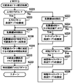
図9に示すように、発展A−1〜発展A−3の可変表示パターンでは、第1リーチ〜第3リーチに対応するリーチ演出表示を、第1リーチ→第2リーチ→第3リーチの順番という、所定順序で紹介することができ、動画像により紹介のあった最後のリーチに対応するリーチ演出表示が実行される。すなわち、発展A−1の可変表示パターンでは、第1リーチのみが紹介され、第1リーチに対応するリーチ演出表示が実行される。発展A−2の可変表示パターンでは、第1リーチと第2リーチが紹介され、最後に紹介された第2リーチに対応するリーチ演出表示が実行される。発展A−3の可変表示パターンでは、第1リーチ〜第3リーチが全て紹介され、最後に紹介された第3リーチに対応するリーチ演出表示が実行される。 As shown in FIG. 9, in the variable display patterns of development A-1 to development A-3, the reach effect display corresponding to the first reach to the third reach is displayed in the order of the first reach → second reach → third reach. The reach effect display corresponding to the last reach introduced by the moving image can be executed. That is, in the variable display pattern of the development A-1, only the first reach is introduced, and the reach effect display corresponding to the first reach is executed. In the variable display pattern of the development A-2, the first reach and the second reach are introduced, and the reach effect display corresponding to the last introduced second reach is executed. In the variable display pattern of development A-3, the first reach to the third reach are all introduced, and reach effect display corresponding to the third reach introduced last is executed.
発展B−1〜発展B−3の可変表示パターンでは、第1リーチ〜第3リーチに対応するリーチ演出表示を、第2リーチ→第1リーチ→第3リーチの順番という、発展A−1〜発展A−3の可変表示パターンにおける所定順序とは異なる特殊順序で紹介することができ、動画像により紹介のあった最後のリーチに対応するリーチ演出表示が実行される。すなわち、発展B−1の可変表示パターンでは、第2リーチのみが紹介され、第2リーチに対応するリーチ演出表示が実行される。発展B−2の可変表示パターンでは、第2リーチと第1リーチが紹介され、最後に紹介された第1リーチに対応するリーチ演出表示が実行される。発展B−3の可変表示パターンでは、第1リーチ〜第3リーチが全て紹介され、最後に紹介された第3リーチに対応するリーチ演出表示が実行される。 In the variable display pattern of development B-1 to development B-3, the reach effect display corresponding to the first reach to the third reach is represented by the development A-1 to the order of the second reach → the first reach → the third reach. The special display order different from the predetermined order in the variable display pattern of the development A-3 can be introduced, and the reach effect display corresponding to the last reach introduced by the moving image is executed. That is, in the variable display pattern of the development B-1, only the second reach is introduced, and the reach effect display corresponding to the second reach is executed. In the variable display pattern of development B-2, the second reach and the first reach are introduced, and the reach effect display corresponding to the last introduced first reach is executed. In the variable display pattern of development B-3, the first reach to the third reach are all introduced, and reach effect display corresponding to the third reach introduced last is executed.
発展C−1〜発展C−3の可変表示パターンでは、第1リーチ〜第3リーチに対応するリーチ演出表示を、第1リーチ→第2リーチ→第3リーチの順番という、発展A−1〜発展A−3の可変表示パターンにおける所定順序と同一の順序で紹介することができる一方で、動画像により紹介のあった最後のリーチとは異なるリーチに対応するリーチ演出表示が実行される。すなわち、発展C−1の可変表示パターンでは、第1リーチのみが紹介され、紹介のあった第1リーチとは異なる第2リーチに対応するリーチ演出表示が実行される。発展C−2の可変表示パターンでは、第1リーチと第2リーチが紹介され、最後に紹介された第2リーチとは異なる第3リーチに対応するリーチ演出表示が実行される。発展C−3の可変表示パターンでは、第1リーチ〜第3リーチが全て紹介され、最後に紹介された第3リーチとは異なる第1リーチに対応するリーチ演出表示が実行される。 In the variable display patterns of development C-1 to development C-3, the reach effect display corresponding to the first reach to the third reach is represented by the development A-1 to the order of the first reach → the second reach → the third reach. While it is possible to introduce in the same order as the predetermined order in the variable display pattern of development A-3, reach effect display corresponding to a reach different from the last reach introduced by the moving image is executed. In other words, in the variable display pattern of development C-1, only the first reach is introduced, and reach effect display corresponding to the second reach different from the introduced first reach is executed. In the variable display pattern of development C-2, the first reach and the second reach are introduced, and the reach effect display corresponding to the third reach different from the last introduced second reach is executed. In the variable display pattern of the development C-3, all of the first reach to the third reach are introduced, and the reach effect display corresponding to the first reach different from the third reach introduced last is executed.
図10は、第1リーチに対応するリーチ演出表示の一例を示している。第1リーチとなる場合には、例えば図10(A)に示すような飾り図柄「6」及び「7」といった、「左」及び「右」の可変表示部にて同一の飾り図柄が、斜め方向の有効ラインといった所定の有効ライン上に停止してリーチが成立した後に、動画像によりリーチ演出表示を紹介するリーチ紹介が行われる。このときには、「左」及び「右」の可変表示部にて停止している飾り図柄を縮小して、画像表示装置5の画面内における外縁部に表示させればよい。こうしてリーチ紹介が終了すると、例えば図10(B)に示すように「中」の可変表示部にて停止した飾り図柄「5」に流星が衝突するような演出表示を行い、図10(C)に示すように「中」の可変表示部にて停止した飾り図柄「5」が破壊されるような演出表示を行う。続いて、例えば図10(D)に示すように「中」の可変表示部にて飾り図柄「6」を停止させることや、「中」の可変表示部に停止した飾り図柄に再び流星が衝突するような演出表示を行うことなどにより、飾り図柄の可変表示を進行させる。
FIG. 10 shows an example of reach effect display corresponding to the first reach. In the case of the first reach, for example, the same decorative design is obliquely displayed on the “left” and “right” variable display sections such as the decorative designs “6” and “7” as shown in FIG. After reaching a predetermined effective line such as a directional effective line and reaching a reach, reach introduction is performed to introduce a reach effect display using a moving image. At this time, the decorative symbols stopped at the “left” and “right” variable display portions may be reduced and displayed on the outer edge portion in the screen of the
その後、リーチハズレパターンとなる可変表示パターンに対応する飾り図柄の可変表示結果としてハズレ組合せの確定飾り図柄を導出表示する場合には、例えば図10(E)に示すような飾り図柄「8」といった、所定の有効ライン上における「左」及び「右」の可変表示部に揃って停止することでリーチを成立させている飾り図柄とは異なる飾り図柄を、リーチが成立している有効ライン上における「中」の可変表示部に停止させる。これに対して、大当りパターンとなる可変表示パターンに対応する飾り図柄の可変表示結果として大当り組合せの確定飾り図柄を導出表示する場合には、例えば図10(F)に示すような飾り図柄「7」といった、リーチとなっている飾り図柄と同一の飾り図柄を、リーチが成立している有効ライン上における「中」の可変表示部に停止させる。 Thereafter, in the case of deriving and displaying the final decorative pattern of the lost combination as the variable display result of the decorative pattern corresponding to the variable display pattern that becomes the reach lose pattern, for example, a decorative pattern “8” as shown in FIG. A decorative pattern different from the decorative pattern that has reached reach by stopping together with the variable display portions of “left” and “right” on a predetermined active line is displayed on the active line on which reach has been established. Stop at the middle display. On the other hand, in the case of deriving and displaying a definite decorative combination of jackpot combination as a variable display result of the decorative pattern corresponding to the variable display pattern serving as the jackpot pattern, for example, a decorative pattern “7” as shown in FIG. ”Is stopped on the“ medium ”variable display section on the active line where the reach is established.
図11は、第2リーチに対応するリーチ演出表示の一例を示している。第2リーチとなる場合には、例えば図11(A)に示すような飾り図柄「6」及び「7」といった、「左」及び「右」の可変表示部にて同一の飾り図柄が、斜め方向の有効ラインといった所定の有効ライン上に停止してリーチが成立した後に、動画像によりリーチ演出表示を紹介するリーチ紹介が行われる。このときには、「左」及び「右」の可変表示部にて停止している飾り図柄を縮小して、画像表示装置5の画面内における外縁部に表示させればよい。こうしてリーチ紹介が終了すると、例えば図11(B)に示すように「中」の可変表示部にて停止した飾り図柄「5」とともに雨が降る様子を示す演出表示を行い、図11(C)に示すように「中」の可変表示部にて停止した飾り図柄「5」が雷光により消去されるような演出表示を行う。続いて、例えば図11(D)に示すように「中」の可変表示部にて飾り図柄「6」を停止させることや、「中」の可変表示部にて停止した飾り図柄が雷光により再び消去されるような演出表示を行うことなどにより、飾り図柄の可変表示を進行させる。
FIG. 11 shows an example of reach effect display corresponding to the second reach. In the case of the second reach, for example, the same decorative design is obliquely displayed on the “left” and “right” variable display sections such as the decorative designs “6” and “7” as shown in FIG. After reaching a predetermined effective line such as a directional effective line and reaching a reach, reach introduction is performed to introduce a reach effect display using a moving image. At this time, the decorative symbols stopped at the “left” and “right” variable display portions may be reduced and displayed on the outer edge portion in the screen of the
その後、リーチハズレパターンとなる可変表示パターンに対応する飾り図柄の可変表示結果としてハズレ組合せの確定飾り図柄を導出表示する場合には、例えば図11(E)に示すような飾り図柄「8」といった、所定の有効ライン上における「左」及び「右」の可変表示部に揃って停止することでリーチを成立させている飾り図柄とは異なる飾り図柄を、リーチが成立している有効ライン上における「中」の可変表示部に停止させる。これに対して、大当りパターンとなる可変表示パターンに対応する飾り図柄の可変表示結果として大当り組合せの確定飾り図柄を導出表示する場合には、例えば図11(F)に示すような飾り図柄「7」といった、リーチとなっている飾り図柄と同一の飾り図柄を、リーチが成立している有効ライン上における「中」の可変表示部に停止させる。 Thereafter, in the case of deriving and displaying the final decorative pattern of the lost combination as the variable display result of the decorative pattern corresponding to the variable display pattern serving as the reach loss pattern, for example, a decorative pattern “8” as shown in FIG. A decorative pattern different from the decorative pattern that has reached reach by stopping together with the variable display portions of “left” and “right” on a predetermined active line is displayed on the active line on which reach has been established. Stop at the middle display. On the other hand, in the case of deriving and displaying the definite decorative combination of the jackpot combination as the variable display result of the decorative pattern corresponding to the variable display pattern serving as the jackpot pattern, for example, the decorative pattern “7” as shown in FIG. ”Is stopped on the“ medium ”variable display section on the active line where the reach is established.
図12は、第3リーチに対応するリーチ演出表示の一例を示している。第3リーチとなる場合には、例えば図12(A)に示すような飾り図柄「6」及び「7」といった、「左」及び「右」の可変表示部にて同一の飾り図柄が、斜め方向の有効ラインといった所定の有効ライン上に停止してリーチが成立した後に、動画像によりリーチ演出表示を紹介するリーチ紹介が行われる。このときには、「左」及び「右」の可変表示部にて停止している飾り図柄を縮小して、画像表示装置5の画面内における外縁部に表示させればよい。こうしてリーチ紹介が終了すると、例えば図12(B)に示すように「中」の可変表示部にて停止した飾り図柄「5」とともに日の出を示す演出表示を行い、図12(C)に示すように「中」の可変表示部にて停止した飾り図柄「5」が太陽により消去されるような演出表示を行う。続いて、例えば図12(D)に示すように「中」の可変表示部にて飾り図柄「6」を停止させることや、「中」の可変表示部にて停止した飾り図柄が太陽により再び消去されるような演出表示を行うことなどにより、飾り図柄の可変表示を進行させる。
FIG. 12 shows an example of reach effect display corresponding to the third reach. In the case of the third reach, for example, the same decorative design is diagonally displayed on the “left” and “right” variable display sections such as the decorative designs “6” and “7” as shown in FIG. After reaching a predetermined effective line such as a directional effective line and reaching a reach, reach introduction is performed to introduce a reach effect display using a moving image. At this time, the decorative symbols stopped at the “left” and “right” variable display portions may be reduced and displayed on the outer edge portion in the screen of the
その後、リーチハズレパターンとなる可変表示パターンに対応する飾り図柄の可変表示結果としてハズレ組合せの確定飾り図柄を導出表示する場合には、例えば図12(E)に示すような飾り図柄「8」といった、所定の有効ライン上における「左」及び「右」の可変表示部に揃って停止することでリーチを成立させている飾り図柄とは異なる飾り図柄を、リーチが成立している有効ライン上における「中」の可変表示部に停止させる。これに対して、大当りパターンとなる可変表示パターンに対応する飾り図柄の可変表示結果として大当り組合せの確定飾り図柄を導出表示する場合には、例えば図12(F)に示すような飾り図柄「7」といった、リーチとなっている飾り図柄と同一の飾り図柄を、リーチが成立している有効ライン上における「中」の可変表示部に停止させる。 Thereafter, in the case of deriving and displaying the final decorative pattern of the lost combination as the variable display result of the decorative pattern corresponding to the variable display pattern serving as the reach loss pattern, for example, a decorative pattern “8” as shown in FIG. A decorative pattern different from the decorative pattern that has reached reach by stopping together with the variable display portions of “left” and “right” on a predetermined active line is displayed on the active line on which reach has been established. Stop at the middle display. On the other hand, in the case of deriving and displaying the definite decorative combination of the jackpot combination as the variable display result of the decorative pattern corresponding to the variable display pattern serving as the jackpot pattern, for example, the decorative pattern “7” as shown in FIG. ”Is stopped on the“ medium ”variable display section on the active line where the reach is established.
なお、図10〜図12に示すリーチ演出表示は、パチンコ遊技機1における演出状態が第1演出モードであるときに実行される一方で、第2演出モードや第3演出モードであるときには、図10〜図12に示すリーチ演出表示とは演出表示態様が異なるリーチ演出表示が行われるようにしてもよい。
The reach effect display shown in FIGS. 10 to 12 is executed when the effect state in the
図4に示す遊技制御用マイクロコンピュータ100のROM112に格納される可変表示パターン決定テーブルの具体的な一例として、この実施の形態では、図13(A)に示す通常時ハズレパターン決定テーブル220Aと、図13(B)に示す時短中ハズレパターン決定テーブル220Bと、図13(C)に示すリーチハズレパターン決定テーブル220Cと、図13(D)に示す大当りパターン決定テーブル220Dとが用意されている。
As a specific example of the variable display pattern determination table stored in the
図13(A)に示す通常時ハズレパターン決定テーブル220Aは、通常遊技状態において特別図柄や飾り図柄の可変表示結果をハズレとする旨の決定がなされたときに、飾り図柄の可変表示態様をリーチとしない旨の決定がなされたことに対応して、可変表示パターン決定用の乱数値MR3に基づき、複数種類ある通常時ハズレパターンのいずれかを選択決定できるように構成されている。図13(B)に示す時短中ハズレパターン決定テーブル220Bは、確変遊技状態や時間短縮状態といった時短制御が行われる特別遊技状態において特別図柄や飾り図柄の可変表示結果をハズレとする旨の決定がなされたときに、飾り図柄の可変表示態様をリーチとしない旨の決定がなされたことに対応して、可変表示パターン決定用の乱数値MR3に基づき、複数種類ある時短中ハズレパターンのいずれかを選択決定できるように構成されている。 The normal-time losing pattern determination table 220A shown in FIG. 13A reaches the variable display mode of decorative symbols when it is determined that the variable display result of special symbols or decorative symbols is lost in the normal gaming state. Corresponding to the determination that no change is made, one of a plurality of types of normal-time loss patterns can be selected and determined based on the random display pattern MR3 for determining the variable display pattern. The short / medium loss pattern determination table 220B shown in FIG. 13 (B) determines that the variable display result of the special symbol or the decorative symbol is lost in the special game state in which the short time control is performed such as the probability variation game state or the time reduction state. In response to the decision not to reach the variable display mode of the decorative design when it is made, any one of a plurality of types of short / short / long / short lose patterns based on the random value MR3 for determining the variable display pattern is selected. It is configured so that selection can be made.
図13(C)に示すリーチハズレパターン決定テーブル220Cは、特別図柄や飾り図柄の可変表示結果をハズレとする旨の決定がなされたときに、飾り図柄の可変表示態様をリーチとする旨の決定がなされたことに対応して、可変表示パターン決定用の乱数値MR3に基づき、複数種類あるリーチハズレパターンのいずれかを選択決定できるように構成されている。図13(D)に示す大当りパターン決定テーブル220Dは、特別図柄や飾り図柄の可変表示結果を大当りとする旨の決定がなされたときに、可変表示パターン決定用の乱数値MR3に基づいて、複数種類ある大当りパターンのいずれかを選択決定できるように構成されている。 In the reach loss pattern determination table 220C shown in FIG. 13C, when it is determined that the variable display result of the special symbol or the decorative symbol is to be lost, the determination that the variable display mode of the decorative symbol is to be reached is made. Corresponding to what has been done, one of a plurality of types of reach / loss patterns can be selected and determined based on the random value MR3 for determining the variable display pattern. The jackpot pattern determination table 220D shown in FIG. 13D includes a plurality of jackpot pattern determination tables 220D based on the random display value MR3 for determining the variable display pattern when it is determined that the variable display result of the special symbol or the decorative symbol is a jackpot. It is configured so that one of various types of big hit patterns can be selected and determined.
ここで、図13(C)に示すリーチハズレパターン決定テーブル220Cと図13(D)に示す大当りパターン決定テーブル220Dとを比べると、ノーマル、発展A−1〜発展A−3、発展B−1〜発展B−3、発展C−1〜発展C−3というリーチの種類に対応した各可変表示パターンに対する可変表示パターン決定用の乱数値MR3の割当てが、異なっている。これにより、特別図柄や飾り図柄の可変表示結果がハズレとなるか、大当りとなるかに応じて、選択されるリーチ種類の割合が異なるものとなり、表示結果が大当りとなる確率は、特別図柄や飾り図柄の可変表示パターンに応じて異なるものとなる。このように、可変表示パターンに対応して決められる大当りとなる確率は、リーチの大当り信頼度、あるいは単に、リーチの信頼度とも称される。 Here, when the reach loss pattern determination table 220C shown in FIG. 13C and the jackpot pattern determination table 220D shown in FIG. 13D are compared, normal, development A-1 to development A-3, development B-1 to The allocation of the random display value MR3 for determining the variable display pattern to each variable display pattern corresponding to the types of reach B-3 and C-1 to C-3 is different. As a result, depending on whether the variable display result of special symbols or decorative symbols is lost or a big hit, the percentage of reach types selected will be different, and the probability that the display result will be a big hit is the special symbol or It differs depending on the variable display pattern of the decorative design. In this way, the probability of a big hit determined corresponding to the variable display pattern is also referred to as a reach big hit reliability or simply as a reach reliability.
図14は、ノーマル、発展A−1〜発展A−3、発展B−1〜発展B−3、発展C−1〜発展C−3の各可変表示パターンについて、特別図柄や飾り図柄の可変表示結果をハズレとする旨の決定がなされたハズレ時や可変表示結果を大当りとする旨の決定がなされた大当り時における選択確率と、パチンコ遊技機1における遊技状態が通常遊技状態であるときや確変遊技状態であるときにおけるリーチの信頼度とを示す説明図である。なお、図14に示すリーチの信頼度は、通常遊技状態における大当り確率が1/300であり、確変遊技状態における大当り確率が1/30であり、ハズレ時のリーチ出現率が1/10であるものとして算出したものである。また、時間短縮状態では大当り確率が通常遊技状態と同じであることから、リーチの信頼度も通常遊技状態のときと同じである。各可変表示パターンに対応するリーチの信頼度は、((大当り時における当該可変表示パターンの選択確率)×(大当り確率))/((ハズレ時における当該可変表示パターンの選択確率)×(ハズレ確率)×(リーチ出現率)+(大当り時における当該可変表示パターンの選択確率)×(大当り確率))として求めることができる。なお、(ハズレ確率)=1−(大当り確率)である。
FIG. 14 shows variable display of special symbols and decorative symbols for the variable display patterns of normal, development A-1 to development A-3, development B-1 to development B-3, and development C-1 to development C-3. The selection probability at the time of losing when the result is determined to be lost or when the variable display result is determined to be a big hit, and when the gaming state in the
この実施の形態では、図14に示すように、発展A−1〜発展A−3の可変表示パターンに比べて発展B−1〜発展B−3の可変表示パターンの方がいずれもリーチの信頼度が高く、また、発展A−1〜発展A−3の可変表示パターンに比べて発展C−1〜発展C−3の可変表示パターンの方がいずれもリーチの信頼度が高くなるように、図13(C)に示すリーチハズレパターン決定テーブル220Cと図13(D)に示す大当りパターン決定テーブル220Dにて乱数値MR3を各可変表示パターンと対応付けるテーブルデータ(決定用データ)が構成されている。これにより、第1リーチ→第2リーチ→第3リーチの順番という所定順序とは異なる第2リーチ→第1リーチ→第3リーチの順番という特殊順序でリーチ演出表示が紹介されたときの方が、所定順序でリーチ演出表示が紹介されたときよりも表示結果が大当りとなる確率は高くなる。また、動画像により紹介のあった最後のリーチとは異なるリーチに対応するリーチ演出表示が実行されたときの方が、動画像により紹介のあった最後のリーチに対応するリーチ演出表示が実行されたときよりも表示結果が大当りとなる確率は高くなる。 In this embodiment, as shown in FIG. 14, the variable display patterns of developments B-1 to B-3 are more reliable than the variable display patterns of developments A-1 to A-3. The degree of reach is higher in the variable display patterns of development C-1 to development C-3 than in the variable display patterns of development A-1 to development A-3. Table data (determination data) for associating the random value MR3 with each variable display pattern is constituted by the reach loss pattern determination table 220C shown in FIG. 13C and the big hit pattern determination table 220D shown in FIG. Thus, when the reach effect display is introduced in a special order of the second reach, the first reach, and the third reach, which is different from the predetermined order of the first reach, the second reach, and the third reach. The probability that the display result is a big hit is higher than when the reach effect display is introduced in a predetermined order. In addition, when the reach effect display corresponding to the reach that is different from the last reach introduced by the moving image is executed, the reach effect display corresponding to the last reach introduced by the moving image is executed. There is a higher probability that the display result will be a big hit than when it is.
図4に示す遊技制御用マイクロコンピュータ100のROM112に格納されるコマンドテーブルの一例として、この実施の形態では、図15に示すような可変表示開始用コマンドテーブル230が用意されている。可変表示開始用コマンドテーブル230は、特別図柄や飾り図柄の可変表示を開始する際に主基板11から演出制御基板12に対して各種の演出制御コマンドを送信するための設定データなどから構成されている。図15に示す例では、可変表示開始用コマンドテーブル230を構成する設定データとして、可変表示開始コマンド用設定データ、表示結果通知コマンド用設定データ、特図保留記憶数通知コマンド用設定データ、終了コードが含まれている。可変表示開始コマンド用設定データは、主基板11から演出制御基板12に対して可変表示開始コマンドを送信するために用いられる設定データである。表示結果通知コマンド用設定データは、主基板11から演出制御基板12に対して表示結果通知コマンドを送信するために用いられる設定データである。特図保留記憶数通知コマンド用設定データは、主基板11から演出制御基板12に対して特図保留記憶数通知コマンドを送信するために用いられる設定データである。なお、可変表示開始用コマンドテーブル230などのコマンドテーブルは終了コードを含まないように構成し、主基板11と演出制御基板12との間での送受信バイト数が規定バイト数に達したことに対応して、各コマンドテーブルに基づくコマンドの送受信が完了したと判断してもよい。
As an example of the command table stored in the
図4に示す遊技制御用マイクロコンピュータ100のRAM113には、パチンコ遊技機1における遊技状態などを制御するために用いられる各種のデータを保持する領域として、例えば図16に示すような遊技制御用データ保持エリア240が設けられている。図16に示す遊技制御用データ保持エリア240は、特図保留記憶部161と、遊技制御フラグ設定部162と、遊技制御タイマ設定部163と、遊技制御カウンタ設定部164と、遊技制御バッファ設定部165とを備えている。
In the
特図保留記憶部161は、普通可変入賞球装置6が形成する始動入賞口に遊技球が入賞して特別図柄表示装置4による特図ゲームや画像表示装置5における飾り図柄の可変表示を実行するための実行条件が成立したものの、従前の特図ゲーム等を実行中であるなどの理由により可変表示を開始するための開始条件が成立していない特図ゲームに関する保留情報を記憶する。例えば、特図保留記憶部161は、始動入賞口への入賞順に保留番号と関連付けて、その入賞による実行条件の成立に基づいてCPU111により乱数回路114等から抽出された特図表示結果判定用の乱数値MR1を示す数値データや大当り種別決定用の乱数値MR4を示す数値データを保留データとし、その数が所定の上限値(例えば「4」)に達するまで記憶する。
The special figure holding
遊技制御フラグ設定部162には、例えば特別図柄プロセスフラグや大当りフラグ、確変フラグ、時短フラグ、コマンド送信済みフラグなどが設けられている。
The game control
特別図柄プロセスフラグは、特別図柄表示装置4における特図ゲームの進行等を制御するために実行される特別図柄プロセス処理(図27のステップS15、図28)において、どの処理を選択・実行すべきかを指示する。大当りフラグは、特別図柄や飾り図柄の可変表示結果を「通常大当り」や「確変大当り」といった大当りとする旨の決定がなされたことに対応してオン状態にセットされる一方で、その決定に基づく特図ゲームが終了したことに対応してクリアされてオフ状態となる。確変フラグは、パチンコ遊技機1における遊技状態が確変遊技状態に制御されることに対応してオン状態にセットされる一方で、特別図柄や飾り図柄の可変表示結果が「通常大当り」や「確変大当り」といった大当りとなることに対応して、クリアされてオフ状態となる。時短フラグは、パチンコ遊技機1における遊技状態が確変遊技状態や時間短縮状態といった時短制御が行われる特別遊技状態となることに対応してオン状態にセットされる。その一方で、時短フラグは、時間短縮状態が終了すること、または、特別図柄や飾り図柄の可変表示結果が「大当り」となることに対応して、クリアされてオフ状態となる。コマンド送信済みフラグは、特別図柄表示装置4における特図ゲームの終了後や大当り遊技状態の終了後に主基板11から演出制御基板12に対して背景指定コマンドの送信が行われることに対応してオン状態にセットされる。その一方で、コマンド送信済みフラグは、特別図柄表示装置4における特図ゲームが開始されることなどに対応してクリアされてオフ状態となる。
The special symbol process flag indicates which process should be selected / executed in the special symbol process (step S15 in FIG. 27, FIG. 28) that is executed to control the progress of the special symbol game in the special
遊技制御タイマ設定部163には、例えば特別図柄プロセスタイマなどが設けられている。特別図柄プロセスタイマは、例えば特図ゲームの実行時間である特別図柄の可変表示時間といった特図ゲームの進行を制御するための時間や、大当り遊技状態の進行を制御するための時間などを、主基板11の側にて計測するためのものである。例えば、特別図柄プロセスタイマは、特図ゲームの進行や大当り遊技状態の進行を制御するために計測する時間に対応したタイマ値データを、特別図柄プロセスタイマ値として記憶し、定期的にカウントダウンするダウンカウンタとして用いられる。
The game control
遊技制御カウンタ設定部164には、例えば特図保留記憶数カウンタや時短回数カウンタなどが設けられている。特図保留記憶数カウンタは、普通可変入賞球装置6が形成する始動入賞口への遊技球の入賞に基づく特図保留記憶部161における保留データの数である特図保留記憶数をカウントするためのものである。例えば、特図保留記憶数カウンタは、特図保留記憶数に対応したカウント値データを、特図保留記憶数カウント値として記憶し、特図保留記憶数の増減に対応して更新(例えば1加算あるいは1減算)される。時短回数カウンタは、パチンコ遊技機1が時間短縮状態にて実行可能な特図ゲームの残り回数をカウントするためのものである。時短回数カウンタには、大当り遊技状態の終了後に時間短縮状態が開始されることに対応して、時間短縮状態にて実行可能として予め定められた特図ゲームの回数(例えば「100」)に対応したカウント初期値データ(例えば「64H」)が、時短回数カウント値として設定される。そして、時間短縮状態にて可変表示結果が「ハズレ」となる特図ゲームが終了するごとに、時短回数カウント値が更新(例えば1減算)される。
The game control
遊技制御バッファ設定部165には、例えば表示結果判定用バッファや大当り種別判定バッファ、大当り開始情報バッファ、大当り終了情報バッファ、遊技状態指定バッファ、パターンデータバッファ、確定特別図柄バッファなどが設けられている。
The game control
表示結果判定用バッファには、特図ゲームの開始条件が成立したときに、特図保留記憶部161から読み出された乱数値MR1や乱数値MR4を示すデータが、表示結果判定用バッファ値としてセットされる。この表示結果判定用バッファ値により、特別図柄や飾り図柄の可変表示結果を「大当り」とするか「ハズレ」とするかの判定などを可能にする。大当り種別判定バッファには、可変表示結果を「通常大当り」と「確変大当り」のいずれとするかの特図事前決定結果といった、大当り種別の決定結果に対応した値を示すデータが、大当り種別判定バッファ値としてセットされる。
In the display result determination buffer, the data indicating the random value MR1 and the random value MR4 read from the special figure holding
大当り開始情報バッファには、大当り種別の決定結果に対応したデータが、大当り開始情報バッファ値としてセットされる。そして、大当り開始情報バッファ値は、大当り開始コマンドにおけるEXTデータとなる設定データとして用いられる。大当り終了情報バッファには、大当り種別の決定結果に対応したデータが、大当り終了情報バッファ値としてセットされる。そして、大当り終了情報バッファ値は、大当り終了コマンドにおけるEXTデータとなる設定データとして用いられる。 In the jackpot start information buffer, data corresponding to the determination result of the jackpot type is set as a jackpot start information buffer value. The jackpot start information buffer value is used as setting data to be EXT data in the jackpot start command. In the jackpot end information buffer, data corresponding to the determination result of the jackpot type is set as a jackpot end information buffer value. The jackpot end information buffer value is used as setting data to be EXT data in the jackpot end command.
遊技状態指定バッファには、パチンコ遊技機1における遊技状態が通常遊技状態であるか確変遊技状態であるか時間短縮状態であるかに対応したデータが、遊技状態指定バッファ値としてセットされる。すなわち、パチンコ遊技機1における遊技状態が通常遊技状態である場合には、遊技状態指定バッファに「00H」を示すデータがセットされる。パチンコ遊技機1における遊技状態が確変遊技状態である場合には、遊技状態指定バッファに「01H」を示すデータがセットされる。パチンコ遊技機1における遊技状態が時間短縮状態である場合には、遊技状態指定バッファに「02H」を示すデータがセットされる。遊技状態指定バッファにセットされたデータは、背景指定コマンドにおけるEXTデータとなる設定データとして用いられる。
In the gaming state designation buffer, data corresponding to whether the gaming state in the
パターンデータバッファには、特別図柄や飾り図柄の可変表示パターンを示す可変表示開始コマンドにおいてEXTデータとして設定されるデータが、パターンデータバッファ値としてセットされる。確定特別図柄バッファには、例えば特図ゲームにおける特別図柄の可変表示結果として導出表示することに決定された確定特別図柄や大当り種別などに対応したデータが、確定特別図柄バッファ値としてセットされる。確定特別図柄バッファ値は、表示結果通知コマンドにおけるEXTデータとなる設定データとして用いられるデータであってもよい。 In the pattern data buffer, data set as the EXT data in the variable display start command indicating the variable display pattern of the special symbol or the decorative symbol is set as the pattern data buffer value. In the fixed special symbol buffer, for example, data corresponding to a fixed special symbol or a jackpot type determined to be derived and displayed as a variable display result of the special symbol in the special symbol game is set as a fixed special symbol buffer value. The confirmed special symbol buffer value may be data used as setting data to be EXT data in the display result notification command.
図4に示す遊技制御用マイクロコンピュータ100の入出力ポート115は、遊技制御用マイクロコンピュータ100に伝送された各種信号を取り込むための入力ポートと、遊技制御用マイクロコンピュータ100の外部へと各種信号を伝送するための出力ポートとを含んで構成されている。
The input /
図2に示す演出制御基板12は、主基板11とは独立したサブ側の制御基板であり、信号中継基板14を介するなどして主基板11から伝送された演出制御コマンドを受信し、画像表示装置5、スピーカ8L、8R及び遊技効果ランプ9といった演出用の電気部品を制御するための各種回路が搭載されている。すなわち、演出制御基板12は、画像表示装置5における表示動作の全部または一部や、スピーカ8L、8Rからの音声出力動作、遊技効果ランプ9におけるランプの点灯動作及び消灯動作などといった、演出用の電気部品に所定の演出動作を実行させるための制御内容を決定する機能を備えている。
The
演出制御基板12には、表示制御基板13に対して表示制御用のコマンド(表示制御指令)を伝送するための配線や、スピーカ8L、8R及び遊技効果ランプ9に駆動信号を伝送する配線などが接続されている。図2に示すように、演出制御基板12には、演出制御用マイクロコンピュータ120と、音制御部121と、ランプ制御部122とが搭載されている。
The
図17は、演出制御基板12に搭載された演出制御用マイクロコンピュータ120の構成例を示す図である。図17に示す演出制御用マイクロコンピュータ120は、例えば1チップマイクロコンピュータであり、プログラムに従って制御動作を行うCPU131と、演出制御用のプログラムや固定データ等を記憶するROM132と、CPU131のワークエリアを提供するRAM133と、CPU131とは独立して乱数値を示す数値データの更新を行う乱数回路134と、入出力ポート135とを備えている。演出制御用マイクロコンピュータ120では、CPU131がROM132から読み出したプログラムを実行し、RAM133をワークエリアとして用いることで、演出用の電気部品を制御するための処理が実行される。
FIG. 17 is a diagram illustrating a configuration example of the
乱数回路134は、演出制御基板12の側において用いられる各種の乱数の全てまたは一部を生成する回路である。図18は、演出制御基板12の側において用いられる乱数値を例示する説明図である。図18に示すように、この実施の形態では、演出制御基板12の側において、大当り中昇格成功演出実行決定用の乱数値SR1、大当り中昇格失敗演出実行決定用の乱数値SR2、エンディング昇格失敗演出実行決定用の乱数値SR3が用いられ、これらの乱数値を示す数値データがカウント可能となるように制御される。なお、演出効果を高めるために、演出制御基板12の側でこれら以外の乱数値が用いられてもよい。これらの乱数値SR1〜SR3の全部または一部を示す数値データが、乱数回路134にてカウントされればよい。また、乱数値SR1〜SR3の一部を示す数値データは、CPU131が乱数回路134とは異なるランダムカウンタを用いて、ソフトウェアによる更新によってカウントするようにしてもよい。
The
大当り中昇格成功演出実行決定用の乱数値SR1は、大当り遊技状態の終了時より前の所定タイミングにて、大当り中昇格成功演出を実行するか否かを決定するために用いられる乱数値であり、例えば「1」〜「100」の範囲の値をとる。大当り中昇格失敗演出実行決定用の乱数値SR2は、大当り遊技状態の終了時より前の所定タイミングにて、大当り中昇格失敗演出を実行するか否かを決定するために用いられる乱数値であり、例えば「1」〜「100」の範囲の値をとる。エンディング昇格失敗演出実行決定用の乱数値SR3は、大当り遊技状態の終了時となる所定のタイミングにて、エンディング昇格失敗演出を実行するか否かを判定するために用いられる乱数値であり、例えば「1」〜「100」の範囲の値をとる。 The random value SR1 for determining the execution of the big hit success promotion effect is a random value used to determine whether or not to execute the big success promotion effect at a predetermined timing before the end of the big hit gaming state. For example, a value in the range of “1” to “100” is taken. The random value SR2 for determining the execution of the jackpot promotion promotion effect is a random value used to determine whether or not to execute the jackpot promotion promotion effect at a predetermined timing before the end of the jackpot gaming state. For example, a value in the range of “1” to “100” is taken. The random value SR3 for determining the ending promotion failure production execution is a random value used for determining whether or not to execute the ending promotion failure production at a predetermined timing when the jackpot gaming state ends. It takes a value in the range of “1” to “100”.
ROM132には、CPU131による制御動作において各種の決定や判定を行うために読出可能なデータとして、例えば複数種類の飾り図柄決定テーブルや演出実行決定テーブル、演出制御パターンテーブルといった、各種のテーブルを構成するデータが記憶されている。飾り図柄決定テーブルは、画像表示装置5における飾り図柄の可変表示結果として導出表示される確定飾り図柄などを決定するために用いられるテーブルである。演出決定テーブルは、演出制御基板12の側において、所定の演出動作を実行するか否かや、実行する場合における演出動作の態様を示す演出パターンなどを決定するために用いられるテーブルである。
In the
ROM132に格納される演出制御パターンテーブルの具体的な一例として、この実施の形態では、例えば図19に示すような演出制御パターンテーブル300A〜300Dが用いられる。各演出制御パターンテーブル300A〜300Dには、表示制御基板13に対して送信する表示制御指令を示すデータや、スピーカ8L、8R等の音声出力制御の内容、遊技効果ランプ9等による演出内容といった、各種の演出制御の内容を示すデータが、演出制御パターンとして複数種類格納されていればよい。各演出制御パターンは、例えば図20に示すように、演出制御プロセスタイマ設定値、演出制御プロセスタイマ判定値#1〜#n(nは任意の自然数)、表示制御データ#1〜#n、音声制御データ#1〜#n、ランプ制御データ#1〜#n、終了コードといった、演出動作を制御するための各種データから構成され、時系列的に、表示制御基板13に対して送信する表示制御指令や、スピーカ8L、8Rからの音声出力内容、遊技効果ランプ9による演出内容といった、各種の演出制御の内容や、演出制御の切換タイミング等が設定されている。
As a specific example of the effect control pattern table stored in the
図19に示す演出制御パターンテーブル300Aは、パチンコ遊技機1における演出状態が第1演出モード〜第3演出モードのうち第1演出モードに設定されている場合において飾り図柄の可変表示時に用いられる演出制御パターンが複数種類格納された第1演出モード時可変表示用のパターンテーブルである。例えば図21に示すように、演出制御パターンテーブル300Aには、パチンコ遊技機1における演出状態が第1演出モードに設定されているときに、各可変表示パターンに対応して演出制御の内容を示す演出制御パターンが格納されている。
The effect control pattern table 300A shown in FIG. 19 is an effect that is used during variable display of decorative symbols when the effect state in the
図19に示す演出制御パターンテーブル300Bは、パチンコ遊技機1における演出状態が第1演出モード〜第3演出モードのうち第2演出モードに設定されている場合において飾り図柄の可変表示時に用いられる演出制御パターンが複数種類格納された第2演出モード時可変表示用のパターンテーブルである。例えば、演出制御パターンテーブル300Bには、パチンコ遊技機1における演出状態が第2演出モードに設定されているときに、各可変表示パターンに対応して演出制御の内容を示す演出制御パターンが格納されている。
The effect control pattern table 300B shown in FIG. 19 is an effect that is used during variable display of decorative symbols when the effect state in the
図19に示す演出制御パターンテーブル300Cは、パチンコ遊技機1における演出状態が第1演出モード〜第3演出モードのうち第3演出モードに設定されている場合において飾り図柄の可変表示時に用いられる演出制御パターンが複数種類格納された第3演出モード時可変表示用のパターンテーブルである。例えば、演出制御パターンテーブル300Cには、パチンコ遊技機1における演出状態が第3演出モードに設定されているときに、各可変表示パターンに対応して演出制御の内容を示す演出制御パターンが格納されている。
The effect control pattern table 300C shown in FIG. 19 is an effect that is used during variable display of decorative symbols when the effect state in the
なお、可変表示開始コマンドのMODEデータが特図保留記憶数などに基づいて決定される特別図柄や飾り図柄の可変表示時間に応じて異なる値に設定される場合には、図19に示す可変表示用の演出制御パターンテーブル300A〜300Cに、各可変表示パターンだけでなく、特図保留記憶数などに基づいて決定される可変表示時間にも対応して、複数種類の演出制御パターンが格納されていればよい。 In addition, when the MODE data of the variable display start command is set to a different value according to the variable display time of the special symbol or the decorative symbol determined based on the number of special figure hold memories, the variable display shown in FIG. A plurality of types of effect control patterns are stored in the production effect control pattern tables 300A to 300C corresponding not only to each variable display pattern but also to a variable display time determined based on the number of special figure reservations stored. Just do it.
図19に示す演出制御パターンテーブル300Dは、飾り図柄の可変表示時以外に用いられる演出制御パターンが複数格納された各種演出用のパターンテーブルである。例えば図22に示すように、演出制御パターンテーブル300Dには、デモ表示中における演出制御の内容を示すデモ表示中演出制御パターンや、大当り中昇格成功演出における演出制御の内容を示す大当り中昇格成功演出制御パターン、大当り中昇格失敗演出における演出制御の内容を示す大当り昇格失敗演出制御パターン、エンディング昇格成功演出における演出制御の内容を示すエンディング昇格成功演出制御パターン、エンディング昇格失敗演出における演出制御の内容を示すエンディング昇格失敗演出制御パターンなどが格納されている。 The effect control pattern table 300D shown in FIG. 19 is a pattern table for various effects in which a plurality of effect control patterns used other than when the decorative symbols are variably displayed. For example, as shown in FIG. 22, the effect control pattern table 300 </ b> D includes a demonstration display effect control pattern indicating the contents of effect control during the demonstration display, and a jackpot midway promotion success indicating the contents of effect control in the jackpot promotion success effect. Production control pattern, bonfire promotion failure production control pattern showing the content of production control in the jackpot promotion failure production, ending promotion success production control pattern showing the content of production control in the ending promotion success production, content of production control in the ending promotion failure production The ending promotion failure production control pattern etc. which show are stored.
図17に示す演出制御用マイクロコンピュータ120のRAM133には、演出動作を制御するために用いられる各種のデータを保持する領域として、例えば図23に示すような演出制御用データ保持エリア310が設けられている。図23に示す演出制御用データ保持エリア310は、演出制御フラグ設定部171と、演出制御タイマ設定部172と、演出制御カウンタ設定部173と、演出制御バッファ設定部174といった、各種のデータを保持する領域を備えている。
For example, an effect control
演出制御フラグ設定部171は、例えば画像表示装置5の表示状態などといった演出動作状態や主基板11から送信された演出制御コマンド等に応じて、各々セットあるいはクリアされる複数種類のフラグを設定するためのデータを記憶する。演出制御タイマ設定部172は、例えば画像表示装置5での表示制御などといった演出制御に用いられる複数種類のタイマ値を示すデータを記憶する。演出制御カウンタ設定部173は、例えば画像表示装置5での表示制御などといった演出制御に用いられる複数種類のカウント値を示すデータを記憶する。なお、フラグ設定やカウンタ/タイマに用いる回路は、RAM133とは別に設けたレジスタ回路などによって構成してもよい。
The effect control
また、演出制御バッファ設定部174には、例えば受信コマンドバッファ、可変表示パターンバッファ、表示結果バッファ、背景指定バッファ、特図保留記憶数バッファ、確定飾り図柄判定バッファ、報知内容判定バッファなどが設けられている。
In addition, the effect control
受信コマンドバッファは、演出制御基板12にて受信した主基板11からの演出制御コマンドを一時的に格納するためのものである。例えば、受信コマンドバッファは、各々が1バイトの受信データを記憶可能な12個のバッファ領域#1〜#12を備えており、受信した演出制御コマンドを格納するバッファ領域が、演出制御コマンド受信カウンタで指定される。このような複数のバッファ領域#1〜#12をリングバッファとして使用することにより、2バイト構成の受信コマンドを最大6個まで格納することができる。可変表示パターンバッファは、例えば可変表示開始コマンドにおけるEXTデータを可変表示パターンバッファ値として記憶することなどにより、主基板11からの可変表示開始コマンドにより通知された可変表示パターンや可変表示時間などを、特定可能にする。
The reception command buffer is for temporarily storing the effect control command from the
表示結果バッファは、例えば表示結果通知コマンドにおけるEXTデータを表示結果バッファ値として記憶することなどにより、主基板11からの表示結果通知コマンドにより通知された可変表示結果の種類などを、特定可能にする。背景指定バッファは、例えば背景指定コマンドにおけるEXTデータを背景指定バッファ値として記憶することなどにより、主基板11からの背景指定バッファにより通知された背景画像の種類などを、特定可能にする。特図保留記憶数バッファは、例えば特図保留記憶数通知コマンドにおけるEXTデータを特図保留記憶数バッファ値として記憶することなどにより、主基板11からの特図保留記憶数通知コマンドにより通知された特図保留記憶数を、特定可能にする。
The display result buffer makes it possible to specify the type of variable display result notified by the display result notification command from the
確定飾り図柄判定バッファには、飾り図柄の可変表示結果となる確定飾り図柄が、通常ハズレ組合せやリーチハズレ組合せであるか、通常大当り組合せであるか、確変大当り組合せであるかといった、確定飾り図柄の種類に対応したデータが、確定飾り図柄判定バッファ値としてセットされる。報知内容判定バッファには、確定飾り図柄の種類や、大当り中昇格成功演出の実行により確変遊技状態となる旨の報知が行われたか否かなどに対応したデータが、報知内容判定バッファ値としてセットされる。 In the finalized decorative symbol determination buffer, the finalized decorative symbol that shows the variable display result of the decorative symbol, such as whether it is a normal lose combination, a reach lose combination, a normal big hit combination, or a positive variable big hit combination, is displayed. Data corresponding to the type is set as a definite decorative symbol determination buffer value. In the notification content determination buffer, data corresponding to the type of the confirmed decorative symbol and whether or not a notification indicating that the game state is likely to be changed due to execution of the jackpot promotion success effect has been performed is set as the notification content determination buffer value. Is done.
図17に示す演出制御用マイクロコンピュータ120の入出力ポート135は、演出制御用マイクロコンピュータ120に伝送された各種信号を取り込むための入力ポートと、演出制御用マイクロコンピュータ120の外部へと各種信号を伝送するための出力ポートとを含んで構成されている。例えば、入出力ポート135の出力ポートからは、表示制御基板13へと伝送される表示制御指令や、音制御部121へと伝送される音声データ、ランプ制御部122へと伝送されるランプデータなどが出力される。
The input /
演出制御基板12に搭載された音制御部121は、例えば演出制御用マイクロコンピュータ120から受けた音声データにデジタル/アナログ変換を施すなどして音声信号を生成し、スピーカ8L、8Rに供給することによって音声を出力させる回路である。演出制御基板12に搭載されたランプ制御部122は、例えば演出制御用マイクロコンピュータ120から受けたランプデータに応じたランプ駆動信号を生成し、遊技効果ランプ9や各種の装飾用ランプ、LED等の電飾部材に供給することによって点灯/消灯切換を行う回路である。なお、音制御部121やランプ制御部122は、演出制御基板12の外部に設置された回路であってもよい。 図2に示す表示制御基板13は、演出制御基板12からの表示制御指令や、演出制御基板12を経由して主基板11から伝送された演出制御コマンドなどに基づき、画像表示装置5における表示動作の制御を行うものである。例えば、表示制御基板13は、画像表示装置5に画像の切換表示を実行させることなどにより、飾り図柄の可変表示や各種の演出表示を実行させるための制御を行う。
The sound control unit 121 mounted on the
図24(A)は、表示制御基板13のハードウェア構成例を示すブロック図である。図24(A)に示す表示制御基板13には、表示制御用マイクロコンピュータ140と、VDP(Video Display Processor)141と、画像データメモリ142と、VRAM(Video RAM)143と、LCD駆動回路144とが搭載されている。
FIG. 24A is a block diagram illustrating a hardware configuration example of the
図24(B)は、表示制御基板13に搭載された表示制御用マイクロコンピュータ140の構成例を示す図である。図24(B)に示す表示制御用マイクロコンピュータ140は、例えば1チップマイクロコンピュータであり、プログラムに従って制御動作を行うCPU151と、表示制御用のプログラムや固定データ等を記憶するROM152と、CPU151のワークエリアを提供するRAM153と、CPU151とは独立して乱数値を示す数値データの更新を行う乱数回路154と、入出力ポート155とを備えている。表示制御用マイクロコンピュータ140では、CPU151がROM152から読み出したプログラムを実行し、RAM153をワークエリアとして用いることで、画像表示装置5における表示動作を制御するための処理が実行される。
FIG. 24B is a diagram illustrating a configuration example of the
CPU151は、演出制御基板12からの表示制御指令や、演出制御基板12を経由して主基板11から伝送された演出制御コマンドなどを受信すると、ROM152から表示制御を行うための制御データを読み出す。こうして読み出した制御データに基づいて、CPU151は、VDP141に描画指令を送るなどして画像表示装置5の表示動作を制御する。
When the
ROM152は、CPU151によって実行される各種制御プログラムや固定パラメータなどを格納する半導体メモリである。例えば、ROM152には、画像表示装置5での画像表示による各種の演出動作における画像の表示タイミングや切換タイミング、画像の読出位置(例えば、画像データメモリ142のアドレスなど)等を決定するためのプロセステーブルなどが格納されていてもよい。
The
RAM153には、例えば表示制御フラグ設定部、表示制御タイマ設定部、及び表示制御カウンタ設定部などが設けられていてもよい。ここで、表示制御フラグ設定部は、演出制御基板12からの表示制御指令や、演出制御基板12を経由して主基板11から伝送された演出制御コマンド、あるいは画像表示装置5における表示状態などに応じて、各々セットあるいはクリアされるフラグを設定するためのデータを記憶する。表示制御タイマ設定部は、画像表示装置5の表示制御などに用いられるタイマ値を示すデータを記憶する。表示制御カウンタ設定部は、画像表示装置5の表示制御のために用いられるカウント値を示すデータを記憶する。なお、フラグ設定やタイマ、カウンタに用いる回路は、RAM153とは別個に設けたレジスタ回路などによって構成してもよい。
The
乱数回路154は、表示制御基板13の側において用いられる各種の乱数の全てまたは一部を生成する回路である。なお、表示制御基板13の側で乱数を使用しないのであれば、乱数回路154が設けられていなくてもよい。
The
入出力ポート155は、表示制御用マイクロコンピュータ140に伝送された各種信号を取り込むための入力ポートと、表示制御用マイクロコンピュータ140の外部へと各種信号を伝送するための出力ポートとを含んで構成されている。例えば、入出力ポート155の入力ポートには、演出制御基板12からの表示制御指令や、演出制御基板12を経由して主基板11から伝送された演出制御コマンドとなる制御信号が入力される。また、入出力ポート155の出力ポートからは、VDP141へと伝送される描画指令などが出力される。
The input /
図24(A)に示すVDP141は、例えば画像表示装置5にて画像表示を行うための表示制御機能および高速描画機能を有し、表示制御用マイクロコンピュータ140からの描画指令に従った画像処理を実行する。また、表示制御用マイクロコンピュータ140とは独立した二次元のアドレス空間を持ち、そこにVRAM143をマッピングしている。例えば、VDP141は、画像データメモリ142から読み出した画像データをVRAM143の所定領域に展開記憶させる。また、画像データメモリ142やVRAM143の記憶データを用いて各種の画像処理を実行する。
A
例えば、VDP141は、画像データメモリ142から読み出した画像データがピクセルデータである場合に、その画像データを、そのままVRAM143の内部または外部に設けられたフレームバッファに書き込んで展開記憶させる。他方、画像データメモリ142から読み出した画像データが、ポイント、ライン、ポリゴンなどを示すベクトルデータである場合には、その画像データに基づいて作成したピクセルデータを、フレームバッファに書き込んで展開記憶させればよい。また、画像データメモリ142から読み出した画像データが、例えば離散コサイン変換(DCT;Discrete Cosine Transform)やアダマール変換といった所定の圧縮符号化が施された画像データである場合には、その画像データに所定の復号化処理(デコード処理)を施すことにより得られたピクセルデータを、フレームバッファに書き込んで展開記憶させればよい。なお、ピクセルデータを3次元表示用の画像データやポリゴンなどを示すベクトル形式の画像データから作成する場合には、VDP141が画像データメモリ142にアクセスせず、例えば表示制御用マイクロコンピュータ140のCPU151といった、所定のCPUが画像データメモリ142にアクセスして画像データを読み出すことがある。この場合には、そのCPUによって読み出された画像データに基づく所定の演算処理の実行結果として得られたデータを、VDP141へと転送するようにしてもよい。こうして転送されたデータに基づき、VDP141が作成したピクセルデータを、フレームバッファに書き込んで展開記憶させてもよい。
For example, when the image data read from the
そして、VDP141は、VRAM143の内部または外部に設けられたフレームバッファの記憶データに基づき、画像表示装置5に対して供給されるR(赤)、G(緑)、B(青)の階調データや、走査信号の生成に用いられるクロック信号等を、LCD駆動回路144へと出力する。一例として、R、G、Bの階調データはそれぞれ8ビットで表され、画像表示装置5はVDP141からの指示に従ってR、G、Bのそれぞれを256階調、これらを合成して約1670万色の多色表示を行うことができる。なお、R、G、Bの階調データのビット数は8ビット以外のビット数であってもよく、また、R、G、Bの各階調データにおけるビット数が異なる数となっていてもよい。
The
画像データメモリ142は、画像表示装置5にて画像表示を行うために使用される各種の画像データを記憶しておくためのものである。例えば、画像データメモリ142には、各種のキャラクタ画像を画像表示装置5に表示させるための画像データ等が格納されている。キャラクタ画像は、画像表示装置5に表示される人物、動物、または、文字、図形もしくは記号等を示す画像である。
The
図25は、画像データメモリ142の一構成例を示している。図25に示すように、画像データメモリ142は、スプライト画像データ記憶部351と、動画像データ記憶部352とを備えている。スプライト画像データ記憶部351は、例えば飾り図柄を示す演出画像や各種のキャラクタ画像といった、各種のスプライト画像を画像表示装置5の画面上に表示するために用いられる画像データを記憶する。動画像データ記憶部352は、例えば複数種類のリーチ演出表示を紹介する動画像といった、各種の動画像を画像表示装置5の画面上にて再生表示するために用いられる画像データを記憶する。
FIG. 25 shows a configuration example of the
この実施の形態では、例えば「1」〜「8」を示す各飾り図柄を表示するためのスプライト画像が、各飾り図柄について3種類ずつ用意されている。スプライト画像データ記憶部351には、各飾り図柄に対応した3種類のスプライト画像データ#1〜#3が、予め記憶されている。各飾り図柄に対応するスプライト画像には、個別のインデックスS101〜S103、S201〜S203、…が割り当てられている。例えば、図柄番号が「1」の飾り図柄に対応して、スプライト画像データ記憶部351には、「1」の数字を示す演出画像を表示するために、3つのスプライト画像S101〜S103を示す「1」用スプライト画像データ#1〜#3が記憶されている。ここで、スプライト画像データ#1は、パチンコ遊技機1における演出状態が第1演出モードであるときに、飾り図柄を示す演出画像を表示するために用いられればよい。スプライト画像データ#2は、パチンコ遊技機1における演出状態が第2演出モードであるときに、飾り図柄を示す演出画像を表示するために用いられればよい。スプライト画像データ#3は、パチンコ遊技機1における演出状態が第3演出モードであるときに、飾り図柄を示す演出画像を表示するために用いられればよい。個々のスプライト画像データは、スプライト画像のインデックスによって特定することができる。画像データメモリ142における個々のスプライト画像データの記憶アドレスは、例えばスプライト画像のインデックスなどに基づいて、所定の変換テーブルを参照することにより、取得できるようにすればよい。
In this embodiment, for example, three types of sprite images for displaying each decorative symbol indicating “1” to “8” are prepared for each decorative symbol. In the sprite image
動画像データ記憶部352に記憶される動画像データには、リーチ紹介用動画像データと、リーチ演出用動画像データとが含まれている。リーチ紹介用動画像データは、例えば発展A−1〜発展A−3、発展B−1〜発展B−3、発展C−1〜発展C−3の可変表示パターンのいずれかにて、第1リーチ〜第3リーチを紹介する動画像を画像表示装置5の画面上に表示するために用いられる動画像データである。リーチ紹介用動画像データとしては、第1リーチ〜第3リーチをそれぞれ紹介する動画像に対応して、第1リーチ紹介用動画像データ〜第3リーチ紹介用動画像データが用意されている。また、パチンコ遊技機1における演出状態が第1演出モード〜第3演出モードである場合のそれぞれに対応して、異なるリーチ紹介用動画像データが用意されている。第1演出モード〜第3演出モードのそれぞれに対応するリーチ紹介用動画像データには、個別のインデックスM101〜M103、M201〜M203、M301〜M303が割り当てられている。例えば、第1演出モードの場合に対応して、動画像データ記憶部352には、第1リーチを紹介する動画像M101を表示するための第1リーチ紹介用動画像データ、第2リーチを紹介する動画像M102を表示するための第2リーチ紹介用動画像データ、第3リーチを紹介する動画像M103を表示するための第3リーチ紹介用動画像データという、3つのリーチ紹介用動画像データが記憶さている。個々のリーチ紹介用動画像データは、動画像のインデックスによって特定することができる。画像データメモリ142における個々のリーチ紹介用動画像データの記憶アドレスは、例えば動画像のインデックスなどに基づいて、所定の変換テーブルを参照することにより、取得できるようにすればよい。このように、動画像データ記憶部352には、パチンコ遊技機1における演出状態が第1演出モード〜第3演出モードである場合のそれぞれに対応して異なるリーチ紹介用動画像データが用意されていることから、パチンコ遊技機1における演出状態が第1演出モード〜第3演出モードのいずれであるかに応じて異なる動画像データを用いて、第1リーチ〜第3リーチのそれぞれを紹介する動画像を画像表示装置5の画面上に表示させることができる。
The moving image data stored in the moving image
動画像データ記憶部352に記憶されるリーチ演出用動画像データは、例えば発展A−1〜発展A−3、発展B−1〜発展B−3、発展C−1〜発展C−3の可変表示パターンのいずれかにて、第1リーチ〜第3リーチを紹介する動画像が表示された後に、例えば図10〜図12に示す第1リーチ〜第3リーチなどに対応したリーチ演出表示となる動画像を画像表示装置5の画面上に表示するために用いられる動画像データである。リーチ演出用動画像データとしては、第1リーチ〜第3リーチのそれぞれにおけるリーチ演出表示に対応して、第1リーチ演出用動画像データ〜第3リーチ演出用動画像データが用意されている。また、パチンコ遊技機1における演出状態が第1演出モード〜第3演出モードである場合のそれぞれに対応して、異なるリーチ演出用動画像データが用意されている。第1演出モード〜第3演出モードのそれぞれに対応するリーチ演出用動画像データには、個別のインデックスMA01〜MA03、MB01〜MB03、MC01〜MC03が割り当てられている。例えば、第1演出モードの場合に対応して、動画像データ記憶部352には、第1リーチにおけるリーチ演出表示にて動画像MA01を表示するための第1リーチ演出用動画像データ、第2リーチにおけるリーチ演出表示にて動画像MA02を表示するための第2リーチ演出用動画像データ、第3リーチにおけるリーチ演出表示にて動画像MA03を表示するための第3リーチ演出用動画像データが記憶されている。個々のリーチ演出用動画像データは、動画像のインデックスによって特定することができる。画像データメモリ142における個々のリーチ演出用動画像データの記憶アドレスは、例えば動画像のインデックスなどに基づいて、所定の変換テーブルを参照することにより、取得できるようにすればよい。
The reach effect moving image data stored in the moving image
ここで、連続して表示される可能性が高いリーチ紹介用動画像の最後のフレームにおける画像と、リーチ演出用動画像の最初のフレームにおける画像は、連続性を維持できるような関係の画像として予め設定されている。例えば、第1演出モードの場合に対応して動画像データ記憶部352に記憶されている第1リーチ紹介用動画像データ(インデックスM101に対応)に基づいて表示するリーチ紹介用動画像での最後の1フレームと、第1演出モードの場合に対応して動画像データ記憶部352に記憶されている第1リーチ演出用動画像データ(インデックスMA01に対応)に基づいて表示するリーチ演出用動画像での最初の1フレームは、同一の画像、あるいは類似の画像となるように構成されている。
Here, the image in the last frame of the reach introduction moving image, which is likely to be displayed continuously, and the image in the first frame of the reach presentation moving image are images having a relationship that can maintain continuity. It is set in advance. For example, the last reach introduction moving image displayed based on the first reach introduction moving image data (corresponding to the index M101) stored in the moving image
動画像データ記憶部352に記憶される動画像データのフォーマットは任意であり、フレーム内符号化やフレーム間符号化などが施された圧縮データとして構成されていればよい。例えば、動画像データのフォーマットとして、図26に示すようなデータ構成からなるMPEG−2形式などの予測符号化形式を採用してもよい。図26に示すMPEG−2のビデオストリームは、シーケンス、GOP、ピクチャ、スライス、マクロブロックが、ブロックの各レイヤごとに階層的に構成されている。シーケンスとは、一つのビデオプログラム全体の符号化信号を意味する。シーケンスは、シーケンスヘッダで始まり、シーケンスエンドで終わる。シーケンスヘッダには、画像の大きさを表す情報や一秒間に符号化するフレーム数、通信速度などの情報が含まれる。シーケンスは一つ以上の「GOP」から構成される。GOP(Group Of Picture)は、「GOPヘッダ」、「ピクチャ」(1つ以上)から成り、GOPヘッダには、画像復元時に音声などとの時間あわせを可能とするためのタイムスタンプ情報などが含まれる。
The format of the moving image data stored in the moving image
ピクチャは、動画信号を構成する1枚1枚の各画面に相当し、フレーム内符号化され、単独で画像を復号可能なキーフレームであるIピクチャ、過去のフレームのみを用いて前方向の動き補償予測を行って画像を復号するための前方予測フレームであるPピクチャ、過去及び未来両方のフレームを用いて双方向の動き補償を行う双方向予測フレームであるBピクチャのいずれかから構成される。各ピクチャは、「ピクチャヘッダ」、「スライス」(1つ以上)から成る。ピクチャヘッダには、I、P、Bピクチャを識別するための情報や、各ピクチャの表示順を指定する情報などが含まれる。スライスは、「スライス情報」、「マクロブロック」(1つ以上)から成り、スライス情報には、このスライス内で使われる符号化情報、たとえば量子化特性を表す情報などが含まれる。マクロブロックは、「マクロブロック情報」、「ブロック」(1つ以上)から成り、Y信号4個と、Cr、Cb各1ブロックから構成される。マクロブロック情報には、マクロブロック単位で符号化制御を行うための情報などが含まれる。ブロックは、Y信号、Cr信号、Cb信号いずれかのDTC係数データから構成されている。なお、映像自体は、実写による映像でも、CG(コンピュータグラフィック)による映像でもかまわない。 A picture corresponds to each of the screens that make up a moving picture signal, and is an intra-frame-coded I picture that is a key frame that can be decoded independently, and a forward motion using only past frames. It consists of either a P picture that is a forward prediction frame for decoding an image by performing compensation prediction, or a B picture that is a bidirectional prediction frame that performs bidirectional motion compensation using both past and future frames . Each picture is composed of “picture header” and “slice” (one or more). The picture header includes information for identifying I, P, and B pictures, information for specifying the display order of each picture, and the like. The slice is composed of “slice information” and “macroblock” (one or more), and the slice information includes coding information used in the slice, for example, information indicating quantization characteristics. The macro block is composed of “macro block information” and “block” (one or more), and is composed of four Y signals and one block each of Cr and Cb. The macro block information includes information for performing coding control in units of macro blocks. The block is composed of DTC coefficient data of any one of Y signal, Cr signal, and Cb signal. Note that the video itself may be a live-action video or a CG (computer graphic) video.
図24(A)に示す表示制御基板13に搭載されたVRAM143は、VDP141による画像処理などに用いられる画像データを展開記憶するための記憶装置である。VRAM143は、例えば画像表示装置5における1画面分の表示領域に画像を表示させるために用いられる画像データの容量よりも大きな記憶容量を有している。LCD駆動回路144は、VDP141から入力された階調データやクロック信号等から走査信号を生成して画像表示装置5に出力することで、画像を表示させるためのものである。
A
次に、本実施例におけるパチンコ遊技機1の動作(作用)を説明する。主基板11では、所定の電源基板からの電力供給が開始されると、遊技制御用マイクロコンピュータ100が起動し、CPU111によって遊技制御メイン処理となる所定の処理が実行される。遊技制御メイン処理を開始すると、CPU111は、割込禁止に設定した後、必要な初期設定を行う。この初期設定では、例えば、RAM113がクリアされる。また、遊技制御用マイクロコンピュータ100に内蔵されたCTC(カウンタ/タイマ回路)のレジスタ設定を行う。これにより、以後、所定時間(例えば、2ミリ秒)ごとにCTCから割込み要求信号がCPU111へ送出され、CPU111は定期的にタイマ割込み処理を実行することができる。初期設定が終了すると、割込みを許可した後、ループ処理に入る。こうした遊技制御メイン処理を実行したCPU111は、CTCからの割込み要求信号を受信して割込み要求を受け付けると、図27のフローチャートに示す遊技制御用タイマ割込み処理を実行する。
Next, the operation (action) of the
図27に示す遊技制御用タイマ割込み処理を開始すると、CPU111は、まず、所定のスイッチ処理を実行することにより、スイッチ回路101を介して各スイッチ21〜23などから入力される検出信号の状態を判定する(ステップS11)。続いて、所定のエラー処理を実行することにより、パチンコ遊技機1の異常診断を行い、その診断結果に応じて必要ならば警告を発生可能とする(ステップS12)。この後、所定の情報出力処理を実行することにより、例えばパチンコ遊技機1の外部に設置されたホール管理用コンピュータに供給される大当り情報、始動情報、確率変動情報などのデータを出力する(ステップS13)。
When the game control timer interrupt process shown in FIG. 27 is started, the
情報出力処理に続いて、主基板11の側で用いられる乱数値MR1〜MR4の一部をソフトウェアにより更新するためのメイン側乱数値更新処理を実行する(ステップS14)。この後、CPU111は、特別図柄プロセス処理を実行する(ステップS15)。特別図柄プロセス処理では、遊技制御フラグ設定部162に設けられた特別図柄プロセスフラグの値をパチンコ遊技機1における遊技の進行状況に応じて更新し、特別図柄表示装置4における表示動作の制御や特別可変入賞球装置7における大入賞口開閉動作の設定などを所定の手順で行うために、各種の処理が選択されて実行される。
Subsequent to the information output process, a main random number value update process for updating a part of the random number values MR1 to MR4 used on the
特別図柄プロセス処理に続いて、普通図柄プロセス処理が実行される(ステップS16)。CPU111は、普通図柄プロセス処理を実行することにより、普通図柄表示装置20における表示動作(例えばLEDの点灯、消灯など)を制御して、普通図柄の可変表示(例えば、点灯・点滅表示など)や普通可変入賞球装置6における可動翼片の傾動制御の設定などを可能にする。普通図柄プロセス処理を実行した後、CPU111は、コマンド制御処理を実行することにより、主基板11から演出制御基板12などのサブ側の制御基板に対して制御コマンドを送信させる(ステップS17)。こうしてコマンド制御処理を実行した後に、遊技制御用タイマ割込み処理を終了する。
Following the special symbol process, the normal symbol process is executed (step S16). The
図28は、特別図柄プロセス処理として、図27に示すステップS15にて実行される処理の一例を示すフローチャートである。図28に示す特別図柄プロセス処理を開始すると、CPU111は、まず、例えば始動口スイッチ22からの検出信号がオン状態となったか否かをチェックすることにより、普通可変入賞球装置6が形成する始動入賞口に遊技球が入賞したか否かを判定する(ステップS101)。遊技球が始動入賞口に入賞して始動口スイッチ22からの検出信号がオン状態となった場合には(ステップS101;Yes)、始動入賞処理を実行する(ステップS102)。他方、始動口スイッチ22からの検出信号がオフ状態である場合には(ステップS101;No)、ステップS102の処理をスキップする。
FIG. 28 is a flowchart showing an example of processing executed in step S15 shown in FIG. 27 as the special symbol process. When the special symbol process shown in FIG. 28 is started, the
ステップS102にて実行される始動入賞処理では、まず、特図保留記憶部161に記憶されている特図表示結果判定用の乱数値MR1を示す数値データの個数である特図保留記憶数が、所定の上限値(例えば「4」)となっているか否かを判定する。このとき、特図保留記憶数が上限値となっていれば、今回の入賞による始動検出は無効として、そのまま始動入賞処理を終了する。これに対して、特図保留記憶数が上限値未満であるときには、乱数回路114などにより更新される数値データのうちから、特図表示結果判定用の乱数値MR1を示す数値データと、大当り種別決定用の乱数値MR4を示す数値データとを抽出することで、乱数値MR1、MR4を読み出す。そして、読み出した乱数値MR1、MR4を示すデータを、特図保留記憶部161における空きエントリの先頭にセットする。このときには、例えば遊技制御カウンタ設定部164に設けられた特図保留記憶数カウンタにおけるカウント値である特図保留記憶数カウント値を1加算するよう更新する。続いて、例えば更新後の特図保留記憶数カウント値に対応する保留記憶数通知コマンドテーブルの先頭アドレスを、ワークエリアとしてのRAM113に設けられた送信コマンドポインタにセットすることなどにより、特図保留記憶数通知コマンドを演出制御基板12に対して送信するための設定を行う。このような設定を行った場合には、特別図柄プロセス処理が終了してから図27に示すステップS17のコマンド制御処理が実行されることにより、主基板11から演出制御基板12に対して特図保留記憶数通知コマンドが送信される。
In the start winning process executed in step S102, first, the special figure reservation storage number, which is the number of numerical data indicating the random number MR1 for special figure display result determination stored in the special
以上のような始動入賞処理を実行した後や、図28に示すステップS101にて始動口スイッチ22からの検出信号がオフ状態であると判定された後には、遊技制御フラグ設定部162に設けられた特別図柄プロセスフラグの値に応じて、図28に示すようなステップS110〜S117の各処理を実行する。
After the start winning process as described above is performed, or after it is determined in step S101 shown in FIG. 28 that the detection signal from the start port switch 22 is in the OFF state, the game control
ステップS110の特別図柄通常処理は、特別図柄プロセスフラグの値が“0”のときに実行される。この特別図柄通常処理は、特図保留記憶部161に格納された特図表示結果判定用の乱数値MR1を示す数値データなどに基づいて特別図柄表示装置4による特図ゲームを開始するか否かを判定する処理などを含んでいる。ステップS111の可変表示パターン設定処理は、特別図柄プロセスフラグの値が“1”のときに実行される。この可変表示パターン設定処理は、特別図柄や飾り図柄の可変表示パターンを選択決定する処理などを含んでいる。
The special symbol normal process of step S110 is executed when the value of the special symbol process flag is “0”. In the special symbol normal process, whether or not to start the special symbol game by the special
ステップS112の特別図柄可変表示処理は、特別図柄プロセスフラグの値が“2”のときに実行される。この特別図柄可変表示処理では、特別図柄表示装置4を構成する各セグメントや各ドットの点灯/消灯制御を行って特別図柄を変動させるための制御が行われる。また、特別図柄可変表示処理は、特別図柄表示装置4による特図ゲームにおける可変表示の残り時間を、遊技制御タイマ設定部163に設けられた特別図柄プロセスタイマにおけるタイマ値である特別図柄プロセスタイマ値によって計測する処理、特図ゲームにおける可変表示時間が経過したことに対応して確定特別図柄を停止表示させる処理などを含んでいる。ここで、特別図柄可変表示処理では、特別図柄表示装置4にて特別図柄の可変表示が終了することに対応して、可変表示の終了を指示する演出制御コマンドである可変表示終了コマンドを、演出制御基板12に対して送信するための設定を行うことにより、画像表示装置5の画面上にて行われている飾り図柄の可変表示を停止させるようにしてもよい。あるいは、演出制御基板12の側では、可変表示開始コマンドに示された可変表示パターンなどに対応する可変表示時間を特定し、飾り図柄の可変表示を開始してからの経過時間が特定された可変表示時間に達したときに、主基板11からの演出制御コマンドを受信しなくても、確定飾り図柄を導出表示して飾り図柄の可変表示を停止させるようにしてもよい。ステップS113の特別図柄停止処理は、特別図柄プロセスフラグの値が“3”のときに実行される。この特別図柄停止処理は、特別図柄表示装置4による特図ゲームが終了したことに対応して、大当り開始コマンドを送信するための設定を行う処理や、時短回数カウンタにおけるカウント値である時短回数カウント値を更新する処理などを含んでいる。
The special symbol variable display process in step S112 is executed when the value of the special symbol process flag is “2”. In this special symbol variable display process, the control for varying the special symbol by performing the lighting / extinguishing control of each segment and each dot constituting the special
ステップS114の大入賞口開放前処理は、特別図柄プロセスフラグの値が“4”のときに実行される。この大入賞口開放前処理は、大当り遊技状態におけるラウンドとして特別可変入賞球装置7が形成する大入賞口を開放状態にする場合に、大入賞口を開放状態とする開放時間の設定を行う処理や、大入賞口を開放状態とするより前に所定の待ち時間が経過するまで待機する処理、その待ち時間が経過した後に大入賞口を開放状態とするための駆動信号をソレノイド回路102によってソレノイド82に対して供給させるための処理などを含んでいる。ステップS115の大入賞口開放中処理は、特別図柄プロセスフラグの値が“5”のときに実行される。この大入賞口開放中処理は、大当り遊技状態にて実行されるラウンドごとに大入賞口を開放状態とする残り時間を、特別図柄プロセスタイマ値によって計測する処理や、大入賞口を開放状態から閉鎖状態とするためにソレノイド回路102からソレノイド82に対する駆動信号の供給を停止させる処理などを含んでいる。
The pre-opening process for the special winning opening in step S114 is executed when the value of the special symbol process flag is “4”. This pre-opening process for the big winning opening is a process for setting an opening time for making the big winning opening open when the special winning
ステップS116の大入賞口開放後処理は、特別図柄プロセスフラグの値が“6”のときに実行される。この大入賞口開放後処理は、大入賞口を開放状態とすることによるラウンドの実行回数が所定の開放回数最大値(例えば「15」)に達したか否かを判定する処理や、開放回数最大値に達した場合に大当り終了コマンドを送信するための設定を行う処理などを含んでいる。ステップS117の大当り終了処理は、特別図柄プロセスフラグの値が“7”のときに実行される。この大当り終了処理は、画像表示装置5やスピーカ8L、8R、遊技効果ランプ9といった演出用の電気部品により大当り遊技状態の終了を報知する演出動作が実行される期間に対応した待ち時間が経過するまで待機する処理や、大当り遊技状態の終了に対応した各種の設定を行う処理などを含んでいる。
The special winning opening opening post-processing in step S116 is executed when the value of the special symbol process flag is “6”. This process after opening the big prize opening is a process for determining whether or not the number of rounds executed by setting the big prize opening to the open state has reached a predetermined maximum number of opening times (for example, “15”), It includes a process for setting to send a big hit end command when the maximum value is reached. The jackpot end process in step S117 is executed when the value of the special symbol process flag is “7”. In the jackpot ending process, a waiting time corresponding to a period in which a stage action for informing the end of the jackpot gaming state is performed by the electrical components for the stage such as the
図29は、図28のステップS110にて実行される特別図柄通常処理の一例を示すフローチャートである。図29に示す特別図柄通常処理において、CPU111は、まず、例えば遊技制御カウンタ設定部164に保持された特図保留記憶数カウント値を読み取ることなどにより、特図保留記憶数が「0」であるか否かを判定する(ステップS201)。
FIG. 29 is a flowchart showing an example of the special symbol normal process executed in step S110 of FIG. In the special symbol normal process shown in FIG. 29, the
ステップS201にて特図保留記憶数が「0」以外である場合には(ステップS201;No)、特図表示結果判定処理が実行される(ステップS202)。この特図表示結果判定処理では、特図保留記憶部161から読み出した特図表示結果判定用の乱数値MR1に基づいて特別図柄や飾り図柄の可変表示結果を「大当り」とするか「ハズレ」とするかの判定や、特図ゲームにおける可変表示結果となる確定特別図柄の決定などが行われる。
In step S201, when the special figure hold storage number is other than “0” (step S201; No), a special figure display result determination process is executed (step S202). In this special figure display result determination processing, the variable symbol display result of the special symbol or decoration symbol is determined to be “big hit” or “lost” based on the random number MR1 for special figure display result determination read from the special
図30(A)は、図29のステップS202にて実行される特図表示結果判定処理の一例を示すフローチャートである。図30(A)に示す特図表示結果判定処理において、CPU111は、まず、特図保留記憶部161から保留番号「1」に対応して記憶されている特図表示結果判定用の乱数値MR1を示すデータと、大当り種別決定用の乱数値MR4を示すデータとを読み出す(ステップS501)。そして、ステップS501にて読み出した乱数値MR1、MR4を示すデータを、遊技制御バッファ設定部165に設けられた表示結果判定用バッファにセットする(ステップS502)。
FIG. 30A is a flowchart showing an example of the special figure display result determination process executed in step S202 of FIG. In the special figure display result determination process shown in FIG. 30A, first, the
ステップS502の処理を実行した際には、例えば特図保留記憶数カウント値を1減算して更新することなどにより、特図保留記憶数を1減算する(ステップS503)。さらに、ステップS503の処理では、特図保留記憶部161において保留番号「1」より下位のエントリ(例えば保留番号「2」〜「4」に対応するエントリ)に記憶された乱数値MR1、MR4を示すデータを、1エントリずつ上位にシフトする。
When the process of step S502 is executed, the special figure reserved memory number is decremented by 1, for example, by updating the special figure reserved memory number count value by subtracting 1 (step S503). Further, in the process of step S503, the random number values MR1 and MR4 stored in the entries lower than the hold number “1” (for example, entries corresponding to the hold numbers “2” to “4”) in the special figure
ステップS503の処理に続いて、例えば表示結果判定用バッファから読み出した乱数値MR1を示すデータが所定の大当り判定値データと合致するか否かを判定することにより、可変表示結果を「大当り」とするか否かの判定を行う(ステップS504)。ここで、大当り判定値データは、遊技制御フラグ設定部162に設けられた確変フラグがオンであるかオフであるかに対応して、乱数値MR1のうち予め定められた範囲の値を示すデータであればよい。具体的な一例として、確変フラグがオフである場合には、乱数値MR1のうち「8000」〜「8208」の範囲の値が、大当り判定値データと合致する。他方、確変フラグがオンである場合には、乱数値MR1のうち「8000」〜「10080」の範囲の値が、大当り判定値データと合致する。なお、大当り判定値データは、ROM112に予め記憶された大当り判定テーブルのテーブルデータによって定められてもよい。
Subsequent to the processing in step S503, for example, by determining whether or not the data indicating the random value MR1 read from the display result determination buffer matches the predetermined jackpot determination value data, the variable display result is set to “big hit”. It is determined whether or not to perform (step S504). Here, the jackpot determination value data is data indicating a value in a predetermined range of the random value MR1 corresponding to whether the probability variation flag provided in the game control
ステップS504にて乱数値MR1が大当り判定値データと合致した場合には(ステップS504;Yes)、遊技制御フラグ設定部162に設けられた大当りフラグをオン状態にセットするとともに(ステップS505)、可変表示結果を「大当り」とする場合に「通常大当り」と「確変大当り」のいずれとするかの事前決定などを行うためのテーブルとして、図6に示す大当り種別決定テーブル200を設定する(ステップS506)。具体的な一例として、CPU111は、ステップS506の処理において、ROM112に記憶された大当り種別決定テーブル200を構成するテーブルデータの先頭アドレスを、ワークエリアとしてのRAM113に設けられた所定のテーブルポインタにセットする。
When the random number MR1 matches the big hit determination value data in step S504 (step S504; Yes), the big hit flag provided in the game control
ステップS506の処理に続いて、表示結果判定用バッファから大当り種別決定用の乱数値MR4を示すデータを読み出す(ステップS507)。こうして読み出した乱数値MR4に基づき、ステップS506にて設定した大当り種別決定テーブル200を参照することにより、大当り種別の決定を行う(ステップS508)。このときには、大当り種別として、特別図柄の可変表示結果を「通常大当り」と「確変大当り」のいずれとするかが、事前決定される。 Subsequent to the processing of step S506, data indicating the random number MR4 for determining the big hit type is read from the display result determination buffer (step S507). Based on the random value MR4 read in this way, the jackpot type is determined by referring to the jackpot type determination table 200 set in step S506 (step S508). At this time, as the big hit type, whether the variable symbol display result of the special symbol is “normal big hit” or “probable big hit” is determined in advance.
ステップS508の処理を実行した後には、遊技制御バッファ設定部165に設けられた各種のバッファに、ステップS508で決定された大当り種別に対応したバッファ値を設定する(ステップS509)。図30(B)は、ステップS509にて各種のバッファに設定されるバッファ値の一例を示す説明図である。図30(B)に示すように、ステップS509の処理では、大当り種別判定バッファ、大当り開始情報バッファ、大当り終了情報バッファといった各種のバッファに、大当り種別に対応したバッファ値が設定される。続いて、CPU111は、ステップS508で決定された大当り種別に対応した確定特別図柄を決定してから(ステップS510)、特図表示結果判定処理を終了する。例えば、ステップS508で「通常大当り」に決定された場合には、ステップS510にて確定特別図柄を通常大当り図柄「33」に決定する。他方、ステップS508で「確変大当り」に決定された場合には、ステップS510にて確定特別図柄を確変大当り図柄「77」に決定する。
After executing the processing of step S508, buffer values corresponding to the jackpot type determined in step S508 are set in various buffers provided in the game control buffer setting unit 165 (step S509). FIG. 30B is an explanatory diagram illustrating an example of buffer values set in various buffers in step S509. As shown in FIG. 30B, in the processing of step S509, buffer values corresponding to the big hit type are set in various types of buffers such as the big hit type determination buffer, big hit start information buffer, and big hit end information buffer. Subsequently, the
ステップS504にて乱数値MR1が大当り判定値データと合致しない場合には(ステップS504;No)、可変表示結果を「ハズレ」とする旨の事前決定に対応して、確定特別図柄をハズレ図柄「−−」に決定してから(ステップS511)、特図表示結果判定処理を終了する。 If the random value MR1 does not match the big hit determination value data in step S504 (step S504; No), the final symbol “ "-" Is determined (step S511), and the special figure display result determination process is terminated.
以上のような特図表示結果判定処理を実行した後には、図29に示すステップS203の処理に進み、遊技制御バッファ設定部165の遊技状態指定バッファにセットされている遊技状態指定バッファ値を読み出す。こうして読み出したバッファ値に基づき、主基板11から演出制御基板12に対して背景指定コマンドを送信する処理を実行する(ステップS204)。
After executing the special figure display result determination process as described above, the process proceeds to step S203 shown in FIG. 29, and the gaming state designation buffer value set in the gaming state designation buffer of the gaming control
具体的な一例として、CPU111は、ステップS204の処理において、背景指定コマンドにおけるMODEデータとなる「95H」を示すデータを、入出力ポート115に含まれる出力ポートのうち演出制御基板12に対して演出制御コマンドを送信するための出力ポート(演出制御コマンド用出力ポート)にセットする。続いて、例えば入出力ポート115に含まれる出力ポートのうち演出制御基板12に対して演出制御INT信号を送信するための出力ポートにオン状態を示すデータを設定することなどにより、演出制御INT信号の出力を開始する。そして、所定時間が経過した後、演出制御INT信号の出力を停止する。さらに、ステップS203にて読み出した遊技状態指定バッファ値を演出制御コマンド出力用ポートにセットして、演出制御INT信号を出力することにより、背景指定コマンドにおけるEXTデータを、主基板11から演出制御基板12に対して送信させる。
As a specific example, in the process of step S <b> 204, the
ステップS204の処理を実行した後には、表示結果判定用バッファをクリアして、表示結果判定用バッファ値を初期値に設定する(ステップS205)。このときには、遊技制御フラグ設定部162に設けられたコマンド送信済みフラグをクリアしてオフ状態とする(ステップS206)。なお、コマンド送信済みフラグは、後述するステップS211の処理にてオン状態にセットされる。そして、特別図柄プロセスフラグの値を可変表示パターン設定処理に対応した値である“1”に更新してから(ステップS207)、特別図柄通常処理を終了する。
After executing the process of step S204, the display result determination buffer is cleared and the display result determination buffer value is set to the initial value (step S205). At this time, the command transmission completion flag provided in the game control
ステップS201にて特図保留記憶数が「0」である場合には(ステップS201;Yes)、コマンド送信済みフラグがオンであるか否かを判定する(ステップS208)。このとき、コマンド送信済みフラグがオンであれば(ステップS208;Yes)、特別図柄通常処理を終了する。 If the special figure hold storage number is “0” in step S201 (step S201; Yes), it is determined whether or not the command transmission completion flag is on (step S208). At this time, if the command transmission completion flag is on (step S208; Yes), the special symbol normal process is terminated.
ステップS208にてコマンド送信済みフラグがオフである場合には(ステップS208;No)、遊技制御バッファ設定部165から遊技状態指定バッファ値を読み出し(ステップS209)、背景指定コマンドを送信するための設定を行う(ステップS210)。ここで、ステップS210の処理では、例えばステップS209にて読み出した遊技状態指定バッファ値に対応して、ROM112に記憶された背景指定コマンドテーブルを構成するテーブルデータのアドレスを、ワークエリアとしてのRAM113に設けられた送信コマンドポインタにセットする。こうしたステップS210での設定を行った場合には、特別図柄通常処理が終了してから図27に示すステップS17のコマンド制御処理が実行されることによって、主基板11から演出制御基板12に対して背景指定コマンドが送信される。ステップS210の処理を実行した後には、コマンド送信済みフラグをオン状態にセットしてから(ステップS211)、特別図柄通常処理を終了する。
When the command transmission completion flag is OFF in step S208 (step S208; No), the game state designation buffer value is read from the game control buffer setting unit 165 (step S209), and the setting for transmitting the background designation command is performed. Is performed (step S210). Here, in the process of step S210, for example, the address of the table data constituting the background designation command table stored in the
図31は、図28のステップS111にて実行される可変表示パターン設定処理の一例を示すフローチャートである。図31に示す可変表示パターン設定処理において、CPU111は、まず、大当りフラグがオンであるか否かを判定する(ステップS221)。このとき、大当りフラグがオンであれば(ステップS221;Yes)、可変表示パターンを決定するためのテーブルとして、図13(D)に示す大当りパターン決定テーブル220Dを設定する(ステップS222)。具体的な一例として、CPU111は、ステップS222の処理において、ROM112に記憶された大当りパターン決定テーブル220Dを構成するテーブルデータの先頭アドレスを、ワークエリアとしてのRAM113に設けられた所定のテーブルポインタにセットする。
FIG. 31 is a flowchart showing an example of the variable display pattern setting process executed in step S111 of FIG. In the variable display pattern setting process shown in FIG. 31, the
ステップS221にて大当りフラグがオフである場合には(ステップS221;No)、乱数回路114などにより更新されるリーチ判定用の乱数値MR2を示す数値データを抽出する(ステップS223)。そして、ステップS223にて抽出した乱数値MR2が所定のリーチ判定値データと合致するか否かを判定することにより、飾り図柄の可変表示態様をリーチとするか否かの判定を行う(ステップS224)。ここで、リーチ判定値データは、ROM112などに予め記憶されたリーチ判定テーブルを構成するテーブルデータによって定められればよい。具体的な一例として、乱数値MR2のうち「209」〜「238」の範囲の値が、リーチ判定値データと合致する。
When the big hit flag is off in step S221 (step S221; No), numerical data indicating the reach determination random number MR2 updated by the
ステップS224にて乱数値MR2がリーチ判定値データと合致した場合には(ステップS224;Yes)、可変表示パターンを決定するためのテーブルとして、図13(C)に示すリーチハズレパターン決定テーブル220Cを設定する(ステップS225)。具体的な一例として、CPU111は、ステップS225の処理において、ROM112に記憶されたリーチハズレパターン決定テーブル220Cを構成するテーブルデータの先頭アドレスを、テーブルポインタにセットする。
If the random value MR2 matches the reach determination value data in step S224 (step S224; Yes), the reach loss pattern determination table 220C shown in FIG. 13C is set as a table for determining the variable display pattern. (Step S225). As a specific example, in the process of step S225, the
ステップS224にて乱数値MR2がリーチ判定値データと合致しない場合には(ステップS224;No)、遊技制御フラグ設定部162に設けられた時短フラグがオンであるか否かを判定する(ステップS226)。このとき、時短フラグがオフであれば(ステップS226;No)、可変表示パターンを決定するためのテーブルとして、図13(A)に示す通常時ハズレパターン決定テーブル220Aを設定する(ステップS227)。具体的な一例として、CPU111は、ステップS227の処理において、ROM112に記憶された通常時ハズレパターン決定テーブル220Aを構成するテーブルデータの先頭アドレスを、テーブルポインタにセットする。また、ステップS226にて時短フラグがオンである場合には(ステップS226;Yes)、可変表示パターンを決定するためのテーブルとして、図13(B)に示す時短中ハズレパターン決定テーブル220Bを設定する(ステップS228)。具体的な一例として、CPU111は、ステップS228の処理において、ROM112に記憶された時短中ハズレパターン決定テーブル220Bを構成するテーブルデータの先頭アドレスを、テーブルポインタにセットする。
When the random number MR2 does not match the reach determination value data in step S224 (step S224; No), it is determined whether or not the time reduction flag provided in the game control
ステップS222、S225、S227、S228の処理のいずれかを実行した後には、乱数回路114などにより更新される可変表示パターン決定用の乱数値MR3を示す数値データを抽出する(ステップS229)。そして、ステップS229にて抽出した乱数値MR3に基づき、ステップS222、S225、S227、S228の処理のいずれかにて設定したパターン決定テーブル220A〜220Dのいずれかを参照することにより、乱数値MR3に対応した可変表示パターンを決定する(ステップS230)。
After executing any of the processes of steps S222, S225, S227, and S228, numerical data indicating the random display pattern determining random number value MR3 updated by the
ステップS230にて可変表示パターンを決定したときには、例えばステップS230にて決定された可変表示パターンを示す可変表示開始コマンドにおけるEXTデータを、可変表示パターンテーブル210から読み出して遊技制御バッファ設定部165に設けられたパターンデータバッファにセットすることにより、決定された可変表示パターンを特定可能とすればよい。あるいは、可変表示パターンテーブル210においてステップS230にて決定された可変表示パターンに対応するEXTデータが記憶されているアドレスを、RAM113に設けられたパターンポインタにセットして特定可能にしてもよい。
When the variable display pattern is determined in step S230, for example, the EXT data in the variable display start command indicating the variable display pattern determined in step S230 is read from the variable display pattern table 210 and provided in the game control
こうして可変表示パターンを決定した後には、その可変表示パターン等に対応する可変表示時間を決定する(ステップS231)。このときには、可変表示パターンのみならず、例えば特図保留記憶数カウント値を読み出すことにより特定される特図保留記憶数にも対応して、可変表示時間を決定するようにしてもよい。また、ステップS231の処理では、決定された可変表示時間に対応したタイマ初期値を、遊技制御タイマ設定部163に設けられた特別図柄プロセスタイマに設定してもよい。その後、可変表示開始用の演出制御コマンドとして、可変表示開始コマンド、表示結果通知コマンド、特図保留記憶数通知コマンドを送信するための設定を行う(ステップS232)。例えば、CPU111は、ステップS232の処理において、ROM112に記憶された図15に示すような可変表示開始用コマンドテーブル230を構成するテーブルデータの先頭アドレスを、ワークエリアとしてのRAM113に設けられた送信コマンドポインタにセットする。こうしたステップS232での設定を行った場合には、可変表示パターン設定処理が終了してから図27に示すステップS17のコマンド制御処理が実行されるごとに、主基板11から演出制御基板12に対して、可変表示開始コマンド、表示結果通知コマンド、特図保留記憶数通知コマンドが、順次に送信されることになる。
After determining the variable display pattern in this way, the variable display time corresponding to the variable display pattern or the like is determined (step S231). At this time, the variable display time may be determined not only in accordance with the variable display pattern but also in accordance with, for example, the special figure reserved memory number specified by reading the special figure reserved memory number count value. In the process of step S231, a timer initial value corresponding to the determined variable display time may be set in a special symbol process timer provided in the game control
ステップS232の処理に続いて、特別図柄プロセスフラグの値を特別図柄可変表示処理に対応した値である“2”に更新してから(ステップS233)、可変表示パターン設定処理を終了する。 Subsequent to the process of step S232, the value of the special symbol process flag is updated to “2” which is a value corresponding to the special symbol variable display process (step S233), and then the variable display pattern setting process is terminated.
図32は、図28に示すステップS113にて実行される特別図柄停止処理の一例を示すフローチャートである。図32に示す特別図柄停止処理において、CPU111は、まず、大当りフラグがオンであるか否かを判定する(ステップS251)。このとき、大当りフラグがオンであれば(ステップS251;Yes)、大当り開始時演出待ち時間を設定する(ステップS252)。例えば、CPU111は、ステップS252の処理において、大当り開始時演出待ち時間に対応して予め定められたタイマ初期値を、特別図柄プロセスタイマに設定する。
FIG. 32 is a flowchart showing an example of the special symbol stop process executed in step S113 shown in FIG. In the special symbol stop process shown in FIG. 32, the
ステップS252の処理に続いて、大当り開始コマンドを送信するための設定を行う(ステップS253)。例えば、CPU111は、ステップS253の処理において、ROM112に記憶された大当り開始コマンドテーブルを構成するテーブルデータの先頭アドレスを、送信コマンドポインタにセットする。こうしたステップS253での設定を行った場合には、特別図柄停止処理が終了してから図27に示すステップS17のコマンド制御処理が実行されることによって、主基板11から演出制御基板12に対して大当り開始コマンドが送信される。
Subsequent to the processing in step S252, setting for transmitting a big hit start command is performed (step S253). For example, in the process of step S253, the
ステップS253の処理を実行した後には、大当りフラグをクリアしてオフ状態にするとともに(ステップS254)、確変フラグをクリアしてオフ状態とし(ステップS255)、時短フラグをクリアしてオフ状態とする(ステップS256)。また、時短回数カウンタをクリアして、時短回数カウント値を初期設定値である「0」に設定する(ステップ257)。その後、特別図柄プロセスフラグの値を大入賞口開放前処理に対応した値である“4”に更新してから(ステップS258)、特別図柄停止処理を終了する。 After executing the process of step S253, the big hit flag is cleared and turned off (step S254), the probability variation flag is cleared and turned off (step S255), and the time reduction flag is cleared and turned off. (Step S256). Also, the time reduction counter is cleared and the time reduction count value is set to “0” which is an initial setting value (step 257). Thereafter, the value of the special symbol process flag is updated to “4”, which is a value corresponding to the pre-opening process for the special winning opening (step S258), and then the special symbol stop process is terminated.
ステップS251にて大当りフラグがオフである場合には(ステップS251;No)、 When the big hit flag is off in step S251 (step S251; No),
遊技制御カウンタ設定部164から読み出した時短回数カウント値が「0」であるか否かを判定する(ステップS259)。このとき、時短回数カウント値が「0」以外の値であれば(ステップS259;No)、時短回数カウント値を1減算した後(ステップS260)、時短回数カウント値が「0」となったか否かを判定する(ステップS261)。
It is determined whether or not the short time count value read from the game control
ステップS261にて時短回数カウント値が「0」となった場合には(ステップS261;Yes)、時間短縮状態が終了すると判断して、遊技制御バッファ設定部165に設けられた遊技状態指定バッファに、通常遊技状態に対応したバッファ値である「00H」を示すデータをセットする(ステップS262)。このときには、時短フラグをクリアしてオフ状態とする(ステップS263)。
When the time reduction count value becomes “0” in step S261 (step S261; Yes), it is determined that the time reduction state is finished, and the game state designation buffer provided in the game control
ステップS259にて時短回数カウント値が「0」である場合や(ステップS259;Yes)、ステップS261にて時短回数カウント値が「0」以外の値である場合(ステップS261;No)、あるいはステップS263の処理を実行した後には、特別図柄プロセスフラグの値を特別図柄通常処理に対応した値である“0”に更新してから(ステップS264)、特別図柄停止処理を終了する。 If the time count count value is “0” in step S259 (step S259; Yes), or if the time count count value is other than “0” in step S261 (step S261; No), or step After executing the process of S263, the value of the special symbol process flag is updated to “0”, which is a value corresponding to the special symbol normal process (step S264), and the special symbol stop process is terminated.
図33は、図28に示すステップS116にて実行される大入賞口開放後処理の一例を示すフローチャートである。図33に示す大入賞口開放後処理において、CPU111は、まず、大入賞口の開放回数が、予め定められた開放回数最大値(例えば「15」)に達したか否かを判定する(ステップS281)。このとき、開放回数最大値に達していれば(ステップS281;Yes)、大当り終了時演出待ち時間を設定する(ステップS282)。例えば、CPU111は、ステップS281の処理において、大当り終了時演出待ち時間に対応して予め定められたタイマ初期値を、特別図柄プロセスタイマに設定する。
FIG. 33 is a flowchart illustrating an example of the special winning opening opening post-processing executed in step S116 shown in FIG. In the post-opening process for the special winning opening shown in FIG. 33, the
ステップS282の処理に続いて、大当り終了コマンドを送信するための設定を行う(ステップS283)。例えば、CPU111は、ステップS283の処理において、ROM112に記憶された大当り終了コマンドテーブルを構成するテーブルデータの先頭アドレスを、送信コマンドポインタにセットする。こうしたステップS283での設定を行った場合には、大入賞口開放後処理が終了してから図27に示すステップS17のコマンド制御処理が実行されることによって、主基板11から演出制御基板12に対して大当り終了コマンドが送信される。ステップS283の処理を実行した後には、特別図柄プロセスフラグの値を大当り終了処理に対応した値である“7”に更新してから(ステップS284)、大入賞口開放後処理を終了する。
Subsequent to the processing in step S282, setting for transmitting a jackpot end command is performed (step S283). For example, in the process of step S283, the
ステップS281にて開放回数最大値に達していない場合には(ステップS281;No)、特別図柄プロセスフラグの値を大入賞口開放前処理に対応した値である“4”に更新してから(ステップS285)、大入賞口開放後処理を終了する。 If the maximum number of times of opening has not been reached in step S281 (step S281; No), the value of the special symbol process flag is updated to “4” which is a value corresponding to the pre-opening process for the big prize opening ( Step S285), the process for opening the special winning opening is completed.
図34(A)は、図28に示すステップS117にて実行される大当り終了処理の一例を示すフローチャートである。図34(A)に示す大当り終了処理において、CPU111は、まず、大当り終了時演出待ち時間が経過したか否かを判定する(ステップS291)。このとき、大当り終了時演出待ち時間が経過していなければ(ステップS291;No)、そのまま大当り終了処理を終了する。
FIG. 34A is a flowchart showing an example of the big hit end process executed in step S117 shown in FIG. In the jackpot end process shown in FIG. 34 (A), the
ステップS291にて大当り終了時演出待ち時間が経過した場合には(ステップS291;Yes)、遊技制御バッファ設定部165から大当り種別判定バッファ値を読み出す(ステップS292)。続いて、遊技制御バッファ設定部165に設けられた所定のバッファ、遊技制御フラグ設定部162に設けられた所定のフラグ、遊技制御カウンタ設定部164に設けられた所定のカウンタについて、ステップS292にて読み出したバッファ値に対応した設定を行う(ステップS293)。図34(B)は、ステップS293における設定の一例を示す説明図である。図34(B)に示すように、ステップS293では、遊技状態指定バッファや確変フラグ、時短フラグ、時短回数カウンタについて、ステップS292にて読み出された大当り種別判定バッファ値に対応した設定が行われる。
When the big hit end presentation waiting time has elapsed in step S291 (step S291; Yes), the big hit type determination buffer value is read from the game control buffer setting unit 165 (step S292). Subsequently, for a predetermined buffer provided in the game control
ステップS293の処理を実行した後には、大当り種別判定バッファをクリアして、そのバッファ値を初期設定値である「00H」に設定する(ステップS294)。そして、特別図柄プロセスフラグの値を特別図柄通常処理に対応した値である“0”に更新してから(ステップS295)、大当り終了処理を終了する。 After executing the processing of step S293, the big hit type determination buffer is cleared and the buffer value is set to “00H” which is an initial setting value (step S294). Then, after updating the value of the special symbol process flag to “0” which is a value corresponding to the special symbol normal process (step S295), the big hit end process is terminated.
図35は、コマンド制御処理として、図27に示すステップS17にて実行される処理の一例を示すフローチャートである。図35に示すコマンド制御処理を開始すると、CPU111は、まず、送信コマンドの有無を判定する(ステップS131)。例えば、CPU111は、ステップS131の処理において、RAM113に設けられた送信コマンドポインタが指定するアドレスの記憶データを読み出し、その読出データが有効な演出制御コマンドを送信するための設定データであるか否かを判定する。具体的な一例として、読出データがヌルデータ「00H」や所定の終了コードに対応するデータである場合には、有効な演出制御コマンドを送信するための設定データではないと判定する。これに対して、例えば読出データの先頭ビット(ビット7)が「1」である場合など、演出制御コマンドにおけるMODEデータとして設定可能なデータである場合には、有効な演出制御コマンドを送信するための設定データであると判定する。そして、読出データが有効な演出制御コマンドを送信するための設定データであるとの判断に対応して、送信コマンドがあると判定する。
FIG. 35 is a flowchart showing an example of processing executed in step S17 shown in FIG. 27 as command control processing. When the command control process shown in FIG. 35 is started, the
ステップS131にて送信コマンドがない場合には(ステップS131;No)、そのままコマンド制御処理を終了する。これに対して、送信コマンドがある場合には(ステップS131;Yes)、送信コマンドポインタが指定するアドレスの記憶データを読み出すことにより、指定されたコマンドテーブルに格納された設定データを読み出す(ステップS132)。そして、ステップS132にて読み出した設定データを、演出制御コマンドにおけるMODEデータとして送信するために、入出力ポート115に含まれる出力ポートのうち演出制御基板12に対する演出制御コマンド送信用の出力ポート(演出制御コマンド用出力ポート)にセットする(ステップS133)。
If there is no transmission command in step S131 (step S131; No), the command control process is terminated as it is. On the other hand, when there is a transmission command (step S131; Yes), the stored data at the address specified by the transmission command pointer is read to read the setting data stored in the specified command table (step S132). ). Then, in order to transmit the setting data read in step S132 as MODE data in the effect control command, an output port for transmitting the effect control command to the
ステップS133の処理に続いて、例えば入出力ポート115に含まれる出力ポートのうち演出制御基板12に対して演出制御INT信号を送信するための出力ポートにオン状態を示すデータを設定することなどにより、演出制御INT信号の出力を開始する(ステップS134)。その後、所定時間(例えば約1マイクロ秒)が経過するまで待機してから(ステップS135)、演出制御INT信号の出力を停止し(ステップS136)、所定時間(例えば約2.5マイクロ秒)が経過するまで待機する(ステップS137)。
Subsequent to the processing of step S133, for example, data indicating an ON state is set in an output port for transmitting an effect control INT signal to the
ステップS137の処理を実行した後には、送信コマンドポインタの値を1加算して更新し(ステップS138)、更新後の送信コマンドポインタが指定するアドレスの記憶データを読み出すことにより、指定されたコマンドテーブルに格納された次の設定データを読み出す(ステップS139)。このときには、ステップS139での読出データに基づき、遊技制御バッファ設定部165に設けられた各種のバッファに格納された拡張データを参照するか否かの判定を行う(ステップS140)。例えば、ステップS139での読出データにおける先頭ビット(ビット7)が「1」である場合には拡張データを参照すると判断し、「0」である場合には拡張データを参照しないと判断すればよい。 After executing the processing in step S137, the value of the transmission command pointer is incremented by 1 (step S138), and the stored data at the address specified by the updated transmission command pointer is read to thereby specify the specified command table. The next setting data stored in is read (step S139). At this time, based on the read data in step S139, it is determined whether or not to refer to the extended data stored in various buffers provided in the game control buffer setting unit 165 (step S140). For example, when the first bit (bit 7) in the read data in step S139 is “1”, it is determined that the extended data is referred to, and when it is “0”, it is determined that the extended data is not referred to. .
ステップS140にて拡張データを参照すると判定された場合には(ステップS140;Yes)、遊技制御バッファ設定部165に設けられた所定のバッファなどから、拡張データを読み出す(ステップS141)。 If it is determined in step S140 that the extended data is referred to (step S140; Yes), the extended data is read from a predetermined buffer provided in the game control buffer setting unit 165 (step S141).
例えば、図15に示す可変表示開始用コマンドテーブル230では、可変表示開始コマンド用設定データの2バイト目が、遊技制御バッファ設定部165に設けられたパターンデータバッファにセットされているデータを拡張データとして読み出すための設定データであればよい。あるいは、可変表示開始コマンド用設定データの2バイト目が、可変表示パターンテーブル210に記憶されている可変表示パターンごとのEXTデータのうちRAM113に設けられたパターンポインタで指定されたデータを拡張データとして読み出すための設定データであってもよい。こうして可変表示開始コマンド用設定データに応じた拡張データを読み出すことにより、主基板11から演出制御基板12に対して送信する可変表示開始コマンドを決定することができる。
For example, in the variable display start command table 230 shown in FIG. 15, the second byte of the variable display start command setting data is the data set in the pattern data buffer provided in the game control
また、例えば図15に示す可変表示開始用コマンドテーブル230では、表示結果通知コマンド用設定データの2バイト目が、遊技制御バッファ設定部165に設けられた確定特別図柄バッファにセットされているデータを拡張データとして読み出すための設定データであればよい。こうして表示結果通知コマンド用設定データに応じた拡張データを読み出すことにより、主基板11から演出制御基板12に対して送信する表示結果通知コマンドを決定することができる。
For example, in the variable display start command table 230 shown in FIG. 15, the second byte of the display result notification command setting data is the data set in the fixed special symbol buffer provided in the game control
ステップS140にて拡張データの参照がないと判定された場合や(ステップS140;No)、ステップS141の処理を実行した後には、ステップS139、S141の処理のいずれかにおける読出データを、演出制御コマンドにおけるEXTデータとして送信するために、入出力ポート115に含まれる演出制御コマンド用出力ポートにセットする(ステップS142)。すなわち、ステップS140にて拡張データの参照がないと判定された場合には、ステップS139の処理における読出データを演出制御コマンド用出力ポートにセットする一方で、ステップS140にて拡張データを参照すると判定された場合には、ステップS141の処理における読出データを演出制御コマンド用出力ポートにセットする。
When it is determined in step S140 that there is no reference to the extended data (step S140; No), after the process of step S141 is executed, the read data in any of the processes of steps S139 and S141 is used as the effect control command. In order to transmit the data as EXT data, the effect control command output port included in the input /
その後、ステップS134〜S137の処理と同様に、演出制御INT信号を一定時間が経過するまで出力してから、その出力を停止するための処理を実行する(ステップS143〜S146)。そして、送信コマンドポインタの値を1加算して更新してから(ステップS147)、コマンド制御処理を終了する。 Thereafter, similarly to the processes in steps S134 to S137, the production control INT signal is output until a predetermined time elapses, and then the process for stopping the output is executed (steps S143 to S146). Then, the value of the transmission command pointer is incremented by 1 (step S147), and the command control process is terminated.
次に、演出制御基板12における動作を説明する。演出制御基板12では、電源電圧の供給を受けると、演出制御用マイクロコンピュータ120が備えるCPU131により演出制御メイン処理を実行する。この演出制御メイン処理では、所定の初期化処理が実行されることにより、RAM133のクリアや各種初期値の設定、また演出制御基板12に搭載された図示せぬCTC(カウンタ/タイマ回路)のレジスタ設定等が行われる。その後、CPU131は、所定のタイマ割込みフラグを監視するなどして、タイマ割込みが発生するまでループ処理を実行する。例えば、CPU131では2ミリ秒ごとにタイマ割込みが発生し、このタイマ割込みが発生すると、所定のタイマ割込み処理を実行することにより、タイマ割込みフラグがセットされる。
Next, the operation in the
ここで、CPU131では、2ミリ秒ごとに発生するタイマ割込みとは別に、主基板11からの演出制御コマンドを受信するための割込みが発生する。この割込みは、主基板11からの演出制御INT信号がオン状態となることにより発生する割込みである。演出制御INT信号がオン状態となることによる割込みが発生すると、CPU131は、自動的に割込み禁止状態に設定するが、自動的に割込み禁止状態にならないCPUを用いている場合には、割込み禁止命令(DI命令)を発行することが好ましい。
Here, the
主基板11からの演出制御INT信号がオン状態となることによりCPU131にて割込みが発生することで、例えば所定のコマンド受信割込み処理が実行され、信号中継基板14などを介して主基板11から送信された制御信号を受信する所定の入力ポートから読み込んだ演出制御コマンドを、演出制御バッファ設定部174に設けられた受信コマンドバッファに格納する。例えば、演出制御コマンドが2バイト構成である場合には、1バイト目(MODE)と2バイト目(EXT)を順次に受信して受信コマンドバッファに格納した後、割込み許可に設定する。
When the
CPU131がタイマ割込みフラグを監視してタイマ割込みの発生を検出したときには、主基板11から送信された演出制御コマンドを解析するためのコマンド解析処理や、画像表示装置5における飾り図柄の可変表示の進行状況に応じて各種の演出動作を制御するための飾り図柄プロセス処理などが実行される。
When the
コマンド解析処理では、演出制御バッファ設定部174の受信コマンドバッファに格納されている受信コマンドを読み出し、読み出された受信コマンドの種類に応じた各種の処理が実行される。例えば、受信コマンドが可変表示開始コマンドである場合には、その可変表示開始コマンドにおけるMODEデータやEXTデータなどを演出制御バッファ設定部174に設けられた可変表示パターンバッファに記憶させることにより、可変表示パターンや可変表示時間を特定可能にセーブする。また、受信コマンドが表示結果通知コマンドである場合には、その表示結果通知コマンドにおけるEXTデータなどを演出制御バッファ設定部174に設けられた表示結果バッファに記憶させることにより、表示結果の種類などを特定可能にセーブする。
In the command analysis process, the received command stored in the received command buffer of the effect control
受信コマンドが背景指定コマンドである場合には、その背景指定コマンドにおけるEXTデータなどを演出制御バッファ設定部174に設けられた背景指定バッファに記憶させることにより、背景画像の種類やパチンコ遊技機1における遊技状態などを、特定可能にセーブする。受信コマンドが特図保留記憶数通知コマンドである場合には、その特図保留記憶数通知コマンドにおけるEXTデータを演出制御バッファ設定部174に設けられた特図保留記憶数バッファに記憶させることなどにより、特図保留記憶数などを特定可能にセーブする。
When the received command is a background designation command, the EXT data in the background designation command is stored in the background designation buffer provided in the effect control
飾り図柄プロセス処理では、例えば画像表示装置5における表示動作の全部または一部や、スピーカ8L、8Rによる音声出力動作、遊技効果ランプ9などの電飾部材における点灯/消灯動作といった、各種の演出動作を所定の手順で制御するために、予め用意された各種の処理を選択して実行する。
In the decorative symbol process, for example, various display operations such as all or part of the display operation in the
図36は、演出制御用マイクロコンピュータ120のCPU131によって実行される飾り図柄プロセス処理の一例を示すフローチャートである。図36に示す飾り図柄プロセス処理では、演出制御フラグ設定部171に設けられた飾り図柄プロセスフラグの値に応じて、以下のようなステップS160〜S165の各処理を実行する。
FIG. 36 is a flowchart showing an example of the decorative symbol process executed by the
ステップS160の可変表示開始コマンド受信待ち処理は、飾り図柄プロセスフラグの値が“0”のときに実行される処理である。この可変表示開始コマンド受信待ち処理は、主基板11からの可変表示開始コマンドを受信したか否かに基づいて画像表示装置5における飾り図柄の可変表示を開始するか否かを判定する処理などを含んでいる。
The variable display start command reception waiting process in step S160 is a process executed when the value of the decorative symbol process flag is “0”. The variable display start command reception waiting process includes a process of determining whether or not to start variable display of decorative symbols on the
ステップS161の飾り図柄可変表示設定処理は、飾り図柄プロセスフラグの値が“1”のときに実行される処理である。この飾り図柄可変表示設定処理は、特図ゲームの開始に対応して画像表示装置5における飾り図柄の可変表示を含めた各種の演出動作を行うために、例えば図19に示す可変表示用の演出制御パターンテーブル300A〜300Cのうちで、パチンコ遊技機1における演出状態(第1演出モード〜第3演出モード)に対応したものから、可変表示パターンや表示結果の種類などに応じた演出制御パターンを選択する処理などを含んでいる。
The decorative symbol variable display setting process in step S161 is a process executed when the value of the decorative symbol process flag is “1”. This decoration symbol variable display setting process is performed for various display operations including variable display of decoration symbols in the
ステップS162の飾り図柄可変表示中処理は、飾り図柄プロセスフラグの値が“2”のときに実行される処理である。この飾り図柄可変表示中処理において、CPU131は、演出制御タイマ設定部172に設けられた演出制御プロセスタイマにおけるタイマ値に対応して、演出制御パターンから表示制御データ、音声制御データ、ランプ制御データといった各種の演出制御データを読み出す。このとき読み出された演出制御データに従って、例えば表示制御基板13に対して送信する表示制御指令の決定や、スピーカ8L、8Rの音声出力制御、遊技効果ランプ9の点灯制御などといった、飾り図柄の可変表示中における各種の演出制御が行われる。そして、主基板11から可変表示終了コマンドを受信したことなどに応じて所定の表示制御指令を表示制御基板13に対して送信することにより、飾り図柄の可変表示結果となる確定飾り図柄を表示させる。
The decorative symbol variable display process in step S162 is a process executed when the value of the decorative symbol process flag is “2”. In the decorative symbol variable display processing, the
ここで、演出制御パターンから終了コードが読み出されたときには、画像表示装置5における「左」、「中」、「右」の各可変表示部にて確定飾り図柄が確定せずに揺れている揺れ変動状態とする仮停止表示を行い、主基板11からの可変表示終了コマンドを受信したことに応じて、確定飾り図柄の表示を確定させればよい。あるいは、演出制御パターンから終了コードが読み出されたときには、主基板11からの可変表示終了コマンドを受信しなくても、画像表示装置5における「左」、「中」、「右」の各可変表示部における確定飾り図柄の表示を確定させてもよい。この場合には、可変表示開始コマンドに示された可変表示パターンなどに対応する可変表示時間が経過したときに、主基板11からの演出制御コマンドによらなくても、演出制御基板12及び表示制御基板13の側で自律的に確定飾り図柄を可変表示結果として導出表示させることができる。このときには、大当り開始コマンド受信待ち時間に対応して予め定められたタイマ初期値を演出制御プロセスタイマにセットする。そして、飾り図柄プロセスフラグの値を大当り開始待ち処理に対応した値である“3”に更新する。
Here, when the end code is read from the effect control pattern, the fixed decorative symbols are swayed without being fixed on the “left”, “middle”, and “right” variable display portions in the
ステップS163の大当り開始待ち処理は、飾り図柄プロセスフラグの値が“3”のときに実行される処理である。この大当り開始待ち処理において、CPU131は、主基板11から送信された大当り開始コマンドの受信があったか否かを判定する。そして、大当り開始コマンドを受信したきには、飾り図柄の可変表示結果が「大当り」であると判断して、飾り図柄プロセスフラグの値を大当り中演出処理に対応した値である“4”に更新する。これに対して、大当り開始コマンドを受信せずに、演出制御プロセスタイマがタイムアウトしたときには、飾り図柄の可変表示結果が「ハズレ」であると判断して、飾り図柄プロセスフラグの値を初期値である“0”に更新する。
The big hit start waiting process in step S163 is a process executed when the value of the decorative symbol process flag is “3”. In the jackpot start waiting process, the
ステップS164の大当り中演出処理は、飾り図柄プロセスフラグの値が“4”のときに実行される処理である。この大当り中演出処理において、CPU131は、例えば表示制御基板13に対する表示制御指令の送信により大当り遊技状態に応じた所定の演出画像を画像表示装置5に表示させたり、スピーカ8L、8Rにおける音声出力動作を制御して大当り遊技状態に応じた音声を出力させたり、遊技効果ランプ9における点灯/消灯動作を制御して大当り遊技状態に応じた点灯・消灯・点滅の動作をさせたりするといった、大当り遊技状態における各種の演出制御を行う。そして、大当り遊技状態において実行されるラウンド遊技が最終ラウンド(例えば第15ラウンドや第2ラウンドなど)になると、飾り図柄プロセスフラグの値をエンディング演出処理に対応した値である“5”に更新する。
The big hit effect process in step S164 is a process executed when the value of the decorative symbol process flag is “4”. In the jackpot effect processing, the
ステップS165のエンディング演出処理は、飾り図柄プロセスフラグの値が“5”のときに実行される処理である。このエンディング演出処理は、例えば表示制御基板13に対して表示制御指令を送信して画像表示装置5に所定の演出画像を表示させたり、スピーカ8L、8Rから音声を出力させたり、遊技効果ランプ9を点灯させたりすることにより、大当り遊技状態の終了を報知するための演出動作を制御する処理を含んでいる。
The ending effect process in step S165 is a process executed when the value of the decorative symbol process flag is “5”. In this ending effect process, for example, a display control command is transmitted to the
図37は、図36に示すステップS160にて実行される可変表示開始コマンド受信待ち処理の一例を示すフローチャートである。図37に示す可変表示開始コマンド受信待ち処理において、CPU131は、まず、例えば演出制御バッファ設定部174から可変表示パターンバッファ値を読み出すことなどにより、可変表示開始コマンドの受信があったか否かを判定する(ステップS301)。
FIG. 37 is a flowchart showing an example of variable display start command reception waiting processing executed in step S160 shown in FIG. In the variable display start command reception waiting process shown in FIG. 37, the
ステップS301にて可変表示開始コマンドの受信がない場合には(ステップS301;No)、演出制御フラグ設定部171に設けられたデモ表示中フラグがオンであるか否かを判定する(ステップS302)。ここで、デモ表示中フラグは、後述するステップS305の処理が実行されることによりオン状態にセットされる一方で、ステップS312の処理が実行されることによりクリアされてオフ状態となる。
If no variable display start command is received in step S301 (step S301; No), it is determined whether or not the demonstration display flag provided in the effect control
ステップS302にてデモ表示中フラグがオフである場合には(ステップS302;No)、所定のデモ表示待ち時間が経過したか否かの判定を行う(ステップS303)。ここで、デモ表示待ち時間は、表示結果がハズレとなる飾り図柄の可変表示が終了したタイミングや、大当り遊技状態の終了を報知するエンディング演出が完了したタイミングから、デモンストレーション画像からなるデモ画面の表示を画像表示装置5にて開始させるまでの待機時間として予め設定された所定時間である。例えば、CPU131は、飾り図柄プロセスフラグの値が“0”以外の値から“0”に更新された後や、後述するステップS309の処理にてデモ表示中フラグがクリアされてオフ状態となった後、最初にステップS303の処理が実行されることに対応して、デモ表示待ち時間に対応して予め定められたタイマ初期値を、演出制御プロセスタイマに設定する。その後、飾り図柄プロセスフラグの値が“0”のまま更新されずにステップS303の処理が実行されるごとに、演出制御プロセスタイマ値を1減算することなどにより更新する。そして、更新後の演出制御プロセスタイマ値が所定のデモ表示待ち時間判定値(例えば「0」)に達していれば、デモ表示待ち時間が経過したと判定する一方で、デモ表示待ち時間判定値に達していなければ、デモ表示待ち時間が経過していないと判定すればよい。
If the demonstration display flag is off in step S302 (step S302; No), it is determined whether or not a predetermined demonstration display waiting time has elapsed (step S303). Here, the demonstration display waiting time is the display of the demonstration screen consisting of a demonstration image from the timing when the variable display of the decorative pattern that causes the display result to be lost or the timing when the ending effect that notifies the end of the big hit gaming state is completed. Is a predetermined time set in advance as a waiting time until the
ステップS303にてデモ表示待ち時間が経過した場合には(ステップS303;Yes)、デモ画面の表示を開始するための設定を行う(ステップS304)。例えば、ステップS304の処理において、CPU131は、図22に示す各種演出用の演出制御パターンテーブル300Dから、デモ表示中演出制御パターンを選択する。より具体的には、ROM132に記憶されたデモ表示中演出制御パターンの先頭アドレスを、ワークエリアとしてのRAM133に設けられた演出制御パターンポインタにセットする。そして、選択したデモ表示中演出制御パターンから読み出した演出制御プロセスタイマ設定値を、タイマ初期値として演出制御プロセスタイマにセットする。その後、例えば演出制御プロセスタイマ値に対応してデモ表示中演出制御パターンから読み出した表示制御データに従って、演出制御基板12から表示制御基板13に対して所定の表示制御指令を送信する。表示制御基板13では、演出制御基板12からの表示制御指令に応じて、例えば表示制御用マイクロコンピュータ140のCPU151がVDP141に所定の描画指令を送り、画像データメモリ142に記憶されたデモ画面表示用の画像データを読み出させる。VDP141は、画像データメモリ142から読み出した画像データに対応するピクセルデータをVRAM143の内部または外部に設けられたフレームバッファに書き込み、階調データやクロック信号等をLCD駆動回路144に供給する。こうして、画像表示装置5では、例えば図38に示すようなデモ画面の表示が行われ、遊技者に対して操作スイッチ50の操作を促す報知を行うことができる。ステップS304での設定によりデモ画面表示が開始されることに対応して、デモ表示中フラグをオン状態にセットする(ステップS305)。
When the demonstration display waiting time has elapsed in step S303 (step S303; Yes), settings for starting display of the demonstration screen are performed (step S304). For example, in the process of step S304, the
ステップS302にてデモ表示中フラグがオンである場合や(ステップS302;Yes)、ステップS305の処理を実行した後には、所定の演出モード設定処理を実行する(ステップS306)。これに続いて、所定のデモ表示期間が終了したか否かを判定する(ステップS307)。このとき、デモ表示期間が終了していれば(ステップS307;Yes)、デモ画面表示を終了させるための設定を行う(ステップS308)。例えば、ステップS308の処理において、CPU131は、画像表示装置5における表示を初期化させる表示制御指令を、入出力ポート135に含まれる所定の出力ポートから表示制御基板13に対して送信すればよい。ステップS308の処理を実行した後には、デモ表示中フラグをクリアしてオフ状態とする(ステップS309)。
When the demonstration display flag is on in step S302 (step S302; Yes), after executing the process of step S305, a predetermined effect mode setting process is executed (step S306). Subsequently, it is determined whether or not a predetermined demonstration display period has ended (step S307). At this time, if the demonstration display period has ended (step S307; Yes), settings are made to end the demonstration screen display (step S308). For example, in the process of step S <b> 308, the
ステップS301にて可変表示開始コマンドの受信があると判定された場合には(ステップS301;Yes)、デモ表示中フラグがオンであるか否かを判定する(ステップS310)。このとき、デモ表示中フラグがオンであれば(ステップS310;Yes)、ステップS308の処理と同様に、デモ画面表示を終了させるための設定を行う(ステップS311)。このときには、デモ表示中フラグをクリアしてオフ状態とする(ステップS312)。ステップS310にてデモ表示中フラグがオフである場合には(ステップS310;No)、ステップS311、S312の処理をスキップする。この後、飾り図柄プロセスフラグの値を飾り図柄可変表示設定処理に対応した値である“1”に更新する(ステップS313)。 If it is determined in step S301 that a variable display start command has been received (step S301; Yes), it is determined whether the demo display flag is on (step S310). At this time, if the demonstration display flag is on (step S310; Yes), the setting for ending the demonstration screen display is performed in the same manner as the process of step S308 (step S311). At this time, the demonstration display flag is cleared and turned off (step S312). When the demonstration display flag is off in step S310 (step S310; No), the processing of steps S311 and S312 is skipped. Thereafter, the value of the decorative symbol process flag is updated to “1” which is a value corresponding to the decorative symbol variable display setting process (step S313).
ステップS303にてデモ表示待ち時間が経過していない場合や(ステップS303;No)、ステップS307にてデモ表示期間が終了していない場合(ステップS307;No)、あるいは、ステップS309、S313の処理のいずれかを実行した後には、例えば演出制御バッファ設定部174から背景指定バッファ値を読み出すことなどにより、背景指定コマンドの受信があったか否かを判定する(ステップS314)。このとき、背景指定コマンドの受信がなければ(ステップS314;No)、可変表示開始コマンド受信待ち処理を終了する。 When the demonstration display waiting time has not elapsed at step S303 (step S303; No), when the demonstration display period has not ended at step S307 (step S307; No), or the processing of steps S309 and S313 After executing any of the above, it is determined whether or not a background designation command has been received, for example, by reading a background designation buffer value from the effect control buffer setting unit 174 (step S314). At this time, if the background designation command is not received (step S314; No), the variable display start command reception waiting process is terminated.
ステップS314にて背景指定コマンドの受信があった場合には(ステップS314;Yes)、その背景指定コマンドによって指定された背景画像を画像表示装置5の画面上に表示させるよう制御するための設定を行ってから(ステップS315)、可変表示開始コマンド受信待ち処理を終了する。例えば、CPU131は、ステップS315の処理において、演出制御バッファ設定部174から読み出した背景指定バッファ値に対応した表示制御指令を表示制御基板13に対して送信することにより、指定された背景画像を画像表示装置5に表示させる制御を、表示制御基板13の側にて行わせるようにすればよい。
If a background designation command is received in step S314 (step S314; Yes), a setting for controlling the background image designated by the background designation command to be displayed on the screen of the
なお、ステップS307にてデモ表示期間が終了していない場合には、演出制御プロセスタイマ値に基づいてデモ画面の表示中における演出動作の制御を行ってから、ステップS314の処理に進むようにしてもよい。例えば、CPU131は、ステップS307にてデモ表示期間が終了していない場合に、演出制御プロセスタイマ値を、1減算するなどして更新し、更新後の演出制御プロセスタイマ値をデモ表示中演出制御パターンにて示される演出制御プロセスタイマ判定値と比較することにより、いずれかのタイマ判定値と合致するか否かの判定を行う。そして、いずれかのタイマ判定値と合致すれば、そのタイマ判定値と対応付けてデモ表示中演出制御パターンに格納された表示制御データ、音声制御データ、ランプ制御データといった、各種の演出制御データを読み出し、読み出された演出制御データに応じた指令や処理を実行すればよい。他方、いずれのタイマ判定値とも合致しなければ、そのままステップS314の処理に進めばよい。
If the demonstration display period has not ended in step S307, the presentation operation may be controlled during the display of the demonstration screen based on the presentation control process timer value, and then the process may proceed to step S314. . For example, if the demonstration display period has not ended in step S307, the
図39は、図37に示すステップS306にて実行される演出モード設定処理の一例を示すフローチャートである。この演出モード設定処理において、CPU131は、まず、操作スイッチ50からの検出信号である操作スイッチ信号がオン状態となっているか否かを判定する(ステップS521)。ここで、操作スイッチ信号は、操作スイッチ50が所定の操作(例えば押下操作)を検出したときに、オン状態となる。ステップS521にて操作スイッチ信号がオフ状態であれば(ステップS521;No)、そのまま演出モード設定処理を終了する。
FIG. 39 is a flowchart showing an example of the effect mode setting process executed in step S306 shown in FIG. In the effect mode setting process, the
ステップS521にて操作スイッチ信号がオン状態である場合には(ステップS521;Yes)、パチンコ遊技機1における演出状態を第1演出モード〜第3演出モードのうちで切り替えるための設定を行う。すなわち、演出モード特定フラグの値が“1”となっているか否かを判定し(ステップS522)、演出モード特定フラグの値が“1”であれば(ステップS522;Yes)、“2”に更新する(ステップS523)。このときには、パチンコ遊技機1における演出状態を第2演出モードに切り替えることに対応した演出動作の設定を行ってから(ステップS524)、演出モード設定処理を終了する。例えば、ステップS524の処理において、CPU131は、第2演出モードへの切替えに対応する所定の表示制御指令を表示制御基板13に対して送信することなどにより、図38に示すデモ画面において第2演出モードに対応した「モードB」の表示を白黒反転させる一方で、それまで白黒反転して表示させていた第1演出モードに対応した「モードA」の表示を通常の表示に戻すようにすればよい。
If the operation switch signal is in the on state in step S521 (step S521; Yes), a setting for switching the effect state in the
ステップS522にて演出モード特定フラグの値が“1”以外である場合には(ステップS522;No)、その値は“2”であるか否かを判定する(ステップS525)。そして、演出モード特定フラグの値が“2”であれば(ステップS525;Yes)、“3”に更新する(ステップS526)。このときには、パチンコ遊技機1における演出状態を第3演出モードに切り替えることに対応した演出動作の設定を行ってから(ステップS527)、演出モード設定処理を終了する。例えば、ステップS527の処理において、CPU131は、第3演出モードへの切替えに対応する所定の表示制御指令を表示制御基板13に対して送信することなどにより、図38に示すデモ画面において第3演出モードに対応する「モードC」の表示を白黒反転させる一方で、それまで白黒反転して表示させていた第2演出モードに対応する「モードB」の表示を通常の表示に戻すようにすればよい。
If the value of the effect mode specifying flag is other than “1” in step S522 (step S522; No), it is determined whether or not the value is “2” (step S525). If the value of the effect mode identification flag is “2” (step S525; Yes), it is updated to “3” (step S526). At this time, after setting the effect operation corresponding to switching the effect state in the
ステップS525にて演出モード特定フラグの値が“2”ではない場合には(ステップS525;No)、その値を“1”に更新する(ステップS528)。このときには、パチンコ遊技機1における演出状態を第1演出モードに切り替えることに対応した演出動作の設定を行ってから(ステップS529)、演出モード設定処理を終了する。例えば、ステップS529の処理において、CPU131は、第1演出モードへの切替えに対応する所定の表示制御指令を表示制御基板13に対して送信することなどにより、図38に示すデモ画面において第1演出モードに対応する「モードA」の表示を白黒反転させる一方で、それまで白黒反転して表示させていた第3演出モードに対応する「モードC」の表示を通常の表示に戻すようにすればよい。
If the value of the effect mode specifying flag is not “2” in step S525 (step S525; No), the value is updated to “1” (step S528). At this time, after setting the effect operation corresponding to switching the effect state in the
図40(A)は、図36に示すステップS161にて実行される飾り図柄可変表示設定処理の一例を示すフローチャートである。図40(A)に示す飾り図柄可変表示設定処理において、CPU131は、まず、例えば演出制御バッファ設定部174から可変表示パターンバッファ値を読み出すことなどにより、可変表示開始コマンドで示された可変表示パターンが、通常時ハズレパターンや時短中ハズレパターン、リーチハズレパターンといった、ハズレパターンであるか否かを判定する(ステップS321)。
FIG. 40A is a flowchart showing an example of the decorative symbol variable display setting process executed in step S161 shown in FIG. In the decorative symbol variable display setting process shown in FIG. 40A, the
ステップS321にてハズレパターンである場合には(ステップS321;Yes)、ハズレパターンのうちリーチハズレパターンであるか否かを判定する(ステップS322)。そして、リーチハズレパターンであると判定された場合には(ステップS322;Yes)、リーチハズレ組合せの確定飾り図柄を決定する(ステップS323)。例えば、CPU131は、ステップS323の処理において、乱数回路134といったハードウェアにより、あるいはCPU131が実行するソフトウェアにより更新される、大当り図柄・左確定図柄決定用の乱数値を示す数値データを抽出し、ROM132などに予め記憶されている左確定飾り図柄決定テーブルを参照することなどにより、確定飾り図柄のうち画像表示装置5における「左」の可変表示部に導出表示される左確定飾り図柄を決定する。また、左確定飾り図柄と同一の図柄番号である飾り図柄を、確定飾り図柄のうち画像表示装置5における「右」の可変表示部に導出表示される右確定飾り図柄に決定する。さらに、例えば乱数回路134といったハードウェアにより、あるいはCPU131が実行するソフトウェアにより更新される中確定図柄決定用の乱数値を示す数値データを抽出し、ROM132などに予め記憶されている中確定飾り図柄決定テーブルを参照することなどにより、確定飾り図柄のうち画像表示装置5における「中」の可変表示部に導出表示される中確定飾り図柄を決定する。このとき、例えば中確定飾り図柄の図柄番号が左確定飾り図柄及び右確定飾り図柄の図柄番号と同一になる場合のように、確定飾り図柄が大当り組合せとなってしまう場合には、任意の値(例えば「1」)を中確定飾り図柄の図柄番号に加算または減算することなどにより、確定飾り図柄が大当り組合せとはならずにリーチハズレ組合せとなるように補正すればよい。
If it is a loss pattern in step S321 (step S321; Yes), it is determined whether or not it is a reach loss pattern among the loss patterns (step S322). If it is determined that the pattern is a reach loss pattern (step S322; Yes), a determined decorative symbol for the reach loss combination is determined (step S323). For example, in the process of step S323, the
ステップS322にてリーチハズレパターンではないと判定された場合には(ステップS322;No)、その可変表示パターンは通常時ハズレパターンや時短中ハズレパターンであるとの判断に基づき、画像表示装置5における飾り図柄の可変表示結果として、通常ハズレ組合せの確定飾り図柄を決定する(ステップS324)。例えば、CPU131は、ステップS324の処理において、乱数回路134といったハードウェアにより、あるいはCPU131が実行するソフトウェアにより更新される、大当り図柄・左確定図柄決定用の乱数値を示す数値データを抽出し、ROM132などに予め記憶された左確定飾り図柄決定テーブルを参照することなどにより、左確定飾り図柄を決定する。また、乱数回路134といったハードウェアにより、あるいはCPU131が実行するソフトウェアにより更新される、中確定図柄決定用の乱数値を示す数値データを抽出し、ROM132などに予め記憶された中確定飾り図柄決定テーブルを参照することなどにより、中確定飾り図柄を決定する。さらに、乱数回路134といったハードウェアにより、あるいはCPU131が実行するソフトウェアにより更新される、右確定図柄決定用の乱数値を示す数値データを抽出し、ROM132などに予め記憶された右確定飾り図柄決定テーブルを参照することなどにより、右確定飾り図柄を決定する。このとき、例えば右確定飾り図柄の図柄番号が左確定飾り図柄の図柄番号と同一になる場合のように、確定飾り図柄が大当り組合せやリーチハズレ組合せとなってしまう場合には、任意の値(例えば「1」)を右確定飾り図柄の図柄番号に加算または減算することなどにより、確定飾り図柄が大当り組合せやリーチハズレ組合せとはならずに通常ハズレ組合せとなるように補正すればよい。
If it is determined in step S322 that the pattern is not a reach loss pattern (step S322; No), the variable display pattern is a decoration in the
ステップS321にてハズレパターンではないと判定された場合には(ステップS321;No)、その可変表示パターンは大当りパターンであるとの判断に基づき、例えば演出制御バッファ設定部174から表示結果バッファ値を読み出すことなどにより、主基板11から送信された表示結果通知コマンドの受信があったか否かを判定する(ステップS325)。ここで、ステップS325の処理では、表示結果バッファ値が表示結果通知コマンドのEXTデータとしては無効なバッファ値(例えば「FFH」など)である場合に、表示結果通知コマンドの受信がないと判断する。また、表示結果通知コマンドのEXTデータとしては有効なバッファ値であっても、そのバッファ値に対応する可変表示結果の種類が大当りパターンに対応した「通常大当り」または「確変大当り」とは異なる可変表示結果の種類を示していることなどにより、可変表示開始コマンドに示された可変表示パターンと表示結果通知コマンドに示された表示結果の種類とが適合しない場合にも、表示結果通知コマンドの受信がないと判断する。
If it is determined in step S321 that the pattern is not a loss pattern (step S321; No), based on the determination that the variable display pattern is a big hit pattern, for example, the display result buffer value is obtained from the effect control
ステップS325にて表示結果通知コマンドの受信があれば(ステップS325;Yes)、例えば演出制御バッファ設定部174から読み出した表示結果バッファ値が「02H」であるか否かを判定することなどにより、主基板11の側において、特別図柄の可変表示結果を「確変大当り」とすることが事前決定されたか否かを判定する(ステップS326)。
If a display result notification command is received in step S325 (step S325; Yes), for example, by determining whether the display result buffer value read from the effect control
ステップS326にて特別図柄の可変表示結果を「確変大当り」とすることが事前決定されていると判定した場合には(ステップS326;Yes)、確変大当り組合せの確定飾り図柄を決定する(ステップS327)。例えば、CPU131は、ステップS327の処理において、乱数回路134といったハードウェアにより、あるいはCPU131が実行するソフトウェアにより更新される、大当り図柄・左確定図柄決定用の乱数値を示す数値データを抽出し、ROM132などに予め記憶された確変図柄決定テーブルを参照することなどにより、複数種類の確変図柄のうち確定飾り図柄とするものを決定する。
If it is determined in step S326 that the variable symbol display result of the special symbol is “probable big hit” in advance (step S326; Yes), the finalized decorative symbol of the probable big hit combination is determined (step S327). ). For example, in the process of step S327, the
ステップS325にて表示結果通知コマンドの受信がない場合や(ステップS325;No)、ステップS326にて特別図柄の可変表示結果を「確変大当り」とすることが事前決定されていないと判定した場合には(ステップS326;No)、通常大当り組合せの確定飾り図柄を決定する(ステップS328)。例えば、CPU131は、ステップS328の処理において、乱数回路134といったハードウェアにより、あるいはCPU131が実行するソフトウェアにより更新される、大当り図柄・左確定図柄決定用の乱数値を示す数値データを抽出し、ROM132などに予め記憶された通常図柄決定テーブルを参照することなどにより、複数種類の通常図柄のうち確定飾り図柄とするものを決定する。これにより、可変表示開始コマンドに示された可変表示パターンが大当りパターンでありながら、表示結果通知コマンドの受信がない場合に、飾り図柄の可変表示結果として通常図柄からなる通常大当り組合せの確定飾り図柄を決定することができる。
When the display result notification command is not received in step S325 (step S325; No), or when it is determined in step S326 that it is not determined in advance that the variable symbol display result of the special symbol is “probable big hit”. (Step S326; No), the determined decorative symbol of the normal jackpot combination is determined (Step S328). For example, in the process of step S328, the
ステップS323、S324、S327、S328の処理のいずれかにて確定飾り図柄を決定した後には、例えば各処理で決定した確定図柄を示すデータをRAM133の所定領域に記憶させることなどにより、決定された確定飾り図柄をセーブする(ステップS329)。続いて、演出制御バッファ設定部174に設けられた各種のバッファに、決定された確定飾り図柄と対応するバッファ値を設定する(ステップS330)。図40(B)は、ステップS330にて各種のバッファに設定されるバッファ値の一例を示す説明図である。図40(B)に示すように、ステップS330の処理では、確定飾り図柄判定バッファ及び報知内容判定バッファといった各種のバッファに、確定飾り図柄に対応したバッファ値が設定される。
After the determined decorative symbol is determined in any of the processes of steps S323, S324, S327, and S328, the determined symbol is determined by, for example, storing data indicating the determined symbol determined in each processing in a predetermined area of the
ステップS330の処理を実行した後には、図19に示す可変表示用の演出制御パターンテーブル300A〜300Cのうちから、演出モード特定フラグの値に対応するものを選択する(ステップS331)。例えば、演出モード特定フラグの値が第1演出モードに対応した“1”である場合には、図19に示す第1演出モード時可変表示用の演出制御パターンテーブル300Aを選択する。これに対して、演出モード特定フラグの値が第2演出モードに対応した“2”である場合には、図19に示す第2演出モード時可変表示用の演出制御パターンテーブル300Bを選択する。また、演出モード特定フラグの値が第3演出モードに対応した“3”である場合には、図19に示す第3演出モード時可変表示用の演出制御パターンテーブル300Cを選択する。そして、ステップS331にて選択した演出制御パターンテーブルに格納された複数種類の演出制御パターンのうちで可変表示パターンに対応したものを、今回の飾り図柄の可変表示中に用いる演出制御パターンに決定する(ステップS332)。具体的な一例として、CPU131は、ステップS332の処理において、ステップS331にて選択した演出制御パターンテーブルに格納された複数種類の演出制御パターンのうちで、可変表示パターンに対応する演出制御パターンのROM132における先頭アドレスを、演出制御パターンポインタにセットする。また、ステップS332の処理では、可変表示パターンだけでなく、特図保留記憶数などに基づいて決定される可変表示時間にも対応した演出制御パターンを決定するようにしてもよい。
After performing the process of step S330, the thing corresponding to the value of the effect mode specific flag is selected from the effect control pattern tables 300A to 300C for variable display shown in FIG. 19 (step S331). For example, when the value of the effect mode specifying flag is “1” corresponding to the first effect mode, the effect control pattern table 300A for variable display in the first effect mode shown in FIG. 19 is selected. On the other hand, when the value of the effect mode specifying flag is “2” corresponding to the second effect mode, the effect control pattern table 300B for variable display in the second effect mode shown in FIG. 19 is selected. Further, when the value of the effect mode specifying flag is “3” corresponding to the third effect mode, the effect control pattern table 300C for variable display in the third effect mode shown in FIG. 19 is selected. Then, among the plurality of types of effect control patterns stored in the effect control pattern table selected in step S331, the one corresponding to the variable display pattern is determined as the effect control pattern used during the variable display of the current decorative design. (Step S332). As a specific example, in the process of step S332, the
ステップS332の処理に続いて、CPU131は、ステップS332にて決定した演出制御パターンから読み出した演出制御プロセスタイマ設定値を、タイマ初期値として演出制御プロセスタイマにセットする(ステップS333)。そして、例えば演出制御パターンに含まれる表示制御データに対応した表示制御指令を入出力ポート135に含まれる所定の出力ポートから表示制御基板13に対して送信することなどにより、画像表示装置5における飾り図柄の可変表示を開始させるための設定を行う(ステップS334)。その後、飾り図柄プロセスフラグの値を飾り図柄可変表示中処理に対応した値である“2”に更新してから(ステップS335)、飾り図柄可変表示設定処理を終了する。
Subsequent to the processing in step S332, the
図41は、図36に示すステップS162にて実行される飾り図柄可変表示中処理の一例を示すフローチャートである。図41に示す飾り図柄可変表示中処理において、CPU131は、まず、演出制御プロセスタイマ値を、例えば1減算するなどして更新する(ステップS351)。そして、可変表示終了コマンドを待機中であるか否かを判定する(ステップS352)。ここでは、後述するステップS357の処理を実行した後、飾り図柄プロセスフラグの値が更新されずに再びステップS352の処理が実行された場合に、可変表示終了コマンドの待機中であると判定すればよい。
FIG. 41 is a flowchart showing an example of the decorative symbol variable display process executed in step S162 shown in FIG. In the decorative symbol variable display process shown in FIG. 41, the
ステップS352にて可変表示終了コマンドの待機中ではない場合には(ステップS352;No)、ステップS351にて更新した演出制御プロセスタイマ値と、演出制御パターンポインタに先頭アドレスがセットされた演出制御パターンにて示される演出制御プロセスタイマ判定値とを比較することなどにより、いずれかのタイマ判定値と合致したか否かの判定を行う(ステップS353)。このとき、いずれのタイマ判定値とも合致しなければ(ステップS353;No)、飾り図柄可変表示中処理を終了する。 If the variable display end command is not waiting in step S352 (step S352; No), the effect control process timer value updated in step S351 and the effect control pattern in which the start address is set in the effect control pattern pointer. It is determined whether or not it matches any one of the timer determination values by comparing with an effect control process timer determination value indicated by (step S353). At this time, if it does not match any timer determination value (step S353; No), the decorative symbol variable display in-process is terminated.
ステップS353にてタイマ判定値と合致した場合には(ステップS353;Yes)、そのタイマ判定値と対応付けて演出制御パターンに格納された表示制御データ、音声制御データ、ランプ制御データあるいは終了コードといった各種制御データを読み出す(ステップS354)。そして、ステップS354にて読み出した制御データが終了コードであるか否かの判定を行う(ステップS355)。ステップS355にて終了コードではないと判定された場合には(ステップS355;No)、ステップS354にて読み出された制御データに応じた指令や処理を行ってから(ステップS356)、飾り図柄可変表示中処理を終了する。 If it matches the timer determination value in step S353 (step S353; Yes), the display control data, voice control data, lamp control data, or end code stored in the effect control pattern in association with the timer determination value, etc. Various control data are read (step S354). Then, it is determined whether or not the control data read in step S354 is an end code (step S355). If it is determined in step S355 that it is not an end code (step S355; No), a command or process corresponding to the control data read in step S354 is performed (step S356), and the decorative design variable The displaying process is terminated.
ステップS355にて終了コードであると判定された場合には(ステップS355;Yes)、可変表示終了コマンドの受信を待機するための設定を行ってから(ステップS357)、飾り図柄可変表示中処理を終了する。例えば、ステップS357の処理において、CPU131は、可変表示終了コマンド受信待ち時間に対応して予め定められたタイマ初期値を、演出制御プロセスタイマにセットする。また、このときには、可変表示終了コマンドの受信待機中であることを示す所定の演出制御フラグをオン状態にセットしてもよい。
If it is determined in step S355 that the code is an end code (step S355; Yes), after setting for waiting for reception of the variable display end command (step S357), the decorative symbol variable display in-process is performed. finish. For example, in the process of step S357, the
ステップS352にて可変表示終了コマンドの待機中である場合には(ステップS352;Yes)、例えば演出制御プロセスタイマ値を1減算するなどして更新した後、更新後の演出制御プロセスタイマ値が所定のエラー判定値(例えば「0」)に達したか否かの判定を行う(ステップS358)。このとき、エラー判定値に達していれば(ステップS358;Yes)、所定期間内に可変表示終了コマンドを受信できない異常が発生したと判断して、所定のエラー処理を実行してから(ステップS359)、飾り図柄可変表示中処理を終了する。ステップS359のエラー処理では、例えばCPU131が入出力ポート135に含まれる所定の出力ポートから、表示制御基板13に対して所定の表示制御指令を送信することや、音制御部121に対して所定の音声データを伝送すること、ランプ制御部122に対して所定のランプデータを伝送することなどにより、画像表示装置5の画面上に所定の報知画像を表示させること、スピーカ8L、8Rから所定の警報音を出力させること、遊技効果ランプ9を全て点灯させること、あるいは、これらを組み合わせることにより、異常の発生を報知できるようにすればよい。
If the variable display end command is waiting in step S352 (step S352; Yes), for example, after the presentation control process timer value is updated by 1 or the like, the updated presentation control process timer value is predetermined. It is determined whether or not an error determination value (for example, “0”) has been reached (step S358). At this time, if the error determination value has been reached (step S358; Yes), it is determined that an abnormality has occurred that the variable display end command cannot be received within a predetermined period, and a predetermined error process is executed (step S359). ), The decorative symbol variable display processing is terminated. In the error processing in step S359, for example, the
ステップS358にてエラー判定値に達していない場合には(ステップS358;No)、主基板11から送信される可変表示終了コマンドの受信があったか否かの判定を行う(ステップS360)。このとき、可変表示終了コマンドの受信がなければ(ステップS360;No)、飾り図柄可変表示中処理を終了する。これに対して、可変表示終了コマンドの受信があれば(ステップS360;Yes)、例えばCPU131が入出力ポート135に含まれる所定の出力ポートから表示制御基板13に対して所定の表示制御指令を送信することなどにより、画像表示装置5における「左」、「中」、「右」の各可変表示部にて確定飾り図柄を停止表示させる(ステップS361)。
If the error determination value is not reached in step S358 (step S358; No), it is determined whether or not a variable display end command transmitted from the
ステップS361の処理に続いて、大当り開始コマンドの受信を待機するための設定を行う(ステップS362)。例えば、ステップS362の処理において、CPU131は、大当り開始コマンド受信待ち時間に対応して予め定められたタイマ初期値を、演出制御プロセスタイマにセットする。ステップS362の処理を実行した後には、飾り図柄プロセスフラグの値を大当り開始待ち処理に対応した値である“3”に更新してから(ステップS363)、飾り図柄可変表示中処理を終了する。
Following the processing in step S361, settings are made to wait for reception of the jackpot start command (step S362). For example, in the process of step S362, the
なお、演出制御基板12の側において、主基板11から可変表示終了コマンドとなる演出制御コマンドを受信しなくても、可変表示時間の経過に対応して飾り図柄の可変表示を終了させる場合には、図41に示すステップS355にて終了コードであると判定された場合に、ステップS361〜S363の処理を実行することにより、確定飾り図柄の停止表示や、大当り開始コマンドの受信を待機するための設定、飾り図柄プロセスフラグの更新を行えばよい。この場合、ステップS351の処理を実行した後にはステップS353の処理に進み、ステップS352の処理や、ステップS357の処理、及び、ステップS358〜S360の処理は、実行しなくてよい。
Note that, on the side of the
図42及び図43は、図36に示すステップS164にて実行される大当り中演出処理の一例を示すフローチャートである。図42及び図43に示す大当り中演出処理において、CPU131は、まず、例えば演出制御バッファ設定部174に設けられた大当り終了コマンドバッファにおけるバッファ値を読み出すことなどにより、大当り終了コマンドの受信があったか否かを判定する(図42のステップS371)。
42 and 43 are flowcharts showing an example of the big hit effect process executed in step S164 shown in FIG. In the jackpot effect processing shown in FIGS. 42 and 43, the
ステップS371にて大当り終了コマンドの受信がない場合には(ステップS371;No)、演出制御フラグ設定部171に設けられた昇格演出中フラグがオンであるか否かを判定する(ステップS372)。ここで、昇格演出中フラグは、後述するステップS382、S386の処理のいずれかが実行されることによりオン状態にセットされる一方で、ステップS391の処理が実行されることによりクリアされてオフ状態となる。
When the big hit end command is not received in step S371 (step S371; No), it is determined whether or not the promotion effect flag provided in the effect control
ステップS372にて昇格演出中フラグがオフである場合には(ステップS372;No)、例えば演出制御プロセスタイマ値が所定の演出開始判定値に合致したか否かを判定することなどにより、大当り中昇格演出の実行タイミングとなったか否かを判定する(ステップS373)。このとき、大当り中昇格演出の実行タイミングであると判定された場合には(ステップS373;Yes)、例えば演出制御バッファ設定部174に設けられた大当り開始コマンドバッファなどから、大当り開始コマンドの下位バイトであるEXTデータを読み出す(ステップS374)。
When the promotion effect flag is off in step S372 (step S372; No), for example, by determining whether or not the effect control process timer value matches a predetermined effect start determination value, etc. It is determined whether or not the execution timing of the promotion effect has come (step S373). At this time, if it is determined that it is the execution timing of the jackpot promotion effect (step S373; Yes), for example, from the jackpot start command buffer provided in the effect control
ステップS374の処理に続いて、ステップS374での読出値が「01H」であるか否かを判定する(ステップS375)。このとき、読出値が「01H」であると判定された場合には(ステップS375;Yes)、演出制御バッファ設定部174から確定飾り図柄判定バッファ値を読み出す(ステップS376)。そして、ステップS376での読出値が「01H」であるか否かを判定する(ステップS377)。ここで、図3(B)に記載のように、大当り開始コマンドのうちEXTデータが「01H」である大当り開始#2のコマンドは、特別図柄の可変表示結果を「確変大当り」とする特図事前決定結果を示している。また、図40(B)に示すように、確定飾り図柄判定バッファ値は、飾り図柄の可変表示結果が通常大当り組合せの確定飾り図柄であることに対応して、「01H」に設定される。そして、主基板11の側で「確変大当り」とする事前決定が行われた場合に、演出制御基板12の側で図40(A)に示すステップS325にて表示結果通知コマンドの受信がなかったと判定されたときには、大当り開始コマンドのEXTデータが「01H」となり、かつ、確定飾り図柄判定バッファ値が「01H」となる。
Following the processing in step S374, it is determined whether or not the read value in step S374 is “01H” (step S375). At this time, when it is determined that the read value is “01H” (step S375; Yes), the determined decorative symbol determination buffer value is read from the effect control buffer setting unit 174 (step S376). Then, it is determined whether or not the read value in step S376 is “01H” (step S377). Here, as shown in FIG. 3B, the jackpot
ステップS377にて読出値が「01H」であると判定された場合には(ステップS377;Yes)、例えば乱数回路134といったハードウェアにより、あるいはCPU131が実行するソフトウェアにより更新される、大当り中昇格成功演出実行決定用の乱数値SR1を示す数値データを抽出する(ステップS378)。そして、ステップS378にて抽出した乱数値SR1が所定の演出実行判定値データと合致するか否かを判定する(ステップS379)。ここで、演出実行判定値データは、ROM132などに予め記憶された成功演出実行判定テーブルを構成するテーブルデータによって定められればよい。
If it is determined in step S377 that the read value is “01H” (step S377; Yes), the promotion is successful during jackpot, updated by hardware such as the
ステップS379にて乱数値SR1が演出実行判定値データと合致した場合には(ステップS379;Yes)、大当り中昇格成功演出を開始するための設定を行う(ステップS380)。例えば、ステップS380の処理において、CPU131は、図22に示すような各種演出用の演出制御パターンテーブル300Dに格納された大当り中昇格成功演出制御パターンを選択して、ROM132に記憶された大当り中昇格成功演出制御パターンの先頭アドレスを、演出制御パターンポインタにセットする。そして、大当り中昇格成功演出制御パターンから読み出した各種の演出制御データに基づいて、演出制御プロセスタイマの設定を行うこと、表示制御指令を表示制御基板13に対して送信すること、音声データを音制御部121へと伝送すること、ランプデータをランプ制御部122へと伝送することなどにより、大当り中昇格成功演出となる演出動作を開始させる。
If the random value SR1 matches the effect execution determination value data in step S379 (step S379; Yes), a setting for starting the jackpot promotion success effect is performed (step S380). For example, in the process of step S380, the
ステップS380の処理を実行した後には、報知内容判定バッファ値として、確変遊技状態となる旨の報知が行われることに対応した「02H」を示すデータをセットする(ステップS381)。そして、昇格演出中フラグをオン状態にセットしてから(ステップS382)、大当り中演出処理を終了する。 After executing the process of step S380, data indicating “02H” corresponding to the notification that the probability change gaming state is set is set as the notification content determination buffer value (step S381). Then, after the promotion effect flag is set to the on state (step S382), the big hit effect processing is terminated.
ステップS375にて読出値が「01H」ではない場合や(ステップS375;No)、ステップS379にて乱数値SR1が演出実行判定値データと合致しない場合には(ステップS379;No)、例えば乱数回路134といったハードウェアにより、あるいはCPU131が実行するソフトウェアにより更新される、大当り中昇格失敗演出実行決定用の乱数値SR2を示す数値データを抽出する(図43のステップS383)。そして、ステップS383にて抽出した乱数値SR2が所定の演出実行判定値データと合致するか否かを判定する(ステップS384)。ここで、ステップS384にて用いられる演出実行判定値データは、図42に示すステップS379にて用いられるデータと同一のデータであってもよいし、異なるデータであってもよい。例えば、ステップS384にて用いられる演出実行判定値データは、ROM132などに予め記憶された成功演出実行判定テーブルとは異なる失敗演出実行判定テーブルを構成するテーブルデータによって、図42のステップS379にて用いられるデータとは異なるデータとして定められていればよい。
If the read value is not “01H” in step S375 (step S375; No), or if the random value SR1 does not match the effect execution determination value data in step S379 (step S379; No), for example, a random number circuit Numerical data indicating the random number SR2 for determining the execution of the big hit middle promotion failure effect, which is updated by hardware such as 134 or software executed by the
ステップS384にて乱数値SR2が演出実行判定値データと合致した場合には(ステップS384;Yes)、大当り中昇格失敗演出を開始するための設定を行う(ステップS385)。例えば、CPU131は、ステップS385の処理において、図22に示すような各種演出用の演出制御パターンテーブル300Dに格納された大当り中昇格失敗演出制御パターンを選択して、ROM132に記憶された大当り中昇格失敗演出制御パターンの先頭アドレスを、演出制御パターンポインタにセットする。そして、大当り中昇格失敗演出制御パターンから読み出した各種の演出制御データに基づいて、演出制御プロセスタイマの設定を行うこと、表示制御指令を表示制御基板13に対して送信すること、音声データを音制御部121へと伝送すること、ランプデータをランプ制御部122へと伝送することなどにより、大当り中昇格失敗演出となる演出動作を開始させる。このときには、昇格演出中フラグをオン状態にセットしてから(ステップS386)、大当り中演出処理を終了する。
If the random value SR2 matches the effect execution determination value data in step S384 (step S384; Yes), a setting for starting the jackpot promotion promotion effect is performed (step S385). For example, in the process of step S385, the
図42のステップS373にて大当り中昇格演出の実行タイミングではないと判定された場合や(ステップS373;No)、ステップS377にて読出値が「01H」ではないと判定された場合(ステップS377;No)、あるいは図43に示すステップS384にて乱数値SR2が演出実行判定値データとは合致しない場合には(ステップS384;No)、大当り遊技状態におけるラウンドの実行回数であるラウンド数に応じた所定の大当り中演出を実行するための設定を行う(ステップS387)。例えば、ステップS387の処理において、CPU131は、主基板11から送信される所定のラウンド数通知コマンドなどから、大当り遊技状態におけるラウンド数を特定する。そして、ラウンド数が更新されたときには、更新後のラウンド数に対応する演出制御パターンを各種演出用の演出制御パターンテーブル300Dなどから読み出し、演出制御プロセスタイマの設定を行う。その後、演出制御プロセスタイマ値が演出制御プロセスタイマ判定値#1〜#nのいずれかと合致するごとに、その判定値に応じた表示制御データに対応する表示制御指令を表示制御基板13に対して送信すること、その判定値に応じた音声制御データに対応する音声データを音制御部121へと伝送すること、その判定値に応じたランプ制御データに対応するランプデータをランプ制御部122へと伝送することなどにより、大当り中演出となる演出動作を実行させる。こうしたステップS387の処理を実行した後に、大当り中演出処理を終了する。
When it is determined in step S373 in FIG. 42 that it is not the execution timing of the big hit promotion effect (step S373; No), or when the read value is determined not to be “01H” in step S377 (step S377; No) or when the random number SR2 does not match the effect execution determination value data in step S384 shown in FIG. 43 (step S384; No), the number of rounds that is the number of rounds executed in the big hit gaming state is determined. Settings for executing a predetermined big hit effect are performed (step S387). For example, in the process of step S387, the
ステップS372にて昇格演出中フラグがオンである場合には(ステップS372;Yes)、例えば演出制御プロセスタイマ値や、そのタイマ値に対応して演出制御パターンから読み出した各種の演出制御データなどに基づいて、大当り中昇格演出の終了タイミングとなったか否かを判定する(ステップS388)。このとき、大当り中昇格演出の終了タイミングではなければ(ステップS388;No)、例えば表示制御基板13に対して表示制御指令を送信することや、音声データを音制御部121へと伝送すること、ランプデータをランプ制御部122へと伝送することなどといった、演出制御プロセスタイマ値や演出制御パターンに応じて大当り中昇格演出の実行を制御するための設定を行う(ステップS389)。こうしたステップS389の処理を実行した後に、大当り中演出処理を終了する。
When the promotion effect flag is turned on in step S372 (step S372; Yes), for example, the effect control process timer value, various effect control data read from the effect control pattern corresponding to the timer value, and the like. Based on this, it is determined whether or not the end timing of the jackpot promotion effect has come (step S388). At this time, if it is not the end timing of the jackpot promotion effect (step S388; No), for example, a display control command is transmitted to the
ステップS388にて大当り中昇格演出の終了タイミングである場合には(ステップS388;Yes)、例えば表示制御基板13に対して所定の表示制御指令を送信することや、所定の音声データを音制御部121へと伝送すること、所定のランプデータをランプ制御部122へと伝送することなどにより、大当り中昇格演出を終了するための設定を行う(ステップS390)。このときには、昇格演出中フラグをクリアしてオフ状態としてから(ステップS391)、大当り中演出処理を終了する。
If it is the end timing of the jackpot promotion effect in step S388 (step S388; Yes), for example, a predetermined display control command is transmitted to the
ステップS371にて大当り終了コマンドの受信があった場合には(ステップS371;Yes)、例えば表示制御基板13に対して所定の表示制御指令を送信することや、所定の音声データを音制御部121へと伝送すること、所定のランプデータをランプ制御部122へと伝送することなどにより、大当り中演出を終了するための設定を行う(ステップS392)。このときには、飾り図柄プロセスフラグの値をエンディング演出処理に対応した値である“5”に更新してから(ステップS393)、大当り中演出処理を終了する。
If a jackpot end command is received in step S371 (step S371; Yes), for example, a predetermined display control command is transmitted to the
図44及び図45は、図36に示すステップS165にて実行されるエンディング演出処理の一例を示すフローチャートである。図44及び図45に示すエンディング演出処理において、CPU131は、まず、演出制御フラグ設定部171に設けられたエンディング演出中フラグがオンであるか否かを判定する(図44のステップS401)。ここで、エンディング演出中フラグは、後述するステップS412の処理が実行されることによりオン状態にセットされる一方で、ステップS416の処理が実行されることによりクリアされてオフ状態となる。
44 and 45 are flowcharts showing an example of the ending effect process executed in step S165 shown in FIG. In the ending effect process shown in FIGS. 44 and 45, the
ステップS401にてエンディング演出中フラグがオフである場合には(ステップS401;No)、例えば演出制御バッファ設定部174に設けられた大当り終了コマンドバッファなどから、大当り終了コマンドの下位バイトであるEXTデータを読み出す(ステップS402)。そして、ステップS402での読出値が「01H」であるか否かを判定する(ステップS403)。ここで、図3(E)に記載のように、大当り終了コマンドのうちEXTデータが「01H」である大当り終了#1のコマンドは、特別図柄の可変表示結果を「確変大当り」とする特図事前決定結果を示している。
If the ending effect flag is OFF in step S401 (step S401; No), for example, from the big hit end command buffer provided in the effect control
ステップS403にて読出値が「01H」である場合には(ステップS403;Yes)、演出制御バッファ設定部174から報知内容判定バッファ値を読み出す(ステップS404)。そして、ステップS404での読出値が「01H」であるか否かを判定する(ステップS405)。ここで、図40(B)に記載のように、報知内容判定バッファ値は、飾り図柄の可変表示結果となる確定飾り図柄が通常大当り組合せであることに対応して「01H」に設定される。また、大当り中昇格成功演出が実行されて確変遊技状態となる旨の報知が行われた場合には、図42のステップS381にて「02H」を示すデータが報知内容判定バッファにセットされる。すなわち、ステップS404での読出値が「01H」である場合には、大当り遊技状態の終了後に確変遊技状態となるにもかかわらず、飾り図柄の可変表示結果として通常大当り組合せの確定飾り図柄が導出表示された後に、確変遊技状態となる旨の報知が行われていないことになる。 When the read value is “01H” in step S403 (step S403; Yes), the notification content determination buffer value is read from the effect control buffer setting unit 174 (step S404). Then, it is determined whether or not the read value in step S404 is “01H” (step S405). Here, as shown in FIG. 40 (B), the notification content determination buffer value is set to “01H” corresponding to the fact that the determined decorative symbol that is the variable display result of the decorative symbol is a normal jackpot combination. . Further, when a notification that the promotion success during jackpot is executed and the probability change gaming state is entered, data indicating “02H” is set in the notification content determination buffer in step S381 of FIG. In other words, when the read value in step S404 is “01H”, a definite decorative symbol of the normal jackpot combination is derived as a variable display result of the decorative symbol even though the probability variation gaming state is entered after the big winning gaming state is ended. After being displayed, there is no notification that the game state is likely to change.
ステップS405にて読出値が「01H」である場合には(ステップS405;Yes)、エンディング昇格成功演出を開始するための設定を行う(ステップS406)。例えば、ステップS406の処理において、CPU131は、エンディング昇格成功演出用の演出制御パターンを各種演出用の演出制御パターンテーブル300Dから読み出した後、演出制御プロセスタイマの設定を行うこと、演出制御パターンに含まれる表示制御データに対応した表示制御指令を表示制御基板13に対して送信すること、演出制御パターンに含まれる音声制御データに対応した音声データを音制御部121へと伝送すること、演出制御パターンに含まれるランプ制御データに対応したランプデータをランプ制御部122へと伝送することなどにより、エンディング昇格成功演出となる演出動作を開始させる。このときには、報知内容判定バッファに、確変遊技状態となる旨を報知することに対応したバッファ値である「02H」を示すデータをセットする(ステップS407)。
If the read value is “01H” in step S405 (step S405; Yes), a setting for starting the ending promotion success effect is performed (step S406). For example, in the process of step S406, the
ステップS403にて読出値が「01H」ではない場合には(ステップS403;No)、例えば乱数回路134などにより更新されるエンディング昇格失敗演出実行決定用の乱数値SR3を示す数値データを抽出する(ステップS408)。そして、ステップS408にて抽出した乱数値SR3が所定の演出実行判定値データと合致するか否かを判定する(ステップS409)。ここで、ステップS409にて用いられる演出実行判定値データは、図42のステップS379や図43のステップS384にて用いられるデータと同一のデータであってもよいし、異なるデータであってもよい。例えば、ステップS409にて用いられる演出実行判定値データは、ROM132などに予め記憶された成功演出実行判定テーブルや失敗演出実行判定テーブルとは異なるエンディング時失敗演出実行判定テーブルを構成するテーブルデータによって、図42のステップS379や図43のステップS384にて用いられるデータとは異なるデータとして定められていればよい。
When the read value is not “01H” in step S403 (step S403; No), for example, numerical data indicating the ending promotion failure effect execution random number SR3 updated by the
ステップS409にて乱数値SR3が演出実行判定値データと合致した場合には(ステップS409;Yes)、エンディング昇格失敗演出を開始するための設定を行う(ステップS410)。例えば、ステップS410の処理において、CPU131は、エンディング昇格失敗演出用の演出制御パターンを各種演出用の演出制御パターンテーブル300Dから読み出した後、演出制御プロセスタイマの設定を行うこと、演出制御パターンに含まれる表示制御データに対応した表示制御指令を表示制御基板13に対して送信すること、演出制御パターンに含まれる音声制御データに対応した音声データを音制御部121へと伝送すること、演出制御パターンに含まれるランプ制御データに対応したランプデータをランプ制御部122へと伝送することなどにより、エンディング昇格失敗演出となる演出動作を開始させる。
If the random value SR3 matches the effect execution determination value data in step S409 (step S409; Yes), settings for starting the ending promotion failure effect are performed (step S410). For example, in the process of step S410, the
ステップS405にて読出値が「01H」ではない場合や(ステップS405;No)、ステップS409にて乱数値SR3が演出実行判定値データと合致しない場合には(ステップS409;No)、所定の無昇格エンディング演出を開始するための設定を行う(ステップS411)。例えば、CPU131は、ステップS411の処理において、無昇格エンディング演出用の演出制御パターンを各種演出用の演出制御パターンテーブル300Dから読み出した後、演出制御プロセスタイマの設定を行うこと、演出制御パターンに含まれる表示制御データに対応した表示制御指令を表示制御基板13に対して送信すること、演出制御パターンに含まれる音声制御データに対応した音声データを音制御部121へと伝送すること、演出制御パターンに含まれるランプ制御データに対応したランプデータをランプ制御部122へと伝送することなどにより、無昇格エンディング演出となる演出動作を開始させる。
If the read value is not “01H” in step S405 (step S405; No), or if the random value SR3 does not match the effect execution determination value data in step S409 (step S409; No), the predetermined value Settings for starting the promotion ending effect are performed (step S411). For example, in the process of step S411, the
ステップS407、S410、S411の処理のいずれかを実行した後には、エンディング演出中フラグをオン状態にセットしてから(ステップS412)、エンディング演出処理を終了する。 After performing any of the processes of steps S407, S410, and S411, the ending effect flag is set to the on state (step S412), and the ending effect process is terminated.
ステップS401にてエンディング演出中フラグがオンである場合には(ステップS401;Yes)、例えば演出制御プロセスタイマ値や、そのタイマ値に対応して演出制御パターンから読み出した演出制御データなどに基づいて、エンディング昇格演出や無昇格エンディング演出といった各種のエンディング演出の終了タイミングとなったか否かを判定する(図45のステップS413)。このとき、エンディング演出の終了タイミングではなければ(ステップS413;No)、例えば表示制御基板13に対して表示制御指令を送信することや、音声データを音制御部121へと伝送すること、ランプデータをランプ制御部122へと伝送することなどといった、演出制御プロセスタイマ値や演出制御パターンに応じてエンディング演出の実行を制御するための設定を行う(ステップS414)。こうしたステップS414の処理を実行した後に、エンディング演出処理を終了する。
If the ending effect flag is on in step S401 (step S401; Yes), for example, based on the effect control process timer value, the effect control data read from the effect control pattern corresponding to the timer value, and the like. It is determined whether or not the end timing of various ending effects such as an ending promotion effect and a non-promotion ending effect has come (step S413 in FIG. 45). At this time, if it is not the end timing of the ending effect (step S413; No), for example, a display control command is transmitted to the
ステップS413にてエンディング演出の終了タイミングである場合には(ステップS413;Yes)、例えば表示制御基板13に対して所定の表示制御指令を送信することや、所定の音声データを音制御部121へと伝送すること、所定のランプデータをランプ制御部122へと伝送することなどにより、エンディング演出を終了するための設定を行う(ステップS415)。このときには、エンディング演出中フラグをクリアしてオフ状態とする(ステップS416)。
If it is the end timing of the ending effect in step S413 (step S413; Yes), for example, a predetermined display control command is transmitted to the
ステップS416の処理に続いて、CPU131は、確定飾り図柄判定バッファをクリアして、そのバッファ値を初期設定値である「00H」に設定するとともに(ステップS417)、報知内容判定バッファをクリアして、そのバッファ値を初期設定値である「00H」に設定するといった(ステップS418)、各種のバッファを初期化するための処理を実行する。このときには、確定飾り図柄判定バッファや報知内容判定バッファに限らず、演出制御バッファ設定部174に設けられた各種のバッファを初期化する処理が実行されてもよい。この後、飾り図柄プロセスフラグの値を初期値である“0”に更新してから(ステップS419)、エンディング演出処理を終了する。
Following the processing of step S416, the
次に、本実施例における具体的な動作の一例について説明する。パチンコ遊技機1では、遊技者が操作ノブ30を操作したことにより、遊技球が遊技領域に発射されて打ち込まれる。そして、遊技球が普通可変入賞球装置6に形成された始動入賞口へと入賞したことに応じて、特別図柄表示装置4による特図ゲームや画像表示装置5における飾り図柄の可変表示を実行するための実行条件が成立する。その後、特別図柄表示装置4による特図ゲームを開始するための開始条件が成立した場合には、遊技制御用マイクロコンピュータ100が備えるCPU111によって、図29に示すステップS202〜S207の処理や、図31に示すステップS221〜S233の処理が実行され、ステップS232での設定に基づき演出制御基板12に対して可変表示開始コマンドが送信される。
Next, an example of a specific operation in the present embodiment will be described. In the
演出制御基板12の側では、演出制御用マイクロコンピュータ120のCPU131が図37のステップS301にて可変表示開始コマンドの受信があったと判定したことに基づき(ステップS301;Yes)、図40(A)に示すステップS321〜S335の処理を実行する。このときには、ステップS332にて決定した演出制御パターンの設定に基づき、ステップS334にて表示制御基板13に対し飾り図柄の可変表示開始を指示する表示制御指令の送信といった、飾り図柄の可変表示を開始させるための設定が行われる。これにより、画像表示装置5の画面上では、飾り図柄の可変表示が開始される。
On the side of the
遊技制御用マイクロコンピュータ100のCPU111は、図31に示すステップS222にて図13(D)に示す大当りパターン決定テーブル220Dを設定した後や、ステップS225にて図13(C)に示すリーチハズレパターン決定テーブル220Cを設定した後に、ステップS229、S230の処理を実行することにより、発展A−1〜発展A−3、発展B−1〜発展B−3、発展C−1〜発展C−3の可変表示パターンのいずれかに決定することがある。発展A−1〜発展A−3、発展B−1〜発展B−3、発展C−1〜発展C−3の各可変表示パターンでは、飾り図柄の可変表示中にリーチが成立した後、ノーマルの可変表示パターンとは異なるリーチの発展が行われ、複数種類のリーチ演出表示を紹介する動画像が画像表示装置5の画面上に表示される。こうした各可変表示パターンに対応した演出表示動作は、図40(A)に示すステップS332にて決定した演出制御パターンの設定に従って実行される。
The
一例として、発展A−3の可変表示パターンでは、図47(A)に示すように飾り図柄の可変表示中にリーチが成立した後、演出制御パターンなどにて設定された表示タイミングTM01〜TM22の期間において、第1リーチ→第2リーチ→第3リーチの順番という、所定順序で第1リーチ〜第3リーチに対応するリーチ演出表示を紹介する紹介演出表示が実行される。ここでは、パチンコ遊技機1における演出状態が第1演出モードであるものとする。
As an example, in the variable display pattern of development A-3, as shown in FIG. 47 (A), after reach is established during variable display of decorative symbols, the display timings TM01 to TM22 set in the production control pattern and the like are set. In the period, the introduction effect display that introduces the reach effect display corresponding to the first reach to the third reach in the predetermined order of the first reach → the second reach → the third reach is executed. Here, it is assumed that the effect state in the
この場合、演出制御用マイクロコンピュータ120のCPU131は、図41に示すステップS353にて、演出制御プロセスタイマ値が表示タイミングTM01に対応する演出制御プロセスタイマ判定値と合致すると判定したときに、ステップS354の処理にて演出制御パターンから読み出した表示制御データに基づき、ステップS356の処理にてリーチ演出表示を紹介する紹介演出表示の開始を指示するための表示制御指令を、表示制御基板13に対して送信する。このとき送信される表示制御指令は、画像表示装置5の画面上に表示するスプライト画像のインデックスや表示位置(表示座標)などを示すものであればよい。あるいは、表示制御指令は画像表示装置5の画面上にて実行される演出表示の種類を示し、表示制御基板13の側において、例えば表示制御用マイクロコンピュータ140のCPU151が、演出表示の種類に対応したスプライト画像のインデックスや表示位置などを決定するようにしてもよい。
In this case, when the
表示制御基板13では、表示制御用マイクロコンピュータ140のCPU151が表示制御指令に対応する描画指令を作成して、あるいは表示制御指令をそのまま描画指令として、VDP141に送る。VDP141は、CPU151からの描画指令に示された画像データを画像データメモリ142から読み出し、所定のデコード処理を実行して伸張したデータを、あるいは画像データメモリ142から読み出した画像データをそのまま、VRAM143の内部または外部に設けられたフレームバッファに書き込んで展開記憶させる。そして、フレームバッファの記憶データに基づいて生成した階調データやクロック信号をLCD駆動回路144へと出力することにより、画像表示装置5の画面上に画像データメモリ142から読み出した画像データに対応する演出画像を表示させる。こうして、表示タイミングTM01では、例えば図47(B)に示すように、リーチを構成する「左」及び「右」の可変表示部における飾り図柄を縮小して表示させるとともに、ラインL1が所定の地図上をターニングポイントTPに向かって伸びてゆく演出画像や、ターニングポイントTPに向かってキャラクタ画像C1が鞭を振る演出画像などを表示させる。
In the
その後、表示タイミングTM02では、例えば図47(C)に示すように、ラインL1がターニングポイントTPで折れ曲がって地図上を伸びてゆく演出画像や、キャラクタ画像C1が鞭を振り終えた演出画像などを表示させる。続いて、表示タイミングTM03では、例えば図47(D)に示すように、ラインL1が地図上の表示領域A01に到達する演出画像を表示させる。こうしてラインL1が表示領域A01に到達すると、表示領域A01にて第1リーチに対応するリーチ演出表示を紹介する動画像の表示が開始される。このとき、VDP141は、CPU151からの描画指令に示された動画像M101を表示するための第1リーチ紹介用動画像データを、画像データメモリ142から読み出し、読み出された圧縮データとしての動画像データをデコードする。そして、表示タイミングTM04では、動画像M101のうち最初の1フレーム分に相当する画像M101−F1を、表示領域A01内にて表示させる。これにより、例えば図47(E)に示すように、第1リーチに対応するリーチ演出表示を紹介する動画像として、流星を示す動画像の表示が、表示領域A01にて開始されることになる。図46に示すように、表示タイミングTM04〜TM08の期間では継続して、第1リーチに対応するリーチ演出表示を紹介する動画像M101を、表示領域A01に表示させる。その期間中では、例えばラインL1の先端だけを小さく表示するなどして、表示領域A01にて表示される動画像を遊技者が容易に視認できるように表示すればよい。
Thereafter, at the display timing TM02, for example, as shown in FIG. 47C, an effect image in which the line L1 is bent at the turning point TP and extends on the map, an effect image in which the character image C1 has finished whipping, and the like are displayed. Display. Subsequently, at the display timing TM03, for example, as shown in FIG. 47D, an effect image in which the line L1 reaches the display area A01 on the map is displayed. When the line L1 thus reaches the display area A01, the display of a moving image that introduces the reach effect display corresponding to the first reach is started in the display area A01. At this time, the
表示タイミングTM08に達して第1リーチに対応するリーチ演出表示を紹介する動画像M101の表示が終了すると、例えば図47(F)に示すように、再びラインL1の全体を表示させ、表示領域A01で折れ曲がって地図上を伸びてゆく演出画像の表示を開始させる。その後、表示タイミングTM09では継続して、ラインL1が地図上を伸びてゆく演出画像を表示させ、表示タイミングTM10では、例えば図47(G)に示すように、ラインL1が地図上の表示領域A02に到達する演出画像を表示させる。こうしてラインL1が表示領域A02に到達すると、表示領域A02にて第2リーチに対応するリーチ演出表示を紹介する動画像の表示が開始される。このとき、VDP141は、CPU151からの描画指令に示された動画像M102を表示するための第2リーチ紹介用動画像データを、画像データメモリ142から読み出し、読み出された圧縮データとしての動画像データをデコードする。そして、表示タイミングTM11では、動画像M102のうち最初の1フレーム分に相当する画像M102−F1を、表示領域A02内にて表示させる。これにより、例えば図47(H)に示すように、第2リーチに対応するリーチ演出表示を紹介する動画像として、雨が降る様子を示す動画像の表示が、表示領域A02にて開始されることになる。図46に示すように、表示タイミングTM11〜TM15の期間では継続して、第2リーチに対応するリーチ演出表示を紹介する動画像M102を、表示領域A02に表示させる。その期間中では、例えばラインL1の先端だけを小さく表示するなどして、表示領域A02にて表示される動画像を遊技者が容易に視認できるように表示すればよい。
When the display of the moving image M101 introducing the reach effect display corresponding to the first reach is completed when the display timing TM08 is reached, for example, as shown in FIG. 47 (F), the entire line L1 is displayed again to display the display area A01. The display of the production image that is bent at and extends on the map is started. Thereafter, at the display timing TM09, an effect image in which the line L1 extends on the map is continuously displayed. At the display timing TM10, for example, as shown in FIG. 47 (G), the line L1 is displayed on the display area A02 on the map. The effect image that reaches is displayed. When the line L1 thus reaches the display area A02, the display of a moving image that introduces the reach effect display corresponding to the second reach is started in the display area A02. At this time, the
表示タイミングTM15に達して第2リーチに対応するリーチ演出表示を紹介する動画像M102の表示が終了すると、例えば図47(I)に示すように、再びラインL1の全体を表示させ、表示領域A02で折れ曲がって地図上を伸びてゆく演出画像の表示を開始させる。その後、表示タイミングTM16では継続して、ラインL1が地図上を伸びてゆく演出画像を表示させ、表示タイミングTM17では、ラインL1が地図上の表示領域A03に到達する演出画像を表示させる。こうしてラインL1が表示領域A03に到達すると、表示領域A03にて第3リーチに対応するリーチ演出表示を紹介する動画像の表示が開始される。このとき、VDP141は、CPU151からの描画指令に示された動画像M103を表示するための第3リーチ紹介用動画像データを、画像データメモリ142から読み出し、読み出された圧縮データとしての動画像データをデコードする。そして、表示タイミングTM18では、動画像M103のうち最初の1フレーム分に相当する画像M103−F1を、表示領域A03内にて表示させる。これにより、例えば図47(J)に示すように、第3リーチに対応するリーチ演出表示を紹介する動画像として、日の出を示す動画像の表示が、表示領域A03にて開始されることになる。図46に示すように、表示タイミングTM18〜TM22の期間では継続して、第3リーチに対応するリーチ演出表示を紹介する動画像M103を、表示領域A03に表示させる。その期間中では、例えばラインL1の先端を小さく表示するなどして、表示領域A03にて表示される動画像を遊技者が容易に視認できるように表示すればよい。
When the display timing TM15 is reached and the display of the moving image M102 introducing the reach effect display corresponding to the second reach is completed, the entire line L1 is again displayed as shown in FIG. 47 (I), for example, and the display area A02 is displayed. The display of the production image that is bent at and extends on the map is started. Thereafter, at the display timing TM16, an effect image in which the line L1 extends on the map is displayed, and at the display timing TM17, an effect image in which the line L1 reaches the display area A03 on the map is displayed. When the line L1 thus reaches the display area A03, the display of the moving image that introduces the reach effect display corresponding to the third reach is started in the display area A03. At this time, the
図9に示すように、発展A−3の可変表示パターンでは、第1リーチ〜第3リーチに対応するリーチ演出表示を紹介する動画像を表示した後に、発展先のリーチ演出表示として、第3リーチに対応するリーチ演出表示が実行される。ここで、第3リーチに対応するリーチ演出表示を紹介する動画像M103のうち最後の1フレーム分に相当する画像M103−F5は、第3リーチに対応するリーチ演出表示にて表示される動画像MA03のうち最初の1フレーム分に相当する画像と、同一の画像、あるいは類似の画像となるように構成されている。そのため、第3リーチに対応するリーチ演出表示を紹介する動画像M103の表示に続いて第3リーチに対応するリーチ演出表示の実行を開始するときには、画像の連続性を維持してリーチ紹介からリーチ演出表示へと移行することができる。 As shown in FIG. 9, in the variable display pattern of development A-3, after displaying a moving image that introduces the reach effect display corresponding to the first reach to the third reach, Reach effect display corresponding to reach is executed. Here, among the moving images M103 introducing the reach effect display corresponding to the third reach, the image M103-F5 corresponding to the last one frame is a moving image displayed in the reach effect display corresponding to the third reach. The image corresponding to the first frame of MA03 is configured to be the same image or a similar image. Therefore, when the execution of the reach effect display corresponding to the third reach is started following the display of the moving image M103 that introduces the reach effect display corresponding to the third reach, the image continuity is maintained and the reach introduction is reached. It is possible to shift to the effect display.
図46に示すように、表示タイミングTM04〜TM08の期間では表示領域A01にて第1リーチ演出表示を紹介する動画像M101を表示させ、その後に表示タイミングTM11〜TM15の期間では表示領域A02にて第2リーチ演出表示を紹介する動画像M102を表示させ、さらに、その後に表示タイミングTM18〜TM22の期間では表示領域A03にて第3リーチ演出表示を紹介する動画像M103を表示させる。こうして、第1リーチ〜第3リーチのそれぞれに対応するリーチ演出表示のうち、いずれか1つのリーチ演出表示を紹介する動画像の表示を開始した後に、その動画像の表示が終了してから、既に紹介されたリーチ演出表示とは異なるリーチ演出表示を紹介する動画像の表示を開始する。これにより、第1リーチ〜第3リーチのそれぞれに対応するリーチ演出表示を、順次に紹介することができる。 As shown in FIG. 46, in the period of display timings TM04 to TM08, the moving image M101 introducing the first reach effect display is displayed in the display area A01, and thereafter in the period of display timings TM11 to TM15, the display area A02. A moving image M102 that introduces the second reach effect display is displayed, and then, a moving image M103 that introduces the third reach effect display is displayed in the display area A03 during the display timings TM18 to TM22. Thus, after starting the display of the moving image that introduces one of the reach effects display among the reach effects display corresponding to each of the first reach to the third reach, Display of a moving image that introduces a reach effect display different from the reach effect display already introduced is started. Thereby, the reach effect display corresponding to each of the first reach to the third reach can be introduced sequentially.
また、パチンコ遊技機1における演出状態が第2演出モードであるときに発展A−3の可変表示パターンに決定された場合には、第2演出モード及び発展A−3の可変表示パターンに対応して図40(A)のステップS331、S332の処理により決定された演出制御パターンの設定に基づき、動画像M101に代えて動画像M201が、動画像M102に代えて動画像M202が、動画像M103に代えて動画像M203が、それぞれ表示されることになる。この場合、VDP141は、CPU151からの描画指令に従い、動画像M101〜M103を表示するためのリーチ紹介用動画像データに代えて、動画像M201〜M203を表示するためのリーチ紹介用動画像データを、画像データメモリ142から読み出すことになる。ここで、パチンコ遊技機1における演出状態が第2演出モードであるときには、図40(A)のステップS331、S332の処理により決定された演出制御パターンの設定などにより、例えばリーチが発展した場合に画像表示装置5の画面上に表示される背景画像や、飾り図柄の可変表示中に画像表示装置5の画面上に表示されるキャラクタ画像の種類、キャラクタ画像の動作といった、動画像以外の演出表示についても、演出状態が第1演出モードであるときとは異ならせるようにしてもよい。
Further, when the production state in the
さらに、パチンコ遊技機1における演出状態が第3演出モードであるときには、演出状態が第1演出モードであるときや第2演出モードであるときとは、さらに異なるリーチ紹介用動画像データをVDP141が画像データメモリ142から読み出すことで、第1リーチ〜第3リーチに対応するリーチ演出表示を紹介する動画像として、動画像M101〜M103や動画像M201〜M203とは異なる動画像を表示させればよい。このように、パチンコ遊技機1における演出状態が第1演出モード〜第3演出モードのいずれであるかに応じて、VDP141が画像データメモリ142から異なるリーチ紹介用動画像データを読み出し、第1リーチ〜第3リーチに対応するリーチ演出表示を紹介する動画像として、第1演出モード〜第3演出モードで互いに異なる動画像を表示させることができる。また、パチンコ遊技機1における演出状態が第3演出モードであるときには、図40(A)のステップS331、S332の処理により決定された演出制御パターンの設定などにより、例えばリーチが発展した場合に画像表示装置5の画面上に表示される背景画像や、飾り図柄の可変表示中に画像表示装置5の画面上に表示されるキャラクタ画像の種類、キャラクタ画像の動作といった、動画像以外の演出表示についても、演出状態が第1演出モードや第2演出モードであるときとは異ならせるようにしてもよい。
Furthermore, when the production state in the
また、演出制御用マイクロコンピュータ120のCPU131は、図40(A)に示すステップS321の処理において可変表示パターンがハズレパターンではないことから大当りパターンであると判断した場合に(ステップS321;No)、表示結果通知コマンドの受信があったか否かを判定する(ステップS325)。このとき、表示結果通知コマンドの受信がない場合には(ステップS325;No)、通常大当り組合せの確定飾り図柄を決定する(ステップS328)。
When the
図48及び図49は、大当り種別を「確変大当り」とする決定に対応して、可変表示開始コマンドが大当りパターンに含まれる発展C−3(大当り)の可変表示パターンを特定可能なコマンド8018Hに決定される一方で、演出制御基板12の側では、図40(A)に示すステップS325にて表示結果通知コマンドの受信がないと判定された場合における、画像表示装置5での表示動作例を示している。
48 and 49 show a command 8018H that can specify the variable display pattern of development C-3 (big hit) in which the variable display start command is included in the big hit pattern in response to the determination that the big hit type is “probable big hit”. On the other hand, on the side of the
一例として、演出制御基板12の側で可変表示開始コマンドを受信したことに対応して、図48(A)に示すように飾り図柄の可変表示を開始させる。その後、可変表示時間が経過すると、例えば主基板11からの可変表示終了コマンドを受信したことなどに対応して、図40(A)に示すステップS328にて決定された通常大当り組合せの確定飾り図柄として、例えば図48(B)に示すような飾り図柄が導出表示される。このときには、演出制御基板12の側において、主基板11から送信されて可変表示結果を「確変大当り」とする特図事前決定結果を示す大当り開始#1のコマンドA001Hを受信する。そして、図48(C)に示すように、可変表示結果が「大当り」となったことを報知するための画像を、画像表示装置5に表示させる。
As an example, in response to receiving the variable display start command on the side of the
この場合、大当り遊技状態への制御が開始された後、図42に示すステップS373にて大当り中昇格演出の実行タイミングになると(ステップS373;Yes)、ステップS375にて大当り開始コマンドの下位バイトが「01H」であることに対応して(ステップS375;Yes)、ステップS376にて確定飾り図柄判定バッファ値が読み出される。ここで、図48(B)に示すような通常大当り組合せの確定飾り図柄に決定された場合には、図40(B)に示すように、確定飾り図柄判定バッファ値が「01H」に設定されている。図42に示すステップS377では、このように確定飾り図柄判定バッファ値が「01H」であればステップS378の処理に進み(ステップS377;Yes)、大当り中昇格成功演出実行決定用の乱数値SR1を示す数値データを抽出する。そして、ステップS379の処理では、乱数値SR1が演出実行判定値データと合致するか否かを判定することにより、大当り中昇格成功演出を実行するか否かを決定する。 In this case, after the control to the big hit gaming state is started, when the execution timing of the big hit middle promotion effect is reached in step S373 shown in FIG. 42 (step S373; Yes), the lower byte of the big hit start command is set in step S375. Corresponding to “01H” (step S375; Yes), the determined decorative symbol determination buffer value is read out in step S376. Here, when it is determined to be the fixed symbol design of the normal jackpot combination as shown in FIG. 48B, the fixed symbol determination buffer value is set to “01H” as shown in FIG. 40B. ing. In step S377 shown in FIG. 42, if the determined decorative symbol determination buffer value is “01H” in this way, the process proceeds to step S378 (step S377; Yes), and the random value SR1 for determining the execution of successful jackpot promotion effect is determined. Extract the numerical data shown. Then, in the process of step S379, it is determined whether or not the big hit promotion promotion effect is executed by determining whether or not the random value SR1 matches the effect execution determination value data.
このとき、大当り中昇格成功演出を実行する旨の決定がなされた場合には(ステップS379;Yes)、ステップS380にて大当り中昇格成功演出を開始するための設定を行う。このときには、例えば図48(D)に示すように、大当り中昇格演出が実行されることを報知する画像が、画像表示装置5に表示される。また、大当り中昇格成功演出を実行することにより確変遊技状態となる旨が報知されることに対応して、図42に示すステップS381にて報知内容判定バッファ値として「02H」がセットされる。そして、図22に示すような各種演出用の演出制御パターンテーブル300Dから選択した大当り中昇格成功演出制御パターンや演出制御プロセスタイマ値に対応して、ステップS389の処理を実行したときに、表示制御基板13に対して表示制御指令を送信することや、音声データを音制御部121へと伝送すること、ランプデータをランプ制御部122へと伝送することなどにより、例えば図48(E)に示すように、再抽選の結果として確変遊技状態となる旨を報知する画像が、画像表示装置5に表示される。
At this time, when it is determined to execute the jackpot promotion promotion effect (step S379; Yes), a setting for starting the jackpot promotion promotion effect is performed in step S380. At this time, for example, as shown in FIG. 48D, an image for informing that the promotion effect during the big hit is executed is displayed on the
その後、大当り遊技状態が終了するときには、主基板11から演出制御基板12に対して、可変表示結果を「確変大当り」とする特図事前決定結果を示す大当り終了#1のコマンドA301Hが送信される。このときには、図44に示すステップS403にて大当り終了コマンドの下位バイトが「01H」であること(ステップ403;Yes)、及び、ステップS405にて報知内容判定バッファ値が「02H」であることに対応して(ステップS405;No)、ステップS411にて無昇格エンディング演出を開始するための設定が行われる。これにより、例えば図48(F)に示すように、単純に大当り遊技状態が終了することを報知する画像が、画像表示装置5に表示される。こうして大当り遊技状態が終了した後には、確変遊技状態に制御されることになる。
Thereafter, when the big hit gaming state ends, the
他の一例として、演出制御基板12の側で可変表示開始コマンドを受信したことに対応して、図49(A)に示すように飾り図柄の可変表示を開始させる。その後、可変表示時間が経過すると、例えば主基板11からの可変表示終了コマンドを受信したことなどに対応して、図40(A)に示すステップS328にて決定された通常大当り組合せの確定飾り図柄として、例えば図49(B)に示すような飾り図柄が導出表示される。この例でも、演出制御基板12の側において、主基板11から送信されて可変表示結果を「確変大当り」とする特図事前決定結果を示す大当り開始#1のコマンドA001Hを受信する。そして、図49(C)に示すように、可変表示結果が「大当り」となったことを報知するための画像を、画像表示装置5に表示させる。
As another example, in response to receiving the variable display start command on the side of the
この場合、大当り遊技状態への制御が開始された後、図42に示すステップS373にて大当り中昇格演出の実行タイミングになると(ステップS373;Yes)、ステップS375にて大当り開始コマンドの下位バイトが「01H」であることに対応して(ステップS375;Yes)、ステップS376にて確定飾り図柄判定バッファ値が読み出される。そして、ステップS377の処理にて確定飾り図柄判定バッファ値が「01H」であることに対応してステップS378の処理に進み(ステップS377;Yes)、大当り中昇格成功演出実行決定用の乱数値SR1を示す数値データを抽出する。そして、ステップS379の処理では、乱数値SR1が演出実行判定値データと合致するか否かを判定することにより、大当り中昇格成功演出を実行するか否かを決定する。 In this case, after the control to the big hit gaming state is started, when the execution timing of the big hit middle promotion effect is reached in step S373 shown in FIG. 42 (step S373; Yes), the lower byte of the big hit start command is set in step S375. Corresponding to “01H” (step S375; Yes), the determined decorative symbol determination buffer value is read out in step S376. Then, in response to the fact that the determined decorative symbol determination buffer value is “01H” in the process of step S377, the process proceeds to the process of step S378 (step S377; Yes), and the random number SR1 for determining the successful execution of the jackpot promotion effect. The numerical data indicating is extracted. Then, in the process of step S379, it is determined whether or not the big hit promotion promotion effect is executed by determining whether or not the random value SR1 matches the effect execution determination value data.
このとき、大当り中昇格成功演出を実行しない旨の決定がなされた場合には(ステップS379;No)、図43に示すステップS384にて大当り中昇格失敗演出実行決定用の乱数値SR2が演出実行判定値データと合致するか否かを判定することにより、大当り中昇格失敗演出を実行するか否かを決定する。そして、例えば大当り中昇格失敗演出を実行する旨の決定がなされると(ステップS384;Yes)、ステップS385にて大当り中昇格失敗演出を開始するための設定を行う。このときには、例えば図49(D)に示すように、大当り中昇格演出が実行されることを報知する画像が、画像表示装置5に表示される。その後、図22に示すような各種演出用の演出制御パターンテーブル300Dから選択した大当り中昇格失敗演出制御パターンや演出制御プロセスタイマ値に対応して、図42に示すステップS389の処理を実行したときに、表示制御基板13に対して表示制御指令を送信することや、音声データを音制御部121へと伝送すること、ランプデータをランプ制御部122へと伝送することなどにより、例えば図49(E)に示すように、再抽選の結果として確変遊技状態とはならない旨を報知する画像が、画像表示装置5に表示される。
At this time, if it is determined not to execute the jackpot promotion promotion effect (step S379; No), the random value SR2 for determining the jackpot promotion promotion execution determination is executed in step S384 shown in FIG. By determining whether or not it matches the determination value data, it is determined whether or not to execute the jackpot promotion promotion effect. For example, when it is determined to execute the jackpot promotion promotion effect (step S384; Yes), a setting for starting the jackpot promotion promotion effect is performed in step S385. At this time, for example, as shown in FIG. 49D, an image for informing that the promotion effect during the big hit is executed is displayed on the
その後、大当り遊技状態が終了するときには、主基板11から演出制御基板12に対して、可変表示結果を「確変大当り」とする特図事前決定結果を示す大当り終了#1のコマンドA301Hが送信される。このときには、図44に示すステップS403にて大当り終了コマンドの下位バイトが「01H」であることから(ステップS403;Yes)、ステップS404にて報知内容判定バッファ値が読み出される。ここで、図49(B)に示すような通常大当り組合せの確定飾り図柄に決定された後、大当り中昇格成功演出を実行しない旨の決定がなされた場合には、図40(B)に示すように、確定飾り図柄判定バッファ値が「01H」に設定されている。図44に示すステップS405では、確定飾り図柄判定バッファ値が「01H」であることに対応してステップS406の処理に進み(ステップS405;Yes)、エンディング昇格成功演出を開始するための設定が行われる。このときには、例えば図49(F)に示すように、大当り遊技状態が終了することを報知する画像が画像表示装置5に表示される。その後、図22に示すような各種演出用の演出制御パターンテーブル300Dから選択したエンディング昇格成功演出制御パターンや演出制御プロセスタイマ値に対応して、図45に示すステップS414の処理を実行したときに、表示制御基板13に対して表示制御指令を送信することや、音声データを音制御部121へと伝送すること、ランプデータをランプ制御部122へと伝送することなどにより、例えば図49(G)に示すように、再抽選の結果として確変遊技状態となる旨を報知する画像が、画像表示装置5に表示される。こうして大当り遊技状態が終了した後には、確変遊技状態に制御されることになる。
Thereafter, when the big hit gaming state ends, the
以上説明したように、上記実施の形態におけるパチンコ遊技機1では、発展A−1〜発展A−3、発展B−1〜発展B−3、発展C−1〜発展C−3の可変表示パターンにおいて、飾り図柄の可変表示態様がリーチとなったことに対応して、VDP141がCPU151からの描画指令に応じて画像データメモリ142の動画像データ記憶部352から読み出した圧縮データとしてのリーチ紹介用動画像データのデコードを行い、第1リーチ〜第3リーチのそれぞれに対応するリーチ演出表示といった、複数種類のリーチ演出表示を紹介する動画像を画像表示装置5の画面上に表示する。その後、各可変表示パターンに対応して発展先となるリーチ演出表示を実行する。これにより、複数種類のリーチ演出表示を動画像により紹介した後に、いずれかのリーチ演出表示を実行することができ、リーチ演出表示を紹介することによる演出効果を高め、遊技の興趣を向上させることができる。
As described above, in the
また、可変表示開始コマンドで示された可変表示パターンが、通常時ハズレパターンや時短中ハズレパターンあるいはリーチハズレパターンといったハズレパターンであるときには、図40(A)に示すステップS323の処理にてリーチハズレ組合せの確定飾り図柄を決定することや、ステップS324の処理にて通常ハズレ組合せの確定飾り図柄を決定することにより、表示結果通知コマンドを受信できなくても、可変表示開始コマンドに示された可変表示パターンに対応した表示結果となる確定飾り図柄を決定する。その一方で、可変表示開始コマンドで示された可変表示パターンが大当りパターンであるときには、図40(A)に示すステップS325の処理にて表示結果通知コマンドを受信したか否かの判定を行い、受信していないと判定された場合には、ステップS328の処理にて通常大当り組合せの確定飾り図柄を決定する。これにより、演出制御基板12の側で大当りパターンを特定可能な可変表示開始コマンドを受信した場合に表示結果通知コマンドを受信できなくても、飾り図柄の可変表示結果を通常大当り組合せの確定飾り図柄としてから大当り遊技状態とすることができ、より正常に近い表示動作が可能になる。そして、飾り図柄の可変表示結果が「大当り」となったことに対応して大当り遊技状態となることから、遊技者等に違和感を与えることを防止できる。
Further, when the variable display pattern indicated by the variable display start command is a loss pattern such as a normal-time loss pattern, a short-time / short-time loss pattern, or a reach loss pattern, the reach / loss combination is performed in the process of step S323 shown in FIG. Even if the display result notification command cannot be received by determining the fixed decorative symbol or determining the fixed decorative symbol of the normal loss combination in the process of step S324, the variable display pattern indicated in the variable display start command The finalized design that is the display result corresponding to is determined. On the other hand, when the variable display pattern indicated by the variable display start command is a big hit pattern, it is determined whether or not the display result notification command is received in the process of step S325 shown in FIG. If it is determined that it has not been received, the determined decorative symbol of the normal jackpot combination is determined in the process of step S328. As a result, even if the display result notification command cannot be received when the variable control start command that can specify the jackpot pattern is received on the side of the
ここで、主基板11から演出制御基板12に対して送信される表示結果通知コマンドは、特別図柄や飾り図柄の可変表示結果や大当り種別に対応して決定される1つの演出制御コマンドである。したがって、例えば画像表示装置5における「左」、「中」、「右」の各可変表示部といった、複数の可変表示部における可変表示結果のそれぞれに対応した複数の演出制御コマンドを送信する場合に比べて、主基板11から演出制御基板12に対して送信する演出制御コマンドが少なくなり、主基板11における制御負担の増大を防止できる。
Here, the display result notification command transmitted from the
また、可変表示パターンが大当りパターンであるときに表示結果通知コマンドを受信していないと判定されたことに基づいて通常大当り組合せの確定飾り図柄を導出表示した後には、大当り開始コマンドが確変遊技状態となる旨を示すことに基づいて、図42に示すステップS380の処理、あるいは、図44に示すステップS406の処理を実行することにより、大当り遊技状態への制御が開始された後に、確変遊技状態となる旨を報知する演出を実行させる。これにより、大当り遊技状態の終了後に確変遊技状態となる場合に、飾り図柄の可変表示結果が通常大当り組合せの確定飾り図柄であったことと矛盾しないような整合をとることができる。 In addition, after deciding and displaying the definite decorative symbol of the normal jackpot combination based on the determination that the display result notification command has not been received when the variable display pattern is the jackpot pattern, the jackpot start command is a probable game state. 42, or the processing of step S406 shown in FIG. 44 is executed to start the control to the big hit gaming state, and then the probability variation gaming state is started. An effect that informs the user of the fact is executed. Thus, when the probability change gaming state is entered after the jackpot gaming state is finished, it is possible to achieve matching that does not contradict the fact that the variable symbol display result of the decorative symbol is the fixed symbol combination of the normal jackpot combination.
ここで、図42に示すステップS380の処理を実行することにより大当り中昇格成功演出を実行させた場合には、ステップS381の処理にて報知内容判定バッファ値を「02H」に設定することで、図44に示すステップS405の処理にて報知内容判定バッファ値が「01H」ではないと判定される。そのため、ステップS406の処理が実行されないことから、大当り中昇格成功演出を実行して確変遊技状態となる旨を報知した後には、エンディング昇格成功演出の実行が制限される。これにより、確変遊技状態となる旨が一度報知された後に、重ねて確変遊技状態となる旨が報知されないようにして、遊技者等に違和感を与える不都合を防止できる。 Here, in the case of executing the big success promotion effect by executing the process of step S380 shown in FIG. 42, by setting the notification content determination buffer value to “02H” in the process of step S381, 44, it is determined that the notification content determination buffer value is not “01H”. For this reason, since the process of step S406 is not executed, the execution of the ending promotion success effect is limited after the fact that the jackpot promotion success effect is executed and the probability change gaming state is informed. Thus, after the fact that the probability changing gaming state is informed once, the fact that the probability changing gaming state is repeated is not notified, and the inconvenience of giving the player a sense of incongruity can be prevented.
例えば図46に示すように、演出制御パターンでの設定に基づき、第1リーチ〜第3リーチのそれぞれに対応するリーチ演出表示といった複数種類のリーチ演出表示のうち、いずれか1つのリーチ演出表示を紹介する動画像の表示を開始した後に、その動画像の表示が終了してから、既に紹介されたリーチ演出表示とは異なるリーチ演出表示を紹介する動画像の表示を開始する。こうして、複数種類のリーチ演出表示を紹介する動画像を、1つずつ順次に表示させる。これにより、複数の動画像を同時に表示することによるVDP141等における処理負担の増大を防止して、コマ落ちなどにより動画像を表示する演出の欠落を発生させずに、動画像の表示による演出効果を高め、遊技の興趣を向上させることができる。
For example, as shown in FIG. 46, one reach effect display is selected from among a plurality of types of reach effect display such as reach effect display corresponding to each of the first reach to the third reach, based on the setting in the effect control pattern. After the display of the moving image to be introduced is started, the display of the moving image introducing the reach effect display different from the already introduced reach effect display is started after the display of the moving image is ended. In this way, moving images that introduce a plurality of types of reach effect displays are sequentially displayed one by one. This prevents an increase in processing load on the
動画像データ記憶部352に記憶されたリーチ紹介用動画像データとリーチ演出用動画像データでは、例えば同一の演出モードとリーチ演出表示に対応して用意された動画像データについて、リーチ演出表示を紹介する動画像のうち最後の1フレーム分に相当する画像が、リーチ演出表示にて表示される動画像のうち最初の1フレーム分に相当する画像と、同一の画像、あるいは類似の画像になるといったように、連続性を維持できるような関係の画像を示す動画像データとして構成されている。これにより、リーチ演出表示を紹介する動画像を表示する期間から、リーチ演出表示そのものを実行する期間となったときに、表示画像をスムーズに切り替えることができ、遊技者等に違和感を与える不都合を防止して、遊技の興趣を向上させることができる。
In the reach introduction moving image data and the reach effect moving image data stored in the moving image
図13(C)に示すリーチハズレパターン決定テーブル220Cと、図13(D)に示す大当りパターン決定テーブル220Dを構成するテーブルデータは、例えば図14に示すように、発展A−3の可変表示パターンの方が発展A−2の可変表示パターンに比べてリーチ信頼度が高くなるように設定され、また、発展A−2の可変表示パターンの方が発展A−1の可変表示パターンに比べてリーチ信頼度が高くなるように設定されている。図31に示すステップS230の処理では、このようなリーチハズレパターン決定テーブル220Cや大当りパターン決定テーブル220Dを用いて可変表示パターンの決定を行うことで、例えば第1リーチ→第2リーチ→第3リーチの順番という所定順序で紹介される第1リーチ〜第3リーチのそれぞれに対応するリーチ演出表示のうち、先に紹介されるリーチ演出表示を実行したときよりも、後に紹介されるリーチ演出表示を実行したときの方が、表示結果が大当りとなる確率は高くなる。これにより、可変表示結果が大当りとなる確率を遊技者が容易に認識することができ、可変表示結果が大当りとなることに対する遊技者の期待感を高め、遊技の興趣を向上させることができる。 The table data constituting the reach-losing pattern determination table 220C shown in FIG. 13C and the jackpot pattern determination table 220D shown in FIG. 13D are, for example, as shown in FIG. Is set so that the reach reliability is higher than the variable display pattern of development A-2, and the reach reliability of the variable display pattern of development A-2 is higher than the variable display pattern of development A-1. It is set to be high. In the process of step S230 shown in FIG. 31, by determining the variable display pattern using such reach loss pattern determination table 220C or jackpot pattern determination table 220D, for example, the first reach → second reach → third reach The reach effect display that is introduced later is executed compared to the case that the reach effect display that is introduced first is executed among the reach effect displays that correspond to each of the first reach to the third reach that are introduced in the predetermined order of order. The probability that the display result will be a big hit is higher. Thereby, the player can easily recognize the probability that the variable display result will be a big hit, the player's expectation that the variable display result will be a big hit, and the interest of the game can be improved.
また、リーチハズレパターン決定テーブル220Cと、大当りパターン決定テーブル220Dを構成するテーブルデータは、例えば図14に示すように、発展B−1〜発展B−3の可変表示パターンの方がいずれも、発展A−1〜発展A−3の可変表示パターンに比べてリーチの信頼度が高くなるように設定されている。図31に示すステップS230の処理では、このようなリーチハズレパターン決定テーブル220Cや大当りパターン決定テーブル220Dを用いて可変表示パターンの決定を行うことで、例えば第1リーチ→第2リーチ→第3リーチの順番という所定順序とは異なる第2リーチ→第1リーチ→第3リーチの順番という特殊順序でリーチ演出表示が紹介されたときの方が、所定順序でリーチ演出表示が紹介されたときよりも表示結果が大当りとなる確率は高くなる。これにより、意外性のある演出によって可変表示結果が大当りとなることに対する遊技者の期待感を高め、遊技の興趣を向上させることができる。 Further, the table data constituting the reach lose pattern determination table 220C and the jackpot pattern determination table 220D are, for example, as shown in FIG. The reach is set to be more reliable than the variable display patterns of -1 to A-3. In the process of step S230 shown in FIG. 31, by determining the variable display pattern using such reach loss pattern determination table 220C or jackpot pattern determination table 220D, for example, the first reach → second reach → third reach When the reach effect display is introduced in the special order of the second reach, the first reach, and the third reach, which is different from the predetermined order, the order is displayed rather than when the reach effect display is introduced in the predetermined order. The probability that the result will be a big hit is high. Thereby, the player's expectation that the variable display result will be a big hit due to an unexpected performance can be enhanced, and the interest of the game can be improved.
さらに、リーチハズレパターン決定テーブル220Cと、大当りパターン決定テーブル220Dを構成するテーブルデータは、例えば図14に示すように、発展C−1〜発展C−3の可変表示パターンの方がいずれも、発展A−1〜発展A−3の可変表示パターンに比べてリーチの信頼度が高くなるように設定されている。図31に示すステップS230の処理では、このようなリーチハズレパターン決定テーブル220Cや大当りパターン決定テーブル220Dを用いて可変表示パターンの決定を行うことで、動画像により最後に紹介のあったリーチ演出表示とは異なるリーチ演出表示が実行されたときの方が、動画像により最後に紹介のあったリーチ演出表示が実行されたときよりも表示結果が大当りとなる確率は高くなる。これにより、意外性のある演出によって可変表示結果が大当りとなることに対する遊技者の期待感を高め、遊技の興趣を向上させることができる。 Furthermore, the table data constituting the reach lose pattern determination table 220C and the jackpot pattern determination table 220D are, for example, as shown in FIG. The reach is set to be more reliable than the variable display patterns of -1 to A-3. In the process of step S230 shown in FIG. 31, by using the reach loss pattern determination table 220C or the big hit pattern determination table 220D, the variable display pattern is determined, and the reach effect display that was introduced last by the moving image is displayed. When a different reach effect display is executed, the probability that the display result is a big hit is higher than when the reach effect display introduced last by the moving image is executed. Thereby, the player's expectation that the variable display result will be a big hit due to an unexpected performance can be enhanced, and the interest of the game can be improved.
また、図40(A)のステップS331、S332の処理により決定された演出制御パターンの設定や、CPU151からの描画指令に従い、VDP141は、パチンコ遊技機1における演出状態が第1演出モード〜第3演出モードのいずれであるかに応じて、画像データメモリ142から異なるリーチ紹介用動画像データを読み出し、第1リーチ〜第3リーチに対応するリーチ演出表示といった複数種類のリーチ演出表示を紹介する動画像として、第1演出モード〜第3演出モードといった複数種類の演出状態に応じて異なる動画像を表示させる。これにより、パチンコ遊技機1における遊技状態に応じて多様な動画像を表示してリーチ演出表示を紹介することによる演出効果を高め、遊技の興趣を向上させることができる。
Further, according to the setting of the effect control pattern determined by the processing of steps S331 and S332 of FIG. 40A and the drawing command from the
この発明は、上記実施の形態に限定されず、様々な変形及び応用が可能である。例えば、上記実施の形態では、複数種類のリーチ演出表示のうち、いずれか1つのリーチ演出表示を紹介する動画像の表示を開始した後に、その動画像の表示が終了してから、既に紹介されたリーチ演出表示とは異なるリーチ演出表示を紹介する動画像の表示を開始するものとして説明した。しかしながら、この発明はこれに限定されず、複数種類のリーチ演出表示を紹介する動画像を同時に、画像表示装置5の画面上における複数の表示領域にて再生表示させるようにしてもよい。例えば、演出制御パターンでの設定などに基づき、画像表示装置5の画面上に表示領域A01〜A03を同時に配置して、表示領域A01では第1リーチに対応したリーチ演出表示を紹介する動画像を再生表示するとともに、表示領域A02では第2リーチに対応したリーチ演出表示を紹介する動画像を再生表示し、さらに、表示領域A03では第3リーチに対応したリーチ演出表示を紹介する動画像を再生表示すればよい。このように、複数種類のリーチ演出表示を紹介する動画像を同時に複数の表示領域にて再生表示させることで、複数種類のリーチ演出表示を紹介することによる演出効果を高め、遊技の興趣を向上させることができる。
The present invention is not limited to the above embodiment, and various modifications and applications are possible. For example, in the above-described embodiment, after starting the display of a moving image that introduces any one of the plurality of types of reach effect displays, the display of the moving image has already been completed and has already been introduced. In the above description, the display of a moving image that introduces a reach effect display different from the reach effect display is started. However, the present invention is not limited to this, and a moving image introducing a plurality of types of reach effect display may be simultaneously reproduced and displayed in a plurality of display areas on the screen of the
上記実施の形態では、リーチ演出表示を紹介する紹介演出表示の一例として、図47(A)〜図47(J)に示すように、ラインL1が所定の地図上を伸びて行き、表示領域A01〜A03にてリーチ演出表示を紹介する動画像の再生表示が行われるものを説明した。しかしながら、この発明はこれに限定されず、複数種類のリーチ演出表示を動画像により紹介する任意の演出表示を実行できるものであればよい。 In the above embodiment, as an example of the introduction effect display for introducing the reach effect display, as shown in FIGS. 47 (A) to 47 (J), the line L1 extends on a predetermined map, and the display area A01. A description has been given of a case where a reproduction display of a moving image for introducing a reach effect display is performed at ~ A03. However, the present invention is not limited to this, as long as an arbitrary effect display that introduces a plurality of types of reach effect display using moving images can be executed.
例えば、画像表示装置5の画面上における背景画像として、複数種類のリーチ演出表示のうちいずれかを紹介する動画像を再生表示しておき、所定のキャラクタ画像が背景に向かって体当たりする演出表示を行う。そして、背景が壊れると次の背景画像として、既に紹介されたリーチ演出表示とは異なるリーチ演出表示を紹介する動画像が再生表示されることにより、複数種類のリーチ演出表示を1つずつ順次に紹介する動画像が表示されるようにすればよい。この場合、キャラクタ画像が背景に向かって体当たりしても、その背景が壊れなかったものに対応するリーチ演出表示が実行されるようにすればよい。このとき、背景画像となる動画像によりリーチ演出表示が紹介される順番は、演出制御パターンの設定などにより予め所定順序となるように定められており、先に紹介されるリーチ演出表示を実行したときよりも、後に紹介されるリーチ演出表示を実行したときの方が、表示結果が大当りとなる確率が高くなるように、リーチハズレパターン決定テーブル220Cと大当りパターン決定テーブル220Dを構成するテーブルデータが設定されていればよい。また、可変表示パターンによっては、所定順序とは異なる特殊順序でリーチ演出表示が紹介されるように、背景画像となる動画像を表示させるようにしてもよい。そして、特殊順序でリーチ演出表示が紹介されたときの方が、所定順序でリーチ演出表示が紹介されたときよりも表示結果が大当りとなる確率が高くなるように、リーチハズレパターン決定テーブル220Cと大当りパターン決定テーブル220Dを構成するテーブルデータが設定されていればよい。さらに、背景が壊れなかったものに対応するリーチ演出表示とは異なるリーチ演出表示が実行されたときの方が、背景が壊れなかったものに対応するリーチ演出表示が実行されたときよりも表示結果が大当りとなる確率が高くなるように、リーチハズレパターン決定テーブル220Cと大当りパターン決定テーブル220Dを構成するテーブルデータが設定されていればよい。
For example, as a background image on the screen of the
他の一例として、画像表示装置5の画面上に所定のキャラクタ画像を表示した後、そのキャラクタ画像が向いた方向に応じて異なるリーチ演出表示を紹介する動画像を表示することで、複数種類のリーチ演出表示を紹介する動画像を再生表示させるようにしてもよい。例えば、各可変表示パターンに対応した演出制御パターンなどの設定に基づき、キャラクタ画像が右に向かった場合には、第1リーチに対応するリーチ演出表示を紹介する動画像の再生表示を行う一方で、キャラクタ画像が左に向かった場合には、第2リーチに対応するリーチ演出表示を紹介する動画像の再生表示を行い、キャラクタ画像が正面に向かった場合には、第3リーチに対応するリーチ演出表示を紹介する動画像の再生表示を行う。このとき、キャラクタ画像が向いた方向に対応して一旦いずれかのリーチ演出表示を紹介する動画像を表示した後に、さらにキャラクタ画像が異なる方向を向いた場合に、その方向に対応して異なるリーチ演出表示を紹介する動画像を表示することにより、複数種類のリーチ演出表示を1つずつ順次に紹介する動画像を表示するようにしてもよい。この場合、キャラクタ画像が向いた方向に対応して順次に動画像を表示することによりリーチ演出表示が紹介される順番は、演出制御パターンの設定などにより予め所定順序となるように定められており、先に紹介されるリーチ演出表示を実行したときよりも、後に紹介されるリーチ演出表示を実行したときの方が、表示結果が大当りとなる確率が高くなるように、リーチハズレパターン決定テーブル220Cと大当りパターン決定テーブル220Dを構成するテーブルデータが設定されていればよい。例えば、所定順序としては、まずキャラクタ画像が右に向かって第1リーチに対応するリーチ演出表示を紹介する動画像を表示し、その後にキャラクタ画像が左に向かって第2リーチに対応するリーチ演出表示を紹介する動画像を表示し、さらにその後にキャラクタ画像が正面に向かって第3リーチに対応するリーチ演出表示を紹介する動画像を表示する、という順番であればよい。また、可変表示パターンによっては、所定順序とは異なる特殊順序でリーチ演出表示が紹介されるように、キャラクタ画像が向いた方向に対応した動画像を表示させるようにしてもよい。そして、特殊順序でリーチ演出表示が紹介されたときの方が、所定順序でリーチ演出表示が紹介されたときよりも表示結果が大当りとなる確率が高くなるように、リーチハズレパターン決定テーブル220Cと大当りパターン決定テーブル220Dを構成するテーブルデータが設定されていればよい。さらに、キャラクタ画像が向いた方向に対応するリーチ演出表示とは異なるリーチ演出表示が実行されたときの方が、キャラクタ画像が向いた方向に対応するリーチ演出表示が実行されたときよりも表示結果が大当りとなる確率が高くなるように、リーチハズレパターン決定テーブル220Cと大当りパターン決定テーブル220Dを構成するテーブルデータが設定されていればよい。
As another example, after a predetermined character image is displayed on the screen of the
あるいは、画像表示装置5の画面上に表示されたキャラクタ画像の向きが決まらない段階で、複数種類のリーチ演出表示を紹介する動画像を画像表示装置5の画面上に配置した複数の表示領域にて同時に再生表示しておき、その後にキャラクタ画像が向いた方向に対応したリーチ演出表示を実行するようにしてもよい。このときにも、キャラクタ画像が向いた方向に対応するリーチ演出表示とは異なるリーチ演出表示が実行されたときの方が、キャラクタ画像が向いた方向に対応するリーチ演出表示が実行されたときよりも表示結果が大当りとなる確率が高くなるように、リーチハズレパターン決定テーブル220Cと大当りパターン決定テーブル220Dを構成するテーブルデータが設定されていればよい。
Alternatively, in a stage where the orientation of the character image displayed on the screen of the
さらに他の一例として、複数種類のリーチ演出表示を紹介する動画像を画像表示装置5の画面上に配置した複数の表示領域にて同時に再生表示しておく。そして、複数の表示領域のいずれか1つにて再生表示される動画像が紹介するリーチ演出表示を選択するカーソル(あるいはフラッシュ表示など)を、順番に移動させるルーレットとなる演出表示を行う。この場合、最後にカーソルが停止した表示領域にて再生表示される動画像が紹介するリーチ演出表示が実行されるようにすればよい。このとき、カーソルが各表示領域を移動する順番は、演出制御パターンの設定などにより予め所定順序となるように定められていればよい。あるいは、可変表示パターンによっては、所定順序とは異なる特殊順序でカーソルが各表示領域を移動するようにしてもよい。そして、特殊順序でカーソルが各表示領域を移動したときの方が、所定順序でカーソルが各表示領域を移動したときよりも表示結果が大当りとなる確率が高くなるように、リーチハズレパターン決定テーブル220Cと大当りパターン決定テーブル220Dを構成するテーブルデータが設定されていればよい。さらに、最後にカーソルが停止した表示領域にて再生表示される動画像が紹介するリーチ演出表示とは異なるリーチ演出表示が実行されたときの方が、最後にカーソルが停止した表示領域にて再生表示される動画像が紹介するリーチ演出表示が実行されたときよりも表示結果が大当りとなる確率が高くなるように、リーチハズレパターン決定テーブル220Cと大当りパターン決定テーブル220Dを構成するテーブルデータが設定されていればよい。
As yet another example, a moving image introducing a plurality of types of reach effect display is simultaneously reproduced and displayed in a plurality of display areas arranged on the screen of the
上記実施の形態では、大当りパターンとなる可変表示パターンがいずれも、可変表示結果を通常大当りとすることが決定された場合と、可変表示結果を確変大当りとすることが決定された場合の双方において、選択可能であるものとして説明した。しかしながら、この発明はこれに限定されず、大当りパターンとなる複数種類の可変表示パターンのうちには、可変表示結果を通常大当りとすることが決定された場合に限り選択可能となる通常大当り専用パターンと、可変表示結果を確変大当りとすることが決定された場合に限り選択可能となる確変大当り専用パターンと、可変表示結果を通常大当りとすることが決定された場合と確変大当りとすることが決定された場合の双方において選択可能となる共通大当りパターンとが含まれるようにしてもよい。 In the above embodiment, both of the variable display patterns that become the big hit patterns are both when the variable display result is determined to be the normal big hit and when the variable display result is determined to be the probable big hit. , Described as being selectable. However, the present invention is not limited to this, and the normal big hit exclusive pattern that can be selected only when it is determined that the variable display result is the normal big hit among the plural types of variable display patterns that become the big hit patterns. In addition, it is possible to select only the probability variation big hit pattern that can be selected only when the variable display result is determined to be the probability variation big hit, and the case where the variable display result is determined to be the normal big hit and the probability variation big hit is decided. The common jackpot pattern that can be selected in both cases may be included.
この場合、図40(A)に示すステップS321の処理にて可変表示パターンがハズレパターンではないと判定されたときに、その可変表示パターンは共通大当りパターンであるか否かの判定を行う。そして、共通大当りパターンであれば、ステップS325の処理に進んで、表示結果通知コマンドの受信があったか否かに応じて確定飾り図柄を決定できるようにする。他方、共通大当りパターンではないときには、その可変表示パターンが通常大当り専用パターンであるか確変大当り専用パターンであるかの判定を行う。このとき、通常大当り専用パターンであれば、ステップS328の処理に進んで、通常大当り組合せの確定飾り図柄を決定する。これに対して、確変大当り専用パターンであれば、ステップS327の処理に進んで、確変大当り組合せの確定飾り図柄を決定する。これにより、通常大当り専用パターンを示す可変表示開始コマンドを受信したときには、表示結果通知コマンドを受信できなくても、通常大当り専用パターンに対応した通常大当り組合せの確定飾り図柄を決定することができる。また、確変大当り専用パターンを示す可変表示開始コマンドを受信したときには、表示結果通知コマンドを受信できなくても、確変大当り専用パターンに対応した確変大当り組合せの確定飾り図柄を決定することができる。こうして、通常大当り専用パターンや確変大当り専用パターンを示す可変表示開始コマンドを受信したときには、表示結果通知コマンドを受信できなくても、可変表示開始コマンドに示された可変表示パターンに対応する飾り図柄の可変表示結果を決定することができ、より正常に近い表示動作が可能になり、遊技者等に違和感を与えることを防止できる。 In this case, when it is determined in step S321 shown in FIG. 40A that the variable display pattern is not a lost pattern, it is determined whether or not the variable display pattern is a common big hit pattern. And if it is a common big hit pattern, it will progress to the process of step S325 and will be able to determine a definite decorative design according to whether the display result notification command was received. On the other hand, when it is not a common big hit pattern, it is determined whether the variable display pattern is a normal big hit special pattern or a probability variable big hit special pattern. At this time, if it is a normal big hit exclusive pattern, the process proceeds to the process of step S328, and a fixed decorative symbol of the normal big hit combination is determined. On the other hand, if the pattern is a probability variation big hit exclusive pattern, the process proceeds to step S327 to determine a definite decorative symbol for the probability variation big hit combination. Thus, when the variable display start command indicating the normal big hit dedicated pattern is received, the fixed decorative symbol of the normal big hit combination corresponding to the normal big hit dedicated pattern can be determined without receiving the display result notification command. Further, when the variable display start command indicating the probability variation big hit exclusive pattern is received, the fixed decorative symbol of the probability variation big hit combination corresponding to the probability variation big hit exclusive pattern can be determined even if the display result notification command cannot be received. Thus, when the variable display start command indicating the normal big hit exclusive pattern or the probability variable big hit exclusive pattern is received, even if the display result notification command cannot be received, the decorative design corresponding to the variable display pattern indicated in the variable display start command is displayed. A variable display result can be determined, display operation closer to normal is possible, and it is possible to prevent a player from feeling uncomfortable.
上記実施の形態では、図38に示すようなデモ画面が表示されているときに操作スイッチ50が所定の操作(例えば押下操作)を検出したときに、図39のフローチャートに示すような演出モード設定処理を実行することにより、パチンコ遊技機1における演出状態を第1演出モード〜第3演出モードのうちで切り替えることができるものとして説明した。しかしながら、この発明はこれに限定されず、パチンコ遊技機1における遊技の進行に応じて所定条件が成立したときに、パチンコ遊技機1における演出状態を切り替えることができるようにしてもよい。
In the above embodiment, when the
例えば、パチンコ遊技機1における遊技状態が通常遊技状態であるときには第1演出モードとなり、確変遊技状態であるときには第2演出モードとなり、時間短縮状態であるときには第3演出モードとなるようにしてもよい。この場合、演出制御基板12の側では、例えば演出制御用マイクロコンピュータ120のCPU131が図37に示すステップS314の処理にて背景指定コマンドの受信があったと判定したときに、その背景指定コマンドのEXTデータなどから、パチンコ遊技機1における遊技状態が通常遊技状態であるか確変遊技状態であるか時間短縮状態であるかを特定し、特定された遊技状態に対応して第1演出モード〜第3演出モードのいずれかに切り替えるようにしてもよい。あるいは、主基板11から演出制御基板12に対して、背景指定コマンドとは別個に、パチンコ遊技機1における遊技状態が通常遊技状態、確変遊技状態、時間短縮状態のいずれであるかを示す演出制御コマンドを送信し、この演出制御コマンドに示された遊技状態に対応して第1演出モード〜第3演出モードのいずれかに切り替えるようにしてもよい。
For example, when the gaming state in the
他の一例として、飾り図柄の可変表示を開始する際に、演出制御用マイクロコンピュータ120のCPU131などが、パチンコ遊技機1における演出状態を切り替えるか否かを判定するために用いられる演出状態切替判定用の乱数値を示す数値データを、乱数回路134あるいは乱数回路134とは異なるランダムカウンタなどから抽出する。このとき抽出された乱数値に基づき、ROM132などに予め格納された演出状態切替判定テーブルを参照することなどにより、乱数値が演出状態切替判定値データと合致するか否かの判定を行う。そして、乱数値が演出状態切替判定値データと合致すれば、現在の演出モードとは異なる演出モードに切り替えるようにしてもよい。
As another example, when the decorative display variable display is started, the
上記実施の形態では、動画像データ記憶部352に記憶されたリーチ紹介用動画像データとリーチ演出用動画像データとが、連続性を維持できるような関係の画像を示す動画像データとして構成されるものとして説明した。しかしながら、この発明はこれに限定されず、例えば動画像データ記憶部352に記憶されたリーチ紹介用動画像データと、スプライト画像データ記憶部351に記憶されたリーチ演出表示用のスプライト画像データとのうち、同一の演出モードとリーチ演出表示に対応して用意された双方の画像データが、連続性を維持できるような関係の画像を示す画像データとして構成されていてもよい。一例として、同一の演出モードとリーチ演出表示に対応して用意されたリーチ紹介用動画像データとリーチ演出表示用のスプライト画像データについて、リーチ演出表示を紹介する動画像のうち最後の1フレーム分に相当する画像が、リーチ演出表示として最初に表示されるスプライト画像と、同一の画像、あるいは類似の画像となるように構成されていればよい。これにより、リーチ演出表示を紹介する動画像を表示する期間から、リーチ演出表示においてスプライト画像を表示する期間となったときに、表示画像をスムーズに切り替えることができ、遊技者等に違和感を与える不都合を防止して、遊技の興趣を向上させることができる。
In the above embodiment, the reach introduction moving image data and the reach effect moving image data stored in the moving image
上記実施の形態では、例えば図19に示すように、パチンコ遊技機1における演出状態が第1演出モード〜第3演出モードといった複数種類の演出モードのいずれであるかに対応して、演出制御パターンテーブル300A〜300Cといった複数種類の可変表示用のパターンテーブルを用意することなどにより、リーチ演出表示を紹介するために再生表示される動画像や、動画像以外の演出表示を、パチンコ遊技機1における複数種類の演出状態に応じて異ならせるものとして説明した。しかしながら、この発明はこれに限定されず、例えばパチンコ遊技機1における演出状態が複数種類の演出モードのいずれであるかに応じて、画像表示装置5の画面上に表示される背景画像を異ならせるようにしてもよい。一例として、パチンコ遊技機1における演出状態が第1演出モードであるときには、背景画像として「海」を示す演出画像を表示させ、第2演出モードであるときには、背景画像として「陸」を示す演出画像を表示させ、第3演出モードであるときには、「宇宙」を示す演出画像を表示させてもよい。
In the embodiment described above, for example, as shown in FIG. 19, an effect control pattern corresponding to whether the effect state in the
この場合、上記実施の形態において演出制御用マイクロコンピュータ120のCPU131が図37に示すステップS306の演出モード設定処理を実行することなどにより、演出制御基板12の側において演出状態を第1演出モード〜第3演出モードといった複数種類の演出状態のうちで切り替えることができるのであれば、主基板11から演出制御基板12に対して背景指定コマンドとなる演出制御コマンドを送信する必要がない。これにより、主基板11から演出制御基板12に対して送信する演出制御コマンドが少なくなり、主基板11における制御負担の増大を防止できる。そして、演出制御用マイクロコンピュータ120のCPU131は、図37に示すステップS314、S315の処理を実行せずに可変表示開始コマンド受信待ち処理を終了する一方で、図39に示すステップS524、S527、S529の各処理では、例えば切替後の演出状態が第1演出モード〜第3演出モードのいずれであるかに対応した所定の表示制御指令を表示制御基板13に対して送信することなどにより、切替後の演出状態に対応する背景画像を画像表示装置5の画面上に表示させるための設定を、行うようにすればよい。
In this case, in the above embodiment, the
また、パチンコ遊技機1における複数種類の演出状態に応じて、画像表示装置5の画面上に表示される背景画像を異ならせるとともに、図40(A)に示すステップS331、S332の処理にて演出モード及び可変表示パターンに対応して決定される演出制御パターンの設定などにより、リーチ演出表示を紹介する動画像や、動画像以外の演出表示(例えばリーチが発展した場合に画像表示装置5の画面上に表示される背景画像や、飾り図柄の可変表示中に画像表示装置5の画面上に表示されるキャラクタ画像の種類、キャラクタ画像の動作など)を、異ならせるようにしてもよい。
In addition, the background image displayed on the screen of the
上記実施の形態では、音制御部121やランプ制御部122が演出制御基板12に搭載され、スピーカ8L、8Rや遊技効果ランプ9の動作制御が演出制御基板12の側にて実行される処理に対応して行われるとして説明した。その一方で、演出制御基板12とは別個に配置された表示制御基板13に表示制御用マイクロコンピュータ140やVDP141が搭載され、画像表示装置5の動作制御が表示制御基板13の側にて実行される処理に対応して行われるものとして説明した。しかしながら、この発明はこれに限定されず、例えば音制御部121やランプ制御部122が、演出制御基板12とは別個に配置された制御基板に搭載されてもよい。また、表示制御基板13上の構成が、演出制御基板12に搭載されてもよい。
In the above embodiment, the sound control unit 121 and the
音制御部121が演出制御基板12とは別個に配置された制御基板としての音制御基板に搭載される場合、この音制御基板には、演出制御基板12からの音制御コマンドが、上記実施の形態における音声データに相当する制御信号として送信される。音制御部121は、この音制御コマンドに対応した処理を実行することにより、スピーカ8L、8Rにおける音声出力動作の制御を、演出制御基板12とは別個に配置された音制御基板の側にて実行される処理に対応して行うようにすればよい。
When the sound control unit 121 is mounted on a sound control board as a control board arranged separately from the
ランプ制御部122が演出制御基板12とは別個に配置された制御基板としてのランプ制御基板に搭載される場合、このランプ制御基板には、演出制御基板12からのランプ制御コマンドが、上記実施の形態におけるランプデータに相当する制御信号として送信される。ランプ制御部122は、このランプ制御コマンドに対応した処理を実行することにより、遊技効果ランプ9における点灯動作等の制御を、演出制御基板12とは別個に配置されたランプ制御基板の側にて実行される処理にて行うようにすればよい。
When the
表示制御基板13や音制御基板、ランプ制御基板などが演出制御基板12とは別個に配置される場合、演出制御基板12に搭載された演出制御用マイクロコンピュータ120は、画像表示装置5やスピーカ8L、8R、遊技効果ランプ9による演出態様の一部又は全部を決定するための処理を実行すればよい。
When the
上記実施の形態では、飾り図柄の可変表示結果となる確定飾り図柄の決定や、飾り図柄の可変表示時間に対応した演出制御プロセスタイマ初期値の設定、演出制御パターンに対応した表示制御データを読み出すことによる画像表示装置5における表示態様の設定などが、全て演出制御基板12の側にて演出制御用マイクロコンピュータ120のCPU131によって行われるものとして説明した。しかしながら、この発明はこれに限定されず、例えば飾り図柄の可変表示結果となる確定飾り図柄の決定、飾り図柄の可変表示時間に対応したプロセスタイマ初期値の設定、画像表示装置5における表示態様の設定のうち、少なくともいずれか1つを、表示制御基板13に搭載された表示制御用マイクロコンピュータ140のCPU151が行うようにしてもよい。この場合には、CPU151によって決定された表示態様に対応した制御指令を演出制御基板12に送出することなどにより、画像表示装置5の表示制御と、遊技効果ランプ9やスピーカ8L、8Rなどの駆動制御との整合性を保つようにしてもよい。
In the embodiment described above, determination of a finalized decorative symbol that is a variable display result of a decorative symbol, setting of an effect control process timer initial value corresponding to the variable display time of the decorative symbol, and display control data corresponding to the effect control pattern are read out. It has been described that the setting of the display mode in the
一例として、表示制御基板13に搭載された表示制御用マイクロコンピュータ140のCPU151が飾り図柄の可変表示結果となる確定飾り図柄を決定する場合の動作について説明する。この場合には、主基板11から送信された可変表示開始コマンドや表示結果通知コマンドが演出制御基板12を経由して、表示制御指令として表示制御基板13へと伝送されてもよい。あるいは、演出制御基板12から表示制御基板13に対して、可変表示開始コマンドとは異なるが可変表示開始コマンドの内容を特定可能な表示制御指令や、表示結果通知コマンドとは異なるが表示結果通知コマンドの内容を特定可能な表示制御指令が送信されてもよい。すなわち、演出制御基板12から表示制御基板13に対して、可変表示開始コマンドに対応した表示制御指令や、表示結果通知コマンドに対応した表示制御指令が送信されればよい。
As an example, the operation when the
表示制御用マイクロコンピュータ140のCPU151は、図40(A)に示すステップS321〜S328と同様の処理を実行することにより、可変表示開始コマンドに示される可変表示パターンや表示結果通知コマンドに示される可変表示結果に対応した確定飾り図柄を決定すればよい。このような構成によれば、表示制御基板13の側で大当りパターンを示す可変表示開始コマンドに対応した表示制御指令を受信した場合に、表示結果通知コマンドに対応した表示制御指令を受信できなくても、飾り図柄の可変表示結果を通常大当り組合せの確定飾り図柄としてから大当り遊技状態とすることができ、より正常に近い表示が可能になる。
The
また、CPU151は、図40(A)に示すステップS334と同様の処理を実行した後、図41のフローチャートに示す飾り図柄可変表示中処理と同様の処理を実行してもよい。この場合、CPU151は、画像表示装置5における飾り図柄の可変表示を開始させた後、可変表示開始コマンドに対応する表示制御指令から特定された可変表示時間が経過したときに、主基板11からの演出制御コマンドや、演出制御基板12からの表示制御指令などを受信せず、演出制御コマンドや表示制御指令によらなくても表示制御基板13の側で自律的に確定飾り図柄を可変表示結果として導出表示させてもよい。
Further, the
加えて、本発明の遊技機は、パチンコ遊技機等の弾球遊技機において画像表示装置を有するものであれば、例えば、一般電役機、又はパチコンと呼ばれる確率設定機能付き弾球遊技機等であっても構わない。また、本発明は、入賞球の検出に応答して所定数の賞球を払い出す払出式遊技機に限定されるものではなく、遊技球を封入し入賞球の検出に応答して得点を付与する封入式遊技機にも適用することができる。 In addition, if the gaming machine of the present invention has an image display device in a ball game machine such as a pachinko game machine, for example, a general electric machine or a ball game machine with a probability setting function called a Pachi-Con It does not matter. In addition, the present invention is not limited to a payout type gaming machine that pays out a predetermined number of prize balls in response to detection of a winning ball. It can also be applied to an enclosed game machine.
さらに、パチンコ遊技機1の動作をシミュレーションするゲーム機などにも本発明を適用することができる。本発明を実現するためのプログラム及びデータは、コンピュータ装置等に対して、着脱自在の記録媒体により配布・提供される形態に限定されるものではなく、予めコンピュータ装置等の有する記憶装置にプリインストールしておくことで配布される形態を採っても構わない。さらに、本発明を実現するためのプログラム及びデータは、通信処理部を設けておくことにより、通信回線等を介して接続されたネットワーク上の、他の機器からダウンロードすることによって配布する形態を採っても構わない。
Furthermore, the present invention can be applied to a game machine that simulates the operation of the
そして、ゲームの実行形態も、着脱自在の記録媒体を装着することにより実行するものだけではなく、通信回線等を介してダウンロードしたプログラム及びデータを、内部メモリ等に一旦格納することにより実行可能とする形態、通信回線等を介して接続されたネットワーク上における、他の機器側のハードウェア資源を用いて直接実行する形態としてもよい。さらには、他のコンピュータ装置等とネットワークを介してデータの交換を行うことによりゲームを実行するような形態とすることもできる。 The game execution mode is not only executed by attaching a detachable recording medium, but can also be executed by temporarily storing a program and data downloaded via a communication line or the like in an internal memory or the like. It is also possible to execute directly using hardware resources on the other device side on a network connected via a communication line or the like. Furthermore, the game can be executed by exchanging data with other computer devices or the like via a network.
1 … パチンコ遊技機
2 … 遊技盤
3 … 遊技機用枠
4 … 特別図柄表示装置
5 … 画像表示装置
6 … 普通可変入賞球装置
7 … 特別可変入賞球装置
8L、8R … スピーカ
9 … 遊技効果ランプ
11 … 主基板
12 … 演出制御基板
13 … 表示制御基板
14 … 信号中継基板
20 … 普通図柄表示装置
21 … ゲートスイッチ
22 … 始動口スイッチ
23 … カウントスイッチ
30 … 操作ノブ
41 … 通過ゲート
50 … 操作スイッチ
81、82 … ソレノイド
100 … 遊技制御用マイクロコンピュータ
101 … スイッチ回路
102 … ソレノイド回路
111、131、151 … CPU
112、132、152 … ROM
113、133、153 … RAM
114、134、154 … 乱数回路
115、135、155 … 入出力ポート
120 … 演出制御用マイクロコンピュータ
121 … 音制御部
122 … ランプ制御部
140 … 表示制御用マイクロコンピュータ
141 … VDP
142 … 画像データメモリ
143 … VRAM
144 … LCD駆動回路
DESCRIPTION OF
112, 132, 152 ... ROM
113, 133, 153... RAM
114, 134, 154 ...
142 ...
144 ... LCD drive circuit
Claims (7)
遊技の進行を制御する遊技制御手段と、
前記識別情報の可変表示パターン及び可変表示時間を示す可変表示コマンドに基づいて、前記可変表示手段の表示制御を行う演出制御手段とを備え、
前記遊技制御手段は、
前記識別情報の可変表示結果が前記特定表示結果のうち予め定められた特別表示結果となったことに基づいて、前記特定遊技状態が終了した後に前記特定表示結果となる確率が前記特定遊技状態とは異なる通常遊技状態時よりも高い高確率状態に制御する遊技状態制御手段と、
前記特定遊技状態とするか否かと、前記高確率状態とするか否かと、を可変表示結果の導出表示以前に決定する事前決定手段と、
前記事前決定手段による決定結果を示す表示結果コマンドを送信する表示結果コマンド送信手段と、
前記事前決定手段の決定に基づいて、前記可変表示コマンドを決定する可変表示コマンド決定手段と、
前記可変表示コマンド決定手段により決定された前記可変表示コマンドを送信する可変表示コマンド送信手段とを含み、
前記可変表示コマンド決定手段は、前記可変表示コマンドとして、前記特別表示結果を表示させる特別可変表示パターンを特定可能な特別可変表示コマンド、前記特定表示結果であるが前記特別表示結果ではない非特別表示結果を表示させる非特別可変表示パターンを特定可能な非特別可変表示コマンド、前記特別表示結果または前記非特別表示結果を表示させる共通の特定可変表示パターンを特定可能な特定可変表示コマンド、前記特定遊技状態に制御しないことを示す非特定表示結果を表示させる非特定可変表示パターンを特定可能な非特定可変表示コマンドのいずれかに決定し、
前記演出制御手段は、
前記可変表示コマンドあるいは前記表示結果コマンドに基づいて、前記可変表示手段による可変表示の表示結果として導出表示される識別情報を決定する識別情報決定手段と、
複数種類の演出画像に対応した複数種類の画像データを記憶する画像データ記憶手段と、
前記識別情報の可変表示が所定の表示態様となった後に、演出態様が異なる複数種類の演出表示のいずれかを前記可変表示手段にて実行してから前記識別情報の可変表示結果を導出表示させる演出表示実行手段とを含み、
前記画像データ記憶手段が記憶する画像データは、複数種類の動画像に対応した圧縮データからなる複数種類の動画像データを含み、
前記演出表示実行手段は、
前記複数種類の演出表示のうちでいずれを実行するかを決定する演出表示決定手段と、
前記識別情報の可変表示が所定の表示態様となったことに対応して、前記画像データ記憶手段から読み出した圧縮データとしての動画像データのデコードを行い、前記複数種類の演出表示を紹介する動画像を前記可変表示手段に表示してから、前記演出表示決定手段により決定された演出表示を前記可変表示手段にて実行する紹介動画像表示手段とを含み、
前記識別情報決定手段は、
前記非特定可変表示コマンド、前記特別可変表示コマンドまたは前記非特別可変表示コマンドを受信したときは、前記表示結果コマンドを受信したか否かにかかわらず、受信した可変表示コマンドに対応した表示結果となる識別情報を決定する対応識別情報決定手段と、
前記特定可変表示コマンドを受信したときに、前記表示結果コマンドを受信したか否かを判定する表示結果コマンド受信判定手段と、
前記表示結果コマンド受信判定手段により受信したと判定されたことに基づいて、受信した表示結果コマンドに対応した表示結果となる識別情報を決定する受信時識別情報決定手段と、
前記表示結果コマンド受信判定手段により受信していないと判定されたことに基づいて、前記非特別表示結果となる識別情報を決定する特定識別情報決定手段とを含む、
ことを特徴とする遊技機。 A variable display means for variably displaying each of a plurality of types of identification information that can be identified, and a specification that is advantageous to the player based on the fact that the variable display result of the identification information is a predetermined specific display result. A gaming machine that controls the gaming state,
Game control means for controlling the progress of the game;
Production control means for performing display control of the variable display means based on a variable display command indicating the variable display pattern and variable display time of the identification information,
The game control means includes
Based on the fact that the variable display result of the identification information is a predetermined special display result among the specific display results, the probability that the specific display result is obtained after the specific gaming state is ended is the specific gaming state. Is a gaming state control means for controlling to a higher probability state than in a different normal gaming state;
Predetermining means for determining whether to make the specific gaming state and whether to make the high probability state before derivation display of the variable display result;
Display result command transmission means for transmitting a display result command indicating the determination result by the prior determination means;
Variable display command determination means for determining the variable display command based on the determination of the prior determination means;
Variable display command transmission means for transmitting the variable display command determined by the variable display command determination means,
The variable display command determining means is a special variable display command capable of specifying a special variable display pattern for displaying the special display result as the variable display command, a non-special display that is the specific display result but not the special display result A non-special variable display command capable of specifying a non-special variable display pattern for displaying a result, a specific variable display command capable of specifying a common specific variable display pattern for displaying the special display result or the non-special display result, and the specific game The non-specific variable display pattern for displaying the non-specific display result indicating that the state is not controlled is determined as one of the non-specific variable display commands that can be specified,
The production control means includes
Identification information determination means for determining identification information derived and displayed as a display result of variable display by the variable display means based on the variable display command or the display result command;
Image data storage means for storing a plurality of types of image data corresponding to a plurality of types of effect images;
After the variable display of the identification information has become a predetermined display mode, the variable display means executes any one of a plurality of types of production displays having different production modes, and the variable information display result of the identification information is derived and displayed. and a performance display execution means,
The image data stored by the image data storage means includes a plurality of types of moving image data composed of compressed data corresponding to a plurality of types of moving images,
The effect display execution means includes
Effect display determining means for determining which one of the plurality of types of effect display to execute;
Corresponding to the fact that the variable display of the identification information has become a predetermined display mode, a moving image that decodes moving image data as compressed data read from the image data storage means and introduces the plurality of types of effect display after displaying an image on the variable display means, seen including a trailer image display means for performing the effect display determined by the effect display determining means in said variable display means,
The identification information determining means includes
When the non-specific variable display command, the special variable display command, or the non-special variable display command is received, the display result corresponding to the received variable display command regardless of whether the display result command is received or not. Corresponding identification information determining means for determining the identification information
Display result command reception determining means for determining whether or not the display result command is received when the specific variable display command is received;
Based on the determination that the display result command reception determination means has received, identification information determination means at the time of reception that determines identification information that is a display result corresponding to the received display result command;
Specific identification information determining means for determining identification information to be the non-special display result based on the determination that the display result command reception determining means has not received.
A gaming machine characterized by that.
ことを特徴とする請求項1に記載の遊技機。 The introduction moving image display means starts the display of the first moving image that introduces the first effect display among the plurality of types of effect displays, and then displays the first effect after the display of the first moving image ends. Introducing the plurality of types of effect display sequentially by starting display of a second moving image that introduces a second effect display different from the display,
The gaming machine according to claim 1 .
ことを特徴とする請求項1または2に記載の遊技機。 The image data storage means stores moving image data having continuity with display contents when the effect display is started, as the moving image data before the effect display is executed.
The gaming machine according to claim 1 or 2 , characterized in that.
前記演出表示決定手段は、前記所定順序表示手段により先に紹介される演出表示を実行したときよりも前記所定順序表示手段により後に紹介される演出表示を実行したときの方が前記特定表示結果となる確率が高くなるように設定された決定用データを用いて、演出表示の決定を行う、
ことを特徴とする請求項1、2または3に記載の遊技機。 The introduction moving image display means includes a predetermined order display means for displaying moving images so as to introduce the plural types of effect displays in a predetermined order,
The specific display result is obtained when the effect display determining means executes the effect display introduced later by the predetermined order display means than when the effect display introduced earlier by the predetermined order display means. Using the decision data set so that the probability of
The gaming machine according to claim 1 , 2, or 3 .
前記所定順序とは異なる特殊順序で前記複数種類の演出表示を紹介するように動画像の表示を行う特殊順序表示手段と、
前記所定順序表示手段により前記所定順序で紹介されたときよりも前記特殊順序表示手段により前記特殊順序で紹介されたときの方が前記特定表示結果となる確率が高くなるように設定された決定用データを用いて、前記所定順序表示手段と前記特殊順序表示手段のいずれにより動画像の表示を行うかを決定する順序表示決定手段とを含む、
ことを特徴とする請求項4に記載の遊技機。 The introduction moving image display means includes:
Special order display means for displaying moving images so as to introduce the plurality of types of effect display in a special order different from the predetermined order;
For determination that is set such that the probability of the specific display result is higher when the special order display means is introduced in the special order than when the special order display means is introduced in the predetermined order. Using data, including order display determination means for determining which of the predetermined order display means and the special order display means to display moving images.
The gaming machine according to claim 4 , wherein:
ことを特徴とする請求項1から5のいずれか1項に記載の遊技機。 The effect display determination means is more effective when the effect display different from the effect display introduced by the introduction moving image display means is executed than when the effect display introduced by the introduction moving image display means is executed. Using the data for determination set to increase the probability of a specific display result, the production display is determined.
The gaming machine according to any one of claims 1 to 5 , characterized in that:
前記紹介動画像表示手段は、前記演出状態制御手段により制御されている前記演出状態に応じて前記画像データ記憶手段から異なる動画像データを読み出して前記複数種類の演出表示を紹介する動画像を表示する、
ことを特徴とする請求項1から6のいずれか1項に記載の遊技機。 Providing effect state control means for controlling the effect state in the gaming machine to one of a plurality of types of effect states,
The introduction moving image display means reads out different moving image data from the image data storage means according to the effect state controlled by the effect state control means, and displays a moving image that introduces the plurality of kinds of effect displays. To
The gaming machine according to any one of claims 1 to 6 , characterized in that:
Priority Applications (1)
| Application Number | Priority Date | Filing Date | Title |
|---|---|---|---|
| JP2006285023A JP4789773B2 (en) | 2006-10-19 | 2006-10-19 | Game machine |
Applications Claiming Priority (1)
| Application Number | Priority Date | Filing Date | Title |
|---|---|---|---|
| JP2006285023A JP4789773B2 (en) | 2006-10-19 | 2006-10-19 | Game machine |
Publications (2)
| Publication Number | Publication Date |
|---|---|
| JP2008099878A JP2008099878A (en) | 2008-05-01 |
| JP4789773B2 true JP4789773B2 (en) | 2011-10-12 |
Family
ID=39434674
Family Applications (1)
| Application Number | Title | Priority Date | Filing Date |
|---|---|---|---|
| JP2006285023A Expired - Fee Related JP4789773B2 (en) | 2006-10-19 | 2006-10-19 | Game machine |
Country Status (1)
| Country | Link |
|---|---|
| JP (1) | JP4789773B2 (en) |
Families Citing this family (3)
| Publication number | Priority date | Publication date | Assignee | Title |
|---|---|---|---|---|
| JP4938075B2 (en) * | 2009-12-28 | 2012-05-23 | 株式会社サンセイアールアンドディ | Game machine |
| JP5764816B2 (en) * | 2013-04-05 | 2015-08-19 | 株式会社サンセイアールアンドディ | Game machine |
| JP6520157B2 (en) * | 2015-01-30 | 2019-05-29 | サミー株式会社 | Pachinko gaming machine |
Family Cites Families (8)
| Publication number | Priority date | Publication date | Assignee | Title |
|---|---|---|---|---|
| JPH07185088A (en) * | 1993-12-28 | 1995-07-25 | Sophia Co Ltd | Image display device for game machine |
| JP2001327700A (en) * | 2000-05-19 | 2001-11-27 | Maruhon Ind Co Ltd | Pachinko machine |
| JP2002143447A (en) * | 2000-11-10 | 2002-05-21 | Okumura Yu-Ki Co Ltd | Game machine |
| JP4448907B2 (en) * | 2001-04-19 | 2010-04-14 | 株式会社高尾 | Bullet ball machine |
| JP2004000345A (en) * | 2002-05-31 | 2004-01-08 | Sankyo Kk | Game machine |
| JP3994201B2 (en) * | 2002-05-31 | 2007-10-17 | 奥村遊機株式會社 | Game machine |
| JP4408200B2 (en) * | 2003-04-25 | 2010-02-03 | 株式会社三共 | Game machine |
| JP2006055671A (en) * | 2005-11-14 | 2006-03-02 | Sansei R & D:Kk | Pachinko game machine |
-
2006
- 2006-10-19 JP JP2006285023A patent/JP4789773B2/en not_active Expired - Fee Related
Also Published As
| Publication number | Publication date |
|---|---|
| JP2008099878A (en) | 2008-05-01 |
Similar Documents
| Publication | Publication Date | Title |
|---|---|---|
| JP4097651B2 (en) | Game machine | |
| JP5926667B2 (en) | Game machine | |
| JP4731221B2 (en) | Game machine | |
| JP6258239B2 (en) | Game machine | |
| JP6564276B2 (en) | Game machine | |
| JP2015112179A (en) | Game machine | |
| JP2006314708A (en) | Game machine | |
| JP2004321625A (en) | Game machine | |
| JP5539695B2 (en) | Game machine | |
| JP4185471B2 (en) | Game machine | |
| JP5539694B2 (en) | Game machine | |
| JP4776364B2 (en) | Game machine | |
| JP4731215B2 (en) | Game machine | |
| JP4789773B2 (en) | Game machine | |
| JP2015080534A (en) | Game machine | |
| JP2005028004A (en) | Game machine | |
| JP4783593B2 (en) | Game machine | |
| JP2015112181A (en) | Game machine | |
| JP4217149B2 (en) | Game machine | |
| JP4528733B2 (en) | Game machine | |
| JP6317380B2 (en) | Game machine | |
| JP5777766B2 (en) | Game machine | |
| JP5777767B2 (en) | Game machine | |
| JP5289598B2 (en) | Game machine | |
| JP2018139742A (en) | Game machine |
Legal Events
| Date | Code | Title | Description |
|---|---|---|---|
| A977 | Report on retrieval |
Free format text: JAPANESE INTERMEDIATE CODE: A971007 Effective date: 20110120 |
|
| A131 | Notification of reasons for refusal |
Free format text: JAPANESE INTERMEDIATE CODE: A131 Effective date: 20110208 |
|
| A521 | Written amendment |
Free format text: JAPANESE INTERMEDIATE CODE: A523 Effective date: 20110404 |
|
| TRDD | Decision of grant or rejection written | ||
| A01 | Written decision to grant a patent or to grant a registration (utility model) |
Free format text: JAPANESE INTERMEDIATE CODE: A01 Effective date: 20110712 |
|
| A01 | Written decision to grant a patent or to grant a registration (utility model) |
Free format text: JAPANESE INTERMEDIATE CODE: A01 |
|
| A61 | First payment of annual fees (during grant procedure) |
Free format text: JAPANESE INTERMEDIATE CODE: A61 Effective date: 20110719 |
|
| FPAY | Renewal fee payment (event date is renewal date of database) |
Free format text: PAYMENT UNTIL: 20140729 Year of fee payment: 3 |
|
| R150 | Certificate of patent or registration of utility model |
Ref document number: 4789773 Country of ref document: JP Free format text: JAPANESE INTERMEDIATE CODE: R150 Free format text: JAPANESE INTERMEDIATE CODE: R150 |
|
| R250 | Receipt of annual fees |
Free format text: JAPANESE INTERMEDIATE CODE: R250 |
|
| R250 | Receipt of annual fees |
Free format text: JAPANESE INTERMEDIATE CODE: R250 |
|
| R250 | Receipt of annual fees |
Free format text: JAPANESE INTERMEDIATE CODE: R250 |
|
| R250 | Receipt of annual fees |
Free format text: JAPANESE INTERMEDIATE CODE: R250 |
|
| R250 | Receipt of annual fees |
Free format text: JAPANESE INTERMEDIATE CODE: R250 |
|
| R250 | Receipt of annual fees |
Free format text: JAPANESE INTERMEDIATE CODE: R250 |
|
| LAPS | Cancellation because of no payment of annual fees |