[go: up one dir, main page]

JP2006314708A - Game machine - Google Patents

Game machine Download PDF

Info

Publication number
JP2006314708A
JP2006314708A JP2005143148A JP2005143148A JP2006314708A JP 2006314708 A JP2006314708 A JP 2006314708A JP 2005143148 A JP2005143148 A JP 2005143148A JP 2005143148 A JP2005143148 A JP 2005143148A JP 2006314708 A JP2006314708 A JP 2006314708A
Authority
JP
Japan
Prior art keywords
display
game
image
variable display
effect
Prior art date
Legal status (The legal status is an assumption and is not a legal conclusion. Google has not performed a legal analysis and makes no representation as to the accuracy of the status listed.)
Withdrawn
Application number
JP2005143148A
Other languages
Japanese (ja)
Inventor
Shohachi Ugawa
詔八 鵜川
Masahito Tani
雅人 谷
Current Assignee (The listed assignees may be inaccurate. Google has not performed a legal analysis and makes no representation or warranty as to the accuracy of the list.)
Sankyo Co Ltd
Original Assignee
Sankyo Co Ltd
Priority date (The priority date is an assumption and is not a legal conclusion. Google has not performed a legal analysis and makes no representation as to the accuracy of the date listed.)
Filing date
Publication date
Application filed by Sankyo Co Ltd filed Critical Sankyo Co Ltd
Priority to JP2005143148A priority Critical patent/JP2006314708A/en
Publication of JP2006314708A publication Critical patent/JP2006314708A/en
Withdrawn legal-status Critical Current

Links

Images

Landscapes

  • Pinball Game Machines (AREA)
  • Display Devices Of Pinball Game Machines (AREA)

Abstract

<P>PROBLEM TO BE SOLVED: To improve the taste of a game by enabling to variedly display symbols. <P>SOLUTION: In the variation of the ornamental symbol, picture data of ornamental symbols, or objects of a variable display, are specified based on information indicating variable speed and direction of the ornamental symbols specified from a variable speed/direction data table corresponding to variable display patterns of the ornamental symbols, sequence information of the ornamental symbols, and the index number of animation variation in an index data table. When a game ball entering a large winning hole is detected in a big winning game state, a performance by a picture display in a picture display device 5 is started and, when the game ball is discharged to the outside of a special variable winning ball device, the performance is finished. When a prescribed condition is satisfied by the game ball entering the large winning hole, after finishing the big winning game state, the game becomes a high probability state. <P>COPYRIGHT: (C)2007,JPO&INPIT

Description

本発明は、パチンコ遊技機等の遊技機に係り、詳しくは、変動開始条件が成立したことに基づいて、各々が識別可能な複数種類の識別情報の変動表示画像を表示する画像表示手段と、開閉部材により開閉される可変進入口を遊技者にとって不利な第1の状態から遊技者にとって有利な第2の状態とする動作を行う可変入賞装置とを備え、画像表示手段による識別情報の変動表示の表示結果が予め定められた特定表示結果となったときに、可変進入口を遊技者にとって有利な特定態様で第2の状態に制御する特定遊技状態を発生させる遊技機に関する。   The present invention relates to a gaming machine such as a pachinko gaming machine, and more specifically, an image display means for displaying a variation display image of a plurality of types of identification information that can be identified based on the fact that a variation start condition is established, A variable winning device that performs an operation of changing the variable entrance that is opened and closed by the opening and closing member from a first state that is disadvantageous to the player to a second state that is advantageous to the player, and the variable display of the identification information by the image display means The present invention relates to a gaming machine that generates a specific gaming state in which a variable entrance is controlled to a second state in a specific manner advantageous to the player when the display result becomes a predetermined specific display result.

パチンコ遊技機等の遊技機においては、液晶表示装置(以下LCD:Liquid Crystal Display)等の表示装置上に所定の識別情報(以下、表示図柄)を更新表示やスクロール表示させることで変動可能とする可変表示を行い、その表示結果により所定の遊技価値を付与するか否かを決定する、いわゆる可変表示ゲームによって遊技興趣を高めたものが数多く提供されている。   In a gaming machine such as a pachinko machine, it can be changed by displaying predetermined identification information (hereinafter referred to as a display symbol) on a display device such as a liquid crystal display (hereinafter referred to as “LCD”) by updating or scrolling. There are a number of games that have been enhanced by a so-called variable display game that performs variable display and determines whether or not to give a predetermined game value based on the display result.

可変表示ゲームには、前述の表示装置を画像表示装置として用いることにより行うものがある。こうした可変表示ゲームでは、始動入賞口を通過する遊技球の検出(変動実行条件の成立)に伴って表示図柄を変動可能とする可変表示を開始し、表示図柄の変動が完全に停止した際の停止図柄(確定図柄)の態様が特定表示態様となっている場合を「大当り」とするゲームである。特図ゲームにおいて「大当り」となると、大入賞口またはアタッカと呼ばれる特別電動役物を開放状態とし、遊技者に対して遊技球の入賞が極めて容易となる状態を一定時間継続的に提供する。この状態を「特定遊技状態」という。   Some variable display games are played by using the above display device as an image display device. In such a variable display game, when the game ball passing through the start winning opening is detected (variation execution condition is established), the variable display that can change the display symbol is started, and when the change of the display symbol is completely stopped In this game, the case where the stop symbol (determined symbol) is in the specific display mode is “big hit”. When a “big hit” is made in a special game, a special electric combination called a big prize opening or an attacker is opened, and a state in which a game ball can be won extremely easily is provided to a player for a certain period of time. This state is referred to as a “specific game state”.

遊技者は、この特定遊技状態を得ることを目標として遊技を行う。従って、遊技者の注目は、識別情報の変動表示とその変動結果の表示に集中することになる。この識別情報の変動表示及び変動結果の表示を変化に富んだものとして興趣性を高め、さらに、表示処理の効率化を図るため、様々な提案がなされている。例えば、図柄変動領域に表示する図柄の種類、大きさ、位置、向きを指定して図柄を表示させることにより、図柄を変動表示させるものが提案されている(例えば特許文献1)。
特開2003−216963号公報
The player plays a game with the goal of obtaining this specific gaming state. Therefore, the player's attention will be concentrated on the display of the variation of the identification information and the display of the variation result. Various proposals have been made in order to enhance the interest and make the display process more efficient by making the display of the variation of the identification information and the display of the variation result rich. For example, there has been proposed one that displays a symbol by designating the type, size, position, and orientation of the symbol to be displayed in the symbol variation area and displaying the symbol in a variable manner (for example, Patent Document 1).
JP 2003-216963 A

特許文献1に記載の技術では、図柄配列の種類や大きさなどを指定することにより図柄の変動を制御するため、図柄の大きさや向きが変わる程度の表示上の変化が与えられるにすぎず、興趣性に乏しいものであった。ここで、表示図柄の変化を大きなものとしたり表示図柄を高精細なものとするために、図柄配列と可変表示パターン毎に画像データを記憶することも考えられるが、表示態様の異なる画像データ(アニメ表示用の画像データ)を図柄配列と可変表示パターン毎に記憶するとデータ量が大きくなり、制御も複雑になるという問題が発生する。   In the technique described in Patent Document 1, in order to control the variation of the symbol by designating the type and size of the symbol array, only a change in display is given to the extent that the size and orientation of the symbol changes. It was not interesting. Here, it is conceivable to store image data for each symbol arrangement and variable display pattern in order to increase the change of the display symbol or to make the display symbol high-definition. When the image data for animation display) is stored for each symbol array and variable display pattern, there is a problem that the amount of data increases and the control becomes complicated.

この発明は、上記実状に鑑みてなされたものであり、変化に富んだ図柄の表示を可能にすることで遊技の興趣を高めることができる遊技機を提供することを目的とする。   The present invention has been made in view of the above circumstances, and an object of the present invention is to provide a gaming machine that can enhance the interest of the game by enabling display of a variety of symbols.

上記目的を達成するため、本願の請求項1に記載の遊技機は、変動開始条件(例えば普通可変入賞球装置6に遊技球が入賞したこと、または、普通可変入賞球装置6に遊技球が入賞した後に特別図柄表示装置4による前回の特図ゲームや大当り遊技状態が終了すること)が成立したことに基づいて、各々が識別可能な複数種類の識別情報(例えば特別図柄や飾り図柄)を変動表示する画像表示手段(例えば特別図柄表示装置4や画像表示装置5など)と、開閉部材(例えば開閉板21など)により開閉される可変進入口を遊技者にとって不利な第1の状態から遊技者にとって有利な第2の状態とする動作を行う可変入賞装置(例えば特別可変入賞球装置7など)とを備え、前記画像表示手段による識別情報の変動表示の表示結果が予め定められた特定表示結果(例えば大当り図柄や大当り組合せの確定飾り図柄など)となったときに、前記可変進入口を前記第2の状態に制御する特定遊技状態(例えば大当り遊技状態)を発生させる遊技機(例えばパチンコ遊技機1)であって、前記画像表示手段における画像表示動作を制御する画像表示制御手段(例えば演出制御基板12に搭載された演出制御用CPU130、ROM131、RAM132、表示制御部133など)と、前記複数種類の識別情報のそれぞれを、複数の表示態様で表示するための画像データを記憶する識別情報画像データ記憶手段(例えばCGROM141におけるアドレス00000H〜099FFHやアドレス10000H〜199FFHの領域など)と、前記識別情報画像データ記憶手段に記憶されている前記識別情報の種類と配列を特定するための識別情報配列特定情報(例えば飾り図柄の番号「0」〜「9」など)と、各識別情報の画像の変化と変化の順番を特定するための識別情報画像変化特定情報(例えばアニメ変動のインデックス番号「1」〜「5」など)と、を対応付けて記憶する識別情報用特定情報記憶手段(例えばROM131においてインデックスデータテーブルT11、T12を記憶する領域など)と、識別情報の変動速度と、該識別情報の変動方向と、を指定する変動速度方向指定手段(例えば演出制御用CPU130が変動速度・方向データテーブルT31を参照して変動速度や変動方向を特定する部分など)と、識別情報を表示する表示領域を特定する表示領域特定手段(例えば演出制御用CPU130がステップS506の処理にて、変動速度・方向データテーブルT31などを参照することにより特定した変動速度や変動方向、及び、直前における表示領域の位置などから、表示領域の移動量や大きさを決定することで、飾り図柄を表示する表示領域を特定する部分など)と、前記変動速度方向指定手段によって指定された変動速度及び変動方向を示す情報と、前記識別情報配列特定情報と、に基づいて、所定時間毎に変化表示の対象となる識別情報の配列情報を特定する配列情報特定手段(例えば演出制御用CPU130がステップS504の処理にて、変動速度・方向データテーブルT31などを参照することにより特定した飾り図柄の変動速度や変動方向、及び、インデックスデータテーブルT11、T12から特定される飾り図柄の並び順などに基づき、表示対象となる飾り図柄の配列情報を特定する部分など)と、前記配列情報特定手段によって特定された配列情報と、前記識別情報用特定情報記憶手段に記憶されている識別情報画像変化特定情報と、に基づいて、変化表示の対象となる識別情報の画像データを特定する変化画像データ特定手段(例えば演出制御用CPU130がステップS507の処理を実行する部分など)と、特定遊技状態において所定条件(例えば特定領域入賞球数が確変突入基準値に達したことなど)が成立したときに、当該特定遊技状態が終了した後に識別情報の変動表示の表示結果が前記特定表示結果となる確率が前記特定遊技状態とは異なる通常遊技状態時よりも高い特別遊技状態(例えば高確率状態など)に制御する特別遊技状態制御手段(例えばCPU103がステップS274の処理を実行した後にステップS301にてYesと判定することにより、ステップS302の処理を実行する部分など)とを備え、前記可変入賞装置は、前記所定条件を成立させるか否かを決定するための抽選領域(例えば転動板24A上や転動板24B上の領域)と、前記可変進入口に進入した遊技媒体を前記抽選領域に導く誘導路で、他の誘導路に比べて高い割合で前記所定条件が成立する特定誘導路(例えば誘導路22A)と、特定誘導路に比べて低い割合で前記所定条件が成立する通常誘導路(例えば誘導路22B)と、を含む遊技媒体誘導路(例えば誘導板22)と、前記可変進入口に進入した遊技媒体を前記遊技媒体誘導路にて検出する遊技媒体検出手段(例えば高確率通路検出スイッチ41Aや低確率通路検出スイッチ41Bなど)と、前記可変入賞装置から排出された遊技媒体を検出する排出媒体検出手段(例えば排出通路検出スイッチ44など)とを含み、前記画像表示制御手段は、前記変化画像データ特定手段によって特定された画像データを前記識別情報画像データ記憶手段から読み出し、読み出した画像データを前記表示領域特定手段によって特定された表示領域に表示する処理を繰り返すことにより、識別情報の画像を変化させる変化画像表示制御手段(例えば演出制御用CPU130がステップS508の処理を実行し、これに応じてVDP140がステップS511〜S513の処理を実行する部分など)と、前記遊技媒体検出手段によって遊技媒体が検出されたとき(ステップS311またはステップS314にてYesのとき)に、前記画像表示手段における画像表示による演出を実行する制御を行い、前記排出媒体検出手段によって遊技媒体が検出されたとき(ステップS320にてYesのとき)に、前記画像表示手段における画像表示による演出を終了させる演出表示制御手段(例えばCPU103によるステップS334またはステップS338の処理に応じて、ステップS460またはステップS462にてYesのときに、演出制御用CPU130がステップS534、S537またはステップS554、558の処理を実行することにより、図17(B)〜(K)に示す演出A−1〜A−10における演出表示や、図18(A)及び(B)に示す演出B−1、B−2における演出表示を、画像表示装置5にて行う部分、及び、CPU103によるステップS346の処理に応じて、ステップS466にてYesのときに、演出制御用CPU130がステップS467の処理を実行する部分など)とを含む。   In order to achieve the above-mentioned object, the gaming machine according to claim 1 of the present application has a variable start condition (for example, that a game ball has won the normal variable winning ball device 6 or a game ball has been placed in the normal variable winning ball device 6). A plurality of types of identification information (for example, special symbols and decorative symbols) that can be identified based on the fact that the previous special symbol game or the big hit gaming state by the special symbol display device 4 is completed after winning a prize is established. From the first state, which is disadvantageous for the player, the image display means for variably displaying (for example, the special symbol display device 4 or the image display device 5) and the variable entrance which is opened and closed by the opening / closing member (for example, the opening / closing plate 21). A variable winning device (for example, a special variable winning ball device 7 or the like) that performs an operation to make the second state advantageous to the user, and the display result of the variation display of the identification information by the image display means is determined in advance. A gaming machine that generates a specific gaming state (for example, a big hit gaming state) for controlling the variable entrance to the second state when a specific display result (for example, a big hit symbol or a finalized combination of big hits) (For example, a pachinko gaming machine 1) that controls image display operations in the image display means (for example, an effect control CPU 130, ROM 131, RAM 132, display control unit 133, etc. mounted on the effect control board 12) ) And identification information image data storage means for storing image data for displaying each of the plurality of types of identification information in a plurality of display modes (for example, areas of addresses 00000H to 099FFH and addresses 10000H to 199FFH in the CGROM 141) And stored in the identification information image data storage means Identification information for specifying the type and arrangement of the identification information (for example, decorative pattern numbers “0” to “9”), and for identifying the change of each identification information image and the order of change Identification information specific information storage means (for example, index data tables T11 and T12 are stored in the ROM 131) for storing the identification information image change specifying information (for example, the index numbers “1” to “5” of animation variation) in association with each other. A variation speed direction designating unit (for example, the effect control CPU 130 refers to the variation speed / direction data table T31 to specify the variation speed and the variation). Display area specifying means (for example, the CPU 130 for effect control) that specifies the display area for displaying the identification information and the part for specifying the direction. In the process of 06, the movement amount and size of the display area are determined from the fluctuation speed and direction specified by referring to the fluctuation speed / direction data table T31 and the position of the display area immediately before. On the basis of the identification information array specifying information, the information indicating the changing speed and the changing direction specified by the changing speed direction specifying means, and the identification information array specifying information. An arrangement information specifying means for specifying the arrangement information of the identification information to be changed and displayed every time (for example, the production control CPU 130 specified by referring to the fluctuation speed / direction data table T31 or the like in the process of step S504). For the changing speed and direction of decorative symbols, and the order of decorative symbols specified from the index data tables T11 and T12 And the identification information image change specification stored in the identification information specifying information storage means, and the identification information specifying information storage means. Based on the information, change image data specifying means for specifying the image data of the identification information to be changed and displayed (for example, the part in which the effect control CPU 130 executes the process of step S507), and the predetermined game state When a condition (for example, that the number of specific area winning balls has reached the certain variation entry reference value) is satisfied, there is a probability that the display result of the variation display of the identification information becomes the specific display result after the specific gaming state is ended. Special gaming state control means (for example, a high gaming state control means such as a high probability state) that is higher than the normal gaming state different from the specific gaming state (for example, When the PU 103 performs the process of step S274 and determines Yes in step S301, the variable winning device determines whether or not the predetermined condition is satisfied. A lottery area (for example, an area on the rolling plate 24A and the rolling plate 24B) for determining the game medium and a guide path that guides the game medium that has entered the variable entrance to the lottery area, compared to other guide paths. A specific guide path (for example, the guide path 22A) that satisfies the predetermined condition at a high rate and a normal guide path (for example, the guide path 22B) that satisfies the predetermined condition at a lower rate than the specific guide path. A medium guide path (for example, guide plate 22) and game medium detection means (for example, a high probability path detection switch 41A) for detecting the game medium that has entered the variable entrance through the game medium guide path. And a low-probability passage detection switch 41B) and a discharge medium detection means (for example, a discharge passage detection switch 44) that detects the game medium discharged from the variable winning device, and the image display control means includes the change By repeating the process of reading the image data specified by the image data specifying means from the identification information image data storage means and displaying the read image data in the display area specified by the display area specifying means, the image of the identification information A change image display control means (for example, a portion in which the effect control CPU 130 executes the process of step S508 and the VDP 140 executes the processes of steps S511 to S513 in response thereto) and the game medium detection means. When a medium is detected (in step S311 or step S314) (When yes), the image display means is controlled to execute an effect by image display, and when the game medium is detected by the discharged medium detection means (Yes at step S320), the image display means The effect display control means for ending the effect due to the image display in (for example, depending on the processing of step S334 or step S338 by the CPU 103, when the result is YES in step S460 or step S462, the effect control CPU 130 performs steps S534, S537 or step By executing the processing of S554 and 558, the effect display in the effects A-1 to A-10 shown in FIGS. 17B to 17K and the effect B-1 shown in FIGS. 18A and 18B. , The part which performs the effect display in B-2 with the image display device 5, and the CPU 1 3 in accordance with the processing of step S346 by, when Yes in step S466, effect control CPU130 contains parts etc.) and executing the processing in step S467.

請求項2に記載の遊技機においては、前記遊技媒体検出手段によって検出された遊技媒体の数を記憶する検出媒体数記憶手段(例えば遊技制御カウンタ設定部125に設けられた大入賞口入賞球カウンタや、CPU103がステップS312、S315の処理を実行する部分など)を備え、前記演出表示制御手段は、前記検出媒体数記憶手段に記憶された遊技媒体の数が更新されたときに、前記画像表示手段における画像表示による演出態様を変更する演出態様変更手段(例えば演出制御用CPU130がステップS459の処理を実行した後、CPU103によるステップS334またはステップS338の処理に応じて、演出制御用CPU130がステップS534またはステップS554の処理を実行することにより、図17(A)〜(K)に示す演出A−0〜A−10における演出表示を画像表示装置5にて行う部分など)を含む。   In the gaming machine according to claim 2, the number-of-medium storage means for storing the number of game media detected by the game medium detection means (for example, a big prize opening winning ball counter provided in the game control counter setting unit 125) And the CPU 103 includes steps for executing the processes of steps S312 and S315), and the effect display control unit displays the image when the number of game media stored in the detected media number storage unit is updated. The effect mode changing means for changing the effect mode by the image display in the means (for example, after the effect control CPU 130 executes the process of step S459, the effect control CPU 130 executes the process of step S334 or step S338 by the CPU 103 for effect control). Alternatively, by executing the process of step S554, FIG. Includes a portion, etc.) to perform an effect display in effect A-0 to A-10 shown in K) by the image display device 5.

請求項3に記載の遊技機においては、前記遊技媒体検出手段によって検出された遊技媒体の数をカウントする検出媒体カウント手段(例えば遊技制御カウンタ設定部125に設けられた大入賞口入賞球カウンタや、CPU103がステップS312、S315の処理を実行する部分など)と、前記排出媒体検出手段によって検出された遊技媒体の数をカウントする排出媒体カウント手段(例えば遊技制御カウンタ設定部125に設けられた排出球カウンタや、CPU103がステップS321の処理を実行する部分など)とを備え、前記演出表示制御手段は、前記排出媒体カウント手段によってカウントされた遊技媒体の数が前記検出媒体カウント手段によってカウントされた遊技媒体の数に達したときに、前記画像表示手段における画像表示による演出を終了させる演出表示終了制御手段(例えばCPU103によるステップS346の処理に応じて、演出制御用CPU130がステップS467の処理を実行する部分など)を含む。   In the gaming machine according to claim 3, detection medium counting means for counting the number of game media detected by the game medium detection means (for example, a big prize opening winning ball counter provided in the game control counter setting unit 125, CPU 103 executes the processing of steps S312 and S315, etc.) and a discharge medium count means for counting the number of game media detected by the discharge medium detection means (for example, a discharge provided in the game control counter setting unit 125) A ball counter, a portion where the CPU 103 executes the process of step S321, etc.), and the effect display control means counts the number of game media counted by the ejected medium count means by the detected medium count means. When the number of game media is reached, the image table in the image display means (According to the processing of step S346, for example, by CPU 103, the portion including the effect control CPU130 executes the process of step S467) effect display end control means for terminating the effects by including.

請求項4に記載の遊技機においては、前記所定条件が成立するために必要な遊技内容の達成度合いを特定する達成度特定手段(例えば遊技制御カウンタ設定部125に設けられた特定領域進入球カウンタや、CPU103がステップS318の処理を実行する部分など)を備え、前記演出表示制御手段は、前記達成度特定手段によって特定された遊技内容の達成度合いに基づいて、予め定められた複数種類の演出態様のうちからいずれか1つの演出態様を、前記画像表示手段における画像表示による演出態様に決定する達成演出決定手段(例えばCPU103によるステップS342の処理に応じて、演出制御用CPU130がステップS574の処理を実行することにより、図18(C)〜(E)に示す演出C−1〜C−3における演出表示を画像表示装置5にて行う部分など)を含む。   5. The gaming machine according to claim 4, wherein achievement level specifying means (for example, a specific area entering ball counter provided in the game control counter setting unit 125) for specifying a level of achievement of game content necessary for the predetermined condition to be satisfied. And the portion in which the CPU 103 executes the process of step S318), and the effect display control means is a plurality of effects determined in advance based on the achievement level of the game content specified by the achievement level specifying means. The achievement control determining means for determining any one of the aspects as the effect aspect by the image display in the image display means (for example, the CPU for effect control 130 performs the process of step S574 according to the process of step S342 by the CPU 103). By executing the effects table in the effects C-1 to C-3 shown in FIGS. It includes a portion, etc.) of performing by the image display device 5.

請求項5に記載の遊技機において、前記遊技媒体検出手段は、前記特定誘導路を通過した遊技媒体を検出する特定媒体検出手段(例えば高確率通路検出スイッチ41Aなど)と、前記通常誘導路を通過した遊技媒体を検出する通常媒体検出手段(例えば低確率通路検出スイッチ41Bなど)とを含み、前記演出表示制御手段は、前記特定媒体検出手段と前記通常媒体検出手段とのうちで遊技媒体を検出したものに対応して、予め定められた複数種類の演出態様のうちからいずれか1つの演出態様を、前記画像表示手段における画像表示による演出態様に決定する通過演出決定手段(例えばステップS311にてYesのときに、CPU103によるステップS334の処理に応じて、演出制御用CPU130がステップS537の処理を実行する部分や、ステップS314にてYesのときに、CPU103によるステップS338の処理に応じて、演出制御用CPU130がステップS558の処理を実行する部分など)と、前記特定媒体検出手段と前記通常媒体検出手段のいずれか一方によって遊技媒体が検出されたときに前記通過演出決定手段によって決定された演出態様での演出の実行を開始した後、前記特定媒体検出手段と前記通常媒体検出手段の他方によって遊技媒体が検出されたときにも、実行中の演出を継続する制御を行う演出継続制御手段(例えばステップS555にてYesのときには、ステップS556〜S560の処理を実行しないことにより、ステップS537またはステップS538における設定に基づく表示が継続して行われる部分など)とを含む。   6. The gaming machine according to claim 5, wherein the game medium detection means includes a specific medium detection means (for example, a high probability path detection switch 41A) that detects a game medium that has passed through the specific guidance path, and a normal guidance path. Normal medium detecting means (for example, a low probability passage detection switch 41B) for detecting the passed game medium, and the effect display control means determines the game medium among the specific medium detecting means and the normal medium detecting means. Corresponding to what is detected, the passage effect determining means (for example, in step S311) determines any one effect mode from among a plurality of predetermined effect modes as an effect mode by image display in the image display means. If the result is YES, the CPU 130 for effect control executes the process of step S537 in accordance with the process of step S334 by the CPU 103. Or the part in which the production control CPU 130 executes the process of step S558 according to the process of step S338 by the CPU 103 when the answer is Yes in step S314), the specific medium detection means, and the normal medium detection After the game medium is detected by any one of the means, the execution of the effect in the effect mode determined by the passing effect determination unit is started, and then the game is performed by the other of the specific medium detection unit and the normal medium detection unit. Even when a medium is detected, an effect continuation control unit that performs control to continue the effect being executed (for example, when YES in step S555, the processing in steps S556 to S560 is not executed, so that step S537 or step S538 is performed). Display part based on the setting in, etc.)

請求項6に記載の遊技機は、前記遊技媒体検出手段によって検出された遊技媒体の数と、前記排出媒体検出手段によって検出された遊技媒体の数とが合致するか否かの判定を行う検出媒体数判定手段(例えばCPU103がステップS365、S368の処理を実行する部分など)と、前記特定遊技状態において前記可変進入口を前記第2の状態とするラウンドを所定の上限回数まで実行可能とする制御を行うラウンド制御手段(例えばCPU103がステップS266のラウンド終了判定処理を実行する部分など)を備え、前記ラウンド制御手段は、前記検出媒体数判定手段によって遊技媒体の数が合致する旨の判定がなされたことを条件に、次回のラウンドへの移行を可能とする(例えばステップS365またはステップS368にてYesのときに、CPU103によるステップS380の処理が実行可能になる部分など)。   The gaming machine according to claim 6, wherein the number of game media detected by the game medium detection means and the number of game media detected by the ejected medium detection means are determined to determine whether or not they match. The number of medium determination means (for example, the part where the CPU 103 executes the processes of steps S365 and S368) and the round in which the variable entrance is in the second state in the specific gaming state can be executed up to a predetermined upper limit number of times. Round control means for performing control (for example, the part where the CPU 103 executes the round end determination process in step S266), and the round control means determines that the number of game media matches by the detected medium number determination means. It is possible to move to the next round on the condition that it has been made (for example, Y in step S365 or step S368) When s, such as part of the processing of Step S380 by the CPU103 becomes executable).

請求項7に記載の遊技機においては、前記遊技媒体検出手段によって検出された遊技媒体の数と、前記排出媒体検出手段によって検出された遊技媒体の数とが合致するか否かの判定を行う検出媒体数判定手段(例えばCPU103がステップS365またはステップS368の処理を実行する部分など)と、前記検出媒体数判定手段によって遊技媒体の数が合致しない旨の判定がなされた後に合致する旨の判定がなされずに所定期間が経過したときに、遊技媒体の数が合致しない旨の報知を行う報知実行手段(例えばCPU103がステップS372の処理を実行する部分など)とを備える。   In the gaming machine according to claim 7, it is determined whether or not the number of game media detected by the game medium detection unit and the number of game media detected by the discharge medium detection unit match. Detection medium number determination means (for example, the part where CPU 103 executes the process of step S365 or step S368) and determination that the number of game media does not match by the detection medium number determination means And a notification executing means (for example, a portion where the CPU 103 executes the process of step S372) for notifying that the number of game media does not match when a predetermined period elapses.

請求項8に記載の遊技機において、前記配列情報特定手段は、前記特定遊技状態にて、前記所定条件が成立したか否かと、前記変動速度方向指定手段によって指定された変動速度及び変動方向を示す情報と、前記識別情報配列特定情報とに基づいて、所定時間毎に変化表示の対象となる識別情報の配列情報を特定する(例えば演出制御用CPU130がステップS576またはステップS577における設定を行った後、ステップS470にてステップS424の可変表示中画像処理に相当する処理を実行することにより、飾り図柄の変動方向及び変動速度を示す情報や、参照するインデックスデータテーブルにおける数字#1または数字#2の画像データの並び順を示す配列特定情報などに基づいて、変化表示の対象となる飾り図柄の配列情報を特定する部分など)。   9. The gaming machine according to claim 8, wherein the arrangement information specifying unit determines whether or not the predetermined condition is satisfied in the specific gaming state, and a change speed and a change direction specified by the change speed direction specifying unit. Based on the information to be indicated and the identification information arrangement specifying information, the arrangement information of the identification information to be changed and displayed is specified every predetermined time (for example, the effect control CPU 130 performs the setting in step S576 or step S577). Thereafter, in step S470, by executing processing corresponding to the variable display image processing in step S424, information indicating the variation direction and variation speed of the decorative symbols, or the numbers # 1 or # 2 in the index data table to be referred to Array of decorative symbols subject to change display based on sequence identification information indicating the order of image data Such as the part that identifies the broadcast).

請求項9に記載の遊技機において、前記配列情報特定手段は、前記特定遊技状態にて、前記可変進入口に進入した遊技媒体が前記遊技媒体誘導路のうちで前記特定誘導路と前記通常誘導路のいずれを通過したかと、前記変動速度方向指定手段によって指定された変動速度及び変動方向を示す情報と、前記識別情報配列特定情報とに基づいて、所定時間毎に変化表示の対象となる識別情報の配列情報を特定する(例えば演出制御用CPU130がステップS538またはステップS559における設定を行った後、ステップS470にてステップS424の可変表示中画像処理に相当する処理を実行することにより、飾り図柄の変動方向及び変動速度を示す情報や、参照するインデックスデータテーブルにおける数字#1または数字#2の画像データの並び順を示す配列特定情報などに基づいて、変化表示の対象となる飾り図柄の配列情報を特定する部分など)。   10. The gaming machine according to claim 9, wherein the arrangement information specifying unit is configured such that, in the specific gaming state, the game medium that has entered the variable entrance is the specific guiding path and the normal guiding among the gaming medium guiding paths. Based on which of the roads passed, the information indicating the fluctuation speed and the fluctuation direction designated by the fluctuation speed direction designation means, and the identification information array specifying information, the identification subject to change display every predetermined time The arrangement information of the information is specified (for example, after the effect control CPU 130 performs the setting in step S538 or step S559, the process corresponding to the variable display image processing in step S424 is executed in step S470, thereby performing the decorative design. Information indicating the change direction and speed of the image, and the image of the number # 1 or number # 2 in the index data table to be referred to Based like sequence specifying information indicating the order of over data, such as part of identifying the sequence information of the decorative pattern to be changed display of the target).

本発明は、以下に示す効果を有する。   The present invention has the following effects.

請求項1に記載の構成によれば、各識別情報について表示態様の異なる複数の画像データが用意されており、変化画像データ特定手段によって、識別情報が切り替えて特定され、さらに、各識別情報について表示態様の異なる画像が特定される。これにより、変動表示をしながら、アニメーションのような任意に変化する表示が可能となり、演出性に富んだ高品質の画像を表示することができる。
また、特定遊技状態において可変入賞装置が備える可変進入口に進入した遊技媒体により所定条件が成立したときに、特別遊技状態決定手段によって特別遊技状態に制御する旨の決定が行われる。加えて、遊技媒体検出手段によって遊技媒体が検出されたときには、演出表示制御手段によって画像表示手段における画像表示による演出が実行される一方、排出媒体検出手段によって遊技媒体が検出されたときには、演出表示制御手段によって画像表示手段における画像表示による演出が終了する。
これにより、特別遊技状態となるか否かが決定される過程における遊技の興趣を高めることができる。
According to the configuration of the first aspect, a plurality of image data having different display modes is prepared for each identification information, and the identification information is switched and specified by the change image data specifying means. Images with different display modes are specified. Thereby, it is possible to display an arbitrarily changing display such as an animation while performing variable display, and it is possible to display a high-quality image rich in performance.
Further, when a predetermined condition is satisfied by a game medium that has entered a variable entrance provided in the variable winning device in the specific game state, the special game state determination means determines to control to the special game state. In addition, when the game medium is detected by the game medium detection means, the effect display control means executes the effect by the image display on the image display means, while when the game medium is detected by the discharge medium detection means, the effect display The effect by the image display in the image display means is ended by the control means.
Thereby, the interest of the game in the process in which it is determined whether it will be in a special game state can be heightened.

請求項2に記載の遊技機においては、検出媒体数記憶手段に記憶された遊技媒体の数が更新されたときに、演出態様変更手段によって画像表示手段における画像表示による演出態様が変更される。
これにより、遊技の進行状況に応じた演出が可能になり、遊技者に対する演出の印象を高めることができる。
In the gaming machine according to the second aspect, when the number of game media stored in the detected medium number storage unit is updated, the presentation mode by the image display on the image display unit is changed by the presentation mode changing unit.
As a result, it is possible to produce an effect according to the progress of the game, and the impression of the effect on the player can be enhanced.

請求項3に記載の遊技機においては、排出媒体カウント手段によってカウントされた遊技媒体の数が検出媒体カウント手段によってカウントされた遊技媒体の数に達したときに、演出表示終了制御手段によって画像表示手段における画像表示による演出が終了する。
これにより、遊技の進行状況に応じた演出が可能になり、また、無駄な演出が継続して行われることがないため、遊技者に対する演出の印象を高めることができる。
In the gaming machine according to claim 3, when the number of game media counted by the discharged medium counting means reaches the number of game media counted by the detected medium counting means, an image display is performed by the effect display end control means. The effect by the image display in the means ends.
As a result, it is possible to produce an effect according to the progress of the game, and a useless effect is not continuously performed, so that the impression of the effect on the player can be enhanced.

請求項4に記載の遊技機においては、達成度特定手段によって特定された遊技内容の達成度合いに基づいて、達成演出決定手段によって画像表示手段における画像表示による演出態様が決定される。
これにより、遊技の進行状況に応じた演出が可能になり、遊技者に対する演出の印象を高めることができる。
In the gaming machine according to the fourth aspect, based on the achievement level of the game content specified by the achievement level specifying means, the achievement mode by the image display on the image display means is determined by the achievement effect determining means.
This makes it possible to produce an effect according to the progress of the game and enhance the impression of the effect on the player.

請求項5に記載の遊技機においては、特定媒体検出手段と通常媒体検出手段のいずれか一方によって遊技媒体が検出されたときに通過演出決定手段によって決定された演出態様での演出の実行を開始した後、他方によって遊技媒体が検出されたときにも、実行中の演出が継続して行われる。
これにより、演出の整合性を保つことができ、遊技の興趣を高めることができる。
In the gaming machine according to claim 5, the execution of the effect in the effect mode determined by the passing effect determining unit is started when the game medium is detected by either the specific medium detecting unit or the normal medium detecting unit. After that, even when the game medium is detected by the other, the performance being executed is continuously performed.
Thereby, the consistency of production can be maintained and the interest of the game can be enhanced.

請求項6に記載の遊技機においては、遊技媒体検出手段によって検出された遊技媒体の数が排出媒体検出手段によって検出された遊技媒体の数と合致する旨の判定が検出媒体数判定手段によってなされたことを条件に、次回のラウンドへの移行が可能になる。
これにより、遊技媒体を停留させることで所定条件を成立させて特別遊技状態に制御する旨の決定がなされる割合が不正に高められることを防止できる。
In the gaming machine according to claim 6, the determination that the number of game media detected by the game medium detection means matches the number of game media detected by the discharged medium detection means is made by the detection medium number determination means. On the condition that it is possible to move to the next round.
Accordingly, it is possible to prevent an illegal increase in the rate at which a predetermined condition is established and the game state is determined to be controlled by stopping the game medium.

請求項7に記載の遊技機においては、遊技媒体検出手段によって検出された遊技媒体の数と排出媒体検出手段によって検出された遊技媒体の数とが合致しない旨の判定が検出媒体数判定手段によってなされた後に合致する旨の判定がなされずに所定期間が経過したときに報知が行われる。
これにより、遊技媒体を停留させることで所定条件を成立させて特別遊技状態に制御する旨の決定がなされる割合が不正に高められることを防止できる。
In the gaming machine according to claim 7, the determination that the number of game media detected by the game medium detection means does not match the number of game media detected by the ejected medium detection means is detected by the detection medium number determination means. The notification is given when a predetermined period has passed without being determined to match after being made.
Accordingly, it is possible to prevent an illegal increase in the rate at which a predetermined condition is established and the game state is determined to be controlled by stopping the game medium.

請求項8に記載の遊技機においては、所定条件が成立したか否かと、変動速度及び変動方向を示す情報と、識別情報配列特定情報とに基づいて、変化表示の対象となる識別情報の配列情報が特定される。
これにより、識別情報の変化表示態様は、所定条件が成立したか否かに応じて異なるものとなるので、遊技者は、識別情報の画像の表示態様が変化したか否かによっても所定条件が成立したか否かを認識することができ、多様な演出により遊技の興趣を高めることができる。
In the gaming machine according to claim 8, an array of identification information to be changed and displayed based on whether or not a predetermined condition is satisfied, information indicating a variation speed and a variation direction, and identification information array specifying information Information is identified.
As a result, the change display mode of the identification information varies depending on whether or not the predetermined condition is satisfied. Therefore, the player has the predetermined condition depending on whether or not the display mode of the image of the identification information has changed. Whether or not it has been established can be recognized, and the entertainment of the game can be enhanced by various effects.

請求項9に記載の遊技機においては、遊技媒体が特定誘導路と通常誘導路のいずれを通過したかと、変動速度及び変動方向を示す情報と、識別情報配列特定情報とに基づいて、変化表示の対象となる識別情報の配列情報が特定される。
これにより、識別情報の変化表示態様は、遊技媒体が特定誘導路と通常誘導路のいずれを通過したかに応じて異なるものとなるので、遊技者は、識別情報の画像の表示態様が変化したか否かによっても所定条件が成立する割合が高いか否かを認識することができ、多様な演出により遊技の興趣を高めることができる。
In the gaming machine according to claim 9, the change display is based on whether the game medium has passed through the specific taxiway or the normal taxiway, the information indicating the fluctuation speed and the fluctuation direction, and the identification information array identification information. The sequence information of the identification information to be subjected to is specified.
As a result, the change display mode of the identification information differs depending on whether the game medium passes through the specific taxiway or the normal taxiway, so that the player has changed the display mode of the image of the identification information. Whether or not the proportion of the predetermined condition is established can be recognized depending on whether or not, and the interest of the game can be enhanced by various effects.

以下、図面を参照しつつ、本発明の一実施形態を詳細に説明する。図1は、本実施例におけるパチンコ遊技機1の正面図であり、主要部材の配置レイアウトを示す。パチンコ遊技機(遊技機)1は、大別して、遊技盤面を構成する遊技盤(ゲージ盤)2と、遊技盤2を支持固定する遊技機用枠(台枠)3とから構成されている。遊技盤2にはガイドレールによって囲まれた、ほぼ円形状の遊技領域が形成されている。この遊技領域には、各々が識別可能な識別情報としての特別図柄を変動可能に表示(可変表示)する特別図柄表示装置4や、特別図柄表示装置4にて実行される特別図柄の可変表示と対応して各々が識別可能な複数種類の識別情報としての飾り図柄の可変表示などを行うことができる画像表示装置5が設けられている。   Hereinafter, an embodiment of the present invention will be described in detail with reference to the drawings. FIG. 1 is a front view of a pachinko gaming machine 1 according to the present embodiment, and shows an arrangement layout of main members. The pachinko gaming machine (gaming machine) 1 is roughly divided into a gaming board (gauge board) 2 that constitutes a gaming board surface, and a gaming machine frame (base frame) 3 that supports and fixes the gaming board 2. The game board 2 is formed with a substantially circular game area surrounded by guide rails. In the game area, a special symbol display device 4 that displays a variable special symbol as identifiable identification information (variable display), and a variable symbol special display executed by the special symbol display device 4 Correspondingly, there is provided an image display device 5 capable of variably displaying decorative symbols as a plurality of types of identification information each identifiable.

画像表示装置5の下方には、普通可変入賞球装置6が配置されている。特別図柄表示装置4や画像表示装置5の上方には、特別可変入賞球装置7が配置されている。遊技領域の右側には、普通図柄表示装置20が設けられている。普通図柄表示装置20は、例えば発光ダイオード(LED)等を備えて構成され、遊技領域に設けられた通過ゲート10を遊技球が通過することを始動条件とする普通図ゲームにおいて、点灯、点滅、発色などが制御される。この普通図ゲームにおいて所定の大当りパターンで表示が行われると、普通図ゲームにおける表示結果が「当り」となり、普通可変入賞球装置6を構成する電動チューリップの可動翼片を所定時間が経過するまで傾動制御する。この可動翼片が傾動制御されることにより、普通可変入賞球装置6に設けられた始動入賞口が拡大開放され、可動翼片が垂直位置にあるときに通常開放されている始動入賞口に比べて、遊技球が入賞しやすくなる。   Below the image display device 5, an ordinary variable winning ball device 6 is arranged. Above the special symbol display device 4 and the image display device 5, a special variable winning ball device 7 is arranged. A normal symbol display device 20 is provided on the right side of the game area. The normal symbol display device 20 is configured to include, for example, a light emitting diode (LED) and the like, and is lit, blinked, or flashed in a normal diagram game where a game ball passes through the passing gate 10 provided in the game area. Color development is controlled. When display is performed with a predetermined big hit pattern in this normal figure game, the display result in the normal figure game is “winning”, and the movable wing piece of the electric tulip constituting the normal variable winning ball apparatus 6 is passed for a predetermined time. Tilt control. By controlling the tilt of the movable wing piece, the starting winning opening provided in the normally variable winning ball apparatus 6 is expanded and opened, compared to the starting winning opening normally opened when the movable wing piece is in the vertical position. This makes it easier for game balls to win.

特別図柄表示装置4は、例えば7セグメントやドットマトリクスのLED等から構成されている。特別図柄表示装置4は、普通可変入賞球装置6に設けられた始動入賞口への遊技球の入賞により始動条件が成立した後に所定の変動開始条件が成立したことに基づいて行われる可変表示ゲーム(特図ゲーム)において、例えば「0」〜「9」を示す数字等から構成される特別図柄の可変表示を行う。各特別図柄には、例えば各図柄が示す数字と同一の番号といった、各々の特別図柄に対応した図柄番号が付されている。また、特別図柄表示装置4では、例えば「A」〜「J」のアルファベットを示す10種類の図柄や、所定のモチーフに関連する複数種類のキャラクタ図柄などのように、予め定められた任意の図柄を特別図柄として可変表示を行ってもよい。特別図柄表示装置4では、始動条件が成立した後に、例えば特別図柄表示装置4による前回の特図ゲームや大当り遊技状態が終了したときに変動開始条件が成立したとして、特図ゲームにおける特別図柄の変動が開始される。   The special symbol display device 4 includes, for example, 7-segment or dot matrix LEDs. The special symbol display device 4 is a variable display game that is executed based on the fact that a predetermined variation start condition is established after a start condition is established by winning a game ball in a start prize opening provided in the ordinary variable prize ball device 6. In (special game), for example, a special symbol composed of numbers such as “0” to “9” is variably displayed. Each special symbol is assigned a symbol number corresponding to each special symbol, for example, the same number as the number indicated by each symbol. In addition, in the special symbol display device 4, for example, 10 types of symbols indicating alphabets “A” to “J” or a plurality of types of character symbols related to a predetermined motif, etc. May be variably displayed as a special symbol. In the special symbol display device 4, after the start condition is satisfied, for example, the variation start condition is established when the previous special symbol game or the big hit gaming state by the special symbol display device 4 is ended. Variation starts.

特別図柄表示装置4により行われる特図ゲームでは、特別図柄の変動を開始させた後、所定時間が経過すると、特別図柄の可変表示結果となる確定特別図柄を停止表示(導出表示)する。このとき、特別図柄表示装置4にて特図ゲームでの確定特別図柄として特定の特別図柄(大当り図柄)が停止表示されれば特定表示結果としての「大当り」となり、大当り図柄以外の特別図柄が停止表示されれば「ハズレ」となる。特図ゲームでの可変表示結果が「大当り」になると、特別可変入賞球装置7が備える開閉板21を開閉させることによる特定遊技状態としての大当り遊技状態に制御される。この実施の形態におけるパチンコ遊技機1では、具体的な一例として、「7」を示す特別図柄を大当り図柄とし、それ以外の数値を示す特別図柄をハズレ図柄としている。   In the special symbol game performed by the special symbol display device 4, when a predetermined time elapses after starting the variation of the special symbol, the fixed special symbol which is the variable symbol display result of the special symbol is stopped and displayed (derived display). At this time, if a special symbol (big hit symbol) is stopped and displayed on the special symbol display device 4 as a confirmed special symbol in the special symbol game, it becomes a “big hit” as a specific display result, and a special symbol other than the big bonus symbol is displayed. If it is stopped, it will be “lost”. When the variable display result in the special figure game becomes “big hit”, it is controlled to the big hit gaming state as the specific gaming state by opening and closing the opening / closing plate 21 provided in the special variable winning ball apparatus 7. In the pachinko gaming machine 1 according to this embodiment, as a specific example, a special symbol indicating “7” is a jackpot symbol, and a special symbol indicating other numerical values is a lost symbol.

特別図柄表示装置4による特図ゲームで大当り図柄が停止表示されたことに基づく大当り遊技状態においては、特別可変入賞球装置7の開閉板21により、所定期間(例えば29秒)あるいは所定個数(例えば10個)の入賞球が発生するまでの期間において特別可変入賞球装置7に設けられた大入賞口が開成され、開成されている間は遊技盤2の表面を落下する遊技球を受け止めて大入賞口への進入を可能とし、その後に閉成することで1回のラウンドが終了する。そして、この開閉サイクルとしてのラウンドを所定の上限回数(例えば15ラウンド)まで繰り返すことができる。また、開成されている大入賞口に進入した遊技球により所定条件が成立したときには、大当り遊技状態が終了した後にパチンコ遊技機1を特別遊技状態に制御する旨の決定がなされる。   In the big hit gaming state based on the fact that the big win symbol is stopped and displayed in the special symbol game by the special symbol display device 4, a predetermined period (for example 29 seconds) or a predetermined number (for example, 29 seconds) is determined by the opening / closing plate 21 of the special variable winning ball device 7. During the period until ten (10) winning balls are generated, the large winning opening provided in the special variable winning ball apparatus 7 is opened, and while it is opened, the game balls falling on the surface of the game board 2 are received and received. One round is completed by allowing entry into the winning opening and then closing. The round as the open / close cycle can be repeated up to a predetermined upper limit number (for example, 15 rounds). Further, when a predetermined condition is satisfied by the game ball that has entered the opened big winning opening, it is determined that the pachinko gaming machine 1 is controlled to the special game state after the big hit gaming state is completed.

この特別遊技状態の一例として、この実施の形態では、大当り遊技状態が終了した後、所定回数(例えば100回)の特図ゲームが実行されるまで、あるいは、特図ゲームにおける可変表示結果が大当りとなるまで、継続して確率変動制御(確変制御)が行われる高確率状態(確率向上状態)となる。この高確率状態では、特図ゲームにおいて可変表示結果として大当り図柄が停止表示されて大当り遊技状態となる確率が、通常遊技状態時よりも向上する。なお、通常遊技状態とは、大当り遊技状態や特別遊技状態以外の遊技状態のことであり、特図ゲームにおける確定図柄として大当り図柄が停止表示されて大当りとなる確率が、電源投入直後などの初期設定状態と同一に制御される。   As an example of this special game state, in this embodiment, after the big hit game state is finished, until a special game is executed a predetermined number of times (for example, 100 times), or the variable display result in the special game is a big hit. Until it becomes, it will be in the high probability state (probability improvement state) in which probability variation control (probability variation control) is performed continuously. In this high probability state, the probability that the jackpot symbol is stopped and displayed as a variable display result in the special figure game and the jackpot gaming state is achieved is improved as compared with the normal gaming state. Note that the normal gaming state is a gaming state other than the big hit gaming state or the special gaming state, and the probability that the big hit symbol is stopped and displayed as a confirmed symbol in the special figure game is the initial value immediately after the power is turned on. It is controlled in the same way as the setting state.

他方、大当り遊技状態において開成されている大入賞口に進入した遊技球により所定条件が成立しなかったときには、大当り遊技状態が終了した後に確変制御が行われないため、特図ゲームにおける可変表示結果として大当り図柄が停止表示されて大当り遊技状態となる確率は向上しない。なお、所定条件が成立せずに大当り遊技状態が終了した後には、その大当り遊技状態が終了した後、所定回数(例えば100回)の特図ゲームが実行されるまで、または、特図ゲームにおける可変表示結果が大当りとなるまで、高確率状態とは異なる特別遊技状態の1つとして、継続して時間短縮制御(時短制御)が行われる時間短縮状態となるようにしてもよい。時短制御が行われる時間短縮状態では、各特図ゲームにて大当り図柄が導出表示されて大当り遊技状態となる確率は通常遊技状態時と同一であるが、特図ゲームにおいて特別図柄の可変表示が開始されてから表示結果となる確定特別図柄が導出表示されるまでの時間である可変表示時間は、通常遊技状態時に比べて短くなるように制御される。なお、通常遊技状態にて実行された特図ゲームにて大当りとなった後、大当り遊技状態にて大入賞口に進入した遊技球により所定条件が成立せずに大当り遊技状態が終了した場合には、高確率状態や時間短縮状態とはならない旨の決定を行う一方で、高確率状態にて実行された特図ゲームにて大当りとなった後、大当り遊技状態にて大入賞口に進入した遊技球により所定条件が成立せずに大当り遊技状態が終了した場合には、時間短縮状態とする旨の決定を行うようにしてもよい。   On the other hand, if the predetermined condition is not satisfied by the game ball that has entered the big winning opening opened in the big hit gaming state, the probability change control is not performed after the big hit gaming state ends, so the variable display result in the special figure game As a result, the probability that the jackpot symbol is stopped and displayed and the jackpot game state is not improved. It should be noted that after the big hit gaming state is finished without the predetermined condition being satisfied, after the big hit gaming state is finished, until a predetermined number of times (for example, 100 times) of the special figure game is executed, or in the special figure game Until the variable display result is a big hit, as a special gaming state different from the high probability state, a time reduction state in which time reduction control (time reduction control) is continuously performed may be set. In the time-reduced state in which time-shortening control is performed, the probability that a big hit symbol is derived and displayed in each special figure game and becomes a big hit gaming state is the same as in the normal gaming state, but the special symbol variable display in the special figure game The variable display time, which is the time from the start until the definite special symbol that is the display result is derived and displayed, is controlled to be shorter than in the normal gaming state. In addition, after a big hit in a special figure game executed in the normal gaming state, after the big hit gaming state is ended without a predetermined condition by a game ball that has entered the big winning opening in the big hit gaming state Makes a decision that it will not be in a high probability state or a time reduction state, but after hitting a big win in a special figure game executed in the high probability state, it entered the big prize opening in the big hit gaming state When the big hit gaming state is terminated without satisfying the predetermined condition by the game ball, it may be determined to enter the time reduction state.

高確率状態と時間短縮状態では、例えば普通図柄表示装置20による普通図ゲームにおける可変表示時間が通常遊技状態時に比べて短くなるとともに、各回の普通図ゲームで表示結果が当りとなる確率が向上する。このときにはさらに、普通可変入賞球装置6における可動翼片の傾動時間が通常遊技状態時に比べて長くなるとともに、その傾動回数が通常遊技状態時に比べて増加するようにしてもよい。   In the high probability state and the time reduction state, for example, the variable display time in the normal diagram game by the normal symbol display device 20 is shorter than that in the normal game state, and the probability that the display result is hit in each normal diagram game is improved. . At this time, the tilt time of the movable wing piece in the normal variable winning ball apparatus 6 may be longer than that in the normal game state, and the number of tilts may be increased as compared with that in the normal game state.

画像表示装置5は、例えばLCD等から構成され、多数の画素(ピクセル)を用いたドットマトリクス方式による画面表示を行うものであればよい。画像表示装置5の表示画面では、特別図柄表示装置4による特図ゲームにおける特別図柄の可変表示に対応して、例えば3つに分割された表示領域としての可変表示部にて、各々が識別可能な複数種類の飾り図柄の変動表示画像を表示する。具体的な一例として、画像表示装置5には、「左」、「中」、「右」の可変表示部DL、DC、DRが配置され、各可変表示部DL、DC、DRにて飾り図柄の変動表示画像を表示することにより、画像表示装置5における飾り図柄の可変表示が行われる。すなわち、特別図柄表示装置4における特別図柄の可変表示が開始されるときには、画像表示装置5における「左」、「中」、「右」の各可変表示部DL、DC、DRにて飾り図柄の変動表示画像(例えば切替表示画像やスクロール表示画像)の表示を開始させ、その後、特別図柄表示装置4における特別図柄の可変表示結果として確定特別図柄が停止表示されるときに、画像表示装置5における「左」、「中」、「右」の各可変表示部DL、DC、DRにて確定飾り図柄となる飾り図柄の停止表示画像が表示されることで、可変表示結果となる飾り図柄の組合せが停止表示(導出表示)される。   The image display device 5 is composed of an LCD or the like, for example, and may be any device that performs screen display by a dot matrix method using a large number of pixels (pixels). On the display screen of the image display device 5, each can be identified by a variable display section as a display area divided into three, for example, corresponding to the variable display of the special symbol in the special symbol game by the special symbol display device 4. A variable display image of various kinds of decorative designs is displayed. As a specific example, “left”, “middle”, and “right” variable display portions DL, DC, and DR are arranged in the image display device 5, and decorative patterns are provided by the variable display portions DL, DC, and DR. By displaying the variable display image, the decorative display of the image display device 5 is variably displayed. That is, when variable display of the special symbol on the special symbol display device 4 is started, the decorative symbols are displayed on the variable display portions DL, DC, DR of “left”, “middle”, and “right” in the image display device 5. When the display of the variable display image (for example, the switching display image or the scroll display image) is started and then the fixed special symbol is stopped and displayed as a variable display result of the special symbol in the special symbol display device 4, the image display device 5 A combination of decorative designs that result in variable display by displaying a stop display image of a decorative symbol that is a confirmed decorative symbol on each of the left, middle, and right variable display portions DL, DC, and DR. Is stopped (derived).

例えば、画像表示装置5における「左」、「中」、「右」の各可変表示部DL、DC、DRでは、10種類の数字「0」〜「9」を示す図柄が飾り図柄として変動可能に表示される。各飾り図柄には、例えば各図柄が示す数字と同一の番号といった、各々の飾り図柄に対応した図柄番号が付されている。そして、「左」、「中」、「右」の各可変表示部DL、DC、DRでは、飾り図柄の変動表示が開始されると、図柄が示す番号の小さいものから大きいものへと切替表示やスクロール表示が行われ、飾り図柄「9」が表示されると、次に飾り図柄「0」が表示される。そして、特別図柄表示装置4による特図ゲームにおける確定特別図柄が大当り図柄である場合すなわち大当り発生時には、例えば「左」、「中」、「右」の可変表示部DL、DC、DRにて同一の飾り図柄が、大当り組合せの確定飾り図柄として停止表示される。他方、特別図柄表示装置4による特図ゲームにおける確定特別図柄がハズレ図柄である場合には、例えば「左」、「中」、「右」の可変表示部DL、DC、DRにて大当り組合せとは異なる組合せの飾り図柄が、ハズレ組合せの確定飾り図柄として停止表示される。   For example, in each of the “left”, “middle”, and “right” variable display portions DL, DC, and DR in the image display device 5, symbols representing 10 types of numbers “0” to “9” can be changed as decorative symbols. Is displayed. Each decorative symbol is assigned a symbol number corresponding to each decorative symbol, for example, the same number as the number indicated by each symbol. Then, in the “left”, “middle”, and “right” variable display portions DL, DC, and DR, when the variation display of the decorative symbols is started, the display is switched from the smallest number indicated by the symbols to the larger one. When scrolling display is performed and the decorative symbol “9” is displayed, then the decorative symbol “0” is displayed. And, when the special symbol confirmed in the special symbol game by the special symbol display device 4 is a big hit symbol, that is, when a big hit occurs, it is the same in the variable display portions DL, DC, DR of “left”, “middle”, “right”, for example Are displayed in a stopped state as a finalized combination of jackpot combinations. On the other hand, when the confirmed special symbol in the special symbol game by the special symbol display device 4 is a lost symbol, for example, a combination of jackpot combination with variable display portions DL, DC, DR of “left”, “middle”, “right” Decorative symbols of different combinations are stopped and displayed as finalized decorative symbols of the lost combination.

なお、「左」、「中」、「右」の各可変表示部DL、DC、DRでは、アルファベットを示す複数種類の図柄が飾り図柄として変動可能に表示されてもよいし、所定のモチーフに関連する複数種類のキャラクタ図柄を飾り図柄として可変表示してもよい。また、画像表示装置5では、特別図柄表示装置4による特図ゲームの実行中や大当り遊技状態におけるラウンド中などにおいて、様々な演出態様のいずれかによる演出表示を行うことができる。可変表示部は固定的な領域であってもよいが、遊技進行中に、画像表示装置5の表示領域において移動したり大きさが変化してもよい。   Note that in each of the “left”, “middle”, and “right” variable display portions DL, DC, and DR, a plurality of types of symbols indicating alphabets may be displayed variably as decorative symbols, or a predetermined motif A plurality of related character designs may be variably displayed as decorative designs. Further, the image display device 5 can perform effect display in any of various effect modes during the execution of the special symbol game by the special symbol display device 4 or during the round in the big hit game state. The variable display unit may be a fixed area, but may move or change in size in the display area of the image display device 5 while the game is in progress.

加えて、画像表示装置5には、普通可変入賞球装置6に入った有効入賞球数すなわち保留記憶数(始動入賞記憶数)を表示する特別図柄始動記憶表示エリアが設けられていてもよい。特別図柄始動記憶表示エリアでは、保留記憶数が所定の上限値(例えば「4」)未満のときの有効始動入賞に対応して、入賞表示が行われる。具体的な一例として、通常青色であった表示を赤色表示に変化させる。この場合、飾り図柄の表示エリア(可変表示部)と特別図柄始動記憶表示エリアとを区分けして設けることで、飾り図柄の可変表示中も保留記憶数が表示された状態とすることができる。なお、特別図柄始動記憶表示エリアを飾り図柄の表示エリアの一部に設けるようにしてもよい。この場合には、飾り図柄の可変表示中には保留記憶数の表示を中断するようにすればよい。また、保留記憶数を表示する表示器(特別図柄始動記憶表示器)が、画像表示装置5とは別個に設けられてもよい。   In addition, the image display device 5 may be provided with a special symbol start memory display area for displaying the number of effective winning balls that have entered the normally variable winning ball device 6, that is, the number of reserved memories (starting winning memory number). In the special symbol start memory display area, a winning display is performed in response to an effective start winning when the number of reserved memories is less than a predetermined upper limit (for example, “4”). As a specific example, the display that is normally blue is changed to a red display. In this case, by providing the decorative symbol display area (variable display portion) and the special symbol start memory display area separately, it is possible to make the state in which the stored memory number is displayed even during the decorative symbol variable display. The special symbol start memory display area may be provided in a part of the decorative symbol display area. In this case, the display of the reserved memory number may be interrupted during the variable display of the decorative design. In addition, a display (special symbol start storage display) that displays the number of reserved memories may be provided separately from the image display device 5.

この実施の形態では、飾り図柄の変動表示画像として、ある飾り図柄の表示から他の飾り図柄の表示に変更するための切替表示画像やスクロール表示画像が画像表示装置5に表示されることに加えて、同一の飾り図柄(例えば数字)であっても時間の経過とともに徐々に図柄の表示態様(例えば模様)をアニメーションのように変化させるためのアニメ変動画像の表示が行われる。   In this embodiment, a switching display image and a scroll display image for changing from the display of a certain decorative design to the display of another decorative design are displayed on the image display device 5 as the variation display image of the decorative design. Thus, even for the same decorative design (for example, a number), an animation variation image for gradually changing the display mode (for example, the design) of the design like an animation is displayed as time passes.

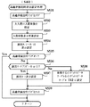
例えば通常遊技状態時には、第1の飾り図柄画像となる「0」〜「9」の数字#1を示す画像から形成された10種類の図柄が1つの図柄配列を形成し、画像表示装置5の各可変表示部DL、DC、DRにて、図柄が示す番号が大きいものから小さいものへ、あるいは、図柄が示す番号が小さいものから大きいものへと、切替表示やスクロール表示が行われるとともに、予め定められた第1のアニメ変動態様によるアニメーション表示が行われる。図2(A)は数字#1に含まれて「7」の数字を示す図柄のアニメ変動態様の一例を示している。また、図2(B)は数字#1に含まれて「8」の数字を示すアニメ変動態様の一例を示している。数字#1は、アニメ変動のインデックス番号が「1」〜「5」の範囲で切り替えられることにより、その表示態様である模様をアニメーションのように変化させるアニメーション表示が可能となっている。   For example, in the normal game state, 10 types of symbols formed from the image indicating the number # 1 of “0” to “9” that are the first decorative symbol images form one symbol array, and the image display device 5 In each of the variable display portions DL, DC, DR, switching display and scroll display are performed in advance from the largest number indicated by the symbol to the smallest number, or from the smallest number indicated by the symbol to the largest number. Animation display according to the determined first animation variation mode is performed. FIG. 2A shows an example of the animation variation mode of the symbol indicating the number “7” included in the number # 1. FIG. 2B shows an example of an animation variation mode included in the number # 1 and indicating the number “8”. The number # 1 can be displayed in an animation in which the pattern that is the display mode is changed like an animation by switching the animation variation index number in the range of “1” to “5”.

また、例えば高確率状態時には、第1の飾り図柄画像とはアニメ変動態様が異なり第2の飾り図柄画像となる「0」〜「9」の数字#2を示す画像から形成された10種類の図柄が1つの図柄配列を形成し、画像表示装置5の各可変表示部DL、DC、DRにて、図柄が示す番号が大きいものから小さいものへ、あるいは、図柄が示す番号が小さいものから大きいものへと、切替表示やスクロール表示が行われるとともに、第1のアニメ変動態様とは異なる第2のアニメ変動態様によるアニメーション表示が行われる。図2(C)は数字#2に含まれて「7」の数字を示す図柄のアニメ変動態様の一例を示している。また、図2(D)は数字#2に含まれて「8」の数字を示すアニメ変動態様の一例を示している。数字#2は、アニメ変動のインデックス番号が「1」〜「5」の範囲で切り替えられることにより、その表示態様である模様をアニメーションのように変化させるアニメーション表示が可能となっている。   Further, for example, in the high probability state, the animation variation mode is different from the first decorative design image, and the 10 types of images formed from the images indicating the numbers # 2 of “0” to “9” that become the second decorative design image. A symbol forms one symbol array, and in each variable display portion DL, DC, DR of the image display device 5, the number indicated by the symbol is changed from the largest to the smallest, or the number indicated by the symbol is increased from the smallest. To the object, switching display and scroll display are performed, and animation display according to a second animation variation mode different from the first animation variation mode is performed. FIG. 2C shows an example of the animation variation mode of the symbol indicating the number “7” included in the number # 2. FIG. 2D shows an example of an animation variation mode that is included in the number # 2 and indicates the number “8”. The number # 2 can be displayed in an animation in which the pattern that is the display mode is changed like an animation by switching the animation fluctuation index number in the range of “1” to “5”.

普通可変入賞球装置6は、例えばソレノイド50(図4)によって垂直位置と傾動位置との間で可動制御される一対の可動翼片を有するチューリップ型役物(普通電動役物)を備えて構成される。この可動翼片が垂直位置にあるときには普通可変入賞球装置6に設けられた始動入賞口が通常開放される一方で、可動翼片が傾動位置にあるときには始動入賞口が拡大開放される。普通図柄表示装置20による普通図柄の可変表示(普通図ゲーム)で表示結果が当りとなったときに、普通可変入賞球装置6では電動チューリップの可動翼片を所定時間が経過するまで傾動位置に制御することで始動入賞口を拡大開放し、可動翼片を垂直位置とすることにより始動入賞口を通常開放したときに比べて遊技球が入賞しやすくなる。普通可変入賞球装置6に入賞した遊技球は、始動入賞口スイッチ40によって検出される。   The normal variable winning ball apparatus 6 includes a tulip-type accessory (ordinary electric accessory) having a pair of movable wing pieces that are controlled to move between a vertical position and a tilt position by a solenoid 50 (FIG. 4), for example. Is done. When the movable wing piece is in the vertical position, the starting winning opening provided in the normally variable winning ball apparatus 6 is normally opened, while when the movable wing piece is in the tilting position, the starting winning opening is enlarged and opened. When the display result is a hit in the normal symbol variable display (ordinary symbol game) by the normal symbol display device 20, the normal variable winning ball device 6 moves the movable wing piece of the electric tulip to the tilted position until a predetermined time elapses. By controlling, the start winning opening is enlarged and opened, and the movable wing piece is set in the vertical position, so that the game ball is easier to win than when the starting winning opening is normally opened. The game ball that has won the normal variable winning ball device 6 is detected by the start winning port switch 40.

特別可変入賞球装置7では、例えばソレノイド51(図4)を駆動することによる開閉板21の開閉動作によって、入賞領域となる大入賞口が開成状態と閉成状態とで切り替えられる。開閉板21は、例えばパチンコ遊技機1の電源投入後に大当り遊技状態が発生する以前までのような通常時には、大入賞口を閉成し、遊技者にとって不利な第1の状態にする。他方、特別図柄表示装置4による特図ゲームでの可変表示結果などに基づいて大当り遊技状態となったときに、ソレノイド51によって大入賞口を所定期間あるいは所定個数の入賞球が入賞するまでの期間において開成し、第1の状態(閉成状態)から遊技者にとって有利な第2の状態(開放状態)にする。その後、大入賞口を第1の状態(閉成状態)に戻す。すなわち、特別可変入賞球装置7に設けられた入賞領域となる大入賞口は、開成状態において遊技球を特別可変入賞球装置7内に進入可能とし、閉成状態において遊技球を特別可変入賞球装置7内に進入不能とする可変進入口である。   In the special variable winning ball apparatus 7, for example, the opening / closing operation of the opening / closing plate 21 by driving the solenoid 51 (FIG. 4) switches the large winning opening as a winning area between the open state and the closed state. The opening / closing plate 21 closes the big prize opening at a normal time, for example, before the big hit gaming state occurs after the power of the pachinko gaming machine 1 is turned on, and is in a first state which is disadvantageous for the player. On the other hand, when a big hit gaming state is reached based on a variable display result in a special symbol game by the special symbol display device 4, a period until a predetermined winning slot or a predetermined number of winning balls are won by the solenoid 51 The first state (closed state) is changed to the second state (open state) advantageous to the player. Thereafter, the special winning opening is returned to the first state (closed state). That is, the large winning opening which is a winning area provided in the special variable winning ball device 7 allows the game ball to enter the special variable winning ball device 7 in the opened state, and the game ball to the special variable winning ball in the closed state. This is a variable advance entrance that prevents entry into the device 7.

図3(A)は、特別可変入賞球装置7の一構成例を拡大して示している。特別可変入賞球装置7には、開閉板21によって開閉される可変進入口である大入賞口の下方に転動板22が設けられている。図3(B)は、転動板22の上面図である。図3(C)は、図3(A)及び(B)に示す破線A−A’における転動板22の断面図である。   FIG. 3A shows an enlarged configuration example of the special variable winning ball apparatus 7. In the special variable winning ball apparatus 7, a rolling plate 22 is provided below a large winning opening that is a variable entrance that is opened and closed by an opening / closing plate 21. FIG. 3B is a top view of the rolling plate 22. FIG. 3C is a cross-sectional view of the rolling plate 22 taken along a broken line A-A ′ shown in FIGS.

転動板22は、転動板24A、24Bに接続されており、転動板22の上面には、大入賞口から特別可変入賞球装置7内に進入した遊技球を転動板24Aへと誘導する誘導路22Aと、転動板24Bへと誘導する誘導路22Bとが設けられている。誘導路22Aは、転動板22から遊技球が落下することがないように、リブ23Aによって特別可変入賞球装置7の壁面と仕切られている。また、誘導路22Aと誘導路22Bとの間には、リブ23Bが形成されており、大入賞口から特別可変入賞球装置7内に進入した遊技球が誘導路22Aと誘導路22Bのいずれかに振り分けられるようになっている。なお、リブ23Bは遊技球が乗り越え可能な程度に形成して、誘導路22A上の遊技球が誘導路22Bへと、あるいは、誘導路22B上の遊技球が誘導路22Aへと、移動することができるようにしてもよい。誘導路22Bの端部には、リブ23Aやリブ23Bの形成方向に沿ってリブ23Cが形成されている。リブ23Cは誘導路22B上の遊技球が乗り越え可能な程度に形成されており、誘導路22B上でリブ23Cを乗り越えた遊技球は、転動板22から特別可変入賞球装置7内の下方に形成された空間を落下した後、排出口32から特別可変入賞球装置7の外部へと排出される。   The rolling plate 22 is connected to the rolling plates 24A and 24B. On the upper surface of the rolling plate 22, game balls that have entered the special variable winning ball device 7 from the big prize opening are transferred to the rolling plate 24A. A guiding path 22A for guiding and a guiding path 22B for guiding to the rolling plate 24B are provided. The guide path 22A is partitioned from the wall surface of the special variable winning ball apparatus 7 by the rib 23A so that the game ball does not fall from the rolling plate 22. Also, a rib 23B is formed between the guide path 22A and the guide path 22B, and a game ball that has entered the special variable winning ball apparatus 7 from the big prize opening is either the guide path 22A or the guide path 22B. Can be distributed to. The ribs 23B are formed so that the game balls can get over, and the game balls on the guide path 22A move to the guide paths 22B, or the game balls on the guide path 22B move to the guide paths 22A. You may be able to. A rib 23C is formed at the end of the guide path 22B along the forming direction of the rib 23A and the rib 23B. The ribs 23C are formed so that the game balls on the guide path 22B can get over. After dropping the formed space, it is discharged from the discharge port 32 to the outside of the special variable winning ball apparatus 7.

大入賞口から特別可変入賞球装置7内に進入した遊技球のうちで、誘導路22A上を転動する遊技球は、例えば光センサなどを備えて構成された高確率通路検出スイッチ41Aによって検出される。高確率通路検出スイッチ41Aによって誘導路22A上の遊技球が検出されたときには、遊技制御カウンタ設定部125(図10)に設けられた大入賞口入賞球カウンタにおけるカウント値が、例えば1加算されるなどして更新される。この後、誘導路22A上の遊技球は、例えば図3(B)にて矢印a11で示すように、転動板24Aへと誘導される。すなわち、誘導路22Aには、高確率通路検出スイッチ41Aによって検出された遊技球を転動板24Aへと転動させることが可能な傾斜が形成されている。   Of the game balls that have entered the special variable winning ball device 7 from the big prize opening, the game ball that rolls on the guide path 22A is detected by, for example, a high probability path detection switch 41A configured with an optical sensor or the like. Is done. When a game ball on the guidance path 22A is detected by the high probability path detection switch 41A, for example, 1 is added to the count value in the big prize opening winning ball counter provided in the game control counter setting unit 125 (FIG. 10). Etc. are updated. Thereafter, the game ball on the guide path 22A is guided to the rolling plate 24A as indicated by an arrow a11 in FIG. 3B, for example. That is, the guide path 22A is formed with an inclination that allows the game ball detected by the high probability path detection switch 41A to roll to the rolling plate 24A.

大入賞口から特別可変入賞装置7内に進入した遊技球のうちで、誘導路22B上を転動する遊技球は、例えば光センサなどを備えて構成された低確率通路検出スイッチ41Bによって検出される。低確率通路検出スイッチ41Bによって誘導路22B上の遊技球が検出されたときには、遊技制御カウンタ設定部125(図10)に設けられた大入賞口入賞球カウンタにおけるカウント値が、例えば1加算されるなどして更新される。   Of the game balls that have entered the special variable winning device 7 from the big prize opening, the game ball that rolls on the guide path 22B is detected by, for example, a low-probability passage detection switch 41B configured with an optical sensor or the like. The When a game ball on the guidance path 22B is detected by the low probability path detection switch 41B, for example, 1 is added to the count value in the big prize winning ball counter provided in the game control counter setting unit 125 (FIG. 10). Etc. are updated.

転動板22には、誘導路22Bにて上下に進出及び退避が可能な可動部材25が設けられている。例えば、可動部材25は、所定のリンク機構を介してソレノイド52(図4)に連結されており、ソレノイド52が駆動されたときには、その駆動力により誘導路22B上に進出する。可動部材25が下方に退避しているときには、誘導路22B上の遊技球を、例えば図3(B)にて矢印a21で示すように、転動板24Bへと誘導することができる。すなわち、誘導路22Bには、低確率通路検出スイッチ41Bによって検出された遊技球を転動板24Bへと転動させることが可能な傾斜が形成されている。これに対して、可動部材25が上方に進出しているときには、誘導路22B上の遊技球を、例えば図3(B)にて矢印a22で示すように、転動板22上から落下させて排出口32から特別可変入賞球装置7の外部へと排出させる。また、可動部材25が下方に退避しているときであっても、誘導路22B上の遊技球がリブ23Cを乗り越えて転動板22上から落下することがある。   The rolling plate 22 is provided with a movable member 25 that can be moved up and down by a guide path 22B. For example, the movable member 25 is connected to a solenoid 52 (FIG. 4) via a predetermined link mechanism, and when the solenoid 52 is driven, it advances onto the guide path 22B by the driving force. When the movable member 25 is retracted downward, the game ball on the guide path 22B can be guided to the rolling plate 24B as indicated by an arrow a21 in FIG. 3B, for example. That is, the guide path 22B is formed with an inclination that allows the game ball detected by the low probability path detection switch 41B to roll to the rolling plate 24B. On the other hand, when the movable member 25 advances upward, the game ball on the guide path 22B is dropped from the rolling plate 22 as indicated by an arrow a22 in FIG. 3B, for example. The special variable winning ball apparatus 7 is discharged from the discharge port 32 to the outside. Even when the movable member 25 is retracted downward, the game ball on the guide path 22B may get over the rib 23C and fall from the rolling plate 22.

転動板24Aは、例えば中心部が窪んだすり鉢状の形状を有し、誘導路22Aによって転動板24A上に誘導された遊技球が転動板24A上を旋回しながら転動板24Aの中心部に向かって転動可能となっている。また、転動板24Aには、例えば遊技球が通過可能な2つの開口部として、通常進入口30Aと特定進入口30Bとが形成されている。2つの開口部のうちの特定進入口30Bは特定領域となり、特定進入口30Bに進入した遊技球が特定領域検出スイッチ42A(図4)によって検出される。   The rolling plate 24A has, for example, a mortar shape with a depressed central portion, and the game ball guided onto the rolling plate 24A by the guide path 22A turns on the rolling plate 24A while the rolling plate 24A Rollable toward the center. The rolling plate 24A is formed with a normal entrance 30A and a specific entrance 30B, for example, as two openings through which a game ball can pass. Of the two openings, the specific entrance 30B becomes a specific area, and a game ball that has entered the specific entrance 30B is detected by the specific area detection switch 42A (FIG. 4).

転動板24Bは、例えば中央部が窪んだすり鉢状の形状を有し、誘導路22Bによって転動板24B上に誘導された遊技球が転動板24B上を旋回しながら転動板24Bの中心部に向かって転動可能となっている。また、転動板24Bには、例えば遊技球が通過可能な4つの開口部として、通常進入口31A、31B、31Dと特定進入口31Cとが形成されている。4つの開口部のうちの特定進入口31Cは特定領域となり、特定進入口31Cに進入した遊技球が特定領域検出スイッチ42B(図4)によって検出される。   The rolling plate 24B has, for example, a mortar shape with a depressed central portion, and a game ball guided onto the rolling plate 24B by the guide path 22B swivels on the rolling plate 24B while the rolling plate 24B Rollable toward the center. The rolling plate 24B is formed with normal advance entrances 31A, 31B, 31D and a specific advance entrance 31C as four openings through which a game ball can pass, for example. Of the four openings, the specific entrance 31C becomes a specific area, and the game ball that has entered the specific entrance 31C is detected by the specific area detection switch 42B (FIG. 4).

特定領域検出スイッチ42A、42Bのいずれかによって特定進入口30Bと特定進入口31Cのいずれかに進入した遊技球が検出されたときには、遊技制御カウンタ設定部125(図10)に設けられた特定領域進入球カウンタにおけるカウント値が、例えば1加算されるなどして更新される。そして、この実施の形態では、大当り遊技状態において開閉板21により可変進入口である大入賞口が開成される最初のラウンド(例えば第1ラウンド)が開始されてから、最後のラウンド(例えば第15ラウンド)が終了して開閉板21により大入賞口が閉成された後、所定の有効期間が経過するまでの間に、特定領域である特定進入口30Bと特定進入口31Cに進入した遊技球の合計個数が所定の確変突入基準値(例えば「15」)に達したときに、所定条件が成立したものとして、その大当り遊技状態が終了した後に高確率状態とする旨の決定がなされる。例えば、特定進入口30Bと特定進入口31Cのいずれかに遊技球が進入して特定領域検出スイッチ42A、42Bのいずれかによって検出されるごとに、特定領域への進入球数が1ずつ加算され、大当り遊技状態が開始されてから終了するまでに、その進入球数が確変突入基準値に達すると、大当り遊技状態の終了後に高確率状態とするための条件が成立する。   When a game ball that has entered either the specific entrance 30B or the specific entrance 31C is detected by any of the specific area detection switches 42A and 42B, the specific area provided in the game control counter setting unit 125 (FIG. 10) The count value in the approach ball counter is updated by adding 1 for example. In this embodiment, in the big hit gaming state, the first round (for example, the first round) in which the big winning opening which is a variable advance entrance is opened by the opening / closing plate 21 is started, and then the last round (for example, the fifteenth round). The game balls that have entered the specific entrance 30B and the specific entrance 31C, which are the specific areas, after the round is finished and the prize opening is closed by the opening and closing plate 21 until the predetermined validity period elapses. When the total number reaches the predetermined probability change entry reference value (for example, “15”), it is determined that the predetermined condition is satisfied, and the high probability state is determined after the big hit gaming state ends. For example, every time a game ball enters one of the specific entrance 30B and the specific entrance 31C and is detected by any of the specific area detection switches 42A and 42B, the number of balls entering the specific area is incremented by one. When the number of approaching balls reaches the probability variation entry reference value from the start to the end of the big hit gaming state, the condition for setting the high probability state after the big hit gaming state is satisfied.

ここで、転動板24Aには2つの開口部として通常進入口30Aと特定進入口30Bとが形成され、そのうちの1つの開口部である特定進入口30Bが特定領域となっている。これに対して、転動板24Bには4つの開口部として通常進入口31A、31B、31Dと特定進入口31Cとが形成され、そのうちの1つの開口部である特定進入口31Cが特定領域となっている。このため、遊技球が特定領域に進入する割合は、転動板24Aの方が転動板24Bに比べて高くなっている。そして、転動板24A上を転動する遊技球が特定領域としての特定進入口30Bに進入したときには特定領域への進入球数が加算されて高確率状態となるための条件成立に寄与する一方で、通常進入口30Aに進入したときには特定領域への進入球数が加算されずに高確率状態となるための条件成立に寄与しない。このように、転動板24A上にて遊技球が転動する領域は、高確率状態とするための条件を成立させるか否かを決定するための抽選領域となっている。加えて、転動板24B上を転動する遊技球が特定領域としての特定進入口31Cに進入したときには特定領域への進入球数が加算されて高確率状態となるための条件成立に寄与する一方で、通常進入口31A、31B、31Dのいずれかに進入したときには特定領域への進入球数が加算されずに高確率状態となるための条件成立に寄与しない。このように、転動板24B上にて遊技球が転動する領域も、高確率状態が成立するための条件を成立させるか否かを決定するための抽選領域となっている。   Here, in the rolling plate 24A, a normal entrance 30A and a specific entrance 30B are formed as two openings, and a specific entrance 30B which is one of the openings is a specific region. In contrast, the rolling plate 24B is formed with normal entrances 31A, 31B, 31D and a specific entrance 31C as four openings, and the specific entrance 31C, which is one of the openings, is defined as a specific region. It has become. For this reason, the rate at which the game balls enter the specific area is higher in the rolling plate 24A than in the rolling plate 24B. When a game ball that rolls on the rolling plate 24A enters the specific entrance 30B as the specific area, the number of balls entering the specific area is added to contribute to the establishment of a condition for achieving a high probability state. Thus, when entering the normal entrance 30A, the number of approaching balls to the specific area is not added and does not contribute to the establishment of a condition for achieving a high probability state. Thus, the area where the game ball rolls on the rolling plate 24A is a lottery area for determining whether or not a condition for achieving a high probability state is satisfied. In addition, when a game ball rolling on the rolling plate 24B enters the specific entrance 31C as the specific area, the number of balls entering the specific area is added to contribute to the establishment of a condition for achieving a high probability state. On the other hand, when entering any of the normal entrances 31A, 31B, 31D, the number of balls entering the specific area is not added and does not contribute to the establishment of a condition for achieving a high probability state. Thus, the area where the game ball rolls on the rolling plate 24B is also a lottery area for determining whether or not a condition for establishing a high probability state is established.

また、転動板22に形成された誘導路22Aが転動板24Aに接続されている一方で、転動板22に形成された誘導路22Bが転動板24Bに接続されている。そのため、大入賞口から特別可変入賞球装置7内に進入して誘導路22A上を転動した遊技球のうちで、特定領域である特定進入口30Bに進入することで高確率状態となるための条件成立に寄与する遊技球の割合は、大入賞口から特別可変入賞球装置7に進入して誘導路22B上を転動した遊技球のうちで、特定領域である特定進入口31Cに進入することで高確率状態となるための条件成立に寄与する遊技球の割合に比べて、高くなる。すなわち、誘導路22Aは、誘導路22Bに比べて大当り遊技状態の終了後に高確率状態となるための条件成立に寄与する遊技球の割合が高い高確率通路であり、誘導路22Bに比べて高い割合で高確率状態となるための条件が成立する。これに対して、誘導路22Bは、誘導路22Aに比べて大当り遊技状態の終了後に高確率状態となるための条件成立に寄与する遊技球の割合が低い低確率通路であり、誘導路22Aに比べて低い割合で高確率状態となるための条件が成立する。   A guide path 22A formed on the rolling plate 22 is connected to the rolling plate 24A, while a guide path 22B formed on the rolling plate 22 is connected to the rolling plate 24B. For this reason, the game balls that have entered the special variable winning ball apparatus 7 from the large winning opening and rolled on the guide path 22A enter the specific entrance 30B, which is a specific area, so that a high probability state is obtained. The ratio of the game balls that contribute to the establishment of the condition is that the game balls that have entered the special variable winning ball device 7 from the big prize opening and rolled on the guide path 22B enter the specific entrance 31C that is a specific area. By doing so, it becomes higher than the proportion of game balls that contribute to the establishment of a condition for achieving a high probability state. That is, the guiding path 22A is a high-probability path that has a higher proportion of game balls that contribute to the establishment of a condition for becoming a high-probability state after the end of the big hit gaming state compared to the guiding path 22B, and is higher than the guiding path 22B. A condition for achieving a high probability state at a rate is established. On the other hand, the guide path 22B is a low-probability path with a low proportion of game balls contributing to the establishment of a condition for becoming a high-probability state after the end of the big hit gaming state compared to the guide path 22A. A condition for achieving a high probability state at a lower rate is established.

転動板24Aに形成された通常進入口30Aと特定進入口30Bのいずれかに進入した遊技球や、転動板24Bに形成された通常進入口31A、31B、31Dと特定進入口31Cのいずれかに進入した遊技球、及び、排出口32に進入した遊技球は、排出通路33を介して特別可変入賞球装置7の外部へと排出される。この際には、排出通路検出スイッチ44により、特別可変入賞球装置7の外部へと排出される遊技球の検出が行われる。また、特別可変入賞球装置7の内部には、所定のV入賞領域が設けられており、V入賞領域に入賞した遊技球は、V入賞検出スイッチ43(図4)によって検出される。   A game ball that has entered one of the normal entrance 30A and the specific entrance 30B formed in the rolling plate 24A, or any of the normal entrances 31A, 31B, 31D and the specific entrance 31C formed in the rolling plate 24B The game balls that have entered the crab and the game balls that have entered the discharge port 32 are discharged to the outside of the special variable winning ball apparatus 7 through the discharge passage 33. At this time, a game ball discharged to the outside of the special variable winning ball apparatus 7 is detected by the discharge passage detection switch 44. Further, a predetermined V winning area is provided inside the special variable winning ball apparatus 7, and a game ball that has won the V winning area is detected by the V winning detection switch 43 (FIG. 4).

その他、遊技盤2の表面には、上記の構成以外にも、ランプを内蔵した風車、アウト口等が設けられている。遊技機用枠3の左右上部位置には、効果音等を再生出力するためのスピーカ8L、8Rが設けられており、さらに遊技領域周辺部には、遊技効果ランプ9が設けられている。パチンコ遊技機1の遊技領域における各構造物(例えば普通可変入賞球装置6や特別可変入賞球装置7等)の周囲には装飾用LEDが設置されていてもよい。   In addition to the above configuration, the surface of the game board 2 is provided with a windmill with a built-in lamp, an outlet, and the like. Speakers 8L and 8R for reproducing and outputting sound effects and the like are provided at the left and right upper positions of the gaming machine frame 3, and a game effect lamp 9 is provided at the periphery of the game area. A decorative LED may be provided around each structure (for example, the normal variable winning ball device 6 or the special variable winning ball device 7) in the game area of the pachinko gaming machine 1.

パチンコ遊技機1には、例えば図4に示すような主基板11や演出制御基板12といった、各種の制御基板が搭載されている。また、パチンコ遊技機1には、主基板11と演出制御基板12との間で伝送される各種の制御信号を中継するための信号中継基板13なども搭載されている。主基板11と演出制御基板12は、パチンコ遊技機1の背面にて適所に配置され、両基板の間に、例えば演出制御信号の信号線やストローブ信号を送受信するための演出制御INT信号の信号線などが配線されている。なお、演出制御基板12は、表示制御基板や音声制御基板、ランプ制御基板といった複数の独立した基板によって構成されてもよいし、これらをまとめた1つの基板として構成されてもよい。その他、パチンコ遊技機1の背面には、払出制御基板、情報端子基板などといった、各種の制御基板が配置されている。   Various control boards such as a main board 11 and an effect control board 12 shown in FIG. The pachinko gaming machine 1 is also equipped with a signal relay board 13 for relaying various control signals transmitted between the main board 11 and the effect control board 12. The main board 11 and the effect control board 12 are arranged at appropriate positions on the back of the pachinko gaming machine 1, and for example, an effect control INT signal signal for transmitting / receiving an effect control signal line or a strobe signal between the two boards. Wires are wired. The production control board 12 may be configured by a plurality of independent boards such as a display control board, a sound control board, and a lamp control board, or may be configured as a single board in which these are combined. In addition, various control boards such as a payout control board and an information terminal board are arranged on the back of the pachinko gaming machine 1.

主基板11は、メイン側の制御基板であり、パチンコ遊技機1における遊技の進行を制御するための各種回路が搭載されている。主基板11は、主として、特図ゲームにおいて用いる乱数の設定機能、所定位置に配設されたスイッチ等からの信号の入力を行う機能、演出制御基板12などからなるサブ側の制御基板に宛てて、それぞれに指令情報の一例となる制御コマンドを制御信号として出力して送信する機能、ホールの管理コンピュータに対して各種情報を出力する機能などを備えている。また、主基板11は、特別図柄表示装置4を構成する各セグメントの点灯/消灯制御を行うことにより特別図柄表示装置4における特別図柄の可変表示を制御する一方で、普通図柄表示装置20の点灯/点滅/発色制御を行うことにより普通図柄表示装置20における普通図柄の可変表示を制御する。   The main board 11 is a main-side control board on which various circuits for controlling the progress of the game in the pachinko gaming machine 1 are mounted. The main board 11 is mainly addressed to a sub-side control board composed of a random number setting function used in a special game, a function of inputting a signal from a switch or the like disposed at a predetermined position, and an effect control board 12. Each has a function of outputting and transmitting a control command as an example of command information as a control signal, a function of outputting various information to a hall management computer, and the like. Further, the main board 11 controls the variable symbol display in the special symbol display device 4 by controlling the lighting / extinguishing of each segment constituting the special symbol display device 4, while the normal symbol display device 20 is turned on. The variable symbol display on the normal symbol display device 20 is controlled by performing blinking / coloring control.

主基板11から演出制御基板12に向けて出力される制御信号は、信号中継基板13によって中継される。主基板11には、例えば信号中継基板13対応の主基板側コネクタが設けられ、主基板側コネクタと遊技制御用マイクロコンピュータとの間には、出力バッファ回路が接続されている。出力バッファ回路は、主基板11から信号中継基板13を介して演出制御基板12へ向かう方向にのみ信号を通過させることができ、信号中継基板13から主基板11への信号の入力を阻止する。従って、演出制御基板12や信号中継基板13の側から主基板11側に信号が伝わる余地はない。   A control signal output from the main board 11 toward the effect control board 12 is relayed by the signal relay board 13. The main board 11 is provided with a main board side connector corresponding to the signal relay board 13, for example, and an output buffer circuit is connected between the main board side connector and the game control microcomputer. The output buffer circuit can pass a signal only in the direction from the main board 11 to the effect control board 12 via the signal relay board 13 and prevents the signal from being input from the signal relay board 13 to the main board 11. Therefore, there is no room for signals to be transmitted from the production control board 12 or the signal relay board 13 side to the main board 11 side.

信号中継基板13には、例えば主基板11から演出制御基板12に対して出力される制御信号を伝達するための配線毎に、伝送方向規制回路が設けられている。各伝送方向規制回路は、主基板11対応の主基板用コネクタにアノードが接続されるとともに演出制御基板12対応の演出制御基板用コネクタにカソードが接続されたダイオードと、一端がダイオードのカソードに接続されるとともに他端がグランド(GND)接続された抵抗とから構成されている。この構成により、各伝送方向規制回路は、演出制御基板12から信号中継基板13への信号の入力を阻止して、主基板11から演出制御基板12へ向かう方向にのみ信号を通過させることができる。従って、演出制御基板12の側から主基板11側に信号が伝わる余地はない。なお、主基板への不正な信号の入力を防ぐために、主基板とサブ基板との間に主基板からサブ基板への信号の出力のみを規制する一方向データ転送手段を設けたものは既に提案されている(例えば、特開平8−224339号公報などを参照)。しかしながら、主基板と一方向データ転送手段との間には主基板への信号入力を規制するものがないため、一方向データ転送手段に改変を加えることで主基板に不正な信号を入力させることが可能であった。この実施の形態では、信号中継基板13において制御信号を伝送するための配線毎に伝送方向規制回路を設けるとともに、主基板11にて遊技制御用マイクロコンピュータ100と主基板側コネクタの間に出力バッファ回路を設けることで、外部から主基板11への不正な信号の入力を、より確実に防止することができる。   The signal relay board 13 is provided with a transmission direction regulating circuit for each wiring for transmitting a control signal output from the main board 11 to the effect control board 12, for example. Each transmission direction regulating circuit includes a diode having an anode connected to the main board connector corresponding to the main board 11 and a cathode connected to the presentation control board connector corresponding to the presentation control board 12, and one end connected to the cathode of the diode. And a resistor having the other end connected to the ground (GND). With this configuration, each transmission direction regulating circuit can prevent signals from being input from the effect control board 12 to the signal relay board 13 and pass signals only in the direction from the main board 11 to the effect control board 12. . Therefore, there is no room for signals to be transmitted from the production control board 12 side to the main board 11 side. In order to prevent unauthorized input of signals to the main board, a one-way data transfer means that restricts only the signal output from the main board to the sub board between the main board and the sub board has already been proposed. (See, for example, JP-A-8-224339). However, since there is nothing that restricts signal input to the main board between the main board and the one-way data transfer means, it is possible to input illegal signals to the main board by modifying the one-way data transfer means. Was possible. In this embodiment, a transmission direction regulating circuit is provided for each wiring for transmitting a control signal in the signal relay board 13, and an output buffer is provided between the game control microcomputer 100 and the main board side connector on the main board 11. By providing the circuit, it is possible to more reliably prevent an illegal signal input from the outside to the main board 11.

このような信号中継基板13を介して主基板11から演出制御基板12に対して送信される制御コマンドは、例えば電気信号として伝送される演出制御コマンドである。演出制御コマンドには、例えば画像表示装置5における画像表示動作を制御するために用いられる表示制御コマンドや、スピーカ8R、8Lからの音声出力を制御するために用いられる音声制御コマンド、遊技効果ランプ9や装飾用LEDの点灯動作などを制御するために用いられるランプ制御コマンドが含まれている。図5は、この実施の形態で用いられる表示制御コマンドの内容の一例を示す説明図である。表示制御コマンドは、例えば2バイト構成であり、1バイト目はMODE(コマンドの分類)を示し、2バイト目はEXT(コマンドの種類)を表す。MODEデータの先頭ビット(ビット7)は必ず「1」とされ、EXTデータの先頭ビットは「0」とされる。なお、図5に示されたコマンド形態は一例であって、他のコマンド形態を用いてもよい。また、この例では、制御コマンドが2つの制御信号で構成されることになるが、制御コマンドを構成する制御信号数は、1であってもよいし、3以上の複数であってもよい。   The control command transmitted from the main board 11 to the effect control board 12 via the signal relay board 13 is an effect control command transmitted as an electric signal, for example. The effect control command includes, for example, a display control command used for controlling an image display operation in the image display device 5, a voice control command used for controlling sound output from the speakers 8R and 8L, and a game effect lamp 9. And a lamp control command used for controlling the lighting operation of the decorative LED and the like. FIG. 5 is an explanatory diagram showing an example of the contents of the display control command used in this embodiment. The display control command has, for example, a 2-byte structure, and the first byte indicates MODE (command classification), and the second byte indicates EXT (command type). The first bit (bit 7) of the MODE data is always “1”, and the first bit of the EXT data is “0”. Note that the command form shown in FIG. 5 is an example, and other command forms may be used. In this example, the control command is composed of two control signals. However, the number of control signals constituting the control command may be one or a plurality of three or more.

この実施の形態では、表示制御コマンドとして、可変表示開始コマンド、表示結果通知コマンド、可変表示終了コマンド、大当り開始コマンド、ラウンド数通知コマンド、大当り終了コマンド、高確率通路検出コマンド、低確率通路検出コマンド、特定領域進入検出コマンド、排出済コマンドなどが、予め用意されている。   In this embodiment, as display control commands, variable display start command, display result notification command, variable display end command, jackpot start command, round number notification command, jackpot end command, high probability path detection command, low probability path detection command A specific area entry detection command, a discharged command, and the like are prepared in advance.

図5に示す例において、コマンド8000H〜80XXHは、特別図柄表示装置4による特図ゲームで特別図柄の可変表示を開始するときに送信される可変表示開始コマンドである。なお、XXHは不特定の16進数であることを示し、表示制御コマンドによる指示内容に応じて任意に設定される値であればよい。可変表示開始コマンドは、例えば特別図柄表示装置4による特別図柄の可変表示が開始されてから確定特別図柄が停止表示されるまでの時間である特別図柄の可変表示時間や、特図ゲームにおける可変表示結果が大当りとなるかハズレとなるかといった可変表示結果の種類、さらには、飾り図柄の可変表示態様をリーチとしてからハズレとなるリーチハズレとするか、リーチとすることなくハズレとなる通常ハズレとするか、などを示すEXTデータを含んでいる。   In the example shown in FIG. 5, commands 8000H to 80XXH are variable display start commands transmitted when variable display of special symbols is started in the special symbol game by the special symbol display device 4. XXH indicates an unspecified hexadecimal number, and may be a value arbitrarily set according to the instruction content by the display control command. The variable display start command is, for example, the variable display time of a special symbol, which is the time from the start of variable display of a special symbol by the special symbol display device 4 to the stop display of a fixed special symbol, or variable display in a special game. The type of variable display result, such as whether the result will be a big hit or a loss, and further, the variable display mode of the decorative design will be a reach loss that will be lost after reaching, or a normal loss that will be lost without reaching EXT data indicating such as.

ここで、リーチとは、画像表示装置5にて導出表示した飾り図柄が大当り組合せの一部を構成しているときに未だ導出表示していない飾り図柄(リーチ変動図柄という)については変動表示が行われている表示態様、あるいは、全て又は一部の飾り図柄が大当り図柄の全て又は一部を構成しながら同期して変動表示している表示態様のことである。具体的には、予め定められた組合せ有効ライン上の一部の可変表示部に予め定められた大当り組合せを構成する図柄を停止表示しているときに未だ停止表示していない組合せ有効ライン上の可変表示部において変動表示が行われている表示態様(例えば、表示領域に設けられた「左」、「中」、「右」の可変表示部DL、DC、DRのうち「左」、「右」の可変表示部DL、DRには大当り図柄の一部となる(例えば「7」)が停止表示されている状態で「中」の可変表示部DCは未だ変動表示が行われている表示態様)、あるいは、有効ライン上の可変表示部の全て又は一部の飾り図柄が大当り図柄の全て又は一部を構成しながら同期して変動表示している表示態様(例えば、表示領域に設けられた「左」、「中」、「右」の可変表示部DL、DC、DRの全てで変動表示が行われてどの状態が表示されても同一の飾り図柄が揃っている態様で変動表示が行われている表示態様)である。また、リーチの際に、通常と異なる演出がランプや音などで行われることがある。この演出をリーチ演出という。また、リーチの際に、画像表示装置5にてキャラクタ(人物等を模した演出表示であり、飾り図柄とは異なるもの)を表示させたり、背景の表示態様を変化させたり、飾り図柄の変動表示態様を変化させたりすることがある。このキャラクタの表示や背景の表示態様、飾り図柄の変動態様の変化を、リーチ演出表示という。   Here, the reach means that a decorative display (referred to as a reach variation pattern) that has not yet been derived and displayed when the decorative pattern derived and displayed by the image display device 5 forms a part of the jackpot combination is a variable display. It is a display mode that is being performed, or a display mode in which all or some of the decorative symbols are synchronously displayed while constituting all or part of the jackpot symbol. Specifically, on the combination effective line that has not been stopped yet when the symbols constituting the predetermined jackpot combination are stopped and displayed on some of the variable display portions on the predetermined combination effective line. Display mode in which variable display is performed in the variable display section (for example, “left”, “right” among the “left”, “middle”, “right” variable display sections DL, DC, DR provided in the display area The variable display portions DL and DR of "" are displayed in a state in which the variable display portion DC of "medium" is still being displayed in a state where a part of the jackpot symbol (for example, "7") is stopped and displayed. ), Or a display mode in which all or part of the decorative symbols on the active line are synchronously displayed while constituting all or part of the jackpot symbol (for example, provided in the display area) “Left”, “Middle”, “Right” variable display D A DC, all in a display mode change displayed in a mode Whichever state is displayed is performed variably displayed have all the same decorative pattern is being carried out in DR). Also, during the reach, unusual effects may be performed with lamps or sounds. This production is called reach production. Further, during the reach, the image display device 5 displays a character (an effect display imitating a person or the like, which is different from the decorative design), changes the display mode of the background, or changes the decorative design. The display mode may be changed. This change in character display, background display mode, and decorative pattern variation mode is referred to as reach effect display.

コマンド90XXHは、特別図柄表示装置4による特図ゲームにて確定特別図柄として最終的に停止表示(導出表示)される特別図柄の種類を特定可能として演出制御基板12に対して通知する表示結果通知コマンドである。例えば、表示結果通知コマンドは、特別図柄表示装置4による特図ゲームにて確定特別図柄となる図柄の図柄番号を示すEXTデータを含んでいる。この場合、演出制御基板12の側では、表示結果通知コマンドによって通知された確定特別図柄が大当り図柄であるかハズレ図柄であるかを特定することにより、特図ゲームにおける可変表示結果の種類が大当りであるかハズレであるかを識別することができる。あるいは、例えばコマンド9000Hが大当り図柄であることを示し、コマンド9001Hがハズレ図柄であることを示すといったように、演出制御基板12の側において、表示結果通知コマンドによって特図ゲームにおける可変表示結果の種類が大当りであるかハズレであるかを識別することができるように構成してもよい。   The command 90XXH notifies the effect control board 12 that it is possible to specify the type of the special symbol that is finally stopped and displayed (derived display) as the confirmed special symbol in the special symbol game by the special symbol display device 4. It is a command. For example, the display result notification command includes EXT data indicating a symbol number of a symbol that becomes a confirmed special symbol in the special symbol game by the special symbol display device 4. In this case, on the side of the effect control board 12, by specifying whether the confirmed special symbol notified by the display result notification command is a big hit symbol or a lost symbol, the type of variable display result in the special figure game is a big hit. It is possible to identify whether it is or is lost. Or, for example, the command 9000H indicates that it is a big hit symbol, and the command 9001H indicates that it is a lose symbol. It may be configured so that it is possible to identify whether or not is a big hit or a loss.

コマンド9800Hは、特別図柄表示装置4による特図ゲームにおける特別図柄の可変表示を終了するときに送信される可変表示終了コマンドである。すなわち、可変表示終了コマンドは、可変表示開始コマンドにより指定された特別図柄の可変表示時間が経過したことを示している。コマンドA000Hは、特別図柄表示装置4による特図ゲームでの可変表示結果が大当りとなったことにより、大当り遊技状態が開始されることを示す大当り開始コマンドである。例えば、大当り開始コマンドは、パチンコ遊技機1が大当り遊技状態に移行する前に、特図ゲームでの可変表示結果が大当りとなったことを示すファンファーレコマンドである。コマンドA1XXHは、大当り遊技状態において開始されるラウンドの回数を演出制御基板12に対して通知するラウンド数通知コマンドである。コマンドA200Hは、大当り遊技状態が終了することを示す大当り終了コマンドである。   The command 9800H is a variable display end command that is transmitted when the special symbol display device 4 ends the variable symbol special symbol display in the special symbol game. That is, the variable display end command indicates that the variable display time of the special symbol specified by the variable display start command has elapsed. The command A000H is a jackpot start command indicating that the jackpot gaming state is started when the variable display result in the special symbol game by the special symbol display device 4 is a jackpot. For example, the jackpot start command is a fanfare command that indicates that the variable display result in the special figure game is a jackpot before the pachinko gaming machine 1 shifts to the jackpot gaming state. The command A1XXH is a round number notification command for notifying the effect control board 12 of the number of rounds started in the big hit gaming state. Command A200H is a jackpot end command indicating that the jackpot gaming state is ended.

コマンドB0XXHは、大入賞口から特別可変入賞球装置7内に進入した遊技球が高確率通路となる誘導路22A上を通過したときに、その遊技球が高確率通路検出スイッチ41Aによって検出されたことを示す高確率通路検出コマンドである。高確率通路検出コマンドは、遊技制御カウンタ設定部125(図10)に設けられた大入賞口入賞球カウンタにおけるカウント値を、大入賞口入賞球数として通知するためのEXTデータを含んでいる。コマンドB1XXHは、大入賞口から特別可変入賞球装置7内に進入した遊技球が低確率通路となる誘導路22B上を通過したときに、その遊技球が低確率通路検出スイッチ41Bによって検出されたことを示す低確率通路検出コマンドである。低確率通路検出コマンドは、遊技制御カウンタ設定部125(図10)に設けられた大入賞口入賞球カウンタにおけるカウント値を、大入賞口入賞球数として通知するためのEXTデータを含んでいる。   The command B0XXH is detected by the high probability passage detection switch 41A when a game ball that has entered the special variable winning ball device 7 from the big prize opening passes through the guide path 22A that is a high probability passage. This is a high-probability path detection command indicating this. The high-probability passage detection command includes EXT data for notifying the count value of the winning prize winning ball counter provided in the game control counter setting unit 125 (FIG. 10) as the number of winning prize winning balls. The command B1XXH is detected by the low-probability passage detection switch 41B when the game ball that has entered the special variable winning ball apparatus 7 from the grand prize opening passes through the guide path 22B, which is a low-probability passage. This is a low probability path detection command indicating this. The low-probability passage detection command includes EXT data for notifying the count value of the winning prize winning ball counter provided in the game control counter setting unit 125 (FIG. 10) as the number of winning prize winning balls.

コマンドB2XXHは、大入賞口から特別可変入賞球装置7内に進入した遊技球が、転動板24Aに形成された特定領域となる特定進入口30Bと、転動板24Bに形成された特定領域となる特定進入口31Cのいずれかに進入したときに、その遊技球が特定領域検出スイッチ42A、42Bのいずれかによって検出されたことを示す特定領域進入検出コマンドである。特定領域進入検出コマンドは、遊技制御カウンタ設定部125(図10)に設けられた特定領域進入球カウンタにおけるカウント値を、特定領域進入球数として通知するためのEXTデータを含んでいる。C000Hは、大入賞口から特別可変入賞球装置7内に進入した遊技球が、全て特別可変入賞球装置7の外部へと排出されたことを示す排出済コマンドである。   The command B2XXH is a specific area 30B in which a game ball that has entered the special variable winning ball apparatus 7 from the big prize opening becomes a specific area formed on the rolling plate 24A, and a specific area formed on the rolling plate 24B. This is a specific area entry detection command indicating that the game ball has been detected by any of the specific area detection switches 42A and 42B when entering any one of the specific entrance 31C. The specific area entry detection command includes EXT data for notifying the count value in the specific area entry ball counter provided in the game control counter setting unit 125 (FIG. 10) as the number of specific area entry balls. C000H is a discharged command indicating that all the game balls that have entered the special variable winning ball apparatus 7 from the special winning opening are discharged to the outside of the special variable winning ball apparatus 7.

主基板11は、例えば図4に示すように、遊技制御用マイクロコンピュータ100、スイッチ回路107、ソレノイド回路108などを備えて構成される。遊技制御用マイクロコンピュータ100は、例えば1チップマイクロコンピュータであり、ゲーム制御用のプログラム等を記憶するROM(Read Only Memory)101、ワークメモリとして使用されるRAM(Random Access Memory)102、プログラムに従って制御動作を行うCPU(Central Processing Unit)103、CPU103とは独立して乱数の生成を行う乱数回路104及びI/O(Input/Output)ポート105を含んでいる。   For example, as shown in FIG. 4, the main board 11 includes a game control microcomputer 100, a switch circuit 107, a solenoid circuit 108, and the like. The game control microcomputer 100 is, for example, a one-chip microcomputer, and is controlled according to a ROM (Read Only Memory) 101 for storing a game control program, a RAM (Random Access Memory) 102 used as a work memory, and the program. A CPU (Central Processing Unit) 103 that performs operations, a random number circuit 104 that generates random numbers independently of the CPU 103, and an I / O (Input / Output) port 105 are included.

乱数回路104では、遊技の進行を制御するために用いられる各種の乱数値となる数値データがカウントされる。具体的な一例として、CPU103は、乱数回路104による乱数生成動作の設定を行い、数値データを所定の手順に従って定期的(あるいは不定期)に更新させる。図6は、主基板11の側にてカウントされる乱数値を例示する説明図である。図6に示すように、この実施の形態では、主基板11の側において、大当り判定用の乱数値MR1、リーチ判定用の乱数値MR2、可変表示パターン決定用の乱数値MR3を示す数値データを、カウント可能に制御する。なお、遊技効果を高めるために、これら以外の乱数が用いられてもよい。乱数回路104は、これらの乱数値MR1〜MR3の全部または一部を示す数値データをカウントするものであればよい。CPU103は、乱数回路104とは異なるランダムカウンタを用いて、ソフトウェアによる更新によって、乱数値MR1〜MR3の全部または一部を示す数値データをカウントするようにしてもよい。   The random number circuit 104 counts numerical data as various random values used for controlling the progress of the game. As a specific example, the CPU 103 sets a random number generation operation by the random number circuit 104 and updates the numerical data regularly (or irregularly) according to a predetermined procedure. FIG. 6 is an explanatory diagram illustrating random numbers counted on the main board 11 side. As shown in FIG. 6, in this embodiment, on the main board 11 side, numerical data indicating a random number MR1 for jackpot determination, a random value MR2 for reach determination, and a random value MR3 for variable display pattern determination are stored. Control to count. In addition, in order to improve a game effect, random numbers other than these may be used. The random number circuit 104 only needs to count numerical data indicating all or part of these random number values MR1 to MR3. The CPU 103 may count numerical data indicating all or part of the random number values MR1 to MR3 by updating with software using a random counter different from the random number circuit 104.

大当り判定用の乱数値MR1は、大当りを発生させてパチンコ遊技機1を大当り遊技状態とするか否かの判定を行うために用いられる乱数値であり、例えば「0」〜「65535」の範囲の値をとる。すなわち、大当り判定用の乱数値MR1は、特図ゲームにおける変動表示結果の種類を大当りとするかハズレとするかの判定を行うために用いられる。リーチ判定用の乱数値MR2は、特図ゲームにて確定図柄が大当り図柄とならない場合に、画像表示装置5における飾り図柄の可変表示態様をリーチとした後にハズレ組合せの確定図柄を導出表示するのか、リーチとすることなくハズレの確定図柄を導出表示するのかを判定するために用いられる表示用の乱数値であり、例えば「0」〜「1530」の範囲の値をとる。可変表示パターン決定用の乱数値MR3は、特別図柄表示装置4による特図ゲームにおける特別図柄の可変表示時間(総可変表示時間)や画像表示装置5における飾り図柄の可変表示態様などの演出態様を、予め用意された複数の可変表示パターンのいずれかに対応して決定するために用いられる表示用の乱数値であり、例えば「0」〜「108」の範囲の値をとる。   The random number MR1 for jackpot determination is a random value used for determining whether or not the pachinko gaming machine 1 is put into a jackpot gaming state by generating a jackpot, for example, a range of “0” to “65535”. Takes the value of In other words, the jackpot determination random number MR1 is used to determine whether the type of variation display result in the special figure game is a jackpot or a loss. The random value MR2 for reach determination is to derive and display the fixed symbol of the combination of combinations after reaching the variable display mode of the decorative symbol in the image display device 5 when the fixed symbol does not become a big hit symbol in the special game. , A random number value for display used to determine whether or not to determine and display the definite symbol without reaching, for example, a value in the range of “0” to “1530”. The random value MR3 for determining the variable display pattern has an effect mode such as a variable display time (total variable display time) of a special symbol in the special symbol game by the special symbol display device 4 and a variable display mode of a decorative symbol in the image display device 5. , A display random number value used for determination corresponding to any of a plurality of variable display patterns prepared in advance, for example, a value in the range of “0” to “108”.

ROM101には、ゲーム制御用のプログラムの他にも、遊技の進行を制御するために用いられる各種のデータテーブルが格納されている。例えば、ROM101は、CPU103が各種の判定や決定を行うために用意された複数の判定テーブルや決定テーブルを構成するテーブルデータを記憶する。判定テーブルとしては、特図ゲームにおける確定特別図柄を大当り図柄として可変表示結果を大当りとするか否かを判定するために参照される大当り判定テーブルなどが含まれている。ROM101に記憶される大当り判定テーブルの具体例として、この実施の形態では、通常時大当り判定テーブルと、確変時大当り判定テーブルとが、予め用意されている。通常時大当り判定テーブル及び確変時大当り判定テーブルはぞれぞれ、特図ゲームでの可変表示結果を大当りとするかハズレとするかを示す判定結果を、大当り判定用の乱数値MR1と対応付ける設定データなどから構成されている。そして、確変時大当り判定テーブルでは、通常時大当り判定テーブルに比べてより多くの乱数値MR1が大当りの判定結果に割り振られている。すなわち、高確率状態では確変時大当り判定テーブルを用いて特図ゲームでの可変表示結果を決定することで、通常時大当り判定テーブルを用いて特図ゲームでの可変表示結果を決定する通常遊技状態時に比べて、可変表示結果が大当りとなって大当り遊技状態に制御される確率が高められる。   In addition to the game control program, the ROM 101 stores various data tables used for controlling the progress of the game. For example, the ROM 101 stores table data constituting a plurality of determination tables and determination tables prepared for the CPU 103 to perform various determinations and determinations. The determination table includes a jackpot determination table that is referred to for determining whether or not the variable display result is a big hit with the confirmed special symbol in the special figure game as the big hit symbol. As a specific example of the big hit determination table stored in the ROM 101, in this embodiment, a normal big hit determination table and a probability change big hit determination table are prepared in advance. A setting for associating a determination result indicating whether the variable display result in the special figure game is a big hit or lost with the random value MR1 for the big hit determination in each of the normal big hit determination table and the probability change big hit determination table It consists of data. In the probability variation jackpot determination table, more random number values MR1 are assigned to the jackpot determination result than in the normal jackpot determination table. That is, in the high probability state, the variable display result in the special figure game is determined using the probability variation big hit determination table, and the variable display result in the special figure game is determined using the normal big hit determination table. Compared to sometimes, the probability that the variable display result is a big hit and is controlled to the big hit gaming state is increased.

例えば、通常時大当り判定テーブルでは、大当り判定用の乱数値MR1として乱数回路104等にて発生する数値データ「0」〜「65535」のうちで「2001」〜「2184」を示す数値データを、通常判定値データとして大当りとする旨の判定結果と対応付けている。他方、確変時大当り判定テーブルでは、大当り判定用の乱数値MR1として乱数回路104等にて発生する数値データ「0」〜「65535」のうちで「2001」〜「3104」を示す数値データを、増加判定値データとして大当りとする旨の判定結果と対応付けている。   For example, in the normal big hit determination table, numerical data indicating “2001” to “2184” among the numerical data “0” to “65535” generated in the random number circuit 104 or the like as the random value MR1 for determining the big hit, The normal determination value data is associated with a determination result indicating that it is a big hit. On the other hand, in the probability change big hit determination table, numerical data indicating “2001” to “3104” among the numerical data “0” to “65535” generated by the random number circuit 104 or the like as the random value MR1 for the big hit determination, The increase determination value data is associated with a determination result indicating that it is a big hit.

また、ROM101に記憶される決定テーブルには、特図ゲームでの可変表示結果として導出表示する確定特別図柄を決定するための確定特別図柄決定テーブル、特別図柄表示装置4による特図ゲームや画像表示装置5における飾り図柄の可変表示における図柄等の可変表示パターンを決定するための可変表示パターン決定テーブルなどが含まれている。ROM101に記憶される確定特別図柄決定テーブルとしては、例えばハズレ時確定特別図柄決定テーブルなどが、予め用意されていればよい。ここで、ハズレ時確定特別図柄決定テーブルは、特別図柄のうちでハズレ図柄に含まれる図柄の図柄番号と、ハズレ時確定特別図柄決定用として乱数回路104等により生成される乱数値とを対応付けた選択データなどから構成されていればよい。   Further, the determination table stored in the ROM 101 includes a confirmed special symbol determination table for determining a confirmed special symbol to be derived and displayed as a variable display result in the special symbol game, a special symbol game by the special symbol display device 4 and image display. A variable display pattern determination table for determining variable display patterns such as symbols in the variable display of decorative symbols in the apparatus 5 is included. As the confirmed special symbol determination table stored in the ROM 101, for example, a lost special symbol determination table may be prepared in advance. Here, the lost special symbol determination table associates the symbol number of the symbol included in the lost symbol among the special symbols and the random number value generated by the random number circuit 104 or the like for determining the lost special symbol. As long as it is composed of selected data.

ROM101に記憶される可変表示パターン決定テーブルは、例えば各可変表示パターンと、可変表示パターン決定用の乱数値MR3とを対応付けることにより、可変表示パターン決定用の乱数値MR3に基づいて可変表示パターンの選択を可能にする選択データなどから構成されていればよい。この実施の形態では、特別遊技状態や特定遊技状態以外の通常遊技状態において飾り図柄の可変表示態様がリーチとなることなくハズレ組合せの確定飾り図柄を導出表示する可変表示パターンとして、通常ハズレパターンが複数種類用意されている。また、飾り図柄の可変表示態様をリーチとした後に大当りとなることなくハズレ組合せの確定飾り図柄を導出表示する可変表示パターンとして、リーチハズレパターンが複数種類用意されている。特図ゲームにて大当り図柄を確定特別図柄として導出表示するとともに大当り組合せの飾り図柄を導出表示する可変表示パターンとしては、大当りパターンが複数種類用意されている。可変表示パターン決定テーブルにて各可変表示パターンを示すデータは、例えば可変表示パターン決定テーブル内において、あるいは可変表示パターン決定テーブルとは異なる可変表示パターン設定用のテーブルなどにおいて、特別図柄の可変表示時間を示すデータや、可変表示開始コマンドにてEXTデータとして設定される制御データなどと、対応付けられている。   The variable display pattern determination table stored in the ROM 101 associates each variable display pattern with a random value MR3 for determining a variable display pattern, for example, so that the variable display pattern is determined based on the random value MR3 for variable display pattern determination. What is necessary is just to be comprised from the selection data etc. which enable selection. In this embodiment, the normal losing pattern is used as a variable display pattern for deriving and displaying the fixed decorative pattern of the losing combination without reaching the variable display mode of the decorative pattern in the normal gaming state other than the special gaming state or the specific gaming state. Several types are available. In addition, a plurality of reach loss patterns are prepared as variable display patterns for deriving and displaying a definitive decorative symbol of a combination of loses without making a big hit after setting the variable symbol display mode of reach. A plurality of types of jackpot patterns are prepared as variable display patterns for deriving and displaying the jackpot symbol as a confirmed special symbol in the special game and deriving and displaying the jackpot combination symbol. The data indicating each variable display pattern in the variable display pattern determination table is, for example, the variable display time of the special symbol in the variable display pattern determination table or in a variable display pattern setting table different from the variable display pattern determination table. And control data set as EXT data by a variable display start command.

図7は、可変表示パターン設定用のテーブルの一例として、可変表示パターンテーブル110の構成例を示している。可変表示パターンテーブル110は、例えば複数種類の可変表示パターンと、特別図柄の可変表示時間(総変動時間)と、可変表示開始コマンドのEXTデータとして設定される制御データとを対応付ける設定データなどから構成されている。この実施の形態では、例えば大当りに対応する可変表示パターンとして、可変表示パターンA1(大当り)〜A3(大当り)の大当りパターンが用意されている。また、リーチハズレに対応する可変表示パターンとして、可変表示パターンA1(ハズレ)〜A3(ハズレ)のリーチハズレパターンが用意されている。通常ハズレに対応する可変表示パターンとしては、可変表示パターンP1(ハズレ)〜P3(ハズレ)の通常ハズレパターンが用意されている。   FIG. 7 shows a configuration example of the variable display pattern table 110 as an example of a variable display pattern setting table. The variable display pattern table 110 includes, for example, setting data that associates a plurality of types of variable display patterns, variable display time (total variation time) of special symbols, and control data set as EXT data of a variable display start command. Has been. In this embodiment, for example, as a variable display pattern corresponding to the big hit, variable hit patterns A1 (big hit) to A3 (big hit) are prepared. As variable display patterns corresponding to reach loss, reach loss patterns of variable display patterns A1 (loss) to A3 (loss) are prepared. As the variable display pattern corresponding to the normal loss, normal loss patterns of variable display patterns P1 (loss) to P3 (loss) are prepared.

可変表示パターンA1では、大当りパターンであるかリーチハズレパターンであるかにかかわらず、画像表示装置5の各可変表示部DL、DC、DRにて、それぞれ3つの飾り図柄を同時に表示可能となる態様で飾り図柄が変動を開始する。この後、例えば図8(A)に示すように、「左」及び「右」の可変表示部DL、DRにて縦方向に3つずつ飾り図柄が表示された状態で停止し、複数の有効ライン(例えば横方向における上段、中段、下段の3本の組合せ有効ラインと斜め対角線上における2本の組合せ有効ラインとの合計5本の組合せ有効ライン)のうちのいずれかの有効ライン上の図柄が揃ってリーチが成立する。図8(A)に示す例では、「左」の可変表示部DLにおける上段の「7」を示す図柄と、「右」の可変表示部DRにおける下段の「7」を示す図柄とが、斜め対角線(左上と右下とを結ぶ対角線)における有効ライン上に揃って表示されている。その後、「中」の可変表示部DCでは、縦方向に3つずつの飾り図柄が表示されながら変動する縦方向のスクロール表示が行われ、最終的に大当りまたはハズレが定まる。   In the variable display pattern A1, regardless of whether it is a big hit pattern or a reach loss pattern, each of the variable display portions DL, DC, DR of the image display device 5 can display three decorative designs at the same time. The decorative pattern starts to change. Thereafter, for example, as shown in FIG. 8A, the display is stopped in a state where three decorative symbols are displayed in the vertical direction on the “left” and “right” variable display portions DL and DR, and a plurality of effective displays are displayed. A symbol on one of the effective lines of a line (for example, a total of five combination effective lines including three combination effective lines in the upper, middle, and lower stages in the horizontal direction and two combination effective lines on the diagonal line) All together, reach is established. In the example shown in FIG. 8A, the symbol indicating the upper “7” in the “left” variable display portion DL and the symbol indicating the lower “7” in the “right” variable display portion DR are slanted. They are displayed on the effective line on the diagonal line (the diagonal line connecting the upper left and the lower right). Thereafter, in the “middle” variable display portion DC, the scroll display in the vertical direction is changed while three decorative symbols are displayed in the vertical direction, and the big hit or the loss is finally determined.

可変表示パターンA2では、可変表示パターンA1と同様に、各可変表示部DL、DC、DRにて飾り図柄が変動を開始した後、例えば図8(B)に示すように、「左」及び「右」の可変表示部DL、DRにて縦方向に3つずつ飾り図柄が表示された状態で停止し、いずれかの有効ライン上の図柄が揃ってリーチが成立する。図8(B)に示す例では、「左」の可変表示部DLにおける上段の「7」を示す図柄と、「右」の可変表示部DRにおける下段の「7」を示す図柄とが、斜め対角線(左上と右下とを結ぶ対角線)における有効ライン上に揃って表示されている。その後、可変表示パターンA2では、「中」の可変表示部DCにて、飾り図柄が1つだけ表示されながら変動する切替表示が行われ、最終的に大当りまたはハズレが定まる。   In the variable display pattern A2, like the variable display pattern A1, after the decorative design starts to change in each of the variable display portions DL, DC, DR, for example, as shown in FIG. The display is stopped in a state where three decorative symbols are displayed in the vertical direction on the variable display portions DL and DR on the right side, and the symbols on any of the effective lines are aligned to establish reach. In the example shown in FIG. 8B, the symbol indicating the upper “7” in the “left” variable display portion DL and the symbol indicating the lower “7” in the “right” variable display portion DR are slanted. They are displayed on the effective line on the diagonal line (the diagonal line connecting the upper left and the lower right). Thereafter, in the variable display pattern A2, a switching display that changes while only one decorative symbol is displayed is performed in the “middle” variable display portion DC, and finally, the big hit or the loss is determined.

可変表示パターンA3では、可変表示パターンA1、A2と同様に、各可変表示部DL、DC、DRにて飾り図柄が変動を開始した後、例えば図8(C)に示すように、「左」及び「右」の可変表示部DL、DRにて縦方向に3つずつ飾り図柄#1が表示された状態で停止し、斜め対角線上における2本の有効ラインのうちいずれかの有効ライン上の図柄が揃ってリーチが成立する。図8(C)に示す例では、「左」の可変表示部DLにおける上段の「7」を示す図柄と、「右」の可変表示部DRにおける下段の「7」を示す図柄とが、斜め対角線(左上と右下とを結ぶ対角線)における有効ライン上に揃って表示されている。その後、可変表示パターンA3では、「中」の可変表示部DCのサイズが6.5個程度の飾り図柄を表示可能なサイズに調整され、このような「中」の可変表示部DC内で飾り図柄が右から左へと変動する横方向のスクロール表示が行われ、最終的に大当りまたはハズレが定まる。   In the variable display pattern A3, like the variable display patterns A1 and A2, after the decorative design starts to change in each of the variable display portions DL, DC, and DR, for example, as shown in FIG. And “right” variable display portions DL and DR are stopped in a state where decorative pattern # 1 is displayed three by three in the vertical direction, and on one of the two effective lines on the diagonal diagonal line Reach is established with the symbols. In the example shown in FIG. 8C, the symbol indicating the upper “7” in the “left” variable display portion DL and the symbol indicating the lower “7” in the “right” variable display portion DR are slanted. They are displayed on the effective line on the diagonal line (the diagonal line connecting the upper left and the lower right). Thereafter, in the variable display pattern A3, the size of the “middle” variable display portion DC is adjusted to a size capable of displaying about 6.5 decorative symbols, and the decoration is displayed in the “middle” variable display portion DC. A horizontal scrolling display in which the symbols fluctuate from right to left is performed, and a big hit or loss is finally determined.

ROM101に記憶される可変表示パターン決定テーブルの具体例としては、図9(A)に示すような大当り時パターン決定テーブル111と、図9(B)に示すリーチハズレ時パターン決定テーブル112と、図9(C)に示す通常ハズレ時パターン決定テーブル113とが、予め用意されている。各パターン決定テーブル111〜113は、可変表示パターン決定用の乱数値MR3として乱数回路104等にて発生する数値データに基づいて、複数種類ある可変表示パターンのうちから特別図柄や飾り図柄の可変表示態様を定めるものを選択できるように構成されている。   Specific examples of the variable display pattern determination table stored in the ROM 101 include a big hit pattern determination table 111 as shown in FIG. 9 (A), a reach / loss pattern determination table 112 as shown in FIG. 9 (B), and FIG. A normal loss pattern determination table 113 shown in (C) is prepared in advance. Each of the pattern determination tables 111 to 113 is based on numerical data generated by the random number circuit 104 or the like as a random value MR3 for determining a variable display pattern. It is comprised so that the thing which defines an aspect can be selected.

図9(A)に示す大当り時パターン決定テーブル111は、飾り図柄の可変表示結果を大当りとするときに、可変表示パターン決定用の乱数値MR3として発生する数値データに基づいて、複数種類ある大当りパターンのうちから特別図柄や飾り図柄の可変表示態様を定めるものを選択決定できるように構成されている。図9(B)に示すリーチハズレ時パターン決定テーブル112は、飾り図柄の可変表示結果をリーチハズレとするときに、可変表示パターン決定用の乱数値MR3として発生する数値データに基づいて、複数種類あるリーチハズレパターンのうちから特別図柄や飾り図柄の可変表示態様を定めるものを選択決定できるように構成されている。図9(C)に示す通常ハズレ時パターン決定テーブル113は、飾り図柄の可変表示結果を通常ハズレとするときに、可変表示パターン決定用の乱数値MR3として発生する数値データに基づいて、複数種類ある通常ハズレパターンのうちから特別図柄や飾り図柄の可変表示態様を定めるものを選択決定できるように構成されている。   The jackpot pattern determination table 111 shown in FIG. 9 (A) has a plurality of types of jackpots based on numerical data generated as the random display pattern random number MR3 when the variable symbol display result for variable display pattern is a jackpot. Among the patterns, a pattern that determines a variable display mode of a special symbol or a decorative symbol can be selected and determined. The reach-losing pattern determination table 112 shown in FIG. 9B has a plurality of types of reach-losing based on numerical data generated as the random display pattern determining random value MR3 when the variable display result of the decorative design is reached. Among the patterns, a pattern that determines a variable display mode of a special symbol or a decorative symbol can be selected and determined. The normal losing pattern determination table 113 shown in FIG. 9C has a plurality of types based on numerical data generated as the random display pattern random number MR3 when the decorative symbol variable display result is normal losing. Among normal loss patterns, a pattern that defines a variable display mode for special symbols and decorative symbols can be selected and determined.

ここで、大当り時パターン決定テーブル111と、リーチハズレ時パターン決定テーブル112とを比べると、各可変表示パターン(リーチの種類)に対する可変表示パターン決定用の乱数値MR3の割当てが異なっている。すなわち、特図ゲームあるいは飾り図柄の可変表示における表示結果が大当りとなるか、リーチハズレとなるかに応じて、選択されるリーチ種類の割合が異なるものとなっている。これにより、表示結果が大当りとなる確率は、特図ゲーム中に出現するリーチの種類に応じて異なるものとなる。このように、リーチの種類毎に決められる表示結果が大当りとなる確率は、リーチの大当り信頼度、あるいは単に、リーチの信頼度とも称される。   Here, when the big hit pattern determination table 111 and the reach lose pattern determination table 112 are compared, the allocation of the random display pattern MR3 for determining the variable display pattern for each variable display pattern (reach type) is different. That is, the ratio of the reach type to be selected differs depending on whether the display result in the special display game or the variable display of the decorative symbol is a big hit or reach lose. Thereby, the probability that the display result is a big hit will differ depending on the type of reach that appears during the special figure game. As described above, the probability that the display result determined for each reach type is a big hit is also referred to as a reach big hit reliability or simply a reach reliability.

図4に示すRAM102には、パチンコ遊技機1における遊技状態などを制御するために用いられる各種のデータを保持する領域として、例えば図10に示すような遊技制御用データ保持エリア120が設けられている。図10に示す遊技制御用データ保持エリア120は、特図保留記憶部121と、確定特別図柄記憶部122と、遊技制御フラグ設定部123と、遊技制御タイマ設定部124と、遊技制御カウンタ設定部125とを備えている。   The RAM 102 shown in FIG. 4 is provided with a game control data holding area 120 as shown in FIG. 10, for example, as an area for holding various data used for controlling the gaming state in the pachinko gaming machine 1. Yes. The game control data holding area 120 shown in FIG. 10 includes a special figure holding storage unit 121, a confirmed special symbol storage unit 122, a game control flag setting unit 123, a game control timer setting unit 124, and a game control counter setting unit. 125.

特図保留記憶部121は、普通可変入賞球装置6に遊技球が入賞して特別図柄表示装置4による特図ゲームを開始するための始動条件(実行条件)が成立したものの、従前の特図ゲームを実行中である等の理由のために特別図柄の変動を開始するための変動開始条件が成立していない特図ゲームに関する保留情報を記憶する。一例として、特図保留記憶部121は、普通可変入賞球装置6への遊技球の入賞による実行条件の成立に基づいてCPU103により乱数回路104等から抽出された大当り判定用の乱数値MR1を、その乱数値が抽出された順番に対応する保留番号と関連付けた保留データとして、その数が所定の上限値(例えば「4」)に達するまで記憶する。   The special figure storage unit 121 has a start condition (execution condition) for starting a special figure game by the special symbol display device 4 when a game ball is won in the normal variable winning ball device 6, but the special special drawing is not used. Pending information relating to a special figure game in which the fluctuation start condition for starting the fluctuation of the special symbol is not satisfied due to reasons such as the game being executed is stored. As an example, the special figure reservation storage unit 121 uses the random number value MR1 for jackpot determination extracted from the random number circuit 104 or the like by the CPU 103 based on the establishment of the execution condition by winning the game ball to the normal variable winning ball device 6, Stored as the hold data associated with the hold number corresponding to the order in which the random number values are extracted until the number reaches a predetermined upper limit value (for example, “4”).

確定特別図柄記憶部122は、特図ゲームにて可変表示結果として導出表示される確定特別図柄を示すデータを記憶する。遊技制御フラグ設定部123は、パチンコ遊技機1における遊技状態やスイッチ回路107を介して各種のスイッチから伝送された信号等に応じて、各々セットあるいはクリアされる複数種類のフラグを設定するためのデータを記憶する。遊技制御タイマ設定部124は、パチンコ遊技機1での遊技制御に用いられる複数種類のタイマ値を示すデータを記憶する。遊技制御カウンタ設定部125は、パチンコ遊技機1での遊技制御に用いられる複数種類のカウント値を示すデータを記憶する。なお、フラグ設定やカウンタ/タイマに用いる回路は、RAM102とは別に設けたレジスタ回路などによって構成してもよい。   The confirmed special symbol storage unit 122 stores data indicating a confirmed special symbol that is derived and displayed as a variable display result in the special symbol game. The game control flag setting unit 123 sets a plurality of types of flags that are set or cleared according to the gaming state in the pachinko gaming machine 1, signals transmitted from various switches through the switch circuit 107, and the like. Store the data. The game control timer setting unit 124 stores data indicating a plurality of types of timer values used for game control in the pachinko gaming machine 1. The game control counter setting unit 125 stores data indicating a plurality of types of count values used for game control in the pachinko gaming machine 1. The circuit used for flag setting and counter / timer may be constituted by a register circuit provided separately from the RAM 102.

遊技制御フラグ設定部123には、例えば特別図柄プロセスフラグや大当りフラグ、確変中フラグ、開放待ちフラグ、高確率通路検出フラグ、低確率通路検出フラグ、特定領域進入検出フラグ、排出通路検出フラグ、V入賞検出フラグ、排出待ちフラグなどが設けられている。   The game control flag setting unit 123 includes, for example, a special symbol process flag, a big hit flag, a probability change flag, an open waiting flag, a high probability passage detection flag, a low probability passage detection flag, a specific region entry detection flag, a discharge passage detection flag, V A winning detection flag, a discharge waiting flag, and the like are provided.

特別図柄プロセスフラグは、特別図柄表示装置4に対応して実行される特別図柄プロセス処理(図21)において、どの処理を選択・実行すべきかを指示する。大当りフラグは、特別図柄表示装置4による特図ゲームを開始するときに、その特図ゲームにおける可変表示結果を大当りにする旨の判定がなされると、オン状態にセットされる。他方、大当り遊技状態が終了するときには、大当りフラグはクリアされてオフ状態となる。確変中フラグは、大当り遊技状態中における所定条件の成立に基づいて、その大当り遊技状態が終了した後に高確率状態となるときに、オン状態にセットされる。他方、確変中フラグは、遊技制御カウンタ設定部125が備える確変カウンタにおけるカウント値が所定の確変終了基準値となったときや、特図ゲームにおける可変表示結果を大当りとする旨の判定がなされたときなどに、クリアされてオフ状態となる。   The special symbol process flag indicates which process should be selected and executed in the special symbol process (FIG. 21) executed corresponding to the special symbol display device 4. The big hit flag is set to the on state when it is determined that the variable display result in the special figure game is a big hit when the special symbol display device 4 starts the special figure game. On the other hand, when the big hit gaming state ends, the big hit flag is cleared and turned off. The probability changing flag is set to an on state when a high probability state is reached after the big hit gaming state is completed based on the establishment of a predetermined condition in the big hit gaming state. On the other hand, it is determined that the probability change flag is a big hit when the count value in the probability change counter provided in the game control counter setting unit 125 becomes a predetermined probability change end reference value or when the variable display result in the special game is displayed. Sometimes it is cleared and turned off.

開放待ちフラグは、特図ゲームにおける可変表示結果が大当りとなったことに基づく大当り遊技状態にて最初のラウンドが開始されるより前や、各ラウンドが終了した後に次のラウンドが開始されるより前に、オン状態にセットされる。その後、開放待ちフラグは、遊技制御タイマ設定部124が備える開放待ち時間タイマにおけるタイマ値が所定の開放開始基準値に達したときに、クリアされてオフ状態となる。高確率通路検出フラグは、大当り遊技状態において高確率通路検出スイッチ41Aによって遊技球が検出されたときにオン状態にセットされる。他方、高確率通路検出フラグは、演出制御基板12に対して高確率通路検出コマンドを送信するための設定が行われるときにクリアされてオフ状態となる。低確率通路検出フラグは、大当り遊技状態において低確率通路検出スイッチ41Bによって遊技球が検出されたときにオン状態にセットされる。他方、低確率通路検出フラグは、演出制御基板12に対して高確率通路検出コマンドや低確率通路検出コマンドを送信するための設定が行われるときにクリアされてオフ状態となる。特定領域進入検出フラグは、大当り遊技状態において特定領域検出スイッチ42A、42Bのいずれかによって遊技球が検出されたときにオン状態にセットされる。他方、特定領域進入検出フラグは、演出制御基板12に対して特定領域進入検出コマンドを送信するための設定が行われるときにクリアされてオフ状態となる。   The waiting for release flag is before the first round is started in the jackpot game state based on the variable display result in the special figure game being a big hit, or after the next round is started after each round is finished. Before, it is set to the on state. After that, the release waiting flag is cleared and turned off when the timer value in the release waiting time timer included in the game control timer setting unit 124 reaches a predetermined release start reference value. The high probability passage detection flag is set to an on state when a game ball is detected by the high probability passage detection switch 41A in the big hit gaming state. On the other hand, the high-probability passage detection flag is cleared when the setting for transmitting the high-probability passage detection command to the effect control board 12 is performed, and is turned off. The low probability passage detection flag is set to an on state when a game ball is detected by the low probability passage detection switch 41B in the big hit gaming state. On the other hand, the low probability passage detection flag is cleared and turned off when the setting for transmitting the high probability passage detection command and the low probability passage detection command to the effect control board 12 is performed. The specific area entry detection flag is set to an on state when a game ball is detected by any of the specific area detection switches 42A and 42B in the big hit gaming state. On the other hand, the specific area entry detection flag is cleared and turned off when the setting for transmitting the specific area entry detection command to the effect control board 12 is performed.

排出通路検出フラグは、大当り遊技状態において排出通路検出スイッチ44によって遊技球が検出されたときにオン状態にセットされる。他方、排出通路検出フラグは、遊技制御カウンタ設定部125に設けられた大入賞口入賞球カウンタにおけるカウント値と排出球カウンタにおけるカウント値とが合致するか否かをチェックするときに、クリアされてオフ状態となる。V入賞検出フラグは、大当り遊技状態においてV入賞検出スイッチ43によって遊技球が検出されたときにオン状態にセットされる。オン状態となったV入賞検出フラグは、大当り遊技状態において各ラウンドが終了するときに、クリアされてオフ状態となる。排出待ちフラグは、大当り遊技状態にて実行される各ラウンドにおいて開閉板21によって大入賞口を閉成したときに、大入賞口入賞球カウンタにおけるカウント値と排出球カウンタにおけるカウント値とが合致していなければ、オン状態にセットされる。その後、大入賞口入賞球カウンタにおけるカウント値と排出球カウンタにおけるカウント値とが合致すると、排出待ちフラグはクリアされてオフ状態となる。   The discharge passage detection flag is set to an on state when a game ball is detected by the discharge passage detection switch 44 in the big hit gaming state. On the other hand, the discharge passage detection flag is cleared when checking whether or not the count value in the big prize opening winning ball counter provided in the game control counter setting unit 125 matches the count value in the discharge ball counter. Turns off. The V winning detection flag is set to ON when a game ball is detected by the V winning detection switch 43 in the big hit gaming state. The V winning detection flag that has been turned on is cleared and turned off when each round ends in the big hit gaming state. The discharge waiting flag matches the count value in the winning ball winning ball counter and the count value in the discharging ball counter when the big winning gate is closed by the opening / closing plate 21 in each round executed in the big hit gaming state. If not, it is set to the on state. Thereafter, when the count value in the winning prize winning ball counter matches the count value in the discharge ball counter, the discharge waiting flag is cleared and turned off.

遊技制御タイマ設定部124には、例えば可変表示時間タイマや開放待ち時間タイマ、開放時間タイマ、排出待ち時間タイマなどが設けられている。可変表示時間タイマは、特別図柄表示装置4による特図ゲームの実行時間である特別図柄の可変表示時間を、主基板11の側で計測するためのものである。例えば、可変表示時間タイマは、特図ゲームにおける特別図柄の残り可変表示時間に対応したタイマ値を記憶し、定期的にタイマ値がカウントダウンされるダウンカウンタとして用いられる。この場合、可変表示時間タイマには、特別図柄表示装置4による特図ゲームにおいて特別図柄の変動が開始されるに際し決定された可変表示パターンに対応したタイマ初期値が設定される。   The game control timer setting unit 124 is provided with, for example, a variable display time timer, an opening waiting time timer, an opening time timer, and a discharge waiting time timer. The variable display time timer is for measuring the variable symbol display time of the special symbol, which is the execution time of the special symbol game by the special symbol display device 4, on the main board 11 side. For example, the variable display time timer stores a timer value corresponding to the remaining variable display time of the special symbol in the special figure game, and is used as a down counter that periodically counts down the timer value. In this case, the variable display time timer is set with a timer initial value corresponding to the variable display pattern determined when the special symbol change is started in the special symbol game by the special symbol display device 4.

開放待ち時間タイマは、特図ゲームにおける可変表示結果が大当りとなったことに基づく大当り遊技状態にて、開閉板21により大入賞口を開成してラウンドを開始するまでの待ち時間を計測するためのものである。例えば、開放待ち時間タイマは、大当り遊技状態が開始されるときや、大当り遊技状態における各ラウンドが終了した後に次のラウンドが開始されるより前に、そのタイマ値がリセットされてから、定期的にタイマ値がカウントアップされるアップカウンタとして用いられる。そして、開放待ち時間タイマにおけるタイマ値である開放待ち時間タイマ値が所定の開放開始基準値に達したときに、開放待ち時間タイマ値の更新を停止することにより、開放待ち時間タイマを用いた待ち時間の計測を終了する。   The opening waiting time timer measures the waiting time until the opening of the big winning opening by the opening and closing plate 21 and the start of the round in the big hit gaming state based on the fact that the variable display result in the special figure game is the big hit. belongs to. For example, the release waiting time timer may be set periodically after the timer value is reset when the jackpot gaming state starts or before each round in the jackpot gaming state ends and before the next round starts. It is used as an up counter for counting up the timer value. Then, when the release wait time timer value, which is the timer value in the release wait time timer, reaches a predetermined release start reference value, the update of the release wait time timer value is stopped so that the wait time using the release wait time timer is stopped. End time measurement.

開放時間タイマは、大当り遊技状態にて実行される各ラウンドにおいて開閉板21により大入賞口を開成してからの経過時間を計測するためのものである。例えば、開放時間タイマは、大当り遊技状態における各ラウンドが開始されるときに、そのタイマ値がリセットされてから、定期的にタイマ値がカウントアップされるアップカウンタとして用いられる。そして、開放時間タイマにおけるタイマ値である開放時間タイマ値が所定の最大開放時間基準値に達したときや、大入賞口入賞球カウンタにおけるカウント値が所定の入賞球上限値に達したときには、開放時間タイマ値の更新を停止することにより、開放時間タイマを用いた経過時間の計測を終了する。   The opening time timer is for measuring an elapsed time since the opening / closing plate 21 opened the big winning opening in each round executed in the big hit gaming state. For example, the opening time timer is used as an up-counter that periodically counts up the timer value after the timer value is reset when each round in the big hit gaming state is started. When the opening time timer value, which is the timer value in the opening time timer, reaches a predetermined maximum opening time reference value, or when the count value in the big winning opening winning ball counter reaches a predetermined winning ball upper limit value, it is released. By stopping the update of the time timer value, the elapsed time measurement using the open time timer is terminated.

排出待ち時間タイマは、大当り遊技状態にて実行される各ラウンドの終了に伴って開閉板21により大入賞口を閉成した後、可変入賞装置としての特別可変入賞球装置7から外部へと遊技球が排出されるまでの待ち時間を計測するためのものである。例えば、排出待ち時間タイマは、大当り遊技状態における各ラウンドが終了するときに、大入賞口入賞球カウンタにおけるカウント値と排出球カウンタにおけるカウント値とが合致していなければ、そのタイマ値がリセットされてから、定期的にタイマ値がカウントアップされるアップカウンタとして用いられる。その後、大入賞口入賞球カウンタにおけるカウント値と排出球カウンタにおけるカウント値とが合致したときや、排出待ち時間タイマにおけるタイマ値である排出待ち時間タイマ値が所定の最大排出待ち時間基準値に達したときには、排出待ち時間タイマ値の更新を停止することにより、排出待ち時間タイマを用いた待ち時間の計測を終了する。   The discharge waiting time timer closes the big winning opening with the opening and closing plate 21 at the end of each round executed in the big hit gaming state, and then plays the game from the special variable winning ball device 7 as a variable winning device to the outside. This is for measuring the waiting time until the ball is discharged. For example, the discharge waiting time timer is reset when the round value in the big hit gaming state is finished and the count value in the big winning opening winning ball counter does not match the count value in the discharge ball counter. After that, it is used as an up counter that periodically counts up the timer value. Thereafter, when the count value in the winning ball winning ball counter matches the count value in the discharge ball counter, or the discharge waiting time timer value that is the timer value in the discharge waiting time timer reaches the predetermined maximum discharge waiting time reference value. In this case, by stopping the update of the discharge waiting time timer value, the waiting time measurement using the discharge waiting time timer is ended.

遊技制御カウンタ設定部125には、例えば確変カウンタや開放回数カウンタ、大入賞口入賞球カウンタ、特定領域進入球カウンタ、排出球カウンタなどが設けられている。確変カウンタは、確変制御が行われる高確率状態にて実行可能な特図ゲームの残り回数をカウントするためのものである。例えば、大当り遊技状態にて高確率状態とするための所定条件が成立すると、その大当り遊技状態が終了するときに、確変カウンタには、高確率状態にて実行可能として予め定められた特図ゲームの回数(例えば「100」)を示すデータが、初期値として設定される。そして、確変カウンタにおけるカウント値である確変カウント値は、高確率状態にて可変表示結果がハズレとなる特図ゲームが実行されるごとに更新(例えば1減算)される。   The game control counter setting unit 125 is provided with, for example, a probability variation counter, an opening count counter, a special winning opening winning ball counter, a specific area entering ball counter, a discharge ball counter, and the like. The probability variation counter is for counting the remaining number of special figure games that can be executed in a high probability state where probability variation control is performed. For example, when a predetermined condition for achieving a high probability state in the big hit gaming state is satisfied, when the big hit gaming state ends, the probability variation counter has a special figure game that is predetermined to be executable in the high probability state. Data indicating the number of times (for example, “100”) is set as an initial value. The probability variation count value, which is a count value in the probability variation counter, is updated (for example, 1 subtraction) each time a special game in which the variable display result is lost in a high probability state is executed.

開放回数カウンタは、大当り遊技状態にて開閉板21により特別可変入賞球装置7に設けられた大入賞口を開放する回数、すなわちラウンドの実行回数を、カウントするためのものである。例えば、大当り遊技状態にて開閉板21により大入賞口を開成して各ラウンドを開始するときに、開放回数カウンタにおけるカウント値である開放回数カウント値が更新(例えば1加算)される。その後、大当り遊技状態が終了するとき(あるいは、次の大当り遊技状態が開始されるとき)には、開放回数カウント値を、例えば「0」などといった、所定の初期値に設定する初期化を行う。   The number-of-opening counter is used to count the number of times that the big winning opening provided in the special variable winning ball device 7 is opened by the opening / closing plate 21 in the big hit gaming state, that is, the number of rounds executed. For example, when the big winning opening is opened by the opening / closing plate 21 in the big hit gaming state and each round is started, the number-of-opening count value which is the count value in the number-of-opening counter is updated (for example, 1 is added). Thereafter, when the big hit gaming state ends (or when the next big hit gaming state is started), initialization is performed to set the release count value to a predetermined initial value such as “0”, for example. .

大入賞口入賞球カウンタは、大当り遊技状態にて実行される各ラウンド中において、特別可変入賞球装置7に設けられた大入賞口への入賞球の個数をカウントするためのものである。例えば、大当り遊技状態にて高確率通路検出スイッチ41Aや低確率通路検出スイッチ41Bのいずれかによって遊技球が検出されたときに、大入賞口入賞球カウンタにおけるカウント値である大入賞口入賞球カウント値が更新(例えば1加算)される。その後、大当り遊技状態中にて各ラウンドが終了するとき(あるいは、新たなラウンドが開始されるとき)には、大入賞口入賞球カウント値を、例えば「0」に設定するなどといった、所定の初期値に設定する初期化を行う。   The big prize opening winning ball counter is for counting the number of winning balls to the big winning opening provided in the special variable winning ball apparatus 7 during each round executed in the big hit gaming state. For example, when a game ball is detected by either the high probability passage detection switch 41A or the low probability passage detection switch 41B in the big hit gaming state, the big winning mouth winning ball count which is the count value in the big winning mouth winning ball counter is detected. The value is updated (for example, 1 is added). Thereafter, when each round is ended in the big hit gaming state (or when a new round is started), the big winning opening winning ball count value is set to a predetermined value such as “0”, for example. Initialize to the initial value.

特定領域進入球カウンタは、大当り遊技状態が開始された後、その大当り遊技状態が終了するまでに、特別可変入賞球装置7内に設けられた特定領域としての特定進入口30B、31Cに進入した遊技球の個数をカウントするためのものである。例えば、大当り遊技状態にて特定領域検出スイッチ42A、42Bのいずれかによって遊技球が検出されたときに、特定領域進入球カウンタにおけるカウント値である特定領域進入球カウント値が更新(例えば1加算)される。その後、大当り遊技状態が終了するとき(あるいは、次の大当り遊技状態が開始されるとき)には、特定領域進入球カウント値を、例えば「0」などといった、所定の初期値に設定する初期化を行う。   The specific area entry ball counter enters the specific entrances 30B and 31C as specific areas provided in the special variable winning ball apparatus 7 after the big hit gaming state is started and before the big hit gaming state is ended. This is for counting the number of game balls. For example, when a game ball is detected by one of the specific area detection switches 42A and 42B in the big hit game state, the specific area entry ball count value that is a count value in the specific area entry ball counter is updated (for example, 1 is added). Is done. After that, when the big hit gaming state is ended (or when the next big hit gaming state is started), initialization for setting the specific area entering ball count value to a predetermined initial value such as “0”, for example I do.

排出球カウンタは、大当り遊技状態にて実行される各ラウンドに対応して、特別可変入賞球装置7から外部へと排出された遊技球の個数をカウントするためのものである。例えば、大当り遊技状態にて排出通路検出スイッチ44によって遊技球が検出されるごとに、排出球カウンタにおけるカウント値である排出球カウント値が更新(例えば1加算)される。その後、大当り遊技状態中にて各ラウンドが終了するとき(あるいは、新たなラウンドが開始されるとき)や、大当り遊技状態が終了するとき(あるいは、次の大当り遊技状態が開始されるとき)には、排出球カウント値を、例えば「0」などといった、所定の初期値に設定する初期化を行う。   The discharged ball counter is for counting the number of game balls discharged from the special variable winning ball device 7 to the outside corresponding to each round executed in the big hit game state. For example, every time a game ball is detected by the discharge passage detection switch 44 in the big hit game state, a discharge ball count value that is a count value in the discharge ball counter is updated (for example, 1 is added). Thereafter, when each round ends in the jackpot gaming state (or when a new round starts), or when the jackpot gaming state ends (or when the next jackpot gaming state starts) Performs initialization to set the discharged ball count value to a predetermined initial value such as “0”, for example.

図4に示すスイッチ回路107には、普通可変入賞球装置6内に配置された始動入賞口スイッチ40や、可変入賞装置である特別可変入賞球装置7内に配置された高確率通路検出スイッチ41A、低確率通路検出スイッチ41B、特定領域検出スイッチ42A、42B、V入賞検出スイッチ43、排出通路検出スイッチ44から、それぞれの検出信号が入力される。また、スイッチ回路107には、例えばパチンコ遊技機1の内部に設けられてパチンコ遊技機1のエラー状態を解除するための解除スイッチからの検出信号も入力される。ソレノイド回路108は、遊技制御用マイクロコンピュータ100からの指令に従って各ソレノイド50〜52を駆動する。   The switch circuit 107 shown in FIG. 4 includes a start winning port switch 40 disposed in the normal variable winning ball device 6 and a high probability passage detection switch 41A disposed in the special variable winning ball device 7 which is a variable winning device. The detection signals are input from the low probability passage detection switch 41B, the specific area detection switches 42A and 42B, the V winning detection switch 43, and the discharge passage detection switch 44. The switch circuit 107 also receives, for example, a detection signal from a release switch provided inside the pachinko gaming machine 1 for releasing the error state of the pachinko gaming machine 1. The solenoid circuit 108 drives each solenoid 50 to 52 in accordance with a command from the game control microcomputer 100.

演出制御基板12は、主基板11とは独立したサブ側の制御基板である。図4に示すように、演出制御基板12には、演出制御用CPU130と、ROM131と、RAM132と、表示制御部133と、音制御部134と、ランプ制御部135とが搭載されている。なお、演出制御基板12には、演出制御コマンドの受信に用いられるコマンド受信回路が設けられていてもよい。演出制御基板12には、画像表示装置5やスピーカ8L、8R、遊技効果ランプ9への配線が接続されている。   The effect control board 12 is a sub-side control board independent of the main board 11. As shown in FIG. 4, the effect control board 12 includes an effect control CPU 130, a ROM 131, a RAM 132, a display control unit 133, a sound control unit 134, and a lamp control unit 135. The effect control board 12 may be provided with a command receiving circuit used for receiving the effect control command. The effect control board 12 is connected to the image display device 5, the speakers 8 </ b> L and 8 </ b> R, and the game effect lamp 9.

演出制御用CPU130は、RAM132の所定領域をワークエリアとして用いながら、ROM131に格納されたプログラムに従って動作する。そして、主基板11からの演出制御コマンドを受信すると、演出制御用CPU130は、受信した演出制御コマンドに従って、画像表示装置5の表示制御や、発光体の点灯/消灯制御、音出力制御、可動演出装置の駆動制御等の各種制御を行う。例えば、画像表示装置5の表示制御を実行する際には主基板11からの表示制御コマンドを受信したことに応答して、演出制御用CPU130は、各種の指令を表示制御部133に与える。また、演出制御用CPU130は、例えば演出制御基板12に搭載されたランダムカウンタ(図示せず)による乱数生成動作の設定を行い、数値データを所定の手順に従って定期的(あるいは不定期)に更新させるなどして、演出の進行を制御するために用いられる各種の乱数となる数値データをカウントさせる。   The effect control CPU 130 operates according to a program stored in the ROM 131 while using a predetermined area of the RAM 132 as a work area. Then, upon receiving the effect control command from the main board 11, the effect control CPU 130 performs display control of the image display device 5, lighting-on / off control, sound output control, movable effect according to the received effect control command. Various controls such as drive control of the apparatus are performed. For example, when executing the display control of the image display device 5, the presentation control CPU 130 gives various commands to the display control unit 133 in response to receiving the display control command from the main board 11. In addition, the effect control CPU 130 sets a random number generation operation by a random counter (not shown) mounted on the effect control board 12, for example, and updates numerical data regularly (or irregularly) according to a predetermined procedure. For example, numerical data serving as various random numbers used for controlling the progress of the performance is counted.

ROM131は、演出制御用CPU130によって実行される各種制御プログラムや固定パラメータなどを格納する半導体メモリである。また、ROM131には、画像表示装置5による飾り図柄の可変表示における進行を制御するために用いられる各種のデータテーブルが格納されている。例えば、ROM131は、主基板11からの可変表示開始コマンドで指定された可変表示パターンや表示結果通知コマンドで通知された特図ゲームにおける確定特別図柄などに基づいて演出制御用CPU130が飾り図柄の可変表示や演出用の各種表示に関する各種の判定や決定を行うために用意された複数種類の判定テーブルや決定テーブルを記憶する。   The ROM 131 is a semiconductor memory that stores various control programs executed by the effect control CPU 130, fixed parameters, and the like. In addition, the ROM 131 stores various data tables used for controlling the progress in the variable display of decorative symbols by the image display device 5. For example, in the ROM 131, the effect control CPU 130 can change the decorative design based on the variable display pattern designated by the variable display start command from the main board 11 or the confirmed special symbol in the special game notified by the display result notification command. A plurality of types of determination tables and determination tables prepared for performing various determinations and determinations related to various displays for display and effects are stored.

RAM132には、画像表示装置5における表示状態などを制御するために用いられる各種のデータを保持する領域として、例えば図11に示すような表示制御用データ保持エリア150が設けられている。図11に示す表示制御用データ保持エリア150は、確定飾り図柄記憶部151と、表示制御フラグ設定部152と、表示制御タイマ設定部153と、表示制御カウンタ設定部154とを備えている。   For example, a display control data holding area 150 as shown in FIG. 11 is provided in the RAM 132 as an area for holding various data used for controlling the display state and the like in the image display device 5. The display control data holding area 150 shown in FIG. 11 includes a confirmed decorative symbol storage unit 151, a display control flag setting unit 152, a display control timer setting unit 153, and a display control counter setting unit 154.

確定飾り図柄記憶部151は、画像表示装置5における飾り図柄の可変表示にて表示結果として導出表示される確定飾り図柄を示すデータを記憶する。表示制御フラグ設定部152は、例えば画像表示装置5の表示状態や主基板11から送信された表示制御コマンド等に応じて、各々セットあるいはクリアされる複数種類のフラグを設定するためのデータを記憶する。表示制御タイマ設定部153は、例えば画像表示装置5での表示制御に用いられる複数種類のタイマ値を示すデータを記憶する。表示制御カウンタ設定部154は、例えば画像表示装置5での表示制御に用いられる複数種類のカウント値を示すデータを記憶する。なお、フラグ設定やカウンタ/タイマに用いる回路は、RAM132とは別に設けたレジスタ回路などによって構成してもよい。   The confirmed decorative symbol storage unit 151 stores data indicating a fixed decorative symbol that is derived and displayed as a display result by variable display of decorative symbols in the image display device 5. The display control flag setting unit 152 stores data for setting a plurality of types of flags that are set or cleared according to, for example, the display state of the image display device 5 or the display control command transmitted from the main board 11. To do. The display control timer setting unit 153 stores data indicating a plurality of types of timer values used for display control in the image display device 5, for example. The display control counter setting unit 154 stores data indicating a plurality of types of count values used for display control in the image display device 5, for example. The circuit used for flag setting and counter / timer may be constituted by a register circuit provided separately from the RAM 132.

表示制御フラグ設定部152には、例えば表示制御プロセスフラグや可変表示開始フラグ、可変表示終了フラグ、大当り開始フラグ、ラウンド数通知受信フラグ、大当り終了フラグ、高確率検出時フラグ、低確率検出時フラグ、特定検出時フラグ、排出済フラグ、大当り開始待ちフラグ、演出モードフラグ、高確率演出中フラグ、低確率演出中フラグなどが設けられている。   The display control flag setting unit 152 includes, for example, a display control process flag, a variable display start flag, a variable display end flag, a big hit start flag, a round number notification reception flag, a big hit end flag, a high probability detection flag, and a low probability detection flag. In addition, a specific detection flag, a discharged flag, a big hit start waiting flag, an effect mode flag, a high probability effect flag, a low probability effect flag, and the like are provided.

表示制御プロセスフラグは、画像表示装置5に対応して実行される表示制御プロセス処理(図33)において、どの処理を選択・実行すべきかを指示する。可変表示開始フラグは、主基板11からの可変表示開始コマンドを受信したときにオン状態にセットされる一方で、画像表示装置5における飾り図柄の可変表示を開始するための設定が行われるときなどにクリアされてオフ状態となる。可変表示終了フラグは、主基板11からの可変表示終了コマンドを受信したときにオン状態にセットされる一方で、画像表示装置5における「左」、「中」、「右」の各可変表示部DL、DC、DRに確定飾り図柄が導出表示されて飾り図柄の可変表示が終了するときにクリアされてオフ状態となる。   The display control process flag indicates which process should be selected and executed in the display control process (FIG. 33) executed corresponding to the image display device 5. The variable display start flag is set to the on state when a variable display start command is received from the main board 11, while the setting for starting the variable display of the decorative symbols on the image display device 5 is performed. Cleared to OFF state. The variable display end flag is set to an ON state when a variable display end command is received from the main board 11, while each of the “left”, “middle”, and “right” variable display units in the image display device 5. When the definitive decorative symbol is derived and displayed in DL, DC, and DR, and the variable display of the decorative symbol is finished, it is cleared and turned off.

大当り開始フラグは、主基板11からの大当り開始コマンドを受信したときにオン状態にセットされる一方で、大当り遊技状態中において画像表示装置5での画像表示による演出の設定が行われるときなどにクリアされてオフ状態となる。ラウンド数通知受信フラグは、主基板11からのラウンド数通知コマンドを受信したときにオン状態にセットされる一方で、大当り遊技状態における各ラウンドにて画像表示装置5での画像表示による演出の設定が行われるときなどにクリアされてオフ状態となる。大当り終了フラグは、主基板11からの大当り終了コマンドを受信したときにオン状態にセットされる一方で、大当り遊技状態が終了する旨を報知するための画像を画像表示装置5に表示させるときなどにクリアされてオフ状態となる。   The jackpot start flag is set to an on state when a jackpot start command is received from the main board 11, while an effect is set by image display on the image display device 5 in the jackpot game state. Cleared and turned off. The round number notification reception flag is set to an ON state when a round number notification command is received from the main board 11, while an effect is set by displaying an image on the image display device 5 in each round in the big hit gaming state. Is cleared and is turned off. The jackpot end flag is set to the on state when a jackpot end command is received from the main board 11, while the image display device 5 displays an image for notifying that the jackpot game state is ended. Cleared to OFF state.

高確率検出時フラグは、主基板11からの高確率通路検出コマンドを受信したときにオン状態にセットされる一方で、誘導路22Aにて遊技球が検出されたことに対応して画像表示装置5での画像表示による演出の設定が行われるときなどにクリアされてオフ状態となる。低確率検出時フラグは、主基板11からの低確率通路検出コマンドを受信したときにオン状態にセットされる一方で、誘導路22Bにて遊技球が検出されたことに対応して画像表示装置5での画像表示による演出の設定が行われるときなどにクリアされてオフ状態となる。特定検出時フラグは、主基板11からの特定領域進入検出コマンドを受信したときにオン状態にセットされる一方で、特定進入口30B、31Cのいずれかに進入した遊技球が検出されたことに対応して画像表示装置5での画像表示による演出の設定が行われるときなどにクリアされてオフ状態となる。排出済フラグは、主基板11からの排出済コマンドを受信したときにオン状態にセットされる一方で、画像表示装置5での画像表示による演出を終了する設定が行われるときなどにクリアされてオフ状態となる。   The high probability detection flag is set to an ON state when a high probability passage detection command is received from the main board 11, while the image display device corresponds to the detection of a game ball on the guide path 22A. 5 is cleared and turned off, for example, when an effect setting by image display is performed. The low probability detection flag is set to an on state when a low probability passage detection command is received from the main board 11, while the image display device corresponds to the detection of a game ball on the guide path 22B. 5 is cleared and turned off, for example, when an effect setting by image display is performed. The specific detection flag is set to ON when a specific area entry detection command is received from the main board 11, while a game ball that has entered one of the specific entrances 30B and 31C has been detected. Correspondingly, it is cleared and turned off when an effect is set by image display on the image display device 5. The discharged flag is set to an on state when a discharged command from the main board 11 is received, and is cleared when a setting for ending an effect by image display on the image display device 5 is made. Turns off.

大当り開始待ちフラグは、主基板11からの可変表示終了コマンドに応答して画像表示装置5にて大当り組合せの確定飾り図柄を導出表示した後に、主基板11からの大当り開始コマンドを受信しないときにオン状態にセットされる。その後、主基板11からの大当り開始コマンドを受信したときに、大当り開始待ちフラグはクリアされてオフ状態となる。演出モードフラグは、画像表示装置5での画像表示による演出の態様を設定するためのものであり、例えば“0”〜“2”の値のいずれかに設定される。高確率演出中フラグは、高確率通路である誘導路22Aにて遊技球が検出されたことに対応した演出が画像表示装置5での画像表示によって実行中であるときに、オン状態となる。低確率演出中フラグは、低確率通路である誘導路22Bにて遊技球が検出されたことに対応した演出が画像表示装置5での画像表示によって実行中であるときに、オン状態となる。   The big hit start waiting flag is used when a big hit combination start command from the main board 11 is not received after the definite decorative symbol of the big hit combination is derived and displayed on the image display device 5 in response to the variable display end command from the main board 11. Set to the on state. Thereafter, when a big hit start command is received from the main board 11, the big hit start waiting flag is cleared and turned off. The effect mode flag is for setting a mode of effect by image display on the image display device 5, and is set to any value from “0” to “2”, for example. The high-probability effect flag is turned on when an effect corresponding to the detection of a game ball on the guide path 22A, which is a high-probability passage, is being executed by image display on the image display device 5. The low-probability effect flag is turned on when an effect corresponding to the detection of a game ball in the guide path 22B, which is a low-probability passage, is being executed by image display on the image display device 5.

表示制御タイマ設定部153には、例えば表示制御時間タイマや大当り開始待ち時間タイマなどが設けられている。表示制御時間タイマは、特別図柄表示装置4による特図ゲームに対応して画像表示装置5にて実行される飾り図柄の可変表示時間を、演出制御基板12の側で計測するためのものである。また、表示制御時間タイマは、大当り遊技状態中に画像表示装置5での画像表示によって行われる演出の実行時間を計測するために用いられてもよい。大当り開始待ち時間タイマは、飾り図柄の可変表示結果として大当り組合せの確定飾り図柄を導出表示した後に、主基板11からの大当り開始コマンドを受信するまでの待ち時間を計測するためのものである。例えば、大当り開始待ち時間タイマは、飾り図柄の可変表示結果として大当り組合せの確定飾り図柄が導出表示された後に、主基板11からの大当り開始コマンドを受信していなければ、そのタイマ値がリセットされてから、定期的にタイマ値がカウントアップされるアップカウンタとして用いられる。その後、主基板11からの大当り開始コマンドの受信があったときや、大当り開始待ち時間タイマにおけるタイマ値である大当り開始待ち時間タイマ値が所定の最大待ち時間基準値に達したときには、大当り開始待ち時間タイマ値の更新を停止することにより、大当り開始待ち時間タイマを用いた待ち時間の計測を終了する。   The display control timer setting unit 153 is provided with, for example, a display control time timer or a big hit start waiting time timer. The display control time timer is for measuring the variable display time of the decorative symbols executed on the image display device 5 in response to the special symbol game by the special symbol display device 4 on the side of the effect control board 12. . Further, the display control time timer may be used for measuring the execution time of the effect performed by the image display on the image display device 5 during the big hit gaming state. The jackpot start waiting time timer is for measuring a waiting time until receiving a jackpot start command from the main board 11 after deriving and displaying a jackpot combination definite symbol as a variable symbol display result. For example, the jackpot start waiting time timer is reset if the jackpot start command is not received from the main board 11 after the definite decorative symbol of the jackpot combination is derived and displayed as the variable display result of the decorative symbol. After that, it is used as an up counter that periodically counts up the timer value. Thereafter, when a big hit start command is received from the main board 11 or when the big hit start waiting time timer value, which is a timer value in the big hit start waiting time timer, reaches a predetermined maximum waiting time reference value, By stopping the updating of the time timer value, the waiting time measurement using the jackpot start waiting time timer is terminated.

図4に示す表示制御部133は、演出制御用CPU130からの指令に基づき、画像表示装置5に画像を表示させるためのデータ処理などを実行する。例えば、表示制御部133は、図12に示すように、VDP(Video Display Processor)140と、CGROM141と、VRAM142と、LCD駆動回路143とを備えて構成される。   The display control unit 133 illustrated in FIG. 4 executes data processing for causing the image display device 5 to display an image based on a command from the effect control CPU 130. For example, as shown in FIG. 12, the display control unit 133 includes a VDP (Video Display Processor) 140, a CGROM 141, a VRAM 142, and an LCD drive circuit 143.

VDP140は、画像表示装置5に画像表示を行わせるための表示制御機能及び高速描画機能を有し、演出制御用CPU130からの描画命令に従った画像処理を実行する。例えば、VDP140は、静止画及び動画の変形(拡大・縮小、トリミング)や合成などの処理を実行することができる。また、VDP140は、圧縮されている動画データを伸長する機能も有している。VDP140は、演出制御用CPU130とは独立した二次元アドレス空間を持ち、そこにVRAM142をマッピングしている。例えば、VDP140は、CGROM141から読み出したデータに従って画像データを生成し、VRAM142上に展開する。そして、例えばR(赤)、G(緑)、B(青)の階調データや、走査信号の生成に用いられるクロック信号等を、画像表示装置5に対応して設けられたLCD駆動回路143に出力する。一例として、R、G、Bの階調データはそれぞれ8ビットで表され、画像表示装置5は、VDP140からの指示に従ってR、G、Bのそれぞれを256階調、これらを合成して約1670万色の多色表示を行うことができる。なお、R、G、Bの階調データのビット数は8ビット以外のビット数であってもよく、また、R、G、Bの各階調データにおけるビット数が異なる数であってもよい。   The VDP 140 has a display control function and a high-speed drawing function for causing the image display device 5 to display an image, and executes image processing according to a drawing command from the effect control CPU 130. For example, the VDP 140 can execute processing such as transformation (enlargement / reduction, trimming) and composition of still images and moving images. The VDP 140 also has a function of expanding compressed moving image data. The VDP 140 has a two-dimensional address space independent of the effect control CPU 130, and maps the VRAM 142 thereto. For example, the VDP 140 generates image data according to the data read from the CGROM 141 and develops it on the VRAM 142. Then, for example, R (red), G (green), and B (blue) gradation data, a clock signal used to generate a scanning signal, and the like are provided in correspondence with the image display device 5. Output to. As an example, R, G, and B gradation data are each represented by 8 bits, and the image display device 5 synthesizes each of R, G, and B in 256 gradations according to an instruction from the VDP 140, and synthesizes them to approximately 1670 Multicolor display of all colors can be performed. It should be noted that the number of bits of the R, G, B gradation data may be other than 8 bits, or the number of bits in each of the R, G, B gradation data may be different.

CGROM141は、画像表示装置5にて画像表示を行うための各種画像データを記憶しておくためのものである。CGROM141では、画像データが格納されている領域のアドレスを指定することにより、その画像データの特定と読み出しが可能になる。CGROM141には、飾り図柄の種類と画像変化に対応した画像データが、飾り図柄に含まれる図柄単位で記憶されている。図13は、一例として、第1の飾り図柄画像となる「0」〜「9」の数字#1を表示するときに用いられる画像データの記憶アドレス(先頭アドレス)を示している。CGROM141におけるアドレス00000H〜099FFHには、数字#1を表示するときに用いられる画像データが記憶されている。また、CGROM141におけるアドレス10000H〜199FFHには、数字#2を表示するときに用いられる画像データが記憶されている。   The CGROM 141 is for storing various image data for displaying an image on the image display device 5. The CGROM 141 can specify and read out the image data by designating the address of the area where the image data is stored. The CGROM 141 stores image data corresponding to the types of decorative symbols and image changes in units of symbols included in the decorative symbols. FIG. 13 shows, as an example, the storage address (head address) of image data used when displaying the number # 1 of “0” to “9” that is the first decorative design image. Image data used for displaying the number # 1 is stored at addresses 00000H to 099FFH in the CGROM 141. In addition, image data used when displaying the number # 2 is stored at addresses 10000H to 199FFH in the CGROM 141.

CGROM141に記憶されている画像データから生成した画像は、パラパラ漫画のように切り替えて表示することにより、アニメーション表示を可能にする。例えば、数字#1や数字#2に含まれる1つの数字を示す図柄の画像を所定の順番で切り替えて表示することにより、任意の画像・模様のアニメーション表示を行うことができる。より具体的には、数字#1や数字#2に含まれる1つの数字を示す図柄内において、炎が燃えさかっているような、雲が流れているような、水が流れているような、あるいは人間や動物が活動するような、アニメーション表示が可能となる。   An image generated from the image data stored in the CGROM 141 can be displayed in an animated manner by switching and displaying like a flip book. For example, an animation of an arbitrary image / pattern can be displayed by switching and displaying a pattern image indicating one number included in the numbers # 1 and # 2 in a predetermined order. More specifically, in the design showing one number included in the numbers # 1 and # 2, flames are burning, clouds are flowing, water is flowing, Or animation display that humans and animals are active is possible.

こうしたCGROM141に記憶されている画像データに基づく表示動作を制御するために、演出制御基板12に搭載されたROM131には、飾り図柄を形成するための画像データの種類と配列や、アニメーション表示手順(画像変化と変化順)などにより、CGROM141に記憶されている画像データを特定可能とするインデックスデータが記憶されている。ROM131に記憶されるインデックスデータの具体的な一例として、この実施の形態では、図14(A)に示すインデックスデータテーブルT11、及び図14(B)に示すインデックスデータテーブルT12をそれぞれを構成するデータが、予め用意されている。   In order to control the display operation based on the image data stored in the CGROM 141, the ROM 131 mounted on the effect control board 12 stores the types and arrangement of image data for forming decorative symbols, and the animation display procedure ( Index data that allows the image data stored in the CGROM 141 to be specified by the image change and change order) is stored. As a specific example of the index data stored in the ROM 131, in this embodiment, data constituting the index data table T11 shown in FIG. 14A and the index data table T12 shown in FIG. Are prepared in advance.

第1の飾り図柄画像となる数字#1の画像を表示するときに用いられる画像データや、第2の飾り図柄画像となる数字#2の画像を表示するときに用いられる画像データは、それぞれ飾り図柄の図柄番号と所定のアニメーション表示手順に対応して付されたアニメ変動インデックス番号とを用いて、例えば「3−1」といった形式で特定可能である。この例では、「3」が飾り図柄の図柄番号を示し、「1」がアニメ変動インデックス番号を示している。そして、例えば図14(A)に示すインデックスデータテーブルT11を参照すると、数字#1「3−1」の画像データは、CGROM141におけるアドレス03000H〜031FFHに記憶されていることが特定できる。なお、インデックスデータテーブルT11、T12は、対応する画像データがCGROM141に記憶されているアドレスを直接記憶してもよいし、あるいは、そのアドレスを特定するインデックス情報などを記憶してもよい。   The image data used when displaying the image of the number # 1 as the first decorative design image and the image data used when displaying the image of the number # 2 as the second decorative design image are respectively decorative. Using the symbol number of the symbol and the animation variation index number assigned in correspondence with a predetermined animation display procedure, it can be specified in a format such as “3-1”. In this example, “3” indicates the symbol number of the decorative symbol, and “1” indicates the animation variation index number. For example, referring to the index data table T11 shown in FIG. 14A, it can be specified that the image data of the number # 1 “3-1” is stored at addresses 03000H to 031FFH in the CGROM 141. Note that the index data tables T11 and T12 may directly store addresses at which corresponding image data is stored in the CGROM 141, or may store index information for specifying the addresses.

数字#1の画像を表示するときに用いられる画像データがCGROM141におけるアドレス00000H〜099FFHの領域に記憶されていることや、数字#2の画像を表示するときに用いられる画像データがCGROM141における10000H〜199FFHの領域に記憶されていることは、図14(A)に示すインデックスデータテーブルT11や、図14(B)に示すインデックスデータテーブルT12を参照することで特定することができる。   The image data used when displaying the image of the number # 1 is stored in the area of the addresses 00000H to 099FFH in the CGROM 141, and the image data used when displaying the image of the number # 2 is from 10000H in the CGROM 141. Information stored in the area of 199FFH can be specified by referring to the index data table T11 shown in FIG. 14A or the index data table T12 shown in FIG.

また、ROM131には、図15(A)に示す表示領域サイズデータテーブルT20や、図15(B)に示す変動速度定義テーブルT30、図15(C)に示す変動方向定義テーブルT40をそれぞれ構成するデータも、予め記憶されている。図15(A)に示す表示領域サイズデータテーブルT20は、飾り図柄の変動中表示態様や停止時表示態様に対応して、各図柄を表示する画面上の位置や表示領域の大きさなどを定義するためのものであり、表示領域サイズ、画面上での表示位置、抽出する飾り図柄の数、VRAM142上における表示領域の基準位置、飾り図柄の拡大率、回転角度などを、「左」、「中」、「右」の各可変表示部DL、DC、DRごとに対応付ける設定データなどから構成されている。ここで、表示領域サイズデータテーブルT20に示される変動方向の「↓」は下方向の縦スクロール表示であり、「↑」は上方向の縦スクロール表示であり、「→」は右方向の横スクロール表示であり、「←」は左方向の横スクロール表示である。   The ROM 131 includes a display area size data table T20 shown in FIG. 15A, a changing speed definition table T30 shown in FIG. 15B, and a changing direction definition table T40 shown in FIG. Data is also stored in advance. The display area size data table T20 shown in FIG. 15A defines the position on the screen where each symbol is displayed, the size of the display area, etc., corresponding to the display mode when the decorative symbol is changing or the display mode when stopped. The display area size, the display position on the screen, the number of decorative symbols to be extracted, the reference position of the display area on the VRAM 142, the enlargement ratio of the decorative symbols, the rotation angle, etc. It consists of setting data associated with each of the variable display portions DL, DC, and DR of “middle” and “right”. Here, “↓” in the fluctuation direction shown in the display area size data table T20 is vertical scroll display in the downward direction, “↑” is vertical scroll display in the upward direction, and “→” is horizontal scroll in the right direction. “←” is a horizontal scroll display in the left direction.

例えば、図15(A)に示す表示領域サイズデータテーブルT20における「標準(↑)」は、上方向の縦スクロール表示にて各可変表示部DL、DC、DRの対応する表示領域に縦方向で飾り図柄を3つ配置する場合を示している。この場合には、表示領域におけるx方向(横方向)のサイズが150(ドット、画素)に、y方向(縦方向)のサイズが460(ドット、画素)に、表示位置(xy座標)は(10,10)に、抽出する図柄の数は「4」に、表示領域の基準位置(xy座標)は(0,0)に、各図柄の拡大率は「1」に、回転角度は「0」に、それぞれ設定されることになる。   For example, “standard (↑)” in the display area size data table T20 shown in FIG. 15A is displayed in the vertical direction in the display area corresponding to each of the variable display portions DL, DC, DR in the vertical scroll display in the upward direction. A case where three decorative symbols are arranged is shown. In this case, the size of the display area in the x direction (horizontal direction) is 150 (dots, pixels), the size in the y direction (vertical direction) is 460 (dots, pixels), and the display position (xy coordinates) is ( 10, 10), the number of symbols to be extracted is “4”, the reference position (xy coordinates) of the display area is (0, 0), the magnification of each symbol is “1”, and the rotation angle is “0”. "Is set respectively.

図15(A)に示す表示領域サイズデータテーブルT20における「切替」は、飾り図柄のスクロール表示は行わずに、表示されている飾り図柄の透明度を変化させることで各可変表示部DL、DC、DRの対応する表示領域に飾り図柄を1つ配置して切替表示する場合を示している。この場合には、表示領域におけるx方向とy方向のサイズがともに150(ドット、画素)に、表示位置(xy座標)は(210,210)に、抽出する図柄数は「2」に、表示領域の基準位置(xy座標)は(0,150)に、各図柄の拡大率は「1.5」に、回転角度は「0」に、それぞれ設定されることになる。同様に、例えば、図15(A)に示す表示領域サイズデータテーブルT20における「1図柄(↓)」は、下方向の縦スクロール表示にて各可変表示部DL、DC、DRの対応する表示領域に飾り図柄を1つ配置する場合を示している。この場合には、表示領域におけるx方向のサイズが150(ドット、画素)に、y方向のサイズが460(ドット、画素)に、表示位置(xy座標)は(10,10)に、抽出する図柄の数は「2」に、表示領域の基準位置(xy座標)は(0,150)に、各図柄の拡大率は「1」に、回転角度は「0」に、それぞれ設定されることになる。   “Switching” in the display area size data table T20 shown in FIG. 15A is performed by changing the transparency of the displayed decorative design without scrolling the decorative design, thereby changing the variable display portions DL, DC, This shows a case where one decorative symbol is arranged in the display area corresponding to the DR and is switched and displayed. In this case, the size in the display area in both the x and y directions is 150 (dots, pixels), the display position (xy coordinates) is (210, 210), and the number of symbols to be extracted is “2”. The reference position (xy coordinates) of the area is set to (0, 150), the enlargement ratio of each symbol is set to “1.5”, and the rotation angle is set to “0”. Similarly, for example, “1 pattern (↓)” in the display area size data table T20 shown in FIG. 15A is a display area corresponding to each of the variable display portions DL, DC, and DR in the vertical scroll display in the downward direction. Shows a case where one decorative design is arranged. In this case, the size in the x direction in the display area is extracted to 150 (dots, pixels), the size in the y direction is extracted to 460 (dots, pixels), and the display position (xy coordinates) is extracted to (10, 10). The number of symbols is set to “2”, the reference position (xy coordinates) of the display area is set to (0, 150), the magnification of each symbol is set to “1”, and the rotation angle is set to “0”. become.

図15(A)に示す表示領域サイズデータテーブルT20における「3図柄停止」は、各可変表示部DL、DC、DRの対応する表示領域に縦方向で飾り図柄を3つ配置して変動が停止している場合を示す。この場合、表示領域におけるx方向のサイズは150(ドット、画素)に、y方向のサイズは460(ドット、画素)に、表示位置(xy座標)は(10,10)に、抽出する図柄の数は「3」に、表示領域の基準位置(xy座標)は(0,150)に、各図柄の拡大率は「1」に、回転角度は「0」に、それぞれ設定されることになる。   “3 symbol stop” in the display area size data table T20 shown in FIG. 15 (A) indicates that three decorative symbols are arranged in the vertical direction in the display region corresponding to each of the variable display portions DL, DC, DR, and the variation stops This is the case. In this case, the size in the display area in the x direction is 150 (dots, pixels), the size in the y direction is 460 (dots, pixels), and the display position (xy coordinates) is (10, 10). The number is set to “3”, the reference position (xy coordinates) of the display area is set to (0, 150), the enlargement ratio of each symbol is set to “1”, and the rotation angle is set to “0”. .

図15(A)に示す表示領域サイズデータテーブルT20における「1図柄停止」は、各可変表示部DL、DC、DRの対応する表示領域に飾り図柄を1つ配置して変動が停止している場合を示す。この場合、表示領域のx方向とy方向のサイズはともに150(ドット、画素)に、表示位置(xy座標)は(210,210)に、抽出する図柄の数は「1」に、表示領域の基準位置(xy座標)は(0,0)に、各図柄の拡大率は「1.5」に、回転角度は「0」に、それぞれ設定されることになる。   “One symbol stop” in the display area size data table T20 shown in FIG. 15 (A) is one in which a decorative symbol is arranged in the display region corresponding to each of the variable display portions DL, DC, DR, and the variation is stopped. Show the case. In this case, the size of the display area in both the x and y directions is 150 (dots, pixels), the display position (xy coordinates) is (210, 210), the number of symbols to be extracted is “1”, and the display area The reference position (xy coordinates) is set to (0, 0), the enlargement ratio of each symbol is set to “1.5”, and the rotation angle is set to “0”.

図15(B)に示す変動速度定義テーブルT30は、飾り図柄が変動しているときの変動速度を定義するためのものであり、1ドットあたりのスクロール時間を指定するデータなどから構成されている。図15(C)に示す変動方向定義テーブルT40は、飾り図柄の変動表示が行われているときの変動方向を定義するためのものであり、飾り図柄の変動方向を指定するデータなどから構成されている。   The fluctuation speed definition table T30 shown in FIG. 15B is for defining the fluctuation speed when the decorative symbol is fluctuating, and is composed of data specifying the scroll time per dot. . The variation direction definition table T40 shown in FIG. 15C is for defining the variation direction when the decorative symbol variation display is performed, and is composed of data specifying the variation direction of the decorative symbol. ing.

飾り図柄の可変表示開始から終了までの飾り図柄の変動中表示態様や停止時表示態様を特定するための情報として、この実施の形態では、各可変表示パターンに対応して構成された変動速度・方向データテーブルが、例えばROM131の所定領域に格納されている。具体的な一例として、図16は可変表示パターンA1に対応して用意された変動速度・方向データテーブルT31の構成例を示している。また、この他にも、可変表示パターンA2、A3、P1〜P3など、図7に示す可変表示パターンテーブル110に設定されている複数種類の可変表示パターンのそれぞれに対応する変動速度・方向データテーブルが用意されている。なお、図16に示す変動速度・方向データテーブルT31は、「中」の可変表示部DCにおける飾り図柄の変動中表示態様や停止時表示態様を特定するために用意されたテーブルである。「左」及び「右」の可変表示部DL、DRについても、各可変表示パターンにおける飾り図柄の変動中表示態様や停止時表示態様を特定可能とする変動速度・方向データテーブルが用意されていればよい。図16に示す変動速度・方向データテーブルT31は、例えば飾り図柄の可変表示開始から終了までの時間に対応して、変動速度や変動方向などを特定可能とする設定データから構成されている。   In this embodiment, as information for specifying the display mode during variation of the decorative symbol from the start to the end of the variable symbol display and the display mode at the time of stop, in this embodiment, the variation speed configured according to each variable display pattern The direction data table is stored in a predetermined area of the ROM 131, for example. As a specific example, FIG. 16 shows a configuration example of a fluctuation speed / direction data table T31 prepared corresponding to the variable display pattern A1. In addition, a variable speed / direction data table corresponding to each of a plurality of types of variable display patterns set in the variable display pattern table 110 shown in FIG. 7 such as the variable display patterns A2, A3, P1 to P3. Is prepared. Note that the changing speed / direction data table T31 shown in FIG. 16 is a table prepared for specifying the display mode during the change of the decorative symbol and the display mode at the stop in the “middle” variable display unit DC. For the “left” and “right” variable display portions DL and DR, a variable speed / direction data table is prepared that can specify the display mode during decoration and the display mode when stopped in each variable display pattern. That's fine. The variation speed / direction data table T31 shown in FIG. 16 is configured by setting data that can specify the variation speed, the variation direction, and the like corresponding to the time from the start to the end of variable display of decorative symbols, for example.

また、CGROM141には、大当り遊技状態中に画像表示装置5での画像表示によって各種の演出を行うために用いられる画像データも記憶されている。例えば、大当り遊技状態における各ラウンドでは、特別可変入賞球装置7に設けられた大入賞口への入賞球数である大入賞口入賞球数に対応して画像表示装置5における背景画像の表示態様が変化する演出として、図17(A)〜(K)に示すような演出A−0〜演出A−10に対応した背景画像を表示する演出Aが実行される。CGROM141には、演出A−0〜演出A−10に対応して図17(A)〜(K)に示す背景画像を表示するために用いられる画像データが記憶されている。   The CGROM 141 also stores image data used for performing various effects by displaying images on the image display device 5 during the big hit gaming state. For example, in each round in the big hit game state, the display mode of the background image on the image display device 5 corresponding to the number of winning prize winning balls, which is the number of winning balls in the special winning prize opening provided in the special variable winning ball apparatus 7 As an effect that changes, effect A for displaying a background image corresponding to effect A-0 to effect A-10 as shown in FIGS. The CGROM 141 stores image data used for displaying the background images shown in FIGS. 17A to 17K corresponding to the effects A-0 to A-10.

さらに、大当り遊技状態の各ラウンドにて開成された大入賞口に進入した遊技球が高確率通路検出スイッチ41Aと低確率通路検出スイッチ41Bのいずれによって検出されたかに対応して画像表示装置5に表示される報知情報が変化する演出として、例えば図18(A)及び(B)に示すような演出B−1、演出B−2に対応した報知情報70A、70Bのいずれかを表示する演出Bが実行される。CGROM141には、演出B−1に対応して図18(A)に示す報知情報70Aを表示するための画像データや、演出B−2に対応して図18(B)に示す報知情報70Bを表示するための画像データが記憶されている。   In addition, the image display device 5 corresponds to whether the game ball that has entered the big winning opening opened in each round of the big hit gaming state is detected by the high probability passage detection switch 41A or the low probability passage detection switch 41B. As an effect in which the displayed notification information changes, for example, an effect B that displays one of the notification information 70A and 70B corresponding to the effect B-1 and the effect B-2 as shown in FIGS. 18 (A) and 18 (B). Is executed. In the CGROM 141, image data for displaying the notification information 70A shown in FIG. 18A corresponding to the effect B-1 and the notification information 70B shown in FIG. 18B corresponding to the effect B-2 are displayed. Image data to be displayed is stored.

加えて、大当り遊技状態中に大入賞口に進入した遊技球が特定領域である特定進入口30B、31Cのいずれかに進入した個数である特定領域進入球数に基づき、画像表示装置5に表示されるキャラクタ画像が変化する演出として、例えば図18(C)〜(E)に示すような演出C−1〜演出C−3からなる演出Cが実行される。CGROM141には、演出C−1〜演出C−3のいずれでも表示されるキャラクタ画像71Aを表示するための画像データや、演出C−2、演出C−3にて表示されるキャラクタ画像71Bを表示するための画像データ、演出C−3にて表示されるキャラクタ画像71Cを表示するための画像データが記憶されている。   In addition, on the image display device 5 based on the number of specific area entry balls, which is the number of game balls that have entered the big winning opening during the big hit gaming state have entered one of the specific entrances 30B and 31C, which are specific areas. As an effect in which the character image to be changed, an effect C composed of effects C-1 to C-3 as shown in FIGS. The CGROM 141 displays image data for displaying the character image 71A displayed in any of the effects C-1 to C-3 and the character image 71B displayed in the effects C-2 and C-3. Image data for display, and image data for displaying the character image 71C displayed in the effect C-3 are stored.

大当り遊技状態においては、例えば図18(F)に示すように、大当り遊技状態において開始されたラウンドの回数を報知するための報知情報72Aや、特別可変入賞球装置7に設けられた大入賞口への入賞球数である大入賞口入賞球数を報知するための報知情報72Bなどが、画像表示装置5にて表示される。CGROM141には、これらの報知情報72A、72Bを表示するための画像データが記憶されている。   In the big hit gaming state, for example, as shown in FIG. 18 (F), notification information 72A for notifying the number of rounds started in the big hit gaming state, or the special winning opening provided in the special variable winning ball apparatus 7 The image display device 5 displays notification information 72B for notifying the number of winning prize winning balls, which is the number of winning balls. The CGROM 141 stores image data for displaying the notification information 72A and 72B.

その他にも、大当り遊技状態においては、例えばその大当り遊技状態となる契機となった飾り図柄の可変表示での表示結果である大当り組合せの確定飾り図柄を画像表示装置5に表示しておき、各ラウンドにて開成された大入賞口に進入した遊技球が高確率通路検出スイッチ41Aと低確率通路検出スイッチ41Bのいずれによって検出されたかに対応して、飾り図柄のアニメ変動における表示態様を変更するようにしてもよい。また、大入賞口に進入した遊技球が特定領域である特定進入口30B、31Cのいずれかに進入した個数である特定領域進入球数に基づき、飾り図柄のアニメ変動における表示態様を変更するようにしてもよい。   In addition, in the jackpot game state, for example, a jackpot combination finalized decorative symbol which is a display result in a variable display of the decorative symbol that triggered the jackpot gaming state is displayed on the image display device 5. The display mode in the animation variation of the decorative pattern is changed according to whether the game ball that has entered the big winning opening opened in the round is detected by the high probability passage detection switch 41A or the low probability passage detection switch 41B. You may do it. Further, based on the number of specific area entry balls, which is the number of game balls that have entered the special winning opening entered into one of the specific entrances 30B and 31C, which are specific areas, the display mode in the animation variation of the decorative symbol is changed. It may be.

このように大当り遊技状態中における画像表示装置5での画像表示のために用いられる画像データは、CGROM141から読み出された後に、例えばVRAM142上に展開されることによって様々に合成される。この実施の形態では、表示制御フラグ設定部152に設けられた演出モードフラグの値が“0”であるときには、図19(A)に示すように、ラウンド数や大入賞口入賞球数を報知するための報知情報の他に、演出Aに対応した背景画像や、演出Bに対応した報知情報、及び演出Cに対応したキャラクタ画像が、合成されて画像表示装置5の画面上に表示される。また、演出モードフラグの値が“1”であるときには、図19(B)に示すように、ラウンド数や大入賞口入賞球数を報知するための報知情報の他に、演出Aに対応した背景画像や、演出Bに対応した報知情報が合成されて画像表示装置5の画面上に表示され、さらに、飾り図柄のアニメーション表示が行われる。このとき、飾り図柄のアニメーション表示における表示態様は、大入賞口に進入した遊技球が特定領域である特定進入口30B、31Cのいずれかに進入した個数である特定領域進入球数に基づいて変更される。演出モードフラグの値が“2”であるときには、ラウンド数や大入賞口入賞球数を報知するための報知情報の他に、演出Aに対応した背景画像や、演出Cに対応したキャラクタ画像が合成されて画像表示装置5の画面上に表示され、さらに、飾り図柄のアニメーション表示が行われる。このとき、飾り図柄のアニメーション表示における表示態様は、各ラウンドにて開成された大入賞口に進入した遊技球が高確率通路検出スイッチ41Aと低確率通路検出スイッチ41Bのいずれによって検出されたかに対応して変更される。   In this way, image data used for image display on the image display device 5 in the big hit gaming state is read out from the CGROM 141 and then developed on the VRAM 142, for example, to be variously synthesized. In this embodiment, when the value of the effect mode flag provided in the display control flag setting unit 152 is “0”, as shown in FIG. 19A, the number of rounds and the number of winning prize winning balls are notified. In addition to the notification information for performing, the background image corresponding to the effect A, the notification information corresponding to the effect B, and the character image corresponding to the effect C are combined and displayed on the screen of the image display device 5. . Further, when the value of the effect mode flag is “1”, as shown in FIG. 19B, in addition to the notification information for notifying the number of rounds and the number of winning prize winning balls, it corresponds to the effect A. The background image and the notification information corresponding to the effect B are combined and displayed on the screen of the image display device 5, and further, an animation display of the decorative design is performed. At this time, the display mode in the animation display of the decorative pattern is changed based on the number of specific area entry balls, which is the number of game balls that have entered the special winning opening entered into one of the specific entrances 30B and 31C as the specific area Is done. When the value of the effect mode flag is “2”, the background image corresponding to the effect A and the character image corresponding to the effect C are included in addition to the notification information for notifying the number of rounds and the number of winning prize winning balls. The images are combined and displayed on the screen of the image display device 5, and further, an animation display of decorative symbols is performed. At this time, the display mode in the decorative symbol animation display corresponds to which of the high probability passage detection switch 41A and the low probability passage detection switch 41B has detected the game ball that has entered the big winning opening opened in each round. To be changed.

図12に示すVRAM142は、VDP140によって生成された画像データを展開するためのフレームバッファメモリである。LCD駆動回路143は、VDP140から入力された階調データやクロック信号等から走査信号を生成して、画像表示装置5に出力することで、画像を表示させるためのものである。   A VRAM 142 shown in FIG. 12 is a frame buffer memory for expanding image data generated by the VDP 140. The LCD drive circuit 143 generates an image by generating a scanning signal from the gradation data, clock signal, etc. inputted from the VDP 140 and outputting it to the image display device 5 to display an image.

図4に示す音制御部134は、演出制御用CPU130からの指令に基づき、スピーカ8L、8Rから音声を出力させるための音声信号処理などを実行する。例えば、音制御部134は、音声ICと、音声ROMと、音声RAMと、DACと、オーディオアンプと、ボリュームとを備えて構成される。音声ICは、演出制御用CPU130からの指令に従って音声や効果音を発生するための音声信号を生成する。音声ROMは、スピーカ8L、8Rによる音声の出力に用いられる複数種類の音声データ等を記憶する。音声RAMは、音声ICが音声ROMから読み出した音声データを展開するためのワークメモリとして用いられる。DACは、音声ICから出力されるデジタル音声信号をアナログ音声信号に変換する。オーディオアンプは、DACから出力されるアナログ音声信号を増幅してスピーカ8L、8Rに供給する。ボリュームは、オーディオアンプから出力されるアナログ音声信号の出力レベルを設定されている音量に応じたレベルにする。   The sound control unit 134 shown in FIG. 4 executes sound signal processing for outputting sound from the speakers 8L and 8R based on a command from the effect control CPU 130. For example, the sound control unit 134 includes an audio IC, an audio ROM, an audio RAM, a DAC, an audio amplifier, and a volume. The sound IC generates a sound signal for generating sound and sound effects in accordance with a command from the effect control CPU 130. The audio ROM stores a plurality of types of audio data used for outputting audio from the speakers 8L and 8R. The audio RAM is used as a work memory for expanding audio data read from the audio ROM by the audio IC. The DAC converts a digital audio signal output from the audio IC into an analog audio signal. The audio amplifier amplifies the analog audio signal output from the DAC and supplies it to the speakers 8L and 8R. The volume sets the output level of the analog audio signal output from the audio amplifier to a level corresponding to the set volume.

ランプ制御部135は、演出制御用CPU130からの指令に基づき、遊技効果ランプ9や装飾用LEDなどの発光体に点灯/消灯動作を実行させるための信号処理などを実行する。例えば、ランプ制御部135は、遊技効果ランプ9に信号を出力するためのランプ駆動回路や、装飾用LEDに信号を出力するためのLED駆動回路などを備えて構成される。   The lamp control unit 135 executes signal processing for causing the light emitters such as the game effect lamp 9 and the decoration LED to perform the on / off operation based on a command from the effect control CPU 130. For example, the lamp control unit 135 includes a lamp driving circuit for outputting a signal to the game effect lamp 9, an LED driving circuit for outputting a signal to the decorative LED, and the like.

次に、本実施例におけるパチンコ遊技機1の動作(作用)を説明する。主基板11では、電源電圧が供給されると、遊技制御用マイクロコンピュータ100が起動し、CPU103によって所定の遊技制御メイン処理を実行する。この遊技制御メイン処理では、パチンコ遊技機1の各部位の動作を初期化するとともに所定の初期設定などが行われる。こうした遊技制御メイン処理を実行することにより、CPU103では定期的(例えば、2ミリ秒ごと)にタイマ割込みが発生するように設定される。   Next, the operation (action) of the pachinko gaming machine 1 in this embodiment will be described. In the main board 11, when the power supply voltage is supplied, the game control microcomputer 100 is activated, and the CPU 103 executes a predetermined game control main process. In this game control main process, the operation of each part of the pachinko gaming machine 1 is initialized and predetermined initial settings are performed. By executing such a game control main process, the CPU 103 is set to generate a timer interrupt periodically (for example, every 2 milliseconds).

図20は、タイマ割込みが発生するごとに実行される遊技制御割込処理の一例を示すフローチャートである。この例では、CPU103にてタイマ割込みが発生すると、まず、所定のスイッチ処理を実行することにより、スイッチ回路107を介して各種のスイッチから入力される検出信号の状態を判定する(ステップS21)。続いて、所定のエラー処理を実行することにより、パチンコ遊技機1の異常診断を行い、その診断結果に応じて必要であれば警告を発生可能とする(ステップS22)。この後、乱数回路104でカウントされる乱数値を示す数値データの更新を行う乱数更新処理が実行される(ステップS23)。なお、乱数回路104によって生成されたハードウェア乱数としての乱数のみが使用され、なおかつ、乱数回路104ではCPU103からの指令によることなく乱数値を示す数値データの更新が可能である場合には、ステップS23の処理が実行されなくてもよい。   FIG. 20 is a flowchart illustrating an example of a game control interrupt process that is executed each time a timer interrupt occurs. In this example, when a timer interrupt occurs in the CPU 103, first, predetermined switch processing is executed to determine the state of detection signals input from various switches via the switch circuit 107 (step S21). Subsequently, by executing predetermined error processing, abnormality diagnosis of the pachinko gaming machine 1 is performed, and a warning can be generated if necessary according to the diagnosis result (step S22). Thereafter, a random number update process for updating numerical data indicating the random number value counted by the random number circuit 104 is executed (step S23). If only the random number as the hardware random number generated by the random number circuit 104 is used, and the random number circuit 104 can update the numerical data indicating the random number value without the command from the CPU 103, the step The process of S23 may not be executed.

ステップS23の乱数更新処理に続いて、CPU103は、始動入賞処理を実行する(ステップS24)。始動入賞処理では、普通可変入賞球装置6への遊技球の入賞が始動入賞口スイッチ40によって検出されたときに、大当り判定用の乱数値MR1を示す数値データを乱数回路104等から抽出して、特図保留記憶部121に記憶させる処理などを実行する。例えば、始動入賞処理において、CPU103は、始動入賞口スイッチ40からの検出信号がオンであるときに、特図保留記憶部121における保留記憶数が上限値(例えば、「4」)以上であるか否かを判定する。このとき、特図保留記憶部121において保留番号の上限値に関連付けられて大当り判定用の乱数値MR1を示す数値データが格納されている場合には、保留記憶数が上限値以上であると判定される。保留記憶数が上限値以上であれば、今回の入賞による特図ゲームの始動は無効として特に何も行わない。一方、保留記憶数が上限値未満であるときには、特図ゲームにおける可変表示の始動条件が成立したと判断して保留記憶数を1加算するとともに、乱数回路104から取得した大当り判定用の乱数値MR1を、特図保留記憶エリアの空エントリの先頭にセットする。   Following the random number update process in step S23, the CPU 103 executes a start winning process (step S24). In the start winning process, when a winning of a game ball to the ordinary variable winning ball apparatus 6 is detected by the start winning port switch 40, numerical data indicating the random value MR1 for jackpot determination is extracted from the random number circuit 104 or the like. Then, processing to be stored in the special figure storage unit 121 is executed. For example, in the start winning process, the CPU 103 determines whether or not the number of reserved memories in the special figure reservation storage unit 121 is equal to or greater than an upper limit value (for example, “4”) when the detection signal from the start prize opening switch 40 is ON. Determine whether or not. At this time, if the special figure reservation storage unit 121 stores numerical data indicating the jackpot determination random number MR1 in association with the upper limit value of the reservation number, it is determined that the number of reserved storage is greater than or equal to the upper limit value. Is done. If the number of reserved memories is equal to or greater than the upper limit value, the start of the special figure game by the current winning is invalid and nothing is performed. On the other hand, if the number of reserved memories is less than the upper limit value, it is determined that the variable display start condition in the special figure game is satisfied, and 1 is added to the number of reserved memories, and the random number value for jackpot determination obtained from the random number circuit 104 MR1 is set at the head of the empty entry in the special figure storage area.

ステップS24の始動入賞処理を実行した後、CPU103は、特別図柄プロセス処理を実行する(ステップS25)。特別図柄プロセス処理では、遊技制御フラグ設定部123に設けられた特別図柄プロセスフラグの値を、パチンコ遊技機1における遊技状態に応じて更新するとともに、特別図柄表示装置4における表示動作の制御や特別可変入賞球装置7における開閉板21の開閉動作の設定などを所定の手順で行うために、各種の処理が選択されて実行される。特別図柄プロセス処理に続いて、普通図柄プロセス処理を実行することにより(ステップS26)、普通可変入賞球装置6に対応して設けられた普通図柄表示装置20における表示動作(例えばLEDの点灯、消灯など)を制御して、普通図柄の可変表示(例えば、点灯・点滅表示など)や普通可変入賞球装置6における可動翼片の傾動制御の設定などを可能とする。   After executing the start winning process in step S24, the CPU 103 executes a special symbol process process (step S25). In the special symbol process, the value of the special symbol process flag provided in the game control flag setting unit 123 is updated according to the gaming state in the pachinko gaming machine 1, and the display operation control and special in the special symbol display device 4 are controlled. In order to set the opening / closing operation of the opening / closing plate 21 in the variable winning ball apparatus 7 in a predetermined procedure, various processes are selected and executed. Subsequent to the special symbol process, the normal symbol process is executed (step S26), whereby the display operation (for example, turning on / off the LED) in the normal symbol display device 20 provided corresponding to the normal variable winning ball device 6 is performed. Etc.) to control variable display of normal symbols (for example, lighting / blinking display) and tilt control of the movable blade piece in the normal variable winning ball apparatus 6.

また、CPU103は、所定のコマンド制御処理を実行することにより、主基板11から演出制御基板12などのサブ側の制御基板に対して制御コマンドを送信し、遊技状態に合わせた動作制御を指示する(ステップS27)。さらに、所定の情報出力処理を実行することにより、各種出力データの格納領域の内容をI/Oポート105に含まれる各出力ポートに出力する(ステップS28)。続いて、CPU103は、所定のソレノイド出力処理を実行することにより、所定の条件が成立したときに普通可変入賞球装置6における可動翼片の傾動制御や特別可変入賞球装置7における開閉板21の開閉制御、転動板22に設けられた可動部材25の進出退避制御などを行う(ステップS29)。この後、所定の賞球処理を実行することにより、例えば始動入賞口スイッチ40や高確率通路検出スイッチ41A、低確率通路検出スイッチ41Bなどから入力された検出信号に基づく賞球数の設定などを行い、例えば払出制御基板に対して払出制御コマンドを出力可能とする(ステップS30)。   Further, the CPU 103 transmits a control command from the main board 11 to a sub-side control board such as the effect control board 12 by executing a predetermined command control process, and instructs operation control in accordance with the gaming state. (Step S27). Further, by executing predetermined information output processing, the contents of the storage area for various output data are output to each output port included in the I / O port 105 (step S28). Subsequently, the CPU 103 executes a predetermined solenoid output process to control the tilting of the movable blade piece in the normal variable winning ball device 6 and the opening / closing plate 21 in the special variable winning ball device 7 when a predetermined condition is satisfied. Open / close control, advance / retreat control of the movable member 25 provided on the rolling plate 22 and the like are performed (step S29). Thereafter, by executing predetermined prize ball processing, for example, setting of the number of prize balls based on detection signals input from the start winning a prize opening switch 40, the high probability passage detection switch 41A, the low probability passage detection switch 41B, etc. For example, a payout control command can be output to the payout control board (step S30).

図21は、特別図柄プロセス処理として、図20に示すステップS25にて実行される処理の一例を示すフローチャートである。図21に示す特別図柄プロセス処理では、特別図柄表示装置4に対応して遊技制御フラグ設定部123に設けられた特別図柄プロセスフラグの値に応じて、以下のようなステップS100〜S106の各処理を実行する。   FIG. 21 is a flowchart showing an example of processing executed in step S25 shown in FIG. 20 as the special symbol process. In the special symbol process shown in FIG. 21, the following processes in steps S100 to S106 are performed according to the value of the special symbol process flag provided in the game control flag setting unit 123 corresponding to the special symbol display device 4. Execute.

ステップS100の特別図柄通常処理は、特別図柄プロセスフラグの値が“0”のときに実行される。この特別図柄通常処理において、CPU103は、特図保留記憶部121に格納されたデータに基づいて特図ゲームを開始するか否かを判定する処理等を実行する。ステップS101の可変表示開始時処理は、特別図柄プロセスフラグの値が“1”のときに実行される。この可変表示開始時処理において、CPU103は、特別図柄表示装置4による特図ゲームにおける特別図柄の可変表示結果として停止表示される確定特別図柄を設定する処理や、可変表示パターンを決定する処理などを実行する。ステップS101にて設定された確定特別図柄や可変表示パターンに対応して、例えば所定のコマンド送信テーブルに制御データがセットされるなどして、主基板11から演出制御基板12に対して可変表示開始コマンドや表示結果通知コマンドが送信可能に設定される。その後、図20に示すステップS27のコマンド制御処理が実行されることにより、可変表示開始コマンドや表示結果通知コマンドが、主基板11から演出制御基板12に対して送信される。   The special symbol normal process in step S100 is executed when the value of the special symbol process flag is “0”. In this special symbol normal processing, the CPU 103 executes processing for determining whether or not to start the special symbol game based on the data stored in the special symbol storage unit 121. The variable display start process in step S101 is executed when the value of the special symbol process flag is “1”. In this variable display start process, the CPU 103 performs a process of setting a fixed special symbol that is stopped and displayed as a variable symbol display result of the special symbol in the special symbol game by the special symbol display device 4, a process of determining a variable display pattern, and the like. Execute. Corresponding to the confirmed special symbol or variable display pattern set in step S101, variable display starts from the main board 11 to the effect control board 12, for example, by setting control data in a predetermined command transmission table. Commands and display result notification commands are set to be transmittable. Thereafter, the variable display start command and the display result notification command are transmitted from the main board 11 to the effect control board 12 by executing the command control process of step S27 shown in FIG.

ステップS102の可変表示制御処理は、特別図柄プロセスフラグの値が“2”のときに実行される。この可変表示制御処理において、CPU103は、特別図柄表示装置4により特別図柄を変動させるための制御を行う。具体的には、CPU103は、特別図柄表示装置4を構成する各セグメントLEDや各ドットLEDの点灯/消灯動作を開始させて特別図柄が変動する表示を行うとともに、遊技制御タイマ設定部124に設けられた可変表示時間タイマにより経過時間を計測し、経過時間が可変表示パターンに対応する特別図柄の可変表示時間(総変動時間)に達したか否かを判定する。この後、可変表示時間タイマがタイムアウトすることにより可変表示パターンに対応した特別図柄の総可変表示時間に達した旨の判定がなされると、特別図柄プロセスフラグの値を可変表示停止時処理に対応した値である“3”に更新する。   The variable display control process of step S102 is executed when the value of the special symbol process flag is “2”. In this variable display control process, the CPU 103 performs control for changing the special symbol by the special symbol display device 4. Specifically, the CPU 103 starts turning on / off operation of each segment LED and each dot LED constituting the special symbol display device 4 to display the special symbol fluctuating, and is provided in the game control timer setting unit 124. The elapsed time is measured by the variable display time timer, and it is determined whether or not the elapsed time has reached the variable display time (total variation time) of the special symbol corresponding to the variable display pattern. After this, if it is determined that the total variable display time of the special symbol corresponding to the variable display pattern has been reached due to the time-out of the variable display time timer, the value of the special symbol process flag corresponds to the variable display stop processing. The updated value is “3”.

ステップS103の可変表示停止時処理は、特別図柄プロセスフラグの値が“3”のときに実行される。この可変表示停止時処理において、CPU103は、特別図柄表示装置4における表示動作を制御することにより、確定特別図柄を停止表示させる。また、可変表示停止時処理では、演出制御基板12に対して可変表示終了コマンドを送信する設定も行われる。そして、可変表示結果が大当りであるときには、特別図柄プロセスフラグの値を大入賞口開放前処理に対応した値である“4”に更新する一方で、ハズレとなるときには、特別図柄プロセスフラグの値を“0”に更新する。その後、図20に示すステップS27のコマンド制御処理が実行されることにより、可変表示終了コマンドが主基板11から演出制御基板12に対して送信される。   The variable display stop process in step S103 is executed when the value of the special symbol process flag is “3”. In the variable display stop process, the CPU 103 controls the display operation in the special symbol display device 4 to stop and display the confirmed special symbol. In the variable display stop process, a setting for transmitting a variable display end command to the effect control board 12 is also performed. When the variable display result is a big hit, the value of the special symbol process flag is updated to “4” which is a value corresponding to the pre-opening process for the big prize opening. Is updated to “0”. Thereafter, the variable display end command is transmitted from the main board 11 to the effect control board 12 by executing the command control process of step S27 shown in FIG.

ステップS104の大入賞口開放前処理は、特別図柄プロセスフラグの値が“4”のときに実行される。この大入賞口開放前処理において、CPU103は、特別可変入賞球装置7が備える開閉板21により大入賞口を開放する制御を開始するための設定を行う。また、大入賞口開放前処理では、演出制御基板12に対して大当り開始コマンドを送信する設定も行われる。そして、特別可変入賞球装置7の開閉板21により大入賞口を開放する制御を開始するとともに、特別図柄プロセスフラグの値を大入賞口開放中処理に対応した値である“5”に更新する。その後、図20に示すステップS27のコマンド制御処理が実行されることにより、大当り開始コマンドが主基板11から演出制御基板12に対して送信される。   The pre-opening process for the special winning opening in step S104 is executed when the value of the special symbol process flag is “4”. In the pre-opening process for the big prize opening, the CPU 103 performs setting for starting the control for opening the big prize opening by the opening / closing plate 21 provided in the special variable winning ball apparatus 7. In the pre-opening process for the big prize opening, a setting for transmitting a big hit start command to the effect control board 12 is also performed. Then, control for opening the special winning opening is started by the opening / closing plate 21 of the special variable winning ball apparatus 7 and the value of the special symbol process flag is updated to “5” corresponding to the processing during the special winning opening opening. . Thereafter, the command control process in step S27 shown in FIG. 20 is executed, so that a big hit start command is transmitted from the main board 11 to the effect control board 12.

ステップS105の大入賞口開放中処理は、特別図柄プロセスフラグの値が“5”のときに実行される。この大入賞口開放中処理において、CPU103は、特別可変入賞球装置7にて開放された大入賞口への遊技球の入賞検出や賞球の払出指令、開放時間の計測、及びラウンド数表示のための表示制御コマンド送信設定等を行う。例えば、大当り遊技状態において各ラウンドが開始されるときには、当該ラウンドの実行回数に対応したラウンド数通知コマンドを、演出制御基板12に対して送信する設定が行われる。その後、図20に示すステップS27のコマンド制御処理が実行されることにより、ラウンド数通知コマンドが主基板11から演出制御基板12に対して送信される。そして、例えば、1回の大当りについて、特別可変入賞球装置7における大入賞口の開放回数をカウントし、開放回数が所定の開放上限値(例えば「15」)に達していたり、各ラウンドの終了時までに特別可変入賞球装置7内に設けられたV入賞領域にて遊技球が検出されなかったときには、特定遊技状態としての大当り遊技状態を終了する条件が成立したと判断して、特別図柄プロセスフラグの値を大当り終了処理に対応した値である“6”に更新する。これに対して、開放回数が開放上限値に達しておらず、また、V入賞領域にて遊技球が検出されていたことなどにより、次のラウンドを開始する旨の判断がなされたときには、特別可変入賞球装置7における大入賞口を開閉板21により一旦閉成した後、特別図柄プロセスフラグの値を大入賞口開放前処理に対応した値である“4”に更新する。   The special winning opening opening process in step S105 is executed when the value of the special symbol process flag is “5”. In the process for opening the big prize opening, the CPU 103 detects the winning of the game ball to the big prize opening opened by the special variable prize ball apparatus 7, the payout instruction of the prize ball, the measurement of the opening time, and the round number display. Display control command transmission setting and so on. For example, when each round is started in the big hit gaming state, a setting is made to transmit a round number notification command corresponding to the number of executions of the round to the effect control board 12. Thereafter, the command control process in step S27 shown in FIG. 20 is executed, so that a round number notification command is transmitted from the main board 11 to the effect control board 12. And, for example, for one big hit, the number of times of opening of the big winning opening in the special variable winning ball apparatus 7 is counted, and the number of times of opening reaches a predetermined opening upper limit value (for example, “15”) or the end of each round If no gaming ball is detected in the V winning area provided in the special variable winning ball apparatus 7 by the time, it is determined that the condition for ending the big hit gaming state as the specific gaming state is established, and the special symbol The value of the process flag is updated to “6” which is a value corresponding to the big hit end process. On the other hand, if it is determined that the next round is to be started because the number of times of opening has not reached the upper limit of opening and a game ball has been detected in the V winning area, etc. After the large winning opening in the variable winning ball apparatus 7 is once closed by the opening / closing plate 21, the value of the special symbol process flag is updated to “4” which is a value corresponding to the pre-opening process for the large winning opening.

ステップS106の大当り終了処理は、特別図柄プロセスフラグの値が“6”のときに実行される。この大当り終了処理において、CPU103は、演出制御基板12に対して所定の大当り終了コマンドを送信するための設定を行うなどして、大当り遊技状態を終了させる。このとき設定された大当り終了コマンドは、図20に示すステップS27のコマンド制御処理が実行されたときに、主基板11から演出制御基板12に対して送信される。このときには、遊技制御フラグ設定部123に設けられた大当りフラグをクリアしてオフ状態とする。そして、特別図柄プロセスフラグの値を“0”に更新する。   The big hit end process of step S106 is executed when the value of the special symbol process flag is “6”. In the jackpot ending process, the CPU 103 ends the jackpot gaming state by making a setting for transmitting a predetermined jackpot ending command to the effect control board 12. The jackpot end command set at this time is transmitted from the main board 11 to the effect control board 12 when the command control process of step S27 shown in FIG. 20 is executed. At this time, the jackpot flag provided in the game control flag setting unit 123 is cleared and turned off. Then, the value of the special symbol process flag is updated to “0”.

図22は、図21のステップS100にて実行される特別図柄通常処理の一例を示すフローチャートである。図22に示す特別図柄通常処理を開始すると、CPU103は、まず、例えば特図保留記憶部121の先頭エントリ(保留番号「1」に対応するエントリ)に乱数値MR1を示す数値データがセットされているか否かをチェックするなどして、特図保留記憶部121における保留記憶数が「0」となっているか否かを判定する(ステップS201)。そして、保留記憶数が「0」以外であるときには(ステップS201;No)、特図保留記憶部121から保留番号「1」に対応して記憶されている大当り判定用の乱数値MR1の値を示す数値データを読み出す(ステップS202)。この際には、特図保留記憶部121における保留記憶数を1減算するとともに、保留番号「1」より下位のエントリ(例えば、保留番号「2」〜「4」に対応するエントリ)に記憶された乱数値を示す数値データを、1エントリずつ上位にシフトする(ステップS203)。   FIG. 22 is a flowchart showing an example of the special symbol normal process executed in step S100 of FIG. When the special symbol normal process shown in FIG. 22 is started, the CPU 103 first sets, for example, numerical data indicating the random number MR1 in the first entry (the entry corresponding to the reservation number “1”) of the special figure storage unit 121. It is determined whether or not the number of reserved memories in the special figure reservation storage unit 121 is “0” by checking whether or not (step S201). When the number of reserved storage is other than “0” (step S201; No), the value of the random number MR1 for jackpot determination stored in correspondence with the reserved number “1” from the special figure storage unit 121 is stored. The numerical data shown is read (step S202). In this case, 1 is subtracted from the reserved storage number in the special figure storage unit 121 and stored in an entry lower than the reservation number “1” (for example, entries corresponding to the reservation numbers “2” to “4”). The numerical data indicating the random number value is shifted up by one entry (step S203).

その後、CPU103は、ステップS202にて読み出された大当り判定用の乱数値MR1を示す数値データに基づき、開始条件が成立した特図ゲームにおける可変表示結果として、大当り図柄を停止表示するかハズレ図柄を停止表示するかを判定する大当り判定処理を実行する(ステップS204)。そして、特別図柄プロセスフラグの値を可変表示開始時処理に対応した値である“1”に更新する(ステップS205)。   Thereafter, the CPU 103 stops or displays the jackpot symbol as a variable display result in the special figure game in which the start condition is established based on the numerical data indicating the random number MR1 for jackpot determination read in step S202. A jackpot determination process for determining whether to stop display is executed (step S204). Then, the value of the special symbol process flag is updated to “1” which is a value corresponding to the variable display start time process (step S205).

また、ステップS201にて保留記憶数が「0」であるときには(ステップS201;Yes)、そのまま特別図柄通常処理を終了する。なお、ステップS201にて保留記憶数が「0」であるときには、画像表示装置5にて所定のデモンストレーション表示(デモ表示)を行うことを指示するために予め用意されたデモ表示コマンドを送信したか否かを判定し、送信していない場合には、デモ表示コマンドを送信するための設定を行うようにしてもよい。このとき設定されたデモ表示コマンドは、図20に示すステップS27のコマンド制御処理が実行されたときに、主基板11から演出制御基板12に対して送信される。   Further, when the number of reserved storage is “0” in step S201 (step S201; Yes), the special symbol normal process is terminated as it is. If the number of reserved storage is “0” in step S201, has the demo display command prepared in advance been sent to instruct the image display device 5 to perform a predetermined demonstration display (demonstration display)? If it is determined whether or not it is not transmitted, a setting for transmitting the demo display command may be performed. The demonstration display command set at this time is transmitted from the main board 11 to the effect control board 12 when the command control process of step S27 shown in FIG. 20 is executed.

図23は、図22のステップS204にて実行される大当り判定処理の一例を示すフローチャートである。図23に示す大当り判定処理を開始すると、CPU103は、まず、遊技制御フラグ設定部123に設けられた確変中フラグがオンとなっているか否かを判定する(ステップS301)。ここで、確変中フラグは、パチンコ遊技機1が確変制御により高確率状態(確変中)とされているときにオン状態となっている。確変中フラグがオンとなっているときには(ステップS301;Yes)、特図ゲームの表示結果を大当りとするか否かを判定するための判定値データに、予め定められた個数の数値を示す増加判定値データを設定する(ステップS302)。具体的な一例として、CPU103は、ROM101に格納されている確変時大当り判定テーブルを参照することにより、大当り判定用の乱数値MR1として乱数回路104等にて発生する数値データ「0」〜「65535」のうちで「2001」〜「3104」を示す増加判定値データを、大当りとするか否かを判定するための判定値データに設定する。   FIG. 23 is a flowchart showing an example of the big hit determination process executed in step S204 of FIG. When the big hit determination process shown in FIG. 23 is started, the CPU 103 first determines whether or not the probability changing flag provided in the game control flag setting unit 123 is on (step S301). Here, the probability variation flag is in an on state when the pachinko gaming machine 1 is in a high probability state (probability variation) by probability variation control. When the probability changing flag is on (step S301; Yes), an increase indicating a predetermined number of values is added to the determination value data for determining whether or not the display result of the special figure game is a big hit. Determination value data is set (step S302). As a specific example, the CPU 103 refers to the probability variation jackpot determination table stored in the ROM 101, and thereby, numerical data “0” to “65535” generated in the random number circuit 104 or the like as the random number MR1 for jackpot determination. The increase determination value data indicating “2001” to “3104” is set as determination value data for determining whether or not to make a big hit.

これに対して、確変中フラグがオフであり高確率状態ではなければ(ステップS301;No)、通常遊技状態であると判断し、増加判定値データに比べて少ない個数の数値を示す通常判定値データを、大当りとするか否かの判定に用いる判定値データとして設定する。具体的な一例として、CPU103は、ROM101に格納されている通常時大当り判定テーブルを参照することにより、大当り判定用の乱数値MR1として乱数回路104等にて発生する数値データ「0」〜「65535」のうちで「2001」〜「2184」を示す通常判定値データを、大当りとするか否かを判定するための判定値データに設定する。このように、増加判定値データは、通常判定値データに比べて多くの個数の数値を含んでいる。そのため、確変中フラグがオンとなっている高確率状態では、大当り遊技状態以外の通常遊技状態時に比べて、大当り判定用の乱数値MR1を示す数値データが判定値データと等しくなることで可変表示結果を大当りとする旨の判定がなされる確率が、高められる。   On the other hand, if the probability variation flag is off and not in the high probability state (step S301; No), it is determined that the game is in the normal gaming state, and the normal determination value indicating a smaller number of numbers than the increase determination value data. Data is set as determination value data used for determining whether or not to win. As a specific example, the CPU 103 refers to the normal jackpot determination table stored in the ROM 101, and thereby, numerical data “0” to “65535” generated by the random number circuit 104 or the like as the random number MR1 for jackpot determination. The normal determination value data indicating “2001” to “2184” is set as determination value data for determining whether or not to make a big hit. Thus, the increase determination value data includes a larger number of numerical values than the normal determination value data. Therefore, in the high probability state in which the probability changing flag is on, the numerical data indicating the random value MR1 for jackpot determination is variably displayed as the determination value data is equal to that in the normal gaming state other than the big hit gaming state. The probability that the result is determined to be a big hit is increased.

ステップS302、S303のいずれかにて判定値データの設定を行った後、図22のステップS202にて特図保留記憶部121から読み出された大当り判定用の乱数値MR1を示す数値データが、判定値データと合致するか否かの判定を行う(ステップS304)。このとき、大当り判定用の乱数値MR1を示す数値データが判定値データと合致しなければ(ステップS304;No)、そのまま大当り判定処理を終了する。他方、大当り判定用の乱数値MR1を示す数値データが判定値データと合致するときには(ステップS304;Yes)、大当りフラグをオン状態にセットするとともに(ステップS305)、確変中フラグをクリアしてオフ状態とする(ステップS306)。   After setting the determination value data in either step S302 or S303, the numerical data indicating the jackpot determination random value MR1 read from the special figure holding storage unit 121 in step S202 of FIG. It is determined whether or not it matches the determination value data (step S304). At this time, if the numerical data indicating the jackpot determination random value MR1 does not match the determination value data (step S304; No), the jackpot determination process is terminated as it is. On the other hand, when the numerical data indicating the jackpot determination random number MR1 matches the determination value data (step S304; Yes), the jackpot flag is set to the on state (step S305), and the probability changing flag is cleared and turned off. A state is set (step S306).

図24は、図21のステップS101にて実行される可変表示開始時処理の一例を示すフローチャートである。図24に示す可変表示開始時処理を開始すると、CPU103は、まず、大当りフラグがオンとなっているか否かを判定する(ステップS211)。そして、大当りフラグがオンであるときには(ステップS211;Yes)、複数種類の特別図柄のうちで大当り図柄である「7」を示す特別図柄を、今回の特図ゲームにおいて可変表示結果として導出表示する確定特別図柄に設定する(ステップS212)。これに続いて、CPU103は、可変表示パターンを選択するためのテーブルとして、図9(A)に示す大当り時パターン決定テーブル111を設定する(ステップS213)。   FIG. 24 is a flowchart showing an example of the variable display start process executed in step S101 of FIG. When the variable display start time process shown in FIG. 24 is started, the CPU 103 first determines whether or not the big hit flag is on (step S211). When the big hit flag is ON (step S211; Yes), a special symbol indicating "7" which is a big hit symbol among a plurality of types of special symbols is derived and displayed as a variable display result in the special symbol game of this time. The confirmed special symbol is set (step S212). Subsequently, the CPU 103 sets a big hit pattern determination table 111 shown in FIG. 9A as a table for selecting a variable display pattern (step S213).

ステップS211にて大当りフラグがオフであるときには(ステップS211;No)、複数種類の特別図柄に含まれるハズレ図柄のうちから、今回の特図ゲームにおいて可変表示結果として導出表示する確定特別図柄を決定する(ステップS214)。例えば、CPU103は、ステップS214において乱数回路104等により更新されているハズレ時確定特別図柄決定用の乱数値を示す数値データを抽出し、ROM101等に予め格納されている確定特別図柄決定テーブルを参照するなどして、複数のハズレ図柄のいずれかを選択して確定特別図柄に決定すればよい。   When the big hit flag is off in step S211 (step S211; No), a fixed special symbol to be derived and displayed as a variable display result in the special symbol game is determined from among the lost symbols included in the plural types of special symbols. (Step S214). For example, the CPU 103 extracts numerical data indicating a random value for determining a special symbol for determination when lost at step S214 and is updated by the random number circuit 104, and refers to a fixed special symbol determination table stored in advance in the ROM 101 or the like. By doing so, any one of the plurality of lost symbols may be selected and determined as the confirmed special symbol.

ステップS214の処理を実行した後には、乱数回路104等により更新されているリーチ判定用の乱数値MR2を示す数値データを抽出する(ステップS215)。そして、ステップS215にて抽出された乱数値MR2を示す数値データが、予め定められたリーチ判定値データと合致するか否かを判定することにより、画像表示装置5における飾り図柄の可変表示態様をリーチとするか否かの判定を行う(ステップS216)。ステップS216にて乱数値MR2を示す数値データがリーチ判定値データと合致して可変表示態様をリーチとする旨の判定がなされたときには(ステップS216;Yes)、可変表示パターンを選択するためのテーブルとして、図9(B)に示すリーチハズレ時パターン決定テーブル112を設定する(ステップS217)。   After executing the process of step S214, numerical data indicating the reach determination random number value MR2 updated by the random number circuit 104 or the like is extracted (step S215). Then, it is determined whether or not the numerical data indicating the random number value MR2 extracted in step S215 matches the predetermined reach determination value data, whereby the decorative symbol variable display mode in the image display device 5 is changed. It is determined whether or not to reach (step S216). When it is determined in step S216 that the numerical data indicating the random value MR2 matches the reach determination value data and the variable display mode is determined to be reach (step S216; Yes), a table for selecting a variable display pattern As shown in FIG. 9B, the reach-losing pattern determination table 112 shown in FIG. 9B is set (step S217).

他方、ステップS216にて乱数値MR2を示す数値データがリーチ判定値データと合致しないために可変表示態様をリーチとしない旨の判定がなされたときには(ステップS216;No)、確変中フラグがオンとなっているか否かを判定する(ステップS218)。ステップS218にて確変中フラグがオフであるときには(ステップS218;No)、可変表示パターンを選択するためのテーブルとして、図9(C)に示す通常ハズレ時パターン決定テーブル113を設定する(ステップS219)。 On the other hand, when it is determined in step S216 that the numerical data indicating the random value MR2 does not match the reach determination value data and therefore the variable display mode is not set to reach (step S216; No), the probability changing flag is turned on. It is determined whether or not (step S218). When the probability changing flag is OFF in step S218 (step S218; No), the normal loss pattern determination table 113 shown in FIG. 9C is set as a table for selecting the variable display pattern (step S219). ).

ステップS213、S217、S219のいずれかにてパターン決定テーブルの設定を行った後には、例えば乱数回路104等により更新されている可変表示パターン決定用の乱数値MR3を示す数値データを抽出する(ステップS220)。続いて、CPU103は、抽出した可変表示パターン決定用の乱数値MR3に基づき、ステップS213、S217、S219のいずれかにて設定したパターン決定テーブルを参照することにより、可変表示パターンを選択決定する(ステップS221)。また、ステップS218にて確変中フラグがオンであるときには(ステップS218;Yes)、特別図柄表示装置4及び画像表示装置5における特別図柄及び飾り図柄の可変表示パターンを、可変表示パターンP1(ハズレ)に決定する(ステップS222)。ここで、例えば図7に示すように、可変表示パターンP1(ハズレ)における特別図柄及び飾り図柄の可変表示時間(総変動時間)は、図9(C)に示す通常ハズレ時パターン決定テーブル113を参照することにより決定される可変表示パターンP2(ハズレ)や可変表示パターンP3(ハズレ)における可変表示時間に比べて、短い時間となっている。したがって、確変中フラグがオンであるときには、特図ゲームにおける特別図柄の可変表示時間が通常遊技状態よりも短くなるように制御される。なお、確変中フラグがオンであるときにも、複数種類の可変表示パターンのうちからいずれかの可変表示パターンを選択決定できるようにしてもよい。この場合には、ステップS220と同様に乱数回路104等から抽出した可変表示パターン決定用の乱数値MR3を示す数値データに基づき、ROM101等に予め格納された確変時パターン決定テーブルを参照することなどにより、可変表示パターンを決定できるようにすればよい。   After setting the pattern determination table in any of steps S213, S217, and S219, numerical data indicating the random display pattern determining random number value MR3 updated by, for example, the random number circuit 104 is extracted (step S21). S220). Subsequently, the CPU 103 selects and determines the variable display pattern by referring to the pattern determination table set in any one of steps S213, S217, and S219 based on the extracted random value MR3 for determining the variable display pattern ( Step S221). When the probability changing flag is ON in step S218 (step S218; Yes), the variable display pattern P1 (loss) is used as the variable display pattern of the special symbol and the decorative symbol in the special symbol display device 4 and the image display device 5. (Step S222). Here, for example, as shown in FIG. 7, the variable display time (total variation time) of the special symbol and the decorative symbol in the variable display pattern P1 (losing) is obtained from the normal losing pattern determination table 113 shown in FIG. 9C. The time is shorter than the variable display time in the variable display pattern P2 (losing) and the variable display pattern P3 (losing) determined by referring to them. Therefore, when the probability changing flag is ON, the special symbol variable display time in the special figure game is controlled to be shorter than the normal gaming state. It should be noted that even when the probability changing flag is on, any one of the variable display patterns may be selected and determined from a plurality of types of variable display patterns. In this case, as in step S220, based on the numerical data indicating the random value MR3 for variable display pattern extraction extracted from the random number circuit 104 or the like, the probability variation pattern determination table stored in advance in the ROM 101 or the like is referred to. Thus, the variable display pattern may be determined.

この後、CPU103は、ステップS212、S214のいずれかにて決定した確定特別図柄を特定可能なデータを、確定特別図柄記憶部122に記憶させることなどにより、特図ゲームにおける可変表示結果が特定可能となるように記憶する(ステップS223)。そして、例えばステップS221、S222のいずれかにて決定された可変表示パターンに対応する制御データを所定のコマンド送信テーブルにセットするなどといった、演出制御基板12に対して可変表示開始コマンドを送信する設定を行う(ステップS224)。また、例えばステップS212、S214のいずれかにて決定した確定特別図柄に対応した制御データを所定のコマンド送信テーブルにセットするなどといった、演出制御基板12に対して表示結果通知コマンドを送信する設定も行われる(ステップS225)。   Thereafter, the CPU 103 can specify the variable display result in the special figure game by storing data that can identify the confirmed special symbol determined in any of steps S212 and S214 in the confirmed special symbol storage unit 122. (Step S223). Then, for example, a setting for transmitting a variable display start command to the effect control board 12 such as setting control data corresponding to the variable display pattern determined in any of steps S221 and S222 in a predetermined command transmission table. Is performed (step S224). Also, for example, a setting for transmitting a display result notification command to the effect control board 12 such as setting control data corresponding to the confirmed special symbol determined in any of steps S212 and S214 in a predetermined command transmission table. Performed (step S225).

ステップS225の処理に続いて、CPU103は、今回の特図ゲームにおける可変表示パターンでの特別図柄の可変表示時間に対応したタイマ初期値を、遊技制御タイマ設定部124に設けられた可変表示時間タイマに設定する(ステップS226)。そして、例えば特別図柄表示装置4における各セグメントや各ドットの点灯/消灯動作を開始させるなどといった、特別図柄表示装置4において特別図柄の可変表示を開始する設定を行う(ステップS227)。このときには、特別図柄プロセスフラグの値を可変表示制御処理に対応した値である“2”に更新する(ステップS228)。   Subsequent to the processing in step S225, the CPU 103 sets the timer initial value corresponding to the variable display time of the special symbol in the variable display pattern in the current special game to the variable display time timer provided in the game control timer setting unit 124. (Step S226). Then, for example, the special symbol display device 4 is set to start the variable symbol variable display such as starting the lighting / extinguishing operation of each segment or each dot in the special symbol display device 4 (step S227). At this time, the value of the special symbol process flag is updated to “2” corresponding to the variable display control process (step S228).

図25は、図21のステップS103にて実行される可変表示停止時処理の一例を示すフローチャートである。図25に示す可変表示停止時処理において、CPU103は、まず、特別図柄表示装置4における表示動作を制御することにより、確定特別図柄を導出表示させて特別図柄の可変表示を終了させる設定を行う(ステップS231)。また、このときには例えば所定のコマンド送信テーブルに所定の制御データをセットするなどといった、演出制御基板12に対して可変表示終了コマンドを送信する設定も行われる(ステップS232)。   FIG. 25 is a flowchart showing an example of the variable display stop process executed in step S103 of FIG. In the variable display stop process shown in FIG. 25, first, the CPU 103 controls the display operation in the special symbol display device 4 so that the fixed special symbol is derived and displayed and the special symbol variable display is terminated (see FIG. 25). Step S231). At this time, for example, setting for transmitting a variable display end command to the effect control board 12 is performed (step S232), for example, setting predetermined control data in a predetermined command transmission table.

この後、CPU103は、確変中フラグがオンとなっているか否かを判定し(ステップS233)、オンとなっている場合には(ステップS233;Yes)、遊技制御カウンタ設定部125に設けられた確変カウンタにおけるカウント値である確変カウント値を、例えば1減算するなどして更新する(ステップS234)。そして、ステップS234にて更新された確変カウント値が所定の確変終了基準値(例えば「0」)となったか否かを判定する(ステップS235)。このとき、確変カウント値が確変終了基準値となっていれば(ステップS235;Yes)、高確率状態を終了すると判断して、確変中フラグをクリアしてオフ状態とする(ステップS236)。   Thereafter, the CPU 103 determines whether or not the probability changing flag is on (step S233). If the flag is on (step S233; Yes), the CPU 103 is provided in the game control counter setting unit 125. The probability variation count value, which is a count value in the probability variation counter, is updated by subtracting, for example, 1 (step S234). Then, it is determined whether or not the probability variation count value updated in step S234 has reached a predetermined probability variation end reference value (eg, “0”) (step S235). At this time, if the probability variation count value is the probability variation end reference value (step S235; Yes), it is determined that the high probability state is terminated, and the probability variation flag is cleared and turned off (step S236).

ステップS233にて確変フラグがオフであるときや(ステップS233;No)、ステップS235にて確変カウント値が確変終了基準値とは異なるとき(ステップS235;No)、あるいはステップS236の処理を実行した後には、大当りフラグがオンとなっているか否かを判定する(ステップS237)。そして、大当りフラグがオフであるときには(ステップS237;No)、特別図柄プロセスフラグの値を“0”に更新する(ステップS238)。他方、大当りフラグがオンであるときには(ステップS237;Yes)、特別図柄プロセスフラグの値を大入賞口開放前処理に対応した値である“4”に更新する(ステップS239)。   When the probability variation flag is OFF in step S233 (step S233; No), when the probability variation count value is different from the probability variation end reference value in step S235 (step S235; No), or the processing in step S236 is executed. After that, it is determined whether or not the big hit flag is turned on (step S237). When the big hit flag is off (step S237; No), the value of the special symbol process flag is updated to “0” (step S238). On the other hand, when the big hit flag is on (step S237; Yes), the value of the special symbol process flag is updated to “4” which is a value corresponding to the pre-opening process for the big prize opening (step S239).

図26は、図21のステップS104にて実行される大入賞口開放前処理の一例を示すフローチャートである。図26に示す大入賞口開放前処理において、CPU103は、まず、遊技制御フラグ設定部123に設けられた開放待ちフラグがオンとなっているか否かを判定する(ステップS241)。ここで、開放待ちフラグは、後述するステップS245の処理が実行されたときに、オン状態にセットされる。ステップS241にて開放待ちフラグがオフであるときには(ステップS241;No)、遊技制御カウンタ設定部125に設けられた開放回数カウンタにおけるカウント値である開放回数カウント値が、「0」となっているか否かを判定する(ステップS242)。   FIG. 26 is a flowchart illustrating an example of the pre-opening process for the big prize opening executed in step S104 of FIG. In the big prize opening opening pre-processing shown in FIG. 26, the CPU 103 first determines whether or not the waiting waiting flag provided in the game control flag setting unit 123 is on (step S241). Here, the release waiting flag is set to the on state when the process of step S245 described later is executed. If the release wait flag is OFF in step S241 (step S241; No), is the release count value that is a count value in the release count counter provided in the game control counter setting unit 125 set to “0”? It is determined whether or not (step S242).

ステップS242にて開放回数カウント値が「0」であるときには(ステップS242;Yes)、遊技制御フラグ設定部123に設けられた各種のフラグや遊技制御タイマ設定部124に設けられた各種のタイマ、及び遊技制御カウンタ設定部125に設けられた各種のカウンタについて、大当り遊技状態が開始されることに対応した所定の初期設定を行って初期化する(ステップS243)。例えば、遊技制御フラグ設定部123に設けられた高確率通路検出フラグや低確率通路検出フラグ、特定領域進入検出フラグ、排出通路検出フラグ、V入賞検出フラグ、排出待ちフラグなどをクリアしてオフ状態に設定する。また、遊技制御タイマ124に設けられた開放待ち時間タイマや開放時間タイマ、排出待ち時間タイマなどを初期化して、タイマ値を「0」に設定する。さらに、遊技制御カウンタ設定部125に設けられた大入賞口入賞球カウンタや特定領域進入球カウンタ、排出球カウンタなどを初期化して、カウント値を「0」に設定する。   When the release count value is “0” in step S242 (step S242; Yes), various flags provided in the game control flag setting unit 123 and various timers provided in the game control timer setting unit 124, The various counters provided in the game control counter setting unit 125 are initialized by performing a predetermined initial setting corresponding to the start of the big hit gaming state (step S243). For example, the high probability passage detection flag, the low probability passage detection flag, the specific region entry detection flag, the discharge passage detection flag, the V prize winning detection flag, the discharge waiting flag, etc. provided in the game control flag setting unit 123 are cleared and turned off. Set to. Also, an opening waiting time timer, an opening time timer, a discharge waiting time timer, etc. provided in the game control timer 124 are initialized, and the timer value is set to “0”. Further, the big prize opening winning ball counter, the specific area entering ball counter, the discharge ball counter, etc. provided in the game control counter setting unit 125 are initialized, and the count value is set to “0”.

ステップS243にて初期設定を行った後には、例えば所定のコマンド送信テーブルに所定の制御データを設定するなどといった、演出制御基板12に対して大当り開始コマンドを送信するための設定を行う(ステップS244)。ステップS242にて開放回数カウント値が「0」以外の値である旨の判定がなされたときには(ステップS242;No)、ステップS243、S244の処理をスキップする。この後、開放待ちフラグをオン状態にセットするとともに(ステップS245)、開放待ち時間タイマによる待ち時間の計測をスタートさせる(ステップS246)。   After the initial setting in step S243, settings for transmitting a big hit start command to the effect control board 12, such as setting predetermined control data in a predetermined command transmission table, are performed (step S244). ). When it is determined in step S242 that the opening count value is a value other than “0” (step S242; No), the processes in steps S243 and S244 are skipped. Thereafter, the release waiting flag is set to the on state (step S245), and the waiting time measurement by the opening waiting time timer is started (step S246).

また、ステップS241にて開放待ちフラグがオンである旨の判定がなされたときには(ステップS241;Yes)、開放待ち時間タイマにおけるタイマ値である開放待ち時間タイマ値を、例えば1加算するなどして更新する(ステップS247)。続いて、更新された開放待ち時間タイマ値が予め定められた開放開始基準値に達したか否かを判定する(ステップS248)。そして、開放待ち時間タイマ値が開放開始基準値に達しているときには(ステップS248;Yes)、開放待ちフラグをクリアするとともに(ステップS249)、開放回数カウント値を1加算する(ステップS250)。このときには、例えば開放回数カウント値に対応した制御データを所定のコマンド送信テーブルにセットするなどといった、演出制御基板12に対してラウンド数通知コマンドを送信するための設定が行われる(ステップS251)。続いて、開放時間タイマをリセットした後に開放時間の計測をスタートさせるとともに(ステップS252)、大入賞口を開閉板21により開成するために、開閉板21と連結されたソレノイド51を駆動する動作切替の設定を行う(ステップS253)。ステップS253では、例えばCPU103がソレノイド回路108に対して、ソレノイド51の駆動開始を指示する指令を送る。この指令に応答して、ソレノイド回路108がソレノイド51を駆動することにより、開閉板21が大入賞口を開成することで、遊技球が大入賞口に入賞可能となる。   Further, when it is determined in step S241 that the release wait flag is on (step S241; Yes), for example, 1 is added to the release waiting time timer value which is the timer value in the release waiting time timer. Update (step S247). Subsequently, it is determined whether or not the updated opening wait time timer value has reached a predetermined opening start reference value (step S248). When the release wait time timer value has reached the release start reference value (step S248; Yes), the release wait flag is cleared (step S249), and the release count value is incremented by 1 (step S250). At this time, for example, setting for transmitting a round number notification command to the effect control board 12 is performed, such as setting control data corresponding to the number of times of opening count in a predetermined command transmission table (step S251). Subsequently, after the opening time timer is reset, the measurement of the opening time is started (step S252), and the operation switching for driving the solenoid 51 connected to the opening / closing plate 21 is performed in order to open the special winning opening by the opening / closing plate 21. Is set (step S253). In step S253, for example, the CPU 103 sends a command instructing the solenoid circuit 108 to start driving the solenoid 51. In response to this command, the solenoid circuit 108 drives the solenoid 51, so that the open / close plate 21 opens the grand prize opening, so that the game ball can win the grand prize opening.

ステップS253の処理を実行した後には、特別図柄プロセスフラグの値を大入賞口開放中処理に対応した値である“5”に更新する(ステップS254)。ステップS248にて開放待ち時間タイマ値が開放開始基準値に達していないときには(ステップS248;No)、ステップS249〜S254の処理を実行せずに、大入賞口開放前処理を終了する。   After executing the process of step S253, the value of the special symbol process flag is updated to “5” which is a value corresponding to the special winning opening open process (step S254). When the opening waiting time timer value has not reached the opening start reference value in step S248 (step S248; No), the processing before steps S249 to S254 is not executed, and the pre-opening process for the big prize opening is ended.

図27は、図21のステップS105にて実行される大入賞口開放中処理の一例を示すフローチャートである。図27に示す大入賞口開放中処理において、CPU103は、まず、大入賞口内スイッチ判定処理を実行する(ステップS261)。図28は、ステップS261にて実行される大入賞口内スイッチ判定処理の一例を示すフローチャートである。図28に示す大入賞口内スイッチ処理においては、まず、例えば高確率通路検出スイッチ41Aからの検出信号をチェックすることなどにより、高確率通路である誘導路22A上にて遊技球が検出されたか否かを判定する(ステップS311)。このとき、大入賞口に入賞して特別可変入賞球装置7内に進入した遊技球が誘導路22A上を転動して高確率通路検出スイッチ41Aからの検出信号がオンである場合には(ステップS311;Yes)、大入賞口入賞球カウンタにおけるカウント値である大入賞口入賞球カウント値を1加算して更新する(ステップS312)。また、このときには、高確率通路検出フラグをオン状態にセットしておく(ステップS313)。   FIG. 27 is a flowchart showing an example of the special winning opening opening process executed in step S105 of FIG. In the special winning opening opening process shown in FIG. 27, the CPU 103 first executes a special winning opening switch determination process (step S261). FIG. 28 is a flowchart illustrating an example of the special winning opening switch determination process executed in step S261. In the special winning opening switch processing shown in FIG. 28, first, for example, by checking the detection signal from the high probability passage detection switch 41A, whether or not a game ball is detected on the guide route 22A which is a high probability passage. Is determined (step S311). At this time, when a game ball that has entered the special prize winning ball device 7 after entering the big prize opening rolls on the guide path 22A and the detection signal from the high probability path detection switch 41A is ON ( (Step S311; Yes), 1 is added to the big winning opening winning ball count value which is a count value in the big winning opening winning ball counter and is updated (step S312). At this time, the high probability passage detection flag is set to the on state (step S313).

ステップS311にて高確率通路検出スイッチ41Aからの検出信号がオフであるときや(ステップS311;No)、ステップS313の処理を実行した後には、例えば低確率通路検出スイッチ41Bからの検出信号をチェックすることなどにより、低確率通路である誘導路22B上にて遊技球が検出されたか否かを判定する(ステップS314)。このとき、大入賞口に入賞して特別可変入賞球装置7内に進入した遊技球が誘導路22B上を転動して低確率通路検出スイッチ41Bからの検出信号がオンである場合には(ステップS314;Yes)、大入賞口入賞球カウント値を1加算して更新するとともに(ステップS315)、低確率通路検出フラグをオン状態にセットしておく(ステップS316)。   When the detection signal from the high probability path detection switch 41A is OFF in step S311 (step S311; No), after executing the process of step S313, for example, the detection signal from the low probability path detection switch 41B is checked. By doing so, it is determined whether or not a game ball is detected on the guide path 22B, which is a low probability path (step S314). At this time, when a game ball that has entered the special prize winning ball apparatus 7 after entering the big prize opening rolls on the guide path 22B and the detection signal from the low probability path detection switch 41B is ON ( In step S314; Yes, the winning prize winning ball count value is incremented by 1 and updated (step S315), and the low probability passage detection flag is set to the on state (step S316).

ステップS314にて低確率通路検出スイッチ41Bからの検出信号がオフであるときや(ステップS314;No)、ステップS316の処理を実行した後には、例えば特定領域検出スイッチ42A、42Bからの検出信号をチェックすることなどにより、特定領域である特定進入口30B、31Cのいずれかに進入した遊技球が検出されたか否かを判定する(ステップS317)。このとき、遊技球が特定進入口30B、31Cのいずれかに進入して特定領域検出スイッチ42A、42Bからの検出信号のいずれかがオンである場合には(ステップS317;Yes)、特定領域進入球カウンタにおけるカウント値である特定領域進入球カウント値を1加算して更新するとともに(ステップS318)、特定領域進入検出フラグをオン状態にセットしておく(ステップS319)。なお、ステップS317にて特定領域検出スイッチ42A、42Bからの検出信号がいずれもオンであるときには、ステップS318にて特定領域進入球カウント値を2加算してもよい。あるいは、ステップS317にて特定領域検出スイッチ42A、42Bからの検出信号がいずれもオンであるときには、例えば所定のバッファ領域に、特定領域検出スイッチ42A、42Bの両方によって遊技球が検出されたことを示す同時検出データを記憶しておく。その一方で、ステップS318では特定領域進入球カウント値を1つだけ加算する。そして、次のタイマ割込発生時にバッファ領域に同時検出データが記憶されていれば、さらに特定領域進入球カウント値を1加算するとともに、同時検出データを消去すればよい。   When the detection signal from the low probability path detection switch 41B is OFF in step S314 (step S314; No), after executing the process of step S316, for example, the detection signals from the specific area detection switches 42A and 42B are used. By checking or the like, it is determined whether or not a game ball that has entered one of the specific entrances 30B and 31C, which is the specific area, is detected (step S317). At this time, if the game ball enters one of the specific entrances 30B and 31C and one of the detection signals from the specific area detection switches 42A and 42B is ON (step S317; Yes), the specific area enters. The specific area approaching ball count value, which is the count value in the ball counter, is updated by adding 1 (step S318), and the specific area entry detection flag is set to the on state (step S319). When the detection signals from the specific area detection switches 42A and 42B are both on in step S317, the specific area entry ball count value may be incremented by 2 in step S318. Alternatively, when the detection signals from the specific area detection switches 42A and 42B are both ON in step S317, for example, it is determined that both the specific area detection switches 42A and 42B have detected a game ball in a predetermined buffer area. The simultaneous detection data shown is stored. On the other hand, in step S318, only one specific area approaching ball count value is added. If the simultaneous detection data is stored in the buffer area when the next timer interrupt occurs, the specific area entering sphere count value is further incremented by 1 and the simultaneous detection data may be deleted.

ステップS317にて特定領域検出スイッチ42A、42Bからの検出信号がいずれもオフであるときや(ステップS317;No)、ステップS319の処理を実行した後には、例えば排出通路検出スイッチ44からの検出信号をチェックすることなどにより、特別可変入賞球装置7の外部へと排出される遊技球が検出されたか否かを判定する(ステップS320)。このとき、排出通路検出スイッチ44からの検出信号がオンである場合には(ステップS320;Yes)、排出球カウンタにおけるカウント値である排出球カウント値を1加算して更新するとともに(ステップS321)、排出通路検出フラグをオン状態にセットしておく(ステップS322)。   When the detection signals from the specific area detection switches 42A and 42B are both OFF in step S317 (step S317; No), after executing the process of step S319, for example, the detection signal from the discharge passage detection switch 44 It is determined whether or not a game ball discharged to the outside of the special variable winning ball apparatus 7 is detected by checking (Step S320). At this time, when the detection signal from the discharge passage detection switch 44 is ON (step S320; Yes), the discharge ball count value which is a count value in the discharge ball counter is incremented by 1 and updated (step S321). The discharge passage detection flag is set to the on state (step S322).

ステップS320にて排出通路検出スイッチ44からの検出信号がオフであるときや(ステップS320;No)、ステップS322の処理を実行した後には、例えばV入賞検出スイッチ43からの検出信号をチェックすることなどにより、V入賞領域にて遊技球が検出されたか否かを判定する(ステップS323)。このとき、V入賞検出スイッチ43からの検出信号がオンである場合には(ステップS323;Yes)、V入賞検出フラグをオン状態にセットしておく(ステップS324)。ステップS323にてV入賞検出スイッチ43からの検出信号がオフであるときには、ステップS324の処理を実行せずに、大入賞口内スイッチ判定処理を終了する。   When the detection signal from the discharge passage detection switch 44 is OFF in Step S320 (Step S320; No), after performing the process of Step S322, for example, the detection signal from the V winning detection switch 43 is checked. Thus, it is determined whether or not a game ball is detected in the V winning area (step S323). At this time, if the detection signal from the V winning detection switch 43 is ON (step S323; Yes), the V winning detection flag is set to ON (step S324). When the detection signal from the V winning detection switch 43 is OFF in step S323, the process of step S324 is not executed and the large winning opening switch determination process is terminated.

以上のような大入賞口内スイッチ判定処理を実行した後には、通過検出時コマンド処理を実行する(図27のステップS262)。図29は、ステップS262にて実行される通過検出時コマンド処理の一例を示すフローチャートである。図29に示す通過検出時コマンド処理においては、まず、高確率通路検出フラグがオンとなっているか否かを判定する(ステップS331)。そして、高確率通路検出フラグがオンであるときには(ステップS331;Yes)、高確率通路検出フラグをクリアするとともに、低確率通路検出フラグをクリアする(ステップS332)。ここで、ステップS332の処理で高確率通路検出フラグとともに低確率通路検出フラグもクリアするのは、高確率通路である誘導路22A上と低確率通路である誘導路22B上でほぼ同時に遊技球が検出されたときに、高確率通路である誘導路22A上での検出を優先して、その検出に対応する演出などを実行するためである。   After the above-described extra winning mouth switch determination process is executed, a command process at the time of passage detection is executed (step S262 in FIG. 27). FIG. 29 is a flowchart illustrating an example of the command processing at the time of passage detection executed in step S262. In the command processing at the time of passage detection shown in FIG. 29, first, it is determined whether or not the high probability passage detection flag is on (step S331). When the high probability passage detection flag is on (step S331; Yes), the high probability passage detection flag is cleared and the low probability passage detection flag is cleared (step S332). Here, in the process of step S332, the low probability passage detection flag is cleared together with the high probability passage detection flag. This is because, when detected, priority is given to detection on the guide path 22A, which is a high probability path, and an effect corresponding to the detection is executed.

ステップS332の処理を実行した後には、大入賞口入賞球カウント値を特定し(ステップS333)、例えば特定した大入賞口入賞球カウント値に対応した制御データを所定のコマンド送信テーブルに設定するなどといった、演出制御基板12に対して高確率通路検出コマンドを送信するための設定を行う(ステップS334)。   After the process of step S332 is executed, a winning prize winning ball count value is specified (step S333), for example, control data corresponding to the specified winning prize winning ball count value is set in a predetermined command transmission table. The setting for transmitting the high probability path detection command to the effect control board 12 is performed (step S334).

ステップS331にて高確率通路検出フラグがオフであるときや(ステップS331;No)、ステップS334の処理を実行した後には、低確率通路検出フラグがオンとなっているか否かを判定する(ステップS335)。そして、低確率通路検出フラグがオンであるときには(ステップS335;Yes)、低確率通路検出フラグをクリアしてオフ状態にするとともに(ステップS336)、大入賞口入賞球カウント値を特定する(ステップS337)。続いて、例えばステップS337にて特定した大入賞口入賞球カウント値に対応した制御データを所定のコマンド送信テーブルに設定するなどといった、演出制御基板12に対して低確率通路検出コマンドを送信するための設定を行う(ステップS338)。   When the high-probability passage detection flag is OFF in step S331 (step S331; No), it is determined whether or not the low-probability passage detection flag is turned on after executing the process of step S334 (step S331). S335). When the low probability passage detection flag is on (step S335; Yes), the low probability passage detection flag is cleared and turned off (step S336), and the big winning opening winning ball count value is specified (step S336). S337). Subsequently, in order to transmit a low-probability passage detection command to the effect control board 12, such as setting control data corresponding to the big winning opening winning ball count value specified in step S337 in a predetermined command transmission table. Is set (step S338).

ステップS335にて低確率通路検出フラグがオフであるときや(ステップS335;No)、ステップS338の処理を実行した後には、特定領域進入検出フラグがオンとなっているか否かを判定する(ステップS339)。そして、特定領域進入検出フラグがオンであるときには(ステップS339;Yes)、特定領域進入検出フラグをクリアしてオフ状態にするとともに(ステップS340)、特定領域進入球カウント値を特定する(ステップS341)。続いて、例えばステップS341にて特定した特定領域進入球カウント値に対応した制御データを所定のコマンド送信テーブルに設定するなどといった、演出制御基板12に対して特定領域進入検出コマンドを送信するための設定を行う(ステップS342)。   When the low-probability passage detection flag is OFF in step S335 (step S335; No), after executing the process of step S338, it is determined whether or not the specific region entry detection flag is ON (step S339). When the specific area entry detection flag is on (step S339; Yes), the specific area entry detection flag is cleared and turned off (step S340), and the specific area entry ball count value is specified (step S341). ). Subsequently, for example, a specific area entry detection command is transmitted to the effect control board 12 such as setting control data corresponding to the specific area approaching ball count value identified in step S341 in a predetermined command transmission table. Setting is performed (step S342).

ステップS339にて特定領域進入検出フラグがオフであるときや(ステップS339;No)、ステップS342の処理を実行した後には、排出通路検出フラグがオンとなっているか否かを判定する(ステップS343)。そして、排出通路検出フラグがオンであるときには(ステップS343;Yes)、排出通路検出フラグをクリアしてオフ状態とする(ステップS344)。このときには、大入賞口入賞球カウント値と排出球カウント値とが合致するか否かの判定を行う(ステップS345)。ステップS345にて合致する旨の判定がなされたときには(ステップS345;Yes)、例えば所定のコマンド送信テーブルに所定の制御データを設定するなどといった、演出制御基板12に対して排出済コマンドを送信するための設定を行う(ステップS346)。ステップS343にて排出通路検出フラグがオフであるときや(ステップS343;No)、ステップS345にて大入賞口入賞球カウント値が排出球カウント値と合致しないとき(ステップS345;No)、あるいはステップS346の処理を実行した後には、通過検出時コマンド処理を終了する。   When the specific area entry detection flag is off in step S339 (step S339; No), after executing the process of step S342, it is determined whether the discharge passage detection flag is on (step S343). ). When the discharge passage detection flag is on (step S343; Yes), the discharge passage detection flag is cleared and turned off (step S344). At this time, it is determined whether or not the winning ball winning ball count value matches the discharged ball count value (step S345). When it is determined in step S345 that they match (step S345; Yes), a discharged command is transmitted to the effect control board 12, such as setting predetermined control data in a predetermined command transmission table, for example. For this purpose (step S346). When the discharge passage detection flag is off at step S343 (step S343; No), when the big prize opening winning ball count value does not match the discharged ball count value at step S345 (step S345; No), or step After executing the processing of S346, the command processing at the time of passage detection is terminated.

以上のような通過検出時コマンド処理を実行した後には、特別可変入賞球装置7内の転動板22に設けられた可動部材25の誘導路22B上への進出と誘導路22B上からの退避とを切り替える切替タイミングとなったか否かを判定する(ステップS263)。ここで、可動部材25の切替タイミングは、例えば大当り遊技状態中の各ラウンドにおける大入賞口の開放を開始してからの経過時間や、各ラウンドにおいて大入賞口に入賞した遊技球の個数などの所定の基準に基づいて、予め定められたものであればよい。具体的な一例として、各ラウンドにおける大入賞口の開放を開始してから10秒間は可動部材25を誘導路22B上へと進出させ、10秒が経過した以後は各ラウンドが終了するまで可動部材25を誘導路22B上から退避させるようにしてもよい。   After executing the command processing at the time of passing detection as described above, the movable member 25 provided on the rolling plate 22 in the special variable winning ball apparatus 7 advances and retracts from the guide path 22B. It is determined whether or not it is the switching timing for switching between (step S263). Here, the switching timing of the movable member 25 is, for example, an elapsed time since the opening of the big winning opening in each round in the big hit gaming state, the number of game balls won in the big winning opening in each round, and the like. What is necessary is just to be predetermined based on a predetermined standard. As a specific example, the movable member 25 is advanced onto the guide path 22B for 10 seconds after the opening of the big winning opening in each round, and after 10 seconds, the movable member is finished until each round is finished. 25 may be retracted from the guide path 22B.

ステップS263にて切替タイミングとなった旨の判定がなされたときには(ステップS263;Yes)、可動部材25の進出と退避とを切り替えるために、可動部材25と連結されたソレノイド52を駆動開始または駆動停止とする動作切替の設定を行う(ステップS264)。例えば、切替タイミングが可動部材25を退避させた状態から進出させた状態へと切り替えるためのタイミングであるときには、CPU103がソレノイド回路108に対して、ソレノイド52の駆動開始を指示する指令を送る。これに対して、切替タイミングが可動部材25を進出させた状態から退避させた状態へと切り替えるためのタイミングであるときには、CPU103がソレノイド回路108に対して、ソレノイド52の駆動停止を指示する指令を送る。   When it is determined in step S263 that the switching timing is reached (step S263; Yes), the solenoid 52 connected to the movable member 25 is started to drive or is driven to switch between the advancement and retraction of the movable member 25. The operation switching to be stopped is set (step S264). For example, when the switching timing is a timing for switching from a state in which the movable member 25 is retracted to a state in which the movable member 25 is advanced, the CPU 103 sends a command instructing the solenoid circuit 108 to start driving the solenoid 52. On the other hand, when the switching timing is a timing for switching from the state where the movable member 25 is advanced to the state where it is retracted, the CPU 103 instructs the solenoid circuit 108 to stop driving the solenoid 52. send.

この後、CPU103は、開放時間タイマ値を、例えば1加算するなどして更新し(ステップS265)、ラウンド終了判定処理を実行する(ステップS266)。図30は、ステップS266にて実行されるラウンド終了判定処理の一例を示すフローチャートである。図30に示すラウンド終了判定処理においては、まず、排出待ちフラグがオンとなっているか否かを判定する(ステップS361)。なお、排出待ちフラグは、後述するステップS366の処理が実行されたときにオン状態にセットされる。   Thereafter, the CPU 103 updates the opening time timer value, for example, by adding 1 (step S265), and executes a round end determination process (step S266). FIG. 30 is a flowchart illustrating an example of the round end determination process executed in step S266. In the round end determination process shown in FIG. 30, it is first determined whether or not the discharge waiting flag is on (step S361). Note that the discharge waiting flag is set to an on state when a process of step S366 described later is executed.

ステップS361にて排出待ちフラグがオフであるときには(ステップS361;No)、開放時間タイマ値が予め定められた最大開放時間基準値に達しているか否かを判定する(ステップS362)。ここで、最大開放時間基準値は、大当り遊技状態における各ラウンドで開閉板21により大入賞口を開放する最大開放時間(例えば29秒)に対応して、予め定められたタイマ基準値であればよい。ステップS362にて最大開放時間基準値に達していないときには(ステップS362;No)、大入賞口入賞球カウント値が予め定められた入賞球上限値に達しているか否かを判定する(ステップS363)。ここで、入賞球上限値は、大当り遊技状態における各ラウンドで開閉板21により大入賞口を開放した後に閉成するときの基準となる大入賞口への入賞球数(例えば10個)に対応して、予め定められた数値であればよい。   When the discharge waiting flag is OFF in step S361 (step S361; No), it is determined whether or not the opening time timer value has reached a predetermined maximum opening time reference value (step S362). Here, the maximum opening time reference value is a predetermined timer reference value corresponding to the maximum opening time (for example, 29 seconds) for opening the big winning opening by the opening / closing plate 21 in each round in the big hit gaming state. Good. When the maximum opening time reference value has not been reached in step S362 (step S362; No), it is determined whether or not the big winning opening winning ball count value has reached a predetermined winning ball upper limit value (step S363). . Here, the upper limit of the winning ball corresponds to the number of winning balls (for example, 10) to be used as a reference when the closing hole is opened after the opening / closing plate 21 is closed in each round in the big hit gaming state. Any numerical value determined in advance may be used.

ステップS362にて最大開放時間基準値に達しているときや(ステップS362;Yes)、ステップS363にて入賞球上限値に達しているときには(ステップS363;Yes)、大入賞口を開閉板21により閉成するために、開閉板21と連結されたソレノイド51の駆動を停止する動作切替の設定を行う(ステップS364)。ステップS364では、例えばCPU103がソレノイド回路108に対して、ソレノイド51の駆動停止を指示する指令を送る。この指令に応答して、ソレノイド回路108がソレノイド51の駆動を停止することにより、開閉板21が大入賞口を閉成することで、遊技球が大入賞口に入賞することはできなくなり、1回のラウンドが終了する。   When the maximum open time reference value has been reached in step S362 (step S362; Yes) or when the winning ball upper limit value has been reached in step S363 (step S363; Yes), the big winning opening is opened by the opening / closing plate 21. In order to close, operation switching is set to stop driving the solenoid 51 connected to the opening / closing plate 21 (step S364). In step S364, for example, the CPU 103 sends a command to instruct the solenoid circuit 108 to stop driving the solenoid 51. In response to this command, the solenoid circuit 108 stops driving the solenoid 51, so that the open / close plate 21 closes the big winning opening, so that the game ball can no longer win the big winning opening. Rounds end.

ステップS363にて入賞球上限値に達していないときには(ステップS363;No)、ラウンド終了判定処理を終了する。また、ステップS364の処理を実行した後には、大入賞口入賞球カウント値と排出球カウント値とが合致するか否かの判定を行う(ステップS365)。そして、ステップS365にて合致しない旨の判定がなされたときには(ステップS365;No)、排出待ちフラグをオン状態にセットするとともに(ステップS366)、排出待ち時間タイマによる待ち時間の計測をスタートさせる(ステップS367)。   When the winning ball upper limit has not been reached in step S363 (step S363; No), the round end determination process is ended. Further, after the process of step S364 is executed, it is determined whether or not the winning prize opening winning ball count value matches the discharged ball count value (step S365). When it is determined in step S365 that they do not match (step S365; No), the discharge waiting flag is set to the on state (step S366), and the waiting time measurement by the discharge waiting time timer is started (step S366). Step S367).

ステップS361にて排出待ちフラグがオンであるときには(ステップS361;Yes)、大入賞口入賞球カウント値と排出球カウント値とが合致するか否かの判定を行う(ステップS368)。このとき、大入賞口入賞球カウント値と排出球カウント値とが合致すれば(ステップS368;Yes)、排出待ちフラグをクリアするとともに、排出待ち時間タイマを停止させて待ち時間の計測を終了する(ステップS369)。これに対して、ステップS368にて大入賞口入賞球カウント値と排出球カウント値とが合致しないときには(ステップS368;No)、排出待ち時間タイマにおけるタイマ値である排出待ち時間タイマ値を、例えば1加算するなどして更新する(ステップS370)。そして、更新された排出待ち時間タイマ値が予め定められた最大排出待ち時間基準値に達したか否かを判定する(ステップS371)。   When the discharge waiting flag is on in step S361 (step S361; Yes), it is determined whether or not the winning prize winning ball count value matches the discharged ball count value (step S368). At this time, if the winning ball winning ball count value matches the discharged ball count value (step S368; Yes), the discharge waiting flag is cleared and the discharge waiting time timer is stopped to finish the waiting time measurement. (Step S369). On the other hand, when the winning prize winning ball count value does not match the discharged ball count value in step S368 (step S368; No), the discharge waiting time timer value, which is the timer value in the discharge waiting time timer, is set, for example. Update by adding 1 or the like (step S370). Then, it is determined whether or not the updated discharge waiting time timer value has reached a predetermined maximum discharge waiting time reference value (step S371).

ステップS371にて最大排出待ち時間基準値に達していなければ(ステップS371;No)、ラウンド終了判定処理を終了する。これに対して、ステップS371にて最大排出待ち時間基準値に達しているときには(ステップS371;Yes)、排出待ち時間が経過した旨を遊技者等に報知するための設定を行う(ステップS372)。例えば、CPU103は、演出制御基板12に対して所定の報知動作を指示する演出制御コマンドを送信するための設定を行うことで、画像表示装置5における画像表示や、スピーカ8L、8Rからの音声出力、あるいは遊技効果ランプ9やその他の報知ランプの点灯/消灯動作によって、排出待ち時間が経過した旨の報知を実行させればよい。ステップS372の処理を実行した後には、パチンコ遊技機1に備えられたエラー状態を解除するための解除スイッチからの検出信号がオン状態となったか否かを判定する(ステップS373)。ステップS373で解除スイッチからの検出信号がオフであるときには(ステップS373;No)、解除スイッチからの検出信号がオンになるまでループ処理を実行して待機する。   If the maximum discharge waiting time reference value has not been reached in step S371 (step S371; No), the round end determination process ends. On the other hand, when the maximum discharge waiting time reference value has been reached in step S371 (step S371; Yes), a setting for notifying the player or the like that the discharging waiting time has passed is performed (step S372). . For example, the CPU 103 performs settings for transmitting an effect control command for instructing a predetermined notification operation to the effect control board 12, thereby displaying an image on the image display device 5 and outputting sound from the speakers 8L and 8R. Alternatively, notification that the discharge waiting time has elapsed may be executed by turning on / off the game effect lamp 9 and other notification lamps. After executing the process of step S372, it is determined whether or not the detection signal from the release switch for releasing the error state provided in the pachinko gaming machine 1 is turned on (step S373). If the detection signal from the release switch is off in step S373 (step S373; No), the loop processing is executed until the detection signal from the release switch is turned on and waits.

ステップS365にて大入賞口入賞球カウント値と排出球カウント値とが合致するときや(ステップS365;Yes)、ステップS369の処理を実行した後、あるいはステップS373にて解除スイッチからの検出信号がオンになったときには(ステップS373;Yes)、大入賞口入賞球カウンタをクリアして大入賞口入賞球カウント値を「0」に初期化するとともに、排出球カウンタをクリアして排出球カウント値を「0」に初期化する(ステップS374)。この後、開放回数カウント値が予め定められた開放上限値に達したか否かを判定する(ステップS375)。ここで、開放上限値は、大当り遊技状態にて実行可能なラウンドの上限回数(例えば15ラウンド)に対応して、予め定められた数値であればよい。ステップS375にて開放上限値に達した旨の判定がなされたときには(ステップS375;Yes)、開放回数カウンタをクリアして開放回数カウント値を「0」に初期化するとともに(ステップS376)、特別図柄プロセスフラグの値を大当り終了処理に対応した値である“6”に更新する(ステップS377)。   When the winning ball winning ball count value matches the discharged ball count value in step S365 (step S365; Yes), after executing the processing of step S369, or in step S373, the detection signal from the release switch is received. When it is turned on (step S373; Yes), the winning ball winning ball counter is cleared and the winning ball winning ball count value is initialized to “0”, and the discharging ball counter is cleared and the discharging ball count value is cleared. Is initialized to “0” (step S374). Thereafter, it is determined whether or not the opening count value has reached a predetermined opening upper limit value (step S375). Here, the opening upper limit value may be a predetermined numerical value corresponding to the upper limit number of rounds (for example, 15 rounds) that can be executed in the big hit gaming state. When it is determined in step S375 that the opening upper limit value has been reached (step S375; Yes), the opening number counter is cleared and the opening number count value is initialized to “0” (step S376). The value of the symbol process flag is updated to “6” which is a value corresponding to the big hit end process (step S377).

ステップS375にて開放上限値に達していない旨の判定がなされたときには(ステップS375;No)、V入賞検出フラグがオンとなっているか否かを判定する(ステップS378)。そして、V入賞検出フラグがオンであるときには(ステップS378;Yes)、V入賞検出フラグをクリアしてオフ状態にするとともに(ステップS379)、特別図柄プロセスフラグの値を大入賞口開放前処理に対応した値である“4”に更新することで(ステップS380)、次のラウンドへの移行を可能にする。他方、ステップS378にてV入賞検出フラグがオフであるときには(ステップS378;No)、次のラウンドへ移行するための条件が成立しなかったと判断して、特別図柄プロセスフラグの値を大当り終了処理に対応した値である“6”に更新する(ステップS381)。   If it is determined in step S375 that the open upper limit has not been reached (step S375; No), it is determined whether or not the V winning detection flag is on (step S378). When the V winning detection flag is on (step S378; Yes), the V winning detection flag is cleared and turned off (step S379), and the value of the special symbol process flag is set to the pre-opening process for the big winning opening. By updating to the corresponding value “4” (step S380), it is possible to shift to the next round. On the other hand, when the V winning detection flag is OFF in step S378 (step S378; No), it is determined that the condition for shifting to the next round is not satisfied, and the value of the special symbol process flag is set to the big hit end process. Is updated to “6”, which is a value corresponding to (step S381).

図31は、図21のステップS106にて実行される大当り終了処理の一例を示すフローチャートである。図31に示す大当り終了処理において、CPU103は、まず、例えば所定の制御データを所定のコマンド送信テーブルに設定するなどといった、演出制御基板12に対して大当り終了コマンドを送信するための設定を行う(ステップS271)。そして、大当りフラグをクリアしてオフ状態とする(ステップS272)。この後、特定領域進入球カウント値が予め定められた確変突入基準値に達しているか否かを判定する(ステップS273)。ここで、確変突入基準値は、大当り遊技状態中において特定領域である特定進入口30B、31Cに進入した遊技球の個数に基づき大当り遊技状態の終了後に高確率状態となるための条件として、予め定められた数値(例えば「15」)であればよい。   FIG. 31 is a flowchart showing an example of the big hit end process executed in step S106 of FIG. In the jackpot end process shown in FIG. 31, the CPU 103 first performs settings for transmitting a jackpot end command to the effect control board 12 such as setting predetermined control data in a predetermined command transmission table (for example). Step S271). Then, the big hit flag is cleared and turned off (step S272). Thereafter, it is determined whether or not the specific area approaching ball count value has reached a predetermined probability change entry reference value (step S273). Here, the probability variation entry reference value is preliminarily set as a condition for entering a high probability state after the big hit gaming state based on the number of game balls that have entered the specific entrances 30B and 31C, which are specific areas in the big hit gaming state. It may be a predetermined numerical value (for example, “15”).

ステップS273にて確変突入基準値に達しているときには(ステップS273;Yes)、高確率状態となるための条件が成立したと判断して、確変中フラグをオン状態にセットする(ステップS274)。このときには、遊技制御カウンタ設定部125に設けられた確変カウンタに、確変中可変表示回数初期値をセットする(ステップS275)。ここで、確変中可変表示回数初期値は、高確率状態などの特別遊技状態にて実行可能な特図ゲームの残回数初期値として、予め定められた数値(例えば「100」)である。ステップS273にて確変突入基準値に達していないときには、高確率状態となるための条件が成立していないと判断して、ステップS274及びS275の処理をスキップする。この後、特別図柄プロセスフラグの値を“0”に更新する(ステップS276)。   When the probability variation entry reference value has been reached in step S273 (step S273; Yes), it is determined that the condition for achieving the high probability state is satisfied, and the probability variation flag is set to the on state (step S274). At this time, the initial value of the variable display count during probability variation is set in the probability variation counter provided in the game control counter setting unit 125 (step S275). Here, the initial value of variable display count during probability change is a predetermined numerical value (for example, “100”) as an initial value of the remaining number of special figure games that can be executed in a special gaming state such as a high probability state. If the probability variation entry reference value has not been reached in step S273, it is determined that the condition for achieving the high probability state is not satisfied, and the processing in steps S274 and S275 is skipped. Thereafter, the value of the special symbol process flag is updated to “0” (step S276).

次に、演出制御基板12に搭載された演出制御用CPU130の動作を説明する。演出制御基板12では、演出制御用CPU130が、例えばRAM132等に設けられたタイマ割込フラグがオンとなったか否かを判定することにより、例えば33ミリ秒ごとのタイマ割込発生を検出するなどして、表示制御用などの演出制御用として予めROM131等に格納された各種のタイマ割込処理プログラムを実行する。また、演出制御用CPU130では、33ミリ秒ごとに発生するタイマ割込みとは別に、主基板11から演出制御コマンドを受信するための割込みが発生する。この割込みは、例えば主基板11からの演出制御INT信号がオン状態となることにより発生する割込みである。演出制御INT信号がオン状態となることによる割込みが発生すると、演出制御用CPU130は、自動的に割込禁止状態に設定するが、自動的に割込禁止状態にならないCPUを用いている場合には、割込禁止命令(DI命令)を発行することが好ましい。   Next, the operation of the effect control CPU 130 mounted on the effect control board 12 will be described. In the effect control board 12, the effect control CPU 130 determines, for example, whether or not a timer interrupt flag provided in the RAM 132 or the like has been turned on, for example, detects occurrence of a timer interrupt every 33 milliseconds. Then, various timer interrupt processing programs stored in advance in the ROM 131 or the like for execution control such as display control are executed. In addition, the effect control CPU 130 generates an interrupt for receiving the effect control command from the main board 11 separately from the timer interrupt that occurs every 33 milliseconds. This interruption is generated when, for example, an effect control INT signal from the main board 11 is turned on. When an interruption due to the turn-on of the effect control INT signal occurs, the effect control CPU 130 automatically sets the interrupt prohibited state, but uses a CPU that does not automatically enter the interrupt prohibited state. Preferably issues an interrupt disable instruction (DI instruction).

主基板11からの演出制御INT信号がオン状態となることにより演出制御用CPU130にて割込みが発生することで、例えば所定のコマンド受信割込処理が実行され、信号中継基板13を介して主基板11から送信された制御信号を受信する所定の入力ポートから読み込んだ演出制御コマンドを、受信コマンドバッファに格納する。例えば、演出制御コマンドが2バイト構成である場合には、1バイト目(MODE)と2バイト目(EXT)を順次に受信して受信コマンドバッファに格納した後、割込許可に設定する。   When the production control INT signal from the main board 11 is turned on, an interruption is generated in the production control CPU 130, for example, a predetermined command reception interrupt process is executed, and the main board via the signal relay board 13. The effect control command read from the predetermined input port that receives the control signal transmitted from 11 is stored in the reception command buffer. For example, when the effect control command has a 2-byte configuration, the first byte (MODE) and the second byte (EXT) are sequentially received and stored in the reception command buffer, and then the interrupt permission is set.

演出制御用CPU130は、タイマ割込みが発生するごとに、図32に示すコマンド解析処理や、図33のフローチャートに示す表示制御プロセス処理を実行する。なお、演出制御用CPU130にてタイマ割込みが発生する周期は、33ミリ秒に限定されるものではなく、演出制御用CPU130にて実行される各種の処理にあわせて任意に設定可能である。   The effect control CPU 130 executes a command analysis process shown in FIG. 32 and a display control process process shown in the flowchart of FIG. 33 each time a timer interrupt occurs. Note that the period at which the timer interrupt is generated in the effect control CPU 130 is not limited to 33 milliseconds, and can be arbitrarily set according to various processes executed by the effect control CPU 130.

図32は、タイマ割込みが発生するごとに演出制御用CPU130によって実行されるコマンド解析処理における処理内容の一例を示す説明図である。このコマンド解析処理では、まず、受信コマンドバッファをチェックして主基板11から信号中継基板13を介して受信した演出制御コマンドがあるか否かの判定が行われる。そして、受信コマンドありと判定したときには、そのコマンドを受信コマンドバッファから読み出す。これに続いて、読み出された受信コマンドに対応する各種の処理が実行される。   FIG. 32 is an explanatory diagram showing an example of processing contents in command analysis processing executed by the effect control CPU 130 each time a timer interrupt occurs. In this command analysis process, first, the reception command buffer is checked to determine whether or not there is an effect control command received from the main board 11 via the signal relay board 13. When it is determined that there is a received command, the command is read from the received command buffer. Subsequently, various processes corresponding to the read reception command are executed.

例えば、受信コマンドが可変表示開始コマンドであるときには、そのコマンドによって通知された可変表示パターンを特定可能なデータを、表示制御用データ保持エリア150の所定領域(例えばパターン格納領域)に記憶させるなどしてセーブする。また、可変表示開始コマンドを受信したときには、可変表示開始フラグをオン状態にセットする。受信コマンドが表示結果通知コマンドであるときには、そのコマンドによって通知された表示結果を特定可能なデータを、表示制御用データ保持エリア150の所定領域(例えば特図表示結果格納領域)に記憶させるなどしてセーブする。受信コマンドが可変表示終了コマンドであるときには、可変表示終了フラグをオン状態にセットする。受信コマンドが大当り開始コマンドであるときには、大当り開始フラグをオン状態にセットする。受信コマンドがラウンド数通知コマンドであるときには、そのコマンドによって通知されたラウンド数を特定可能なデータを、表示制御用データ保持エリア150の所定領域(例えばラウンド数格納領域)に記憶させるなどしてセーブする。また、ラウンド数通知コマンドを受信したときには、ラウンド数通知受信フラグをオン状態にセットする。受信コマンドが大当り終了コマンドであるときには、大当り終了フラグをオン状態にセットする。   For example, when the received command is a variable display start command, data that can specify the variable display pattern notified by the command is stored in a predetermined area (for example, a pattern storage area) of the display control data holding area 150. To save. When the variable display start command is received, the variable display start flag is set to the on state. When the received command is a display result notification command, data that can identify the display result notified by the command is stored in a predetermined area (for example, a special figure display result storage area) of the display control data holding area 150. To save. When the received command is a variable display end command, the variable display end flag is set to the on state. When the received command is a big hit start command, the big hit start flag is set to the on state. When the received command is a round number notification command, data that can specify the round number notified by the command is saved in a predetermined area (for example, a round number storage area) of the display control data holding area 150 or the like. To do. When the round number notification command is received, the round number notification reception flag is set to the on state. When the received command is a jackpot end command, the jackpot end flag is set to the on state.

さらに、図32に示すコマンド解析処理において、受信コマンドが高確率通路検出コマンドであるときには、そのコマンドによって通知された大入賞口入賞球数を特定可能なデータを、表示制御用データ保持エリア150の所定領域(例えば大入賞口入賞球数格納領域)に記憶させるなどしてセーブする。また、高確率通路検出コマンドを受信したときには、高確率検出時フラグをオン状態にセットする。受信コマンドが低確率通路検出コマンドであるときには、そのコマンドによって通知された大入賞口入賞球数を特定可能なデータを、表示制御用データ保持エリア150の所定領域(例えば大入賞口入賞球数格納領域)に記憶させるなどしてセーブする。また、低確率通路検出コマンドを受信したときには、低確率検出時フラグをオン状態にセットする。受信コマンドが特定領域進入検出コマンドであるときには、そのコマンドによって通知された特定領域進入球数を特定可能なデータを、表示制御用データ保持エリア150の所定領域(例えば特定領域進入球数格納領域)に記憶させるなどしてセーブする。また、特定領域進入検出コマンドを受信したときには、特定検出時フラグをオン状態にセットする。受信コマンドが排出済コマンドであるときには、排出済フラグをオン状態にセットする。受信コマンドがその他のコマンドであるときには、例えば表示制御フラグ設定部152にて受信した演出制御コマンドに対応するコマンド受信フラグをオン状態にセットするなど、受信コマンドに対応した処理が実行される。   Further, in the command analysis processing shown in FIG. 32, when the received command is a high probability passage detection command, the data for specifying the number of winning prize winning balls notified by the command is stored in the display control data holding area 150. The data is saved by storing it in a predetermined area (for example, a large winning opening winning ball number storage area). When a high probability passage detection command is received, a high probability detection flag is set to an on state. When the received command is a low-probability passage detection command, data that can be specified for the number of winning prize winning balls notified by the command is stored in a predetermined area of the display control data holding area 150 (for example, storing the number of winning prize winning balls). Save it by memorizing it in the area. When a low probability passage detection command is received, the low probability detection flag is set to the on state. When the received command is a specific area entry detection command, data that can identify the number of specific area approaching balls notified by the command is stored in a predetermined area of the display control data holding area 150 (for example, a specific area entering ball number storage area). Save it by memorizing it. When a specific area entry detection command is received, the specific detection flag is set to the on state. When the received command is a discharged command, the discharged flag is set to an on state. When the received command is another command, for example, a process corresponding to the received command is executed, such as setting a command received flag corresponding to the effect control command received by the display control flag setting unit 152 to the on state.

図33は、タイマ割込みが発生するごとに演出制御用CPU130によって実行される表示制御プロセス処理の一例を示すフローチャートである。図33に示す表示制御プロセス処理において、演出制御用CPU130は、表示制御プロセスフラグの値に応じて、以下に示すステップS110〜S116の各処理を選択して実行する。   FIG. 33 is a flowchart illustrating an example of a display control process executed by the effect control CPU 130 each time a timer interrupt occurs. In the display control process shown in FIG. 33, the effect control CPU 130 selects and executes each of steps S110 to S116 shown below according to the value of the display control process flag.

ステップS110の可変表示開始コマンド受信待ち処理は、表示制御プロセスフラグの値が“0”のときに実行される。この可変表示開始コマンド受信待ち処理は、主基板11からの可変表示開始コマンドを受信したことにより可変表示開始フラグがオンとなったか否かを判定することで、特別図柄表示装置4による特図ゲームにおける特別図柄の変動が開始されたか否かを判定する処理等を含んでいる。ステップS111の飾り図柄可変表示開始処理は、表示制御プロセスフラグの値が“1”のときに実行される。この飾り図柄可変表示開始処理は、特別図柄表示装置4による特図ゲームにて特別図柄が変動することに対応して、画像表示装置5における飾り図柄の可変表示を含めた各種の表示による演出を行うために、例えばROM131に格納されている複数種類のデータテーブルのうちから可変表示パターンに対応するものを選択する処理などといった、画像表示装置5の表示動作を設定するための処理を含んでいる。また、ステップS111の飾り図柄可変表示開始処理では、主基板11からの可変表示開始コマンドによって通知された可変表示パターンや、表示結果通知コマンドによって通知された特別図柄の可変表示結果などに基づき、画像表示装置5における飾り図柄の可変表示で確定飾り図柄となる飾り図柄の組合せを決定する。   The variable display start command reception waiting process in step S110 is executed when the value of the display control process flag is “0”. This variable display start command reception waiting process determines whether or not the variable display start flag is turned on by receiving the variable display start command from the main board 11, thereby allowing the special symbol display device 4 to display the special figure game. The process etc. which determine whether the fluctuation | variation of the special symbol in (2) was started are included. The decorative symbol variable display start process in step S111 is executed when the value of the display control process flag is “1”. This decorative symbol variable display start processing is performed by various displays including variable display of decorative symbols on the image display device 5 in response to the special symbol changing in the special symbol game by the special symbol display device 4. In order to perform the process, for example, a process for setting a display operation of the image display device 5 such as a process of selecting a data table corresponding to the variable display pattern from among a plurality of types of data tables stored in the ROM 131 is included. . Further, in the decorative symbol variable display start process of step S111, based on the variable display pattern notified by the variable display start command from the main board 11, the variable symbol display result of the special symbol notified by the display result notification command, etc. A combination of decorative symbols to be a definite decorative symbol is determined by variable display of decorative symbols on the display device 5.

ステップS112の飾り図柄可変表示中処理は、表示制御プロセスフラグの値が“2”のときに実行される。この飾り図柄可変表示中処理は、画像表示装置5による飾り図柄の可変表示中における表示動作を制御する処理を含んでいる。ステップS113の飾り図柄停止待ち処理は、表示制御プロセスフラグの値が“3”のときに実行される。この飾り図柄停止待ち処理は、主基板11から送信された可変表示終了コマンドを受信したことに応答して、画像表示装置5における飾り図柄の可変表示を終了させる処理等を含んでいる。より具体的に、ステップS113では、演出制御用CPU130が主基板11から送信される可変表示終了コマンドを所定の受信待ち時間内に受信できたか否かを判定する。そして、受信できなかったときには、例えば所定のエラー処理を実行する。他方、受信できたときには、画像表示装置5における飾り図柄の可変表示を終了させて停止表示された確定飾り図柄が大当り組合せとなっているかハズレ組合せとなっているかを判定し、大当り組合せであるときには表示制御プロセスフラグの値を“4”に更新する一方で、ハズレ組合せであるときには表示制御プロセスフラグの値を“0”に更新する。   The decorative symbol variable display process in step S112 is executed when the value of the display control process flag is “2”. This decorative symbol variable display processing includes processing for controlling the display operation during variable display of decorative symbols by the image display device 5. The decorative symbol stop waiting process in step S113 is executed when the value of the display control process flag is “3”. The decorative symbol stop waiting process includes a process of ending variable display of decorative symbols on the image display device 5 in response to receiving the variable display end command transmitted from the main board 11. More specifically, in step S113, the CPU 130 for effect control determines whether or not the variable display end command transmitted from the main board 11 has been received within a predetermined reception waiting time. And when it cannot receive, predetermined error processing is performed, for example. On the other hand, when it can be received, the variable display of the decorative symbols on the image display device 5 is terminated and it is determined whether the fixed decorative symbol that is stopped and displayed is a big hit combination or a lost combination. While the value of the display control process flag is updated to “4”, the value of the display control process flag is updated to “0” when the combination is lost.

ステップS114の大当り表示開始処理は、表示制御プロセスフラグの値が“4”のときに実行される。この大当り表示開始処理は、画像表示装置5による大当り遊技状態中における表示動作の設定を行う処理を含んでいる。ステップS115の大当り表示中処理は、表示制御プロセスフラグの値が“5”のときに実行される。この大当り表示中処理は、画像表示装置5における表示動作を制御することにより、大当り遊技状態中におけるパチンコ遊技機1の動作に応じた画像を表示する処理を含んでいる。ステップS116の大当り終了時表示処理は、表示制御プロセスフラグの値が“6”のときに実行される。この大当り終了時表示処理は、画像表示装置5にて大当り遊技状態が終了したことを報知する演出表示の制御を行う処理などを含んでいる。   The jackpot display start process in step S114 is executed when the value of the display control process flag is “4”. The jackpot display start processing includes processing for setting a display operation in the jackpot gaming state by the image display device 5. The big hit display processing in step S115 is executed when the value of the display control process flag is “5”. This jackpot display processing includes processing for displaying an image corresponding to the operation of the pachinko gaming machine 1 during the jackpot gaming state by controlling the display operation in the image display device 5. The big hit end display processing in step S116 is executed when the value of the display control process flag is “6”. The display process at the time of the end of the jackpot includes a process of controlling an effect display for notifying that the jackpot gaming state has ended at the image display device 5.

図34は、図33のステップS111にて実行される飾り図柄可変表示開始処理の一例を示すフローチャートである。図34に示す飾り図柄可変表示開始処理において、演出制御用CPU130は、まず、例えば表示制御用データ保持エリア150に設けられたパターン格納領域の記憶データを読み取るなどして、主基板11からの可変表示開始コマンドによって通知された可変表示パターンを特定する(ステップS401)。また、演出制御用CPU130は、例えば表示制御用データ保持エリア150に設けられた特図表示結果格納領域の記憶データを読み取るなどして、特別図柄表示装置4による特図ゲームでの可変表示結果を特定する(ステップS402)。そして、このとき特定した可変表示結果が大当りであるか否かを判定する(ステップS403)。   FIG. 34 is a flowchart showing an example of the decorative symbol variable display start process executed in step S111 of FIG. In the decorative symbol variable display start process shown in FIG. 34, the effect control CPU 130 first reads the stored data in the pattern storage area provided in the display control data holding area 150, for example, to change the variable from the main board 11. The variable display pattern notified by the display start command is specified (step S401). Further, the effect control CPU 130 reads the stored data in the special figure display result storage area provided in the display control data holding area 150, for example, and displays the variable display result in the special figure game by the special symbol display device 4. Specify (step S402). Then, it is determined whether or not the variable display result specified at this time is a big hit (step S403).

ステップS403にて大当りである旨の判定がなされたときには(ステップS403;Yes)、大当り組合せの確定飾り図柄を決定する(ステップS404)。例えば、演出制御用CPU130は、演出制御基板12の側にて更新されている確定飾り図柄決定用の乱数値を示す数値データを抽出し、抽出された乱数値を示す数値データに基づき、予め用意された確定飾り図柄決定用のテーブルを参照することにより、大当り組合せとなる確定飾り図柄を決定すればよい。   When it is determined in step S403 that it is a big hit (step S403; Yes), a finalized decorative symbol for the big hit combination is determined (step S404). For example, the effect control CPU 130 extracts numerical data indicating a random number for determining the determined decorative design updated on the effect control board 12 side, and prepares in advance based on the numerical data indicating the extracted random value. By referring to the determined table for determining decorative symbols, a determined decorative symbol that is a jackpot combination may be determined.

ステップS403にて可変表示結果が大当りではない旨の判定がなされたときには(ステップS403;No)、ステップS401にて特定した可変表示パターンがリーチハズレパターンであるか否かを判定する(ステップS405)。ステップS405にてリーチハズレパターンである旨の判定がなされたときには(ステップS405;Yes)、リーチハズレ組合せの確定飾り図柄を決定する(ステップS406)。他方、ステップS405にてリーチハズレパターンではない旨の判定がなされたときには(ステップS405;No)、通常ハズレ組合せの確定飾り図柄を決定する(ステップS407)。   When it is determined in step S403 that the variable display result is not a big hit (step S403; No), it is determined whether or not the variable display pattern specified in step S401 is a reach lose pattern (step S405). When it is determined in step S405 that the pattern is a reach loss pattern (step S405; Yes), a determined decorative symbol for the reach loss combination is determined (step S406). On the other hand, when it is determined in step S405 that the pattern is not a reach loss pattern (step S405; No), a fixed decorative symbol for the normal loss combination is determined (step S407).

この後、演出制御用CPU130は、ステップS404、S406、S407のいずれかにて決定した確定飾り図柄を特定可能なデータを、確定飾り図柄記憶部151に記憶させることなどにより、画像表示装置5における飾り図柄の可変表示結果が特定可能となるように記憶する(ステップS408)。ステップS408の処理を実行した後には、ステップS401にて特定した可変表示パターンに対応する変動速度・方向データテーブルを設定する(ステップS409)。例えば、ステップS401にて可変表示パターンA1が特定された場合には、図16に示す変動速度・方向データテーブルT31を設定する。あるいは、1種類の可変表示パターンに対応して複数種類の変動速度・方向データテーブルが設けられており、可変表示開始コマンドによって通知された可変表示パターンに対応して複数種類の変動速度・方向データテーブルのうちのいずれかを、演出制御基板12の側で選択して、飾り図柄の変動表示態様を決定するようにしてもよい。具体的な一例として、可変表示開始コマンドによって通知される可変表示パターンと、演出制御基板12の側にて更新されるデータテーブル決定用の乱数値と、複数種類の変動速度・方向データテーブルとを対応付ける変動速度・方向データテーブル決定用の選択決定テーブルを設けておく。そして、可変表示開始コマンドによって通知された可変表示パターンと、データテーブル決定用の乱数値とに基づき、選択決定テーブルを参照することにより、複数種類の変動速度・方向データテーブルのいずれかを選択決定すればよい。ステップS409の処理に続いて、可変表示パターンにおける飾り図柄の可変表示時間に対応したタイマ初期値を表示制御時間タイマに設定するとともに(ステップS410)、表示制御プロセスフラグの値を飾り図柄可変表示中処理に対応した値である“2”に更新する(ステップS411)。   Thereafter, the effect control CPU 130 causes the image display device 5 to store data that can identify the confirmed decorative pattern determined in any of steps S404, S406, and S407 in the confirmed decorative pattern storage unit 151. The variable display result of the decorative design is stored so that it can be specified (step S408). After executing the process of step S408, a variable speed / direction data table corresponding to the variable display pattern specified in step S401 is set (step S409). For example, when the variable display pattern A1 is specified in step S401, the fluctuation speed / direction data table T31 shown in FIG. 16 is set. Alternatively, a plurality of types of variable speed / direction data tables are provided corresponding to one type of variable display pattern, and a plurality of types of variable speed / direction data corresponding to the variable display pattern notified by the variable display start command are provided. One of the tables may be selected on the side of the effect control board 12 to determine the decorative display variation display mode. As a specific example, a variable display pattern notified by a variable display start command, a random value for determining a data table updated on the side of the production control board 12, and a plurality of types of variable speed / direction data tables A selection determination table for determining the associated variable speed / direction data table is provided. Then, based on the variable display pattern notified by the variable display start command and the random value for determining the data table, the selection determination table is referenced to select and determine one of a plurality of types of variable speed / direction data tables. do it. Following the processing of step S409, the timer initial value corresponding to the variable display time of the decorative design in the variable display pattern is set in the display control time timer (step S410), and the value of the display control process flag is being displayed in the decorative design variable display. The value is updated to “2” corresponding to the process (step S411).

図35は、図33のステップS112にて実行される飾り図柄可変表示中処理の一例を示すフローチャートである。図35に示す飾り図柄可変表示中処理において、演出制御用CPU130は、まず、例えば表示制御時間タイマにおけるタイマ値を1減算するなどして、表示制御時間タイマにおけるタイマ値である表示制御時間タイマ値の更新を行う(ステップS421)。これに続いて、例えばステップS421にて更新された表示制御時間タイマ値が「0」となったか否かをチェックすることなどにより、表示制御時間タイマがタイムアウトしたか否かを判定する(ステップS422)。このとき、表示制御時間タイマがタイムアウトした場合には(ステップS422;Yes)、表示制御プロセスフラグの値を飾り図柄停止待ち処理に対応した値である“3”に更新する(ステップS423)。   FIG. 35 is a flowchart showing an example of the decorative symbol variable display process executed in step S112 of FIG. In the decorative symbol variable display process shown in FIG. 35, the effect control CPU 130 first subtracts 1 from the timer value in the display control time timer, for example, and thereby the display control time timer value that is the timer value in the display control time timer. Is updated (step S421). Subsequently, for example, by checking whether or not the display control time timer value updated in step S421 has become “0”, it is determined whether or not the display control time timer has timed out (step S422). ). At this time, when the display control time timer times out (step S422; Yes), the value of the display control process flag is updated to “3” which is a value corresponding to the decorative symbol stop waiting process (step S423).

ステップS422にて表示制御時間タイマがタイムアウトしていないと判定されたときには(ステップS422;No)、演出制御用CPU130が画像表示装置5における画像の表示動作を制御して飾り図柄の可変表示を行わせるための可変表示中画像処理を実行する(ステップS424)。ここで、可変表示中画像処理は、表示制御時間タイマがタイムアウトするまでの期間において、図35に示す飾り図柄可変表示中処理が実行されるごとに行われる。そして、飾り図柄可変表示中処理は、図33に示す表示制御プロセス処理のステップS112にて実行される処理である。すなわち、可変表示中画像処理は、画像表示装置5における飾り図柄の可変表示が開始された後に所定時間が計測されるごとに、タイマ割込みが発生したことに応答して繰り返し実行されることになる。ステップS424の可変表示中画像処理では、例えば演出制御用CPU130が図34のステップS409にて飾り図柄の可変表示パターンに対応して設定した変動速度・方向データテーブルを読み取ることなどにより、飾り図柄の可変表示パターンに対応した画像処理を実行することができる。   When it is determined in step S422 that the display control time timer has not timed out (step S422; No), the effect control CPU 130 controls the image display operation in the image display device 5 to perform variable display of decorative symbols. Variable display during image processing is executed (step S424). Here, the variable display image processing is performed every time the decorative symbol variable display processing shown in FIG. 35 is executed in the period until the display control time timer times out. The decorative symbol variable display process is a process executed in step S112 of the display control process shown in FIG. That is, the image processing during variable display is repeatedly executed in response to the occurrence of the timer interruption every time a predetermined time is measured after the variable display of the decorative pattern on the image display device 5 is started. . In the image processing during variable display in step S424, for example, the effect control CPU 130 reads the variation speed / direction data table set corresponding to the variable display pattern of the decoration design in step S409 in FIG. Image processing corresponding to the variable display pattern can be executed.

図36は、図35のステップS424にて実行される可変表示中画像処理の一例を示すフローチャートである。図35に示す可変表示中画像処理において、演出制御用CPU130は、まず、表示制御時間タイマ値などに基づき、アニメ変動のインデックス番号を更新するための更新タイミングとなったか否かを判定する(ステップS501)。例えば、演出制御用CPU130は、表示制御時間タイマ値を参照することなどにより、アニメ変動のインデックス番号が前回更新されてから所定のアニメ変動待ち時間が経過したか否かを判定し、経過したと判定した場合には、アニメ変動のインデックス番号を更新するタイミングが到来したと判断する一方で、経過していないと判定した場合には、アニメ変動のインデックス番号を更新するタイミングが到来していないと判断すればよい。ここで、アニメ変動のインデックス番号を更新するタイミングを定めるアニメ変動待ち時間は、可変表示中画像処理の実行間隔と同一であってもよいし、それより長い時間に設定されていてもよい。   FIG. 36 is a flowchart illustrating an example of variable display in-progress image processing executed in step S424 in FIG. In the image processing during variable display shown in FIG. 35, the effect control CPU 130 first determines whether or not the update timing for updating the animation change index number is reached based on the display control time timer value or the like (step). S501). For example, the production control CPU 130 determines whether or not a predetermined animation variation waiting time has elapsed since the index number of the animation variation was updated last time by referring to the display control time timer value. If it is determined, it is determined that the timing for updating the animation fluctuation index number has arrived. On the other hand, if it is determined that the time has not passed, the timing for updating the animation fluctuation index number has not arrived. Just judge. Here, the animation fluctuation waiting time that determines the timing for updating the index number of animation fluctuation may be the same as the execution interval of the image processing during variable display, or may be set to a longer time.

ステップS501にて更新タイミングとなっているときには(ステップS501;Yes)、アニメ変動のインデックス番号を更新する(ステップS502)。他方、更新タイミングではないときには(ステップS501;No)、ステップS502の処理をスキップする。こうしてアニメ変動待ち時間が経過するごとにアニメ変動のインデックス番号を切り替えることで、例えばパラパラ漫画のように、飾り図柄の表示態様(例えば模様)が時間経過に応じて変化するアニメーション表示が可能になる。そして、アニメ変動待ち時間を短時間に定めればアニメーションの動きが速くなるのに対して、アニメ変動待ち時間を長時間に定めればアニメーションの動きが遅くなる。   When the update timing is reached in step S501 (step S501; Yes), the animation fluctuation index number is updated (step S502). On the other hand, when it is not the update timing (step S501; No), the process of step S502 is skipped. By switching the animation variation index number each time the animation variation waiting time elapses, it is possible to display an animation in which a decorative pattern display mode (for example, a pattern) changes with the passage of time, such as a flip book. . If the animation change waiting time is set to a short time, the animation moves faster. On the other hand, if the animation change waiting time is set to a long time, the animation moves slower.

続いて、例えば表示制御時間タイマ値などから特定される飾り図柄の可変表示を開始してからの経過時間に基づき、飾り図柄の可変表示パターンに対応する変動速度・方向データテーブルを参照することにより、その時点での変動方向を特定するとともに、特定した変動方向に基づき図15(A)に示す表示領域サイズデータテーブルT20を参照することにより、変動方向に対する抽出図柄数を特定する(ステップS503)。そして、ステップS503にて特定した抽出図柄数や、飾り図柄の配列、現在の変動表示の状態により、抽出する飾り図柄を、例えば数字#1や数字#2といった、飾り図柄に含まれる図柄のうちから特定する(ステップS504)。より具体的な一例として、パチンコ遊技機1が通常遊技状態となっているときには、演出制御用CPU130が図14(A)に示すインデックスデータテーブルT11を参照して、抽出する飾り図柄を数字#1に含まれる図柄のうちから特定する。他方、パチンコ遊技機1が高確率状態などの特別遊技状態となっているときには、演出制御用CPU130が図14(B)に示すインデックスデータテーブルT12を参照して、抽出する飾り図柄を数字#2に含まれる図柄のうちから特定する。このとき、演出制御用CPU130は、飾り図柄の可変表示パターンに対応する変動速度・方向データテーブルを参照することにより特定した飾り図柄の変動速度や変動方向、及び、参照したインデックスデータテーブルT11、T12のいずれかから特定される数字#1や数字#2の画像データの並び順などに基づき、アニメ変動による変化表示の対象となる飾り図柄の配列情報を特定する。こうしてステップS504にて特定された飾り図柄の画像データが、VRAM142上に展開すべき画像データとなる。   Next, for example, by referring to the variable speed / direction data table corresponding to the decorative display variable display pattern based on the elapsed time from the start of the variable display of the decorative design specified from the display control time timer value, etc. Then, the change direction at that time is specified, and the number of symbols to be extracted with respect to the change direction is specified by referring to the display area size data table T20 shown in FIG. 15A based on the specified change direction (step S503). . Then, depending on the number of extracted symbols specified in step S503, the arrangement of decorative symbols, and the current variation display state, the decorative symbols to be extracted are among the symbols included in the decorative symbols, such as the numbers # 1 and # 2. (Step S504). As a more specific example, when the pachinko gaming machine 1 is in the normal gaming state, the effect control CPU 130 refers to the index data table T11 shown in FIG. It is specified from among the symbols included in. On the other hand, when the pachinko gaming machine 1 is in a special gaming state such as a high probability state, the effect control CPU 130 refers to the index data table T12 shown in FIG. It is specified from among the symbols included in. At this time, the effect control CPU 130 refers to the variation speed / direction of the decorative pattern specified by referring to the variable speed / direction data table corresponding to the variable display pattern of the decorative pattern, and the index data tables T11 and T12 referred to. Based on the arrangement order of the image data of the number # 1 and the number # 2 identified from any of the above, the arrangement information of the decorative pattern that is the target of the change display due to the animation variation is identified. Thus, the decorative pattern image data specified in step S504 becomes image data to be developed on the VRAM 142.

次に、ステップS504にて特定した飾り図柄を、対応する拡大率、回転角度にて、予め指定されている配列(縦並びや横並び)で仮想的に配列する(ステップS505)。なお、この段階では、画像データを実際に配列する必要はなく、例えば飾り図柄の配列を特定可能なデータを生成するようにしてもよい。その後、仮想的に配置した画像上の表示領域の位置(表示する範囲)を、直前の位置や、変動速度・変動方向から特定する(ステップS506)。より具体的に、ステップS506にて演出制御用CPU130は、飾り図柄の可変表示パターンに対応する変動速度・方向データテーブルを参照することにより、飾り図柄の変動速度や変動方向を特定する。そして、ステップS506の処理が実行される直前における表示領域の位置や変動方向を示すデータなどから表示領域の移動量や大きさを決定することで、飾り図柄を表示する表示領域を特定することができる。続いて、ステップS504にて特定した飾り図柄や、ステップS502にて更新したアニメ変動のインデックス番号などに基づき、図14(A)に示すインデックスデータテーブルT11、あるいは、図14(B)に示すインデックスデータテーブルT12を参照することにより、CGROM141において表示対象となる飾り図柄が格納されているアドレスを特定する(ステップS507)。このとき、演出制御用CPU130は、ステップS504にて特定した飾り図柄の配列情報と、ステップS502にて更新した(または更新しなかった)アニメ変動のインデックス番号とに基づいて、変化表示の対象となる飾り図柄の画像データを特定する。こうして飾り図柄に含まれる数字#1や数字#2の画像データが特定された後、演出制御用CPU130は、VRAM142上に展開すべき数字#1や数字#2の画像データのアドレスや配置、拡大・縮小率、透過率、クリッピング範囲などを指定する描画指令および/またはアトリビュートデータを生成し、VDP140に対して送信する(ステップS508)。   Next, the decorative symbols identified in step S504 are virtually arranged in a predesignated arrangement (vertical arrangement or horizontal arrangement) at the corresponding enlargement ratio and rotation angle (step S505). At this stage, it is not necessary to actually arrange the image data. For example, data that can specify the arrangement of the decorative symbols may be generated. Thereafter, the position (display range) of the display area on the virtually arranged image is specified from the immediately preceding position, the changing speed and the changing direction (step S506). More specifically, in step S506, the effect control CPU 130 refers to the variation speed / direction data table corresponding to the variable display pattern of the decorative design, and specifies the variation speed and the variation direction of the decorative design. Then, by determining the amount of movement and the size of the display area from data indicating the position and variation direction of the display area immediately before the process of step S506 is executed, the display area for displaying the decorative design can be specified. it can. Subsequently, the index data table T11 shown in FIG. 14A or the index shown in FIG. 14B is based on the decorative design specified in step S504, the animation change index number updated in step S502, or the like. By referring to the data table T12, the address at which the decorative symbol to be displayed is stored in the CGROM 141 is specified (step S507). At this time, the effect control CPU 130 determines whether the change display target is based on the decorative pattern arrangement information specified in step S504 and the animation change index number updated (or not updated) in step S502. The image data of the decorative pattern is specified. After the image data of the numbers # 1 and # 2 included in the decorative design is specified in this way, the effect control CPU 130 addresses, arranges, and enlarges the image data of the numbers # 1 and # 2 to be developed on the VRAM 142. A drawing command and / or attribute data for specifying a reduction ratio, a transmittance, a clipping range, and the like are generated and transmitted to the VDP 140 (step S508).

表示制御部133に設けられたVDP140は、演出制御用CPU130から送信された描画指令やアトリビュートデータなどに基づいて、画像表示装置5に画像を表示させるための処理を実行する。図37(A)は、VDP140が演出制御用CPU130から送信された描画指令やアトリビュートデータなどに基づいて実行する表示画像生成処理の一例を示すフローチャートである。この表示画像生成処理において、VDP140は、まず、演出制御用CPU130からの描画指令やアトリビュートデータで指定されたCGROM141のアドレスから、画像データを読み出す(ステップS511)。   The VDP 140 provided in the display control unit 133 executes a process for displaying an image on the image display device 5 based on a drawing command or attribute data transmitted from the effect control CPU 130. FIG. 37A is a flowchart illustrating an example of display image generation processing executed by the VDP 140 based on a drawing command, attribute data, or the like transmitted from the effect control CPU 130. In this display image generation process, the VDP 140 first reads out image data from the address of the CGROM 141 designated by the rendering command from the effect control CPU 130 or attribute data (step S511).

続いて、VDP140は、ステップS511にて読み出した画像データに対して拡大・縮小・回転・透過などの画像処理を行って配置し直し、VRAM142上のワークエリアに展開する(ステップS512)。この後、VDP140は、演出制御用CPU130から通知されたクリッピング範囲で画像データのクリッピングを行うことにより、表示領域のサイズと位置でのクリッピングを行う(ステップS513)。   Subsequently, the VDP 140 performs image processing such as enlargement / reduction / rotation / transmission on the image data read out in step S511, rearranges the image data, and develops it in the work area on the VRAM 142 (step S512). Thereafter, the VDP 140 performs clipping at the size and position of the display area by clipping the image data within the clipping range notified from the effect control CPU 130 (step S513).

また、VDP140は、例えば図37(B)に示すような画像表示用割込処理を実行する。この画像表示用割込処理は、所定の周期的タイミング(例えば33ミリ秒ごと)に発生するタイマ割込などに応答して実行される。図37(B)に示す画像表示用割込処理において、VDP140は、VRAM142上に展開されている表示対象となる飾り図柄などの画像データを読み出して、画像表示装置5に対応して設けられたLCD駆動回路143に提供する(ステップS521)。これにより、画像表示装置5では、画面上に飾り図柄の画像や背景画像などが表示されることになる。   Further, the VDP 140 executes an image display interrupt process as shown in FIG. This image display interrupt process is executed in response to a timer interrupt generated at a predetermined periodic timing (for example, every 33 milliseconds). In the image display interrupt process shown in FIG. 37B, the VDP 140 reads out image data such as decorative symbols to be displayed developed on the VRAM 142, and is provided corresponding to the image display device 5. This is provided to the LCD drive circuit 143 (step S521). As a result, the image display device 5 displays a decorative pattern image, a background image, or the like on the screen.

図38は、図33のステップS114にて実行される大当り表示開始処理の一例を示すフローチャートである。図38に示す大当り表示開始処理において、演出制御用CPU130は、まず、大当り開始待ちフラグがオンとなっているか否かを判定する(ステップS431)。ここで、大当り開始待ちフラグは、後述するステップS436の処理が実行されたときに、オン状態にセットされる。ステップS431にて大当り開始待ちフラグがオフであるときには(ステップS431;No)、大当り開始フラグがオンとなっているか否かを判定する(ステップS432)。   FIG. 38 is a flowchart showing an example of the jackpot display start process executed in step S114 of FIG. In the big hit display start process shown in FIG. 38, the effect control CPU 130 first determines whether or not the big hit start waiting flag is on (step S431). Here, the big hit start waiting flag is set to the ON state when the process of step S436 described later is executed. When the big hit start waiting flag is off in step S431 (step S431; No), it is determined whether or not the big hit start flag is on (step S432).

主基板11からの大当り開始コマンドを受信したことにより、ステップS432にて大当り開始フラグがオンであるときには(ステップ432;Yes)、大当り開始フラグをクリアしてオフ状態とした後(ステップS433)、演出モードフラグの設定を行う(ステップS434)。例えば、演出制御用CPU130は、演出制御基板12の側にて更新されている演出モード決定用の乱数値を示す数値データを抽出し、抽出された乱数値を示す数値データに基づき、予め用意された演出モード決定用のテーブルを参照することにより、演出モードフラグの値を“0”〜“2”のいずれかに設定する。あるいは、パチンコ遊技機1に設けられた演出モード設定用の操作ボタンを遊技者等が操作したことに応答して、演出モードフラグの値を“0”〜“2”のいずれかに切り替えて設定できるようにしてもよい。ステップS434にて演出モードフラグの設定を行った後には、表示制御プロセスフラグの値を大当り表示中処理に対応した値である“5”に更新する(ステップS435)。   When the big hit start flag is on in step S432 by receiving the big hit start command from the main board 11 (step 432; Yes), after clearing the big hit start flag and turning it off (step S433), An effect mode flag is set (step S434). For example, the effect control CPU 130 extracts numerical data indicating a random number for determining the effect mode updated on the effect control board 12 side, and is prepared in advance based on the numerical data indicating the extracted random value. By referring to the table for determining the effect mode, the value of the effect mode flag is set to any one of “0” to “2”. Alternatively, in response to the player operating the operation button for setting the effect mode provided on the pachinko gaming machine 1, the value of the effect mode flag is switched between “0” and “2”. You may be able to do it. After the effect mode flag is set in step S434, the value of the display control process flag is updated to “5” which is a value corresponding to the big hit display process (step S435).

ステップS432にて大当り開始フラグがオフであるときには(ステップS432;No)、主基板11からの大当り開始コマンドが受信できていないと判断して、大当り開始待ちフラグをオン状態にセットする(ステップS436)。そして、表示制御タイマ設定部153に設けられた大当り開始待ち時間タイマによる待ち時間の計測をスタートさせる(ステップS437)。   When the big hit start flag is off in step S432 (step S432; No), it is determined that the big hit start command from the main board 11 has not been received, and the big hit start waiting flag is set to the on state (step S436). ). And the measurement of the waiting time by the big hit start waiting time timer provided in the display control timer setting unit 153 is started (step S437).

こうしてステップS436にて大当り開始待ちフラグがオン状態にセットされた後、タイマ割込みの発生に応答して再び大当り開始処理が開始されたときには、ステップS431にて大当り開始待ちフラグがオンである旨の判定がなされる(ステップS431;Yes)。このときには、大当り開始フラグがオンとなっているか否かを判定することにより(ステップS438)、主基板11からの大当り開始コマンドを受信できたか否かをチェックする。そして、ステップS438にて大当り開始フラグがオンであるときには(ステップS438;Yes)、大当り開始コマンドを受信できたと判断して、大当り開始待ちフラグをクリアするとともに、大当り開始待ち時間タイマを停止させて待ち時間の計測を終了する(ステップS439)。この後、ステップS433の処理に進む。   After the big hit start waiting flag is set to the on state in step S436, and when the big hit start processing is started again in response to the occurrence of the timer interrupt, the big hit start waiting flag is turned on in step S431. A determination is made (step S431; Yes). At this time, it is checked whether or not the big hit start command from the main board 11 has been received by determining whether or not the big hit start flag is turned on (step S438). If the big hit start flag is ON in step S438 (step S438; Yes), it is determined that the big hit start command has been received, the big hit start waiting flag is cleared, and the big hit start waiting time timer is stopped. The measurement of the waiting time is ended (step S439). Thereafter, the process proceeds to step S433.

ステップS438にて大当り開始フラグがオフであるときには(ステップS438;No)、大当り開始待ち時間タイマにおけるタイマ値である大当り開始待ち時間タイマ値を、例えば1加算するなどして更新する(ステップS440)。そして、更新された大当り開始待ち時間タイマ値が予め定められた最大待ち時間基準値に達したか否かを判定する(ステップS441)。ステップS441にて最大待ち時間基準値に達しているときには(ステップS441;Yes)、予め定められたエラー処理を実行する(ステップS442)。これに対して、ステップS441にて最大待ち時間基準値に達していないときには(ステップS441;No)、ステップS442の処理を実行せずに、大当り表示開始処理を終了する。   When the big hit start flag is off in step S438 (step S438; No), the big hit start waiting time timer value, which is the timer value in the big hit start waiting time timer, is updated, for example, by adding 1 (step S440). . Then, it is determined whether or not the updated jackpot start waiting time timer value has reached a predetermined maximum waiting time reference value (step S441). When the maximum waiting time reference value has been reached in step S441 (step S441; Yes), predetermined error processing is executed (step S442). On the other hand, when the maximum waiting time reference value has not been reached in step S441 (step S441; No), the big hit display start process is terminated without executing the process of step S442.

図39は、図33のステップS115にて実行される大当り表示中処理の一例を示すフローチャートである。図39に示す大当り表示中処理において、演出制御用CPU130は、まず、大当り終了フラグがオンとなっているか否かを判定する(ステップS451)。そして、大当り終了フラグがオンであるときには(ステップS451;Yes)、主基板11からの大当り終了コマンドを受信したことにより大当り遊技状態中における表示を終了するものと判断して、大当り終了フラグをクリアしてオフ状態にするとともに(ステップS452)、大当り中の演出を終了するための設定を行う(ステップS453)。例えば、ステップS453において、演出制御用CPU130がVDP140に対して所定の描画指令やアトリビュートデータを送信することにより、画像表示装置5における画像表示動作を初期化するなどの処理を実行する。ステップS453における設定が終了した後には、表示制御プロセスフラグの値を大当り終了時表示処理に対応した値である“6”に更新する(ステップS454)。   FIG. 39 is a flowchart showing an example of the big hit display process executed in step S115 of FIG. In the big hit display processing shown in FIG. 39, the effect control CPU 130 first determines whether or not the big hit end flag is on (step S451). When the big hit end flag is ON (step S451; Yes), it is determined that the display in the big hit gaming state is ended by receiving the big hit end command from the main board 11, and the big hit end flag is cleared. Then, the off state is set (step S452), and the setting for ending the big hit effect is performed (step S453). For example, in step S453, the rendering control CPU 130 transmits a predetermined drawing command and attribute data to the VDP 140, thereby executing processing such as initializing an image display operation in the image display device 5. After the setting in step S453 is completed, the value of the display control process flag is updated to “6” that is a value corresponding to the display processing at the time of jackpot end (step S454).

ステップS451にて大当り終了フラグがオフであるときには(ステップS451;No)、ラウンド数通知受信フラグがオンとなっているか否かを判定する(ステップS455)。このとき、ラウンド数通知受信フラグがオンであれば(ステップS455;Yes)、主基板11からのラウンド数通知コマンドを受信したことにより大当り遊技状態における新たなラウンドが開始されるものと判断する。そして、ラウンド数通知受信フラグをクリアしてオフ状態にするとともに(ステップS456)、例えば表示制御用データ保持エリア150に設けられたラウンド数格納領域の記憶データを読み取るなどして、大当り遊技状態において新たに開始されるラウンドの回数であるラウンド数を特定する(ステップS457)。続いて、例えばステップS457にて特定したラウンド数に対応する描画指令やアトリビュートデータをVDP140に対して送信するなどといった、画像表示装置5におけるラウンド数の表示を更新するための設定を行う(ステップS458)。これにより、VDP140では、例えば図18(F)に示す報知情報72Aのようなラウンド数を報知する画像表示を画像表示装置5にて行うための画像生成処理が実行される。このとき、VDP140は、大入賞口入賞球数が「0」であることを報知する画像表示を画像表示装置5にて行うための画像生成処理を実行してもよい。   When the big hit end flag is off in step S451 (step S451; No), it is determined whether or not the round number notification reception flag is on (step S455). At this time, if the round number notification reception flag is on (step S455; Yes), it is determined that a new round in the big hit gaming state is started by receiving the round number notification command from the main board 11. Then, the round number notification reception flag is cleared and turned off (step S456), and the stored data in the round number storage area provided in the display control data holding area 150 is read, for example, in the big hit gaming state. The number of rounds that is the number of newly started rounds is specified (step S457). Subsequently, for example, a setting for updating the display of the number of rounds in the image display device 5 such as transmitting a drawing command or attribute data corresponding to the number of rounds specified in step S457 to the VDP 140 is performed (step S458). ). Thereby, in VDP140, the image generation process for performing the image display which alert | reports the number of rounds like the alerting | reporting information 72A shown, for example to FIG.18 (F) in the image display apparatus 5 is performed. At this time, the VDP 140 may execute image generation processing for performing image display on the image display device 5 informing that the number of winning prize winning balls is “0”.

ステップS458の処理に続いて、各ラウンドが開始されるときには特別可変入賞球装置7に設けられた大入賞口への入賞球数は「0」であることに対応して、演出A−0における画像表示を画像表示装置5にて実行するための設定を行う(ステップS459)。例えば、演出制御用CPU130が演出A−0に対応した所定の描画指令やアトリビュートデータをVDP140に対して送信することにより、図17(A)に示すようにラウンド数を特定可能に報知するための画像を、画像表示装置5に表示する動作の指示を行う。VDP140では、演出制御用CPU130からの描画指令やアトリビュートデータに対応した画像データがCGROM141から読み出され、読み出された画像データをVRAM142上に展開する。こうしてVRAM142上に展開された画像データに対応した階調データがLCD駆動回路143に入力されることによって、画像表示装置5の画面上には図17(A)に示すような画像が表示されることになる。ステップS455にてラウンド数通知受信フラグがオフであるときには(ステップS455;No)、ステップS456〜S459の処理をスキップする。   Following the processing of step S458, when each round is started, the number of winning balls in the special winning opening provided in the special variable winning ball apparatus 7 is “0”, and in the effect A-0 Settings for executing image display on the image display device 5 are performed (step S459). For example, when the effect control CPU 130 transmits a predetermined drawing command or attribute data corresponding to the effect A-0 to the VDP 140, as shown in FIG. An instruction to display an image on the image display device 5 is given. In the VDP 140, image data corresponding to the drawing command and attribute data from the effect control CPU 130 is read from the CGROM 141, and the read image data is developed on the VRAM 142. The gradation data corresponding to the image data developed on the VRAM 142 is input to the LCD drive circuit 143, whereby an image as shown in FIG. 17A is displayed on the screen of the image display device 5. It will be. When the round number notification reception flag is off in step S455 (step S455; No), the processing of steps S456 to S459 is skipped.

この後、演出制御用CPU130は、高確率検出時フラグがオンとなっているか否かを判定する(ステップS460)。そして、高確率検出時フラグがオンであるときには(ステップS460;Yes)、高確率検出時表示設定処理を実行する(ステップS461)。図40は、ステップS461にて実行される高確率検出時表示設定処理の一例を示すフローチャートである。図40に示す高確率検出時表示設定処理においては、まず、高確率検出時フラグをクリアしてオフ状態とする(ステップS531)。続いて、例えば表示制御用データ保持エリア150に設けられた大入賞口入賞球数格納領域の記憶データを読み取るなどして、大入賞口入賞球数を特定する(ステップS532)。このときには、例えば特定した大入賞口入賞球数に対応する描画指令やアトリビュートデータをVDP140に対して送信するなどといった、画像表示装置5における大入賞口入賞球数の表示を更新するための設定を行う(ステップS533)。これにより、VDP140では、例えば図18(F)に示す報知情報72Bのような大入賞口入賞球数を報知する画像表示を画像表示装置5にて行うための画像生成処理が実行される。   Thereafter, the effect control CPU 130 determines whether or not the high probability detection flag is ON (step S460). When the high probability detection flag is on (step S460; Yes), a high probability detection display setting process is executed (step S461). FIG. 40 is a flowchart illustrating an example of the display setting process at the time of high probability detection executed in step S461. In the high-probability detection display setting process shown in FIG. 40, first, the high-probability detection flag is cleared and turned off (step S531). Subsequently, the number of winning prize winning balls is specified by, for example, reading storage data in the winning prize winning ball number storage area provided in the display control data holding area 150 (step S532). At this time, for example, a setting for updating the display of the number of winning prize winning balls in the image display device 5 such as transmitting a drawing command or attribute data corresponding to the specified number of winning winning prize balls to the VDP 140 is performed. This is performed (step S533). Thereby, in VDP140, the image generation process for performing the image display which alert | reports the number of winning prize winning ball numbers like the alerting | reporting information 72B shown, for example to FIG.18 (F) in the image display apparatus 5 is performed.

ステップS533における設定を行った後には、ステップS532にて特定した大入賞口入賞球数に対応して、演出A−1〜演出A−10のいずれかにおける画像表示を画像表示装置5にて実行するための設定を行う(ステップS534)。すなわち、ステップS534において演出制御用CPU130は、ステップS532にて特定した大入賞口入賞球数に対応して実行する演出を、例えば図41に示すように、大入賞口入賞球数に応じて演出A−1〜演出A−10のいずれかに決定する。そして、決定した演出A−1〜演出A−10のいずれかに対応した描画指令やアトリビュートデータをVDP140に対して送信することにより、図17(B)〜(K)に示すような背景画像のいずれかを、画像表示装置5に表示する動作の指示を行う。VDP140では、演出制御用CPU130からの描画指令やアトリビュートデータに対応した画像データがCGROM141から読み出され、読み出された画像データをVRAM142上に展開する。こうしてVRAM142上に展開された画像データに対応した階調データがLCD駆動回路143に入力されることによって、画像表示装置5の画面上には図17(B)〜(K)に示すような演出A−1〜演出A−10のいずれかに対応した背景画像が表示されることになる。このときVRAM142上では、ステップS458での設定により展開されたラウンド数を報知するための画像データや、ステップS533での設定により展開された大入賞口入賞球数を報知するための画像データが書き換えられないように、例えば保護領域(マスク領域)を定めるようにすればよい。これにより、ラウンド数を報知するための表示画像や大入賞口入賞球数を報知するための表示画像を、演出A−1〜演出A−10に対応した背景画像の前面に合成して表示することができる。   After the setting in step S533, the image display device 5 executes image display in any of the effects A-1 to A-10 in accordance with the number of winning prize winning balls specified in step S532. Is set (step S534). That is, in step S534, the effect control CPU 130 produces an effect that is executed in accordance with the number of winning prize winning balls specified in step S532 according to the number of winning prize winning balls as shown in FIG. 41, for example. A-1 to effect A-10 is determined. Then, by sending a drawing command or attribute data corresponding to any of the determined effects A-1 to A-10 to the VDP 140, the background image as shown in FIGS. Any one of them is instructed to display the image on the image display device 5. In the VDP 140, image data corresponding to the drawing command and attribute data from the effect control CPU 130 is read from the CGROM 141, and the read image data is developed on the VRAM 142. The gradation data corresponding to the image data developed on the VRAM 142 is input to the LCD drive circuit 143, so that the effects as shown in FIGS. 17B to 17K are displayed on the screen of the image display device 5. A background image corresponding to any one of A-1 to A-10 is displayed. At this time, on the VRAM 142, image data for informing the number of rounds developed by the setting in step S458 and image data for informing the number of winning prize winning balls developed by the setting in step S533 are rewritten. For example, a protection region (mask region) may be determined so as not to occur. Thereby, the display image for informing the number of rounds and the display image for informing the number of winning prize winning balls are synthesized and displayed on the front of the background image corresponding to the effects A-1 to A-10. be able to.

ステップS534における設定を行った後には、高確率演出中フラグがオンとなっているか否かを判定する(ステップS535)。ここで、高確率演出中フラグは、後述するステップS539の処理が実行されたときに、オン状態にセットされる。ステップS535にて高確率演出中フラグがオフであるときには(ステップS535;No)、演出モードフラグの値が“0”または“1”のいずれかであるか、それとは異なる“2”となっているかを判定する(ステップS536)。ステップS536にて演出モードフラグの値が“0”または“1”のいずれかである旨の判定がなされたときには(ステップS536;Yes)、高確率通路である誘導路22A上にて遊技球が検出されたことに対応して、演出B−1における画像表示を画像表示装置5にて実行するための設定を行う(ステップS537)。例えば、演出制御用CPU130が演出B−1に対応した所定の描画指令やアトリビュートデータをVDP140に対して送信することにより、図18(A)に示すような報知情報70Aを示す画像を、画像表示装置5に表示する動作の指示を行う。VDP140では、演出制御用CPU130からの描画指令やアトリビュートデータに対応した画像データがCGROM141から読み出され、読み出された画像データをVRAM142上に展開する。このとき、VRAM142上では、ステップS534での設定により展開された演出A−1〜演出A−10に対応した背景画像を表示するための画像データを書き換えるように、例えば報知情報70Aに対応する画像データを上書きするようにすればよい。これにより、高確率通路である誘導路22A上にて遊技球が検出されたことを報知するための表示画像を、演出A−1〜A−10に対応した背景画像の前面に合成して表示することができる。   After the setting in step S534, it is determined whether or not the high-probability effect flag is on (step S535). Here, the high-probability effect flag is set to the on state when the process of step S539 described later is executed. When the high-probability effect flag is OFF in step S535 (step S535; No), the value of the effect mode flag is either “0” or “1” or “2” which is different from the value. (Step S536). When it is determined in step S536 that the value of the effect mode flag is “0” or “1” (step S536; Yes), the game ball is played on the guidance path 22A which is a high probability path. Corresponding to the detection, setting for executing image display in effect B-1 on the image display device 5 is performed (step S537). For example, when the effect control CPU 130 transmits a predetermined drawing command or attribute data corresponding to the effect B-1 to the VDP 140, an image indicating the notification information 70A as shown in FIG. The operation to be displayed on the apparatus 5 is instructed. In the VDP 140, image data corresponding to the drawing command and attribute data from the effect control CPU 130 is read from the CGROM 141, and the read image data is developed on the VRAM 142. At this time, on the VRAM 142, for example, an image corresponding to the notification information 70A so as to rewrite the image data for displaying the background image corresponding to the effects A-1 to A-10 developed by the setting in step S534. The data should be overwritten. Thereby, a display image for notifying that a game ball has been detected on the guidance path 22A, which is a high-probability path, is displayed on the front of the background image corresponding to the effects A-1 to A-10. can do.

また、ステップS536にて演出モードフラグの値が“2”であるときには(ステップS536;No)、高確率通路である誘導路22A上にて遊技球が検出されたことに対応して、画像表示装置5に表示されている飾り図柄のアニメ変動における表示態様を変更するために、参照するインデックスデータテーブルを図14(B)に示すインデックスデータテーブルT12に設定する(ステップS538)。ステップS537、S538の処理のいずれかを実行した後には、高確率演出中フラグをオン状態にセットする(ステップS539)。こうしてステップS539にて高確率演出中フラグがオン状態にセットされた後、高確率演出中フラグがクリアされてオフ状態となるまでに、タイマ割込みの発生に応答して再び高確率検出時表示設定処理が実行されたときには、ステップS535にて高確率演出中フラグがオンであると判定されることにより(ステップS535;Yes)、ステップS536〜S539の処理が実行されずに高確率検出時表示設定処理が終了する。   When the value of the effect mode flag is “2” in step S536 (step S536; No), an image display is displayed in response to the detection of the game ball on the guide path 22A which is a high probability path. In order to change the display mode in the animation variation of the decorative symbol displayed on the device 5, the index data table to be referred to is set in the index data table T12 shown in FIG. 14B (step S538). After executing one of the processes in steps S537 and S538, the high-probability effect flag is set to the on state (step S539). In this way, after the high-probability effect flag is set to the on state in step S539, until the high-probability effect flag is cleared and turned off, the display setting for the high probability detection is again made in response to the occurrence of the timer interrupt. When the process is executed, it is determined in step S535 that the high-probability effect flag is on (step S535; Yes), so that the process of steps S536 to S539 is not executed and the display setting is set when high probability is detected. The process ends.

図39に示す大当り表示中処理のステップS460にて高確率検出時フラグがオフであるときには(ステップS460;No)、低確率検出時フラグがオンとなっているか否かを判定する(ステップS462)。そして、低確率検出時フラグがオンであるときには(ステップS462;Yes)、低確率検出時表示設定処理を実行する(ステップS463)。図42は、ステップS463にて実行される低確率検出時表示設定処理の一例を示すフローチャートである。図42に示す低確率検出時表示設定処理においては、まず、低確率検出時フラグをクリアしてオフ状態とする(ステップS551)。続いて、例えば表示制御用データ保持エリア150に設けられた大入賞口入賞球数格納領域の記憶データを読み取るなどして、大入賞口入賞球数を特定する(ステップS552)。このときには、図40に示すステップS533の処理と同様に、例えば特定した大入賞口入賞球数に対応する描画指令やアトリビュートデータをVDP140に対して送信するなどといった、画像表示装置5における大入賞口入賞球数の表示を更新するための設定を行う(ステップS553)。   When the high probability detection flag is off in step S460 of the big hit display process shown in FIG. 39 (step S460; No), it is determined whether or not the low probability detection flag is on (step S462). . When the low probability detection flag is ON (step S462; Yes), low probability detection display setting processing is executed (step S463). FIG. 42 is a flowchart illustrating an example of the low probability detection display setting process executed in step S463. In the low probability detection display setting process shown in FIG. 42, first, the low probability detection flag is cleared and turned off (step S551). Subsequently, the number of winning prize winning balls is specified by, for example, reading stored data in the winning prize winning ball number storage area provided in the display control data holding area 150 (step S552). At this time, similarly to the process of step S533 shown in FIG. 40, for example, a drawing prize or attribute data corresponding to the specified number of winning prize winning balls is transmitted to the VDP 140, etc. Setting for updating the display of the number of winning balls is performed (step S553).

ステップS553における設定を行った後には、ステップS552にて特定した大入賞口入賞球数に対応して、図40に示すステップS534の処理と同様に、演出A−1〜演出A−10のいずれかにおける画像表示を画像表示装置5にて実行するための設定を行う(ステップS554)。ステップS554における設定を行った後には、高確率演出中フラグがオンとなっているか否かを判定する(ステップS555)。このとき、高確率演出中フラグがオンであれば(ステップS555;Yes)、低確率検出時表示設定処理を終了する。これにより、高確率通路である誘導路22A上で遊技球が検出されたことに対応した演出が実行されているときには、低確率通路である誘導路22B上で遊技球が検出されたときでも、低確率通路での検出に対応した演出は実行されることがなく、高確率通路での検出に対応した演出が継続して実行されることになる。すなわち、高確率通路での遊技球の検出に対応した演出は、低確率通路での遊技球の検出に対応した演出よりも優先して行われることになる。   After the setting in step S553, any one of effects A-1 to effects A-10 is performed in the same manner as the process of step S534 shown in FIG. 40 corresponding to the number of winning prize winning balls specified in step S552. Settings for executing image display in the image display device 5 are performed (step S554). After the setting in step S554, it is determined whether or not the high-probability effect flag is on (step S555). At this time, if the high-probability effect flag is on (step S555; Yes), the low-probability detection display setting process is terminated. Thereby, when an effect corresponding to the detection of the game ball on the guide path 22A, which is a high probability path, is being executed, even when the game ball is detected on the guide path 22B, which is a low probability path, The effect corresponding to the detection in the low probability passage is not executed, and the effect corresponding to the detection in the high probability passage is continuously executed. That is, the effect corresponding to the detection of the game ball in the high probability passage is given priority over the effect corresponding to the detection of the game ball in the low probability passage.

ステップS555にて高確率演出中フラグがオフであるときには(ステップS555;No)、低確率演出中フラグがオンとなっているか否かを判定する(ステップS556)。ここで、低確率演出中フラグは、後述するステップS560の処理が実行されたときに、オン状態にセットされる。ステップS556にて低確率演出中フラグがオフであるときには(ステップS556;No)、演出モードフラグの値が“0”または“1”のいずれかであるか、それとは異なる“2”となっているかを判定する(ステップS557)。ステップS557にて演出モードフラグの値が“0”または“1”のいずれかである旨の判定がなされたときには(ステップS557;Yes)、低確率通路である誘導路22B上にて遊技球が検出されたことに対応して、演出B−2における画像表示を画像表示装置5にて実行するための設定を行う(ステップS558)。例えば、演出制御用CPU130が演出B−2に対応した所定の描画指令やアトリビュートデータをVDP140に対して送信することにより、図18(B)に示すような報知情報70Bを示す画像を、画像表示装置5に表示する動作の指示を行う。VDP140では、演出制御用CPU130からの描画指令やアトリビュートデータに対応した画像データがCGROM141から読み出され、読み出された画像データをVRAM142上に展開する。このとき、VRAM142上では、ステップS554での設定により展開された演出A−1〜演出A−10に対応した背景画像を表示するための画像データを書き換えるように、例えば報知情報70Bに対応する画像データを上書きするようにすればよい。これにより、低確率通路である誘導路22B上にて遊技球が検出されたことを報知するための表示画像を、演出A−1〜A−10に対応した背景画像の前面に合成して表示することができる。   If the high probability effect flag is off in step S555 (step S555; No), it is determined whether the low probability effect flag is on (step S556). Here, the low-probability effect flag is set to the on state when the process of step S560 described later is executed. When the low-probability effect flag is OFF in step S556 (step S556; No), the value of the effect mode flag is either “0” or “1” or “2” which is different from that. (Step S557). When it is determined in step S557 that the value of the effect mode flag is “0” or “1” (step S557; Yes), the game ball is played on the guide path 22B which is a low probability path. Corresponding to the detection, the setting for executing the image display in effect B-2 on the image display device 5 is performed (step S558). For example, when the rendering control CPU 130 transmits a predetermined drawing command and attribute data corresponding to the rendering B-2 to the VDP 140, an image indicating the notification information 70B as shown in FIG. The operation to be displayed on the apparatus 5 is instructed. In the VDP 140, image data corresponding to the drawing command and attribute data from the effect control CPU 130 is read from the CGROM 141, and the read image data is developed on the VRAM 142. At this time, on the VRAM 142, for example, an image corresponding to the notification information 70B so as to rewrite the image data for displaying the background image corresponding to the effects A-1 to A-10 developed by the setting in step S554. The data should be overwritten. As a result, a display image for notifying that a game ball has been detected on the guide path 22B, which is a low-probability path, is displayed on the front of the background image corresponding to the effects A-1 to A-10. can do.

また、ステップS557にて演出モードフラグの値が“2”であるときには(ステップS557;No)、低確率通路である誘導路22B上にて遊技球が検出されたことに対応して、画像表示装置5に表示されている飾り図柄のアニメ変動における表示態様を変更するために、参照するインデックスデータテーブルを図14(A)に示すインデックスデータテーブルT11に設定する(ステップS559)。ステップS558、S559の処理のいずれかを実行した後には、低確率演出中フラグをオン状態にセットする(ステップS560)。こうしてステップS560にて低確率演出中フラグがオン状態にセットされた後、低確率演出中フラグがクリアされてオフ状態となるまでに、タイマ割込みの発生に応答して再び低確率検出時表示設定処理が実行されたときには、ステップS556にて低確率演出中フラグがオンであると判定されることにより(ステップS556;Yes)、ステップS557〜S560の処理が実行されずに低確率検出時表示設定処理が終了する。   When the value of the effect mode flag is “2” in step S557 (step S557; No), an image display is displayed in response to the detection of the game ball on the guide path 22B, which is a low probability path. In order to change the display mode in the animation variation of the decorative symbol displayed on the device 5, the index data table to be referred to is set in the index data table T11 shown in FIG. 14A (step S559). After performing either of the processes of steps S558 and S559, the low-probability effect flag is set to the on state (step S560). Thus, after the low-probability rendering flag is set to the on state in step S560, the low-probability detection display setting is again made in response to the occurrence of the timer interrupt until the low-probability rendering flag is cleared and turned off. When the process is executed, it is determined in step S556 that the low-probability effect flag is on (step S556; Yes), so that the process of steps S557 to S560 is not executed and the display setting is set when the low probability is detected. The process ends.

図39に示す大当り表示中処理のステップS461における高確率検出時表示設定処理やステップS463における低確率検出時表示設定処理を実行した後、あるいはステップS462にて低確率検出時フラグがオフである旨の判定がなされたときには(ステップS462;No)、特定検出時フラグがオンとなっているか否かを判定する(ステップS464)。そして、特定検出時フラグがオンであるときには(ステップS464;Yes)、特定検出時表示設定処理を実行する(ステップS465)。   After executing the high probability detection display setting process in step S461 of the big hit display process shown in FIG. 39 or the low probability detection display setting process in step S463, or that the low probability detection flag is off in step S462. Is determined (step S462; No), it is determined whether or not the specific detection flag is on (step S464). When the specific detection time flag is ON (step S464; Yes), the specific detection time display setting process is executed (step S465).

図43は、ステップS465にて実行される特定検出時表示設定処理の一例を示すフローチャートである。図43に示す特定検出時表示設定処理においては、まず、特定検出時フラグをクリアしてオフ状態とする(ステップS571)。続いて、例えば表示制御用データ保持エリア150に設けられた特定領域進入球数格納領域の記憶データを読み取るなどして、特定領域進入球数を特定する(ステップS572)。そして、演出モードフラグの値が“0”または“2”のいずれかであるか、それとは異なる“1”となっているかを判定する(ステップS573)。ステップS573にて演出モードフラグの値が“0”または“2”のいずれかである旨の判定がなされたときには(ステップS573;Yes)、ステップS572にて特定した特定領域進入球数に対応して、演出C−1〜演出C−3のいずれかにおける画像表示を画像表示装置5にて実行可能とするための設定を行う(ステップS574)。   FIG. 43 is a flowchart illustrating an example of the specific detection time display setting process executed in step S465. In the specific detection time display setting process shown in FIG. 43, first, the specific detection time flag is cleared and turned off (step S571). Subsequently, the specific area approaching ball number is specified by reading the storage data of the specific area approaching ball number storage area provided in the display control data holding area 150, for example (step S572). Then, it is determined whether the value of the effect mode flag is “0” or “2” or different from “1” (step S573). When it is determined in step S573 that the value of the effect mode flag is “0” or “2” (step S573; Yes), it corresponds to the specific area entering ball number specified in step S572. Then, setting is made so that the image display device 5 can execute the image display in any one of the effects C-1 to C-3 (step S574).

すなわち、ステップS574において演出制御用CPU130は、ステップS572にて特定した特定領域進入球数に対応して実行する演出を、例えば図44に示すように、特定領域進入球数に応じて演出C−1〜演出C−3は実行しない、あるいは、演出C−1〜演出C−3のいずれかに決定する。このとき、演出C−1〜演出C−3のいずれかに決定した場合には、決定した演出に対応した描画指令やアトリビュートデータをVDP140に対して送信することにより、図18(C)〜(E)に示すようなキャラクタ画像のいずれかを、画像表示装置5に表示する動作の指示を行う。VDP140では、演出制御用CPU130からの描画指令やアトリビュートデータに対応した画像データがCGROM141から読み出され、読み出された画像データをVRAM142上に展開する。このとき、VRAM142上では、演出A−1〜演出A−10に対応した背景画像を表示するための画像データを書き換えるように、例えばキャラクタ画像71A〜71Cに対応する画像データを上書きするようにすればよい。これにより、特定領域である特定進入口30B、31Cのいずれかにて遊技球が検出された個数に基づき、大当り遊技状態の終了後に高確率状態となる条件が成立するために必要な遊技内容の達成度に応じた演出用の表示画像を、演出A−1〜演出A−10に対応した背景画像の前面に合成して表示することができる。   That is, in step S574, the effect control CPU 130 performs an effect executed in accordance with the number of specific area approaching balls specified in step S572, for example, according to the number of specific area entering balls, as shown in FIG. 1 to effect C-3 is not executed, or it is determined as one of effects C-1 to effect C-3. At this time, when any of the effects C-1 to C-3 is determined, a drawing command or attribute data corresponding to the determined effects is transmitted to the VDP 140, so that FIGS. An instruction for an operation to display one of the character images as shown in E) on the image display device 5 is given. In the VDP 140, image data corresponding to the drawing command and attribute data from the effect control CPU 130 is read from the CGROM 141, and the read image data is developed on the VRAM 142. At this time, on the VRAM 142, for example, the image data corresponding to the character images 71A to 71C is overwritten so as to rewrite the image data for displaying the background images corresponding to the effects A-1 to A-10. That's fine. Thereby, based on the number of game balls detected at any one of the specific entrances 30B and 31C, which are specific areas, the content of the game content necessary for satisfying the condition of becoming a high probability state after the end of the big hit gaming state A display image for effect corresponding to the achievement level can be synthesized and displayed on the front of the background image corresponding to effect A-1 to effect A-10.

また、ステップS573にて演出モードフラグの値が“1”であるときには(ステップS573;No)、ステップS572にて特定した特定領域進入球数が予め定められた確変突入基準値(例えば「15」)に達しているか否かを判定する(ステップS575)。このとき、確変突入基準値に達していれば(ステップS575;Yes)、画像表示装置5に表示されている飾り図柄のアニメ変動における表示態様を変更するために、参照するインデックスデータテーブルを図14(B)に示すインデックスデータテーブルT12に設定する(ステップS576)。他方、確変突入基準値に達していなければ(ステップS575;No)、参照するインデックスデータテーブルを図14(A)に示すインデックスデータテーブルT11に設定する(ステップS577)。こうしたステップS576あるいはステップS577におけるインデックスデータテーブルの設定により、特定領域進入球数が確変突入基準値に達したか否かに対応して、画像表示装置5に表示されている飾り図柄のアニメ変動における表示態様を切り替えることができる。   Further, when the value of the effect mode flag is “1” in step S573 (step S573; No), the probability variation entry reference value (for example, “15”) in which the number of specific area approaching balls specified in step S572 is determined in advance. ) Is determined (step S575). At this time, if the probability variation entry reference value has been reached (step S575; Yes), in order to change the display mode in the animation variation of the decorative symbol displayed on the image display device 5, the index data table to be referred to is changed to FIG. The index data table T12 shown in (B) is set (step S576). On the other hand, if the probability change entry reference value has not been reached (step S575; No), the index data table to be referred to is set in the index data table T11 shown in FIG. 14A (step S577). By setting the index data table in step S576 or step S577, the animation of the decorative symbol displayed on the image display device 5 varies depending on whether or not the specific area approaching ball count has reached the probability variation entry reference value. The display mode can be switched.

図39に示すステップS464にて特定検出時フラグがオフであるときや(ステップS464;No)、ステップS465における特定検出時表示設定処理を実行した後には、排出済フラグがオンとなっているか否かを判定する(ステップS466)。そして、排出済フラグがオンとなっているときには(ステップS466;Yes)、例えば演出A、演出B、演出Cなどといった、演出モードフラグの値に応じて実行される各種の演出を終了するための設定を行う(ステップS467)。例えば、ステップS467において、演出制御用CPU130がVDP140に対して所定の描画指令やアトリビュートデータを送信することにより、ラウンド数を報知するための表示画像や大入賞口入賞球数を報知するための表示画像は表示させたまま、演出A、演出B、演出Cに対応した表示画像を消去するなどの処理を実行する。また、演出モードフラグの値が“1”または“2”であるときのように、画像表示装置5に飾り図柄が表示されているときには、飾り図柄自体は表示させたまま、アニメ変動動作については停止させるようにしてもよい。あるいは、演出A、演出B、演出Cに対応した表示画像は消去する一方で、飾り図柄のアニメ変動動作は継続して実行させるようにしてもよい。ステップS467の処理を実行した後には、高確率演出中フラグをクリアしてオフ状態にするとともに、低確率演出中フラグをクリアしてオフ状態にする(ステップS468)。   If the specific detection time flag is off in step S464 shown in FIG. 39 (step S464; No), or after the specific detection time display setting process in step S465 is executed, whether or not the discharged flag is on. Is determined (step S466). When the discharged flag is on (step S466; Yes), for example, various effects executed according to the value of the effect mode flag, such as effect A, effect B, effect C, etc., are terminated. Setting is performed (step S467). For example, in step S467, the presentation control CPU 130 transmits a predetermined drawing command and attribute data to the VDP 140, thereby displaying a display image for informing the number of rounds and a display for informing the number of winning prize winning balls. Processing such as deleting the display images corresponding to the effects A, B, and C is executed while the images are displayed. Further, when the decorative design is displayed on the image display device 5 as in the case where the value of the effect mode flag is “1” or “2”, the decorative design itself is displayed and the animation changing operation is performed. You may make it stop. Alternatively, the display image corresponding to the effects A, effects B, and effects C may be erased, while the animation changing operation of the decorative pattern may be continuously executed. After executing the process of step S467, the high-probability effect flag is cleared and turned off, and the low-probability effect flag is cleared and turned off (step S468).

ステップS466にて排出済フラグがオフであるときや(ステップS466;No)、ステップS468の処理を実行した後には、演出モードフラグの値が“1”または“2”のいずれかであるか、それとは異なる“0”となっているかを判定する(ステップS469)。そして、演出モードフラグの値が“1”または“2”のいずれかであるときには(ステップS469;Yes)、画像表示装置5に表示されている飾り図柄の画像表示動作を制御するための大当り中飾り図柄画像処理を実行する(ステップS470)。   When the discharged flag is off in step S466 (step S466; No), after executing the process of step S468, whether the value of the effect mode flag is “1” or “2”, It is determined whether it is different from “0” (step S469). When the value of the effect mode flag is either “1” or “2” (step S469; Yes), the big hit for controlling the image display operation of the decorative symbol displayed on the image display device 5 is in progress. The decorative symbol image processing is executed (step S470).

図45は、ステップS470にて実行される大当り中飾り図柄画像処理の一例を示すフローチャートである。図45に示す大当り中飾り図柄画像処理においては、まず、アニメ変動のインデックス番号を更新するための更新タイミングとなったか否かを判定する(ステップS581)。例えば、演出制御用CPU130は、表示制御時間タイマを用いて大当り遊技状態における各ラウンドが開始されてからの経過時間を計測し、表示制御時間タイマ値を参照することなどによって、アニメ変動のインデックス番号が前回更新されてから所定のアニメ変動待ち時間が経過したか否かを判定する。そして、アニメ変動待ち時間が経過したと判定した場合には、アニメ変動のインデックス番号を更新するタイミングが到来したと判断する一方で、経過していないと判定した場合には、アニメ変動のインデックス番号を更新するタイミングが到来していないと判断すればよい。   FIG. 45 is a flowchart illustrating an example of the big hit middle ornament symbol image processing executed in step S470. In the big hit medium decorative symbol image processing shown in FIG. 45, first, it is determined whether or not it is the update timing for updating the index number of the animation variation (step S581). For example, the CPU 130 for effect control measures the elapsed time from the start of each round in the jackpot gaming state using the display control time timer, and refers to the display control time timer value, etc. It is determined whether or not a predetermined animation fluctuation waiting time has elapsed since the last update. If it is determined that the animation variation waiting time has elapsed, it is determined that the timing for updating the animation variation index number has arrived. On the other hand, if it is determined that the animation variation index number has not elapsed, the animation variation index number is determined. What is necessary is just to judge that the timing which updates this has not come.

ステップS581にて更新タイミングとなっているときには(ステップS581;Yes)、アニメ変動のインデックス番号を更新する(ステップS582)。他方、更新タイミングではないときには(ステップS581;No)、大当り中飾り図柄画像処理を終了する。ステップS582の処理を実行した後には、画像表示装置5にて表示中の飾り図柄や、ステップS582にて更新したアニメ変動のインデックス番号などに基づき、図14(A)に示すインデックスデータテーブルT11、あるいは、図14(B)に示すインデックスデータテーブルT12を参照することにより、CGROM141において表示対象となる飾り図柄が格納されているアドレスを特定する(ステップS583)。なお、大当り遊技状態中に画像表示装置5にて飾り図柄の切替表示やスクロール表示を行うことによって飾り図柄を変動させる場合には、例えば大当り遊技状態中における飾り図柄の変動表示パターンに対応する変動速度・方向データテーブルを参照して、図36に示す可変表示中画像処理におけるステップS503〜S507の処理と同様の処理を実行することで、CGROM141において表示対象となる飾り図柄が格納されているアドレスを特定すればよい。   When the update timing is reached in step S581 (step S581; Yes), the animation change index number is updated (step S582). On the other hand, when it is not the update timing (step S581; No), the big hit middle symbol image processing is terminated. After executing the processing of step S582, based on the decorative design being displayed on the image display device 5, the index number of the animation variation updated in step S582, etc., the index data table T11 shown in FIG. Alternatively, by referring to the index data table T12 shown in FIG. 14B, the address where the decorative symbols to be displayed are stored in the CGROM 141 is specified (step S583). In the case where the decorative symbol is changed by performing display switching and scrolling display of the decorative symbol on the image display device 5 during the big hit gaming state, for example, the variation corresponding to the variable display pattern of the decorative symbol in the big hit gaming state 36. By referring to the speed / direction data table, the same processing as the processing in steps S503 to S507 in the variable display image processing shown in FIG. Should be specified.

こうして大当り遊技状態中に画像表示装置5にて表示されている飾り図柄に含まれる数字#1や数字#2の画像データが特定された後、演出制御用CPU130は、VRAM142上に展開すべき数字#1や数字#2の画像データのアドレスや配置、拡大・縮小率などを指定する描画指令および/またはアトリビュートデータを生成し、VDP140に対して送信する(ステップS584)。VDP140では、図37(A)に示す表示画像生成処理や図37(B)に示す画像表示用割込処理が実行されることによって、画像表示装置5の画面上に飾り図柄の画像が表示されることになる。   Thus, after the image data of the numbers # 1 and # 2 included in the decorative design displayed on the image display device 5 during the big hit gaming state is specified, the CPU 130 for effect control is a number to be developed on the VRAM 142. A drawing command and / or attribute data for designating the address, arrangement, enlargement / reduction ratio, etc. of the image data of # 1 and number # 2 is generated and transmitted to the VDP 140 (step S584). In the VDP 140, an image of a decorative design is displayed on the screen of the image display device 5 by executing the display image generation process shown in FIG. 37A and the image display interrupt process shown in FIG. Will be.

以下に、画像表示装置5における飾り図柄の変動表示動作の具体例について説明する。この実施の形態では、画像表示装置5にて飾り図柄が可変表示されるときに、飾り図柄に含まれる数字#1や数字#2は、スクロール表示や切替表示による変動中において、その図柄自体が所定の変動方向に変動したり、ある図柄から他の図柄へと切り替えられたりする。こうした変動表示とともに、例えば図2(A)〜(D)に示したように、同一の図柄(数字)であっても時間の経過とともに徐々に数字#1や数字#2の模様が変化するアニメーション表示が行われる。   Hereinafter, a specific example of the decorative symbol variation display operation in the image display device 5 will be described. In this embodiment, when the decorative design is variably displayed on the image display device 5, the numbers # 1 and # 2 included in the decorative design are not changed during scroll display or switching display. It fluctuates in a predetermined variation direction or is switched from one symbol to another. As shown in FIGS. 2 (A) to 2 (D), for example, as shown in FIGS. 2 (A) to 2 (D), an animation in which the patterns of the numbers # 1 and # 2 gradually change over time even with the same pattern (numbers). Display is performed.

このような飾り図柄の変動表示動作を実現するための処理の一例として、図8(A)に示すような可変表示パターンA1での変動表示状態における画像処理動作について説明する。飾り図柄が可変表示パターンA1で変動表示されたり停止表示されたりするときには、図16に示す変動速度・方向データテーブルT31が用いられる。この例では、飾り図柄の配列と図柄の変動順序とに基づいて、各画像を図46に示すようなマトリクス状に配置して考える。なお、図46は、飾り図柄に含まれる数字#1が画像表示装置5に表示される場合の一例を示している。   As an example of processing for realizing such a decorative pattern variation display operation, an image processing operation in a variable display state with a variable display pattern A1 as shown in FIG. 8A will be described. When the decorative design is variably displayed or stopped in the variable display pattern A1, a variation speed / direction data table T31 shown in FIG. 16 is used. In this example, each image is considered to be arranged in a matrix as shown in FIG. 46 based on the arrangement of decorative symbols and the variation order of symbols. 46 shows an example in which the number # 1 included in the decorative design is displayed on the image display device 5.

始めに、可変表示パターンA1に対応して画像表示装置5における「左」、「中」、「右」の可変表示部DL、DC、DRのうちのいずれかに表示している図柄が、図46にてエリアAE1で示されるように、「6」〜「8」の数字#1を示す飾り図柄になっているものとする。この場合には、エリアAE1の位置が表示領域の位置となり、「6」〜「8」の数字#1を含む箇所にあるとして考える。この状態において、変動速度・方向データテーブルT31では、変動方向が「標準(↓)」に指定されているものとする。   First, a symbol displayed on one of the “left”, “middle”, and “right” variable display portions DL, DC, and DR in the image display device 5 corresponding to the variable display pattern A1 is shown in FIG. As shown by area AE1 at 46, it is assumed that the design is a decorative pattern indicating the number # 1 of “6” to “8”. In this case, it is assumed that the position of the area AE1 is the position of the display area and is located at a location including the number # 1 of “6” to “8”. In this state, it is assumed that the fluctuation direction is designated as “standard (↓)” in the fluctuation speed / direction data table T31.

この場合、表示対象となる飾り図柄の範囲は、図46に示すように、大まかに、エリアAE1(6,7,8)、AE2(5,6,7)、AE3(4,5,6)、・・・と順次に変化する。ただし、エリアAE1、AE2、AE3、・・・と離散的に変化するのではなく、表示はスムーズ(連続的)に変化する。   In this case, as shown in FIG. 46, the range of decorative symbols to be displayed is roughly the areas AE1 (6, 7, 8), AE2 (5, 6, 7), AE3 (4, 5, 6). , ... in order. However, instead of discretely changing the areas AE1, AE2, AE3,..., The display changes smoothly (continuously).

より具体的に、演出制御用CPU130は、アニメ変動のインデックス番号を特定する。ここで、飾り図柄におけるアニメ変動のインデックス番号は、所定のアニメ変動待ち時間が経過するごとに1加算されるなどして、「1」〜「5」の範囲で更新され(図36のステップS501、S502)、各図柄についてどの表示態様(模様)の画像を選択するかを指定する。また、図15(A)に示す表示領域サイズデータテーブルT20における第1行目のエントリにより、変動方向が「標準(↓)」である場合には、表示制御用CPU130が、表示領域となるエリアAE1の大きさで抽出すべき飾り図柄の数(抽出図柄数)を「4」に特定する(ステップS503)。   More specifically, the effect control CPU 130 specifies an animation variation index number. Here, the animation variation index number in the decorative pattern is updated within a range of “1” to “5” by adding 1 each time a predetermined animation variation waiting time elapses (step S501 in FIG. 36). , S502), it is specified which display mode (pattern) image is selected for each symbol. Further, when the change direction is “standard (↓)” by the entry in the first row in the display area size data table T20 shown in FIG. 15A, the display control CPU 130 is an area to be a display area. The number of decorative symbols (number of extracted symbols) to be extracted with the size of AE1 is specified as “4” (step S503).

この後、表示対象となる飾り図柄における数字#1のいずれかを、抽出する図柄として特定する(ステップS504)。そして、例えば「5」〜「8」を示す数字#1が抽出する図柄として特定されたときには、図47(A)に示すように、その図柄が縦方向に並べられて仮想的に配置される(ステップS505)。また、横方向には、アニメ変動のインデックス番号が「1」から「5」へと増加する順番で、同一の図柄(図柄番号)で表示態様(模様)が異なるものが並べられて仮想的に配置される。図47(A)に示す配置においては、「アニメ変動」の方向をx座標に設定し、「アニメ変動」のインデックス番号が「1」から「5」へと増加するに従って、x座標も増加するものとする。また、図47(A)に示す配置における「図柄配列」の方向をy座標に設定し、「図柄配列」における図柄番号が「5」から「8」へと増加するに従って、y座標も増加するものとする。   Thereafter, any number # 1 in the decorative design to be displayed is specified as the design to be extracted (step S504). For example, when the number # 1 indicating “5” to “8” is specified as the symbol to be extracted, the symbols are virtually arranged in the vertical direction as shown in FIG. (Step S505). Also, in the horizontal direction, in the order in which the animation variation index number increases from “1” to “5”, the same symbols (symbol numbers) with different display modes (patterns) are virtually arranged. Be placed. In the arrangement shown in FIG. 47A, the direction of “animation variation” is set to the x coordinate, and the x coordinate increases as the index number of “animation variation” increases from “1” to “5”. Shall. In addition, the direction of the “symbol array” in the arrangement shown in FIG. 47A is set to the y coordinate, and the y coordinate increases as the symbol number in the “symbol array” increases from “5” to “8”. Shall.

この例では、アニメ変動のインデックス番号を、所定の図柄が選択されてからの経過時間を特定するためのデータとしても使用し、初期値として「1」に設定する。このとき、アニメ変動のインデックス番号が「1」であることに基づいて、図15(A)に示す表示領域サイズデータテーブルT20にて「標準(↓)」に対応する「基準位置」として定義されるxy座標(0,150)を始点とする表示領域が設けられる(ステップS506)。そして、アニメ変動のインデックス番号が1増加するに従って、表示領域サイズデータテーブルT20にて「x」として定義される値「150」が、表示領域の始点におけるx座標の値に加算される。例えば、アニメ変動のインデックス番号が「2」のときには、表示領域における始点のxy座標が(150,150)となる。なお、図柄が選択されてからの経過時間を特定するためのデータとしては、表示制御時間タイマ値などを用いてもよい。   In this example, the index number of animation variation is also used as data for specifying the elapsed time since a predetermined symbol is selected, and is set to “1” as an initial value. At this time, based on the fact that the animation variation index number is “1”, it is defined as “reference position” corresponding to “standard (↓)” in the display area size data table T20 shown in FIG. A display area starting from the xy coordinates (0, 150) is provided (step S506). Then, as the animation change index number increases by 1, the value “150” defined as “x” in the display area size data table T20 is added to the value of the x coordinate at the start point of the display area. For example, when the animation variation index number is “2”, the xy coordinates of the start point in the display area are (150, 150). Note that a display control time timer value or the like may be used as data for specifying the elapsed time since the symbol was selected.

図15(A)に示す表示領域サイズデータテーブルT20では、変動方向が「標準(↓)」であるときの表示領域の大きさが「x」及び「y」として定義される値の組合せ(150,460)となっている。そこで、xy座標(0,150)を始点とし、x方向に150(ドット)分と、y方向に460(ドット)分とで囲まれる領域が、配置した画像上の表示領域の位置であるエリアAE1として特定されることになる(ステップS605)。この後、アニメ変動のインデックス番号が「2」、「3」、・・・と更新されるごとに、図16に示す変動速度・方向データテーブルT31から飾り図柄の変動速度番号(図16に示す変動速度No)が読み出される。これにより、例えば変動開始からの経過時間により、変動速度Noが「6」、「7」、「8」、「9」、・・・のいずれかに設定され、図15(B)に示す変動速度定義テーブルT30を参照することで、変動速度が「40」、「20」、「10」、「8」、・・・のいずれかに設定される。こうして設定された変動速度と、例えば表示制御時間タイマ値などから特定される経過時間とに基づき、表示領域のy座標を図柄の移動距離に応じた値だけ減算することにより、配置した画像上での表示領域の位置を上方向に移動させる。これにより、図47(A)に示すように、アニメ変動のインデックス番号が「1」から「5」へと順次に増加するに従って、表示領域の位置がエリアAE1、AE11、AE12、AE13、AE2と移動することになる。   In the display area size data table T20 shown in FIG. 15A, a combination of values (150) in which the size of the display area when the variation direction is “standard (↓)” is defined as “x” and “y”. , 460). Therefore, an area surrounded by xy coordinates (0, 150) and 150 (dots) in the x direction and 460 (dots) in the y direction is the position of the display area on the arranged image. It will be specified as AE1 (step S605). Thereafter, every time the animation fluctuation index number is updated to “2”, “3”,..., The decorative pattern fluctuation speed number (shown in FIG. 16) is obtained from the fluctuation speed / direction data table T31 shown in FIG. Fluctuating speed No) is read out. Thus, for example, the fluctuation speed No is set to any of “6”, “7”, “8”, “9”,... According to the elapsed time from the fluctuation start, and the fluctuation shown in FIG. By referring to the speed definition table T30, the fluctuation speed is set to any one of “40”, “20”, “10”, “8”,. On the arranged image, the y coordinate of the display area is subtracted by a value corresponding to the moving distance of the symbol based on the fluctuation speed thus set and the elapsed time specified from the display control time timer value, for example. The position of the display area is moved upward. As a result, as shown in FIG. 47A, the position of the display area is changed to areas AE1, AE11, AE12, AE13, AE2 as the animation variation index number sequentially increases from “1” to “5”. Will move.

演出制御用CPU130は、表示対象となる数字#1の図柄番号やアニメ変動のインデックス番号に基づき、図14(A)に示すインデックスデータテーブルT11を参照することにより、CGROM141から読み出すべき画像データのアドレスを特定し(ステップS507)、VDP140に対して描画指令および/またはアトリビュートデータを送信する(ステップS508)。VDP140は、演出制御用CPU130からの描画指令および/またはアトリビュートデータに基づき、表示対象となる数字#1の画像データをCGROM141から読み出してVRAM142のワークエリアに展開し(図37(A)のステップS511)、特定された表示領域のサイズと位置でクリッピングした画像を、例えば1フレーム時間となる所定時間(例えば33ミリ秒)ごとに画像表示装置5に表示する処理を繰り返す(図37(A)のステップS513及び図37(B)のステップS521)。   The effect control CPU 130 refers to the index data table T11 shown in FIG. 14A based on the symbol number of the number # 1 to be displayed and the index number of the animation variation, and thereby the address of the image data to be read from the CGROM 141. Is specified (step S507), and a drawing command and / or attribute data is transmitted to the VDP 140 (step S508). Based on the rendering command and / or attribute data from the effect control CPU 130, the VDP 140 reads the image data of the number # 1 to be displayed from the CGROM 141 and expands it in the work area of the VRAM 142 (step S511 in FIG. 37A). ), And repeats the process of displaying the image clipped at the size and position of the specified display area on the image display device 5 every predetermined time (for example, 33 milliseconds) that is, for example, one frame time (FIG. 37A). Step S513 and step S521 in FIG.

こうして表示領域が150(ドット)分だけ上方向(y座標の値が減少する方向)へ移動すると、図46及び図47(A)に示すエリアAE2に達する。このときには、アニメ変動のインデックス番号を「1」に初期化するとともに、「4」〜「7」を示す数字#1が抽出する図柄として特定される。そこで、演出制御用CPU130は、図47(B)に示すように、「4」〜「7」を示す数字#1の図柄を縦方向に並べて配置するとともに、横方向にはアニメ変動のインデックス番号が「1」から「5」へと増加する順番で、同一の図柄(図柄番号)で表示態様(模様)が異なるものを並べて配置する。また、アニメ変動のインデックス番号が「5」となったときには、次の処理でアニメ変動のインデックス番号を「1」に初期化する。   Thus, when the display area moves upward by 150 (dots) (in the direction in which the y-coordinate value decreases), it reaches an area AE2 shown in FIGS. 46 and 47A. At this time, the animation variation index number is initialized to “1”, and the number # 1 indicating “4” to “7” is specified as the symbol to be extracted. Therefore, as shown in FIG. 47 (B), the production control CPU 130 arranges the symbols of the number # 1 indicating “4” to “7” in the vertical direction, and in the horizontal direction the index number of the animation variation. Are arranged side by side in the order of increasing from “1” to “5” in the same pattern (symbol number) with different display modes (patterns). When the animation change index number is “5”, the animation change index number is initialized to “1” in the next process.

続いて、表示領域の位置をエリアAE2で示す基準位置であるxy座標が(0,150)を始点とする箇所に設定し、アニメ変動のインデックス番号が「1」から「5」へと順次に増加するに従って、表示領域の位置をエリアAE2、AE21、AE22、AE23、AE3と移動させる。以後、同様の動作を繰り返すとともに、「左」、「中」、「右」の各可変表示部DL、DC、DRについて、これらの動作を繰り返すことで、数字#1のスクロール表示を行うことができる。また、参照するインデックスデータテーブルを図14(B)に示すインデックスデータテーブルT12とすることにより、数字#2についても同様にスクロール表示を行うことができる。   Subsequently, the position of the display area is set to a position where the xy coordinate, which is the reference position indicated by the area AE2, starts from (0, 150), and the animation variation index number is sequentially changed from “1” to “5”. As the number increases, the position of the display area is moved to areas AE2, AE21, AE22, AE23, and AE3. Thereafter, the same operation is repeated, and the scroll display of the number # 1 can be performed by repeating these operations for each of the “left”, “middle”, and “right” variable display portions DL, DC, and DR. it can. In addition, when the index data table to be referred to is the index data table T12 shown in FIG. 14B, scroll display can be similarly performed for the number # 2.

また、図8(B)に示すような可変表示パターンA2では、例えばリーチとなった後に「中」の可変表示部DCにて行われる飾り図柄の変動表示において、図48に示すように、ある図柄が表示された後、その図柄が徐々に透明になり、次の図柄が高い透明度で現れて、徐々に透明度が低くなるというように、2つの飾り図柄が透明度を変化させながら重なって表示されるという処理を繰り返す。すなわち、この場合には、「中」の可変表示部DCにおける表示領域は1つの飾り図柄分であるが、2つの飾り図柄を順次交換しながら表示することになる。   Also, in the variable display pattern A2 as shown in FIG. 8B, for example, in the decorative display variable display performed in the “middle” variable display unit DC after reaching reach, as shown in FIG. After the symbol is displayed, the two ornaments are displayed overlapping each other while changing the transparency, such that the symbol gradually becomes transparent, the next symbol appears with high transparency, and the transparency gradually decreases. Repeat the process. That is, in this case, the display area in the “middle” variable display portion DC is for one decorative design, but two decorative designs are displayed while being sequentially exchanged.

さらに、図8(C)に示すような可変表示パターンA3では、例えばリーチとなった後に「中」の可変表示部DCにて行われる飾り図柄の変動表示において、飾り図柄が横並びで右から左へと移動するように変動する横方向のスクロール表示が行われる。こうした横方向へのスクロール表示を行うときにも、縦方向のスクロール表示を行うときと同様の処理を実行する。ただし、VRAM142上に飾り図柄の画像データを展開するときには、図15(A)に示す表示領域サイズデータテーブルT20における第6及び第7エントリにおける「抽出図柄数」及び「拡大率」にて指定されるように、横方向に7個の飾り図柄を配置するとともに0.8倍に縮小させて展開する。これにより、例えば図49に示すように、表示領域の位置をエリアAF1からAF5へと向かう方向に連続的に移動させることで、飾り図柄が右から左へと移動するように変動する横方向のスクロール表示を行うことができる。また、横方向のスクロール表示中には、例えば図50に示すように、表示領域内の位置に応じて飾り図柄の透明度が異なっている。なお、図8(C)と図50とでは、横方向のスクロール表示における飾り図柄の数が異なっているが、図50は各飾り図柄の透明度の分布を説明するための参考図である。   Further, in the variable display pattern A3 as shown in FIG. 8C, for example, in the variable display of the decorative pattern performed in the “middle” variable display unit DC after reaching reach, the decorative pattern is arranged side by side in the right-to-left direction. A horizontal scrolling display that fluctuates to move to is performed. When performing such horizontal scroll display, the same processing as when performing vertical scroll display is executed. However, when the decorative design image data is expanded on the VRAM 142, it is designated by the “number of extracted designs” and “enlargement ratio” in the sixth and seventh entries in the display area size data table T20 shown in FIG. As shown in the figure, seven decorative symbols are arranged in the horizontal direction and expanded by 0.8 times. As a result, for example, as shown in FIG. 49, the position of the display area is continuously moved in the direction from the area AF1 to AF5, so that the decorative pattern fluctuates so as to move from right to left. Scroll display can be performed. Further, during the horizontal scrolling display, for example, as shown in FIG. 50, the transparency of the decorative pattern differs depending on the position in the display area. FIG. 8C and FIG. 50 differ in the number of decorative symbols in the horizontal scroll display. FIG. 50 is a reference diagram for explaining the distribution of transparency of each decorative symbol.

次に、パチンコ遊技機1の具体的な動作例について説明する。パチンコ遊技機1では、遊技者等がパチンコ遊技機1の右下位置に設けられた打玉操作ハンドルを操作したことに応答して、図示せぬ発射モータの駆動力により遊技球を遊技領域に打ち込む。そして、遊技領域に打ち込まれた遊技球が普通可変入賞球装置6に入賞することによって、特別図柄表示装置4による特図ゲームや画像表示装置5における飾り図柄の可変表示を実行するための始動条件が成立すると、乱数回路104等により更新されている大当り判定用の乱数値MR1を示す数値データが抽出され、保留データとして特図保留記憶部121に記憶される(ステップS24の始動入賞処理)。こうして、特別図柄表示装置4による特図ゲームや画像表示装置5における飾り図柄の可変表示といった、特別図柄及び飾り図柄の可変表示の実行を、所定の上限数(例えば「4」)まで保留記憶することができる。   Next, a specific operation example of the pachinko gaming machine 1 will be described. In the pachinko gaming machine 1, in response to a player or the like operating a hitting ball operating handle provided at the lower right position of the pachinko gaming machine 1, a game ball is placed in the gaming area by a driving force of a launch motor (not shown). Type in. The starting condition for executing the variable display of the special symbol game on the special symbol display device 4 and the decorative symbol on the image display device 5 when the game ball driven into the game area wins the normal variable winning ball device 6. Is established, the numerical data indicating the jackpot determination random number MR1 updated by the random number circuit 104 or the like is extracted and stored in the special figure hold storage unit 121 as hold data (start winning process in step S24). Thus, the execution of the special symbol and variable display of the decorative symbols, such as the special symbol game by the special symbol display device 4 and the variable display of the decorative symbols on the image display device 5, is suspended and stored up to a predetermined upper limit number (for example, “4”). be able to.

この後、特別図柄表示装置4による特図ゲームにおいて特別図柄の変動を開始するための変動開始条件が成立したことに応じて、特図保留記憶部121から大当り判定用の乱数値MR1を示す数値データが読み出され(図22のステップS202)、その乱数値MR1に基づいて大当り判定処理が実行される(ステップS204)。この大当り判定処理では、大当り判定用の乱数値MR1が判定値データと合致することにより大当りとする旨の判定がなされると(図23のステップS304;Yes)、大当りフラグがオン状態にセットされる(ステップS305)。   Thereafter, in response to the fact that the variation start condition for starting the variation of the special symbol is satisfied in the special symbol game by the special symbol display device 4, the numerical value indicating the random value MR1 for jackpot determination from the special symbol storage unit 121 Data is read (step S202 in FIG. 22), and a jackpot determination process is executed based on the random value MR1 (step S204). In this jackpot determination process, when the jackpot determination random number MR1 matches the determination value data and it is determined that the jackpot is determined to be a jackpot (step S304 in FIG. 23; Yes), the jackpot flag is set to an on state. (Step S305).

続いて、図24に示すような可変表示開始時処理を実行することにより、特別図柄表示装置4での特図ゲームにおける確定特別図柄や、可変表示パターンの決定を行う。こうして決定した確定特別図柄を特定可能なデータが確定特別図柄記憶部122に記憶されるとともに(ステップS223)、可変表示パターンに対応した可変表示開始コマンドの送信や確定特別図柄に対応した表示結果通知コマンドの送信が行われる(ステップS224、S225)。この後、特別図柄表示装置4により特別図柄の可変表示を開始する設定が行われる(ステップS227)。   Subsequently, by executing the variable display start time process as shown in FIG. 24, the determined special symbols and the variable display patterns in the special symbol game on the special symbol display device 4 are determined. Data that can identify the confirmed special symbol determined in this way is stored in the confirmed special symbol storage unit 122 (step S223), and a variable display start command corresponding to the variable display pattern is transmitted and a display result notification corresponding to the confirmed special symbol is sent. A command is transmitted (steps S224 and S225). Thereafter, the special symbol display device 4 is set to start variable symbol special display (step S227).

演出制御基板12の側では、主基板11からの可変表示開始コマンドを受信したことに応答して、図32に示すように可変表示パターンがセーブされるとともに、可変表示開始フラグがオン状態にセットされる。また、主基板11からの表示結果通知コマンドを受信したときには、図32に示すように表示結果通知コマンドにより通知された表示結果がセーブされる。   On the side of the production control board 12, in response to receiving the variable display start command from the main board 11, the variable display pattern is saved as shown in FIG. 32, and the variable display start flag is set to the on state. Is done. When a display result notification command is received from the main board 11, the display result notified by the display result notification command is saved as shown in FIG.

可変表示開始フラグがオンであるときには、図33に示すステップS111の飾り図柄可変表示開始処理として、図34に示すような処理が実行される。この処理では、演出制御用CPU130が主基板11からの表示結果通知コマンドにより通知された表示結果を特定し(ステップS402)、特定した表示結果が大当りであるときには(ステップS403;Yes)、画像表示装置5における飾り図柄の可変表示結果として大当り組合せの確定飾り図柄を決定する(ステップS404)。また、特定した表示結果がハズレであるときには(ステップS403;No)、主基板11からの可変表示開始コマンドにより指定された可変表示パターンがリーチハズレパターンであるか否かを判定し(ステップS405)、その判定結果に基づいて画像表示装置5における飾り図柄の可変表示結果として導出表示する確定飾り図柄を決定する(ステップS406、S407)。   When the variable display start flag is on, a process as shown in FIG. 34 is executed as the decorative symbol variable display start process in step S111 shown in FIG. In this process, the display control CPU 130 specifies the display result notified by the display result notification command from the main board 11 (step S402), and when the specified display result is a big hit (step S403; Yes), the image display is performed. As a result of variable display of the decorative symbols in the apparatus 5, a determined decorative symbol of the jackpot combination is determined (step S404). If the specified display result is lost (step S403; No), it is determined whether or not the variable display pattern specified by the variable display start command from the main board 11 is a reach loss pattern (step S405). Based on the determination result, a finalized decorative symbol to be derived and displayed as a variable display result of the decorative symbol in the image display device 5 is determined (steps S406 and S407).

こうして画像表示装置5における確定飾り図柄が決定されると、可変表示パターンに対応した変動速度・方向データテーブルの決定や(ステップS409)、可変表示パターンに対応した表示制御時間タイマにおけるタイマ初期値の設定などが行われた後(ステップS410)、画像表示装置5における飾り図柄の可変表示が開始される(図33や図35に示すステップS112の飾り図柄可変表示中処理)。   When the final decorative design in the image display device 5 is determined in this way, the fluctuation speed / direction data table corresponding to the variable display pattern is determined (step S409), and the timer initial value in the display control time timer corresponding to the variable display pattern is determined. After the setting or the like is performed (step S410), the decorative display variable display on the image display device 5 is started (decorative display variable display processing in step S112 shown in FIGS. 33 and 35).

特別図柄表示装置4における特別図柄と画像表示装置5における飾り図柄の可変表示が開始された後、可変表示パターンに対応した特別図柄の可変表示時間(総変動時間)が経過したときには、特別図柄表示装置4に確定特別図柄が停止表示されるとともに(図25のステップS231)、主基板11から演出制御基板12に対して可変表示終了コマンドが送信される(ステップS232)。演出制御基板12に搭載された演出制御用CPU130は、主基板11からの可変表示終了コマンドを受信したときに、画像表示装置5における飾り図柄の可変表示結果として確定飾り図柄を導出表示させる制御を行う(図33に示すステップS113の飾り図柄停止待ち処理)。   After variable display of the special symbol in the special symbol display device 4 and the decorative symbol in the image display device 5 is started, when the variable display time (total variation time) of the special symbol corresponding to the variable display pattern has elapsed, the special symbol display The fixed special symbol is stopped and displayed on the device 4 (step S231 in FIG. 25), and a variable display end command is transmitted from the main board 11 to the effect control board 12 (step S232). When receiving the variable display end command from the main board 11, the effect control CPU 130 mounted on the effect control board 12 performs control for deriving and displaying the definite decorative symbol as the variable display result of the decorative symbol on the image display device 5. Performed (decorative symbol stop waiting process in step S113 shown in FIG. 33).

この後、特別図柄表示装置4による特図ゲームでの可変表示結果として大当り図柄が導出表示されるときには、例えば図51(A)に示すように、画像表示装置5における「左」、「中」、「右」の各可変表示部DL、DC、DRにて同一の数字(図51(A)に示す例では「7」)を示す飾り図柄が、大当り組合せの確定飾り図柄として導出表示される。こうして特別図柄や飾り図柄の可変表示結果が大当りになったときには、特別可変入賞球装置7に設けられた大入賞口を開閉板21により開成して遊技者にとって不利な第1の状態(閉成状態)から遊技者にとって有利な第2の状態(開放状態)に制御する大当り遊技状態を発生させる。このとき、主基板11から演出制御基板12に対して大当り開始コマンドの送信が行われる(図26のステップS244)。演出制御基板12の側では、主基板11からの大当り開始コマンドを受信したことにより大当り開始フラグがオンとなったときに(図38のステップS432;Yes)、演出モードフラグの設定が行われる(ステップS434)。以下では、一例として、演出モードフラグの値が“0”に設定されたものとする。   Thereafter, when the big hit symbol is derived and displayed as a variable display result in the special symbol game by the special symbol display device 4, for example, as shown in FIG. 51A, “left”, “middle” in the image display device 5 is displayed. , The decorative symbol indicating the same number (“7” in the example shown in FIG. 51A) in each of the variable display portions DL, DC, DR on the “right” is derived and displayed as a definite decorative symbol for the jackpot combination. . In this way, when the variable display result of the special symbol or the decorative symbol is a big hit, the big winning opening provided in the special variable winning ball apparatus 7 is opened by the opening / closing plate 21 and the first state (closed) which is disadvantageous for the player. A big hit gaming state is generated that is controlled from the (state) to a second state (open state) that is advantageous to the player. At this time, a big hit start command is transmitted from the main board 11 to the effect control board 12 (step S244 in FIG. 26). On the side of the effect control board 12, when the jackpot start flag is turned on by receiving the jackpot start command from the main board 11 (step S432 in FIG. 38; Yes), the effect mode flag is set ( Step S434). Hereinafter, as an example, it is assumed that the value of the production mode flag is set to “0”.

大当り遊技状態では、開始されるラウンドの回数を通知するラウンド数通知コマンドを演出制御基板12に対して送信するための設定をCPU103が行って(図26のステップS251)、開放時間の計測をスタートさせるとともに(ステップS252)、ソレノイド51をソレノイド回路108により駆動させることで開閉板21に大入賞口の開成動作を行わせる(ステップS253)。開閉板21が大入賞口を開成したときには、遊技領域を落下する遊技球が大入賞口から特別可変入賞球装置7の内部へと進入可能になる。   In the big hit gaming state, the CPU 103 performs setting for transmitting a round number notification command for notifying the number of rounds to be started to the effect control board 12 (step S251 in FIG. 26), and starts measuring the opening time. At the same time (step S252), the solenoid 51 is driven by the solenoid circuit 108 to cause the opening / closing plate 21 to perform the opening operation of the big prize opening (step S253). When the opening / closing plate 21 opens the grand prize opening, the game balls falling in the game area can enter the special variable prize winning ball device 7 from the big prize opening.

演出制御基板12の側では、主基板11からのラウンド数通知コマンドを受信したことによりラウンド数通知受信フラグがオンとなったときに(図39のステップS455;Yes)、そのコマンドによって通知されたラウンド数を報知する報知情報72Aや、大入賞口入賞球数が「0」であることを報知する報知情報72Bなどを、画像表示装置5に表示させる(ステップS458)。また、演出A−0における画像表示を画像表示装置5にて実行するための設定も行われる(ステップS459)。これにより、例えば図51(B)に示すように、報知情報72A、72Bが、開始されるラウンド数を特定可能に報知する演出A−0における画像とともに、画像表示装置5の画面上に表示される。   When the production control board 12 receives the round number notification command from the main board 11 and the round number notification reception flag is turned on (step S455 in FIG. 39; Yes), the notification is sent by the command. Notification information 72A for notifying the number of rounds, notification information 72B for notifying that the number of winning prize winning balls is “0”, and the like are displayed on the image display device 5 (step S458). In addition, setting for executing image display in effect A-0 on the image display device 5 is also performed (step S459). Thereby, for example, as shown in FIG. 51 (B), the notification information 72A, 72B is displayed on the screen of the image display device 5 together with the image in the effect A-0 that notifies the start round number in an identifiable manner. The

大当り遊技状態中の各ラウンドにおいて開放された大入賞口に入賞することで特別可変入賞球装置7の内部に進入した遊技球は、まず、転動板22上に落下する。転動板22上に落下した遊技球は、誘導路22Aと誘導路22Bのいずれかに振り分けられて転動板22上を転動する。このとき、誘導路22A上の遊技球は転動板24Aへと誘導される一方で、誘導路22B上の遊技球は転動板24Bへと誘導される。転動板24Aには1つの通常進入口30Aと1つの特定進入口30Bとが設けられている。そのため、抽選領域としての転動板24A上に誘導された遊技球のうちで特定領域としての特定進入口30Bに進入するものの割合は、およそ1/2となる。他方、転動板24Bには3つの通常進入口31A、31B、31Dと1つの特定進入口31Cとが設けられている。そのため、抽選領域としての転動板24B上に誘導された遊技球のうちで特定領域としての特定進入口31Cに進入するものの割合は、およそ1/4となる。   A game ball that has entered the special variable winning ball apparatus 7 by winning a winning prize opening opened in each round in the big hit gaming state first falls on the rolling plate 22. The game balls that have fallen on the rolling plate 22 are distributed to either the guide path 22A or the guide path 22B and roll on the rolling plate 22. At this time, the game ball on the guide path 22A is guided to the rolling plate 24A, while the game ball on the guide path 22B is guided to the rolling plate 24B. The rolling plate 24A is provided with one normal entrance 30A and one specific entrance 30B. Therefore, the proportion of the game balls guided on the rolling plate 24A as the lottery area and entering the specific entrance 30B as the specific area is approximately ½. On the other hand, the rolling plate 24B is provided with three normal entrances 31A, 31B, 31D and one specific entrance 31C. Therefore, the ratio of the game balls guided on the rolling plate 24B as the lottery area to enter the specific entrance 31C as the specific area is about 1/4.

加えて、誘導路22B上では、図3(A)〜(C)に示すような可動部材25が進出することがあり、この可動部材25が進出したときには、例えば図3(B)にて矢印a22で示すように、誘導路22B上の遊技球が転動板24Bへと誘導されずに転動板22上から落下する。また、誘導路22B上の遊技球は、可動部材25が退避しているときであっても、リブ23Cを乗り越えて転動板22上から落下することがある。このため、大入賞口から特別可変入賞球装置7の内部に進入した後に誘導路22B上に振り分けられた遊技球のうちで特定領域としての特定進入口31Cに進入するものの割合は、1/4よりも少なくなる傾向にある。この実施の形態では、大当り遊技状態が開始されてから終了するまでに特定領域としての特定進入口30B、31Cのいずれかに進入した遊技球の個数の合計が所定の確変突入基準値(例えば「15」)に達したときに、その大当り遊技状態の終了後に高確率状態となるための条件が成立する。したがって、誘導路22Aは誘導路22Bに比べて高い割合で、大当り遊技状態の終了後に高確率状態となるための条件が成立する高確率通路となっている。これに対して、誘導路22Bは誘導路22Aに比べて低い割合で、大当り遊技状態の終了後に高確率状態となるための条件が成立する低確率通路となっている。   In addition, the movable member 25 as shown in FIGS. 3A to 3C may advance on the guide path 22B. When the movable member 25 advances, for example, an arrow in FIG. As indicated by a22, the game ball on the guide path 22B falls from the rolling plate 22 without being guided to the rolling plate 24B. In addition, the game ball on the guide path 22B may fall from the rolling plate 22 over the rib 23C even when the movable member 25 is retracted. For this reason, the ratio of the game balls that have entered the special variable winning ball apparatus 7 from the big prize opening and that have entered the specific entrance 31C as the specific area out of the game balls distributed on the guide path 22B is 1/4. Tend to be less. In this embodiment, the total number of game balls that have entered one of the specific entrances 30B and 31C as the specific area from the start to the end of the big hit gaming state is a predetermined probability change entry reference value (for example, “ 15 ”), the condition for entering the high probability state after the end of the jackpot gaming state is satisfied. Therefore, the guide path 22A is a high probability path that satisfies a condition for becoming a high probability state after the big hit gaming state at a higher rate than the guide path 22B. On the other hand, the guide path 22B is a low probability path that satisfies a condition for becoming a high probability state after the big hit gaming state at a lower rate than the guide path 22A.

誘導路22Aと誘導路22Bを転動する遊技球はそれぞれ、高確率通路検出スイッチ41Aと低確率通路検出スイッチ41Bのうちで対応するものによって検出される。高確率通路検出スイッチ41Aと低確率通路検出スイッチ41Bのいずれかによって遊技球が検出されたときには、大入賞口入賞球カウント値が更新されることにより、大入賞口に入賞した遊技球のカウントが行われる(図28のステップS312、S315)。   The game balls rolling on the guide path 22A and the guide path 22B are detected by the corresponding one of the high probability path detection switch 41A and the low probability path detection switch 41B. When a game ball is detected by either the high probability passage detection switch 41A or the low probability passage detection switch 41B, the winning ball winning ball count value is updated, so that the number of gaming balls won in the big winning mouth is counted. This is performed (steps S312 and S315 in FIG. 28).

低確率通路検出スイッチ41Bによって遊技球が検出されたときには、低確率通路検出フラグがオン状態にセットされることにより(ステップS316)、演出制御基板12に対して低確率通路検出コマンドが送信される(図29のステップS338)。低確率通路検出コマンドには、大入賞口入賞球カウント値を大入賞口入賞球数として通知するためのEXTデータが含まれている。演出制御基板12の側では、主基板11からの低確率通路検出コマンドを受信したことにより低確率検出時フラグがオンとなったときに(図39のステップS462;Yes)、図42に示すような低確率時表示設定処理が実行される。これにより、例えば低確率通路検出コマンドによって通知された大入賞口入賞球数が「1」であるときには、図41に示すような設定により演出A−1が実行する演出に決定され(図42のステップS554)、高確率演出中フラグ及び低確率演出中フラグがオフであれば(ステップS555;No及びステップS556;No)、演出モードフラグの値が“0”であることに対応して(ステップS557;Yes)、演出B−2における画像表示を画像表示装置5にて実行するための設定が行われる(ステップS558)。こうして特別可変入賞球装置7の内部に進入した遊技球が低確率通路検出スイッチ41Bによって検出されたときには、画像表示装置5における画像表示による演出が開始されることになる。例えば、図51(C)に示すように、演出A−1における背景画像と演出B−2における報知情報70Bの画像とが合成されて、ラウンド数や大入賞口入賞球数を示す報知情報の画像とともに、画像表示装置5の画面上に表示される。演出A−0〜演出A−10のいずれかにおける画像表示が行われる演出Aでは、例えば図51(B)に示す演出A−0における画像と図51(C)に示す演出A−1における画像のように、特別可変入賞球装置7に設けられた大入賞口への入賞球数に対応して画像表示装置5における背景画像の表示態様が変化する。すなわち、演出Aに基づく画像表示装置5における画像表示による演出態様は、大入賞口入賞球カウンタによって大入賞口入賞球カウント値として記憶された遊技球の個数が更新されたときに変更されることになる。   When a game ball is detected by the low probability passage detection switch 41B, the low probability passage detection flag is set to the on state (step S316), whereby a low probability passage detection command is transmitted to the effect control board 12. (Step S338 in FIG. 29). The low probability passage detection command includes EXT data for notifying the winning ball winning ball count value as the number of winning ball winning balls. On the side of the effect control board 12, when the low probability detection flag is turned on by receiving the low probability passage detection command from the main board 11 (step S462 in FIG. 39; Yes), as shown in FIG. A low probability display setting process is executed. Thus, for example, when the number of winning prize winning balls notified by the low-probability passage detection command is “1”, the effect shown in FIG. 41 is determined as the effect executed by the effect A-1 (FIG. 42). If the high probability rendering flag and the low probability rendering flag are off (step S555; No and step S556; No), the value of the rendering mode flag is “0” (step S554). S557; Yes), the setting for executing the image display in the effect B-2 on the image display device 5 is performed (step S558). Thus, when the game ball that has entered the special variable winning ball apparatus 7 is detected by the low-probability passage detection switch 41B, an effect of image display on the image display apparatus 5 is started. For example, as shown in FIG. 51 (C), the background image in the effect A-1 and the image of the notification information 70B in the effect B-2 are combined, and the notification information indicating the number of rounds and the number of winning prize winning balls is displayed. The image is displayed on the screen of the image display device 5 together with the image. In effect A in which image display in any of effect A-0 to effect A-10 is performed, for example, an image in effect A-0 shown in FIG. 51B and an image in effect A-1 shown in FIG. As described above, the display mode of the background image in the image display device 5 changes in accordance with the number of winning balls in the special winning opening provided in the special variable winning ball device 7. In other words, the effect mode by the image display in the image display device 5 based on the effect A is changed when the number of game balls stored as the big prize opening winning ball count value is updated by the big winning prize winning ball counter. become.

この後、特別可変入賞球装置7の内部に進入した遊技球が排出通路33を介して特別可変入賞球装置7の外部へと排出されるときに、排出通路検出スイッチ44によって遊技球の検出が行われる。排出通路検出スイッチ44によって遊技球が検出されたときには、排出球カウント値が更新されることにより、特別可変入賞球装置7から外部へと排出された遊技球のカウントが行われる(図28のステップS321)。そして、大入賞口入賞球カウント値と排出球カウント値を比較することによって、両者が合致するか否かの判定が行われる(図29のステップS345)。このとき、大入賞口入賞球カウント値と排出球カウント値とが合致していれば(ステップS345;Yes)、主基板11から演出制御基板12に対して排出済コマンドが送信される(ステップS346)。演出制御基板12の側では、主基板11からの排出済コマンドを受信したことにより排出済フラグがオンとなったときに(図39のステップS466;Yes)、演出モードフラグの値に応じて実行した演出A、演出Bなどの各種の演出を終了するための設定が行われる(ステップS467)。こうして特別可変入賞球装置7の外部へと排出される遊技球が排出通路検出スイッチ44によって検出されたときに、大入賞口入賞球カウント値と排出球カウント値とが合致していれば、画像表示装置5における画像表示による演出が終了することになる。例えば、図51(D)に示すように、演出A−1における背景画像や演出B−2における報知情報70Bの画像などが消去され、画像表示装置5における画像表示による演出が終了する。   Thereafter, when the game ball that has entered the special variable winning ball device 7 is discharged to the outside of the special variable winning ball device 7 through the discharge passage 33, the discharge ball detection switch 44 detects the game ball. Done. When a game ball is detected by the discharge passage detection switch 44, the discharge ball count value is updated, thereby counting the game balls discharged from the special variable winning ball device 7 to the outside (step in FIG. 28). S321). Then, by comparing the winning ball winning ball count value and the discharged ball count value, it is determined whether or not they match (step S345 in FIG. 29). At this time, if the winning ball winning ball count value matches the discharged ball count value (step S345; Yes), a discharged command is transmitted from the main board 11 to the effect control board 12 (step S346). ). On the side of the effect control board 12, when the discharged flag is turned on by receiving the discharged command from the main board 11 (step S466 in FIG. 39; Yes), the execution is executed according to the value of the effect mode flag. Settings for ending various effects such as effect A and effect B are made (step S467). In this way, when the game ball discharged to the outside of the special variable winning ball device 7 is detected by the discharge passage detection switch 44, if the big winning opening winning ball count value matches the discharged ball count value, the image The effect by the image display on the display device 5 ends. For example, as shown in FIG. 51D, the background image in the effect A-1 and the image of the notification information 70B in the effect B-2 are erased, and the effect by the image display in the image display device 5 ends.

また、高確率通路検出スイッチ41Aによって遊技球が検出されたときには、高確率通路検出フラグがオン状態にセットされることにより(ステップS313)、演出制御基板12に対して高確率通路検出コマンドが送信される(図29のステップS334)。高確率通路検出コマンドには、大入賞口入賞球カウント値を大入賞口入賞球数として通知するためのEXTデータが含まれている。演出制御基板12の側では、主基板11からの高確率通路検出コマンドを受信したことにより高確率検出時フラグがオンとなったときに(図39のステップS460;Yes)、図40に示すような高確率時表示設定処理が実行される。これにより、例えば高確率通路検出コマンドによって通知された大入賞口入賞球数が「2」であるときには、図41に示すような設定により演出A−2が実行する演出に決定され(図40のステップS534)、高確率演出中フラグがオフであれば(ステップS535;No)、演出モードフラグの値が“0”であることに対応して(ステップS536;Yes)、演出B−1における画像表示を画像表示装置5にて実行するための設定が行われる(ステップS537)。これにより、例えば図51(E)に示すように、演出A−2における背景画像と演出B−1における報知情報70Aの画像とが合成されて、ラウンド数や大入賞口入賞球数を示す報知情報の画像とともに、画像表示装置5の画面上に表示される。演出B−1と演出B−2のいずれかにおける画像表示が行われる演出Bでは、例えば図51(C)に示す報知情報70Bと図51(E)に示す報知情報70Aのように、高確率通路検出スイッチ41Aと低確率通路検出スイッチ41Bとのうちで遊技球を検出したものに対応して、画像表示装置5における画像表示による演出態様が決定されることになる。   Further, when a game ball is detected by the high probability passage detection switch 41A, the high probability passage detection flag is set to the on state (step S313), and a high probability passage detection command is transmitted to the effect control board 12. (Step S334 in FIG. 29). The high probability passage detection command includes EXT data for notifying the winning ball winning ball count value as the number of winning ball winning balls. On the side of the effect control board 12, when the high probability detection flag is turned on by receiving the high probability path detection command from the main board 11 (step S460 in FIG. 39; Yes), as shown in FIG. A high probability display setting process is executed. Thereby, for example, when the number of winning prize winning balls notified by the high probability passage detection command is “2”, the effect shown in FIG. In step S534), if the high-probability effect flag is off (step S535; No), the value of the effect mode flag is “0” (step S536; Yes), and the image in effect B-1 Settings for executing display on the image display device 5 are performed (step S537). Thereby, for example, as shown in FIG. 51 (E), the background image in the effect A-2 and the image of the notification information 70A in the effect B-1 are combined to notify the number of rounds and the number of winning prize winning balls. It is displayed on the screen of the image display device 5 together with the information image. In effect B in which image display is performed in either effect B-1 or effect B-2, for example, notification information 70B shown in FIG. 51C and notification information 70A shown in FIG. The effect mode by the image display in the image display device 5 is determined corresponding to the detection of the game ball among the passage detection switch 41A and the low probability passage detection switch 41B.

高確率通路検出スイッチ41Aによって遊技球が検出されたことにより画像表示装置5における画像表示による演出を開始するときには、高確率演出中フラグがオン状態にセットされる(図40のステップS539)。こうしてオン状態となった高確率演出中フラグは、主基板11からの排出済コマンドを受信したことにより排出済フラグがオンとなったときに(図39のステップS466;Yes)、クリアされてオフ状態となる(ステップS468)。このステップS468の処理が実行されるまでは、高確率演出中フラグがオンとなった状態で保持される。そして、高確率演出中フラグがオンであるときには、低確率通路検出スイッチ41Bによって遊技球が検出されても、図42に示すステップS558の処理が実行されないため、演出B−2における画像表示が行われない(ステップS555;Yes)。このときには、実行中である演出B−1における画像表示が画像表示装置5にて継続して行われることになる。   When an effect by image display on the image display device 5 is started when the game ball is detected by the high probability passage detection switch 41A, the high probability effect flag is set to ON (step S539 in FIG. 40). The high-probability effect flag that has been turned on in this way is cleared and turned off when the discharged flag is turned on upon receiving the discharged command from the main board 11 (step S466 in FIG. 39; Yes). A state is entered (step S468). Until the process of step S468 is executed, the high-probability rendering flag is kept on. Then, when the high-probability effect flag is on, even if a game ball is detected by the low-probability passage detection switch 41B, the process of step S558 shown in FIG. 42 is not executed. (Step S555; Yes). At this time, the image display in the effect B-1 being executed is continuously performed on the image display device 5.

また、主基板11の側において、高確率通路検出フラグと低確率通路検出フラグが同時にオンとなっているときには、高確率通路検出フラグがオンとなっていることに基づき(図29のステップS331;Yes)、高確率通路検出コマンドが送信される(ステップS334)。その一方で、低確率通路検出フラグが高確率通路検出フラグとともにクリアされてオフ状態となることから(ステップS332)、低確率通路検出コマンドの送信は行われない(ステップS335;No)。したがって、高確率通路検出スイッチ41Aと低確率通路検出スイッチ41Bとが同時に遊技球を検出したような場合には、高確率通路検出スイッチ41Aによって遊技球が検出されたことに基づく演出を優先的に実行されることになる。   On the main board 11 side, when the high probability passage detection flag and the low probability passage detection flag are simultaneously turned on, the high probability passage detection flag is turned on (step S331 in FIG. 29). Yes), a high probability path detection command is transmitted (step S334). On the other hand, the low-probability passage detection flag is cleared together with the high-probability passage detection flag and is turned off (step S332), so that the low-probability passage detection command is not transmitted (step S335; No). Therefore, when the high probability path detection switch 41A and the low probability path detection switch 41B detect a game ball at the same time, an effect based on the detection of the game ball by the high probability path detection switch 41A is given priority. Will be executed.

転動板24Aと転動板24Bに設けられた特定領域としての特定進入口30B、31Cのいずれかに進入した遊技球はそれぞれ、特定領域検出スイッチ42A、42Bのうちで対応するものによって検出される。特定領域検出スイッチ42A、42Bのいずれかによって遊技球が検出されたときには、特定領域進入球カウント値が更新されることにより、特定領域に進入した遊技球のカウントが行われる(図28のステップS318)。この実施の形態では、大当り遊技状態が終了する時点での特定領域進入球カウント値が確変突入基準値に達しているときに(図31のステップS273;Yes)、その大当り遊技状態の終了後に高確率状態となるための条件が成立する。すなわち、大当り遊技状態が終了するまでに特定領域への進入球数が確変突入基準値に達することは、その大当り遊技状態の終了後に高確率状態となる条件が成立するために必要な遊技内容となっており、特定領域進入球カウント値は、高確率状態となる条件が成立するために必要な遊技内容の達成度を示している。   The game balls that have entered one of the specific entrances 30B and 31C as specific areas provided on the rolling plate 24A and the rolling plate 24B are detected by the corresponding ones of the specific area detection switches 42A and 42B. The When a game ball is detected by any of the specific area detection switches 42A and 42B, the specific area entry ball count value is updated, thereby counting the game balls that have entered the specific area (step S318 in FIG. 28). ). In this embodiment, when the specific area entering ball count value at the time when the jackpot gaming state ends reaches the probability variation entry reference value (step S273 in FIG. 31; Yes), the high hitting gaming state after the end of the jackpot gaming state is high. The condition for entering the probability state is satisfied. In other words, the fact that the number of balls entering the specific area reaches the probability variation entry reference value before the end of the jackpot gaming state means that the game content necessary for satisfying the condition of becoming a high probability state after the end of the jackpot gaming state The specific area approaching ball count value indicates the achievement level of the game content necessary for satisfying the condition for achieving a high probability state.

特定領域検出スイッチ42A、42Bのいずれかによって遊技球が検出されたときには、特定領域進入検出フラグがオン状態にセットされることにより(ステップS319)、演出制御基板12に対して特定領域進入検出コマンドが送信される(ステップS342)。特定領域進入検出コマンドには、特定領域進入球カウント値を特定領域進入球数として通知するためのEXTデータが含まれている。   When a game ball is detected by any one of the specific area detection switches 42A and 42B, the specific area entry detection flag is set to an on state (step S319), whereby the specific area entry detection command is sent to the effect control board 12. Is transmitted (step S342). The specific area approach detection command includes EXT data for notifying the specific area approaching sphere count value as the number of specific area approaching spheres.

演出制御基板12の側では、主基板11からの特定領域進入検出コマンドを受信したことにより特定検出時フラグがオンとなったときに(図39のステップS464;Yes)、図43に示すような特定検出時表示設定処理が実行される。そして、演出モードフラグが“0”であるときには(図43のステップS573;Yes)、特定領域進入検出コマンドによって通知された特定領域進入球数に対応して、演出C−1〜演出C−3のいずれかにおける画像表示を画像表示装置5にて実行可能とするための設定が行われる(ステップS574)。このとき、特定領域進入球数が「0」〜「4」の範囲内であれば、演出C−1〜演出C−3における画像表示は行われない。   On the side of the production control board 12, when the specific detection time flag is turned on by receiving the specific area entry detection command from the main board 11 (step S464 in FIG. 39; Yes), as shown in FIG. Display setting processing at the time of specific detection is executed. When the effect mode flag is “0” (step S573 in FIG. 43; Yes), effects C-1 to effects C-3 corresponding to the number of specific area approaching balls notified by the specific area entry detection command. Is set so that the image display device 5 can execute the image display in any of the above (step S574). At this time, if the number of specific area approaching balls is within the range of “0” to “4”, the image display in the effects C-1 to C-3 is not performed.

これに対して、特定領域進入球数が「5」〜「9」の範囲内であるときには、演出C−1における画像表示として、例えば図51(F)に示すようなキャラクタ画像71Aが、演出Aや演出Bにおける画像などとともに合成されて、画像表示装置5の画面上に表示される。また、特定領域進入球数が「10」〜「14」の範囲内であるときには、演出C−2における画像表示として、例えば図51(G)に示すようなキャラクタ画像71A、71Bが、演出Aや演出Bにおける画像などとともに合成されて、画像表示装置5の画面上に表示される。特定領域進入球数が「15」以上であるときには、演出C−3における画像表示として、例えば図51(H)に示すようなキャラクタ画像71A、71B、71Cが、演出Aや演出Bにおける画像などとともに合成されて、画像表示装置5の画面上に表示される。このように、演出C−1〜演出C−3のいずれかにおける画像表示が行われる演出Cでは、例えば図51(F)、(G)、(H)におけるキャラクタ画像71A、71B、71Cの表示のように、特定領域となる特定進入口30B、31Cに進入した遊技球の合計個数に対応して、画像表示装置5における画像表示による演出態様が決定される。すなわち、演出Cに基づく画像表示装置5における画像表示による演出態様は、高確率状態となる条件が成立するために必要な遊技内容の達成度合いに基づいて決定されることになる。主基板11からの排出済コマンドを受信したことにより排出済フラグがオンとなったときには(図39のステップS466;Yes)、演出Aや演出Bにおける画像表示とともに、演出Cにおける画像表示も終了すればよい(ステップS467)。   On the other hand, when the specific area approaching ball number is within the range of “5” to “9”, for example, a character image 71A as shown in FIG. The image is combined with the image of A or the effect B and displayed on the screen of the image display device 5. Further, when the specific area approaching ball number is within the range of “10” to “14”, for example, character images 71A and 71B as shown in FIG. And the image in the effect B are displayed on the screen of the image display device 5. When the specific area approaching ball count is “15” or more, as an image display in the effect C-3, for example, character images 71A, 71B, 71C as shown in FIG. The images are combined together and displayed on the screen of the image display device 5. Thus, in the effect C in which the image display in any of the effects C-1 to C-3 is performed, for example, the display of the character images 71A, 71B, and 71C in FIGS. 51 (F), (G), and (H). As described above, in accordance with the total number of game balls that have entered the specific entrances 30 </ b> B and 31 </ b> C, which are specific areas, an effect mode by image display in the image display device 5 is determined. That is, the effect mode by the image display in the image display device 5 based on the effect C is determined based on the degree of achievement of the game content necessary for satisfying the condition for the high probability state. When the discharged flag is turned on by receiving the discharged command from the main board 11 (step S466 in FIG. 39; Yes), the image display in the effect C is ended together with the image display in the effect A and the effect B. What is necessary is just to complete (step S467).

また、主基板11からの大当り開始コマンドを受信したことにより大当り開始フラグがオンとなったときに行われる演出モードフラグの設定(図38のステップS434)において演出モードフラグの値が“1”に設定された場合には、大当り遊技状態となった後にも、画像表示装置5の画面上に飾り図柄が表示される。そして、演出モードフラグの値が“1”であり(図43のステップS573;No)、かつ、特定領域進入球数が「0」〜「14」の範囲内であるときには(ステップS575;No)、飾り図柄のアニメ変動を行うために参照されるインデックスデータテーブルが図14(A)に示すインデックスデータテーブルT11に設定される(ステップS577)。このため、画像表示装置5に表示された飾り図柄は、例えば図52(A)に示すように、数字#1におけるアニメ変動態様で、その表示態様(模様)が変化することになる。他方、特定領域進入球数が「15」以上となったときには(ステップS575;Yes)、飾り図柄のアニメ変動を行うために参照されるインデックスデータテーブルが図14(B)に示すインデックスデータテーブルT12に設定される(ステップS576)。このため、画像表示装置5に表示された飾り図柄は、例えば図52(B)に示すように、数字#2におけるアニメ変動態様で、その表示態様(模様)が変化することになる。   In addition, the value of the effect mode flag is set to “1” in the setting of the effect mode flag (step S434 in FIG. 38) that is performed when the jackpot start flag is turned on by receiving the jackpot start command from the main board 11. When set, the decorative symbols are displayed on the screen of the image display device 5 even after the big hit gaming state. Then, when the value of the effect mode flag is “1” (step S573 in FIG. 43; No) and the specific area approaching ball number is within the range of “0” to “14” (step S575; No). The index data table that is referred to in order to change the animation of the decorative design is set in the index data table T11 shown in FIG. 14A (step S577). For this reason, the display design (pattern) of the decorative design displayed on the image display device 5 changes in the animation variation mode of the number # 1, as shown in FIG. 52 (A), for example. On the other hand, when the specific area approaching ball count is “15” or more (step S575; Yes), the index data table T12 shown in FIG. (Step S576). For this reason, the display design (pattern) of the decorative design displayed on the image display device 5 changes in the animation variation mode in the number # 2, as shown in FIG. 52 (B), for example.

ここで、特定領域進入球数が「15」以上であるときには、大当り遊技状態が終了するときに確変突入基準値に達している旨の判定がなされる(図31のステップS273;Yes)。すなわち、特定領域進入球数が「15」以上であるときには、大当り遊技状態の終了後に高確率状態となるための条件が成立している。このように、演出モードフラグの値が“1”であるときには、大当り遊技状態にて高確率状態となるための条件が成立したか否かに応じて参照するインデックスデータテーブルを切り替えることにより、飾り図柄のアニメーション表示における表示態様(変化態様)が変更される。大当り遊技状態中に画像表示装置5の画面上で飾り図柄の可変表示を行うような場合には、大当り遊技状態中における飾り図柄の可変表示態様に対応した変動速度・方向データテーブルを参照することにより、変動速度及び変動方向を示す情報が指定される。そして、図43のステップS576またはステップS577にて設定したインデックスデータテーブルT11、T12のいずれかを参照することで、数字#1や数字#2の画像データの並び順などが特定される。こうして指定された変動速度及び変動方向を示す情報や、数字#1あるいは数字#2の画像データの並び順などに基づき、大当り遊技状態中におけるアニメ変動による変化表示の対象となる飾り図柄の配列情報が、アニメ変動のインデックス番号を更新するタイミングに対応した所定時間ごとに(例えば図45のステップS581にてYesと判定されるごとに)、特定されることになる。   Here, when the number of specific area approaching balls is “15” or more, it is determined that the probability variation entry reference value has been reached when the big hit gaming state ends (step S273 in FIG. 31; Yes). That is, when the number of specific area approaching balls is “15” or more, a condition for achieving a high probability state after the big hit gaming state is satisfied. As described above, when the value of the effect mode flag is “1”, the index data table to be referred to is switched according to whether or not the condition for achieving the high probability state in the big hit gaming state is satisfied, The display mode (change mode) in the animation display of symbols is changed. When variable display of decorative symbols is performed on the screen of the image display device 5 during the big hit gaming state, refer to the variable speed / direction data table corresponding to the variable display mode of the decorative symbols during the big hit gaming state. Thus, information indicating the fluctuation speed and the fluctuation direction is designated. Then, by referring to one of the index data tables T11 and T12 set in step S576 or step S577 in FIG. 43, the arrangement order of the image data of the numbers # 1 and # 2 is specified. Based on the information indicating the changing speed and the changing direction specified in this way, the arrangement order of the image data of the number # 1 or the number # 2, etc., the arrangement information of the decorative symbols subject to change display due to the animation change during the big hit gaming state However, it is specified every predetermined time corresponding to the timing of updating the index number of animation fluctuation (for example, every time it is determined Yes in step S581 in FIG. 45).

主基板11から大当り開始コマンドを受信したことにより大当り開始フラグがオンとなったときに行われる演出モードフラグの設定(図38のステップS434)において演出モードフラグの値が“2”に設定された場合にも、例えば図52(C)に示すように、大当り遊技状態となった後に画像表示装置5の画面上に飾り図柄が表示される。そして、低確率通路検出スイッチ41Bにより遊技球が検出されたことに基づき低確率検出時フラグがオンとなったときに(図39のステップS462;Yes)、演出モードフラグの値が“2”であれば(図42のステップS557;No)、飾り図柄のアニメ変動を行うために参照されるインデックスデータテーブルが図14(A)に示すインデックスデータテーブルT11に設定される(ステップS559)。このため、画像表示装置5に表示された飾り図柄は、例えば図52(D)に示すように、数字#1におけるアニメ変動態様で、その表示態様(模様)が変化することになる。他方、高確率通路検出スイッチ41Aにより遊技球が検出されたことに基づき高確率検出時フラグがオンとなったときに(図39のステップS460;Yes)、演出モードフラグの値が“2”であれば(図40のステップS536;No)、飾り図柄のアニメ変動を行うために参照されるインデックスデータテーブルが図14(B)に示すインデックスデータテーブルT12に設定される(ステップS538)。このため、画像表示装置5に表示された飾り図柄は、例えば図52(E)に示すように、数字#2におけるアニメ変動態様で、その表示態様(模様)が変化することになる。   The value of the effect mode flag is set to “2” in the setting of the effect mode flag (step S434 in FIG. 38) performed when the big hit start flag is turned on by receiving the big hit start command from the main board 11. Even in this case, for example, as shown in FIG. 52C, a decorative symbol is displayed on the screen of the image display device 5 after the big hit gaming state. Then, when the low probability detection flag is turned on based on the detection of the game ball by the low probability passage detection switch 41B (step S462 in FIG. 39; Yes), the value of the effect mode flag is “2”. If there is any (step S557 in FIG. 42; No), the index data table that is referred to in order to change the animation of the decorative symbol is set in the index data table T11 shown in FIG. 14A (step S559). For this reason, the display pattern (pattern) of the decorative design displayed on the image display device 5 changes in the animation variation mode in the number # 1, as shown in FIG. 52 (D), for example. On the other hand, when the high probability detection flag is turned on based on the detection of the game ball by the high probability passage detection switch 41A (step S460 in FIG. 39; Yes), the value of the effect mode flag is “2”. If there is any (step S536 in FIG. 40; No), the index data table that is referred to in order to change the animation of the decorative symbol is set in the index data table T12 shown in FIG. 14B (step S538). For this reason, the display design (pattern) of the decorative design displayed on the image display device 5 changes in the animation variation mode in the number # 2, as shown in FIG. 52 (E), for example.

このように、演出モードフラグの値が“2”であるときには、高確率通路検出スイッチ41Aと低確率通路検出スイッチ41Bのいずれが遊技球を検出したか、すなわち、特別可変入賞球装置7内に進入した遊技球が高確率通路となる誘導路22Aと低確率通路となる誘導路22Bのいずれを通過したかに応じて参照するインデックスデータテーブルを切り替えることにより、飾り図柄のアニメーション表示における表示態様(変化態様)が変更される。大当り遊技状態中に画像表示装置5の画面上で飾り図柄の可変表示を行うような場合には、大当り遊技状態中における飾り図柄の可変表示態様に対応した変動速度・方向データテーブルを参照することにより、変動速度及び変動方向を示す情報が指定される。そして、図42のステップS559または図40のステップS538にて設定したインデックスデータテーブルT11、T12のいずれかを参照することで、数字#1や数字#2の画像データの並び順などが特定される。こうして指定された変動速度及び変動方向を示す情報や、数字#1あるいは数字#2の画像データの並び順などに基づき、大当り遊技状態中におけるアニメ変動による変化表示の対象となる飾り図柄の配列情報が、アニメ変動のインデックス番号を変更するタイミングに対応した所定時間ごとに(例えば図45のステップS581にてYesと判定されるごとに)、特定されることになる。   Thus, when the value of the effect mode flag is “2”, which of the high probability passage detection switch 41A and the low probability passage detection switch 41B has detected a game ball, that is, in the special variable winning ball apparatus 7 By switching the index data table that is referred to depending on which of the guide path 22A, which is a high probability path, and the guide path 22B, which is a low probability path, the entered game ball is displayed in an animation display of decorative symbols ( Change mode) is changed. When variable display of decorative symbols is performed on the screen of the image display device 5 during the big hit gaming state, refer to the variable speed / direction data table corresponding to the variable display mode of the decorative symbols during the big hit gaming state. Thus, information indicating the fluctuation speed and the fluctuation direction is designated. Then, by referring to any one of the index data tables T11 and T12 set in step S559 of FIG. 42 or step S538 of FIG. 40, the arrangement order of the image data of the numbers # 1 and # 2 is specified. . Based on the information indicating the changing speed and the changing direction specified in this way, the arrangement order of the image data of the number # 1 or the number # 2, etc., the arrangement information of the decorative symbols subject to change display due to the animation change during the big hit gaming state However, it is specified every predetermined time corresponding to the timing of changing the index number of the animation variation (for example, every time Yes is determined in step S581 in FIG. 45).

大当り遊技状態中の各ラウンドにおいて、開放時間タイマ値が最大開放時間基準値に達したときや(図30のステップS362;Yes)、大入賞口入賞球カウント値が入賞球上限値に達したときでも(図30のステップS363;Yes)、大入賞口入賞球カウント値と排出球カウント値とが合致しなければ(ステップS365;No)、ステップS377、S380、S381などの処理が実行されないことから、新たなラウンドが開始されたり、大当り遊技状態を終了するための処理に移行したりすることがない。すなわち、高確率通路検出スイッチ41Aや低確率通路検出スイッチ41Bによって検出された遊技球の合計個数と、排出通路検出スイッチ44によって検出された遊技媒体の個数とが合致したことを条件に、次回のラウンドへの移行が可能になる。そして、大入賞口入賞球カウント値と排出球カウント値とが合致することなく排出待ち時間タイマ値が最大排出待ち時間基準値に達したときには(ステップS371;Yes)、所定の報知をする設定が行われることにより(ステップS372)、例えば遊技球の個数が合致しない旨の報知が行われる。   When the opening time timer value reaches the maximum opening time reference value in each round during the big hit gaming state (step S362 in FIG. 30; Yes), or when the winning ball winning ball count value reaches the winning ball upper limit value However (step S363 in FIG. 30; Yes), if the winning ball winning ball count value does not match the discharged ball count value (step S365; No), the processing of steps S377, S380, S381, etc. is not executed. A new round is not started, and the process for ending the jackpot gaming state is not shifted. That is, on the condition that the total number of game balls detected by the high probability passage detection switch 41A and the low probability passage detection switch 41B matches the number of game media detected by the discharge passage detection switch 44, the next time Transition to the round becomes possible. When the discharge waiting time timer value reaches the maximum discharge waiting time reference value without matching the winning ball winning ball count value and the discharged ball count value (step S371; Yes), a predetermined notification is set. By being performed (step S372), for example, notification that the number of game balls does not match is performed.

大当り遊技状態中において開放回数カウント値が開放上限値に達したときには(図30のステップS375)、特別図柄プロセスフラグの値を大当り終了処理に対応した値である“6”に更新することで(ステップS377)、大当り遊技状態を終了するための制御が行われる。このとき、特定領域進入球カウント値が確変突入基準値に達していれば(図31のステップS273;Yes)、確変中フラグがオン状態にセットされることにより(ステップS274)、パチンコ遊技機1が高確率状態に制御される。高確率状態では、大当り判定用の乱数値MR1を示す数値データに基づく大当り判定に用いられる判定値データとして、通常判定値データに比べて多くの数値が含まれている増加判定値データが設定される。これにより、高確率状態では、特図ゲームや飾り図柄の可変表示における表示結果が大当りとなる確率が、通常遊技状態時に比べて高くなる。   When the number-of-opens count value reaches the open upper limit value in the big hit gaming state (step S375 in FIG. 30), the value of the special symbol process flag is updated to “6” corresponding to the big hit end processing ( In step S377), control for ending the big hit gaming state is performed. At this time, if the specific area approaching ball count value has reached the probability variation entry reference value (step S273 in FIG. 31; Yes), the probability variation flag is set to the on state (step S274), and the pachinko gaming machine 1 Is controlled to a high probability state. In the high probability state, as the determination value data used for the jackpot determination based on the numerical data indicating the jackpot determination random number MR1, the increase determination value data including a larger number than the normal determination value data is set. The Thereby, in the high probability state, the probability that the display result in the special display game or the variable display of the decorative symbols is a big hit is higher than that in the normal gaming state.

以上説明したように、この発明によれば、飾り図柄に含まれる数字#1や数字#2の各図柄について表示態様が異なる複数の画像データが、例えばCGROM141に記憶されるなどして用意されており、飾り図柄の変動中において、可変表示パターンに対応した変動速度・方向データテーブルから特定される飾り図柄の変動速度及び変動方向を示す情報や、飾り図柄の配列情報、インデックスデータテーブルT11、T12のいずれかにおけるアニメ変動のインデックス番号「1」〜「5」などに基づいて、飾り図柄が切り替えて特定され、さらに、各図柄について表示態様の異なる画像が特定される。これにより、飾り図柄の変動中においてアニメーションのような任意に変化する表示が可能となり、演出性に富んだ画像を表示することができる。   As described above, according to the present invention, a plurality of pieces of image data having different display modes are prepared for each of the symbols # 1 and # 2 included in the decorative symbols, for example, stored in the CGROM 141. The information indicating the variation speed and direction of the decorative pattern specified from the variable speed / direction data table corresponding to the variable display pattern, the decorative pattern arrangement information, and the index data tables T11 and T12. The decorative symbols are switched and specified based on the animation variation index numbers “1” to “5” in any of the above, and images with different display modes are specified for each symbol. As a result, an arbitrarily changing display such as an animation can be performed while the decorative design is changing, and an image rich in performance can be displayed.

また、大当り遊技状態中において特別可変入賞球装置7が備える可変進入口としての大入賞口に進入した遊技球により、例えば特定領域である特定進入口30B、31Cのいずれかに進入した遊技球の合計個数が確変突入基準値に達することなどといった、所定条件が成立したときには、図31のステップS274にて確変中フラグがオン状態にセットされることによって、大当り遊技状態の終了後に高確率状態に制御される。これに対して、例えば所定の入賞口にて遊技球が検出されたときに、複数の権利アイテムの中から選択された権利アイテムを表示し、高確率状態となる権利などの所定権利を発生させるものが提案されている(例えば特開2000−42207号公報)。しかしながら、この技術では、所定の入賞口にて遊技球が検出されたことに基づいて確率変動の権利などの所定権利を発生させるだけであるから、特定遊技状態の終了後に特図ゲームで「大当り」となる確率を通常よりも向上させる高確率状態などの特別遊技状態とするか否かを決定するまでの過程が単調なものとなる。加えて、発生する所定権利に対応した権利アイテムが表示されるだけであるから、高確率状態などの特別遊技状態となるか否かの抽選結果に応じた演出も単調なものとなる。   In addition, in the big hit gaming state, for example, a game ball that has entered one of the specific entrances 30B and 31C, which is a specific area, by a game ball that has entered a special winning opening as a variable entrance provided in the special variable winning ball apparatus 7 When a predetermined condition such as the total number reaching the probability variation entry reference value is satisfied, the probability variation flag is set to the on state in step S274 of FIG. Be controlled. On the other hand, for example, when a game ball is detected at a predetermined winning opening, a right item selected from a plurality of right items is displayed, and a predetermined right such as a right to be in a high probability state is generated. A thing is proposed (for example, Unexamined-Japanese-Patent No. 2000-42207). However, this technique only generates a predetermined right such as a right to change probability based on the detection of a game ball at a predetermined winning opening, and therefore, in the special game after the end of a specific gaming state, The process until it is determined whether or not a special gaming state such as a high probability state that improves the probability of "" is higher than usual is monotonous. In addition, since only the right item corresponding to the predetermined right to be generated is displayed, the effect according to the lottery result indicating whether or not the special game state such as the high probability state is obtained becomes monotonous.

他方、この発明のパチンコ遊技機1においては、大当り遊技状態中において特別可変入賞球装置7の内部に進入した遊技球により所定条件が成立したか否かに対応して、その大当り遊技状態の終了後に高確率状態となるか否かが決定されるので、高確率状態となるか否かが決定される過程における遊技の興趣を高めることができる。加えて、特別可変入賞球装置7の内部に進入した遊技球が高確率通路検出スイッチ41Aと低確率通路検出スイッチ41Bのいずれかによって検出されたときには、図40に示す高確率検出時表示設定処理や図42に示す低確率検出時表示設定処理における設定に基づいて、画像表示装置5における画像表示による演出が実行される。その一方で、排出通路検出スイッチ44によって遊技球が検出されたときには、大入賞口入賞球カウント値と排出球カウント値とが合致していれば、図39に示すステップS467における設定によって、演出モードフラグの値に応じて実行した演出A、演出B、演出Cなどの各種の演出を終了する。これにより、大当り遊技状態における画像表示による演出が変化に富んだものとなり、遊技の興趣を高めることができ、また、無駄な演出が長時間にわたって実行されることがないため、遊技者に対する演出の印象を高めることができる。   On the other hand, in the pachinko gaming machine 1 of the present invention, the end of the jackpot gaming state is determined in accordance with whether or not a predetermined condition is satisfied by the gaming ball that has entered the special variable winning ball apparatus 7 during the jackpot gaming state. Since it is determined whether or not a high probability state will be set later, it is possible to enhance the interest of the game in the process of determining whether or not the high probability state is set. In addition, when a game ball that has entered the special variable winning ball apparatus 7 is detected by either the high probability path detection switch 41A or the low probability path detection switch 41B, the display setting process at the time of high probability detection shown in FIG. Based on the setting in the low-probability detection display setting process shown in FIG. 42, an effect by image display in the image display device 5 is executed. On the other hand, when a game ball is detected by the discharge passage detection switch 44, if the winning ball winning ball count value matches the discharged ball count value, the effect mode is set according to the setting in step S467 shown in FIG. Various effects such as effects A, effects B, and effects C executed according to the flag value are terminated. As a result, the effects of the image display in the big hit gaming state are rich in change, and it is possible to enhance the interest of the game, and the unnecessary effects are not executed for a long time. Impress the impression.

図40に示す高確率検出時表示設定処理や図42に示す低確率検出時表示設定処理では、ステップS532やステップS552にて特定した大入賞口入賞球数に対応して、ステップS534やステップS554にて演出A−1〜演出A−10のいずれかに決定することで、大入賞口入賞球カウント値の記憶が更新されたときに、画像表示による演出態様を変更することができる。これにより、大当り遊技状態中の各ラウンドにおける大入賞口への入賞球数が増加するごとに演出態様を変化させることができ、遊技の進行状況に応じた演出が可能となって、遊技者に対する演出の印象を高めることができる。   In the high-probability detection display setting process shown in FIG. 40 and the low-probability detection display setting process shown in FIG. 42, step S534 and step S554 correspond to the number of winning prize winning balls specified in step S532 and step S552. By determining any one of effects A-1 to effect A-10, when the storage of the winning prize winning ball count value is updated, the effect mode by image display can be changed. As a result, the production mode can be changed every time the number of winning balls to the big prize opening in each round in the big hit gaming state increases, and the production according to the progress of the game is possible, Improving the impression of the production.

排出通路検出スイッチ44によって遊技球が検出されたときには、大入賞口入賞球カウント値と排出球カウント値とが合致していれば、図29に示すステップS346における設定により主基板11から演出制御基板12に対して排出済コマンドが送信されることで、画像表示による演出が終了する。これにより、大当り遊技状態中における遊技の進行状況に応じた演出が可能となり、また、無駄な演出が長時間にわたって実行されることがないため、遊技者に対する演出の印象を高めることができる。   When the game ball is detected by the discharge passage detection switch 44, if the winning prize winning ball count value matches the discharge ball count value, the main board 11 and the effect control board are set by the setting in step S346 shown in FIG. When the discharged command is transmitted to 12, the effect by the image display ends. As a result, it is possible to produce an effect according to the progress of the game in the big hit gaming state, and the useless effect is not executed for a long time, so that the impression of the effect on the player can be enhanced.

特別可変入賞球装置7の内部に進入した遊技球が特定領域検出スイッチ42A、42Bのいずれかによって検出されたときには、図43に示す特定検出時表示設定処理における設定に基づいて、画像表示装置5における画像表示による演出が実行される。このとき、演出モードフラグの値が“0”または“2”であれば、図43のステップS572にて特定した特定領域進入球数に対応して、ステップS574にて演出C−1〜演出C−3のいずれかに決定すること、あるいは、演出C−1〜演出C−3のいずれも実行しないことに決定することで、大当り遊技状態の終了後に高確率状態となる条件が成立するために必要な遊技内容の達成度合いに基づいて、画像表示による演出態様を決定することができる。これにより、遊技の進行状況に応じた演出が可能になり、遊技者に対する演出の印象を高めることができる。   When a game ball that has entered the special variable winning ball device 7 is detected by any one of the specific area detection switches 42A and 42B, the image display device 5 is based on the setting in the specific detection display setting process shown in FIG. An effect by image display is executed. At this time, if the value of the effect mode flag is “0” or “2”, the effect C-1 to effect C in step S574 corresponding to the number of specific area approaching balls specified in step S572 of FIG. In order to establish a condition for a high probability state after the end of the big hit gaming state by deciding to be any of -3 or deciding not to execute any of the effects C-1 to C-3 Based on the degree of achievement of the necessary game content, it is possible to determine an effect mode by image display. As a result, it is possible to produce an effect according to the progress of the game, and the impression of the effect on the player can be enhanced.

高確率演出中フラグがオンであるときには、低確率通路検出スイッチ41Bによって遊技球が検出されても、図42に示すステップS556〜S560の処理が実行されないため、低確率通路である誘導路22B上にて遊技球が検出されたことに対応した画像表示による演出が実行されない。その一方で、高確率通路である誘導路22A上にて遊技球が検出されたことに対応した画像表示による演出は、継続して実行されることになる。これにより、演出の整合性を保つことができ、また、遊技者の期待感がより高められる演出を優先して実行することができ、遊技の興趣を高めることができる。加えて、図29に示すステップS331の処理にて高確率通路検出フラグがオンである旨の判定がなされたときには、ステップS332の処理にて高確率通路検出フラグとともに低確率通路検出フラグをクリアすることで、高確率通路である誘導路22A上と低確率通路である誘導路22B上でほぼ同時に遊技球が検出されたときに、高確率通路である誘導路22A上での検出を優先して、その検出に対応する演出を実行することができる。これにより、遊技者の注目度が高い演出を優先して実行することができ、遊技の興趣を高めることができる。   When the high-probability effect flag is on, even if a game ball is detected by the low-probability passage detection switch 41B, the processing in steps S556 to S560 shown in FIG. The effect by the image display corresponding to the detection of the game ball is not executed. On the other hand, the effect by the image display corresponding to the detection of the game ball on the guidance path 22A which is a high probability path is continuously executed. As a result, it is possible to maintain the consistency of the effects, and it is possible to preferentially execute effects that enhance the player's expectation, thereby enhancing the interest of the game. In addition, when it is determined in step S331 shown in FIG. 29 that the high probability path detection flag is ON, the low probability path detection flag is cleared together with the high probability path detection flag in step S332. Therefore, when a game ball is detected almost simultaneously on the guidance path 22A which is a high probability path and on the guidance path 22B which is a low probability path, priority is given to detection on the guidance path 22A which is a high probability path. An effect corresponding to the detection can be executed. As a result, it is possible to preferentially execute an effect with a high degree of player attention, and to enhance the interest of the game.

大当り遊技状態中の各ラウンドでは、図30に示すステップS365またはステップS368にて大入賞口入賞球カウント値と排出球カウント値とが合致する旨の判定がなされたときに、次回のラウンドへの移行が可能になる。これにより、遊技球を特別可変入賞球装置7の内部に停留させることで高確率状態となるための条件を成立させる割合が不正に高められることを防止できる。   In each round in the big hit game state, when it is determined in step S365 or step S368 shown in FIG. 30 that the winning ball winning ball count value matches the discharged ball count value, the next round is entered. Migration is possible. As a result, it is possible to prevent the rate at which the condition for achieving the high probability state is satisfied by stopping the game ball inside the special variable winning ball apparatus 7 from being illegally increased.

また、図30に示すステップS371にて排出待ち時間タイマ値が最大排出待ち時間基準値に達したときには、ステップS372における設定による報知が行われる。これにより、遊技球を特別可変入賞球装置7の内部に停留させることで高確率状態となるための条件を成立させる割合が不正に高められることを防止できる。加えて、ステップS372における設定による報知が行われたときには、ステップS373にて解除スイッチからの検出信号がオン状態となったか否かを判定し、検出信号がオンになったときには大入賞口入賞球カウント値や排出球カウント値を初期化して次のラウンドに移行可能となる。すなわち、排出待ち時間タイマ値が最大排出待ち時間基準値に達して報知が行われたときでも、パチンコ遊技機1に設けられた解除スイッチの操作により遊技を継続させることができ、例えば不正でない単なる球詰まりなどの場合に、店員による解除スイッチの操作によって遊技を継続させることができるので、遊技者に不利益を与えないようにすることができる。   In addition, when the discharge waiting time timer value reaches the maximum discharge waiting time reference value in step S371 shown in FIG. 30, notification by the setting in step S372 is performed. As a result, it is possible to prevent the rate at which the condition for achieving the high probability state is satisfied by stopping the game ball inside the special variable winning ball apparatus 7 from being illegally increased. In addition, when a notification is made according to the setting in step S372, it is determined in step S373 whether or not the detection signal from the release switch is turned on, and when the detection signal is turned on, the big prize winning ball is received. The count value and the discharge ball count value are initialized, and it becomes possible to shift to the next round. In other words, even when the discharge waiting time timer value reaches the maximum discharge waiting time reference value and a notification is made, the game can be continued by operating the release switch provided in the pachinko gaming machine 1, for example, it is not illegal. In the case of a clogged ball or the like, the game can be continued by operating the release switch by the store clerk, so that no disadvantage can be given to the player.

演出モードフラグの値が“1”であるときには、大当り遊技状態中において、特定領域進入球数が確変突入基準値に達しているか否かに対応して、図43のステップS576またはステップS577における設定により飾り図柄のアニメ変動を実行するために参照するインデックスデータテーブルが切り替えられる。そして、飾り図柄の変動方向及び変動速度を示す情報や、参照するインデックスデータテーブルにおける数字#1または数字#2の画像データの並び順を示す配列特定情報などに基づいて、所定時間毎に変化表示の対象となる飾り図柄の配列情報を特定することができる。これにより、遊技者は、飾り図柄のアニメ変動における表示態様が変化したか否かによっても高確率状態となる条件が成立したか否かを認識することができ、多様な演出による遊技興趣の向上を図ることができる。   When the value of the effect mode flag is “1”, the setting in step S576 or step S577 in FIG. 43 corresponds to whether or not the specific area approaching ball count has reached the probability variation entry reference value in the big hit gaming state. As a result, the index data table that is referred to in order to execute the animation variation of the decorative design is switched. Then, based on information indicating the direction and speed of change of the decorative pattern, arrangement specifying information indicating the arrangement order of the image data of the number # 1 or the number # 2 in the index data table to be referred to, the display is changed every predetermined time. It is possible to specify the arrangement information of the decorative pattern that is the target of the. As a result, the player can recognize whether or not the condition for achieving a high probability state is satisfied depending on whether or not the display mode in the animation variation of the decorative pattern has changed, and improve the gaming interest by various effects. Can be achieved.

演出モードフラグの値が“2”であるときには、大当り遊技状態中において、特別可変入賞球装置7の内部に進入した遊技球が高確率通路となる誘導路22Aと低確率通路となる誘導路22Bのいずれを通過したかに対応して、図40のステップS538または図42のステップS559における設定により飾り図柄のアニメ変動を実行するために参照するインデックスデータテーブルが切り替えられる。そして、飾り図柄の変動方向及び変動速度を示す情報や、参照するインデックスデータテーブルにおける数字#1または数字#2の画像データの並び順を示す配列特定情報などに基づいて、所定時間毎に変化表示の対象となる飾り図柄の配列情報を特定することができる。これにより、遊技者は、飾り図柄のアニメ変動における表示態様が変化したか否かによっても高確率状態となる条件が成立する割合が高いか否かを認識することができ、多様な演出による遊技興趣の向上を図ることができる。   When the value of the effect mode flag is “2”, in the big hit gaming state, the guide ball 22A in which the game ball that has entered the special variable winning ball apparatus 7 becomes a high probability path and the guide path 22B becomes a low probability path. The index data table to be referred to in order to execute the animation change of the decorative symbol is switched by the setting in step S538 of FIG. 40 or step S559 of FIG. Then, based on information indicating the direction and speed of change of the decorative pattern, arrangement specifying information indicating the arrangement order of the image data of the number # 1 or the number # 2 in the index data table to be referred to, the display is changed every predetermined time. It is possible to specify the arrangement information of the decorative pattern that is the target of the. Thus, the player can recognize whether or not there is a high ratio that the high probability condition is satisfied depending on whether or not the display mode in the animation variation of the decorative pattern has changed. The interest can be improved.

また、表示対象として特定された数字#1や数字#2といった飾り図柄は、図36に示すステップS505の処理にて、可変表示パターンに対応する変動速度・方向データテーブルから特定された拡大・縮小率で仮想的に配列される。その上で、図15(A)に示す表示領域サイズデータテーブルT20を参照することにより特定される表示領域のサイズと位置に基づき、クリッピングすべきエリアが特定される。こうして特定されたエリアについてVDP140がクリッピングを行って表示する画像を生成することにより、変動中における飾り図柄のアニメーション表示とともに、飾り図柄のサイズを変更して拡大や縮小などを行うことも可能になり、さらに演出性に富んだ画像を表示することができる。   In addition, the decorative symbols such as the numbers # 1 and # 2 specified as the display target are enlarged / reduced specified from the variable speed / direction data table corresponding to the variable display pattern in the process of step S505 shown in FIG. Virtually arranged at a rate. Then, an area to be clipped is specified based on the size and position of the display area specified by referring to the display area size data table T20 shown in FIG. By generating an image to be displayed by clipping the VDP 140 for the area thus identified, it is possible to display the animation of the decorative pattern during the change and to enlarge or reduce the decorative pattern by changing the size of the decorative pattern. In addition, it is possible to display an image that is rich in performance.

この発明は、上記実施の形態に限定されるものではなく、様々な変形及び応用が可能である。例えば、上記実施の形態では、大当り遊技状態において開放された大入賞口から特別可変入賞球装置7の内部に進入した遊技球が誘導路22Aと誘導路22Bのいずれかに振り分けられて転動板22上を転動して転動板24A、24Bのいずれかに誘導されることで、特定領域としての特定進入口30B、31Cと、通常領域としての通常進入口30A、31A、31B、31Dのいずれかに進入可能になるものとして説明した。しかしながら、この発明はこれに限定されるものではなく、大当り遊技状態において大入賞口から特別可変入賞球装置7の内部に進入した遊技球により所定条件が成立したときに当該大当り遊技状態の終了後に高確率状態となる任意の構成とすることができる。例えば、特別可変入賞球装置7の内部に進入した遊技球は、特別可変入賞球装置7の内部に予め設けられた回転体としてのロータが備える遊技球保持部に取り込まれて保持された後、通常領域となる進入口と特定領域となる進入口とのいずれかに振り分けられるような構成であってもよい。   The present invention is not limited to the above embodiment, and various modifications and applications are possible. For example, in the above embodiment, the game balls that have entered the special variable winning ball apparatus 7 from the big winning opening opened in the big hit gaming state are distributed to either the guiding path 22A or the guiding path 22B, and the rolling plate 22 is rolled and guided to one of the rolling plates 24A, 24B, so that the specific entrances 30B, 31C as specific regions and the normal entrances 30A, 31A, 31B, 31D as normal regions It was described as being able to enter either. However, the present invention is not limited to this, and when a predetermined condition is satisfied by a game ball that has entered the special variable winning ball apparatus 7 from the big winning opening in the big hit gaming state, after the big hit gaming state ends. It can be set as the arbitrary structure used as a high probability state. For example, after a game ball that has entered the special variable winning ball apparatus 7 is taken in and held in a game ball holding section provided in a rotor as a rotating body provided in advance inside the special variable winning ball apparatus 7, It may be configured such that it is distributed to either the entrance that becomes the normal area or the entrance that becomes the specific area.

また、上記実施の形態では、大当り遊技状態が開始されてから終了するまでに特定領域としての特定進入口30B、31Cのいずれかに進入した遊技球の合計個数が確変突入基準値に達したときに、その大当り遊技状態の終了後に高確率状態となるための条件が成立するものとして説明した。これに対して、大当り遊技状態中に特別可変入賞球装置7の内部に進入した遊技球のいずれかが特別可変入賞球装置7の内部に予め設けられた特定領域にて検出されたときに、その大当り遊技状態の終了後に高確率状態となるための条件が成立するものとしてもよい。   Further, in the above embodiment, when the total number of game balls that have entered one of the specific entrances 30B and 31C as the specific area from the start to the end of the big hit gaming state has reached the probability change entry reference value. In the above description, it is assumed that a condition for achieving a high probability state after the big hit gaming state is satisfied. On the other hand, when any of the game balls that entered the special variable winning ball apparatus 7 during the big hit gaming state is detected in a specific area provided in advance inside the special variable winning ball apparatus 7, A condition for becoming a high probability state after the end of the big hit gaming state may be satisfied.

上記実施の形態では、高確率通路検出スイッチ41Aと低確率通路検出スイッチ41Bのいずれかによって遊技球が検出されたときに、画像表示装置5における画像表示による演出を開始するものとして説明した。しかしながら、この発明はこれに限定されるものではなく、例えば抽選領域となる転動板24Aと転動板24Bのいずれかに遊技球が誘導されたときに、画像表示装置5における画像表示による演出を開始するようにしてもよい。この場合には、例えば図3(B)にて矢印a22で示すように、転動板22上から転動板24A、24Bのいずれにも誘導されることなく落下してしまった遊技球は、画像表示装置5における画像表示による演出の開始動作に関与することがない。また、この場合には、転動板24Aに設けられた通常進入口30Aや特定進入口30B、転動板24Bに設けられた通常進入口31A、31B、31Dや特定進入口31Cに進入した遊技球をカウントし、転動板24Aと転動板24Bのいずれかに誘導された遊技球をカウントする。そして、両方のカウント値が合致したときに、画像表示装置5における画像表示による演出を終了させるようにすればよい。   In the above-described embodiment, it has been described that an effect by image display on the image display device 5 is started when a game ball is detected by either the high probability path detection switch 41A or the low probability path detection switch 41B. However, the present invention is not limited to this. For example, when a game ball is guided to either the rolling plate 24A or the rolling plate 24B, which is a lottery area, the image display device 5 provides an image display effect. May be started. In this case, for example, as indicated by an arrow a22 in FIG. 3B, a game ball that has fallen from the rolling plate 22 without being guided to any of the rolling plates 24A and 24B is as follows. The image display device 5 is not involved in the start operation of the effect by the image display. Further, in this case, the game that has entered the normal entrance 30A or the specific entrance 30B provided in the rolling plate 24A, the normal entrance 31A, 31B, 31D or the specific entrance 31C provided in the rolling plate 24B. The balls are counted, and the game balls guided to either the rolling plate 24A or the rolling plate 24B are counted. Then, when both count values match, the effect of image display in the image display device 5 may be terminated.

上記実施の形態では、特別可変入賞球装置7の内部に設けられた所定のV入賞領域にてV入賞検出スイッチ43によって遊技球が検出されたことに基づき、図30のステップS378にてV入賞検出フラグがオンであると判定されたときに、次回のラウンドへの移行が行われるものとして説明した。しかしながら、この発明はこれに限定されるものではなく、例えばステップS362にて開放時間タイマ値が最大開放時間基準値に達したり、または、ステップS363にて大入賞口入賞球カウント値が入賞球上限値に達したときに、ステップS375にて開放回数カウント値が開放上限値に達していなければ、V入賞領域にて遊技球が検出されたか否かにかかわらず、次回のラウンドに移行できるものであってもよい。   In the above embodiment, based on the fact that a game ball is detected by the V winning detection switch 43 in a predetermined V winning area provided inside the special variable winning ball apparatus 7, the V winning is performed in step S378 of FIG. It has been described that the transition to the next round is performed when it is determined that the detection flag is on. However, the present invention is not limited to this. For example, in step S362, the opening time timer value reaches the maximum opening time reference value, or in step S363, the big winning opening winning ball count value is the winning ball upper limit. When the value reaches the value, if the number-of-opens count value does not reach the open upper limit value in step S375, the game can move to the next round regardless of whether or not a game ball is detected in the V winning area. There may be.

上記実施の形態では、高確率演出中フラグがオンであるときには、低確率通路検出スイッチ41Bによって遊技球が検出されても、図42に示すステップS556〜S560の処理が実行されないため、低確率通路である誘導路22B上にて遊技球が検出されたことに対応した画像表示による演出が実行されないものとして説明した。これに加えて、低確率演出中フラグがオンであるときには、高確率通路検出スイッチ41Aによって遊技球が検出されても、図40に示すステップS536〜S539の処理を実行しないようにすることで、高確率通路である誘導路22A上にて遊技球が検出されたことに対応した画像表示による演出は実行せず、低確率通路である誘導路22B上にて遊技球が検出されたことに対応した画像表示による演出を継続して実行するようにしてもよい。すなわち、高確率通路である誘導路22Aと低確率通路である誘導路22Bのいずれか一方にて遊技球が検出されたことに対応した画像表示による演出を開始した後に、他方にて遊技球が検出されたときにも、実行中となっている演出を継続すればよい。これにより、低確率通路である誘導路22B上にて遊技球が検出されたことに対応した画像表示による演出ついても、高確率通路である誘導路22A上にて遊技球が検出されたことに対応した画像表示による演出と同様に、演出の整合性を保つことができる。   In the above embodiment, when the high-probability effect flag is on, even if a game ball is detected by the low-probability passage detection switch 41B, the processing in steps S556 to S560 shown in FIG. In the above description, it is assumed that the effect by the image display corresponding to the detection of the game ball on the guide path 22B is not executed. In addition to this, when the low-probability effect flag is on, even if a game ball is detected by the high-probability passage detection switch 41A, the processing in steps S536 to S539 shown in FIG. Corresponding to the detection of a game ball on the guidance path 22B, which is a low-probability path, without performing an effect by image display corresponding to the detection of the game ball on the guidance path 22A, which is a high-probability path. The effect by the displayed image may be continuously executed. That is, after starting the effect by the image display corresponding to the detection of the game ball in one of the guide path 22A which is a high probability path and the guide path 22B which is a low probability path, Even when it is detected, the effect that is being executed may be continued. As a result, even with the effect of image display corresponding to the detection of the game ball on the guidance path 22B, which is a low probability path, the game ball is detected on the guidance path 22A, which is a high probability path. Similar to the production by the corresponding image display, the consistency of the production can be maintained.

上記実施の形態では、特別図柄表示装置4による特図ゲームや画像表示装置5における飾り図柄の可変表示での表示結果が大当りとなった後、大当り遊技状態が開始されてから終了するまでに特別可変入賞球装置7の内部に進入した遊技球により所定条件が成立したときだけ、大当り遊技状態の終了後に高確率状態となるものとして説明した。これに対して、特別図柄表示装置4による特図ゲームでの表示結果が予め定められた確変大当り図柄となる確変大当りであるときには、所定条件が成立したか否かにかかわらず、大当り遊技状態の終了後に高確率状態となるようにする一方で、特図ゲームでの表示結果が予め定められた通常大当り図柄となる通常大当りであるときには、大当り遊技状態が開始されてから終了するまでに所定条件が成立したか否かに対応して、大当り遊技状態の終了後に高確率状態となるか否かを決定するようにしてもよい。この場合には、画像表示装置5にて可変表示される飾り図柄が通常図柄と確変図柄を含んでいてもよい。そして、特別図柄表示装置4による特図ゲームでの表示結果が確変大当り図柄となる確変大当りのときには、画像表示装置5における飾り図柄の可変表示結果として、例えば「左」、「中」、「右」の各可変表示部DL、DC、DRで同一の確変図柄が揃った確変大当り組合せの確定飾り図柄が導出表示されればよい。他方、特別図柄表示装置4による特図ゲームでの表示結果が通常大当り図柄となる通常大当りのときには、画像表示装置5における飾り図柄の可変表示結果として、例えば「左」、「中」、「右」の各可変表示部DL、DC、DRで同一の通常図柄が揃った通常大当り組合せの確定飾り図柄が導出表示されればよい。   In the above-described embodiment, after the display result of the special symbol display device 4 with the special symbol game or the variable display of the decorative symbols on the image display device 5 becomes a big hit, the special bonus game state is started and ended after the big hit gaming state is started. The description has been made assuming that the high probability state is set after the big hit gaming state only when a predetermined condition is satisfied by the game ball that has entered the variable winning ball apparatus 7. On the other hand, when the display result of the special symbol display device 4 by the special symbol display device 4 is a probable big hit that becomes a predetermined probable big hit symbol, the big hit gaming state regardless of whether or not the predetermined condition is satisfied. On the other hand, if the display result in the special figure game is a normal big hit that becomes a predetermined normal big hit symbol while the high hit state is set after the end, a predetermined condition is required from the start of the big hit gaming state to the end Depending on whether or not is established, it may be determined whether or not a high probability state is entered after the end of the big hit gaming state. In this case, the decorative symbol variably displayed on the image display device 5 may include a normal symbol and a probability variable symbol. When the display result in the special symbol game by the special symbol display device 4 is a probability variation big hit in which the probability variation big hit symbol is obtained, as the variable display result of the decorative symbols in the image display device 5, for example, “left”, “middle”, “right” It is only necessary that the definite decorative symbols of the probability variation jackpot combination in which the same probability variation symbols are arranged in each of the variable display portions DL, DC, DR are derived and displayed. On the other hand, when the display result in the special symbol game by the special symbol display device 4 is a normal big hit that is a normal big hit symbol, for example, “left”, “middle”, “right” are displayed as variable display results of the decorative symbols in the image display device 5. It is only necessary that the definite decorative symbols of the normal jackpot combination in which the same normal symbols are aligned are derived and displayed in each of the variable display portions DL, DC, DR.

また、上記実施の形態では、特別図柄表示装置4による特図ゲームにて、「7」を示す特別図柄が確定特別図柄として導出表示されたときに大当りとなるものとして説明した。しかしながら、この発明はこれに限定されるものではなく、特図ゲームにて可変表示されるいずれの特別図柄が確定特別図柄として導出表示されたとしても、大当り遊技状態に制御可能としてもよい。   Further, in the above-described embodiment, the special symbol display device 4 has been described as being a big hit when the special symbol indicating “7” is derived and displayed as the confirmed special symbol in the special symbol game. However, the present invention is not limited to this, and even if any special symbol variably displayed in the special game is derived and displayed as the confirmed special symbol, it may be controllable to the big hit gaming state.

図17(A)〜(K)に示すような演出A−0〜演出A−10における画像表示に用いられる画像データや、図18(A)及び(B)に示すような演出B−1あるいは演出B−2における画像表示に用いられる報知情報70A、70Bの画像データ、図18(C)〜(E)に示すような演出C−1〜演出C−3における画像表示に用いられるキャラクタ画像71A〜71Cの画像データは、CGROM141から読み出した後にVRAM142上に展開することで合成されるものであってもよいし、予め合成された形態の画像データをCGROM141に記憶しておくようにしてもよい。   Image data used for image display in effects A-0 to effects A-10 as shown in FIGS. 17A to 17K, effects B-1 as shown in FIGS. 18A and 18B, or Image data of notification information 70A and 70B used for image display in effect B-2, character image 71A used for image display in effects C-1 to C-3 as shown in FIGS. The image data of .about.71C may be synthesized by being read from the CGROM 141 and developed on the VRAM 142, or the image data in a pre-synthesized form may be stored in the CGROM 141. .

図40に示す高確率検出時表示設定処理や図42に示す低確率検出時表示設定処理では、ステップS532やステップS552にて特定した大入賞口入賞球数に対応して、ステップS534やステップS554にて演出A−1〜演出A−10のいずれかに決定することで、大入賞口入賞球カウント値の記憶が更新されたときに、画像表示による演出態様を切り替えるものとして説明した。しかしながら、この発明はこれに限定されるものではなく、例えば排出球カウント値の記憶が更新されたときに、画像表示による演出態様を切り替えるようにしてもよい。この場合、主基板11から演出制御基板12に対して排出球カウント値を排出球数として通知する表示制御コマンドを送信し、演出制御基板12の側では、主基板11から通知された排出球数に対応して予め用意された複数種類の演出のいずれかにおける画像表示を画像表示装置5にて実行するための設定を行うようにすればよい。   In the high-probability detection display setting process shown in FIG. 40 and the low-probability detection display setting process shown in FIG. 42, step S534 and step S554 correspond to the number of winning prize winning balls specified in step S532 and step S552. As described above, when the memory of the winning prize winning ball count value is updated, the effect mode by the image display is switched when the effect A-1 to the effect A-10 is determined. However, the present invention is not limited to this. For example, when the memory of the discharge ball count value is updated, the effect mode by the image display may be switched. In this case, a display control command for notifying the discharge ball count value as the number of discharged balls is transmitted from the main board 11 to the effect control board 12, and on the side of the effect control board 12, the number of discharged balls notified from the main board 11 The image display device 5 may be set to perform image display in any of a plurality of types of effects prepared in advance.

上記実施の形態では、演出モードフラグの値が“0”〜“2”のいずれかに設定されることによって、画像表示装置5における画像表示による演出態様を切り替えることができるものとして説明した。しかしながら、この発明はこれに限定されるものではなく、例えば上記実施の形態における演出モードフラグの値“0”〜“2”のそれぞれに対応した画像表示による演出のうちで、少なくとも1種類の画像表示による演出のみが実行されるものであってもよい。   In the above-described embodiment, it has been described that the effect mode by the image display in the image display device 5 can be switched by setting the value of the effect mode flag to any one of “0” to “2”. However, the present invention is not limited to this. For example, at least one type of image among the effects by image display corresponding to each of the value “0” to “2” of the effect mode flag in the above embodiment. Only the presentation effect may be executed.

加えて、本発明の遊技機は、パチンコ遊技機等の弾球遊技機であれば、例えば、一般電役機、又はパチコンと呼ばれる確率設定機能付き弾球遊技機等であっても構わない。さらには、プリペイドカードによって球貸しを行うCR式パチンコ遊技機であってもよいし、現金によって球貸しを行うパチンコ遊技機であってもよい。すなわち、LCD等からなる画像表示装置を有し、識別情報としての図柄を変動表示することが可能な遊技機であれば、どのような形態のものであっても構わない。また、本発明は、入賞球の検出に応答して所定数の賞球を払い出す払出式遊技機に限定されるものではなく、遊技球を封入し入賞球の検出に応答して得点を付与する封入式遊技機にも適用することができる。   In addition, as long as the gaming machine of the present invention is a ball game machine such as a pachinko game machine, the game machine may be, for example, a general electric machine or a ball game machine with a probability setting function called pachikon. Further, it may be a CR-type pachinko gaming machine that lends a ball with a prepaid card or a pachinko gaming machine that lends a ball with cash. In other words, any form of game machine may be used as long as it has an image display device such as an LCD and can display the symbols as identification information in a variable manner. In addition, the present invention is not limited to a payout type gaming machine that pays out a predetermined number of prize balls in response to detection of a winning ball. It can also be applied to an enclosed game machine.

また、パチンコ遊技機1の動作をシミュレーションするゲーム機などにも本発明を適用することができる。本発明を実現するためのプログラム及びデータは、コンピュータ装置等に対して、着脱自在の記録媒体により配布・提供される形態に限定されるものではなく、予めコンピュータ装置等の有する記憶装置にプリインストールしておくことで配布される形態を採っても構わない。さらに、本発明を実現するためのプログラム及びデータは、通信処理部を設けておくことにより、通信回線等を介して接続されたネットワーク上の、他の機器からダウンロードすることによって配布する形態を採っても構わない。このようなゲーム機などに本発明を適用することによっても、演出性に富んだ飾り図柄などの画像の表示を行うことが可能になる。   The present invention can also be applied to a game machine that simulates the operation of the pachinko gaming machine 1. The program and data for realizing the present invention are not limited to a form distributed and provided to a computer device or the like by a detachable recording medium, but preinstalled in a storage device such as a computer device or the like in advance. You may take the form distributed by keeping it. Furthermore, the program and data for realizing the present invention are distributed by downloading from other devices on a network connected via a communication line or the like by providing a communication processing unit. It doesn't matter. Also by applying the present invention to such a game machine or the like, it is possible to display an image such as a decorative design rich in performance.

そして、ゲームの実行形態も、着脱自在の記録媒体を装着することにより実行するものだけではなく、通信回線等を介してダウンロードしたプログラム及びデータを、内部メモリ等に一旦格納することにより実行可能とする形態、通信回線等を介して接続されたネットワーク上における、他の機器側のハードウェア資源を用いて直接実行する形態としてもよい。さらには、他のコンピュータ装置等とネットワークを介してデータの交換を行うことによりゲームを実行するような形態とすることもできる。   The game execution mode is not only executed by attaching a detachable recording medium, but can also be executed by temporarily storing a program and data downloaded via a communication line or the like in an internal memory or the like. It is also possible to execute directly using hardware resources on the other device side on a network connected via a communication line or the like. Furthermore, the game can be executed by exchanging data with other computer devices or the like via a network.

本発明の実施の形態におけるパチンコ遊技機の正面図である。It is a front view of the pachinko gaming machine in the embodiment of the present invention. 飾り図柄の表示態様が変化する様子を示す図である。It is a figure which shows a mode that the display mode of a decoration design changes. 特別可変入賞球装置の一構成例を示す図である。It is a figure which shows the example of 1 structure of a special variable winning ball apparatus. パチンコ遊技機におけるシステム構成例を示すブロック図である。It is a block diagram which shows the system configuration example in a pachinko gaming machine. 表示制御コマンドの内容の一例を示す図である。It is a figure which shows an example of the content of a display control command. 主基板の側で乱数回路によりカウントされる乱数を示す説明図である。It is explanatory drawing which shows the random number counted by the random number circuit by the side of a main board | substrate. 可変表示パターンテーブルの構成例を示す図である。It is a figure which shows the structural example of a variable display pattern table. 可変表示パターンA1〜A3を説明するための図である。It is a figure for demonstrating the variable display patterns A1-A3. 大当り時パターン決定テーブル、リーチハズレ時パターン決定テーブル、通常ハズレ時パターン決定テーブルの構成例を示す図である。It is a figure which shows the structural example of the pattern determination table at the time of big hit, the pattern determination table at the time of reach loss, and the pattern determination table at the time of a normal loss. 遊技制御用データ保持エリアの構成例を示す図である。It is a figure which shows the structural example of the data holding area for game control. 表示制御用データ保持エリアの構成例を示す図である。It is a figure which shows the structural example of the data holding area for display control. 表示制御部の構成例を示すブロック図である。It is a block diagram which shows the structural example of a display control part. CGROMに記憶される画像データを示す図である。It is a figure which shows the image data memorize | stored in CGROM. ROMに記憶されるインデックスデータテーブルの構成例を示す図である。It is a figure which shows the structural example of the index data table memorize | stored in ROM. 表示領域サイズデータテーブル、変動速度定義テーブル、変動方向定義テーブルの構成例を示す図である。It is a figure which shows the structural example of a display area size data table, a fluctuation speed definition table, and a fluctuation direction definition table. 変動速度・方向データテーブルの構成例を示す図である。It is a figure which shows the structural example of a fluctuation speed and direction data table. 演出A−0〜演出A−10における画像表示例を示す図である。It is a figure which shows the example of an image display in effect A-0-effect A-10. 演出B−1、演出B−2、演出C−1〜演出C−3における画像表示例や、ラウンド数や大入賞口入賞球数を報知する画像表示例を示す図である。It is a figure which shows the example of an image display in effect B-1, the effect B-2, the effect C-1 to the effect C-3, and the image display example which alert | reports the number of rounds and the number of winning prize winning balls. 合成された画像表示例を示す図である。It is a figure which shows the example of a synthesized image display. 遊技制御割込処理の一例を示すフローチャートである。It is a flowchart which shows an example of a game control interruption process. 特別図柄プロセス処理の一例を示すフローチャートである。It is a flowchart which shows an example of a special symbol process process. 特別図柄プロセス処理内で実行される特別図柄通常処理の一例を示すフローチャートである。It is a flowchart which shows an example of the special symbol normal process performed within a special symbol process process. 大当り判定処理の一例を示す図である。It is a figure which shows an example of a big hit determination process. 特別図柄プロセス処理内で実行される可変表示開始時処理の一例を示すフローチャートである。It is a flowchart which shows an example of the variable display start time process performed in a special symbol process process. 特別図柄プロセス処理内で実行される可変表示停止時処理の一例を示すフローチャートである。It is a flowchart which shows an example of the process at the time of the variable display stop performed within a special symbol process process. 特別図柄プロセス処理内で実行される大入賞口開放前処理の一例を示すフローチャートである。It is a flowchart which shows an example of the process before a special winning opening release performed in a special symbol process process. 特別図柄プロセス処理内で実行される大入賞口開放中処理の一例を示すフローチャートである。It is a flowchart which shows an example of the process during a special prize opening | release opening performed within a special symbol process process. 大入賞口内スイッチ判定処理の一例を示すフローチャートである。It is a flowchart which shows an example of a big prize mouth switch determination process. 通過検出時コマンド処理の一例を示すフローチャートである。It is a flowchart which shows an example of command processing at the time of passage detection. ラウンド終了判定処理の一例を示すフローチャートである。It is a flowchart which shows an example of a round end determination process. 特別図柄プロセス処理内で実行される大当り終了処理の一例を示すフローチャートである。It is a flowchart which shows an example of the jackpot end process performed within a special symbol process process. コマンド解析処理における処理内容の一例を示す説明図である。It is explanatory drawing which shows an example of the processing content in a command analysis process. 表示制御プロセス処理の一例を示すフローチャートである。It is a flowchart which shows an example of a display control process process. 表示制御プロセス処理内で実行される飾り図柄可変表示開始処理の一例を示すフローチャートである。It is a flowchart which shows an example of the decoration symbol variable display start process performed within a display control process process. 表示制御プロセス処理内で実行される飾り図柄可変表示中処理の一例を示すフローチャートである。It is a flowchart which shows an example of the decoration symbol variable display process performed within a display control process process. 可変表示中画像処理の一例を示すフローチャートである。It is a flowchart which shows an example of the image process during variable display. VDPが実行する表示画像生成処理や画像表示用割込処理の一例を示すフローチャートである。It is a flowchart which shows an example of the display image production | generation process and image display interruption process which VDP performs. 表示制御プロセス処理内で実行される大当り表示開始処理の一例を示すフローチャートである。It is a flowchart which shows an example of the jackpot display start process performed within a display control process process. 表示制御プロセス処理内で実行される大当り表示中処理の一例を示すフローチャートである。It is a flowchart which shows an example of the big hit display process performed within a display control process process. 高確率検出時表示設定処理の一例を示すフローチャートである。It is a flowchart which shows an example of a display setting process at the time of high probability detection. 演出A−1〜演出A−10のうちで実行する演出を設定する動作を説明するための図である。It is a figure for demonstrating the operation | movement which sets the production performed among production A-1-production A-10. 低確率検出時表示設定処理の一例を示すフローチャートである。It is a flowchart which shows an example of a display setting process at the time of a low probability detection. 特定検出時表示設定処理の一例を示すフローチャートである。It is a flowchart which shows an example of the display setting process at the time of specific detection. 演出C−1〜演出C−3のうちで実行する演出を設定する動作を説明するための図である。It is a figure for demonstrating the operation | movement which sets the production performed among production C-1-production C-3. 大当り中飾り図柄画像処理の一例を示すフローチャートである。It is a flowchart which shows an example of a big hit middle ornament design image process. 飾り図柄の画像表示動作を説明するための図である。It is a figure for demonstrating the image display operation | movement of a decoration symbol. 飾り図柄の画像表示動作を説明するための図である。It is a figure for demonstrating the image display operation | movement of a decoration symbol. 可変表示パターンA2での可変表示における飾り図柄の画像表示態様を説明するための図である。It is a figure for demonstrating the image display mode of the decorative design in the variable display by variable display pattern A2. 可変表示パターンA3での可変表示における飾り図柄の画像表示動作を説明するための図である。It is a figure for demonstrating the image display operation | movement of the decoration symbol in the variable display by variable display pattern A3. 可変表示パターンA3での可変表示における飾り図柄の画像表示態様を説明するための図である。It is a figure for demonstrating the image display mode of the decoration symbol in the variable display by variable display pattern A3. 大当り遊技状態における画像表示例を示す図である。It is a figure which shows the example of an image display in a big hit game state. 大当り遊技状態における画像表示例を示す図である。It is a figure which shows the example of an image display in a big hit game state.

符号の説明Explanation of symbols

1 … パチンコ遊技機
2 … 遊技盤
3 … 遊技機用枠
4 … 特別図柄表示装置
5 … 画像表示装置
6 … 普通可変入賞球装置
7 … 特別可変入賞球装置
8L、8R … スピーカ
9 … 遊技効果ランプ
10 … 通過ゲート
11 … 主基板
12 … 演出制御基板
13 … 信号中継基板
20 … 普通図柄表示装置
21 … 開閉板
22、24A、24B … 転動板
22A、22B … 誘導路
23A〜23C … リブ
25 … 可動部材
30A、31A、31B、31D … 通常進入口
30B、31C … 特定進入口
32 … 排出口
33 … 排出通路
40 … 始動入賞口スイッチ
41A … 高確率通路検出スイッチ
41B … 低確率通路検出スイッチ
42A、42B … 特定領域検出スイッチ
43 … V入賞検出スイッチ
44 … 排出通路検出スイッチ
50〜52 … ソレノイド
100 … 遊技制御用マイクロコンピュータ
101、131 … ROM
102、132 … RAM
103 … CPU
104 … 乱数回路
105 … I/Oポート
107 … スイッチ回路
108 … ソレノイド回路
110 … 可変表示パターンテーブル
111 … 大当り時パターン決定テーブル
112 … リーチハズレ時パターン決定テーブル
113 … 通常ハズレ時パターン決定テーブル
120 … 遊技制御用データ保持エリア
121 … 特図保留記憶部
122 … 確定特別図柄記憶部
123 … 遊技制御フラグ設定部
124 … 遊技制御タイマ設定部
125 … 遊技制御カウンタ設定部
130 … 演出制御用CPU
133 … 表示制御部
134 … 音制御部
135 … ランプ制御部
150 … 表示制御用データ保持エリア
151 … 確定飾り図柄記憶部
152 … 表示制御フラグ設定部
153 … 表示制御タイマ設定部
154 … 表示制御カウンタ設定部
DESCRIPTION OF SYMBOLS 1 ... Pachinko machine 2 ... Game board 3 ... Gaming machine frame 4 ... Special symbol display device 5 ... Image display device 6 ... Normal variable winning ball device 7 ... Special variable winning ball device 8L, 8R ... Speaker 9 ... Game effect lamp DESCRIPTION OF SYMBOLS 10 ... Pass gate 11 ... Main board 12 ... Production control board 13 ... Signal relay board 20 ... Normal symbol display device 21 ... Opening / closing board 22, 24A, 24B ... Rolling board 22A, 22B ... Guidance path 23A-23C ... Rib 25 ... Movable members 30A, 31A, 31B, 31D ... Normal entrance 30B, 31C ... Specific entrance 32 ... Discharge port 33 ... Discharge passage 40 ... Start winning port switch 41A ... High probability passage detection switch 41B ... Low probability passage detection switch 42A, 42B ... Specific area detection switch 43 ... V prize detection switch 44 ... Discharge passage detection switches 50-5 ... solenoid 100 ... game control microcomputer 101,131 ... ROM
102, 132 ... RAM
103 ... CPU
104 ... Random number circuit 105 ... I / O port 107 ... Switch circuit 108 ... Solenoid circuit 110 ... Variable display pattern table 111 ... Big hit pattern determination table 112 ... Reach loss pattern determination table 113 ... Normal loss pattern determination table 120 ... Game control Data holding area 121 ... Special figure holding storage unit 122 ... Fixed special symbol storage unit 123 ... Game control flag setting unit 124 ... Game control timer setting unit 125 ... Game control counter setting unit 130 ... Production control CPU
133 ... Display control unit 134 ... Sound control unit 135 ... Lamp control unit 150 ... Display control data holding area 151 ... Confirmed decorative symbol storage unit 152 ... Display control flag setting unit 153 ... Display control timer setting unit 154 ... Display control counter setting Part

Claims (9)

変動開始条件が成立したことに基づいて、各々が識別可能な複数種類の識別情報を変動表示する画像表示手段と、開閉部材により開閉される可変進入口を遊技者にとって不利な第1の状態から遊技者にとって有利な第2の状態とする動作を行う可変入賞装置とを備え、前記画像表示手段による識別情報の変動表示の表示結果が予め定められた特定表示結果となったときに、前記可変進入口を前記第2の状態に制御する特定遊技状態を発生させる遊技機であって、
前記画像表示手段における画像表示動作を制御する画像表示制御手段と、
前記複数種類の識別情報のそれぞれを、複数の表示態様で表示するための画像データを記憶する識別情報画像データ記憶手段と、
前記識別情報画像データ記憶手段に記憶されている前記識別情報の種類と配列を特定するための識別情報配列特定情報と、各識別情報の画像の変化と変化の順番を特定するための識別情報画像変化特定情報と、を対応付けて記憶する識別情報用特定情報記憶手段と、
識別情報の変動速度と、該識別情報の変動方向と、を指定する変動速度方向指定手段と、
識別情報を表示する表示領域を特定する表示領域特定手段と、
前記変動速度方向指定手段によって指定された変動速度及び変動方向を示す情報と、前記識別情報配列特定情報と、に基づいて、所定時間毎に変化表示の対象となる識別情報の配列情報を特定する配列情報特定手段と、
前記配列情報特定手段によって特定された配列情報と、前記識別情報用特定情報記憶手段に記憶されている識別情報画像変化特定情報と、に基づいて、変化表示の対象となる識別情報の画像データを特定する変化画像データ特定手段と、
特定遊技状態において所定条件が成立したときに、当該特定遊技状態が終了した後に識別情報の変動表示の表示結果が前記特定表示結果となる確率が前記特定遊技状態とは異なる通常遊技状態時よりも高い特別遊技状態に制御する特別遊技状態制御手段とを備え、
前記可変入賞装置は、
前記所定条件を成立させるか否かを決定するための抽選領域と、
前記可変進入口に進入した遊技媒体を前記抽選領域に導く誘導路で、他の誘導路に比べて高い割合で前記所定条件が成立する特定誘導路と、特定誘導路に比べて低い割合で前記所定条件が成立する通常誘導路と、を含む遊技媒体誘導路と、
前記可変進入口に進入した遊技媒体を前記遊技媒体誘導路にて検出する遊技媒体検出手段と、
前記可変入賞装置から排出された遊技媒体を検出する排出媒体検出手段とを含み、
前記画像表示制御手段は、
前記変化画像データ特定手段によって特定された画像データを前記識別情報画像データ記憶手段から読み出し、読み出した画像データを前記表示領域特定手段によって特定された表示領域に表示する処理を繰り返すことにより、識別情報の画像を変化させる変化画像表示制御手段と、
前記遊技媒体検出手段によって遊技媒体が検出されたときに、前記画像表示手段における画像表示による演出を実行する制御を行い、前記排出媒体検出手段によって遊技媒体が検出されたときに、前記画像表示手段における画像表示による演出を終了させる演出表示制御手段とを含む、
ことを特徴とする遊技機。
Based on the fact that the variation start condition is satisfied, the image display means for variably displaying a plurality of types of identification information each identifiable, and the variable entrance opened and closed by the opening / closing member from the first state disadvantageous to the player A variable winning device that performs an operation for setting a second state that is advantageous for the player, and when the display result of the variation display of the identification information by the image display means becomes a predetermined specific display result, the variable winning device is provided. A gaming machine that generates a specific gaming state for controlling an entrance to the second state,
Image display control means for controlling an image display operation in the image display means;
Identification information image data storage means for storing image data for displaying each of the plurality of types of identification information in a plurality of display modes;
Identification information arrangement specifying information for specifying the type and arrangement of the identification information stored in the identification information image data storage means, and an identification information image for specifying an image change and an order of change of each identification information Identification information specific information storage means for storing change specific information in association with each other;
Fluctuation speed direction designating means for designating the fluctuation speed of the identification information and the fluctuation direction of the identification information;
Display area specifying means for specifying a display area for displaying identification information;
Based on the information indicating the fluctuation speed and the fluctuation direction designated by the fluctuation speed direction designating means and the identification information arrangement specifying information, the arrangement information of identification information to be changed and displayed at predetermined time intervals is specified. Sequence information identification means;
Based on the array information specified by the array information specifying means and the identification information image change specifying information stored in the identification information specifying information storage means, the image data of the identification information to be changed is displayed. Change image data specifying means for specifying;
When the predetermined condition is established in the specific gaming state, the probability that the display result of the variation display of the identification information becomes the specific display result after the specific gaming state is ended is different from that in the normal gaming state that is different from the specific gaming state. A special gaming state control means for controlling to a high special gaming state,
The variable winning device is:
A lottery area for determining whether or not to satisfy the predetermined condition;
A guide route that guides the game medium that has entered the variable entrance to the lottery area, a specific guide route that satisfies the predetermined condition at a higher rate than other guide routes, and a lower rate than the specific guide route. A game medium guiding path including a normal guiding path that satisfies a predetermined condition;
A game medium detecting means for detecting the game medium that has entered the variable entrance through the game medium guide path;
A discharge medium detection means for detecting the game medium discharged from the variable winning device,
The image display control means includes
By repeating the process of reading the image data specified by the change image data specifying means from the identification information image data storage means and displaying the read image data in the display area specified by the display area specifying means, the identification information Change image display control means for changing the image of
When a game medium is detected by the game medium detection means, control is performed to produce an effect by image display in the image display means, and when a game medium is detected by the discharge medium detection means, the image display means Including an effect display control means for terminating the effect by the image display in
A gaming machine characterized by that.
前記遊技媒体検出手段によって検出された遊技媒体の数を記憶する検出媒体数記憶手段を備え、
前記演出表示制御手段は、前記検出媒体数記憶手段に記憶された遊技媒体の数が更新されたときに、前記画像表示手段における画像表示による演出態様を変更する演出態様変更手段を含む、
ことを特徴とする請求項1に記載の遊技機。
A detection medium number storage means for storing the number of game media detected by the game medium detection means;
The effect display control means includes effect mode change means for changing the effect mode by image display in the image display means when the number of game media stored in the detected medium number storage means is updated.
The gaming machine according to claim 1.
前記遊技媒体検出手段によって検出された遊技媒体の数をカウントする検出媒体カウント手段と、
前記排出媒体検出手段によって検出された遊技媒体の数をカウントする排出媒体カウント手段とを備え、
前記演出表示制御手段は、前記排出媒体カウント手段によってカウントされた遊技媒体の数が前記検出媒体カウント手段によってカウントされた遊技媒体の数に達したときに、前記画像表示手段における画像表示による演出を終了させる演出表示終了制御手段を含む、
ことを特徴とする請求項1または2に記載の遊技機。
Detection medium counting means for counting the number of game media detected by the game medium detection means;
A discharge medium counting means for counting the number of game media detected by the discharge medium detection means;
When the number of game media counted by the discharged medium counting means reaches the number of game media counted by the detected medium counting means, the effect display control means produces an effect by image display on the image display means. Including an effect display end control means for ending,
The gaming machine according to claim 1 or 2, characterized in that.
前記所定条件が成立するために必要な遊技内容の達成度合いを特定する達成度特定手段を備え、
前記演出表示制御手段は、前記達成度特定手段によって特定された遊技内容の達成度合いに基づいて、予め定められた複数種類の演出態様のうちからいずれか1つの演出態様を、前記画像表示手段における画像表示による演出態様に決定する達成演出決定手段を含む、
ことを特徴とする請求項1、2または3に記載の遊技機。
An achievement level specifying means for specifying an achievement level of the game content necessary for the predetermined condition to be satisfied;
The effect display control means displays any one effect mode among a plurality of predetermined effect modes based on the achievement level of the game content specified by the achievement level specifying means in the image display means. Including achievement effect determining means for determining the effect mode by image display;
The gaming machine according to claim 1, 2, or 3.
前記遊技媒体検出手段は、
前記特定誘導路を通過した遊技媒体を検出する特定媒体検出手段と、
前記通常誘導路を通過した遊技媒体を検出する通常媒体検出手段とを含み、
前記演出表示制御手段は、
前記特定媒体検出手段と前記通常媒体検出手段とのうちで遊技媒体を検出したものに対応して、予め定められた複数種類の演出態様のうちからいずれか1つの演出態様を、前記画像表示手段における画像表示による演出態様に決定する通過演出決定手段と、
前記特定媒体検出手段と前記通常媒体検出手段のいずれか一方によって遊技媒体が検出されたときに前記通過演出決定手段によって決定された演出態様での演出の実行を開始した後、前記特定媒体検出手段と前記通常媒体検出手段の他方によって遊技媒体が検出されたときにも、実行中の演出を継続する制御を行う演出継続制御手段とを含む、
ことを特徴とする請求項1から4のいずれか1項に記載の遊技機。
The game medium detection means includes
Specific medium detecting means for detecting a game medium that has passed through the specific taxiway;
Normal medium detecting means for detecting the game medium that has passed through the normal taxiway,
The effect display control means includes:
Corresponding to the specific medium detection means and the normal medium detection means that detect a game medium, any one of a plurality of predetermined effect forms is displayed as the image display means. Passage effect determining means for determining the effect mode by image display in
After the execution of the effect in the effect mode determined by the passing effect determining unit when the game medium is detected by one of the specific medium detecting unit and the normal medium detecting unit, the specific medium detecting unit And an effect continuation control means for performing control to continue the effect being executed even when a game medium is detected by the other of the normal medium detection means,
The gaming machine according to any one of claims 1 to 4, characterized in that:
前記遊技媒体検出手段によって検出された遊技媒体の数と、前記排出媒体検出手段によって検出された遊技媒体の数とが合致するか否かの判定を行う検出媒体数判定手段と、
前記特定遊技状態において前記可変進入口を前記第2の状態とするラウンドを所定の上限回数まで実行可能とする制御を行うラウンド制御手段とを備え、
前記ラウンド制御手段は、前記検出媒体数判定手段によって遊技媒体の数が合致する旨の判定がなされたことを条件に、次回のラウンドへの移行を可能とする、
ことを特徴とする請求項1から5のいずれか1項に記載の遊技機。
Detection medium number determination means for determining whether or not the number of game media detected by the game medium detection means and the number of game media detected by the discharged medium detection means match;
Round control means for performing control to execute a round in which the variable entrance is in the second state in the specific gaming state up to a predetermined upper limit number of times,
The round control means makes it possible to shift to the next round on condition that the number of game media is determined by the detected medium number determination means.
The gaming machine according to any one of claims 1 to 5, characterized in that:
前記遊技媒体検出手段によって検出された遊技媒体の数と、前記排出媒体検出手段によって検出された遊技媒体の数とが合致するか否かの判定を行う検出媒体数判定手段と、
前記検出媒体数判定手段によって遊技媒体の数が合致しない旨の判定がなされた後に合致する旨の判定がなされずに所定期間が経過したときに、遊技媒体の数が合致しない旨の報知を行う報知実行手段とを備える、
ことを特徴とする請求項1から6のいずれか1項に記載の遊技機。
Detection medium number determination means for determining whether or not the number of game media detected by the game medium detection means and the number of game media detected by the discharged medium detection means match;
After the determination that the number of game media does not match is made by the detection medium number determination means, when the predetermined period has passed without being determined that the number of game media does not match, a notification that the number of game media does not match is given Notification execution means,
The gaming machine according to any one of claims 1 to 6, characterized in that:
前記配列情報特定手段は、前記特定遊技状態にて、前記所定条件が成立したか否かと、前記変動速度方向指定手段によって指定された変動速度及び変動方向を示す情報と、前記識別情報配列特定情報とに基づいて、所定時間毎に変化表示の対象となる識別情報の配列情報を特定する、
ことを特徴とする請求項1から7のいずれか1項に記載の遊技機。
The array information specifying means includes information indicating whether or not the predetermined condition is satisfied in the specific gaming state, information indicating a change speed and a change direction specified by the change speed direction specifying means, and the identification information array specifying information. Based on the above, identify the sequence information of the identification information that is subject to change display every predetermined time,
The gaming machine according to any one of claims 1 to 7, characterized in that:
前記配列情報特定手段は、前記特定遊技状態にて、前記可変進入口に進入した遊技媒体が前記遊技媒体誘導路のうちで前記特定誘導路と前記通常誘導路のいずれを通過したかと、前記変動速度方向指定手段によって指定された変動速度及び変動方向を示す情報と、前記識別情報配列特定情報とに基づいて、所定時間毎に変化表示の対象となる識別情報の配列情報を特定する、
ことを特徴とする請求項1から8のいずれか1項に記載の遊技機。
The arrangement information specifying means determines whether the game medium that has entered the variable entrance in the specific game state has passed the specific guide path or the normal guide path among the game medium guide paths. Based on the information indicating the fluctuation speed and the fluctuation direction designated by the speed direction designation means and the identification information arrangement specifying information, the arrangement information of the identification information to be changed and displayed every predetermined time is specified.
The gaming machine according to any one of claims 1 to 8, characterized in that:
JP2005143148A 2005-05-16 2005-05-16 Game machine Withdrawn JP2006314708A (en)

Priority Applications (1)

Application Number Priority Date Filing Date Title
JP2005143148A JP2006314708A (en) 2005-05-16 2005-05-16 Game machine

Applications Claiming Priority (1)

Application Number Priority Date Filing Date Title
JP2005143148A JP2006314708A (en) 2005-05-16 2005-05-16 Game machine

Publications (1)

Publication Number Publication Date
JP2006314708A true JP2006314708A (en) 2006-11-24

Family

ID=37535886

Family Applications (1)

Application Number Title Priority Date Filing Date
JP2005143148A Withdrawn JP2006314708A (en) 2005-05-16 2005-05-16 Game machine

Country Status (1)

Country Link
JP (1) JP2006314708A (en)

Cited By (18)

* Cited by examiner, † Cited by third party
Publication number Priority date Publication date Assignee Title
JP2012024397A (en) * 2010-07-26 2012-02-09 Sammy Corp Pinball gaming machine
JP2012166053A (en) * 2012-05-09 2012-09-06 Sammy Corp Pinball game machine
JP2013056102A (en) * 2011-09-09 2013-03-28 Taiyo Elec Co Ltd Game machine
JP2013074966A (en) * 2011-09-30 2013-04-25 Taiyo Elec Co Ltd Game machine
JP2013212289A (en) * 2012-04-02 2013-10-17 Kyoraku Sangyo Kk Game machine
JP2013240700A (en) * 2013-08-05 2013-12-05 Kyoraku Sangyo Kk Game machine
US9234406B2 (en) 2012-05-09 2016-01-12 Utex Industries, Inc. Seat assembly with counter for isolating fracture zones in a well
JP2016034580A (en) * 2015-11-13 2016-03-17 株式会社大都技研 Game machine
JP2016067647A (en) * 2014-09-30 2016-05-09 タイヨーエレック株式会社 Game machine
JP2016067619A (en) * 2014-09-30 2016-05-09 株式会社平和 Game machine
JP2016073738A (en) * 2012-09-14 2016-05-12 株式会社高尾 Game machine
JP2016182259A (en) * 2015-03-26 2016-10-20 株式会社三共 Game machine
US9556704B2 (en) 2012-09-06 2017-01-31 Utex Industries, Inc. Expandable fracture plug seat apparatus
JP2017051830A (en) * 2016-12-22 2017-03-16 株式会社大都技研 Game machine
JP2017070529A (en) * 2015-10-07 2017-04-13 株式会社三洋物産 Game machine
JP2018099307A (en) * 2016-12-20 2018-06-28 株式会社三共 Game machine
JP2021020122A (en) * 2020-11-04 2021-02-18 株式会社三洋物産 Game machine
JP2022046826A (en) * 2019-01-29 2022-03-23 株式会社三洋物産 Game machine

Cited By (20)

* Cited by examiner, † Cited by third party
Publication number Priority date Publication date Assignee Title
JP2012024397A (en) * 2010-07-26 2012-02-09 Sammy Corp Pinball gaming machine
JP2013056102A (en) * 2011-09-09 2013-03-28 Taiyo Elec Co Ltd Game machine
JP2013074966A (en) * 2011-09-30 2013-04-25 Taiyo Elec Co Ltd Game machine
JP2013212289A (en) * 2012-04-02 2013-10-17 Kyoraku Sangyo Kk Game machine
JP2012166053A (en) * 2012-05-09 2012-09-06 Sammy Corp Pinball game machine
US9234406B2 (en) 2012-05-09 2016-01-12 Utex Industries, Inc. Seat assembly with counter for isolating fracture zones in a well
US9353598B2 (en) 2012-05-09 2016-05-31 Utex Industries, Inc. Seat assembly with counter for isolating fracture zones in a well
US10132134B2 (en) 2012-09-06 2018-11-20 Utex Industries, Inc. Expandable fracture plug seat apparatus
US9556704B2 (en) 2012-09-06 2017-01-31 Utex Industries, Inc. Expandable fracture plug seat apparatus
JP2016073738A (en) * 2012-09-14 2016-05-12 株式会社高尾 Game machine
JP2013240700A (en) * 2013-08-05 2013-12-05 Kyoraku Sangyo Kk Game machine
JP2016067619A (en) * 2014-09-30 2016-05-09 株式会社平和 Game machine
JP2016067647A (en) * 2014-09-30 2016-05-09 タイヨーエレック株式会社 Game machine
JP2016182259A (en) * 2015-03-26 2016-10-20 株式会社三共 Game machine
JP2017070529A (en) * 2015-10-07 2017-04-13 株式会社三洋物産 Game machine
JP2016034580A (en) * 2015-11-13 2016-03-17 株式会社大都技研 Game machine
JP2018099307A (en) * 2016-12-20 2018-06-28 株式会社三共 Game machine
JP2017051830A (en) * 2016-12-22 2017-03-16 株式会社大都技研 Game machine
JP2022046826A (en) * 2019-01-29 2022-03-23 株式会社三洋物産 Game machine
JP2021020122A (en) * 2020-11-04 2021-02-18 株式会社三洋物産 Game machine

Similar Documents

Publication Publication Date Title
JP2006314708A (en) Game machine
JP6196812B2 (en) Game machine
JP2014068845A (en) Game machine
JP6162175B2 (en) Game machine
JP2017113116A (en) Game machine
JP4758643B2 (en) Game machine
JP4641447B2 (en) Game machine
JP4776364B2 (en) Game machine
JP2011083392A (en) Game machine
JP5539694B2 (en) Game machine
JP6052785B2 (en) Game machine
JP2017124258A (en) Game machine
JP2005028004A (en) Game machine
JP2017113115A (en) Game machine
JP2021090670A (en) Pachinko machine
JP4783593B2 (en) Game machine
JP6324580B2 (en) Game machine
JP2015112181A (en) Game machine
JP5932573B2 (en) Game machine
JP2017113563A (en) Game machine
JP2017144261A (en) Game machine
JP6606131B2 (en) Game machine
JP6317380B2 (en) Game machine
JP4789773B2 (en) Game machine
JP6230682B2 (en) Game machine

Legal Events

Date Code Title Description
A621 Written request for application examination

Free format text: JAPANESE INTERMEDIATE CODE: A621

Effective date: 20080421

A761 Written withdrawal of application

Free format text: JAPANESE INTERMEDIATE CODE: A761

Effective date: 20100816