JP4751639B2 - Lens tube, imaging device including lens barrel - Google Patents
Lens tube, imaging device including lens barrel Download PDFInfo
- Publication number
- JP4751639B2 JP4751639B2 JP2005137555A JP2005137555A JP4751639B2 JP 4751639 B2 JP4751639 B2 JP 4751639B2 JP 2005137555 A JP2005137555 A JP 2005137555A JP 2005137555 A JP2005137555 A JP 2005137555A JP 4751639 B2 JP4751639 B2 JP 4751639B2
- Authority
- JP
- Japan
- Prior art keywords
- lens
- lens frame
- optical axis
- lens barrel
- magnetic circuit
- Prior art date
- Legal status (The legal status is an assumption and is not a legal conclusion. Google has not performed a legal analysis and makes no representation as to the accuracy of the status listed.)
- Expired - Fee Related
Links
Images


Landscapes
- Lens Barrels (AREA)
- Studio Devices (AREA)
Description
本発明は、レンズ素子や光学フィルタ等の光学素子を保持する鏡筒ならびに鏡筒を備える撮像装置に関し、より特定的には、円筒状のロータを含む電磁モータを内蔵した鏡筒ならびに鏡筒を備える撮像装置に関する。 The present invention relates to a lens barrel that holds an optical element such as a lens element or an optical filter, and an imaging device including the lens barrel, and more specifically, a lens barrel and a lens barrel that incorporate an electromagnetic motor including a cylindrical rotor. The present invention relates to an imaging apparatus provided.
CCD(Charge Coupled Device)やCMOS(Complementary Metal−Oxcide Semiconductor)などの撮像センサ及び信号処理回路の集積度が向上し、かつ安価に提供できるようになったため、デジタルスチルカメラやデジタルビデオカメラ(以下、単にデジタルカメラという)が急速に普及している。 The integration of image sensors and signal processing circuits such as CCD (Charge Coupled Device) and CMOS (Complementary Metal-Oxide Semiconductor) has been improved and can be provided at low cost. (Simply called “digital cameras”) is rapidly spreading.
また、近年ではデジタルカメラを搭載した携帯電話端末や個人情報端末(PDA:Personal Digital Assistance)等が人気を博している。さらに、今後は、監視カメラや車載カメラ等の分野でも、デジタルカメラのさらなる普及が予想されている。このようなデジタルカメラは、撮像装置を備えている。一般に撮像装置は、光学系と、光学系を保持する鏡筒と、撮像センサとを含む。 In recent years, mobile phone terminals equipped with digital cameras, personal information terminals (PDAs) and the like have gained popularity. Furthermore, in the future, further spread of digital cameras is expected in fields such as surveillance cameras and in-vehicle cameras. Such a digital camera includes an imaging device. In general, an imaging apparatus includes an optical system, a lens barrel that holds the optical system, and an imaging sensor.
近年のデジタルカメラは、電動によりズーミングやフォーカシングを行うものが主流である。電動によるズーミングやフォーカシングは、光学系に含まれる所定のレンズ素子の保持機構を、モータを用いて駆動し、レンズ素子を光軸に平行な方向に移動させることによって行われる。 In recent years, digital cameras that perform zooming and focusing by electric drive are the mainstream. Electric zooming and focusing are performed by driving a holding mechanism for a predetermined lens element included in the optical system using a motor and moving the lens element in a direction parallel to the optical axis.
従来、レンズ素子の保持機構は、汎用のブラシレスモータを用いて駆動されていた。しかしながら、汎用のブラシレスモータを用いて保持機構を駆動すると、鏡筒にモータを配置するスペースを設けなければならず、鏡筒が大型化するという問題があった。また、モータの回転を伝達する伝達機構が必要であり、鏡筒が大型化するという問題もあった。 Conventionally, the lens element holding mechanism is driven using a general-purpose brushless motor. However, when the holding mechanism is driven using a general-purpose brushless motor, there is a problem in that a space for arranging the motor must be provided in the lens barrel, which increases the size of the lens barrel. In addition, a transmission mechanism for transmitting the rotation of the motor is necessary, and there is a problem that the lens barrel is enlarged.
これに対して、特許文献1は、円筒状の固定筒と、固定筒内に光軸方向に移動可能にレンズ素子を保持するレンズ保持枠と、レンズ保持枠を光軸方向にガイドする案内棒(シャフト)とを備えるレンズ駆動装置において、レンズ保持枠の外周部にマグネットを配設してロータを構成し、ロータの外周にコイルとヨークとを配設して中空モータを構成するレンズ駆動装置を提案している。特許文献1に記載されたレンズ駆動装置は、マグネット及びコイルの中心をレンズ保持枠が保持するレンズ素子から偏芯させることにより、レンズ駆動装置全体をコンパクトに構成できるとしている。
特許文献1に記載されたレンズ駆動装置は、レンズ保持枠の外径と比較して、固定筒の内径が非常に大きい。このため、特許文献1に記載されたレンズ駆動装置は、レンズ素子の光軸に垂直な方向にコンパクトな鏡筒ではなかった。
In the lens driving device described in
本発明の目的は、レンズ素子の光軸に垂直な方向にコンパクトな鏡筒を提供することである。 An object of the present invention is to provide a lens barrel that is compact in a direction perpendicular to the optical axis of a lens element.
上記目的は、以下の撮像装置により達成される。被写体の像を電気的な画像信号として出力する撮像装置であって、所定のレンズ群から構成され、被写体の光学的な像を形成する撮像光学系と、撮像光学系によって形成された光学的な像を受光し、光学的な像を電気的な画像信号に変換する撮像センサと、撮像光学系の一部又は全部のレンズ群を保持する鏡筒とを備え、鏡筒は、レンズ群を保持するレンズ枠と、レンズ枠を撮像光学系の光軸に沿って移動させるための電磁モータと、レンズ枠と係合し、レンズ枠をレンズ群の光軸に平行な方向に案内する少なくとも1本のシャフトと、レンズ枠の外周部に設けられ、レンズ枠がシャフト回りに回転することを規制する回転規制部とを含み、電磁モータは、光軸に平行な対称軸まわりに回転対称な磁気回路を含み、レンズ枠は、磁気回路の対称軸とレンズ群の光軸とが一致しないように、磁気回路に対して平行偏芯させて配置され、シャフトと回転規制部とは、磁気回路の内側であって、磁気回路の対称軸に対する中心角が180度未満になる位置に配置され、磁気回路の対称軸は、レンズ群の光軸よりもシャフトおよび回転規制部に近い位置に配置されることを特徴とする。 The above object is achieved by the following imaging device. An imaging apparatus that outputs an image of a subject as an electrical image signal, and includes an imaging optical system that includes a predetermined lens group and forms an optical image of the subject, and an optical that is formed by the imaging optical system An imaging sensor that receives an image and converts an optical image into an electrical image signal and a lens barrel that holds a part or all of the lens group of the imaging optical system, the lens barrel holding the lens group A lens frame, an electromagnetic motor for moving the lens frame along the optical axis of the imaging optical system, and at least one for engaging the lens frame and guiding the lens frame in a direction parallel to the optical axis of the lens group The electromagnetic motor is rotationally symmetric about a symmetric axis parallel to the optical axis. The electromagnetic motor is provided on the outer periphery of the lens frame and includes a rotation restricting portion that restricts the lens frame from rotating about the shaft. The lens frame includes a pair of magnetic circuits As the shaft and the optical axis of the lens group does not coincide, it is arranged by parallel decentration with respect to the magnetic circuit, the shaft and the rotation regulating portion, an inner magnetic circuit, center relative axis of symmetry of the magnetic circuit It is arranged at a position where the angle is less than 180 degrees, and the symmetry axis of the magnetic circuit is arranged at a position closer to the shaft and the rotation restricting portion than the optical axis of the lens group.
上記構成により、レンズ群を駆動するための電磁モータを有する撮像装置において、磁気回路の対称軸と光軸とを一致させた場合と比較して、鏡筒の固定筒の内部をコンパクトに構成できる。したがって、本発明に係る撮像装置は、光軸に垂直な方向にコンパクトである。 With the above configuration, in the imaging apparatus having an electromagnetic motor for driving the lens group, the inside of the fixed barrel of the lens barrel can be made compact compared to the case where the symmetry axis of the magnetic circuit is aligned with the optical axis. . Therefore, the imaging device according to the present invention is compact in the direction perpendicular to the optical axis.
好ましくは、鏡筒は、円筒形状の固定筒を含み、電磁モータは、内部にレンズ枠を配置した円筒状のロータを含み、磁気回路は、固定筒に設けられたステータ及び、ロータの内、いずれか一方に設けられたコイルと、他方に設けられたマグネットとを含む。また、好ましくは、磁気回路は、レンズ枠の周囲に巻回されたコイルと、レンズ枠の外部に配置されたマグネットとを含む。 Preferably, the lens barrel includes a cylindrical fixed cylinder, the electromagnetic motor includes a cylindrical rotor having a lens frame disposed therein, and the magnetic circuit includes a stator provided in the fixed cylinder and the rotor, The coil provided in any one and the magnet provided in the other are included. Preferably, the magnetic circuit includes a coil wound around the lens frame and a magnet disposed outside the lens frame.
本発明によれば、レンズ素子の光軸に垂直な方向にコンパクトな鏡筒を提供することができる。また、本発明によれば、上記鏡筒を備えるコンパクトな撮像装置を提供することができる。 According to the present invention, it is possible to provide a compact barrel in a direction perpendicular to the optical axis of the lens element. Further, according to the present invention, it is possible to provide a compact imaging device including the above-described lens barrel.
(実施の形態1)
図1は、実施の形態1に係る撮像装置の縦断面図である。実施の形態1に係る撮像装置100は、撮像光学系110と、撮像センサ120と、鏡筒130とを備える。
(Embodiment 1)
FIG. 1 is a longitudinal sectional view of the imaging apparatus according to the first embodiment. The
撮像光学系110は、光軸101に沿って被写体側(図中左側)から像側(図中右側)へ向けて順に、第1ズームレンズ群111と、第2ズームレンズ群112と、フォーカスレンズ群113と、ローパスフィルタ114とを含む。撮像光学系110は、撮像センサ120上に被写体の光学的な像を形成する。
The imaging
第1ズームレンズ群111及び第2ズームレンズ群112は、光軸101に沿って互いの間隔を変化させながら移動することにより、被写体の光学的な像の倍率を変化させるズーミングを行う。第1ズームレンズ群111は、レンズ素子111A及びレンズ素子111Bとを有する。第2ズームレンズ群112は、レンズ素子112Aと、レンズ素子112Bと、レンズ素子112Cとを有する。
The first
フォーカスレンズ群113は、光軸101に沿って移動することにより、被写体の光学的な像の合焦状態を調整するフォーカシングを行う。フォーカスレンズ群113は、1枚のレンズ素子113Aを含む。
The
ローパスフィルタ114は、被写体の光学的な像から所定の空間周波数成分をカットする光学特性を持つ。ローパスフィルタ114は、光学特性に基づき被写体の光学的な像の擬色及びモアレを軽減する。
The low-
撮像センサ120は、CCDである。撮像センサ120は、撮像光学系110により形成された光学的な像を、電気的な画像信号に変換して出力する。なお、撮像センサ120はCMOSでもよい。
The
鏡筒130は、基盤131と、第1レンズ枠132と、第2レンズ枠133と、第3レンズ枠134と、ガイドシャフト135Aと、ガイドシャフト135Bと、ズームカム筒136と、フォーカスカム筒137と、ズームモータ140と、フォーカスモータ150と、フロントカバー160とを含む。また、鏡筒130は、図1に図示しない3本の、軸受け用シャフト135Cと、軸受け用シャフト135Dと、軸受け用シャフト135Eとを含む。
The lens barrel 130 includes a
図2は、実施の形態1に係る撮像装置の一部を示す斜視図である。図2は、撮像装置100の構成のうち、ズームカム筒136と、フォーカスカム筒137と、ズームモータ140と、フォーカスモータ150と、フロントカバー160とを取り除いた状態を表している。
FIG. 2 is a perspective view illustrating a part of the imaging apparatus according to the first embodiment. FIG. 2 shows a state in which the
図1及び図2において、基盤131は、光軸101に垂直な略円板形状である。基盤131は、中心に矩形の開口を持ち、開口に被写体側から順に、ローパスフィルタ114と、撮像センサ120とを保持する。また、基盤131は、ガイドシャフト135Aと、ガイドシャフト135Bと、軸受け用シャフト135C〜135Eとを保持する。
In FIGS. 1 and 2, the
第1レンズ枠132は、第1ズームレンズ群111を保持する。第1レンズ枠132は、光軸101を中心軸とする略円筒形状である。第1レンズ枠132は、外周部に、外周方向に突出したカムピン132Aと、回転規制部132Bと、光軸101に平行な貫通孔132Cとを有する。カムピン132Aは、ズームカム筒136に設けられた図示しないカム溝と係合する。回転規制部132Bは、光軸101に直交する方向にわずかの遊びを形成しつつガイドシャフト135Bと係合する。貫通孔132Cは、ガイドシャフト135Aと嵌合する。
The
第2レンズ枠133は、第2ズームレンズ群112を保持する。第2レンズ枠133は、光軸101を中心軸とする略円筒形状を持つ。第2レンズ枠133は、概略、第1レンズ枠132と同様の構成を持つ。すなわち、第2レンズ枠133は、外周部に、外周方向に突出したカムピン(図示せず)と、回転規制部(図示せず)と、光軸101に平行な貫通孔(図示せず)とを有する。カムピンは、ズームカム筒136に設けられた図示しないカム溝と係合する。回転規制部は、ガイドシャフト135Bと係合する。貫通孔は、ガイドシャフト135Aを貫通させて保持する。
The
第3レンズ枠134は、フォーカスレンズ群113を保持する。第3レンズ枠134は、光軸101を中心軸とする略円筒形状を持つ。第3レンズ枠134は、概略、第1レンズ枠132と同様の構成を持つ。すなわち、第3レンズ枠134は、外周部に、外周方向に突出したカムピン(図示せず)と、回転規制部(図示せず)と、光軸101に平行な貫通孔(図示せず)とを有する。カムピンは、フォーカスカム筒137に設けられた図示しないカム溝と係合する。回転規制部は、ガイドシャフト135Bと係合する。貫通孔は、ガイドシャフト135Aを貫通させて保持する。
The
ズームカム筒136及びフォーカスカム筒137は、円筒形状を有する。ズームカム筒136及びフォーカスカム筒137は、中心軸102が一致しており、この中心軸102回りに回転可能である。中心軸102は、光軸に垂直な平面内において、3本の軸受けシャフト135C〜135Eが形成する外接円の中心である。すなわち、3本の軸受けシャフト135C〜135Eは、ズームカム筒136及びフォーカスカム筒137の回転軸受けとして機能する。ここで、撮像光学系110の光軸101は、中心軸102と一致しない。光軸101と、中心軸102との関係については、後で詳述する。
The
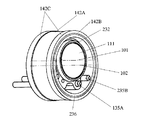
ズームカム筒136及びフォーカスカム筒137の外周側には、ズームモータ140と、フォーカスモータ150とが配置される。ズームモータ140は、ステータ141とロータ142とから構成される。ステータ141は、ステータヨークとして機能する鏡胴体143と、ステータコイル141Aとを有する。ロータ142は、ロータマグネット142Aと、ロータヨーク142Bとを有する。ロータヨーク142Bは、ロータマグネット142Aの端部からの漏れ磁束を低減するためのフランジ部142Cを持つ。
A
フォーカスモータ150は、ステータ151とロータ152とから構成される。ステータ151は、ズームモータ140と共通のステータヨークとして機能する鏡胴体143と、ステータコイル151Aとを有する。ロータ152は、ロータマグネット152Aと、ロータヨーク152Bとを有する。ロータヨーク152Bは、ロータマグネット152Aの端部からの漏れ磁束を低減するためのフランジ部152Cを持つ。
The
図3は、実施の形態1に係る撮像装置のズームモータの分解斜視図である。図1及び図3において、鏡胴体143は、中心軸102まわりに形成される円筒形状である。鏡胴体143は、電磁鋼板などの強磁性体からなり、基盤131と、後述するフロントカバー160により保持される固定筒である。
FIG. 3 is an exploded perspective view of the zoom motor of the imaging apparatus according to the first embodiment. In FIGS. 1 and 3, the
ステータコイル141Aは、鏡胴体143の内周面に固定される。ステータコイル141Aは、渦巻き状に巻かれた複数の小コイルが鏡胴体143の内周面に沿って所定のピッチで配置されている。ロータマグネット142Aは、永久磁石であり、ステータコイル141Aの小コイルと等しい数の磁極を有する。磁極は、ロータヨーク142Bの外周面に沿ってN極及びS極が交互になるように配置されている。ロータヨーク142Bは、電磁鋼板などの強磁性体からなり、ロータマグネット142Aとズームカム筒136との間に配置される。
The
ステータヨークとして機能する鏡胴体143及びステータコイル141Aと、ロータマグネット142A及びロータヨーク142Bとは、磁気回路を構成する。ズームモータ140は、外部からステータコイル141Aの小コイルに所定のタイミングで印加される電流によって磁気回路が駆動され、ロータマグネット142A及びロータヨーク142Bが回転し電磁モータとして機能する。
The
図3では、ズームモータ140の構成を示したが、フォーカスモータ150も、ズームモータ140とほぼ等しい構成を備えている。
Although the configuration of the
すなわち、ステータコイル151Aは、鏡胴体143の内周面に固定される。ステータコイル151Aは、渦巻き状に巻かれた複数の小コイルが鏡胴体143の内周面に沿って所定のピッチで配置されている。ロータヨーク152Bは、フォーカスカム筒137の外周面に接着される。ロータヨーク152Bは、電磁鋼板などの強磁性体からなる。
That is, the
ロータマグネット152Aは、ロータヨーク152Bの外周面に接着される。ロータマグネット152Aは、永久磁石であり、ステータコイル151Aの小コイルの数と等しい磁極を有する。磁極は、ロータヨーク152Bの外周面に沿ってN極及びS極が交互に配置されている。
The
ステータヨークとして機能する鏡胴体143及びステータコイル151Aを含むステータ151と、ロータマグネット152A及びロータヨーク152Bとは、フォーカスモータ150の磁気回路を構成する。フォーカスモータ150は、外部からステータコイル151Aの小コイルに所定のタイミングで印加される電流によって磁気回路が駆動され、ロータマグネット142A及びロータヨーク142Bが回転し電磁モータとして機能する。
The
図1において、フロントカバー160は、光軸101に垂直な円板形状を持つ。フロントカバー160は、撮像装置100の最も被写体側に固定される。フロントカバー160は、ガイドシャフト135A及びガイドシャフト135Bを支持する貫通孔を持つ。
In FIG. 1, the
鏡胴体143の被写体側の端部は、フロントカバー160によって支持される。また、鏡胴体143の像側の端部は、基盤131によって支持される。鏡胴体143がフロントカバー160と基盤131とによって支持されることにより、ステータコイル141Aとロータマグネット142Aとの間の間隔及びステータコイル151Aとロータマグネット152Aとの間の間隔が適切に保持される。
The end of the
以上の構成において、ズーミングを行う場合、外部からズームモータ140のステータコイル141Aの小コイルに所定のタイミングで駆動電流が印加される。駆動電流の印加により磁気回路が駆動され、ロータ142が中心軸102まわりに回転する。
In the above configuration, when zooming is performed, a drive current is applied from the outside to the small coil of the
ロータ142が中心軸102まわりに回転することにより、ズームカム筒136が中心軸102まわりに回転する。ズームカム筒136が中心軸102まわりに回転すると、第1レンズ枠132に設けられたカムピン132Aが、結合しているカム溝に沿って案内される。また、ズームカム筒136が光軸まわりに回転すると、第2レンズ枠133に設けられたカムピンが結合しているカム溝に沿って案内される。
As the
第1レンズ枠132は、ガイドシャフト135Aに案内され、光軸101に平行な方向に移動する。このとき、第1レンズ枠132は、回転規制部132Bがガイドシャフト135Bと係合しているので、光軸101に垂直な面内でのガイドシャフト135Aまわりの回転の自由度が規制されている。したがって、ズームカム筒136が光軸まわりに回転すると回転運動が直進運動へ変換され、第1レンズ枠132はカム溝の位相に従って光軸に平行な方向に移動する。すなわち、ズームカム筒136のカム溝と第1レンズ枠132のカムピン132Aとは、変換機構を構成する。
The
また、同様に第2レンズ枠133は、同様に回転規制部とガイドシャフト135Bとの係合により、光軸101に垂直な面内でのガイドシャフト135Aまわりの回転が規制されている。したがって、ズームカム筒136が光軸まわりに回転すると回転運動が直進運動へ変換され、第2レンズ枠133はカム溝の位相に従って光軸に平行な方向に移動する。
Similarly, the rotation of the
第1レンズ枠132及び第2レンズ枠133が移動することにより、第1ズームレンズ群111及び第2ズームレンズ群112が互いの間隔を変化させながら光軸に平行な方向の所定位置に移動する。この結果、撮像装置100は、ズーミングを行うことができる。
As the
フォーカシングを行う場合、外部からフォーカスモータ150のステータコイル151Aの小コイルに所定のタイミングで駆動電流が印加される。駆動電流の印加により磁気回路に電磁力が発生し、ロータ152が光軸まわりに回転する。
When focusing is performed, a drive current is applied to the small coil of the
ロータ152が光軸まわりに回転することにより、フォーカスカム筒137も光軸まわりに回転する。フォーカスカム筒137が光軸まわりに回転すると、第3レンズ枠134に設けられたカムピンが結合しているカム溝に沿って案内される。
As the
第3レンズ枠134は、同様に回転規制部とガイドシャフト135Bとの係合により、光軸101に垂直な面内でのガイドシャフト135Aまわりの回転の自由度が規制されている。したがって、フォーカスカム筒137が光軸まわりに回転すると回転運動が直進運動へ変換され、第3レンズ枠134はカム溝の位相に従って光軸に平行な方向に移動する。
Similarly, the degree of freedom of rotation of the
図4は、実施の形態1に係る撮像装置の鏡筒において、第1レンズ枠と、2本のガイドシャフトと、3本の軸受け用シャフトとの位置関係を説明する斜視図である。また、図5は、実施の形態1に係る撮像装置の鏡筒において、第1レンズ枠と、2本のガイドシャフトと、3本の軸受け用シャフトとの位置関係を説明する正面図である。なお、図5において、A−A断面は、図1の断面に対応する。 FIG. 4 is a perspective view for explaining the positional relationship among the first lens frame, the two guide shafts, and the three bearing shafts in the lens barrel of the imaging apparatus according to the first embodiment. FIG. 5 is a front view for explaining the positional relationship among the first lens frame, the two guide shafts, and the three bearing shafts in the lens barrel of the imaging apparatus according to the first embodiment. In FIG. 5, the AA cross section corresponds to the cross section of FIG. 1.
図4及び図5において、3本の軸受け用シャフト135C〜135Eは、外接円C1を決定する。外接円C1は、ズームカム筒136の内周面に対応している。一方、仮想円C0は、光軸101と固定筒である鏡胴体143の中心軸102とを一致させた場合において、軸受け用シャフト135Cの接点を基準としたときに必要なズームカム筒の内周面に対応する。
4 and 5, the three bearing
図4及び図5から分かるように、実施の形態1に係る鏡筒は、外接円C1の直径が、仮想円C0の直径より小さくなっている。すなわち、実施の形態1に係る鏡筒は、光軸101と固定筒である鏡胴体143の中心軸102とを一致させないで、両者を互いに平行偏芯させることにより、ズームカム筒136の内周面がコンパクトに構成されている。
As can be seen from FIGS. 4 and 5, in the lens barrel according to the first embodiment, the diameter of the circumscribed circle C1 is smaller than the diameter of the virtual circle C0. In other words, the lens barrel according to
さらに、実施の形態1に係る鏡筒は、ガイドシャフト135A及び回転規制部132Bと係合するガイドシャフト135Bと、中心軸102との間に形成される中心角θ1が180度未満であるので、光軸101と固定筒である鏡胴体143の中心軸102との間の偏芯量が非常に大きくなっている。このように、実施の形態1に係る鏡筒は、光軸101と中心軸102との間の偏芯量が非常に大きいので、ズームカム筒136の内周面は従来と比較して特に光軸に垂直な方向にコンパクトである。
Furthermore, in the lens barrel according to the first embodiment, the central angle θ1 formed between the
ズームカム筒136を小さくすることができると、ズームカム筒136の外周部に配置される固定筒その他の部材を小さくすることができる。したがって、鏡筒全体の小型化が可能である。なお、実施の形態1に係る鏡筒は、ガイドシャフト135A及び回転規制部132Bと係合するガイドシャフト135Bと、中心軸102との間に形成される中心角θ1が90度以下であるので、偏芯量が極めて大きくなっている。
If the
中心軸102は、鏡胴体143及びステータコイル141Aと、ロータマグネット142A及びロータヨーク142Bとからなる磁気回路の対称中心でもある。実施の形態1に係る撮像装置は、光軸101と駆動用の電磁モータを構成する磁気回路の中心軸102とを一致させないで両者を互いに平行偏芯させることにより、駆動用の電磁モータを有する構成において、ズームカム筒136の内周面をコンパクトに構成することが可能になっている。
The
(実施の形態2)
図6は、実施の形態2に係る鏡筒の一部分の斜視図である。また、図7は、実施の形態2に係る鏡筒の一部分の正面図である。実施の形態2に係る鏡筒は、実施の形態1に係る鏡筒130と概略構成が同一であるので、以下相違する部分を中心に、特徴構成を説明する。図6は、実施の形態2に係る鏡筒において、第1ズームレンズ群111を保持する第1レンズ枠232の周辺の構造を示す斜視図であり、図7は、図6に示す構造の正面図に対応する。
(Embodiment 2)
FIG. 6 is a perspective view of a part of a lens barrel according to the second embodiment. FIG. 7 is a front view of a part of the lens barrel according to the second embodiment. Since the lens barrel according to the second embodiment has the same schematic configuration as that of the lens barrel 130 according to the first embodiment, the characteristic configuration will be described below focusing on the differences. 6 is a perspective view showing the structure around the
第1レンズ枠232は、第1ズームレンズ群111を保持する。第1レンズ枠232は、光軸101を中心軸とする略円筒形状である。第1レンズ枠232は、外周部に、外周方向に突出したカムピン232Aと、回転規制部232Bと、光軸101に平行な貫通孔232Cとを有する。カムピン232Aは、ズームカム筒236に設けられた図示しないカム溝と係合する。回転規制部232Bは、光軸101に直交する方向にわずかの遊びを形成しつつガイドシャフト235Bと係合する。貫通孔232Cは、ガイドシャフト135Aと嵌合する。
The
ズームカム筒236は、円筒形状を有する。ズームカム筒236は、中心軸102回りに回転可能である。ズームカム筒236は、外周部にロータヨーク142Bを固定し、さらにその外周部にロータマグネット142Aを固定する。ロータマグネット142A及びロータヨーク142Bは、実施の形態1において説明した鏡胴体143及びステータコイル141Aとともにズームモータ140の磁気回路を構成する。また、ロータマグネット142Aの光軸101に平行な方向の両端部は、外部の中空軸受けと摺動する軸受け部142Cが形成される。ズームカム筒236は、実施の形態1に係る鏡筒130のように、3本の軸受け用シャフト135C〜135Eにより回転可能に保持される構造とは異なり、ズームカム筒236はロータヨーク142B等を介して、図示しない外部の中空軸受けにより、中心軸102回りに回転可能に保持される。
The
実施の形態2に係る鏡筒を適用した撮像装置において、ズームモータ140が駆動されてズームカム筒236が回転すると、第1レンズ枠232が光軸101に平行な方向に移動して、第1ズームレンズ群111を光軸101に沿って移動させることができる。
In the imaging apparatus to which the lens barrel according to the second embodiment is applied, when the
図8は、実施の形態2に係る鏡筒において、第1レンズ枠と、2本のガイドシャフトの位置関係を説明する正面図である。図8において、円C1は、ズームカム筒236の内周面に相当する。また、仮想円C0は、光軸101と固定筒である鏡胴体143の中心軸102とを一致させた場合において、ガイドシャフト235Bの接点を基準としたときのズームカム筒に必要な内周面に対応する。
FIG. 8 is a front view illustrating the positional relationship between the first lens frame and the two guide shafts in the lens barrel according to the second embodiment. In FIG. 8, a circle C <b> 1 corresponds to the inner peripheral surface of the
図8から分かるように、実施の形態8に係る鏡筒は、円C1の直径が、仮想円C0の直径より小さくなっている。すなわち、実施の形態2に係る鏡筒は、光軸101と固定筒である鏡胴体143の中心軸102とを一致させないで、両者を互いに平行偏芯させることにより、ズームカム筒236の内周面がコンパクトに構成されている。
As can be seen from FIG. 8, in the lens barrel according to the eighth embodiment, the diameter of the circle C1 is smaller than the diameter of the virtual circle C0. In other words, the lens barrel according to the second embodiment is configured so that the
さらに、実施の形態2に係る鏡筒は、ガイドシャフト135A及び回転規制部232Bと係合するガイドシャフト235Bと、中心軸102との間に形成される中心角θ1が180度未満であるので、光軸101と固定筒である鏡胴体143の中心軸102との間の偏芯量が非常に大きくなっている。このように、実施の形態1に係る鏡筒は、光軸101と中心軸102との間の偏芯量が非常に大きいので、ズームカム筒236の内周面は従来と比較して特にコンパクトである。
Furthermore, in the lens barrel according to the second embodiment, the central angle θ1 formed between the
実施の形態2に係る鏡筒のように、ズームカム筒236を小さくすることができると、ズームカム筒236の外周部に配置される固定筒その他の部材を小さくすることができる。したがって、鏡筒全体の小型化が可能である。なお、実施の形態2に係る鏡筒は、ガイドシャフト135A及び回転規制部232Bと係合するガイドシャフト235Bと、中心軸102との間に形成される中心角が90度以下であるので、偏芯量が極めて大きくなっている。
If the
図11は、実施の形態2に係る鏡筒において、ズームカム筒の内周面に相当する円C1の直径と、中心角θ1との関係を示すグラフである。図11において、グラフの縦軸は、外接円である円C1の直径を表し、横軸は中心角θ1を表す。図11から分かるように、中心角θ1が小さくなればなるほど、円C1の直径が小さくなっている。したがって、中心角θ1は、180度未満であれば、円C1を小さくすることができる。しかしながら、鏡筒の小型化と回転規制の効果とのバランスを考慮した場合、中心角θ1は、150度未満、特に90度未満であることが望ましい。 FIG. 11 is a graph showing the relationship between the diameter of the circle C1 corresponding to the inner peripheral surface of the zoom cam cylinder and the central angle θ1 in the lens barrel according to the second embodiment. In FIG. 11, the vertical axis of the graph represents the diameter of a circle C1 that is a circumscribed circle, and the horizontal axis represents the central angle θ1. As can be seen from FIG. 11, the smaller the central angle θ1, the smaller the diameter of the circle C1. Therefore, if the central angle θ1 is less than 180 degrees, the circle C1 can be reduced. However, considering the balance between the size reduction of the lens barrel and the effect of the rotation restriction, it is desirable that the center angle θ1 is less than 150 degrees, particularly less than 90 degrees.
中心軸102は、鏡胴体143及びステータコイル141Aと、ロータマグネット142A及びロータヨーク142Bとからなる磁気回路の対称中心でもある。実施の形態2に係る撮像装置は、光軸101と駆動用の電磁モータを構成する磁気回路の中心軸102とを一致させないで両者を互いに平行偏芯させることにより、駆動用の電磁モータを有する構成において、ズームカム筒236の内周面をコンパクトに構成する。
The
(実施の形態3)
図9は、実施の形態3に係る鏡筒の構成を示す模式図であり、図9(a)は、正面図、図9(b)は、平面図に対応する。実施の形態3に係る鏡筒は、実施の形態1及び実施の形態2に係る鏡筒とは異なり、ボイスコイル型モータを用いてレンズ群を駆動する。
(Embodiment 3)
FIG. 9 is a schematic diagram illustrating a configuration of a lens barrel according to the third embodiment. FIG. 9A corresponds to a front view, and FIG. 9B corresponds to a plan view. Unlike the lens barrels according to the first and second embodiments, the lens barrel according to the third embodiment drives a lens group using a voice coil motor.
図9(a)及び(b)において、第1レンズ枠301は、円筒形状を有する。第1レンズ枠301は、内部に第1レンズ群111を保持する。第1レンズ111の光軸と、第1レンズ枠301の中心軸は一致しておらず、両者は平行偏芯されて配置されている。
9A and 9B, the
第1レンズ枠301は、光軸101に平行に設けられた2つの貫通孔を有する。一方の貫通孔301Aは、ガイドシャフト135Aと嵌合し、第1レンズ枠132を光軸に平行な方向に案内する。他方の貫通孔301B(回転規制部)は、ガイドシャフト135Bと、第1レンズ枠301の光軸回りの方向にわずかの遊びを持って係合している。第1レンズ枠301は、外周部にコイル303が巻回されている。また、第1レンズ枠301の周囲には、光軸101に平行な方向に磁極を向けたマグネットが配置されている。したがって、中心軸102は、コイル303とマグネット302とから構成される磁気回路の対称中心である。
The
以上の構成において、外部からコイル303に電流が供給されると、磁気回路に電磁力が発生し、第1レンズ枠301は、電流の向きに応じて光軸101と平行な方向に駆動される。
In the above configuration, when a current is supplied to the
実施の形態3に係る鏡筒は、光軸101と駆動用の電磁モータを構成する磁気回路の中心軸102とを一致させないで両者を互いに平行偏芯させることにより、第1レンズ枠301全体をコンパクトに構成させている。特に、実施の形態3に係る鏡筒は、ガイドシャフト135A及び貫通孔301Bと係合するガイドシャフト235Bと、中心軸102との間に形成される中心角θ1が180度未満であるので、光軸101と中心軸102との間の偏芯量が非常に大きくなっている。
In the lens barrel according to the third embodiment, the
このように、実施の形態3に係る鏡筒は、光軸101と中心軸102との間の偏芯量が非常に大きいので、第1レンズ枠301自体が従来と比較して特にコンパクトである。また、実施の形態3に係る鏡筒は、カム筒や固定筒などが不要であるため、極めてコンパクトに構成されている。実施の形態3に係る鏡筒は、ガイドシャフト135A及び貫通孔301Bと係合するガイドシャフト135Bと、中心軸102との間に形成される中心角が90度以下であるので、偏芯量が極めて大きくなっている。
As described above, in the lens barrel according to the third embodiment, the amount of eccentricity between the
(実施の形態4)
図12は、実施の形態4に係る鏡筒において、第1レンズ枠と、ガイドシャフトと回転規制部との位置関係を説明する正面図である。実施の形態4に係る鏡筒は、実施の形態1に係る鏡筒130と概略構成が同一であるので、以下相違する部分を中心に、特徴構成を説明する。
(Embodiment 4)
FIG. 12 is a front view illustrating the positional relationship among the first lens frame, the guide shaft, and the rotation restricting portion in the lens barrel according to the fourth embodiment. Since the lens barrel according to the fourth embodiment has the same schematic configuration as that of the lens barrel 130 according to the first embodiment, the characteristic configuration will be described below focusing on the differences.
図12において、円C1は、図示しないズームカム筒の内周面に相当する。また、仮想円C0は、光軸101と固定筒である鏡胴体の中心軸102とを一致させた場合において、ズームカム筒に必要な内周面に対応する。なお、回転規制部335Bは、固定筒側に設けられた貫通孔に嵌合し、光軸方向に延びた棒状の構成を持つ。
In FIG. 12, a circle C1 corresponds to the inner peripheral surface of a zoom cam cylinder (not shown). The virtual circle C0 corresponds to the inner peripheral surface necessary for the zoom cam cylinder when the
図13は、実施の形態4の変形例に係る鏡筒において、第1レンズ枠と、ガイドシャフトと回転規制部との位置関係を説明する正面図である。変形例に係る鏡筒は、回転規制部335Bの代わりに、中心軸102を挟んで対称に配置された、2つの回転規制部435Bと435Cとを含む。各回転規制部の構成は、図12に示した回転規制部335Bと共通である。
FIG. 13 is a front view illustrating the positional relationship among the first lens frame, the guide shaft, and the rotation restricting portion in the lens barrel according to the modification of the fourth embodiment. The lens barrel according to the modified example includes two
図12及び図13から分かるように、実施の形態4に係る鏡筒は、円C1の直径が、仮想円C0の直径より小さくなっている。すなわち、実施の形態4に係る鏡筒は、光軸101と固定筒である鏡胴体の中心軸102とを一致させないで、両者を互いに平行偏芯させることにより、ズームカム筒の内周面がコンパクトに構成されている。
As can be seen from FIGS. 12 and 13, in the lens barrel according to the fourth embodiment, the diameter of the circle C1 is smaller than the diameter of the virtual circle C0. In other words, the lens barrel according to the fourth embodiment has a compact inner peripheral surface of the zoom cam barrel by aligning the
さらに、実施の形態4に係る鏡筒は、ガイドシャフト135A及び回転規制部435Bと、中心軸102との間に形成される中心角θ1が180度未満であるので、光軸101と固定筒である鏡胴体の中心軸102との間の偏芯量が非常に大きくなっている。このように、実施の形態4に係る鏡筒は、光軸101と中心軸102との間の偏芯量が非常に大きいので、ズームカム筒の内周面は従来と比較して特にコンパクトである。
Furthermore, the lens barrel according to the fourth embodiment has a center angle θ1 formed between the
特に、実施の形態4の変形例に係る鏡筒は、ガイドシャフト135A及び回転規制部435Cと、中心軸102との間に形成される中心角θ2も180度未満であるので、光軸101と固定筒である鏡胴体の中心軸102との間の偏芯量を大きくしつつ、回転規制を安定して行うことができる。
In particular, in the lens barrel according to the modification of the fourth embodiment, the central angle θ2 formed between the
なお、以上説明した各実施の形態は、適宜変形することができる。例えば、撮像光学系の構成は、3つのレンズ群からなるズームレンズ系に限られない。2つあるいは4つ以上のレンズ群からなるズームレンズ系であってもよい。ズームレンズ系の構成に応じて、実施の形態1乃至実施の形態4の鏡筒の機構を適用すればよい。
Each embodiment described above can be modified as appropriate. For example, the configuration of the imaging optical system is not limited to a zoom lens system including three lens groups. It may be a zoom lens system composed of two or four or more lens groups. The lens barrel mechanism of
また、撮像光学系が、単焦点レンズ系であってもよい。この場合、すべての撮像光学系を繰り出してフォーカスを行う、あるいは一部のレンズ群を繰り出してフォーカスを行う等が知られているが、これらの鏡筒に実施の形態1乃至実施の形態4の鏡筒の機構を適用すればよい。 Further, the imaging optical system may be a single focus lens system. In this case, it is known that all the imaging optical systems are extended to perform focusing, or some lens groups are extended to perform focusing. However, these lens barrels are not limited to those described in the first to fourth embodiments. A lens barrel mechanism may be applied.
また、各実施の形態の鏡筒は、レンズ枠の回転規制部を、光軸と平行な方向に沿って配置されたシャフトと係合させる構成であったが、これに限られない。例えば、回転規制部を、レンズ枠の外部であってカム筒の内部に光軸に平行な方向に沿って設けられた案内溝などの構成要素に係合させてもよい。 In addition, the lens barrel of each embodiment is configured to engage the rotation restricting portion of the lens frame with a shaft arranged along a direction parallel to the optical axis, but is not limited thereto. For example, the rotation restricting portion may be engaged with a component such as a guide groove provided outside the lens frame and inside the cam cylinder along a direction parallel to the optical axis.
また、実施の形態1、実施の形態2及び実施の形態4に係る撮像装置において、磁気回路は、ステータがステータコイルを含み、ロータがロータマグネットを含む構成であったが、これに限られない。電磁モータとして、ステータがステータマグネットを含み、ロータがロータコイルを含む構成であってもよい。
Further, in the imaging devices according to
図10は、各実施の形態の撮像装置を適用した携帯電話端末の一例を示す斜視図である。携帯電話端末400は、折りたたみ型であり、ヒンジ部401を備えている。この例では、実施の形態1に係る撮像装置100が、携帯電話端末400のヒンジ部401に設けられている。前述のように、撮像装置100は、固定筒の中心軸とレンズ群の光軸とを平行偏芯させて配置させることにより、光軸に垂直な方向にコンパクトに構成されているので、ヒンジ部401をコンパクトにすることが可能である。したがって、撮像装置100は、携帯電話端末400を薄く構成することができる。
FIG. 10 is a perspective view showing an example of a mobile phone terminal to which the imaging device of each embodiment is applied. The
もちろん、撮像装置100を、携帯電話端末400のヒンジ部401以外に配置してもよいことはいうまでもない。撮像装置100は、特に光軸に垂直な方向にコンパクトに構成されているので、いずれの位置に配置されても、携帯電話端末の小型化に寄与することができる。
Of course, it goes without saying that the
撮像装置100は、デジタルスチルカメラ、デジタルビデオカメラ、PDA(Personal Digital Assistance)等の機器に搭載してもよい。いずれの機器に搭載しても、それらの機器のコンパクト化に寄与することができる。また、撮像装置100の代わりに実施の形態2乃至実施の形態4の撮像装置を、上述の機器に配置してもよい。
The
本発明の鏡筒ならびに撮像装置は、小型化と高機能化が要望されている、デジタルスチルカメラ、デジタルビデオカメラ、カメラ機能付きの携帯電話端末及びPDA等に好適である。 The lens barrel and the imaging apparatus of the present invention are suitable for digital still cameras, digital video cameras, mobile phone terminals with camera functions, PDAs, and the like, which are required to be downsized and highly functional.
100 撮像装置
101 光軸
102 中心軸
110 撮像光学系
111 第1ズームレンズ群
112 第2ズームレンズ群
113 フォーカスレンズ群
114 ローパスフィルタ
120 撮像センサ
130 鏡筒
131 基盤
132 第1レンズ枠
132A カムピン
132B 回転規制部
132C 貫通孔
133 第2レンズ枠
134 第3レンズ枠
135A ガイドシャフト
135B ガイドシャフト
135C 軸受け用シャフト
135D 軸受け用シャフト
135E 軸受け用シャフト
136 ズームカム筒
137 フォーカスカム筒
140 ズームモータ
141 ステータ
142 ロータ
143 鏡胴体
150 フォーカスモータ
151 ステータ
152 ロータ
160 フロントカバー
232 第1レンズ枠
232A カムピン
232B 回転規制部
232C 貫通孔
235B ガイドシャフト
236 ズームカム筒
301 第1レンズ枠
302 マグネット
303 コイル
335B 回転規制部
400 携帯電話端末
401 ヒンジ部
435B 回転規制部
435C 回転規制部
DESCRIPTION OF
Claims (3)
所定のレンズ群から構成され、前記被写体の光学的な像を形成する撮像光学系と、
前記撮像光学系によって形成された光学的な像を受光し、前記光学的な像を前記電気的な画像信号に変換する撮像センサと、
前記撮像光学系の一部又は全部のレンズ群を保持する鏡筒とを備え、
前記鏡筒は、
前記レンズ群を保持するレンズ枠と、
前記レンズ枠を前記撮像光学系の光軸に沿って移動させるための電磁モータと、
前記レンズ枠と係合し、前記レンズ枠を前記レンズ群の前記光軸に平行な方向に案内する少なくとも1本のシャフトと、
前記レンズ枠の外周部に設けられ、前記レンズ枠が前記シャフト回りに回転することを規制する回転規制部とを含み、
前記電磁モータは、前記光軸に平行な対称軸まわりに回転対称な磁気回路を含み、
前記レンズ枠は、前記磁気回路の対称軸と前記レンズ群の前記光軸とが一致しないように、前記磁気回路に対して平行偏芯させて配置され、
前記シャフトと前記回転規制部とは、前記磁気回路の内側であって、前記磁気回路の前記対称軸に対する中心角が180度未満になる位置に配置され、
前記磁気回路の前記対称軸は、前記レンズ群の前記光軸よりも前記シャフトおよび前記回転規制部に近い位置に配置されることを特徴とする、撮像装置。 An imaging device that outputs an image of a subject as an electrical image signal,
An imaging optical system that includes a predetermined lens group and forms an optical image of the subject;
An imaging sensor that receives an optical image formed by the imaging optical system and converts the optical image into the electrical image signal;
A lens barrel that holds a part or all of the lens group of the imaging optical system,
The lens barrel is
A lens frame for holding the lens group;
An electromagnetic motor for moving the lens frame along the optical axis of the imaging optical system;
At least one shaft engaged with the lens frame and guiding the lens frame in a direction parallel to the optical axis of the lens group;
A rotation restricting portion that is provided on an outer peripheral portion of the lens frame and restricts the lens frame from rotating around the shaft;
The electromagnetic motor includes a magnetic circuit that is rotationally symmetric about an axis of symmetry parallel to the optical axis,
The lens frame is arranged to be decentered parallel to the magnetic circuit so that the symmetry axis of the magnetic circuit does not coincide with the optical axis of the lens group,
The shaft and the rotation restricting portion are arranged inside the magnetic circuit at a position where a central angle with respect to the symmetry axis of the magnetic circuit is less than 180 degrees,
The imaging apparatus according to claim 1, wherein the symmetry axis of the magnetic circuit is disposed at a position closer to the shaft and the rotation restricting unit than the optical axis of the lens group.
前記電磁モータは、内部に前記レンズ枠を配置した円筒状のロータを含み、
前記磁気回路は、
前記固定筒に設けられたステータ及び、前記ロータの内、いずれか一方に設けられたコイルと、他方に設けられたマグネットとを含む、請求項1に記載の撮像装置。 The lens barrel includes a cylindrical fixed cylinder,
The electromagnetic motor includes a cylindrical rotor having the lens frame disposed therein,
The magnetic circuit is:
The imaging device according to claim 1, comprising: a stator provided on the fixed cylinder; a coil provided on one of the rotors; and a magnet provided on the other.
前記レンズ枠の周囲に巻回されたコイルと、前記レンズ枠の外部に配置されたマグネットとを含む、請求項1に記載の撮像装置。 The magnetic circuit is:
The imaging device according to claim 1, comprising: a coil wound around the lens frame; and a magnet disposed outside the lens frame.
Priority Applications (1)
| Application Number | Priority Date | Filing Date | Title |
|---|---|---|---|
| JP2005137555A JP4751639B2 (en) | 2004-05-28 | 2005-05-10 | Lens tube, imaging device including lens barrel |
Applications Claiming Priority (3)
| Application Number | Priority Date | Filing Date | Title |
|---|---|---|---|
| JP2004159187 | 2004-05-28 | ||
| JP2004159187 | 2004-05-28 | ||
| JP2005137555A JP4751639B2 (en) | 2004-05-28 | 2005-05-10 | Lens tube, imaging device including lens barrel |
Publications (2)
| Publication Number | Publication Date |
|---|---|
| JP2006011384A JP2006011384A (en) | 2006-01-12 |
| JP4751639B2 true JP4751639B2 (en) | 2011-08-17 |
Family
ID=35778672
Family Applications (1)
| Application Number | Title | Priority Date | Filing Date |
|---|---|---|---|
| JP2005137555A Expired - Fee Related JP4751639B2 (en) | 2004-05-28 | 2005-05-10 | Lens tube, imaging device including lens barrel |
Country Status (1)
| Country | Link |
|---|---|
| JP (1) | JP4751639B2 (en) |
Families Citing this family (3)
| Publication number | Priority date | Publication date | Assignee | Title |
|---|---|---|---|---|
| JP2005351966A (en) * | 2004-06-08 | 2005-12-22 | Fujinon Corp | Lens driving device and imaging apparatus |
| KR101476651B1 (en) * | 2008-07-07 | 2014-12-26 | 삼성전자주식회사 | Lens assembly |
| KR101780856B1 (en) | 2012-06-07 | 2017-10-10 | 아사히 가세이 일렉트로닉스 가부시끼가이샤 | Position detection device |
Family Cites Families (9)
| Publication number | Priority date | Publication date | Assignee | Title |
|---|---|---|---|---|
| JPH0812322B2 (en) * | 1986-03-24 | 1996-02-07 | 株式会社ニコン | camera |
| JPH0694960A (en) * | 1992-09-17 | 1994-04-08 | Minolta Camera Co Ltd | Bearing structure |
| JP3387173B2 (en) * | 1993-10-27 | 2003-03-17 | ソニー株式会社 | Electromagnetic drive |
| JPH08201673A (en) * | 1995-01-30 | 1996-08-09 | Minolta Co Ltd | Eccentricity adjusting device for lens and parallax adjusting device using the same |
| JPH1090584A (en) * | 1996-01-26 | 1998-04-10 | Konica Corp | Lens device |
| JP3746574B2 (en) * | 1996-08-12 | 2006-02-15 | オリンパス株式会社 | Photography lens device |
| JP4724294B2 (en) * | 2000-12-05 | 2011-07-13 | キヤノン株式会社 | Lens barrel and method of assembling lens barrel |
| JP2003140218A (en) * | 2001-11-07 | 2003-05-14 | Tamron Co Ltd | Image blur correction lens system |
| JP3977187B2 (en) * | 2002-07-29 | 2007-09-19 | キヤノン株式会社 | Stepping motor and optical device |
-
2005
- 2005-05-10 JP JP2005137555A patent/JP4751639B2/en not_active Expired - Fee Related
Also Published As
| Publication number | Publication date |
|---|---|
| JP2006011384A (en) | 2006-01-12 |
Similar Documents
| Publication | Publication Date | Title |
|---|---|---|
| JP4910998B2 (en) | Image blur correction device, lens barrel, and imaging device | |
| JP4739681B2 (en) | Tube | |
| US8248709B2 (en) | Zoom lens barrel that attains a higher photographing magnification | |
| US7292396B2 (en) | Lens device, image pickup device and optical device | |
| US8315001B2 (en) | Lens barrel | |
| US7359631B2 (en) | Lens driving device, imaging device using the same, and small-sized electronics device using the same | |
| JP2011081426A (en) | Lens barrel and imaging apparatus with lens barrel | |
| JP4784453B2 (en) | Rotating device, light beam deflecting device, shake correcting device, and optical device | |
| JP2007110885A (en) | Stepping motor and electronic equipment | |
| US7466503B2 (en) | Zoom lens lens-barrel and imaging apparatus | |
| JPH0894905A (en) | Lens barrel | |
| US7414801B2 (en) | Lens barrel and image pickup device including lens barrel | |
| JP5337093B2 (en) | Lens barrel | |
| JP4751639B2 (en) | Lens tube, imaging device including lens barrel | |
| JP4694851B2 (en) | Retractable lens barrel | |
| JP2010186192A5 (en) | ||
| US10539857B2 (en) | Shutter apparatus and imaging apparatus | |
| JP2005202316A (en) | Hollow motor integrated type lens barrel | |
| US7274120B2 (en) | Drive unit and image pickup unit equipped with the drive unit | |
| US7116902B2 (en) | Lens driving mechanism and electronic device | |
| JP5867994B2 (en) | Lens barrel and optical equipment | |
| JP2013064812A (en) | Optical vibration-proof device and optical instrument | |
| JP2024112386A (en) | Imaging apparatus | |
| JP2024103947A (en) | Lens device equipped with image blur correction device | |
| JPS60415A (en) | Lens driving device |
Legal Events
| Date | Code | Title | Description |
|---|---|---|---|
| A621 | Written request for application examination |
Free format text: JAPANESE INTERMEDIATE CODE: A621 Effective date: 20080430 |
|
| A977 | Report on retrieval |
Free format text: JAPANESE INTERMEDIATE CODE: A971007 Effective date: 20100825 |
|
| A131 | Notification of reasons for refusal |
Free format text: JAPANESE INTERMEDIATE CODE: A131 Effective date: 20100906 |
|
| A521 | Request for written amendment filed |
Free format text: JAPANESE INTERMEDIATE CODE: A523 Effective date: 20101105 |
|
| A131 | Notification of reasons for refusal |
Free format text: JAPANESE INTERMEDIATE CODE: A131 Effective date: 20110106 |
|
| A521 | Request for written amendment filed |
Free format text: JAPANESE INTERMEDIATE CODE: A523 Effective date: 20110307 |
|
| TRDD | Decision of grant or rejection written | ||
| A01 | Written decision to grant a patent or to grant a registration (utility model) |
Free format text: JAPANESE INTERMEDIATE CODE: A01 Effective date: 20110511 |
|
| A01 | Written decision to grant a patent or to grant a registration (utility model) |
Free format text: JAPANESE INTERMEDIATE CODE: A01 |
|
| A61 | First payment of annual fees (during grant procedure) |
Free format text: JAPANESE INTERMEDIATE CODE: A61 Effective date: 20110523 |
|
| R150 | Certificate of patent or registration of utility model |
Free format text: JAPANESE INTERMEDIATE CODE: R150 |
|
| FPAY | Renewal fee payment (event date is renewal date of database) |
Free format text: PAYMENT UNTIL: 20140527 Year of fee payment: 3 |
|
| LAPS | Cancellation because of no payment of annual fees |